EP3737802B1 - Set of panels - Google Patents
Set of panels Download PDFInfo
- Publication number
- EP3737802B1 EP3737802B1 EP18899265.5A EP18899265A EP3737802B1 EP 3737802 B1 EP3737802 B1 EP 3737802B1 EP 18899265 A EP18899265 A EP 18899265A EP 3737802 B1 EP3737802 B1 EP 3737802B1
- Authority
- EP
- European Patent Office
- Prior art keywords
- edge
- locking
- panel
- panels
- cooperate
- Prior art date
- Legal status (The legal status is an assumption and is not a legal conclusion. Google has not performed a legal analysis and makes no representation as to the accuracy of the status listed.)
- Active
Links
- 238000006073 displacement reaction Methods 0.000 claims description 12
- -1 polypropylene Polymers 0.000 description 24
- 210000002105 tongue Anatomy 0.000 description 21
- 239000012815 thermoplastic material Substances 0.000 description 15
- 239000004698 Polyethylene Substances 0.000 description 12
- 239000004743 Polypropylene Substances 0.000 description 12
- 229920000573 polyethylene Polymers 0.000 description 12
- 229920000139 polyethylene terephthalate Polymers 0.000 description 12
- 239000005020 polyethylene terephthalate Substances 0.000 description 12
- 229920001155 polypropylene Polymers 0.000 description 12
- CERQOIWHTDAKMF-UHFFFAOYSA-M Methacrylate Chemical compound CC(=C)C([O-])=O CERQOIWHTDAKMF-UHFFFAOYSA-M 0.000 description 6
- 239000004793 Polystyrene Substances 0.000 description 6
- 239000011888 foil Substances 0.000 description 6
- 229920002037 poly(vinyl butyral) polymer Polymers 0.000 description 6
- 229920000058 polyacrylate Polymers 0.000 description 6
- 229920001707 polybutylene terephthalate Polymers 0.000 description 6
- 229920000515 polycarbonate Polymers 0.000 description 6
- 239000004417 polycarbonate Substances 0.000 description 6
- 229920000728 polyester Polymers 0.000 description 6
- 239000004814 polyurethane Substances 0.000 description 6
- 239000004800 polyvinyl chloride Substances 0.000 description 6
- 239000000463 material Substances 0.000 description 4
- 239000002699 waste material Substances 0.000 description 3
- 238000010017 direct printing Methods 0.000 description 2
- 239000011120 plywood Substances 0.000 description 2
- 238000007639 printing Methods 0.000 description 2
- 239000012858 resilient material Substances 0.000 description 2
- 238000000926 separation method Methods 0.000 description 2
- 239000002023 wood Substances 0.000 description 2
- 239000013013 elastic material Substances 0.000 description 1
- 238000000034 method Methods 0.000 description 1
- 238000003801 milling Methods 0.000 description 1
- 238000003825 pressing Methods 0.000 description 1
Images


Classifications
-
- E—FIXED CONSTRUCTIONS
- E04—BUILDING
- E04F—FINISHING WORK ON BUILDINGS, e.g. STAIRS, FLOORS
- E04F15/00—Flooring
- E04F15/02—Flooring or floor layers composed of a number of similar elements
- E04F15/02038—Flooring or floor layers composed of a number of similar elements characterised by tongue and groove connections between neighbouring flooring elements
-
- E—FIXED CONSTRUCTIONS
- E04—BUILDING
- E04F—FINISHING WORK ON BUILDINGS, e.g. STAIRS, FLOORS
- E04F13/00—Coverings or linings, e.g. for walls or ceilings
- E04F13/07—Coverings or linings, e.g. for walls or ceilings composed of covering or lining elements; Sub-structures therefor; Fastening means therefor
- E04F13/08—Coverings or linings, e.g. for walls or ceilings composed of covering or lining elements; Sub-structures therefor; Fastening means therefor composed of a plurality of similar covering or lining elements
-
- E—FIXED CONSTRUCTIONS
- E04—BUILDING
- E04F—FINISHING WORK ON BUILDINGS, e.g. STAIRS, FLOORS
- E04F15/00—Flooring
- E04F15/02—Flooring or floor layers composed of a number of similar elements
- E04F15/02005—Construction of joints, e.g. dividing strips
- E04F15/02033—Joints with beveled or recessed upper edges
-
- E—FIXED CONSTRUCTIONS
- E04—BUILDING
- E04F—FINISHING WORK ON BUILDINGS, e.g. STAIRS, FLOORS
- E04F15/00—Flooring
- E04F15/02—Flooring or floor layers composed of a number of similar elements
- E04F15/10—Flooring or floor layers composed of a number of similar elements of other materials, e.g. fibrous or chipped materials, organic plastics, magnesite tiles, hardboard, or with a top layer of other materials
- E04F15/102—Flooring or floor layers composed of a number of similar elements of other materials, e.g. fibrous or chipped materials, organic plastics, magnesite tiles, hardboard, or with a top layer of other materials of fibrous or chipped materials, e.g. bonded with synthetic resins
-
- E—FIXED CONSTRUCTIONS
- E04—BUILDING
- E04F—FINISHING WORK ON BUILDINGS, e.g. STAIRS, FLOORS
- E04F15/00—Flooring
- E04F15/02—Flooring or floor layers composed of a number of similar elements
- E04F15/10—Flooring or floor layers composed of a number of similar elements of other materials, e.g. fibrous or chipped materials, organic plastics, magnesite tiles, hardboard, or with a top layer of other materials
- E04F15/105—Flooring or floor layers composed of a number of similar elements of other materials, e.g. fibrous or chipped materials, organic plastics, magnesite tiles, hardboard, or with a top layer of other materials of organic plastics with or without reinforcements or filling materials
-
- E—FIXED CONSTRUCTIONS
- E04—BUILDING
- E04F—FINISHING WORK ON BUILDINGS, e.g. STAIRS, FLOORS
- E04F15/00—Flooring
- E04F15/02—Flooring or floor layers composed of a number of similar elements
- E04F15/10—Flooring or floor layers composed of a number of similar elements of other materials, e.g. fibrous or chipped materials, organic plastics, magnesite tiles, hardboard, or with a top layer of other materials
- E04F15/107—Flooring or floor layers composed of a number of similar elements of other materials, e.g. fibrous or chipped materials, organic plastics, magnesite tiles, hardboard, or with a top layer of other materials composed of several layers, e.g. sandwich panels
-
- E—FIXED CONSTRUCTIONS
- E04—BUILDING
- E04F—FINISHING WORK ON BUILDINGS, e.g. STAIRS, FLOORS
- E04F2201/00—Joining sheets or plates or panels
- E04F2201/01—Joining sheets, plates or panels with edges in abutting relationship
- E04F2201/0107—Joining sheets, plates or panels with edges in abutting relationship by moving the sheets, plates or panels substantially in their own plane, perpendicular to the abutting edges
-
- E—FIXED CONSTRUCTIONS
- E04—BUILDING
- E04F—FINISHING WORK ON BUILDINGS, e.g. STAIRS, FLOORS
- E04F2201/00—Joining sheets or plates or panels
- E04F2201/01—Joining sheets, plates or panels with edges in abutting relationship
- E04F2201/0138—Joining sheets, plates or panels with edges in abutting relationship by moving the sheets, plates or panels perpendicular to the main plane
- E04F2201/0146—Joining sheets, plates or panels with edges in abutting relationship by moving the sheets, plates or panels perpendicular to the main plane with snap action of the edge connectors
-
- E—FIXED CONSTRUCTIONS
- E04—BUILDING
- E04F—FINISHING WORK ON BUILDINGS, e.g. STAIRS, FLOORS
- E04F2201/00—Joining sheets or plates or panels
- E04F2201/01—Joining sheets, plates or panels with edges in abutting relationship
- E04F2201/0153—Joining sheets, plates or panels with edges in abutting relationship by rotating the sheets, plates or panels around an axis which is parallel to the abutting edges, possibly combined with a sliding movement
- E04F2201/0161—Joining sheets, plates or panels with edges in abutting relationship by rotating the sheets, plates or panels around an axis which is parallel to the abutting edges, possibly combined with a sliding movement with snap action of the edge connectors
-
- E—FIXED CONSTRUCTIONS
- E04—BUILDING
- E04F—FINISHING WORK ON BUILDINGS, e.g. STAIRS, FLOORS
- E04F2201/00—Joining sheets or plates or panels
- E04F2201/02—Non-undercut connections, e.g. tongue and groove connections
- E04F2201/023—Non-undercut connections, e.g. tongue and groove connections with a continuous tongue or groove
Definitions
- the present disclosure relates to panels, such as floorboards, which are configured to be locked together.
- Panels are known that are configured to be assembled by a vertical displacement and to be locked together in a vertical direction and in a horizontal direction. Such panels are disclosed in e.g., WO 2014/182215 .
- a tongue and groove connection locks a first edge of a first panel to a second edge of the second panel.
- the first edge and the second edge include a locking element configured to cooperate with a locking groove for locking in the vertical and the horizontal direction.
- WO 2005/098163 relates to a panel element comprising two different locking elements.
- This type of panels has the disadvantage that the junction between two panels needs to be long and that a lot of panel material thereby goes to waste when producing this type of panels.
- US 2004/177584 discloses floorboards for mechanical joining of floors in a herringbone pattern and in parallel rows with horizontal connectors which on the short sides have cooperating locking surfaces which are designed differently from the cooperating locking surfaces on the long sides.
- US 2008/295432 discloses a set of floor panels adapted to be locked to other panels mechanically, having an edge portion with a sidewardly open groove, in which groove a tongue formed as a separate part is received.
- WO 2017/187298 discloses a set of floor panels, which is suitable for forming a floor covering in herringbone pattern, wherein these floor panels are oblong rectangular and comprise a pair of long edges and a pair of short edges.
- KR 2009/0031347 discloses a floor block comprising a projecting portion end with a projecting portion and a concave portion end with a concave portion.
- the projecting portion and the concave portion can be spliced in the following way: placing the projecting portion against the concave portion, then introducing the projecting portion into the concave portion by applying pressure to the projecting portion.
- Embodiments of the present invention address a need to provide an easier assembling and/or an increased locking strength of the panels, which panels further enable laying in advanced patterns, such as in a herringbone pattern.
- a further object of at least certain embodiments of the present invention is to facilitate assembling of panels configured to be assembled by a vertical displacement or an angling motion and locked together in the vertical direction and the horizontal direction.
- a further object of at least certain embodiments of the present invention is to provide panels comprising only one locking element, but providing two different locking surfaces, enabling a more compact junction between panels and thereby a reduced amount of panel material going to waste.
- a further object of at least certain embodiments of the present invention is to provide panels configured to be able to be locked together in such a way that not only the long edges of the panels may be locked together, or the short edges may be locked together, but also that the short edges may be locked together with the long edges, enabling laying in advanced patterns, where one example is a herringbone pattern.
- a set of panels that include a first panel and a second panel, said first and second panel having a first, second and third edge.
- the first edge of the first panel is configured to be able to be locked together with both the second edge and the third edge, respectively, of the second panel.
- the first edge comprises a first locking element configured to be able to cooperate with a first locking groove at the second edge and a second locking groove at the third edge, respectively, for locking in a horizontal direction.
- the first edge further comprises a tongue groove configured to cooperate with a tongue at the second edge and a tongue at the third edge, respectively, for locking in a vertical direction.
- the first locking element comprises a first locking surface configured to cooperate with a second locking surface on the first locking groove for locking in the horizontal and the vertical direction.
- the first locking element comprises a third locking surface which is configured to cooperate with a fourth locking surface on the second locking groove for locking in the horizontal direction.
- An upper part of the first edge may comprise a first guiding surface and a lower edge of the tongue of the second edge may comprise a second guiding surface, configured to cooperate during a vertical displacement of the second edge relative to the first edge for assembling the second edge to the first edge.
- the tongue on the second edge may comprise an upper locking surface which is configured to cooperate for locking in a vertical direction with a lower locking surface at an upper lip of the tongue groove at the first edge.
- An upper part of the first locking element may comprise a third guiding surface and a lower edge of the first locking groove may comprise a fourth guiding surface, configured to cooperate during the vertical displacement of the second edge relative to the first edge for assembling the second edge to the first edge.
- the tongue at the third edge may comprise an upper locking surface which is configured to cooperate for locking in a vertical direction with the lower locking surface of the upper lip of the tongue groove at the first edge.
- An angle between the first and third locking surface is preferably within the range of about 5° to about 30°, preferably within the range of about 10° to about 25°, or preferably about 17°.
- An angle between the third locking surface and third guiding surface is preferably within the range of about 10° to about 40°, preferably within the range of about 20° to about 30°, or preferably about 25°.
- the second edge may comprise a second locking element and the first edge may comprise a third locking groove which are configured to cooperate for locking in a horizontal direction.
- the third edge may comprise a third locking element configured to cooperate with the third locking groove for locking in a horizontal direction.
- the length of the second edge may be shorter than the length of the first edge.
- the second edge of the second panel may be connected vertically to the first edge of the first panel.
- the first panel may comprise, in a clockwise direction, the first edge, the first edge, the second edge, and the third edge.
- the second panel may comprise, in a clockwise direction, the second edge, the first edge, the first edge, and the third edge.
- the third edge is configured to be assembled to the first edge by an angling motion.
- the first, second, and third edge of the first and second panel is preferably produced by mechanically cutting, such as milling.
- the locking surfaces and the guiding surfaces may comprise a material of the core of the first panel and/or the second panel.
- the first panel and the second panel may be resilient panels.
- the resilient panels may comprise a core comprising thermoplastic material.
- the thermoplastic material may be foamed.
- the thermoplastic material may comprise polyvinyl chloride (PVC), polyester, polypropylene (PP), polyethylene (PE), polystyrene (PS), polyurethane (PU), polyethylene terephthalate (PET), polyacrylate, methacrylate, polycarbonate, polyvinyl butyral, polybutylene terephthalate, or a combination thereof.
- the core may be formed of several layers.
- the first panel and the second panel may comprise a decorative layer, such as a decorative foil comprising a thermoplastic material.
- the thermoplastic material of the decorative layer may be or comprise polyvinyl chloride (PVC), polyester, polypropylene (PP), polyethylene (PE), polystyrene (PS), polyurethane (PU), polyethylene terephthalate (PET), polyacrylate, methacrylate, polycarbonate, polyvinyl butyral, polybutylene terephthalate, or a combination thereof.
- the decorative foil is preferably printed, for example by direct printing, rotogravure, or digital printing.
- the first panel and the second panel may comprise a wear layer such as a film or foil.
- the wear layer may comprise thermoplastic material.
- the thermoplastic material may be polyvinyl chloride (PVC), polyester, polypropylene (PP), polyethylene (PE), polystyrene (PS), polyurethane (PU), polyethylene terephthalate (PET), polyacrylate, methacrylate, polycarbonate, polyvinyl butyral, polybutylene terephthalate, or a combination thereof.
- Embodiments of the invention may be particularly advantageous for panels comprising guiding surfaces with higher friction and tongues comprising a less elastic thermoplastic material.
- the first and the second panel may comprise a wood-based core, such as HDF, MDF or plywood.
- the first panel and the second panel may be configured to be disassembled by downwardly rotating the first and/or the second panel.
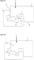
- FIGS 1A-1C An embodiment of the invention is shown during assembling in FIGS 1A-1C .
- the embodiment comprises a set of panels comprising a first panel 41 and a second panel 42, as shown in FIGS 3A and 3B , wherein a first edge 1 of the first panel 41 and a second edge 2 of the second panel 42 are configured to be locked together and assembled by a vertical displacement 27 of the second edge 2 of the second panel 42 relative to the first edge 1 of the first panel 41.
- the first edge 1 comprises a first locking element 4 which is configured to be able to cooperate with a first locking groove 5 at the second edge 2, for locking in a horizontal direction.
- the first edge 1 also comprises a tongue groove 7 which is configured to cooperate with a tongue 8 at the second edge 2, for locking in a vertical direction.
- the first locking element 4 comprises a first locking surface 10 which is configured to cooperate with a second locking surface 11 on the first locking groove 5, for locking in the horizontal and the vertical direction.
- the first locking surface 10 may be parallel or essentially parallel to the second locking surface 11.
- a first guiding surface 14 may be comprised on an upper part of the first edge 1, which first guiding surface 14 cooperates with a second guiding surface 15 on the lower edge of the tongue 8 during the vertical displacement 27.
- the tongue 8 on the second edge 2 may comprise an upper locking surface 16 which is configured to cooperate for locking in a vertical direction with a lower locking surface 17 of an upper lip 26 of the tongue groove 7.
- the locking element 4 may comprise a third guiding surface 18 and the locking groove 5 may comprise a fourth guiding surface 19. These features are configured to cooperate during the vertical displacement 27 of the second edge 2 relative to the first edge 1 for assembling the second edge 2 to the first edge 1, as shown in FIG 1B .
- the first guiding surface 14 may be parallel or essentially parallel to the second guiding surface 15.
- the third guiding surface 18 may be parallel or essentially parallel to the fourth guiding surface 19.
- the first and the second guiding surfaces 14,15 are configured to cooperate before the third and fourth guiding surfaces 18,19 during the vertical displacement.
- the second edge 2 may comprise a second locking element 22 and the first edge 1 may comprise a third locking groove 25 which are configured to cooperate for locking in a horizontal direction.
- the upper locking surface 16 is positioned above the second guiding surface 15.
- the first locking surface 10 is positioned below the third guiding surface 18.
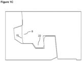
- FIG 1C A locked position of the first edge 1 and the second edge 2 is shown in FIG 1C .
- the first 1 and second edge 2 may be assembled by the vertical displacement 27.
- the second edge 2 may include a lower groove 29 on the underside of the second edge 2. This lower groove 29 may provide a space to allow the second edge 2 to bend in order to allow the upper locking surface 16 and the lower locking surface 17 to lock together with greater ease.
- the length of the second edge 2 is preferably shorter than the length of the first edge 1.
- the vertical and horizontal lockings may be an advantage, especially for panels with a locking in a resilient material.
- the multiple vertical lockings may decrease the risk of unlocking and a separation of the first 1 and second 2 edges.
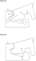
- FIGS 2A-2C An embodiment of the invention is shown during assembling in FIGS 2A-2C .
- the embodiment comprises a set of panels comprising a first panel 41 and a second panel 42, wherein a first edge 1 of the first panel 41 and a third edge 3 of the second panel 42 are configured to be locked together and assembled by an angling motion of the third edge 3 of the second panel 42 relative to the first edge 1 of the first panel 41.
- the first edge 1 comprises a first locking element 4 which is configured to be able to cooperate with a second locking groove 6 at the third edge 3, for locking in a horizontal direction.
- the first edge 1 also comprises a tongue groove 7 which is configured to cooperate with a tongue 9 at the third edge 3, for locking in a vertical direction.
- the first locking element 4 comprises a third locking surface 12 which is configured to cooperate with a fourth locking surface 13 on the second locking groove 6, for locking in the horizontal direction.
- the third locking surface 12 may be parallel or essentially parallel to the fourth locking surface 13.
- the tongue 9 may comprise an upper locking surface 20 which is configured to cooperate for locking in a vertical direction with the lower locking surface 17 of the upper lip 26 of the tongue groove 7.
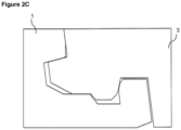
- the third edge 3 may comprise a third locking element 24 configured to cooperate with a third locking groove 25 on the first edge 1 for locking in a horizontal direction.
- the third edge 3 may be assembled to the first edge 1 by an angling motion, which is shown in FIGS 2A and 2B .
- the horizontal lockings as specified above may be an advantage, especially for panels with a locking in a resilient material.
- the multiple horizontal lockings may decrease the risk of unlocking and a separation of the first 1 and third 3 edges.
- a locked position of the first edge 1 and the third edge 3 is shown in FIG 2C .
- the first locking surface 10 is positioned below the third locking surface 12.
- the third locking surface 12 is positioned below the third guiding surface 18.
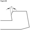
- FIGS 6A-6E Enlargements of the first locking element 4 are shown in FIGS 6A-6E .
- An angle 31 between the first 10 and third 12 locking surface may be within the range of about 5° to about 30°, preferably within the range of about 10° to about 25°, or preferably about 17°.
- An angle 32 between the third locking surface 12 and third guiding surface 18 may be within the range of about 10° to about 40°, preferably within the range of about 20° to about 30°, or preferably about 25°.
- An angle 33 between the first locking surface 10 and an upper surface of the first 41 or second 42 panel is within the range of about 70° to about 85°, preferably within the range of about 75° to about 80°, or preferably about 77°.
- An angle 34 between the third locking surface 12 and an upper surface of the first 41 or second 42 panel may be within the range of about 50° to about 85°, preferably within the range of about 60° to about 75°, or preferably about 67°.
- An angle 35 between the third guiding surface 18 and an upper surface of the first 41 or second 42 panel may be within the range of about 25° to about 60°, preferably within the range of about 35° to about 50°, or preferably about 42°.
- the set of panels according to embodiments of the present invention may provide an increased locking strength of the panels due to the multiple locking surfaces.
- An improved locking together of the panels may be critical for keeping the panels in position, also when being subject to forces by subject matter in motion on the panels.
- the set of panels according to embodiments of the present invention may also be easier to assemble compared to known sets of panels due to the guiding surfaces.
- An improved guiding may be critical for assembling panels having surfaces with a high friction and particularly, if the panel edges comprise a less elastic material. Without the improved guiding such panels may be difficult to assemble or the panels or part of the panel, e.g., the tongue may break during the assembling.
- the set of panels according to embodiments of the present invention also provide a more compact junction between panels and thereby a reduced amount of panel material going to waste.
- the set of panels according to embodiments of the present invention may be assembled in different patterns.
- One example is a herringbone pattern, wherein a first 41 and second 42 panel are assembled, as shown in FIGS 4A-4B .
- the second edge 2 of the second panel 42 is to be connected vertically to the first edge 1 of the first panel 41.
- FIGS 5A-5B Another example is a modular pattern, in which the panels are assembled parallel to each other, as shown in FIGS 5A-5B .
- assembling the panels in a modular pattern either only multiples of the first panel 41 or only multiples of the second panel 42 are to be connected to each other in each row of panels.
- the first edge 1 of a first panel 41 is connected to the third edge 3 of a first panel 41, or, alternatively, the first edge 1 of a second panel 42 is connected to the third edge 3 of a second panel 42.
- the first panel 41 may comprise, in a clockwise direction, the first edge 1, the first edge 1, the second edge 2, and the third edge 3, as shown in FIG 3A .
- the second panel 42 may comprise, in a clockwise direction, the second edge 2, the first edge 1, the first edge 1, and the third edge 3, as shown in FIG 3B .
- the first 41 panel and the second 42 panel may have a thickness in the range of about 3 mm to about 12 mm.
- the embodiments described above may be resilient panels.
- the resilient panels may comprise a core comprising thermoplastic material.
- the thermoplastic material may be foamed.
- the thermoplastic material may comprise polyvinyl chloride (PVC), polyester, polypropylene (PP), polyethylene (PE), polystyrene (PS), polyurethane (PU), polyethylene terephthalate (PET), polyacrylate, methacrylate, polycarbonate, polyvinyl butyral, polybutylene terephthalate, or a combination thereof.
- the core may be formed of several layers.
- the embodiments described above may comprise a decorative layer, such as a decorative foil comprising a thermoplastic material.
- the thermoplastic material of the decorative layer may be or comprise polyvinyl chloride (PVC), polyester, polypropylene (PP), polyethylene (PE), polystyrene (PS), polyurethane (PU), polyethylene terephthalate (PET), polyacrylate, methacrylate, polycarbonate, polyvinyl butyral, polybutylene terephthalate, or a combination thereof.
- the decorative foil is preferably printed, for example by direct printing, rotogravure, or digital printing.
- the embodiments described above may comprise a wear layer such as a film or foil.
- the wear layer may comprise thermoplastic material.
- the thermoplastic material may be polyvinyl chloride (PVC), polyester, polypropylene (PP), polyethylene (PE), polystyrene (PS), polyurethane (PU), polyethylene terephthalate (PET), polyacrylate, methacrylate, polycarbonate, polyvinyl butyral, polybutylene terephthalate, or a combination thereof.
- the embodiments described above may comprise a wood base core, such as HDF, MDF or plywood.
- the first panel and the second panel may be configured to be disassembled by downwardly rotating the first and/or the second panel.
Description
- The present disclosure relates to panels, such as floorboards, which are configured to be locked together.
- Panels are known that are configured to be assembled by a vertical displacement and to be locked together in a vertical direction and in a horizontal direction. Such panels are disclosed in e.g.,
WO 2014/182215 . A tongue and groove connection locks a first edge of a first panel to a second edge of the second panel. In addition, the first edge and the second edge include a locking element configured to cooperate with a locking groove for locking in the vertical and the horizontal direction. -
WO 2005/098163 relates to a panel element comprising two different locking elements. This type of panels, however, has the disadvantage that the junction between two panels needs to be long and that a lot of panel material thereby goes to waste when producing this type of panels. -
US 2004/177584 discloses floorboards for mechanical joining of floors in a herringbone pattern and in parallel rows with horizontal connectors which on the short sides have cooperating locking surfaces which are designed differently from the cooperating locking surfaces on the long sides.US 2008/295432 discloses a set of floor panels adapted to be locked to other panels mechanically, having an edge portion with a sidewardly open groove, in which groove a tongue formed as a separate part is received.WO 2017/187298 discloses a set of floor panels, which is suitable for forming a floor covering in herringbone pattern, wherein these floor panels are oblong rectangular and comprise a pair of long edges and a pair of short edges.KR 2009/0031347 WO 2007/118352 abstract) discloses a floor block comprising a projecting portion end with a projecting portion and a concave portion end with a concave portion. The projecting portion and the concave portion can be spliced in the following way: placing the projecting portion against the concave portion, then introducing the projecting portion into the concave portion by applying pressure to the projecting portion. - Embodiments of the present invention address a need to provide an easier assembling and/or an increased locking strength of the panels, which panels further enable laying in advanced patterns, such as in a herringbone pattern.
- It is an object of at least certain embodiments of the present invention to provide an improvement over the above described techniques and known art.
- A further object of at least certain embodiments of the present invention is to facilitate assembling of panels configured to be assembled by a vertical displacement or an angling motion and locked together in the vertical direction and the horizontal direction. A further object of at least certain embodiments of the present invention is to provide panels comprising only one locking element, but providing two different locking surfaces, enabling a more compact junction between panels and thereby a reduced amount of panel material going to waste.
- A further object of at least certain embodiments of the present invention is to provide panels configured to be able to be locked together in such a way that not only the long edges of the panels may be locked together, or the short edges may be locked together, but also that the short edges may be locked together with the long edges, enabling laying in advanced patterns, where one example is a herringbone pattern.
- At least some of these and other objects and advantages that may become apparent from the description have been achieved by the invention as defined in the appended claims, comprising a set of panels that include a first panel and a second panel, said first and second panel having a first, second and third edge. The first edge of the first panel is configured to be able to be locked together with both the second edge and the third edge, respectively, of the second panel. The first edge comprises a first locking element configured to be able to cooperate with a first locking groove at the second edge and a second locking groove at the third edge, respectively, for locking in a horizontal direction. The first edge further comprises a tongue groove configured to cooperate with a tongue at the second edge and a tongue at the third edge, respectively, for locking in a vertical direction. The first locking element comprises a first locking surface configured to cooperate with a second locking surface on the first locking groove for locking in the horizontal and the vertical direction. The first locking element comprises a third locking surface which is configured to cooperate with a fourth locking surface on the second locking groove for locking in the horizontal direction.
- An upper part of the first edge may comprise a first guiding surface and a lower edge of the tongue of the second edge may comprise a second guiding surface, configured to cooperate during a vertical displacement of the second edge relative to the first edge for assembling the second edge to the first edge.
- The tongue on the second edge may comprise an upper locking surface which is configured to cooperate for locking in a vertical direction with a lower locking surface at an upper lip of the tongue groove at the first edge.
- An upper part of the first locking element may comprise a third guiding surface and a lower edge of the first locking groove may comprise a fourth guiding surface, configured to cooperate during the vertical displacement of the second edge relative to the first edge for assembling the second edge to the first edge.
- The tongue at the third edge may comprise an upper locking surface which is configured to cooperate for locking in a vertical direction with the lower locking surface of the upper lip of the tongue groove at the first edge.
- An angle between the first and third locking surface is preferably within the range of about 5° to about 30°, preferably within the range of about 10° to about 25°, or preferably about 17°.
- An angle between the third locking surface and third guiding surface is preferably within the range of about 10° to about 40°, preferably within the range of about 20° to about 30°, or preferably about 25°.
- The second edge may comprise a second locking element and the first edge may comprise a third locking groove which are configured to cooperate for locking in a horizontal direction.
- The third edge may comprise a third locking element configured to cooperate with the third locking groove for locking in a horizontal direction.
- The length of the second edge may be shorter than the length of the first edge.
- The second edge of the second panel may be connected vertically to the first edge of the first panel.
- The first panel may comprise, in a clockwise direction, the first edge, the first edge, the second edge, and the third edge.
- The second panel may comprise, in a clockwise direction, the second edge, the first edge, the first edge, and the third edge.
- The third edge is configured to be assembled to the first edge by an angling motion.
- The first, second, and third edge of the first and second panel is preferably produced by mechanically cutting, such as milling.
- The locking surfaces and the guiding surfaces may comprise a material of the core of the first panel and/or the second panel.
- The first panel and the second panel may be resilient panels. The resilient panels may comprise a core comprising thermoplastic material. The thermoplastic material may be foamed.
- The thermoplastic material may comprise polyvinyl chloride (PVC), polyester, polypropylene (PP), polyethylene (PE), polystyrene (PS), polyurethane (PU), polyethylene terephthalate (PET), polyacrylate, methacrylate, polycarbonate, polyvinyl butyral, polybutylene terephthalate, or a combination thereof. The core may be formed of several layers.
- The first panel and the second panel may comprise a decorative layer, such as a decorative foil comprising a thermoplastic material. The thermoplastic material of the decorative layer may be or comprise polyvinyl chloride (PVC), polyester, polypropylene (PP), polyethylene (PE), polystyrene (PS), polyurethane (PU), polyethylene terephthalate (PET), polyacrylate, methacrylate, polycarbonate, polyvinyl butyral, polybutylene terephthalate, or a combination thereof. The decorative foil is preferably printed, for example by direct printing, rotogravure, or digital printing.
- The first panel and the second panel may comprise a wear layer such as a film or foil. The wear layer may comprise thermoplastic material. The thermoplastic material may be polyvinyl chloride (PVC), polyester, polypropylene (PP), polyethylene (PE), polystyrene (PS), polyurethane (PU), polyethylene terephthalate (PET), polyacrylate, methacrylate, polycarbonate, polyvinyl butyral, polybutylene terephthalate, or a combination thereof.
- Embodiments of the invention may be particularly advantageous for panels comprising guiding surfaces with higher friction and tongues comprising a less elastic thermoplastic material.
- The first and the second panel may comprise a wood-based core, such as HDF, MDF or plywood.
- The first panel and the second panel may be configured to be disassembled by downwardly rotating the first and/or the second panel.
- These and other aspects, features and advantages of which embodiments of the invention are capable of, will be apparent and elucidated from the following description of embodiments of the present invention, reference being made to the accompanying drawings, in which
-
FIGS 1A-1C show an embodiment of an assembling of an embodiment of a set of panels according to the invention, in which a first edge of a first panel and a second edge of a second panel are assembled. -
FIGS 2A-2C show an embodiment of an assembling of an embodiment of a set of panels according to the invention, in which a first edge of a first panel and a third edge of a second panel are assembled. -
FIG 3A shows an embodiment of a first panel according to the invention, comprising, in a clockwise direction starting from the edge to the right, the first edge, the first edge, the second edge, and the third edge. -
Fig 3B shows an embodiment of a second panel according to the invention, comprising, in a clockwise direction starting from the edge to the right, the second edge, the first edge, the first edge, and the third edge. -
FIGS 4A-4B show an embodiment of a set of panels according to the present invention, in which the panels are assembled in a herringbone pattern. -
FIGS 5A-5B show an embodiment in which panels according to the present invention are assembled in a modular pattern, i.e., parallel to each other. When assembling the panels in a modular pattern either only multiples of the first panel or only multiples of the second panel are to be connected to each other. -
FIGS 6A-6E show enlargements of the first locking element, illustrating angles between the different surfaces of the first locking element and also angles between the surfaces of the first locking element and an upper surface of the first or second panel. - Specific embodiments of the invention will now be described with reference to the accompanying drawings. This invention may, however, be embodied in many different forms and should not be construed as limited to the embodiments set forth herein; rather, these embodiments are provided so that this disclosure will be thorough and complete, and will fully convey the scope of the invention to those skilled in the art. The terminology used in the detailed description of the embodiments illustrated in the accompanying drawings is not intended to limit the invention. In the drawings, like numbers refer to like elements. When the word "about" is used in this specification in connection with a numerical value, it is intended that the associated numerical value include a tolerance of +/- 10% around the stated numerical value.
- An embodiment of the invention is shown during assembling in
FIGS 1A-1C . The embodiment comprises a set of panels comprising afirst panel 41 and asecond panel 42, as shown inFIGS 3A and 3B , wherein afirst edge 1 of thefirst panel 41 and asecond edge 2 of thesecond panel 42 are configured to be locked together and assembled by avertical displacement 27 of thesecond edge 2 of thesecond panel 42 relative to thefirst edge 1 of thefirst panel 41. - The
first edge 1 comprises afirst locking element 4 which is configured to be able to cooperate with afirst locking groove 5 at thesecond edge 2, for locking in a horizontal direction. Thefirst edge 1 also comprises atongue groove 7 which is configured to cooperate with atongue 8 at thesecond edge 2, for locking in a vertical direction. Further, thefirst locking element 4 comprises afirst locking surface 10 which is configured to cooperate with asecond locking surface 11 on thefirst locking groove 5, for locking in the horizontal and the vertical direction. - The
first locking surface 10 may be parallel or essentially parallel to thesecond locking surface 11. - A first guiding
surface 14 may be comprised on an upper part of thefirst edge 1, which first guidingsurface 14 cooperates with asecond guiding surface 15 on the lower edge of thetongue 8 during thevertical displacement 27. - The
tongue 8 on thesecond edge 2 may comprise anupper locking surface 16 which is configured to cooperate for locking in a vertical direction with alower locking surface 17 of anupper lip 26 of thetongue groove 7. - The locking
element 4 may comprise athird guiding surface 18 and the lockinggroove 5 may comprise afourth guiding surface 19. These features are configured to cooperate during thevertical displacement 27 of thesecond edge 2 relative to thefirst edge 1 for assembling thesecond edge 2 to thefirst edge 1, as shown inFIG 1B . - The
first guiding surface 14 may be parallel or essentially parallel to thesecond guiding surface 15. - The
third guiding surface 18 may be parallel or essentially parallel to the fourth guidingsurface 19. - The first and the second guiding surfaces 14,15 are configured to cooperate before the third and fourth guiding surfaces 18,19 during the vertical displacement.
- The
second edge 2 may comprise asecond locking element 22 and thefirst edge 1 may comprise athird locking groove 25 which are configured to cooperate for locking in a horizontal direction. - The
upper locking surface 16 is positioned above thesecond guiding surface 15. - The
first locking surface 10 is positioned below the third guidingsurface 18. - A locked position of the
first edge 1 and thesecond edge 2 is shown inFIG 1C . The first 1 andsecond edge 2 may be assembled by thevertical displacement 27. - The
second edge 2 may include alower groove 29 on the underside of thesecond edge 2. Thislower groove 29 may provide a space to allow thesecond edge 2 to bend in order to allow theupper locking surface 16 and thelower locking surface 17 to lock together with greater ease. - The length of the
second edge 2 is preferably shorter than the length of thefirst edge 1. - The vertical and horizontal lockings may be an advantage, especially for panels with a locking in a resilient material. The multiple vertical lockings may decrease the risk of unlocking and a separation of the first 1 and second 2 edges.
- An embodiment of the invention is shown during assembling in
FIGS 2A-2C . The embodiment comprises a set of panels comprising afirst panel 41 and asecond panel 42, wherein afirst edge 1 of thefirst panel 41 and athird edge 3 of thesecond panel 42 are configured to be locked together and assembled by an angling motion of thethird edge 3 of thesecond panel 42 relative to thefirst edge 1 of thefirst panel 41. - The
first edge 1 comprises afirst locking element 4 which is configured to be able to cooperate with asecond locking groove 6 at thethird edge 3, for locking in a horizontal direction. - The
first edge 1 also comprises atongue groove 7 which is configured to cooperate with atongue 9 at thethird edge 3, for locking in a vertical direction. Further, thefirst locking element 4 comprises athird locking surface 12 which is configured to cooperate with afourth locking surface 13 on thesecond locking groove 6, for locking in the horizontal direction. - The
third locking surface 12 may be parallel or essentially parallel to thefourth locking surface 13. - The
tongue 9 may comprise anupper locking surface 20 which is configured to cooperate for locking in a vertical direction with thelower locking surface 17 of theupper lip 26 of thetongue groove 7. - The
third edge 3 may comprise athird locking element 24 configured to cooperate with athird locking groove 25 on thefirst edge 1 for locking in a horizontal direction. - The
third edge 3 may be assembled to thefirst edge 1 by an angling motion, which is shown inFIGS 2A and 2B . - The horizontal lockings as specified above may be an advantage, especially for panels with a locking in a resilient material. The multiple horizontal lockings may decrease the risk of unlocking and a separation of the first 1 and third 3 edges.
- A locked position of the
first edge 1 and thethird edge 3 is shown inFIG 2C . - The
first locking surface 10 is positioned below thethird locking surface 12. - The
third locking surface 12 is positioned below the third guidingsurface 18. - Enlargements of the
first locking element 4 are shown inFIGS 6A-6E . - An
angle 31 between the first 10 and third 12 locking surface may be within the range of about 5° to about 30°, preferably within the range of about 10° to about 25°, or preferably about 17°. - An
angle 32 between thethird locking surface 12 and third guidingsurface 18 may be within the range of about 10° to about 40°, preferably within the range of about 20° to about 30°, or preferably about 25°. - An
angle 33 between thefirst locking surface 10 and an upper surface of the first 41 or second 42 panel is within the range of about 70° to about 85°, preferably within the range of about 75° to about 80°, or preferably about 77°. - An
angle 34 between thethird locking surface 12 and an upper surface of the first 41 or second 42 panel may be within the range of about 50° to about 85°, preferably within the range of about 60° to about 75°, or preferably about 67°. - An
angle 35 between the third guidingsurface 18 and an upper surface of the first 41 or second 42 panel may be within the range of about 25° to about 60°, preferably within the range of about 35° to about 50°, or preferably about 42°. - The set of panels according to embodiments of the present invention may provide an increased locking strength of the panels due to the multiple locking surfaces. An improved locking together of the panels may be critical for keeping the panels in position, also when being subject to forces by subject matter in motion on the panels.
- The set of panels according to embodiments of the present invention may also be easier to assemble compared to known sets of panels due to the guiding surfaces. An improved guiding may be critical for assembling panels having surfaces with a high friction and particularly, if the panel edges comprise a less elastic material. Without the improved guiding such panels may be difficult to assemble or the panels or part of the panel, e.g., the tongue may break during the assembling. The set of panels according to embodiments of the present invention also provide a more compact junction between panels and thereby a reduced amount of panel material going to waste.
- The set of panels according to embodiments of the present invention may be assembled in different patterns. One example is a herringbone pattern, wherein a first 41 and second 42 panel are assembled, as shown in
FIGS 4A-4B . When assembling the panels in a herringbone pattern, thesecond edge 2 of thesecond panel 42 is to be connected vertically to thefirst edge 1 of thefirst panel 41. - Another example is a modular pattern, in which the panels are assembled parallel to each other, as shown in
FIGS 5A-5B . When assembling the panels in a modular pattern either only multiples of thefirst panel 41 or only multiples of thesecond panel 42 are to be connected to each other in each row of panels. When assembling the panels in a modular pattern, thefirst edge 1 of afirst panel 41 is connected to thethird edge 3 of afirst panel 41, or, alternatively, thefirst edge 1 of asecond panel 42 is connected to thethird edge 3 of asecond panel 42. - The
first panel 41 may comprise, in a clockwise direction, thefirst edge 1, thefirst edge 1, thesecond edge 2, and thethird edge 3, as shown inFIG 3A . - The
second panel 42 may comprise, in a clockwise direction, thesecond edge 2, thefirst edge 1, thefirst edge 1, and thethird edge 3, as shown inFIG 3B . - The first 41 panel and the second 42 panel may have a thickness in the range of about 3 mm to about 12 mm.
- The embodiments described above may be resilient panels. The resilient panels may comprise a core comprising thermoplastic material. The thermoplastic material may be foamed.
- The thermoplastic material may comprise polyvinyl chloride (PVC), polyester, polypropylene (PP), polyethylene (PE), polystyrene (PS), polyurethane (PU), polyethylene terephthalate (PET), polyacrylate, methacrylate, polycarbonate, polyvinyl butyral, polybutylene terephthalate, or a combination thereof. The core may be formed of several layers.
- The embodiments described above may comprise a decorative layer, such as a decorative foil comprising a thermoplastic material. The thermoplastic material of the decorative layer may be or comprise polyvinyl chloride (PVC), polyester, polypropylene (PP), polyethylene (PE), polystyrene (PS), polyurethane (PU), polyethylene terephthalate (PET), polyacrylate, methacrylate, polycarbonate, polyvinyl butyral, polybutylene terephthalate, or a combination thereof. The decorative foil is preferably printed, for example by direct printing, rotogravure, or digital printing.
- The embodiments described above may comprise a wear layer such as a film or foil. The wear layer may comprise thermoplastic material. The thermoplastic material may be polyvinyl chloride (PVC), polyester, polypropylene (PP), polyethylene (PE), polystyrene (PS), polyurethane (PU), polyethylene terephthalate (PET), polyacrylate, methacrylate, polycarbonate, polyvinyl butyral, polybutylene terephthalate, or a combination thereof.
- The embodiments described above may comprise a wood base core, such as HDF, MDF or plywood.
- The first panel and the second panel may be configured to be disassembled by downwardly rotating the first and/or the second panel.
Claims (12)
- A set of panels comprising a first panel (41) and a second panel (42), said first (41) and second (42) panel each having a first edge (1), a second edge (2) and a third (3) edge and wherein the first edge (1) of the first panel (41) is configured to be able to be locked together with both the second (2) edge and the third (3) edge, respectively, of the second panel (42),wherein the first edge (1) comprises a first locking element (4) configured to be able to cooperate with a first locking groove (5) at the second edge (2) and a second locking groove (6) at the third edge (3), respectively, for locking in a horizontal direction,wherein the first edge (1) of the first panel (41) and the second edge (2) of the second panel (42) are configured to be locked together and assembled by a vertical displacement (27) of the second edge (2) of the second panel (42) relative to the first edge (1) of the first panel (41),wherein the first edge (1) of the first panel (41) and the third edge (3) of the second panel (42) are configured to be locked together and assembled by an angling motion of the third edge (3) of the second panel (42) relative to the first edge (1) of the first panel (41),wherein the first locking element (4) comprises a first locking surface (10) configured to cooperate with a second locking surface (11) on the first locking groove (5),wherein the first locking element (4) comprises a third locking surface (12) which is configured to cooperate with a fourth locking surface (13) on the second locking groove (6) for locking in the horizontal direction,characterised in thatthe second edge (2) is provided with a tongue (8) and the third edge (3) is provided with a tongue (9), andthe first edge (1) further comprises a tongue groove (7) configured to cooperate with the tongue (8) at the second edge (2) and the tongue (9) at the third edge (3), respectively, for locking in a vertical direction,the configuration of the first locking surface (10) to cooperate with a second locking surface (11) on the first locking groove (5) is for locking in the horizontal and the vertical direction, and in thatan angle (33) between the first locking surface (10) and an upper surface of the first (41) or second (42) panel is within the range of about 70° to about 85°.
- The set of panels according to claim 1, wherein an upper part of the first edge (1) comprises a first guiding surface (14) and a lower edge of the tongue (8) of the second edge (2) comprises a second guiding surface (15), configured to cooperate during a vertical displacement (27) of the second edge (2) relative the first edge (1) for assembling the second edge (2) to the first edge (1).
- The set of panels according to claim 1 or 2, wherein the tongue (8) on the second edge (2) comprises an upper locking surface (16) which is configured to cooperate for locking in a vertical direction with a lower locking surface (17) of an upper lip (26) of the tongue groove (7).
- The set of panels according to any of the claims 1 to 3, wherein an upper part of the first locking element (4) comprises a third guiding surface (18) and a lower edge of the first locking groove (5) comprises a fourth guiding surface (19), configured to cooperate during the vertical displacement (27) of the second edge (2) relative the first edge (1) for assembling the second edge (2) to the first edge (1).
- The set of panels according to any one of the claims 1 to 4, wherein the tongue (9) comprises an upper locking surface (20) which is configured to cooperate for locking in a vertical direction with the lower locking surface (17) of the upper lip (26) of the tongue groove (7).
- The set of panels according to any one of the claims 1 to 5, wherein an angle (31) between the first (10) and third (12) locking surface is within the range of about 5° to about 30°, preferably within the range of about 10° to about 25°, or preferably about 17°.
- The set of panels according to any one of the claims 4 to 6, wherein an angle (32) between the third locking surface (12) and third guiding surface (18) is within the range of about 10° to about 40°, preferably within the range of about 20° to about 30°, or preferably about 25°.
- The set of panels according to any one of the previous claims, wherein the second edge (2) comprises a second locking element (22) and the first edge (1) comprises a third locking groove (25), and wherein the second locking element and third locking groove are configured to cooperate for locking in a horizontal direction.
- The set of panels according to any one of the previous claims, wherein the third edge (3) comprises a third locking element (24) configured to cooperate with the third locking groove (25) for locking in a horizontal direction.
- The set of panels according to claim any one of the previous claims, wherein the length of the second edge (2) is shorter than the length of the first edge (1).
- The set of panels according to any one of the previous claims, wherein the first panel (41) comprises, in a clockwise direction, the first edge (1), the first edge (1), the second edge (2), and the third edge (3).
- The set of panels according to any one of the previous claims, wherein the second panel (42) comprises, in a clockwise direction, the second edge (2), the first edge (1), the first edge (1), and the third edge (3).
Priority Applications (2)
| Application Number | Priority Date | Filing Date | Title |
|---|---|---|---|
| EP23172113.5A EP4234837A1 (en) | 2018-01-09 | 2018-12-14 | Set of panels |
| HRP20230520TT HRP20230520T1 (en) | 2018-01-09 | 2018-12-14 | Set of panels |
Applications Claiming Priority (2)
| Application Number | Priority Date | Filing Date | Title |
|---|---|---|---|
| SE1850026 | 2018-01-09 | ||
| PCT/SE2018/051322 WO2019139520A1 (en) | 2018-01-09 | 2018-12-14 | Set of panels |
Related Child Applications (1)
| Application Number | Title | Priority Date | Filing Date |
|---|---|---|---|
| EP23172113.5A Division EP4234837A1 (en) | 2018-01-09 | 2018-12-14 | Set of panels |
Publications (3)
| Publication Number | Publication Date |
|---|---|
| EP3737802A1 EP3737802A1 (en) | 2020-11-18 |
| EP3737802A4 EP3737802A4 (en) | 2021-10-13 |
| EP3737802B1 true EP3737802B1 (en) | 2023-05-10 |
Family
ID=67140530
Family Applications (2)
| Application Number | Title | Priority Date | Filing Date |
|---|---|---|---|
| EP23172113.5A Pending EP4234837A1 (en) | 2018-01-09 | 2018-12-14 | Set of panels |
| EP18899265.5A Active EP3737802B1 (en) | 2018-01-09 | 2018-12-14 | Set of panels |
Family Applications Before (1)
| Application Number | Title | Priority Date | Filing Date |
|---|---|---|---|
| EP23172113.5A Pending EP4234837A1 (en) | 2018-01-09 | 2018-12-14 | Set of panels |
Country Status (16)
| Country | Link |
|---|---|
| US (2) | US10808410B2 (en) |
| EP (2) | EP4234837A1 (en) |
| JP (1) | JP7379341B2 (en) |
| KR (1) | KR102556891B1 (en) |
| CN (1) | CN111556917A (en) |
| AU (1) | AU2018400651A1 (en) |
| BR (1) | BR112020013765B1 (en) |
| CA (1) | CA3086053A1 (en) |
| EA (1) | EA039273B1 (en) |
| ES (1) | ES2949620T3 (en) |
| HR (1) | HRP20230520T1 (en) |
| HU (1) | HUE062135T2 (en) |
| PH (1) | PH12020550999A1 (en) |
| PL (1) | PL3737802T3 (en) |
| PT (1) | PT3737802T (en) |
| WO (1) | WO2019139520A1 (en) |
Families Citing this family (27)
| Publication number | Priority date | Publication date | Assignee | Title |
|---|---|---|---|---|
| US8028486B2 (en) | 2001-07-27 | 2011-10-04 | Valinge Innovation Ab | Floor panel with sealing means |
| SE530653C2 (en) | 2006-01-12 | 2008-07-29 | Vaelinge Innovation Ab | Moisture-proof floor board and floor with an elastic surface layer including a decorative groove |
| US8365499B2 (en) | 2009-09-04 | 2013-02-05 | Valinge Innovation Ab | Resilient floor |
| US11725395B2 (en) | 2009-09-04 | 2023-08-15 | Välinge Innovation AB | Resilient floor |
| CA3209449A1 (en) | 2010-01-11 | 2011-07-14 | Valinge Innovation Ab | Floor covering with interlocking design |
| EP3656944A1 (en) | 2013-03-25 | 2020-05-27 | Välinge Innovation AB | Floorboards provided with a mechanical locking system and a method to produce such a locking system |
| CN106536214A (en) | 2014-07-16 | 2017-03-22 | 瓦林格创新股份有限公司 | Method to produce a thermoplastic wear resistant foil |
| WO2016029255A1 (en) | 2014-08-29 | 2016-03-03 | Kell Richard William | Vertical joint system for a surface covering panel |
| RU2702563C2 (en) | 2015-01-14 | 2019-10-08 | Велинге Инновейшн Аб | Method of obtaining wear-resistant layer with different levels of gloss |
| EP3390744A4 (en) | 2015-12-17 | 2019-07-31 | Välinge Innovation AB | A method for producing a mechanical locking system for panels |
| BR112019005906B1 (en) | 2016-09-30 | 2023-02-14 | Välinge Innovation AB | SET OF PANELS ASSEMBLED BY VERTICAL DISPLACEMENT AND LOCKED IN VERTICAL AND HORIZONTAL DIRECTIONS |
| US10808410B2 (en) | 2018-01-09 | 2020-10-20 | Valinge Innovation Ab | Set of panels |
| WO2019138365A1 (en) | 2018-01-11 | 2019-07-18 | Flooring Industries Limited, Sarl | Set of floor panels and method for installing this set of floor panels |
| SE542114C2 (en) * | 2018-01-27 | 2020-02-25 | Ipendor Ab | Joining system for floor panels |
| NL2021885B1 (en) * | 2018-10-26 | 2020-05-13 | I4F Licensing Nv | Multi-purpose tile system, tile covering, and tile |
| BE1026806B1 (en) * | 2018-11-27 | 2020-06-30 | Flooring Ind Ltd Sarl | Panel and method of manufacturing such panel |
| NL2022114B1 (en) * | 2018-12-03 | 2020-06-30 | I4F Licensing Nv | Decorative panel, and decorative floor covering consisting of said panels |
| MX2021006620A (en) * | 2018-12-05 | 2021-09-21 | I4F Licensing Nv | Decorative panel, and decorative floor covering consisting of said panels. |
| FR3090711B1 (en) * | 2018-12-21 | 2022-02-04 | Gerflor | PANEL FOR CREATING A LOOSE-LAYING FLOOR COVERING |
| EP3708739B1 (en) * | 2019-03-12 | 2021-02-17 | Flooring Technologies Ltd. | Hard floor panel for floating installation forming a floor |
| EP3798385A1 (en) | 2019-09-24 | 2021-03-31 | Välinge Innovation AB | Building panel |
| EP3798386A1 (en) * | 2019-09-24 | 2021-03-31 | Välinge Innovation AB | Set of panels with mechanically locking edges |
| IT202000001453A1 (en) | 2020-01-24 | 2021-07-24 | Pta Srl | SYSTEM OF RADIANT PANELS OR MODULAR SOLAR PANELS |
| NL2026189B1 (en) * | 2020-07-31 | 2022-04-04 | I4F Licensing Nv | Panel suitable as a floor, ceiling or wall covering, and covering for a floor, ceiling or wall, which is constituted by a multitude of such panel |
| BR112023000155A2 (en) * | 2020-07-31 | 2023-02-07 | I4F Licensing Nv | PANEL SUITABLE AS FLOOR, CEILING OR WALL PANEL AND COVERING FOR FLOOR, CEILING OR WALL |
| NL2028776B1 (en) * | 2021-07-19 | 2023-01-25 | I4F Licensing Nv | Multi-purpose tile system, tile covering, and tile |
| BE1029978B1 (en) * | 2021-12-02 | 2023-07-03 | Flooring Ind Ltd Sarl | Decorative panel. |
Family Cites Families (327)
| Publication number | Priority date | Publication date | Assignee | Title |
|---|---|---|---|---|
| US1787027A (en) * | 1929-02-20 | 1930-12-30 | Wasleff Alex | Herringbone flooring |
| US3120083A (en) | 1960-04-04 | 1964-02-04 | Bigelow Sanford Inc | Carpet or floor tiles |
| FR1293043A (en) | 1961-03-27 | 1962-05-11 | Piraud Plastiques Ets | Flooring Tile |
| US3247638A (en) | 1963-05-22 | 1966-04-26 | James W Fair | Interlocking tile carpet |
| US3538665A (en) | 1968-04-15 | 1970-11-10 | Bauwerke Ag | Parquet flooring |
| SE0001325L (en) | 2000-04-10 | 2001-06-25 | Valinge Aluminium Ab | Locking systems for joining floorboards and floorboards provided with such locking systems and floors formed from such floorboards |
| SE0002342L (en) | 2000-06-22 | 2001-07-16 | Tarkett Sommer Ab | Floor board with connecting means |
| US3760547A (en) | 1969-08-13 | 1973-09-25 | J Brenneman | Spline and seat connector assemblies |
| NL7102276A (en) | 1970-02-20 | 1971-08-24 | ||
| US3694983A (en) | 1970-05-19 | 1972-10-03 | Pierre Jean Couquet | Pile or plastic tiles for flooring and like applications |
| GB1385375A (en) | 1971-02-26 | 1975-02-26 | Sanwa Kako Co | Floor covering unit |
| DE2111324C3 (en) | 1971-03-10 | 1979-07-05 | Migua-Mitteldeutsche Gummi Und Asbestgesellschaft Hammerschmidt & Co, 5628 Heiligenhaus | Device for sealing joints between components |
| DE2251762A1 (en) | 1972-10-21 | 1974-05-02 | Geb Walter Gisela Weber | FLOORING |
| GB1430423A (en) | 1973-05-09 | 1976-03-31 | Gkn Sankey Ltd | Joint structure |
| US3919820A (en) | 1973-12-13 | 1975-11-18 | Johns Manville | Wall structure and device for sealing thereof |
| US4172169A (en) | 1976-10-01 | 1979-10-23 | Nairn Floors Limited | Floor or wall coverings |
| US4113399A (en) | 1977-03-02 | 1978-09-12 | Hansen Sr Wray C | Knob spring |
| US4176210A (en) | 1977-04-12 | 1979-11-27 | Gaf Corporation | Process for making urethane coated decorative sheet-type covering material |
| ES230786Y (en) | 1977-08-27 | 1978-03-16 | GASKET FOR ROOF PANELS. | |
| US4180615A (en) | 1977-11-07 | 1979-12-25 | Gaf Corporation | Vinyl tile and production thereof |
| US4187131A (en) | 1978-02-21 | 1980-02-05 | Congoleum Corporation | Resinous polymer sheet materials having selective, surface decorative effects and methods of making the same |
| US4313866A (en) | 1978-12-26 | 1982-02-02 | Monsanto Company | Plasticizers for vinyl chloride polymers |
| US4426820A (en) | 1979-04-24 | 1984-01-24 | Heinz Terbrack | Panel for a composite surface and a method of assembling same |
| US4333987A (en) | 1979-12-19 | 1982-06-08 | Harold Kwart | Methods for bonding dissimilar synthetic polymeric materials and the products involved in and resulting from such methods |
| US4423178A (en) | 1980-05-19 | 1983-12-27 | Monsanto Company | Plasticizers for vinyl chloride polymers |
| US4393187A (en) | 1982-06-23 | 1983-07-12 | Congoleum Corporation | Stain resistant, abrasion resistant polyurethane coating composition, substrate coated therewith and production thereof |
| US4489115A (en) | 1983-02-16 | 1984-12-18 | Superturf, Inc. | Synthetic turf seam system |
| DK149498C (en) | 1983-04-07 | 1986-12-01 | Inter Ikea As | CLOTHING OF BREADS FOR EX. FLOORS OR PANELS |
| US4512131A (en) | 1983-10-03 | 1985-04-23 | Laramore Larry W | Plank-type building system |
| US4507188A (en) | 1983-12-21 | 1985-03-26 | Thiokol Corporation | Ultraviolet curable formulations containing urethane acrylate monomers |
| US4614680A (en) | 1984-04-16 | 1986-09-30 | Armstrong World Industries, Inc. | Decorative product |
| JPS60255843A (en) | 1984-05-31 | 1985-12-17 | Toyo Linoleum Mfg Co Ltd:The | Vinyl tile |
| DK155616C (en) | 1984-09-25 | 1989-09-04 | Eminent Plast | GRID OR MEASUREMENT ELEMENT FOR THE CREATION OF A FLOOR COVERING BY CONNECTION WITH SIMILAR ELEMENTS |
| IT1183846B (en) | 1985-05-20 | 1987-10-22 | Mondo Rubber Spa | COATING OF SYNTHETIC MATERIAL IN THE FORM OF TILES AND RELATED MANUFACTURING PROCEDURE |
| DE3622602A1 (en) | 1986-07-05 | 1988-01-14 | Basf Ag | BINDERS FOR TRANSFER PRINTING |
| US5007222A (en) | 1988-11-14 | 1991-04-16 | Raymond Harry W | Foamed building panel including an internally mounted stud |
| US5112671A (en) | 1989-04-13 | 1992-05-12 | Armstrong World Industries, Inc. | Tile product having multiple levels of height, multiple levels of gloss and mortar-line surround |
| US5148850A (en) | 1989-06-28 | 1992-09-22 | Paneltech Ltd. | Weatherproof continuous hinge connector for articulated vehicular overhead doors |
| US5162141A (en) | 1990-12-17 | 1992-11-10 | Armstrong World Industries, Inc. | Polymeric sheet having an incompatible ink permanently bonded thereto |
| US5182892A (en) | 1991-08-15 | 1993-02-02 | Louisiana-Pacific Corporation | Tongue and groove board product |
| US5458953A (en) | 1991-09-12 | 1995-10-17 | Mannington Mills, Inc. | Resilient floor covering and method of making same |
| US5344700A (en) | 1992-03-27 | 1994-09-06 | Aliquot, Ltd. | Structural panels and joint connector arrangement therefor |
| SE9301595L (en) | 1993-05-10 | 1994-10-17 | Tony Pervan | Grout for thin liquid hard floors |
| US7121059B2 (en) | 1994-04-29 | 2006-10-17 | Valinge Innovation Ab | System for joining building panels |
| US20020178674A1 (en) | 1993-05-10 | 2002-12-05 | Tony Pervan | System for joining a building board |
| JPH0748879A (en) | 1993-08-05 | 1995-02-21 | Takeshige Shimonohara | Connecting method and connecting structure for member |
| US5441677A (en) | 1993-09-01 | 1995-08-15 | Hi-Tech Floors, Inc. | Method of making high gloss, hardened concrete floors |
| US5380794A (en) | 1993-11-02 | 1995-01-10 | Monsanto Company | Polyvinyl butyral tackifier for vinyl chloride polymer compositions |
| JP3363976B2 (en) | 1993-12-24 | 2003-01-08 | ミサワホーム株式会社 | Construction structure of flooring |
| JP3461569B2 (en) | 1994-05-02 | 2003-10-27 | 大建工業株式会社 | Floor material |
| US5465546A (en) | 1994-05-04 | 1995-11-14 | Buse; Dale C. | Portable dance floor |
| KR0147425B1 (en) | 1994-07-07 | 1998-11-02 | 김주용 | Tetra ethyl otho silicate process equipment |
| JP3167866B2 (en) | 1994-09-02 | 2001-05-21 | ミサワホーム株式会社 | Flooring structure of flooring material |
| US7131242B2 (en) | 1995-03-07 | 2006-11-07 | Pergo (Europe) Ab | Flooring panel or wall panel and use thereof |
| SE9500810D0 (en) | 1995-03-07 | 1995-03-07 | Perstorp Flooring Ab | Floor tile |
| US5618602A (en) | 1995-03-22 | 1997-04-08 | Wilsonart Int Inc | Articles with tongue and groove joint and method of making such a joint |
| US5670237A (en) | 1995-06-07 | 1997-09-23 | Mannington Mills, Inc. | Method for making a surface covering product and products resulting from said method |
| US5630304A (en) | 1995-12-28 | 1997-05-20 | Austin; John | Adjustable interlock floor tile |
| JP3954673B2 (en) | 1996-11-01 | 2007-08-08 | 株式会社ヤマックス | Joint for water stop of concrete joints |
| BE1010487A6 (en) | 1996-06-11 | 1998-10-06 | Unilin Beheer Bv | FLOOR COATING CONSISTING OF HARD FLOOR PANELS AND METHOD FOR MANUFACTURING SUCH FLOOR PANELS. |
| US5950389A (en) | 1996-07-02 | 1999-09-14 | Porter; William H. | Splines for joining panels |
| AU4303997A (en) | 1996-10-18 | 1998-05-15 | Variform Oy | Protective structure |
| US5694730A (en) | 1996-10-25 | 1997-12-09 | Noranda Inc. | Spline for joining boards |
| US6291078B1 (en) | 1997-10-22 | 2001-09-18 | Mannington Mills, Inc. | Surface coverings containing aluminum oxide |
| US5797237A (en) | 1997-02-28 | 1998-08-25 | Standard Plywoods, Incorporated | Flooring system |
| AT405560B (en) | 1997-06-18 | 1999-09-27 | Kaindl M | ARRANGEMENT OF COMPONENTS AND COMPONENTS |
| IT237576Y1 (en) | 1997-07-11 | 2000-09-13 | Unifor Spa | PERFECTED CONNECTION SYSTEM BETWEEN MODULAR PANELS |
| US6139945A (en) | 1997-11-25 | 2000-10-31 | Premark Rwp Holdings, Inc. | Polymeric foam substrate and its use as in combination with decorative surfaces |
| US6345481B1 (en) | 1997-11-25 | 2002-02-12 | Premark Rwp Holdings, Inc. | Article with interlocking edges and covering product prepared therefrom |
| DE19854475B4 (en) | 1997-11-25 | 2006-06-14 | Premark RWP Holdings, Inc., Wilmington | Locking area coverage product |
| US6324809B1 (en) | 1997-11-25 | 2001-12-04 | Premark Rwp Holdings, Inc. | Article with interlocking edges and covering product prepared therefrom |
| US6173548B1 (en) | 1998-05-20 | 2001-01-16 | Douglas J. Hamar | Portable multi-section activity floor and method of manufacture and installation |
| US7386963B2 (en) | 1998-06-03 | 2008-06-17 | Valinge Innovation Ab | Locking system and flooring board |
| SE512290C2 (en) | 1998-06-03 | 2000-02-28 | Valinge Aluminium Ab | Locking system for mechanical joining of floorboards and floorboard provided with the locking system |
| BE1012141A6 (en) | 1998-07-24 | 2000-05-02 | Unilin Beheer Bv | FLOOR COVERING, FLOOR PANEL THEREFOR AND METHOD for the realization of such floor panel. |
| SE514645C2 (en) | 1998-10-06 | 2001-03-26 | Perstorp Flooring Ab | Floor covering material comprising disc-shaped floor elements intended to be joined by separate joint profiles |
| SE515789C2 (en) | 1999-02-10 | 2001-10-08 | Perstorp Flooring Ab | Floor covering material comprising floor elements which are intended to be joined vertically |
| DE19851200C1 (en) | 1998-11-06 | 2000-03-30 | Kronotex Gmbh Holz Und Kunstha | Floor panel has a tongue and groove joint between panels with additional projections and recesses at the underside of the tongue and the lower leg of the groove for a sealed joint with easy laying |
| FR2785633B1 (en) | 1998-11-09 | 2001-02-09 | Valerie Roy | COVERING PANEL FOR PARQUET, WOODEN PANEL OR THE LIKE |
| FI982525A0 (en) | 1998-11-23 | 1998-11-23 | Variform Oy | Security arrangement |
| IT1311220B1 (en) | 1999-04-20 | 2002-03-04 | Patt Srl | SLAT FLOOR AND METHOD FOR ITS INSTALLATION |
| SE517478C2 (en) | 1999-04-30 | 2002-06-11 | Valinge Aluminium Ab | Locking system for mechanical hoisting of floorboards, floorboard provided with the locking system and method for producing mechanically foldable floorboards |
| US6233899B1 (en) | 1999-05-21 | 2001-05-22 | David N. Nystrom | Apparatus and methods for installing tongue-and-groove materials |
| CA2377960C (en) | 1999-06-24 | 2007-12-04 | Flexiteek International A/S | Shape conforming surface covering |
| ATE222634T1 (en) | 1999-06-30 | 2002-09-15 | Akzenta Paneele & Profile Gmbh | PANEL AND FASTENING SYSTEM FOR PANELS |
| DE29911462U1 (en) | 1999-07-02 | 1999-11-18 | Akzenta Paneele & Profile Gmbh | Fastening system for panels |
| SE517009C2 (en) | 1999-07-05 | 2002-04-02 | Perstorp Flooring Ab | Floor element with controls |
| US7614197B2 (en) | 1999-11-08 | 2009-11-10 | Premark Rwp Holdings, Inc. | Laminate flooring |
| US6761008B2 (en) | 1999-12-14 | 2004-07-13 | Mannington Mills, Inc. | Connecting system for surface coverings |
| US6617009B1 (en) | 1999-12-14 | 2003-09-09 | Mannington Mills, Inc. | Thermoplastic planks and methods for making the same |
| US7763345B2 (en) | 1999-12-14 | 2010-07-27 | Mannington Mills, Inc. | Thermoplastic planks and methods for making the same |
| US7169460B1 (en) | 1999-12-14 | 2007-01-30 | Mannington Mills, Inc. | Thermoplastic planks and methods for making the same |
| WO2001045915A1 (en) | 1999-12-20 | 2001-06-28 | Polymer Sheet Applications Inc. | Method and apparatus for forming composite material and composite material therefrom |
| US6332733B1 (en) | 1999-12-23 | 2001-12-25 | Hamberger Industriewerke Gmbh | Joint |
| EP1157176B1 (en) | 1999-12-27 | 2003-10-22 | Kronospan Technical Company Ltd. | Panels with coupling means |
| DE10001076C1 (en) | 2000-01-13 | 2001-10-04 | Huelsta Werke Huels Kg | Panel element to construct floor covering; has groove and spring on opposite longitudinal sides and has groove and tongue on opposite end faces, to connect and secure adjacent panel elements |
| US6399670B1 (en) | 2000-01-21 | 2002-06-04 | Congoleum Corporation | Coating having macroscopic texture and process for making same |
| SE517183C2 (en) | 2000-01-24 | 2002-04-23 | Valinge Aluminium Ab | Locking system for mechanical joining of floorboards, floorboard provided with the locking system and method for making such floorboards |
| SE522860C2 (en) | 2000-03-10 | 2004-03-09 | Pergo Europ Ab | Vertically joined floor elements comprising a combination of different floor elements |
| SE518184C2 (en) | 2000-03-31 | 2002-09-03 | Perstorp Flooring Ab | Floor covering material comprising disc-shaped floor elements which are joined together by means of interconnecting means |
| US6363677B1 (en) | 2000-04-10 | 2002-04-02 | Mannington Mills, Inc. | Surface covering system and methods of installing same |
| US6553724B1 (en) | 2000-05-05 | 2003-04-29 | Robert A. Bigler | Panel and trade show booth made therefrom |
| DE20008708U1 (en) | 2000-05-16 | 2000-09-14 | Kronospan Tech Co Ltd | Panels with coupling agents |
| BE1013569A3 (en) | 2000-06-20 | 2002-04-02 | Unilin Beheer Bv | Floor covering. |
| DE10031639C2 (en) | 2000-06-29 | 2002-08-14 | Hw Ind Gmbh & Co Kg | Floor plate |
| US6546691B2 (en) | 2000-12-13 | 2003-04-15 | Kronospan Technical Company Ltd. | Method of laying panels |
| US20030110720A1 (en) | 2000-12-22 | 2003-06-19 | Berard Raymond A. | Padded raised flooring panels and coverings |
| DE10064280C1 (en) | 2000-12-22 | 2002-10-10 | Huelsta Werke Huels Kg | Panel for interior construction and method for creating new walls of a room or for cladding existing surfaces of a room |
| US6851241B2 (en) | 2001-01-12 | 2005-02-08 | Valinge Aluminium Ab | Floorboards and methods for production and installation thereof |
| US6769218B2 (en) | 2001-01-12 | 2004-08-03 | Valinge Aluminium Ab | Floorboard and locking system therefor |
| DE10101912C1 (en) | 2001-01-16 | 2002-03-14 | Johannes Schulte | Rectangular floor panel laying method uses fitting wedge for movement of floor panel in longitudinal and transverse directions for interlocking with adjacent floor panel and previous floor panel row |
| DE20109840U1 (en) | 2001-06-17 | 2001-09-06 | Kronospan Tech Co Ltd | Plates with push-in profile |
| US20020189183A1 (en) | 2001-06-19 | 2002-12-19 | Ricciardelli Thomas E. | Decorative interlocking tile |
| US6823638B2 (en) | 2001-06-27 | 2004-11-30 | Pergo (Europe) Ab | High friction joint, and interlocking joints for forming a generally planar surface, and method of assembling the same |
| US20040211144A1 (en) | 2001-06-27 | 2004-10-28 | Stanchfield Oliver O. | Flooring panel or wall panel and use thereof |
| EP1277896A1 (en) | 2001-07-16 | 2003-01-22 | Ulf Palmberg | Floorboards |
| SE519791C2 (en) | 2001-07-27 | 2003-04-08 | Valinge Aluminium Ab | System for forming a joint between two floorboards, floorboards therefore provided with sealing means at the joint edges and ways of manufacturing a core which is processed into floorboards |
| US8028486B2 (en) | 2001-07-27 | 2011-10-04 | Valinge Innovation Ab | Floor panel with sealing means |
| DE20122553U1 (en) | 2001-08-10 | 2006-03-23 | Akzenta Paneele + Profile Gmbh | Fastening system for especially floor panels hook-in connecting system, with each connection having additional locking element preventing release of connection in direction perpendicular to plane of laid panels |
| BE1014345A3 (en) | 2001-08-14 | 2003-09-02 | Unilin Beheer Bv | Floor panel and method for manufacturing it. |
| SE525558C2 (en) | 2001-09-20 | 2005-03-08 | Vaelinge Innovation Ab | System for forming a floor covering, set of floorboards and method for manufacturing two different types of floorboards |
| US8250825B2 (en) | 2001-09-20 | 2012-08-28 | Välinge Innovation AB | Flooring and method for laying and manufacturing the same |
| DE10151614C1 (en) | 2001-10-23 | 2003-04-24 | Kaindl Wals M | Floor panel has a sound-improving layer provided on its bottom side which is attached by means of an amino plastic material |
| EP1308577A3 (en) | 2001-10-31 | 2003-10-15 | E.F.P. Floor Products Fussböden GmbH | Flooring system with a plurality of panels |
| FR2832470B1 (en) | 2001-11-21 | 2006-10-20 | Grosfillex Sarl | PROFILE BLADE DEVICE |
| DE10159284B4 (en) | 2001-12-04 | 2005-04-21 | Kronotec Ag | Building plate, in particular floor panel |
| EP2287419A3 (en) | 2002-04-03 | 2011-11-30 | Välinge Innovation AB | Floorboard |
| DE10214972A1 (en) | 2002-04-04 | 2003-10-30 | Akzenta Paneele & Profile Gmbh | Panel and locking system for panels |
| EP1350904B2 (en) | 2002-04-05 | 2012-10-24 | tilo GmbH | Floor planks |
| SE525657C2 (en) | 2002-04-08 | 2005-03-29 | Vaelinge Innovation Ab | Flooring boards for floating floors made of at least two different layers of material and semi-finished products for the manufacture of floorboards |
| US7051486B2 (en) | 2002-04-15 | 2006-05-30 | Valinge Aluminium Ab | Mechanical locking system for floating floor |
| US7739849B2 (en) | 2002-04-22 | 2010-06-22 | Valinge Innovation Ab | Floorboards, flooring systems and methods for manufacturing and installation thereof |
| WO2003093901A1 (en) | 2002-05-03 | 2003-11-13 | Dsm Ip Assets B.V. | Radiation curable resin composition and rapid prototyping process using the same |
| DE20207844U1 (en) | 2002-05-16 | 2002-08-22 | Anker Teppichboden Gebr Schoel | Carpet flooring element |
| DE10233731A1 (en) | 2002-07-24 | 2004-04-08 | M. Kaindl | Arrangement of components with connecting elements |
| US6794001B2 (en) | 2002-07-25 | 2004-09-21 | Mannington Mills, Inc. | Flooring with a 2-part adhesive |
| US20040031225A1 (en) | 2002-08-14 | 2004-02-19 | Gregory Fowler | Water resistant tongue and groove flooring |
| AT413228B (en) | 2002-08-19 | 2005-12-15 | Kaindl M | COVER PLATE |
| DE10243196B4 (en) | 2002-09-18 | 2007-03-22 | Kaindl Flooring Gmbh | Panels with connection bracket |
| SE525630C2 (en) | 2002-11-13 | 2005-03-22 | Kaehr Ab G | Floorboard for making a resilient floor, includes locking system arranged along at least two parallel edges of the floorboard to mechanically join the floorboard to a neighboring floorboard |
| ES2287522T3 (en) | 2002-11-13 | 2007-12-16 | Ab Gustaf Kahr | ENTARIMADO AND SOIL COATING TABLE FOR PLASTIC FLOOR. |
| ATE395481T1 (en) | 2002-11-15 | 2008-05-15 | Flooring Technologies Ltd | DEVICE CONSISTS OF TWO BUILDING PLATES THAT CAN BE CONNECTED TO EACH OTHER AND AN INSERT FOR LOCKING THESE BUILDING PLATES |
| DE10318093A1 (en) | 2002-12-02 | 2004-06-17 | Kronospan Ag | Process for gluing an element |
| DE20219110U1 (en) | 2002-12-09 | 2003-03-13 | Kronospan Tech Co Ltd | Panels with cable duct |
| SE525622C2 (en) | 2002-12-09 | 2005-03-22 | Pergo Europ Ab | Procedure for installation of panels with joints, encapsulated agent and glue |
| WO2004063491A1 (en) | 2003-01-08 | 2004-07-29 | Flooring Industries Ltd. | Floor panel, its laying and manufacturing methods |
| US20040206036A1 (en) | 2003-02-24 | 2004-10-21 | Valinge Aluminium Ab | Floorboard and method for manufacturing thereof |
| US7845140B2 (en) | 2003-03-06 | 2010-12-07 | Valinge Innovation Ab | Flooring and method for installation and manufacturing thereof |
| NZ542035A (en) | 2003-03-06 | 2007-03-30 | Valinge Innovation Ab | Flooring systems and methods for installation |
| US7677001B2 (en) * | 2003-03-06 | 2010-03-16 | Valinge Innovation Ab | Flooring systems and methods for installation |
| SE0300642D0 (en) | 2003-03-11 | 2003-03-11 | Pergo Europ Ab | Process for sealing a joint |
| DE20304761U1 (en) | 2003-03-24 | 2004-04-08 | Kronotec Ag | Device for connecting building boards, in particular floor panels |
| US7442423B2 (en) | 2003-04-28 | 2008-10-28 | Shaw Industries Group | Hard surface-veneer engineered surfacing tiles |
| US7550192B2 (en) | 2003-04-30 | 2009-06-23 | Congoleum Corporation | Resilient floor tile |
| BE1015760A6 (en) | 2003-06-04 | 2005-08-02 | Flooring Ind Ltd | Laminated floorboard has a decorative overlay and color product components inserted into recesses which, together, give a variety of visual wood effects |
| US7090430B1 (en) | 2003-06-23 | 2006-08-15 | Ground Floor Systems, Llc | Roll-up surface, system and method |
| KR100566083B1 (en) | 2003-08-07 | 2006-03-30 | 주식회사 한솔홈데코 | Sectional floorings |
| US20050079780A1 (en) | 2003-10-14 | 2005-04-14 | Rowe Richard E. | Fiber wear layer for resilient flooring and other products |
| US20050112320A1 (en) | 2003-11-20 | 2005-05-26 | Wright Jeffery J. | Carpet structure with plastomeric foam backing |
| US7886497B2 (en) | 2003-12-02 | 2011-02-15 | Valinge Innovation Ab | Floorboard, system and method for forming a flooring, and a flooring formed thereof |
| US20050144881A1 (en) | 2003-12-18 | 2005-07-07 | Pergo (Europe) Ab | Molding and flooring material |
| US7516588B2 (en) | 2004-01-13 | 2009-04-14 | Valinge Aluminium Ab | Floor covering and locking systems |
| DK1554954T3 (en) | 2004-01-13 | 2007-11-12 | Berry Finance Nv | Carpet tiles |
| SE526596C2 (en) * | 2004-01-13 | 2005-10-11 | Vaelinge Innovation Ab | Floating floor with mechanical locking system that allows movement between the floorboards |
| DE202004001037U1 (en) | 2004-01-24 | 2004-04-29 | Kronotec Ag | Panel, in particular floor panel |
| DE102004011531C5 (en) | 2004-03-08 | 2014-03-06 | Kronotec Ag | Wood-based panel, in particular floor panel |
| DE102004012582A1 (en) | 2004-03-12 | 2005-10-06 | Hülsta-Werke Hüls Gmbh & Co. Kg | panel member |
| US20050221073A1 (en) | 2004-04-02 | 2005-10-06 | Der-Lin Liou | Elastomeric foam article |
| DE102004028757B4 (en) | 2004-04-02 | 2007-11-15 | hülsta-werke Hüls GmbH & Co. KG. | Panel element for floor, wall and / or ceiling installation and method for laying a covering, in particular a floor, wall and / or ceiling covering |
| US20050247000A1 (en) | 2004-05-04 | 2005-11-10 | Zhu Sai Y | Interlocking self-aligning cladding panel for floors, walls, ceilings, or the like |
| US7342080B2 (en) | 2004-05-07 | 2008-03-11 | 3M Innovative Properties Company | Polymerizable compositions, methods of making the same, and composite articles therefrom |
| EP1773583A1 (en) | 2004-07-30 | 2007-04-18 | Mannington Mills, Inc. | Flooring products and methods of making the same |
| US7861483B2 (en) | 2004-09-17 | 2011-01-04 | Dirk Dammers | Floor panel with the tongue more elastic than the locking element |
| DE202004015275U1 (en) | 2004-09-17 | 2005-05-04 | Hdm Gmbh | Panel, in particular, floor panel comprises a tongue section which carries or interacts with a locking element and has a greater elasticity than the locking element |
| US20080092473A1 (en) | 2004-10-05 | 2008-04-24 | Heyns Albertus N | Substrate Element, Modular Tiling Element, System Of Interlocking Mechanisms And Method Of Tiling |
| DE202004021867U1 (en) | 2004-10-22 | 2011-12-27 | Välinge Innovation AB | Mechanical lock for floor panels |
| SI1650375T2 (en) | 2004-10-22 | 2011-04-29 | Vaelinge Innovation Ab | A set of floor panels |
| US7841144B2 (en) | 2005-03-30 | 2010-11-30 | Valinge Innovation Ab | Mechanical locking system for panels and method of installing same |
| US7454875B2 (en) | 2004-10-22 | 2008-11-25 | Valinge Aluminium Ab | Mechanical locking system for floor panels |
| US7607271B2 (en) | 2004-11-09 | 2009-10-27 | Johns Manville | Prefabricated multi-layer roofing panel and system |
| US20060156666A1 (en) | 2005-01-20 | 2006-07-20 | Caufield Francis J | Synthetic boards for exterior water-resistant applications |
| US8215078B2 (en) | 2005-02-15 | 2012-07-10 | Välinge Innovation Belgium BVBA | Building panel with compressed edges and method of making same |
| DE202005004537U1 (en) | 2005-03-17 | 2005-06-16 | Schulte, Johannes | Panel for floor, wall or ceiling covering has rectangular panel with engaging locking strips, whereby respective coupling protrusions and channels interlock and facing flanks of protrusions are in contact |
| US20130139478A1 (en) | 2005-03-31 | 2013-06-06 | Flooring Industries Limited, Sarl | Methods for packaging floor panels, as well as packed set of floor panels |
| US8061104B2 (en) | 2005-05-20 | 2011-11-22 | Valinge Innovation Ab | Mechanical locking system for floor panels |
| US20060260252A1 (en) | 2005-05-23 | 2006-11-23 | Quality Craft Ltd. | Connection for laminate flooring |
| DE102005028072B4 (en) | 2005-06-16 | 2010-12-30 | Akzenta Paneele + Profile Gmbh | floor panel |
| SE529076C2 (en) | 2005-07-11 | 2007-04-24 | Pergo Europ Ab | A joint for panels |
| DE102005061099A1 (en) | 2005-07-25 | 2007-03-29 | Hipper, August, Dipl.-Ing. (FH) | Glueless connection for floor panel, has slit and stud that are arranged along two connected edges, where slab planes are fixed in vertical direction through horizontal attachment surfaces of stud in slit and of notch |
| US7849655B2 (en) | 2005-07-27 | 2010-12-14 | Mannington Mills, Inc. | Connecting system for surface coverings |
| CN101310084A (en) | 2005-08-08 | 2008-11-19 | 克劳诺斯潘技术有限公司 | Even positioned molded expansion element |
| DE102005059540A1 (en) | 2005-08-19 | 2007-06-14 | Bauer, Jörg R. | Reliably fastened to each other, flat components, and component |
| CA2520434C (en) | 2005-09-20 | 2013-01-08 | Covermaster Inc. | Multipurpose protective surface cover |
| US20070130872A1 (en) | 2005-12-08 | 2007-06-14 | Goodwin Milton W | Wide width lock and fold laminate |
| US7905070B2 (en) | 2005-12-21 | 2011-03-15 | John August | Interlocking mortarless structural concrete block building system |
| US7155871B1 (en) | 2005-12-29 | 2007-01-02 | Tru Woods Limited | Floor plank |
| US20070151189A1 (en) | 2006-01-03 | 2007-07-05 | Feng-Ling Yang | Securing device for combining floor plates |
| SE530653C2 (en) | 2006-01-12 | 2008-07-29 | Vaelinge Innovation Ab | Moisture-proof floor board and floor with an elastic surface layer including a decorative groove |
| US8464489B2 (en) | 2006-01-12 | 2013-06-18 | Valinge Innovation Ab | Laminate floor panels |
| DE102006011887A1 (en) | 2006-01-13 | 2007-07-19 | Akzenta Paneele + Profile Gmbh | Blocking element, panel with separate blocking element, method of installing a panel covering of panels with blocking elements, and method and device for pre-assembling a blocking element on a panel |
| DE102006006124A1 (en) | 2006-02-10 | 2007-08-23 | Flooring Technologies Ltd. | Device for locking two building panels |
| GB2436082B (en) | 2006-03-17 | 2011-02-23 | Visul Systems Ltd | Tactile tiling |
| BE1017049A6 (en) | 2006-04-06 | 2007-12-04 | Flooring Ind Ltd | METHOD FOR MANUFACTURING FLOOR PANELS AND FLOOR PANEL. |
| WO2007115379A1 (en) | 2006-04-12 | 2007-10-18 | James Hardie International Finance B.V. | A surface sealed reinforced building element |
| ES2574671T3 (en) | 2006-04-14 | 2016-06-21 | Yekalon Industry Inc. | A floor block, a flooring system and a corresponding placement procedure |
| DE102006024184A1 (en) | 2006-05-23 | 2007-11-29 | Hipper, August, Dipl.-Ing. (FH) | Connection for panel boards forms a groove/spring connection along edges to be connected so as to fix in a vertical direction |
| US20070275207A1 (en) | 2006-05-24 | 2007-11-29 | Higgins Kenneth B | Carpet tile and related methods |
| GB0613583D0 (en) | 2006-07-05 | 2006-08-16 | Sericol Ltd | A printing ink |
| US7678215B2 (en) | 2006-07-11 | 2010-03-16 | Allied Industries International Inc. | Installation method for non-slip sanitary flooring |
| SE533410C2 (en) | 2006-07-11 | 2010-09-14 | Vaelinge Innovation Ab | Floor panels with mechanical locking systems with a flexible and slidable tongue as well as heavy therefore |
| US7861482B2 (en) | 2006-07-14 | 2011-01-04 | Valinge Innovation Ab | Locking system comprising a combination lock for panels |
| SE531110C2 (en) | 2006-07-14 | 2008-12-23 | Vaelinge Innovation Ab | Locking system comprising a combination lock for panels |
| KR100870485B1 (en) | 2006-10-18 | 2008-11-26 | 한국건설기술연구원 | Expandable reinforcing member using optical fiber cable sensor |
| BE1017350A6 (en) | 2006-10-31 | 2008-06-03 | Flooring Ind Ltd | Panel for floor covering, has space that defines predetermined distance between upper edges of floor panels which are locked through coupler |
| US8689512B2 (en) | 2006-11-15 | 2014-04-08 | Valinge Innovation Ab | Mechanical locking of floor panels with vertical folding |
| DE102006057491A1 (en) | 2006-12-06 | 2008-06-12 | Akzenta Paneele + Profile Gmbh | Panel and flooring |
| SE531111C2 (en) | 2006-12-08 | 2008-12-23 | Vaelinge Innovation Ab | Mechanical locking of floor panels |
| US8728603B2 (en) | 2006-12-11 | 2014-05-20 | Ulrich Windmöller Consulting GmbH | Floor panel |
| DE102006058655B4 (en) | 2006-12-11 | 2010-01-21 | Ulrich Windmöller Consulting GmbH | floor panel |
| US20080153609A1 (en) | 2006-12-20 | 2008-06-26 | Daniel Kotler | Outdoor sports floor system |
| BE1017403A5 (en) | 2006-12-21 | 2008-08-05 | Flooring Ind Ltd | FLOOR ELEMENT, LOCKING SYSTEM FOR FLOOR ELEMENTS, FLOOR COVERING AND METHOD FOR COMPOSING SUCH FLOOR ELEMENTS TO A FLOOR COVERING. |
| US7984600B2 (en) | 2007-02-02 | 2011-07-26 | Mohawk Carpet Corporation | Groutless tile system and method for making the same |
| DE202007018662U1 (en) | 2007-03-26 | 2009-02-19 | Kronotec Ag | Panel, in particular floor panel |
| KR100870496B1 (en) | 2007-04-27 | 2008-11-25 | 주식회사 이지테크 | A floor board with vertical fixing structure |
| WO2008133377A1 (en) | 2007-04-27 | 2008-11-06 | Easywood, Inc. | Floor board with reinforced surfaces |
| CN101532331A (en) | 2007-07-30 | 2009-09-16 | 诺瓦利斯股份有限公司 | Floor covering with interlocking design |
| DE102007042840B4 (en) | 2007-09-10 | 2010-04-22 | Flooring Technologies Ltd. | Panel, in particular floor panel |
| US8945702B2 (en) | 2007-10-31 | 2015-02-03 | Bemis Company, Inc. | Barrier packaging webs having metallized non-oriented film |
| EP2235286B1 (en) | 2007-11-07 | 2019-01-02 | Välinge Innovation AB | Mechanical locking of floor panels with vertical snap folding and an installation method to connect such panels |
| US8353140B2 (en) | 2007-11-07 | 2013-01-15 | Valinge Innovation Ab | Mechanical locking of floor panels with vertical snap folding |
| FR2924274B1 (en) | 2007-11-22 | 2012-11-30 | Saint Gobain | SUBSTRATE CARRYING AN ELECTRODE, ORGANIC ELECTROLUMINESCENT DEVICE INCORPORATING IT, AND MANUFACTURING THE SAME |
| US7805903B2 (en) | 2007-12-13 | 2010-10-05 | Liu David C | Locking mechanism for flooring boards |
| WO2009085684A1 (en) | 2007-12-20 | 2009-07-09 | Mannington Mills, Inc. | Dual-edge irregular bevel-cut system and method |
| US7883425B2 (en) | 2008-01-23 | 2011-02-08 | Disney Enterprises, Inc. | Flooring system |
| EP3910131A3 (en) | 2008-01-31 | 2022-03-30 | Välinge Innovation AB | Mechanical locking of floor panels |
| US8505257B2 (en) | 2008-01-31 | 2013-08-13 | Valinge Innovation Ab | Mechanical locking of floor panels |
| US20090223162A1 (en) | 2008-03-05 | 2009-09-10 | Mannington Mills, Inc. | Connecting System For Surface Coverings |
| WO2009111621A1 (en) | 2008-03-06 | 2009-09-11 | Mannington Mills, Inc. | Surface coverings containing reclaimed vct material, and methods and systems for making and using them |
| US20090235604A1 (en) | 2008-03-20 | 2009-09-24 | Xxentria Technology Materials Co., Ltd | Architectural material |
| TW201004791A (en) | 2008-07-16 | 2010-02-01 | Xxentria Technology Materials Co Ltd | A composite board material assembly |
| DE202008010555U1 (en) | 2008-08-08 | 2009-12-17 | Akzenta Paneele + Profile Gmbh | Plastic panel with hook profile |
| US8037656B2 (en) | 2008-08-08 | 2011-10-18 | Liu David C | Flooring boards with press down locking mechanism |
| DE202008011589U1 (en) | 2008-09-01 | 2008-11-27 | Akzenta Paneele + Profile Gmbh | Plastic floor panel with mechanical locking edges |
| DE202008012001U1 (en) | 2008-09-09 | 2008-11-27 | Akzenta Paneele + Profile Gmbh | Floor panel with a plastic carrier layer |
| CN101492950B (en) | 2008-09-10 | 2011-01-12 | 滁州扬子木业有限公司 | Floor with fastening device |
| US8166718B2 (en) | 2008-10-10 | 2012-05-01 | Liu David C | Horizontally engineered hardwood floor and method of installation |
| BE1018382A3 (en) | 2008-12-22 | 2010-09-07 | Wybo Carlos | UPHOLSTERY PANEL. |
| PL2208835T3 (en) | 2009-01-16 | 2012-10-31 | Vaelinge Innovation Ab | Panelling, in particular floor panelling |
| EP2213812B1 (en) | 2009-01-28 | 2012-03-07 | Flooring Technologies Ltd. | Panelling, in particular floor panelling |
| EP2226447B1 (en) | 2009-02-27 | 2012-06-06 | Flooring Technologies Ltd. | Panelling, in particular floor panelling |
| KR100958396B1 (en) | 2009-03-31 | 2010-05-18 | 오광석 | Floorboard |
| DE102009019492A1 (en) | 2009-05-04 | 2010-11-11 | Akzenta Paneele + Profile Gmbh | Locking system for panels |
| NL2003019C2 (en) | 2009-06-12 | 2010-12-15 | 4Sight Innovation Bv | FLOOR PANEL AND FLOOR COVERAGE CONSISING OF MULTIPLE OF SUCH FLOOR PANELS. |
| US9885149B2 (en) | 2009-07-08 | 2018-02-06 | Dow Global Technologies Llc | Carpet and carpet backing |
| DE102009034902B4 (en) | 2009-07-27 | 2015-10-01 | Guido Schulte | Surface made of mechanically interconnectable panels |
| DE102009034903B3 (en) | 2009-07-27 | 2011-01-20 | Guido Schulte | Surface made of mechanically interconnectable panels |
| US8365499B2 (en) | 2009-09-04 | 2013-02-05 | Valinge Innovation Ab | Resilient floor |
| WO2011028171A1 (en) | 2009-09-04 | 2011-03-10 | Välinge Innovation AB | A method of assembling resilient floorboards which are provided with a mechanical locking system |
| DE102009041297B4 (en) | 2009-09-15 | 2018-10-11 | Guido Schulte | Coating of mechanically interconnectable elements and a process for the production of elements |
| DE102009048050B3 (en) | 2009-10-02 | 2011-01-20 | Guido Schulte | Surface made of mechanical interconnectable elements |
| WO2011062880A2 (en) | 2009-11-18 | 2011-05-26 | 3M Innovative Properties Company | Protective coatings and methods of making and using the same |
| UA107205C2 (en) | 2009-12-17 | 2014-12-10 | METHODS AND DEVICES RELATED TO THE FORMATION OF SURFACES OF BUILDING PANELS | |
| SI2339092T1 (en) * | 2009-12-22 | 2019-08-30 | Flooring Industries Limited, Sarl | Method for producing covering panels |
| CA3209449A1 (en) | 2010-01-11 | 2011-07-14 | Valinge Innovation Ab | Floor covering with interlocking design |
| DE102010004717A1 (en) | 2010-01-15 | 2011-07-21 | Pergo (Europe) Ab | Set of panels comprising retaining profiles with a separate clip and method for introducing the clip |
| WO2011092478A2 (en) | 2010-01-28 | 2011-08-04 | Derek Whitaker | Surface covering incorporating a locking joint |
| DE102010012572B3 (en) | 2010-03-23 | 2011-07-14 | Fritz Egger Gmbh & Co. Og | System of at least two panels |
| US8480841B2 (en) | 2010-04-13 | 2013-07-09 | Ceralog Innovation Belgium BVBA | Powder overlay |
| ES2825716T3 (en) | 2010-06-30 | 2021-05-17 | Kreafin Group Sa | Panel with improved docking media |
| EP2423410B1 (en) | 2010-08-27 | 2013-02-13 | Barlinek S.A. | Building panel with improved locking means for detachable connection with building panels of the same kind |
| UA108512C2 (en) | 2010-10-20 | 2015-05-12 | Kronoplus Technical Ag | Surface coating that consists of laminated panels and external locking element |
| DE202010015754U1 (en) | 2010-11-23 | 2011-01-20 | Akzenta Paneele + Profile Gmbh | Floor panel with soft elastic wear layer |
| DE102010063976B4 (en) | 2010-12-22 | 2013-01-17 | Akzenta Paneele + Profile Gmbh | paneling |
| DE102011086846A1 (en) | 2011-01-28 | 2012-08-02 | Akzenta Paneele + Profile Gmbh | paneling |
| CN102155083B (en) | 2011-01-29 | 2014-07-23 | 刘谦益 | Floor connection structure |
| US8806832B2 (en) * | 2011-03-18 | 2014-08-19 | Inotec Global Limited | Vertical joint system and associated surface covering system |
| EP3597836B1 (en) | 2011-03-18 | 2022-01-12 | Välinge Innovation AB | Vertical joint system for surface covering |
| WO2012136021A1 (en) | 2011-04-03 | 2012-10-11 | Ge Yuejin | Pvc lock floor board |
| KR101119611B1 (en) | 2011-06-01 | 2012-03-06 | 주식회사 대진 | Deco tile |
| US8631622B2 (en) | 2011-07-07 | 2014-01-21 | Chinafloors Holding Limited | Non-squeaking wood flooring systems and methods |
| US20130025964A1 (en) | 2011-07-27 | 2013-01-31 | Armstrong World Industries, Inc. | Sound reducing tongue and groove member sound reducing fabrication process and sound reducing blend |
| DE102012102339A1 (en) | 2011-07-29 | 2013-01-31 | Hamberger Industriewerke Gmbh | Connection for elastic or plate-shaped components, profile slides and floor coverings |
| DE102012105793A1 (en) | 2011-07-29 | 2013-01-31 | Hamberger Industriewerke Gmbh | Connection for elastic or plate-shaped components and floor covering |
| US8763340B2 (en) | 2011-08-15 | 2014-07-01 | Valinge Flooring Technology Ab | Mechanical locking system for floor panels |
| US8769905B2 (en) | 2011-08-15 | 2014-07-08 | Valinge Flooring Technology Ab | Mechanical locking system for floor panels |
| US8590252B2 (en) | 2011-08-15 | 2013-11-26 | Eurico Januario Cordeiro | Groutless tile system |
| PL3115161T3 (en) | 2011-08-29 | 2020-05-18 | Ceraloc Innovation Ab | Mechanical locking system for floor panels |
| US20140215946A1 (en) | 2011-09-28 | 2014-08-07 | Distribution Duroy Inc. | Covering Panel and Method for Assembling a Plurality of Same |
| CN102392519B (en) | 2011-09-30 | 2015-08-19 | 张家铭 | Pressing fastened type lock plate and fastening method |
| EP2763850B1 (en) | 2011-10-03 | 2018-07-18 | Unilin, BVBA | Floor panel |
| DE102011121348A1 (en) | 2011-12-19 | 2013-06-20 | Fritz Egger Gmbh & Co. Og | Panel of a floor covering with a locking surface inclined along one side edge |
| US20130174507A1 (en) | 2012-01-11 | 2013-07-11 | Advent Inc. | Flooring System |
| BE1022209B1 (en) | 2012-01-12 | 2016-03-01 | I.V.C. N.V. | FLOOR PANEL |
| CN104246091B (en) | 2012-04-04 | 2018-11-06 | 瓦林格创新股份有限公司 | Method for producing the mechanical locking system for being used for building panelling |
| US10501945B2 (en) | 2012-05-30 | 2019-12-10 | Magma Flooring LLC | Polymeric composites, resulting panels, and method for producing the same |
| CN104582916A (en) | 2012-06-19 | 2015-04-29 | 瓦林格创新股份有限公司 | A method for dividing a board into a first panel and a second panel, a method of forming a mechanical locking system for locking of a first and a second panel, and building panels |
| EP3511485A1 (en) | 2012-07-02 | 2019-07-17 | Ceraloc Innovation AB | Floor panels with reduced weight and material content |
| PL2898156T3 (en) | 2012-09-19 | 2018-12-31 | Välinge Innovation AB | Floor covering panel |
| EP3656944A1 (en) | 2013-03-25 | 2020-05-27 | Välinge Innovation AB | Floorboards provided with a mechanical locking system and a method to produce such a locking system |
| BE1021833B1 (en) | 2013-05-30 | 2016-01-21 | Flooring Industries Limited Sarl | PANEL |
| PT3613919T (en) | 2013-06-27 | 2023-02-13 | Vaelinge Innovation Ab | Building panel with a mechanical locking system |
| WO2015070890A1 (en) | 2013-11-12 | 2015-05-21 | Grigorij Wagner | Flooring component |
| DE102013113130B4 (en) | 2013-11-27 | 2022-01-27 | Välinge Innovation AB | Method of manufacturing a floorboard |
| EP3748104A1 (en) | 2014-01-09 | 2020-12-09 | Flooring Industries Limited, SARL | Floor panel for forming a floor covering |
| EP2915934A1 (en) | 2014-03-06 | 2015-09-09 | Flooring Industries Ltd., SARL. | Set consisting of panels with a locking element |
| US9260870B2 (en) | 2014-03-24 | 2016-02-16 | Ivc N.V. | Set of mutually lockable panels |
| EP3517704A1 (en) | 2014-04-10 | 2019-07-31 | BerryAlloc NV | Floor board with universal connection system |
| CN106460394B (en) | 2014-05-14 | 2019-09-17 | 瓦林格创新股份有限公司 | Building panel with mechanical locking system |
| CN106536214A (en) | 2014-07-16 | 2017-03-22 | 瓦林格创新股份有限公司 | Method to produce a thermoplastic wear resistant foil |
| US10081952B2 (en) | 2014-08-13 | 2018-09-25 | Resilite Sports Products, Inc. | System and method for interlocking sections of athletic and/or protective surface mats |
| WO2016029255A1 (en) | 2014-08-29 | 2016-03-03 | Kell Richard William | Vertical joint system for a surface covering panel |
| NL2013486B1 (en) | 2014-09-18 | 2016-09-28 | Champion Link Int Corp | Panel suitable for assembling a waterproof floor or wall covering, method of producing a panel. |
| US9249582B1 (en) | 2014-11-14 | 2016-02-02 | Awi Licensing Company | Interlocking floor panels with high performance locking profiles |
| BR112017012681B1 (en) | 2014-12-22 | 2022-05-03 | Ceraloc Innovation Ab | Set of essentially identical floor panels |
| US9650792B2 (en) | 2014-12-23 | 2017-05-16 | Afi Licensing Llc | Interlocking floor panels and floor system |
| RU2702563C2 (en) | 2015-01-14 | 2019-10-08 | Велинге Инновейшн Аб | Method of obtaining wear-resistant layer with different levels of gloss |
| DE202016008395U1 (en) | 2015-01-15 | 2017-10-23 | Flooring Industries Limited, Sarl | Floor panel for the formation of a floor covering |
| EP3245354A1 (en) | 2015-01-16 | 2017-11-22 | Flooring Industries Limited, SARL | Floor panel for forming a floor covering |
| DE102015121761A1 (en) | 2015-12-14 | 2017-06-14 | Guido Schulte | Mechanical connection for panels |
| EP3390744A4 (en) | 2015-12-17 | 2019-07-31 | Välinge Innovation AB | A method for producing a mechanical locking system for panels |
| CN105391305B (en) * | 2015-12-29 | 2017-09-19 | 杭州茂力半导体技术有限公司 | Isolated form switch converters and its secondary control circuit and control method |
| MX2018007995A (en) | 2015-12-31 | 2019-01-10 | Flooring Ind Ltd Sarl | Floor panel for forming a floor covering. |
| BE1023779B1 (en) | 2015-12-31 | 2017-07-24 | Flooring Industries Limited Sarl | FLOOR PANEL FOR FORMING A FLOOR COVERING |
| BE1024157B1 (en) | 2016-04-25 | 2017-11-24 | Flooring Industries Limited, Sarl | Set of floor panels and method for installing this set of floor panels. |
| WO2017187298A2 (en) * | 2016-04-25 | 2017-11-02 | Flooring Industries Limited, Sarl | Set of floor panels and method for installing this set of floor panels |
| BR112019005906B1 (en) | 2016-09-30 | 2023-02-14 | Välinge Innovation AB | SET OF PANELS ASSEMBLED BY VERTICAL DISPLACEMENT AND LOCKED IN VERTICAL AND HORIZONTAL DIRECTIONS |
| US10808410B2 (en) | 2018-01-09 | 2020-10-20 | Valinge Innovation Ab | Set of panels |
-
2018
- 2018-12-14 US US16/220,748 patent/US10808410B2/en active Active
- 2018-12-14 BR BR112020013765-0A patent/BR112020013765B1/en active IP Right Grant
- 2018-12-14 JP JP2020537153A patent/JP7379341B2/en active Active
- 2018-12-14 PT PT188992655T patent/PT3737802T/en unknown
- 2018-12-14 CN CN201880085525.6A patent/CN111556917A/en active Pending
- 2018-12-14 ES ES18899265T patent/ES2949620T3/en active Active
- 2018-12-14 EP EP23172113.5A patent/EP4234837A1/en active Pending
- 2018-12-14 CA CA3086053A patent/CA3086053A1/en active Pending
- 2018-12-14 KR KR1020207020530A patent/KR102556891B1/en active IP Right Grant
- 2018-12-14 HR HRP20230520TT patent/HRP20230520T1/en unknown
- 2018-12-14 AU AU2018400651A patent/AU2018400651A1/en active Pending
- 2018-12-14 EP EP18899265.5A patent/EP3737802B1/en active Active
- 2018-12-14 EA EA202091463A patent/EA039273B1/en unknown
- 2018-12-14 PL PL18899265.5T patent/PL3737802T3/en unknown
- 2018-12-14 HU HUE18899265A patent/HUE062135T2/en unknown
- 2018-12-14 WO PCT/SE2018/051322 patent/WO2019139520A1/en unknown
-
2020
- 2020-06-25 PH PH12020550999A patent/PH12020550999A1/en unknown
- 2020-09-10 US US17/017,085 patent/US11808045B2/en active Active
Also Published As
| Publication number | Publication date |
|---|---|
| HRP20230520T1 (en) | 2023-08-04 |
| AU2018400651A1 (en) | 2020-07-02 |
| JP2021509456A (en) | 2021-03-25 |
| PH12020550999A1 (en) | 2021-04-26 |
| BR112020013765B1 (en) | 2023-10-17 |
| US10808410B2 (en) | 2020-10-20 |
| BR112020013765A2 (en) | 2020-12-01 |
| EP3737802A4 (en) | 2021-10-13 |
| JP7379341B2 (en) | 2023-11-14 |
| EP4234837A1 (en) | 2023-08-30 |
| EA202091463A1 (en) | 2020-11-30 |
| US20200407981A1 (en) | 2020-12-31 |
| KR102556891B1 (en) | 2023-07-17 |
| HUE062135T2 (en) | 2023-09-28 |
| CA3086053A1 (en) | 2019-07-18 |
| WO2019139520A1 (en) | 2019-07-18 |
| CN111556917A (en) | 2020-08-18 |
| EP3737802A1 (en) | 2020-11-18 |
| US11808045B2 (en) | 2023-11-07 |
| US20190211569A1 (en) | 2019-07-11 |
| KR20200106899A (en) | 2020-09-15 |
| PT3737802T (en) | 2023-07-19 |
| ES2949620T3 (en) | 2023-10-02 |
| PL3737802T3 (en) | 2023-07-24 |
| EA039273B1 (en) | 2021-12-27 |
Similar Documents
| Publication | Publication Date | Title |
|---|---|---|
| EP3737802B1 (en) | Set of panels | |
| US11814850B2 (en) | Set of panels | |
| CN114423916B (en) | Group panel with mechanically locked edges | |
| US20170037642A1 (en) | Floorboards provided with a mechanical locking system | |
| US20200232226A1 (en) | Floor panel for forming a floor covering | |
| EP3725974B1 (en) | Panel for forming a covering | |
| US20220213694A1 (en) | Floor panel for forming a floor covering | |
| US11891816B2 (en) | Panel for producing a free-lying floor covering |
Legal Events
| Date | Code | Title | Description |
|---|---|---|---|
| REG | Reference to a national code |
Ref country code: HR Ref legal event code: TUEP Ref document number: P20230520T Country of ref document: HR |
|
| STAA | Information on the status of an ep patent application or granted ep patent |
Free format text: STATUS: THE INTERNATIONAL PUBLICATION HAS BEEN MADE |
|
| PUAI | Public reference made under article 153(3) epc to a published international application that has entered the european phase |
Free format text: ORIGINAL CODE: 0009012 |
|
| STAA | Information on the status of an ep patent application or granted ep patent |
Free format text: STATUS: REQUEST FOR EXAMINATION WAS MADE |
|
| 17P | Request for examination filed |
Effective date: 20200707 |
|
| AK | Designated contracting states |
Kind code of ref document: A1 Designated state(s): AL AT BE BG CH CY CZ DE DK EE ES FI FR GB GR HR HU IE IS IT LI LT LU LV MC MK MT NL NO PL PT RO RS SE SI SK SM TR |
|
| AX | Request for extension of the european patent |
Extension state: BA ME |
|
| DAV | Request for validation of the european patent (deleted) | ||
| DAX | Request for extension of the european patent (deleted) | ||
| RAP3 | Party data changed (applicant data changed or rights of an application transferred) |
Owner name: VAELINGE INNOVATION AB |
|
| A4 | Supplementary search report drawn up and despatched |
Effective date: 20210915 |
|
| RIC1 | Information provided on ipc code assigned before grant |
Ipc: E04F 15/10 20060101AFI20210909BHEP |
|
| REG | Reference to a national code |
Ref country code: DE Ref legal event code: R079 Ref document number: 602018049852 Country of ref document: DE Free format text: PREVIOUS MAIN CLASS: E04F0015020000 Ipc: E04F0015100000 |
|
| GRAP | Despatch of communication of intention to grant a patent |
Free format text: ORIGINAL CODE: EPIDOSNIGR1 |
|
| STAA | Information on the status of an ep patent application or granted ep patent |
Free format text: STATUS: GRANT OF PATENT IS INTENDED |
|
| RIC1 | Information provided on ipc code assigned before grant |
Ipc: E04F 15/02 20060101ALN20221108BHEP Ipc: E04F 15/10 20060101AFI20221108BHEP |
|
| INTG | Intention to grant announced |
Effective date: 20221121 |
|
| GRAS | Grant fee paid |
Free format text: ORIGINAL CODE: EPIDOSNIGR3 |
|
| GRAA | (expected) grant |
Free format text: ORIGINAL CODE: 0009210 |
|
| STAA | Information on the status of an ep patent application or granted ep patent |
Free format text: STATUS: THE PATENT HAS BEEN GRANTED |
|
| AK | Designated contracting states |
Kind code of ref document: B1 Designated state(s): AL AT BE BG CH CY CZ DE DK EE ES FI FR GB GR HR HU IE IS IT LI LT LU LV MC MK MT NL NO PL PT RO RS SE SI SK SM TR |
|
| REG | Reference to a national code |
Ref country code: GB Ref legal event code: FG4D |
|
| REG | Reference to a national code |
Ref country code: AT Ref legal event code: REF Ref document number: 1566818 Country of ref document: AT Kind code of ref document: T Effective date: 20230515 Ref country code: CH Ref legal event code: EP |
|
| REG | Reference to a national code |
Ref country code: DE Ref legal event code: R096 Ref document number: 602018049852 Country of ref document: DE |
|
| REG | Reference to a national code |
Ref country code: IE Ref legal event code: FG4D |
|
| REG | Reference to a national code |
Ref country code: NL Ref legal event code: FP |
|
| P01 | Opt-out of the competence of the unified patent court (upc) registered |
Effective date: 20230522 |
|
| REG | Reference to a national code |
Ref country code: PT Ref legal event code: SC4A Ref document number: 3737802 Country of ref document: PT Date of ref document: 20230719 Kind code of ref document: T Free format text: AVAILABILITY OF NATIONAL TRANSLATION Effective date: 20230713 |
|
| REG | Reference to a national code |
Ref country code: HR Ref legal event code: T1PR Ref document number: P20230520 Country of ref document: HR |
|
| REG | Reference to a national code |
Ref country code: LT Ref legal event code: MG9D |
|
| REG | Reference to a national code |
Ref country code: HU Ref legal event code: AG4A Ref document number: E062135 Country of ref document: HU |
|
| REG | Reference to a national code |
Ref country code: ES Ref legal event code: FG2A Ref document number: 2949620 Country of ref document: ES Kind code of ref document: T3 Effective date: 20231002 |
|
| PG25 | Lapsed in a contracting state [announced via postgrant information from national office to epo] |
Ref country code: SE Free format text: LAPSE BECAUSE OF FAILURE TO SUBMIT A TRANSLATION OF THE DESCRIPTION OR TO PAY THE FEE WITHIN THE PRESCRIBED TIME-LIMIT Effective date: 20230510 Ref country code: NO Free format text: LAPSE BECAUSE OF FAILURE TO SUBMIT A TRANSLATION OF THE DESCRIPTION OR TO PAY THE FEE WITHIN THE PRESCRIBED TIME-LIMIT Effective date: 20230810 |
|
| PG25 | Lapsed in a contracting state [announced via postgrant information from national office to epo] |
Ref country code: RS Free format text: LAPSE BECAUSE OF FAILURE TO SUBMIT A TRANSLATION OF THE DESCRIPTION OR TO PAY THE FEE WITHIN THE PRESCRIBED TIME-LIMIT Effective date: 20230510 Ref country code: LV Free format text: LAPSE BECAUSE OF FAILURE TO SUBMIT A TRANSLATION OF THE DESCRIPTION OR TO PAY THE FEE WITHIN THE PRESCRIBED TIME-LIMIT Effective date: 20230510 Ref country code: LT Free format text: LAPSE BECAUSE OF FAILURE TO SUBMIT A TRANSLATION OF THE DESCRIPTION OR TO PAY THE FEE WITHIN THE PRESCRIBED TIME-LIMIT Effective date: 20230510 Ref country code: IS Free format text: LAPSE BECAUSE OF FAILURE TO SUBMIT A TRANSLATION OF THE DESCRIPTION OR TO PAY THE FEE WITHIN THE PRESCRIBED TIME-LIMIT Effective date: 20230910 Ref country code: GR Free format text: LAPSE BECAUSE OF FAILURE TO SUBMIT A TRANSLATION OF THE DESCRIPTION OR TO PAY THE FEE WITHIN THE PRESCRIBED TIME-LIMIT Effective date: 20230811 |
|
| REG | Reference to a national code |
Ref country code: HR Ref legal event code: ODRP Ref document number: P20230520 Country of ref document: HR Payment date: 20231129 Year of fee payment: 6 |
|
| PG25 | Lapsed in a contracting state [announced via postgrant information from national office to epo] |
Ref country code: FI Free format text: LAPSE BECAUSE OF FAILURE TO SUBMIT A TRANSLATION OF THE DESCRIPTION OR TO PAY THE FEE WITHIN THE PRESCRIBED TIME-LIMIT Effective date: 20230510 |
|
| PGFP | Annual fee paid to national office [announced via postgrant information from national office to epo] |
Ref country code: NL Payment date: 20231121 Year of fee payment: 6 |
|
| PG25 | Lapsed in a contracting state [announced via postgrant information from national office to epo] |
Ref country code: SK Free format text: LAPSE BECAUSE OF FAILURE TO SUBMIT A TRANSLATION OF THE DESCRIPTION OR TO PAY THE FEE WITHIN THE PRESCRIBED TIME-LIMIT Effective date: 20230510 |
|
| PGFP | Annual fee paid to national office [announced via postgrant information from national office to epo] |
Ref country code: GB Payment date: 20231121 Year of fee payment: 6 |
|
| PG25 | Lapsed in a contracting state [announced via postgrant information from national office to epo] |
Ref country code: SM Free format text: LAPSE BECAUSE OF FAILURE TO SUBMIT A TRANSLATION OF THE DESCRIPTION OR TO PAY THE FEE WITHIN THE PRESCRIBED TIME-LIMIT Effective date: 20230510 Ref country code: SK Free format text: LAPSE BECAUSE OF FAILURE TO SUBMIT A TRANSLATION OF THE DESCRIPTION OR TO PAY THE FEE WITHIN THE PRESCRIBED TIME-LIMIT Effective date: 20230510 Ref country code: RO Free format text: LAPSE BECAUSE OF FAILURE TO SUBMIT A TRANSLATION OF THE DESCRIPTION OR TO PAY THE FEE WITHIN THE PRESCRIBED TIME-LIMIT Effective date: 20230510 Ref country code: EE Free format text: LAPSE BECAUSE OF FAILURE TO SUBMIT A TRANSLATION OF THE DESCRIPTION OR TO PAY THE FEE WITHIN THE PRESCRIBED TIME-LIMIT Effective date: 20230510 Ref country code: DK Free format text: LAPSE BECAUSE OF FAILURE TO SUBMIT A TRANSLATION OF THE DESCRIPTION OR TO PAY THE FEE WITHIN THE PRESCRIBED TIME-LIMIT Effective date: 20230510 Ref country code: CZ Free format text: LAPSE BECAUSE OF FAILURE TO SUBMIT A TRANSLATION OF THE DESCRIPTION OR TO PAY THE FEE WITHIN THE PRESCRIBED TIME-LIMIT Effective date: 20230510 |
|
| PGFP | Annual fee paid to national office [announced via postgrant information from national office to epo] |
Ref country code: TR Payment date: 20231201 Year of fee payment: 6 Ref country code: PT Payment date: 20231122 Year of fee payment: 6 Ref country code: HU Payment date: 20231204 Year of fee payment: 6 Ref country code: HR Payment date: 20231129 Year of fee payment: 6 Ref country code: FR Payment date: 20231122 Year of fee payment: 6 Ref country code: DE Payment date: 20231121 Year of fee payment: 6 Ref country code: AT Payment date: 20231123 Year of fee payment: 6 |
|
| REG | Reference to a national code |
Ref country code: DE Ref legal event code: R097 Ref document number: 602018049852 Country of ref document: DE |
|
| REG | Reference to a national code |
Ref country code: AT Ref legal event code: UEP Ref document number: 1566818 Country of ref document: AT Kind code of ref document: T Effective date: 20230510 |
|
| PGFP | Annual fee paid to national office [announced via postgrant information from national office to epo] |
Ref country code: PL Payment date: 20231123 Year of fee payment: 6 Ref country code: BE Payment date: 20231121 Year of fee payment: 6 |
|
| PLBE | No opposition filed within time limit |
Free format text: ORIGINAL CODE: 0009261 |
|
| STAA | Information on the status of an ep patent application or granted ep patent |
Free format text: STATUS: NO OPPOSITION FILED WITHIN TIME LIMIT |