EP1324151B1 - Entwicklungseinheit - Google Patents
Entwicklungseinheit Download PDFInfo
- Publication number
- EP1324151B1 EP1324151B1 EP03075922A EP03075922A EP1324151B1 EP 1324151 B1 EP1324151 B1 EP 1324151B1 EP 03075922 A EP03075922 A EP 03075922A EP 03075922 A EP03075922 A EP 03075922A EP 1324151 B1 EP1324151 B1 EP 1324151B1
- Authority
- EP
- European Patent Office
- Prior art keywords
- toner
- roller
- developing roller
- developing
- supply
- Prior art date
- Legal status (The legal status is an assumption and is not a legal conclusion. Google has not performed a legal analysis and makes no representation as to the accuracy of the status listed.)
- Expired - Lifetime
Links
Images


Classifications
-
- G—PHYSICS
- G03—PHOTOGRAPHY; CINEMATOGRAPHY; ANALOGOUS TECHNIQUES USING WAVES OTHER THAN OPTICAL WAVES; ELECTROGRAPHY; HOLOGRAPHY
- G03G—ELECTROGRAPHY; ELECTROPHOTOGRAPHY; MAGNETOGRAPHY
- G03G15/00—Apparatus for electrographic processes using a charge pattern
- G03G15/01—Apparatus for electrographic processes using a charge pattern for producing multicoloured copies
- G03G15/0105—Details of unit
- G03G15/0126—Details of unit using a solid developer
-
- G—PHYSICS
- G03—PHOTOGRAPHY; CINEMATOGRAPHY; ANALOGOUS TECHNIQUES USING WAVES OTHER THAN OPTICAL WAVES; ELECTROGRAPHY; HOLOGRAPHY
- G03G—ELECTROGRAPHY; ELECTROPHOTOGRAPHY; MAGNETOGRAPHY
- G03G15/00—Apparatus for electrographic processes using a charge pattern
- G03G15/06—Apparatus for electrographic processes using a charge pattern for developing
- G03G15/08—Apparatus for electrographic processes using a charge pattern for developing using a solid developer, e.g. powder developer
- G03G15/0806—Apparatus for electrographic processes using a charge pattern for developing using a solid developer, e.g. powder developer on a donor element, e.g. belt, roller
- G03G15/0808—Apparatus for electrographic processes using a charge pattern for developing using a solid developer, e.g. powder developer on a donor element, e.g. belt, roller characterised by the developer supplying means, e.g. structure of developer supply roller
-
- G—PHYSICS
- G03—PHOTOGRAPHY; CINEMATOGRAPHY; ANALOGOUS TECHNIQUES USING WAVES OTHER THAN OPTICAL WAVES; ELECTROGRAPHY; HOLOGRAPHY
- G03G—ELECTROGRAPHY; ELECTROPHOTOGRAPHY; MAGNETOGRAPHY
- G03G15/00—Apparatus for electrographic processes using a charge pattern
- G03G15/06—Apparatus for electrographic processes using a charge pattern for developing
- G03G15/08—Apparatus for electrographic processes using a charge pattern for developing using a solid developer, e.g. powder developer
- G03G15/0806—Apparatus for electrographic processes using a charge pattern for developing using a solid developer, e.g. powder developer on a donor element, e.g. belt, roller
- G03G15/0812—Apparatus for electrographic processes using a charge pattern for developing using a solid developer, e.g. powder developer on a donor element, e.g. belt, roller characterised by the developer regulating means, e.g. structure of doctor blade
-
- G—PHYSICS
- G03—PHOTOGRAPHY; CINEMATOGRAPHY; ANALOGOUS TECHNIQUES USING WAVES OTHER THAN OPTICAL WAVES; ELECTROGRAPHY; HOLOGRAPHY
- G03G—ELECTROGRAPHY; ELECTROPHOTOGRAPHY; MAGNETOGRAPHY
- G03G15/00—Apparatus for electrographic processes using a charge pattern
- G03G15/06—Apparatus for electrographic processes using a charge pattern for developing
- G03G15/08—Apparatus for electrographic processes using a charge pattern for developing using a solid developer, e.g. powder developer
- G03G15/0806—Apparatus for electrographic processes using a charge pattern for developing using a solid developer, e.g. powder developer on a donor element, e.g. belt, roller
- G03G15/0817—Apparatus for electrographic processes using a charge pattern for developing using a solid developer, e.g. powder developer on a donor element, e.g. belt, roller characterised by the lateral sealing at both sides of the donor member with respect to the developer carrying direction
-
- G—PHYSICS
- G03—PHOTOGRAPHY; CINEMATOGRAPHY; ANALOGOUS TECHNIQUES USING WAVES OTHER THAN OPTICAL WAVES; ELECTROGRAPHY; HOLOGRAPHY
- G03G—ELECTROGRAPHY; ELECTROPHOTOGRAPHY; MAGNETOGRAPHY
- G03G15/00—Apparatus for electrographic processes using a charge pattern
- G03G15/06—Apparatus for electrographic processes using a charge pattern for developing
- G03G15/08—Apparatus for electrographic processes using a charge pattern for developing using a solid developer, e.g. powder developer
- G03G15/0806—Apparatus for electrographic processes using a charge pattern for developing using a solid developer, e.g. powder developer on a donor element, e.g. belt, roller
- G03G15/0818—Apparatus for electrographic processes using a charge pattern for developing using a solid developer, e.g. powder developer on a donor element, e.g. belt, roller characterised by the structure of the donor member, e.g. surface properties
-
- G—PHYSICS
- G03—PHOTOGRAPHY; CINEMATOGRAPHY; ANALOGOUS TECHNIQUES USING WAVES OTHER THAN OPTICAL WAVES; ELECTROGRAPHY; HOLOGRAPHY
- G03G—ELECTROGRAPHY; ELECTROPHOTOGRAPHY; MAGNETOGRAPHY
- G03G15/00—Apparatus for electrographic processes using a charge pattern
- G03G15/06—Apparatus for electrographic processes using a charge pattern for developing
- G03G15/08—Apparatus for electrographic processes using a charge pattern for developing using a solid developer, e.g. powder developer
- G03G15/0822—Arrangements for preparing, mixing, supplying or dispensing developer
-
- G—PHYSICS
- G03—PHOTOGRAPHY; CINEMATOGRAPHY; ANALOGOUS TECHNIQUES USING WAVES OTHER THAN OPTICAL WAVES; ELECTROGRAPHY; HOLOGRAPHY
- G03G—ELECTROGRAPHY; ELECTROPHOTOGRAPHY; MAGNETOGRAPHY
- G03G2215/00—Apparatus for electrophotographic processes
- G03G2215/08—Details of powder developing device not concerning the development directly
- G03G2215/0855—Materials and manufacturing of the developing device
- G03G2215/0858—Donor member
- G03G2215/0861—Particular composition or materials
Definitions
- the present invention relates to a developing unit for use in an image forming apparatus, such as a printer, a facsimile machine or a copying machine, which forms an image by using an electrophotography technique.
- an image forming apparatus using an electrophotography technique includes a photosensitive member having a photosensitive layer on the outer surface thereof, a charging device for uniformly electrically charging the outer surface of the photosensitive member, an exposing device for selectively exposing the outer surface, which has been uniformly electrostatically charged by the charging device, so as to form an electrostatic latent image, a developing device for supplying toner serving as a developer to the electrostatic latent image formed by the exposing device so as to form a visible image (a toner image) and a transfer device for transferring the toner image formed by the developing device to a transfer medium, such as paper.
- a transfer medium such as paper.
- a conventional developing unit includes a case for accommodating toner; a developing roller rotatably supported by the case by dint of a shaft; a supply roller rotatably supported by the case by dint of a shaft and formed of an elastic member arranged to be pressed against the surface of the developing roller so as to supply toner to the surface of the developing roller; and a conveying fin rotatably supported by the case by dint of a shaft in such a manner as to convey toner to the surface of the supply roller, wherein the elements are sequentially disposed in a horizontal direction.
- a conventional developing unit also includes a restraining blade for restraining a quantity of toner on the developing roller, as well as a sealing member disposed on the sides of the developing roller and the supply roller so as to prevent leakage of toner through their shaft portions to the outside of the case.
- the conventional developing unit uses a known contact development method in which the developing roller and the photosensitive member are disposed adjacently or in contact with each other.
- the contact method an edge of the end portion of the surface of the developing roller for conveying toner comes in direct contact with the photosensitive member, which can undesirably damage the photosensitive member.
- the developing roller is made of a solid material, such as metal, even a non-contact development method encounters damage of the photosensitive member attributable to sliding and friction depending upon the accuracy in the deflection of the developing roller and that of the photosensitive member, as well as the contact development method.
- the conventional developing unit has an elastic conveying member made of an expanded material or the like. Therefore, toner is continuously conveyed from the conveying member to the supply roller portion. As a result, the quantity of toner which is conveyed is larger than the quantity of toner which has been consumed by the developing roller in forming images. Thus, toner is compressed in the supply roller portion and the developing roller portion. If such compression is continued, the pressure in the case at the positions near the developing roller is excessively raised by the restraining blade to appropriately restrain toner on the developing roller. The excessive conveyance of toner from the restraining blade changes the density of a formed image and causes toner to be leaked.
- the conveying fin If the conventional developing unit performs a development process with dense toner having poor fluidity, the conveying fin generates a great rotational load which undesirably changes the necessary torque thereby causing rotation of the motor which drives the conveying fin. As a result, jitters appear in the formed image.
- the conventional developing unit suffers the problem that filming of the electrified members (such as the developing roller and the restraining blade), easily occurs because of mechanical contact and friction when the development process is performed using dense toner containing a large quantity of pigment. If filming of, for example, the pigment having the same polarity as that of toner, occurs with the electrified member, the electrification characteristic of toner deteriorates and becomes instable. When the electrification characteristic of the toner is instable, the density of the formed image is lowered and the toner supply characteristic deteriorates.
- the electrified members such as the developing roller and the restraining blade
- the conventional developing unit also has the toner seal disposed on the outer surface ends of the developing roller, thus toner in the sealing portion of the developing roller is not covered. Therefore, in the known contact development method, the photosensitive member is damaged because the sealing portion directly slides on the photosensitive member.
- the developing roller is made of a solid material, such as metal, even a non-contact development method encounters damage of the photosensitive member attributable to sliding and abrasion depending upon the accuracy in the deflection of the developing roller and that of the photosensitive member, as well as the contact development method.
- One problem encountered by the conventional developing unit is that the portion of the elastic supply roller pressed against the developing roller is dented, causing end portions of the supply roller to project sideways. The projecting portions then undesirably engage the sealing member, thereby requiring an excessively large drive torque in order to rotate the supply roller.
- the supply roller of the foregoing conventional developing unit is comprised of an elastic member, which is usually an expanded material having cells formed in the surface thereof.
- the portion of the supply roller which contacts with the developing roller encounters introduction of toner into the expanded material through the cells formed in the surface of the expanded material.
- the hardness of the expanded material is increased excessively after being used for a long time.
- the problem associated with the increase in hardness of the supply roller is that great torque is required to rotate the supply roller.
- a supply roller comprising a closed-cell expanded material has been suggested.
- Another problem in the foregoing conventional developing unit is that, if the rotational speed of the developing roller is increased to quickly form images, or if the fluidity of toner is increased to maintain the required toner supply characteristic, then toner is introduced into the end surface (the side surface) of the developing roller when the developing roller is rotated. As a result, toner leaks from the end surface of the developing roller into the image forming portion thus causing the inside portion of the image forming apparatus to be contaminated.
- Another problem associated with increased rotational speed of the developing roller and increased fluidity of toner is the leakage of toner from the lower surface of the developing roller during rotation of the developing roller. This also contaminates the inside portion of the image forming apparatus. When the image forming apparatus is contaminated in either above manner, it produces a defective image.
- Another problem in the above-mentioned conventional developing unit is that an edge of the end portion of the surface of the developing roller comes in direct contact with the photosensitive member thereby causing damage to the photosensitive member.
- the photosensitive member is also damaged by direct sliding contact with the sealing portion of the developing roller when a contact development method is used.
- a contact development method the developing roller and the photosensitive member are disposed adjacently or are brought into contact with each other.
- the toner seal for the developing roller of the conventional developing unit is disposed at the outer surface of the ends of the developing roller which leaves toner in the sealing portion of the developing roller not covered and which allows the seal to contact the photosensitive member.
- the developing roller is made of a solid material, such as metal, even a non-contact development method causes damage to the photosensitive member attributable to sliding and friction depending upon the accuracy in the deflection of the developing roller and that of the photosensitive member.
- Toner in the case is sequentially conveyed by the conveying member to the supply roller portion, and then from the supply roller to the developing roller portion.
- conveyance of toner from the conveying member to the supply roller portion is continuous.
- the quantity of toner which is continuously conveyed is larger than the quantity of toner which has been consumed for forming images by the developing roller.
- the excess toner in the vicinities of the supply roller portion and the developing roller portion causes a state of compression. If the foregoing compression is continued, pressure in the case is raised at positions near the developing roller. As a result, toner on the developing roller cannot be restrained by the restraining blade, which leads to an excess conveyance of toner that causes undesirable changes in the density of the image and also causes undesirable toner leaks.
- Color toner generally has fluidity inferior to that of black toner.
- color toner contains resin of a type having a multiplicity of low-molecular-weight components in order to realize color transmissivity and a dispersant for uniformly dispersing color pigment.
- the foregoing components deteriorate the fluidity of the toner. If color toner having poor fluidity is continuously conveyed in the above-mentioned developing unit, excess toner cannot be returned from the supply roller, which makes the state of compression more critical.
- the fluidity of the toner generally deteriorates, thus causing a great rotational load on the conveying fin.
- the increased load on the conveying fin undesirably changes the necessary torque to drive the conveying fin which in turn causes undesirable changes in the rotation of the motor which drives the conveying fin. As a result, jitters appear in the formed image.
- Toner must have a certain polarity and be frictionally electrified by an electrified member having a polarity opposite to the polarity of toner (such as a developing roller or a restraining blade) so that the electrification of toner is stabilized. If toner particles have pigment in a large quantity on their surfaces, the electrified members (such as the developing roller and the restraining blade) easily encounter filming attributable to mechanical contact and sliding. If the electrified member having the same polarity as that of toner encounters filming, the electrification characteristic of toner deteriorates and becomes instable. As a result the density of the formed image is lowered and the toner supply characteristic deteriorates.
- an electrified member having a polarity opposite to the polarity of toner such as a developing roller or a restraining blade
- JP 8179603 discloses a developing apparatus comprising a case with toner accommodated in it, a supply roller and a developing roller.
- the toner has an average particle size of 10 ⁇ m and the open cell ratio of the expanded material used to form the supply roller is 40% or more.
- EP 0718717A discloses a developing apparatus with developer-carrying and-supplying members.
- the developer-supplying member has powder on its surface, the powder having no chargeability (or chargeability of a polarity equal to the developer) and being the same size as or smaller than the developer.
- JP 01-277868A discloses a developing unit comprising a toner supply roller and a developing roller in contact with one another.
- the diameter of the toner supply roller increases gradually at both ends.
- US 5311264 discloses a developing apparatus comprising a developing roller and a supply roller, in contact with one another, the supply roller comprising a closed-cell foamed rubber with a density of 0.18 g/cm 3 - 0.28 g/cm 3 .
- One object of the present invention is to provide a developing unit which is capable of reducing the torque necessary to drive the supply roller.
- a further object of the present invention is to provide a developing unit capable of reducing torque required to rotate the supply roller. It is also an object of the present invention to provide a developing unit which prevents an increase in the torque required to rotate the developing roller and prevents leakage of toner.
- Yet another object of the present invention is to provide a developing unit which is capable of conveying toner without change in torque even if toner having poor fluidity, such as toner having a high density, is used.
- the developing unit of the present invention comprises: a case; toner accommodated in the case, the toner having a particle size which is not less than 6 ⁇ m nor more than 9 ⁇ m therein; a developing roller, rotatably supported by the case through a first shaft; and a supply roller, rotatably supported by the case through a second shaft, the supply roller being formed by an elastic member arranged to be pressed against the developing roller in such a manner as to supply the toner to the surface of the developing roller, wherein: the elastic member is comprised of an expanded material having an open cell ratio of 30% or more: an engagement depth of the supply roller with respect to the developing roller is 0.4mm or less; and the toner has a shape factor SF-1 of 150 or less, and a shape factor SF-2 of 140 or less.
- corner portions of the supply roller can be chamfered.
- corner portions of the supply roller are chamfered, even if the elastic portion of the supply roller pressed against the developing roller is dented, the projecting portions do not project sideways over the side surface of the supply roller. Since the projecting portions are not engaged with the sealing member as has been experienced with the conventional technique, the drive torque required to rotate the supply roller is reduced.
- a developing method comprising steps of:
- Fig. 1 is a schematic view showing an example of an image forming apparatus including a developing unit according to a first embodiment of the present invention.
- the image forming apparatus of the present invention is arranged to use a developing unit including toner in four colors which are yellow, cyan, magenta and black. Thus, the image forming apparatus is able to form a full color image.
- reference numeral 50 represents a case of the body of the apparatus.
- case 50 there is disposed an exposing unit 60, a paper-feeder unit 70, a photosensitive unit 100, a developing unit 200, an intermediate transfer unit 300, a fixing unit 400, and a control unit 80 for totally controlling the apparatus.
- the photosensitive unit 100 has a photosensitive member 110, a charging roller 120 serving as a charging device which is brought into contact with the outer surface of the photosensitive member 110 to uniformly electrostatically charge the outer surface, and a cleaning device 130.
- the developing unit 200 includes a yellow developing unit 210Y, a cyan developing unit 210C, a magenta developing unit 210M and a black developing unit 210K.
- the yellow, cyan, magenta and black developing units 210Y, 210C, 210M and 210K respectively accommodate yellow, cyan, magenta and black toner and respectively include developing rollers 211Y, 211C, 211M and 211K. Any one of the developing rollers of the developing units can be brought into contact with the photosensitive member 110.
- the intermediate transfer unit 300 has a drive roller 310, a primary transfer roller 320, a crease-removing roller 330, a tension roller 340, a backup roller 350, an intermediate belt 360 in the form of an endless belt arranged among the foregoing rollers, and a cleaning device 370 which can be brought into contact with the intermediate belt 360 and separated therefrom.
- a secondary transfer roller 380 is disposed opposite to the backup roller 350.
- the secondary transfer roller 380 is rotatably supported by an arm 382 which is supported by a support shaft 381 in such a manner that the arm 382 is able to swing.
- the arm 382 is swung by dint of the operation of the cam 383, the secondary transfer roller 380 is brought into contact with the intermediate belt 360 or separated therefrom.
- a gear (not shown) is secured to the end of the drive roller 310. Since the gear is engaged to a gear (not shown) of the photosensitive unit 100, the drive roller 310 is rotated at substantially the same circumferential speed as that of the photosensitive member 110. Therefore, the intermediate belt 360 is circulated at substantially the same circumferential speed as that of the photosensitive member 110.
- the toner image on the photosensitive member 110 is transferred to the surface of the intermediate belt 360 at a position between the primary transfer roller 320 and the photosensitive member 110.
- the toner image transferred to the surface of the intermediate belt 360 is transferred to a recording medium S supplied between the intermediate belt 360 and the secondary transfer roller 380.
- the recording medium S is supplied from the paper-feeder unit 70.
- the paper-feeder unit 70 has a tray 71 on which a plurality of stacked recording mediums S are placed, a pickup roller 72, a hopper 73 for pushing the recording medium S placed on the tray 71 toward the pickup roller 72 and a separation roller pair 74 for sequentially and reliably separating paper sheets supplied by the pickup roller 72.
- the recording medium S supplied from the paper-feeder unit 70 is allowed to pass through a first conveyance roller 91, a first paper sensor 91S, a second conveyance roller pair 92, a second paper sensor 92S and a gate roller 93. Then, the recording medium S is supplied to the second transfer portion, that is, a position between the intermediate belt 360 and the secondary transfer roller 380. Then, the recording medium S is allowed to pass through the fixing unit 400, the first discharge roller pair 94 and the second discharge roller pair 95, and then discharged to the upper surface of the case 50.
- the fixing unit 400 has a fixing roller 410 having a heat source and a pressing roller 420 pressed against the fixing roller 410.
- the developing unit 200 has a frame 220 having an inverted L-shape and four developing units 210 (Y, C, M and K) detachably accommodated in the frame 220.
- the frame 220 of the developing unit 200 is, by dint of a shaft 221, enabled to rotate in a direction indicated with an arrow "al" (counterclockwise). When the frame 220 is rotated clockwise, it is locked at the position shown in Fig. 1 .
- the cover 54 of the case 50 can be opened in a direction indicated by an arrow "a” by dint of a hinge 54a, wherein reference numeral 54b represents an end of the cover 54.
- any developing unit 210 can be attached or detached in substantially the horizontal direction with respect to the frame 220 without rotation of the frame 220.
- the cover 54 and the developing unit 200 are open, in the directions indicated by the arrows "a" and "al", the photosensitive unit 100 can be attached or detached.
- Fig. 2 is an enlarged view of the four developing units 210 (Y, C, M and K), the photosensitive member 110 and the surrounding vicinity.
- the four developing units 210 (Y, C, M and K), having somewhat different shapes, are basically structured identically. Therefore, the developing unit 210M for developing a magenta image will be described as a representative unit. Initially, the structure of the developing unit 210 will be described mainly with reference to Fig. 3 .
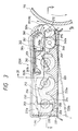
- the developing unit 210 has a case 230, toner T accommodated in the case 230, a developing roller 211 for supplying toner T to the surface of the photosensitive member 110, a supply roller 240 for supplying toner T to the developing roller 211, three conveying fins 251, 252 and 253 for conveying toner T toward the supply roller 240 and a restraining blade 260 pressed against the developing roller 211 so that the quantity of toner is restrained.
- the developing unit 210 has a sealing member 270 ( Fig. 5(a) ) for preventing leakage of toner between the shafts of the developing roller, the supply roller, the conveying fins, and the case.
- the case 230 has a case body 231 and a cover 222.
- Toner is typically prepared in such a manner that pigment, CCA (Charge Control Agent) and wax are bound with synthetic resin. Moreover, an additive having a relatively large diameter for mainly realizing durability and another additive having a relatively small diameter for realizing fluidity are added to the surface realized by the binding process.
- CCA Charge Control Agent
- the toner components and characteristic of the components were determined as follows.
- the synthetic resin is polyester to improve the fixing characteristic.
- the particle size of toner is not less than 6 ⁇ m nor more than 9 ⁇ m .
- the particle size is 6 ⁇ m or smaller, the cleaning characteristic deteriorates and the cost cannot be reduced. If the particle size is 9 ⁇ m or larger, the resolution deteriorates. In this embodiment, the particle size is 7 ⁇ m.
- the particle size of the pigment may be 30 nm to 50 nm. In this embodiment, pigment having particle size of about 50 nm is employed.
- the quantity of the pigment is made to be not less than 5 wt% nor more than 15 wt%. The reason for this is that the capacity of the hopper must be reduced while the density of the formed image is maintained so as to reduce the size of the developing unit 210. If the pigment quantity exceeds 15 wt%, the supply characteristic deteriorates because the electrification characteristic deteriorates to the point where filming of the developing roller and filming of the blade easily take place.
- the quantity of the CCA is made not less than 0.5 wt% nor more than 3 wt%. To improve the electrification .characteristic, the quantity of CCA must be 0.5 wt% or more. If the quantity of CCA exceeds 3 wt%, the transfer characteristic deteriorates.
- the quantity of the wax is 0.5 wt% or larger. This improves the separation characteristic of toner from the fixing roller. Moreover, the fixing strength of toner to a recording medium, such as paper, is strengthened.
- An additive having a large diameter is silicon oil having a particle size of about 40 nm which is larger than 1/2 of the particle size of the pigment.
- the quantity of the additive is not less than 0.5 wt% nor more than 5 wt%.
- the additive having the large diameter must be 0.5 wt% or more. However, if the quantity of the additive having the large diameter exceeds 5 wt%, the supply characteristic deteriorates because the fluidity deteriorates.
- the size of the additive having the large diameter to toner is larger than 1/2 of the diameter of the pigment, therefore even if a large quantity of the pigment exists on the surfaces of the matrices of toner particles, the additive having the large diameter projects over the pigment surfaces of the matrices of the particles so that they do not come in contact with the electrified members. Since the additive having the large diameter is usually an inorganic material having a high hardness, filming of the same to the electrified members does not easily take place from mechanical contact or friction. Therefore, filming of the pigment of toner to the electrified members is prevented.
- the ratio of the additive having the large diameter covering matrices of particles is not lower than 10%. Specifically, the quantity of the additive having the large diameter is contained by 0.5 wt% or larger. As a result, the ratio of the additive having the large diameter covering the surfaces of the matrices of the toner particles can be made to be 10% or more.
- the ratio of the additive covering the surfaces of the matrices of the particles is 10% or higher, the additive is able to substantially fully cover the pigment even if a large quantity of the pigment exists on the surfaces of the matrices of the toner particles. Thus, filming of the pigment of toner to the electrified members is prevented.
- an additive having a small diameter is used to improve the fluidity of toner.
- the additive having the small diameter is hexamethdisilanzane (HMDS) having a particle size of about 14 nm.
- HMDS hexamethdisilanzane
- the quantity is not less than 1.0 wt% nor more than 3 wt%. The reason for this lies in that 1.0 wt% or more is required for the small diameter additive (in terms of the projected area of the additive) to cover 100% or more the surface, that is, to cover substantially all the surfaces of the toner particles.
- the covering ratio of the additive is again obtained from the above equation.
- the ratio of additive having the small diameter covering the matrices of toner accommodated in the case is 100% or higher. Therefore, even if a large quantity of the pigment exists on the surfaces of the matrices of toner, the additive covers the pigment. Therefore, the pigment existing on the surfaces of the matrices of toner does not directly come in contact with or slide on the electrified members, such as the developing roller and the restraining blade. As a result, the electrified members are free from filming. Because the additive having a small diameter is usually made of an inorganic material having a high hardness, filming of the additive to the electrified member does not take place during mechanical contact and sliding. Thus, filming of the pigment of toner to the electrified members is prevented.
- the developing roller 211 is structured in such a manner that the surface of the developing roller 211 for conveying toner is shorter than the restraining blade 260. Moreover, the developing roller 211 has a shaft 212 which is rotatably supported by side walls 231a of the case body 231 through bearings 232. A gear 213 for rotating the developing roller 211 is secured to an end of the shaft 212. A transmission gear 214 for transmitting drive torque supplied from a torque source (not shown) is engaged with the gear 213. A roller 215 is rotatably disposed at the two ends of the shaft 212.
- the roller 215 is brought into contact with flanges (not shown) formed at the two ends of the photosensitive member 110 when the developing roller 211 is brought into contact with the photosensitive member 110 to restrain the position of the developing roller 211 with respect to the photosensitive member 110.
- the restraining blade 260 is longer than the surface of the developing roller 211 for conveying toner.
- the restraining blade 260 is secured to a leading end 261a of a support plate 261.
- the support plate 261 has a bent rear end 261b supported by three hook portions 262b (see Fig. 4 ) of a base plate 262 secured to the case body 231.
- the support plate 261 is able to swing relative to the support portion.
- the support plate 261 is urged in such a manner that the support plate 261 presses the developing roller 211 of the restraining blade 260 by at least two (three in the structure shown in the drawing) tension springs 263 disposed between an intermediate portion 261c of the support plate 261 and a front portion 262a of the base plate 262.
- the shaft 212 of the developing roller 211 is rotatably supported by the side walls 231a of the case body 231 in such a manner that at least an end of the shaft 212 penetrates the side walls 231a. Therefore, a sealing member 270 for preventing leakage of toner is provided.
- the sealing member 270 is formed into a laminate obtained by sticking a foam member 271 in the form of a sheet to a napped material 272.
- the foam member 271 mainly attains the sealing pressure, while the napped material 272 mainly attains a sealing characteristic.
- toner on the overall surface of the developing roller for conveying toner is uniformly restrained by the restraining blade. Therefore, any defect of the toner seal which is caused from toner excessively conveyed from the surface of the developing roller, or free toner which appears attributable to toner conveyed excessively, is prevented. Moreover, toner is uniformly formed over the surface of the developing roller and therefore serves as a lubricant between the photosensitive member and the developing roller. As a result, damage of the photosensitive member is reduced.
- the developing unit according to the present invention has the seals disposed at the ends of the developing roller, introduction of toner from the surface of the developing roller into the side end of the developing roller is prevented. Therefore, the sealing portion of the developing roller does not damage the photosensitive member as has been experienced with the conventional structure and excellent sealing of toner is achieved.
- the developing unit of the present invention is formed such that the quantity of elastic deformation of the sealing member is larger than the difference between the length of the restraining blade and the length of the surface of the developing roller for conveying toner.
- the quantity of elastic deformation of the napped material 272 of the sealing member 270 is made larger than the difference between the length of the surface of the developing roller 211 and the length of the restraining blade.
- the length of the fur of the napped material 272 is made to be 2 mm because the foregoing difference is 0.2 mm.
- the sealing member 270 arranged as described above is disposed at an end of the developing roller. Therefore, the sealing member flexibly follows a stepped portion generated by the difference in the length between the developing roller and the restraining blade thereby preventing leakage of toner from the stepped portion and thus the characteristic for sealing toner is further improved.
- the developing roller 211 is structured in such a manner that the end portions of the developing roller are chamfered so as to be rounded.
- the radius is made to be 0.2 mm.
- the quantity of elastic displacement of the sealing member is larger than the quantity of chamfering of the developing roller 211.
- the quantity of elastic displacement of furs of the napped material 272 of the sealing member 270 is made to be larger than the quantity of chamfering of the end portion of the developing roller 211. Since the radius of chamfering is 0.2 mm in this embodiment, the length of the furs of the napped material 272 is 2 mm which is included in the quantity of elastic displacement.
- the end portion of the surface of the developing roller for conveying toner is chamfered, the end portion of the developing roller is not brought into contact with the photosensitive member. Thus, damage of the photosensitive member which occurs due to contact and sliding of the edge of the end portion of the developing roller is prevented. Since the quantity of the elastic displacement of the sealing member is larger than the quantity of chamfering of the end portion of the developing roller, the sealing member is able to flexibly follow the chamfered portion at the end of the developing roller. Therefore, the photosensitive member is not damaged by the end of the developing roller as has been experienced with the conventional structure.
- the developing unit according to this embodiment has a sealed end portion of the developing roller introduction of toner from the surface of the developing roller for conveying toner into the side end portion of the same is prevented.
- the supply roller 240 has a shaft 241 rotatably supported by side walls 231a of the case body 231 through the bearings 242 (one bearing is shown in Fig. 5 (a) ).
- a gear 243 for rotating the supply roller 240 is secured to an end of the shaft 241.
- a transmission gear (not shown) for transmitting the force supplied from a torque source (not shown) is engaged to the gear 243.
- the restraining blade 260 is secured to a leading end 261a of a support plate 261.
- the support plate 261 has a bent rear end 261b supported by three hook portions 262b (see Fig. 4 ) of a base plate 262 secured to the case body 231.
- the support plate 261 is able to swing relative to the support portion.
- the support plate 261 is urged in such a manner that the support plate 261 presses the developing roller 211 of the restraining blade 260 by at least two (three in the structure shown in the drawing) tension springs 263 disposed between an intermediate portion 261c of the support plate 261 and a front portion 262a of the base plate 262.
- the conveying fins 251, 252 and 253 basically have the same structure as one another and have, similar to the above-mentioned supply roller 240, a shaft 254 rotatably supported by the side walls 231a of the case body 231. Moreover, each fin has an arm 255 secured to the shaft 254 and a fin 256 secured to the leading end of the arm 255 and formed into a thin plate (a sheet plate) having flexibility. Moreover, the fin has a gear or a ratchet secured to the shaft 254 at a position outside the case body 231. Thus, the fins 251, 252 and 253 can be rotated in the direction indicated by the associated 1 arrow shown in Fig. 3 by a torque source (not shown). Note that the number of revolutions of the conveying fins 251, 252 and 253 is determined to be about 1/20 to about 1/50 the numbering revolutions of the supply roller 240.
- the case body 231 accommodates a toner reserving portion 233 formed into a cylindrical shape.
- a wedge-shape space 233b is formed in which toner T is held and conveyed. That is, toner T is supplied through a route as conveying fin 253 - 252 - 251 - supply roller 240, and then to the developing roller 211.
- the conveying fins are structured in such a manner that the number of revolutions of the conveying fins is not less than 1/50 of number of revolution of the supply roller nor more than 1/20 of the same, excessive conveyance of toner to the supply roller portion by the conveying fins is further prevented.
- toner conveyed by the conveying fins exceeds that which is consumed by the developing roller and the supply roller.
- toner is brought to a compressed state.
- toner is moved before the excess portion of conveyed toner is returned to the conveying fins.
- the state of compression becomes more critical.
- the quantity of toner which is conveyed by the conveying fins is insufficient to compensate the quantity of toner which is consumed from the developing roller and the supply roller.
- the developing unit of the present invention is able to prevent the compression of toner caused by the conveying member and also prevent the defects in conveyance experienced with the conventional structure.
- the present invention includes a plurality of conveying fins disposed in a horizontal direction and the number of revolutions of the conveying fin nearest the supply roller is larger than the number of revolutions of each of the other conveying fins.
- the rotations of the conveying fins 252 and 253 are slower than the rotation of the conveying fin 251 to prevent excessive conveyance of toner in a short time.
- the number of revolutions of the conveying fin 251 is not less than 1/50 nor more than 1/20 of the number of revolution of the supply roller.
- the structure of the present invention conveys toner in the case to the supply roller portion more slowly as described above, compression of toner in the supply roller portion is prevented. Because the conveying fin nearest the supply roller undergoes the above-mentioned number of revolutions, insufficient conveyance of toner is prevented, and also compression of toner caused by the conveying fins is prevented.
- the conveying fins 251, 252, and 253 have different phases of rotation from one another so that the rotational loads are uniformed.
- the angles among the conveying fins of the n conveying devices are shifted by 360°/n.
- the lengths for which the fin 256 is slidably brought into contact with the wall surface 233a is made to be substantially constant regardless of the angles of the conveying fins 251, 252 and 253.
- change in the load occurring before and after toner is elastically discharged by the conveying fins is dispersed. Even if dense toner having poor fluidity is used, the load of the conveying fins can be uniformed thereby preventing change in the torque required by the apparatus.
- the foregoing developing unit 210 represents four developing units 210Y for yellow images, 210C for cyan images, 210M for magenta images and 210K for black images, which are detachably attached to the frame 220.
- reference numeral 222 represents a receiving plate of each of the developing units 210 (Y, C, M and K).
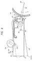
- the receiving plate 222 has a pair of side plates (not shown) formed integrally therewith. As shown in Fig. 6 , the receiving plate 222 is slidably joined to the frame 220 by a shaft 223 projecting over the outer surface of the side plate.
- a tension spring 224 is disposed between the side plate and the frame 220. The tension spring 224 urges the receiving plate 222 in a clockwise direction when viewed in Fig. 6 , that is, in a direction in which the receiving plate 222 presses the developing roller 211 of the developing unit 210 against the photosensitive member 110.
- At least one of the side plates is provided with a pin 225 for a cam in such a manner that the pin 225 for the cam is in contact with a cam 226 provided to the frame 220.
- the cam 226 is rotated by a drive device (not shown).
- the cam 226 is placed at a position indicated with a solid line shown in Fig. 6
- the developing roller 211 is pressed against the photosensitive member 110 due to the urging force of the tension spring 224.
- the cam 226 swings the receiving plate 222 and the developing unit 210 counterclockwise in such a manner that the developing roller 211 is separated from the photosensitive member 110.
- the above-mentioned cam structure is provided for all of the receiving plates 222 (Y, C, M and K). Therefore, control of the rotation of the cam enables only any one of the developing rollers 211 to be brought into contact with the photosensitive member 110.
- the shaft 223 and pin 225 for the cam may be provided for the case body 231 of the developing unit 210.
- reference numeral 180 represents a sub-frame of the photosensitive unit 100.
- the sub-frame 180 accommodates the charging roller 120 and the cleaning device 130.
- the cleaning device 130 has a fur brush 131 for wiping toner left on the outer surface of the photosensitive member 110 off and a cleaner blade 132 for furthermore scraping toner left and allowed to adhere to the outer surface of the photosensitive member 110 off.
- the cleaning device 130 has a toner conveying screw 133 serving as a conveying device for conveying toner wiped or scraped off by the fur brush 131 or the cleaner blade 132.
- a toner recovery chamber 182 is formed in the lower portion of the sub-frame 180. The toner recovery chamber 182 accommodates the fur brush 131, the cleaner blade 132 and the toner conveying screw 133.
- the fur brush 131 is secured to a shaft 131a which penetrates the side plate of the sub-frame 180.
- a drive device not shown
- the fur brush 131 is rotated in a direction indicated by the associated arrow shown in Fig. 2 .
- the cleaner blade 132 is joined to the sub-frame 180 by dint of a joint plate 132a.
- the leading end (the lower end) of the cleaner blade 132 is brought into contact with the outer surface of the photosensitive member 110 in such a manner as to scrape toner off.
- the toner conveying screw 133 is rotated in a direction indicated by the associated arrow shown in Fig. 2 by a drive device (not shown) to convey toner accommodated in the toner recovery chamber 182 to a waste toner box (not shown) as waste toner.
- the center of rotation of the conveying fin is disposed lower than the center of rotation of the supply roller in order to efficiently create a space for accommodating toner.
- the thickness of the developing unit has been reduced.
- the foregoing developing unit having the conveying fin disposed lower than the supply roller encounters difficulty in that the convey fin scrapes toner up to the surface of the toner supply roller even if the quantity of toner in the case has become insufficient.
- Such a defect in conveyance of toner undesirably causes the density of a formed image to deteriorate.
- angle ⁇ is measured to have positive values in the clockwise direction from the horizontal line H.
- the angle ⁇ is not more than - 20°, toner cannot smoothly be conveyed from the conveying fin 251 to the supply roller 240. If the angle ⁇ is 75° or larger, excess toner is conveyed to the supply roller 240 which leads to excessively compressed toner.
- the state of excessive compression is a phenomenon that the space formed by the developing roller 211, the supply roller 240 and the restraining blade 260 is filled with toner and thus the pressure in the space is raised excessively. If the excessive compression state is realized, toner on the developing roller cannot be limited to an appropriate quantity by the restraining blade, and toner overflows the restraining portion.
- the angle ⁇ satisfies the above-mentioned range, toner is appropriately supplied to the supply roller 240 and is also appropriately supplied to the developing roller 211. Therefore, the plural developing units 210 can be disposed around the single photosensitive member 110. As a result, images can quickly be formed in such a manner that idle time can be shortened.
- the diameter of the photosensitive member 110 is determined to be in a range from 80 mm to 90 mm. And it is preferable that the range of ⁇ satisfies - 12° ⁇ ⁇ ⁇ 56°.
- Toner in the case body 231 is conveyed in such a manner that toner is held in the wedge-shape space 233b formed when the rotating fin 256 is slidably brought into contact with the wall surface 233a of the toner reserving portion 233. Since the fin 256 has a thin flexible plate-like shape (the sheet-like shape) the fin is rapidly displaced and released at a portion near the supply roller. Specifically, when the fin 256 is separated from the wall surface 233a of the toner reserving portion 233, toner held in the wedge-shape space 233b and conveyed as described above is elastically discharged by dint of the restoring force generated by the elasticity of the fin 256. To achieve this elastic discharge, the quantity of displacement between the fin 256 and the wall surface 233a is made large. The discharging force depends upon the rigidity (the elasticity) of the fin 256.
- an apparent density of toner is made to be not less than 0.3 g/cc nor more than 0.5 g/cc.
- the conveyance characteristic depends on the fluidity of toner.
- the quantity of the additive having the small diameter which affects the fluidity of toner was employed as a parameter for use in experiments.
- A.D is made to be 0.3 g/cc when the quantity of the additive is 1.0% or larger which gives a satisfactory conveyance characteristic. If the quantity exceeds 3.0%, the A.D undesirably exceeds 0.5 g/cc which leads to an excessive conveyance characteristic that causes toner to be leaked due to compression thereof. Therefore, it is preferable that the A.D of toner is not less than 0.30 g/cc nor more than 0.5 g/cc.
- the developing roller 211 is made of SUS or AL having a diameter of 15 mm to 25 mm (more preferably about 18 mm).
- the surface of the developing roller 211 is subjected to a blasting process or a chemical polishing process to have appropriate roughness for holding toner.
- the structure is arranged in such a manner that rotation center 02 of the developing roller 211 is located more adjacent to the direction in which the force F1 acts than line S2 which connects swing center 03 (the portion including the shaft 223) of the developing unit 210 and rotation center O1 of the photosensitive member 110 to each other.
- the developing roller 211 is arranged to be moved in the direction in which the force F1 acts on the developing unit 210.
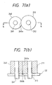
- the supply roller 240 is made of the porous and elastic material, the portion 240a of the supply roller 240 in which the supply roller 240 is in contact with the developing roller 211 is dented, as shown in Fig. 3 .
- the foregoing state is schematically shown in Figs. 7 (a) and 7 (b) .
- the projection is given reference numeral 240b. If the projection 240b engages the sealing member.SE, the torque required to rotate the supply roller 240 is enlarged unsatisfactorily. Therefore, this embodiment has a chamfered corner portion 244 of the supply roller 240, as shown in Fig. 5 (a) . Note that chamfering may be formed by a straight line as shown in Fig. 5 (a) or may be rounded. As a result of the structure of the present invention, the above-mentioned undesirable engagement is prevented, thus, torque required to rotate the supply roller 240 is reduced.
- a gap C is formed in the engaged portion at a position between the sealing member SE and the end surface of the developing roller 211, as shown in Fig. 7 (b) , which leads to toner being introduced into the gap C. If toner is introduced into gap C, then the sealing characteristic deteriorates and the end portion of the developing roller 211 is contaminated by toner.
- the structure of the present invention is able to prevent the above-mentioned problems.
- the shaft 212 of the developing roller 211, the shaft 241 of the supply roller 240 and each shaft 254 of the conveying fins 251, 252 and 253 are rotatably supported by the side walls 231a of the case body 231. At least the end of each axis penetrates the side walls 231a. Therefore, a sealing member is provided for the penetrating portion to prevent leakage of toner.
- this embodiment has a structure that a sealing member 270 is formed into a laminate obtained by sticking a foam member 271 in the form of a sheet and a napped material 272.
- the foam member 271 mainly attains the sealing pressure, while the napped material 272 mainly attains a sealing characteristic.
- the napped material 272 has napped members 273 which are formed into a discontinuous swirl shape attributable to rotations of the roller. That is, a so-called labyrinth seal is formed. Therefore, leakage of toner is reliably prevented. Moreover, the napped members 273 are formed into shapes following the rotation of the roller which reduces torque required to rotate the roller. Note that a sealing member 270 is provided for each of the shafts of the conveying fins 251, 252 and 253 though it is omitted from illustration in Fig. 5 (a) . Referring to Fig. 5 (a) , reference numeral 274 represents a sheet-shape lubricating material made of a fluorine material having low friction.
- the present invention includes reference surfaces 213a and 214a for the gear 213 and the transmission gear 214, respectively, to stabilize the engagement between the gear 213 and the transmission gear 214.
- the (developing unit 210K' for black images) is different from the first embodiment.
- the other portions are the same.
- the developing unit 210K' for forming black images has somewhat large size to accommodate toner in a larger quantity.
- two conveying fins 251' and 253' are provided.
- the consumption of black toner is expected to be the largest among four colors of toner. Therefore, it is preferable that the developing unit 210K' has a large size as is employed in this embodiment.
- the following description is made about more specific structures of toner, the developing roller 211, the supply roller 240 and the restraining blade 260.
- the developing characteristics are classified into a conveying characteristic, a supply characteristic, a filming phenomenon experienced with the developing roller, a filming phenomenon experienced with the restraining blade, a development efficiency, a sealing characteristic, fogging, durability, hysteresis phenomenon, irregularity of images and the difference in the density between the leading end and the trailing end.
- the influences of the above-mentioned structures on the characteristics and phenomena will be described.
- the capacity of the hopper and the preservability considered to be important factors for the developing unit will be considered. Then, the arrangement of the structure will be described.
- the basic structure of toner according to this embodiment is arranged in such a manner that pigment, CCA (Charge Control Agent) and wax are bound with synthetic resin. Moreover, an additive having a relatively large diameter for mainly realizing durability and another additive having a relatively small diameter for realizing fluidity are added to the surface realized by the binding process.
- CCA Charge Control Agent
- the conveying characteristic considerably depends on the fluidity of toner.
- the quantity of the additive having the small diameter and affecting the fluidity of toner is made to be 1.0% or larger, a satisfactory conveying characteristic can be obtained. If the quantity exceeds 3.0%, the conveying characteristic is raised excessively.
- the supply characteristic is a characteristic for conveying toner from the supply roller 240 to the developing roller 211. If the supply characteristic is unsatisfactory, image wanting takes place at the cycles of the supply roller 240.
- the supply characteristic is determined by the characteristic of toner and the structures of the supply roller 240 and the developing roller 211.
- the quantity of the additive having the small diameter is 1.0 wt% or larger, the characteristic for supplying toner is improved.
- the quantity of the pigment is 15 wt% or smaller and that of the CCA is 3 wt% or smaller, the charging operation is able to satisfactorily start up and thus the supply characteristic can be improved.
- the depth of engagement (the depth of a dent of the supply roller 240) between the supply roller 240 and the developing roller 211 is 0.1 mm or larger, toner can sufficiently be rubbed on the developing roller 211.
- the frictional electrification is improved and the supply characteristic can be improved.
- the mechanical conveying force can be enlarged and thus a satisfactory supply characteristic is realized.
- the supply characteristic can be improved by any one of the above-mentioned characteristics, combination of the characteristics will furthermore improve the supply characteristic.
- the quantity of development (the quantity of toner developed on the photosensitive member 110) is 0.80 mg/cm 2 or smaller, that the quantity of conveyance (the quantity of toner on the developing roller 211 which is subjected to the development process) is 0.60 mg/cm 2 and the quantity of electrification is - 8 ⁇ C/g or smaller.
- the filming phenomenon of the developing roller depends on the supply characteristic of toner. If the toner supply characteristic is unsatisfactory, a portion is formed on the developing roller 211 in which the quantity of toner is too small. Thus, toner in the portion is stressed excessively by the restraining blade 260, and the developing roller 211, which causes the filming phenomenon to occur on the developing roller.
- the quantity of the CCA is made to be 3 wt% or smaller, the quantity of the pigment is 15 wt% or smaller and the quantity of the additive having the small diameter is made to be 1.5 wt% or greater.
- the quantity of the CCA is made to be 3 wt% or smaller, the quantity of the pigment is 15 wt% or smaller and the quantity of the additive having the small diameter is made to be 1.5 wt% or greater.
- the foregoing phenomenon is determined by the toner supply characteristic and a state of a portion in which the restraining blade 260 is brought into contact with the developing roller 211.
- toner supply characteristic is unsatisfactory, a portion is formed on the developing roller 211 in which the quantity of toner is too small. Thus, toner in the portion is stressed excessively by the restraining blade 260, and the developing roller 211, which causes the filming phenomenon to occur on the restraining blade.
- size of the space formed by the contact portion between the developing roller 211 and the restraining blade 260 can be set to a size which permits toner on the developing roller 211 restrained by the restraining blade 260 to be returned to the supply roller 240. If the size of the space is too small, toner excessively fills in this space which causes the filming phenomenon to occur.
- This efficiency is indicated by a ratio of a portion of toner actually used in the process for developing the photosensitive member 110 with respect to the overall quantity of toner brought to the developing position by the developing roller 211.
- the sealing characteristic is a manner of leakage of toner from toner seals (a seal for the lower surface is given reference numeral 275 in Fig. 3 ) provided for the end surfaces and the lower surface of the developing roller 211. Leakage of toner occurring in the image region causes a defective image. If leakage occurs on the outside of the image region, contamination of the inside portion of the apparatus takes place.
- the toner seal 275 is allowed to abut against the developing roller.
- "Abutting against the developing roller” means a state except that in which the sealing member in the form of the film is allowed to abut against only the opened end which is not secured to the developing unit. That is, the foregoing state includes a state in which portions except for the end portion of the film are brought into contact with the developing roller and a state in which portions including the end portions are brought into contact with the same.
- the sealing member is displaced because of the contact with the developing roller. It is preferable that the sealing member be brought into contact with the developing roller in such a manner that the quantity ⁇ of displacement satisfies 0.1 mm ⁇ ⁇ ⁇ 0.8 mm.
- the fogging phenomenon is one in which toner adheres to a non-image portion (which is usually a white portion). If an inverse development process using negatively-charged toner is performed, the potential of the photosensitive member is about -50 V in the image portion and the same is about - 600 V in the non-image portion. Moreover, the development bias is made to be about - 300 V. Therefore, negatively-charged toner does not usually adhere to the non-image portion. If positively-charged toner exists on the developing roller, toner of this type undesirably adheres to the non-image portion. If toner having a small quantity of electrification exists, the force for attracting toner to the developing roller by electrostatic force and the like to constrain toner to the developing roller is unsatisfactory. Therefore, toner undesirably adheres to the photosensitive member.
- the electrification polarities are made to be the same and the quantity of electrification of toner is enlarged (a small quantity in the case of negatively-charged toner) so that the fogging phenomenon is reduced.
- the quantity of conveyance is reduced and the opportunity of contact between the electrification supply members (the restraining blade and the developing roller) and toner is increased to cause friction electrification to satisfactorily take place.
- the quantity of conveyance be 0.60 mg/cm 2 or smaller and the quantity of electrification be - 8 ⁇ C/g or smaller.
- the supply roller have the same potential as that of the developing roller.
- the durability is a degree of deterioration in an image which takes place when images are superimposed.
- the deterioration in the image takes place due to deterioration of toner, filming of toner and wear of the restraining blade 260 or the like.
- the supply characteristic and transfer characteristic of toner deteriorate when the additive having the small diameter is embedded in the resin.
- the quantity of the additive having the small diameter in toner is 1.5 wt% or greater and the quantity of the additive having the large diameter is 0.5 wt% or greater to prevent the additive having the small diameter from being embedded.
- the additive having the large diameter is silicon oil having a particle size of about 40 nm.
- the quantity of CCA is 3 wt% or smaller and the quantity of the pigment is 15 wt% or smaller.
- This phenomenon is a phenomenon that a pattern of an image, which has been first formed, affects an image which is formed later.
- the hysteresis phenomenon occurs when start-up of the electrification of toner is unsatisfactory.
- the start-up of the electrification is determined by the quantities of the CCA and the additive in toner. If the quantity of the CCA is 0.5 wt% or larger, the start-up of the electrification is improved. If the coating ratio of the additive is low, the effect of the CCA can easily be obtained because the matrix particle containing the kneaded CCA can easily be brought into contact with the electrification supply member.
- the quantity of the additive having the large diameter is not less than 1.5 wt% nor more than 5 wt% and the quantity of the additive having the small diameter is not less than 1.5 wt% nor more than 3 wt%.
- the additive having the large diameter is a material processed with silicon oil, while the additive having the small diameter is a material processed with HMDS (hexamethdisilanzane). It is preferable that the particle size of the additive having the large diameter is about 40 nm and that of the additive having the small diameter is about 14 nm.
- the difference in the quantity of electrification of toner between the leading end and the trailing end is 15 ⁇ c/g or smaller.
- This phenomenon is one in which images are formed irregularly in a case where regular images are attempted to be formed.
- the occurrence of this phenomenon depends upon the rotation cycles of the rotating members, i.e., the developing roller and the supply roller. If excessive deflection of the rotating member occurs, image irregularity easily takes place. Therefore, it is preferable that the deflection occurring from the center of rotation of the developing roller be 30 ⁇ m or smaller and that occurring from the center of rotation of the supply roller be 150 ⁇ m or smaller.
- the roughness of the base of a pipe for forming the developing roller realized before the roughness of the surface is adjusted exceeds 1 ⁇ m in Rmax, the roughness of the surface cannot easily be uniformed by a following process. In this case, irregularity of formed images easily takes place. Therefore, it is preferable that roughness of the base of the foregoing pipe is 1 ⁇ m or smaller in Rmax.
- the material of a shaft serving as the center of rotation of the developing roller is too weak, the quantity of deflection which occurs by external force when the developing roller is rotated is excessively enlarged. Therefore, it is preferable that the material of the shaft be iron.
- This phenomenon is one in which the density (the quantity of development) is different between the leading end of an image and the trailing end of the same when a solid-color image has been formed. This phenomenon occurs because the quantity of electrification and that of conveyance of toner on the developing roller are different between the portions corresponding to the leading end and the portions corresponding to the trailing end and, therefore, the quantity of development is different.
- the foregoing phenomenon can be prevented by making the difference in the conveyance of toner between the leading end and the trailing end to be 0.15 mg/cm 2 or smaller and by making the difference in the quantity of electrification 15 ⁇ C/g or smaller. Moreover, the phenomenon can be prevented by making the difference in the quantity of development 0.15 ⁇ g/cm 2 or smaller.
- the restraining blade must be brought into contact with the surface at an edge thereof.
- the quantity of conveyance is enlarged excessively.
- the angle of contact must not be less than 50° nor more than 85°. It is preferable that the quantity of the CCA in toner is 0.5 wt% or greater.
- Preservability indicates a manner of deterioration of the above-mentioned characteristics in a state (of, for example, an environment of transportation or an environment of reservation) in which the apparatus is not operated.
- the deterioration of the foregoing type takes place due to the so-called a blocking phenomenon in which toner is solidified in the developing unit.
- Tg of toner is made to be 55°C or higher, the blocking phenomenon is prevented.
- the developing characteristics are as described above. In consideration of the above-mentioned factors, the specific structures of toner, the developing roller 211, the supply roller 240 and the restraining blade 260 are determined as described hereinafter.
- toner is prepared in such a manner that the pigment, the CCA (the Charge Control Agent) and the wax are bound with the synthetic resin. Moreover, the additive having the relatively large diameter for mainly realizing durability and the additive having the relatively small diameter for realizing fluidity are added to the surface realized by the binding process.
- the synthetic resin was polyester to improve the fixing characteristic.
- the quantity of the pigment was made to be not less than 5 wt% nor more than 15 wt%., so that the capacity of the hopper is reduced while the density of the formed image is maintained so as to reduce the size of the developing unit 210.
- the quantity of the pigment is 5 wt% or smaller, the saturation of a color image deteriorates. If the quantity exceeds 15 wt%, the supply characteristic deteriorates to the point where filming of the developing roller and filming of the blade easily take place.
- the quantity of the wax was 0.5 wt% or larger.
- the reason for this is that the separation characteristic of toner from the fixing roller must be improved. Moreover, such strengthens the fixing strength of toner to a recording medium, such as paper.
- the additive having the small diameter was HMDS having a particle size of about 14 nm.
- the quantity was not less than 1.0 wt% nor more than 3 wt%. The reason for this is that the fixing characteristic deteriorates if the quantity exceeds 3 wt%. It is preferable that the quantity is 1.5 wt% or larger to improve the transfer characteristic.
- the particle size of toner was not less than 6 ⁇ m nor more than 9 ⁇ m. The reason for this is that the cleaning characteristic deteriorates and the cost cannot be reduced if the particle size is 6 ⁇ m or smaller. If the particle size exceeds 9 ⁇ m, the resolution deteriorates.
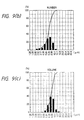
- Figs. 9 (a) , 9 (b) and 9 (c) Distribution of particle sizes of toner employed in this embodiment is shown in Figs. 9 (a) , 9 (b) and 9 (c) .
- the distribution of the particle size of toner was measured using a coal tar counter model "TA-II".
- the aperture diameter was 100 ⁇ m and electrolyte was ISOTON-II.
- the coating ratio a quantity with which 100%, that is, substantially the entire surface of the toner particle was covered with the additive (in terms of the projected area) was added.
- Tg was made to be 55° or higher. The reason for this is as described above.
- Tm was made to be not lower than 110°C nor higher than 130°C. The reason for this is as described above. If the toner is 130°C or higher, the fixing characteristic deteriorates.
- the distribution of molecular weight (MW/MN) was made to be 100 or greater. If the distribution is 100 or smaller, the fixing characteristic deteriorates.
- the quantity of development was not less than 0.40 mg/cm 2 nor more than 0.8 mg/cm 2 .
- the difference between the leading end and the trailing end was 0.15 mg/cm 2 .
- the reason for this is as described above. If the quantity is 0.40 mg/cm 2 or smaller, the density of the image is lowered. If the quantity is 0.80 mg/cm 2 or larger, the transfer characteristic deteriorates.
- the quantity of conveyance was made not less than 0.35 mg/cm 2 nor more than 0.60 mg/cm 2 .
- the difference between the leading end and the trailing end was made to be 0.15 mg/cm 2 . The reason for this is as described above.
- the quantity of electrification was made not less than - 35 ⁇ C/g nor more than - 8 ⁇ C/g.
- the reason why the quantity was made to be - 8 ⁇ C/g or smaller is as described above. If the quantity is - 35 ⁇ C/g, the transfer characteristic deteriorates.
- the shape factor SF-1 indicates the degree of roundness of toner
- shape factor SF-2 indicates the degree of projections and depressions of toner. It is preferable that the shape factor SF-1 of toner is 100 to 150, more preferably 100 to 130. It is preferable that the shape factor SF-2 of toner is 100 to 140, more preferably 100 to 125. Since the shape factors SF-1 and SF-2 are determined as described above, the transfer efficiency in the primary and secondary transfer operations is improved.
- the developing unit is structured so that the ratio of open cells of the supply roller is 30% or higher, the depth of engagement of the supply roller to the developing roller is 0.4 mm or smaller, the shape factor SF-1 of toner is 150 or smaller and the shape factor SF-2 is 140 or smaller.
- the shape factor SF-1 of toner is 150 or smaller, that is, since toner has a spherical shape, a substantial volume of toner in the cell can be reduced even if the cells are enclosed with toner. As a result, clogging of the supply roller with toner in a short time is prevented. Therefore, an expanded material having a low ratio of open cells as compared with that of the conventional expanded material is employed. Since the shape factor SF-2 of toner is 140 or smaller, that is, since the surface projections and depressions are reduced and smoothed, toner introduced into the cells can easily be discharged from the cells even if the cells are filled with toner. Even if toner is coagulated in the cells attributable to pressure, toner can easily be crushed. Even if coagulated toner is discharged from the cells, the restraining blade is not clogged with the toner, because toner of the foregoing type can easily be crushed, therefore no defects take place in the formed images.
- the hardness of the supply roller is not increased over time, as has been experienced with the conventional structure.
- torque required to rotate the supply roller is reduced.
- the ratio is 50% or lower, the toner supply characteristic to the developing roller cannot be maintained. If the ratio is 80% or higher, toner deteriorates and also the drive torque is enlarged excessively.
Landscapes
- Physics & Mathematics (AREA)
- General Physics & Mathematics (AREA)
- Dry Development In Electrophotography (AREA)
Claims (3)
- Entwicklungseinheit, die Folgendes umfasst:ein Gehäuse (230);Toner, der in dem Gehäuse untergebracht ist, wobei der Toner eine Teilchengröße aufweist, die weder weniger als 6 µm und mehr als 9 µm beträgt;eine Entwicklungswalze (211), die drehbar von dem Gehäuse durch eine erste Welle (212) gehaltert ist; undeine Zufuhrwalze (240), die drehbar von dem Gehäuse durch eine zweite Welle (241) gehaltert ist, wobei die Zufuhrwalze durch ein elastisches Element gebildet wird, das so angeordnet ist, dass es in einer solchen Weise gegen die Entwicklungswalze gepresst wird, dass der Toner auf die Oberfläche der Entwicklungswalze aufgebracht wird, wobei:das elastische Element aus einem geschäumten Material besteht, das ein Offenzellenverhältnis von 30% oder mehr aufweist;eine Eingriffnahmetiefe der Zufuhrwalze mit Bezug auf die Entwicklungswalze 0,4 mm oder weniger beträgt; undder Toner einen Formfaktor SF-1 von 150 oder weniger und einen Formfaktor SF-2 von 140 oder weniger aufweist.
- Entwicklungseinheit gemäß Anspruch 1, wobei die Zufuhrwalze Eckabschnitte (244) aufweist, die angeschrägt sind.
- Entwicklungsverfahren, das folgende Schritte umfasst:Unterbringen von Toner in einem Gehäuse (230), wobei der Toner eine Teilchengröße aufweist, die 6 µm oder mehr und 9 µm oder weniger beträgt, und einen Formfaktor SF-1 von 150 oder weniger und einen Formfaktor SF-2 von 140 oder weniger aufweist;Bereitstellen einer Entwicklungswalze (211), die drehbar von dem Gehäuse durch eine erste Welle (212) gehaltert ist;Bereitstellen einer Zufuhrwalze (240), die drehbar von dem Gehäuse durch eine zweite Welle (241) gehaltert ist und durch ein elastisches Element gebildet wird, das aus einem geschäumten Material besteht, das ein Offenzellenverhältnis von 30% oder mehr aufweist;Anordnen der Entwicklerwalze und der Zufuhrwalze in einer solchen Weise, dass eine Eingriffnahmetiefe der Zufuhrwalze mit Bezug auf die Entwicklungswalze 0,4 mm oder mehr beträgt; undAufbringen des Toners auf die Oberfläche der Entwicklerwalze aus dem Gehäuse mittels der Zufuhrwalze.
Applications Claiming Priority (23)
| Application Number | Priority Date | Filing Date | Title |
|---|---|---|---|
| JP3267897 | 1997-01-31 | ||
| JP3267897A JP3510074B2 (ja) | 1997-01-31 | 1997-01-31 | 現像器 |
| JP4646097A JPH10239982A (ja) | 1997-02-28 | 1997-02-28 | 現像器 |
| JP9046473A JPH10239971A (ja) | 1997-02-28 | 1997-02-28 | 現像器 |
| JP4647197 | 1997-02-28 | ||
| JP9046469A JPH10240009A (ja) | 1997-02-28 | 1997-02-28 | 現像器 |
| JP4647197A JPH10239895A (ja) | 1997-02-28 | 1997-02-28 | 現像器 |
| JP4645997 | 1997-02-28 | ||
| JP4645997A JPH10240000A (ja) | 1997-02-28 | 1997-02-28 | 現像器 |
| JP4645897A JPH10239987A (ja) | 1997-02-28 | 1997-02-28 | 現像器 |
| JP4646797A JPH10239997A (ja) | 1997-02-28 | 1997-02-28 | 現像器 |
| JP4646997 | 1997-02-28 | ||
| JP4646897 | 1997-02-28 | ||
| JP4647297A JP3558107B2 (ja) | 1997-02-28 | 1997-02-28 | 現像器 |
| JP9046468A JPH10240006A (ja) | 1997-02-28 | 1997-02-28 | 現像器 |
| JP4647297 | 1997-02-28 | ||
| JP4647097 | 1997-02-28 | ||
| JP4647397 | 1997-02-28 | ||
| JP4646797 | 1997-02-28 | ||
| JP4647097A JPH10239894A (ja) | 1997-02-28 | 1997-02-28 | 現像器 |
| JP4645897 | 1997-02-28 | ||
| JP4646097 | 1997-02-28 | ||
| EP98300703A EP0856781B1 (de) | 1997-01-31 | 1998-01-30 | Entwicklungseinheit |
Related Parent Applications (1)
| Application Number | Title | Priority Date | Filing Date |
|---|---|---|---|
| EP98300703A Division EP0856781B1 (de) | 1997-01-31 | 1998-01-30 | Entwicklungseinheit |
Publications (3)
| Publication Number | Publication Date |
|---|---|
| EP1324151A2 EP1324151A2 (de) | 2003-07-02 |
| EP1324151A3 EP1324151A3 (de) | 2004-12-08 |
| EP1324151B1 true EP1324151B1 (de) | 2008-02-20 |
Family
ID=27581938
Family Applications (3)
| Application Number | Title | Priority Date | Filing Date |
|---|---|---|---|
| EP98300703A Expired - Lifetime EP0856781B1 (de) | 1997-01-31 | 1998-01-30 | Entwicklungseinheit |
| EP03075921A Withdrawn EP1324150A3 (de) | 1997-01-31 | 1998-01-30 | Enwicklungseinheit |
| EP03075922A Expired - Lifetime EP1324151B1 (de) | 1997-01-31 | 1998-01-30 | Entwicklungseinheit |
Family Applications Before (2)
| Application Number | Title | Priority Date | Filing Date |
|---|---|---|---|
| EP98300703A Expired - Lifetime EP0856781B1 (de) | 1997-01-31 | 1998-01-30 | Entwicklungseinheit |
| EP03075921A Withdrawn EP1324150A3 (de) | 1997-01-31 | 1998-01-30 | Enwicklungseinheit |
Country Status (3)
| Country | Link |
|---|---|
| US (8) | US6163674A (de) |
| EP (3) | EP0856781B1 (de) |
| DE (1) | DE69825505T8 (de) |
Families Citing this family (35)
| Publication number | Priority date | Publication date | Assignee | Title |
|---|---|---|---|---|
| JP4365969B2 (ja) * | 2000-01-20 | 2009-11-18 | キヤノン株式会社 | 現像装置、プロセスカートリッジ及び電子写真画像形成装置 |
| JP2001255741A (ja) * | 2000-03-09 | 2001-09-21 | Canon Inc | 仕切り部材及びシール部品及び現像装置及びプロセスカートリッジ |
| JP4666753B2 (ja) * | 2000-12-12 | 2011-04-06 | キヤノン株式会社 | 現像剤収納容器及び現像装置及びプロセスカートリッジ及び画像形成装置 |
| US6795675B2 (en) * | 2001-02-26 | 2004-09-21 | Canon Kabushiki Kaisha | Developing-carrying member, and developing apparatus and image forming apparatus including the member |
| JP2002296904A (ja) * | 2001-03-29 | 2002-10-09 | Brother Ind Ltd | 現像装置 |
| JP2003107967A (ja) * | 2001-09-28 | 2003-04-11 | Ricoh Co Ltd | 電源制御装置及び画像形成装置 |
| JP2003233287A (ja) * | 2001-12-07 | 2003-08-22 | Ricoh Co Ltd | 画像形成装置及び画像形成方法 |
| ATE370445T1 (de) * | 2001-12-07 | 2007-09-15 | Seiko Epson Corp | Entwicklungsgerät und dieses beinhaltender bildformungsapparat |
| JP3918593B2 (ja) * | 2002-03-12 | 2007-05-23 | ブラザー工業株式会社 | 現像装置および画像形成装置 |
| KR100509499B1 (ko) * | 2002-06-15 | 2005-08-22 | 삼성전자주식회사 | 칼라화상형성장치 및 그를 이용한 칼라화상형성방법 |
| JP2004226524A (ja) * | 2003-01-21 | 2004-08-12 | Ricoh Co Ltd | トナー移送装置及びトナー補給装置並びに画像形成装置 |
| US20040184046A1 (en) * | 2003-03-17 | 2004-09-23 | Toshiba Tec Kabushiki Kaisha | Image forming apparatus and image forming method |
| US7251440B2 (en) * | 2003-04-28 | 2007-07-31 | Konica Minolta Business Technologies, Inc. | Development apparatus and image formation apparatus |
| US7005458B2 (en) * | 2003-06-20 | 2006-02-28 | Foamex L.P. | Static dissipative polyurethane foams |
| US6813470B1 (en) | 2003-07-10 | 2004-11-02 | Lexmark International, Inc. | High density foam roll |
| KR100561471B1 (ko) | 2003-10-20 | 2006-03-16 | 삼성전자주식회사 | 전자사진방식 화상형성장치의 토너 카트리지 |
| JP4027302B2 (ja) * | 2003-11-11 | 2007-12-26 | 株式会社沖データ | 画像形成装置 |
| JP4337095B2 (ja) * | 2004-03-22 | 2009-09-30 | セイコーエプソン株式会社 | トナー及びそのトナーを用いた現像装置 |
| TWI252031B (en) * | 2004-05-18 | 2006-03-21 | Avision Inc | Duplex scan method capable of quickly detecting a document size |
| JP4738838B2 (ja) * | 2005-02-24 | 2011-08-03 | 株式会社リコー | 画像形成装置 |
| JP2006267805A (ja) * | 2005-03-25 | 2006-10-05 | Brother Ind Ltd | 現像装置および画像形成装置 |
| JP4862317B2 (ja) * | 2005-08-10 | 2012-01-25 | ブラザー工業株式会社 | 画像形成装置、及び、この画像形成装置で用いられる現像ユニット |
| KR100741467B1 (ko) * | 2006-07-12 | 2007-07-20 | 삼성전자주식회사 | 반도체 장치 및 그 제조방법 |
| JP4841000B2 (ja) * | 2006-12-11 | 2011-12-21 | キヤノン株式会社 | 現像剤容器、現像装置、及びプロセスカートリッジ |
| US7720426B2 (en) * | 2007-01-29 | 2010-05-18 | Kabushiki Kaisha Toshiba | Cleaning device and image forming apparatus using the same |
| JP2008203310A (ja) * | 2007-02-16 | 2008-09-04 | Konica Minolta Business Technologies Inc | カラー画像形成装置、及びそれに装着されるプロセスカートリッジ |
| US8032064B2 (en) * | 2007-10-26 | 2011-10-04 | Seiko Epson Corporation | Developer apparatus, image forming apparatus and developing method |
| JP4492670B2 (ja) * | 2007-10-26 | 2010-06-30 | セイコーエプソン株式会社 | 現像装置、画像形成装置および現像方法 |
| JP4483928B2 (ja) * | 2007-10-26 | 2010-06-16 | セイコーエプソン株式会社 | 現像装置、画像形成装置および現像方法 |
| JP4783836B2 (ja) * | 2009-02-17 | 2011-09-28 | シャープ株式会社 | 画像形成装置 |
| JP5794159B2 (ja) | 2012-01-25 | 2015-10-14 | ブラザー工業株式会社 | 画像形成装置 |
| JP6066639B2 (ja) * | 2012-09-13 | 2017-01-25 | キヤノン株式会社 | 現像装置及びプロセスカートリッジ |
| JP6112298B2 (ja) * | 2013-03-01 | 2017-04-12 | 株式会社リコー | 現像装置、プロセスユニット及び画像形成装置 |
| DE202013008357U1 (de) * | 2013-09-13 | 2013-11-18 | Ball Europe Gmbh | Behälterdose und Halteeinrichtung |
| JP6575146B2 (ja) * | 2015-05-29 | 2019-09-18 | 富士ゼロックス株式会社 | 画像形成装置及び画像形成方法 |
Family Cites Families (66)
| Publication number | Priority date | Publication date | Assignee | Title |
|---|---|---|---|---|
| US3999514A (en) | 1975-09-29 | 1976-12-28 | International Business Machines Corporation | Magnetic brush developer |
| US4345013A (en) * | 1977-02-28 | 1982-08-17 | Black Copy Company, Inc. | Dual purpose magnetic toner |
| JPS5830583B2 (ja) * | 1977-11-24 | 1983-06-30 | キヤノン株式会社 | 静電像の液体現像装置 |
| US4592653A (en) * | 1982-03-12 | 1986-06-03 | Ricoh Company, Ltd. | Dry process developing apparatus |
| GB2163371B (en) | 1984-08-07 | 1988-04-07 | Ricoh Kk | Developing electrostatic latent images |
| JPH0646331B2 (ja) * | 1985-03-27 | 1994-06-15 | 株式会社東芝 | 現像装置の製造方法 |
| US4788570A (en) * | 1985-04-15 | 1988-11-29 | Ricoh Company, Ltd. | Thin film developing device |
| JPS62244054A (ja) * | 1986-04-16 | 1987-10-24 | Fuji Photo Film Co Ltd | 加圧画像形成装置 |
| JPS63208877A (ja) * | 1987-02-26 | 1988-08-30 | Canon Inc | 接触帯電装置 |
| JPH07113787B2 (ja) | 1987-03-31 | 1995-12-06 | キヤノン株式会社 | 静電荷像現像用現像剤の製造方法 |
| JPS63244055A (ja) * | 1987-03-31 | 1988-10-11 | Canon Inc | 静電荷像現像用トナ−の製造方法 |
| US4987452A (en) * | 1987-12-29 | 1991-01-22 | Minolta Camera Kabushiki Kaisha | Developing apparatus provided with a chamber for controlling toner grain diameter |
| JPH01277868A (ja) * | 1988-04-30 | 1989-11-08 | Toshiba Corp | 現像装置 |
| JPH0237378A (ja) * | 1988-07-27 | 1990-02-07 | Toshiba Corp | 現像装置 |
| JPH0254289A (ja) | 1988-08-18 | 1990-02-23 | Canon Inc | 画像形成装置 |
| JPH0734665B2 (ja) | 1989-05-19 | 1995-04-12 | 三菱電機株式会社 | 誘導電動機の駆動装置 |
| JP2646393B2 (ja) * | 1989-05-31 | 1997-08-27 | キヤノン株式会社 | 現像装置 |
| JPH03235974A (ja) | 1990-02-13 | 1991-10-21 | Ricoh Co Ltd | 電子写真装置の現像器 |
| JP3001611B2 (ja) | 1990-05-31 | 2000-01-24 | 株式会社東芝 | 現像装置 |
| JPH0470762A (ja) * | 1990-07-11 | 1992-03-05 | Ricoh Co Ltd | 静電荷像現像用トナー |
| JP2843660B2 (ja) * | 1990-08-30 | 1999-01-06 | キヤノン株式会社 | 現像装置 |
| US5172168A (en) * | 1990-09-05 | 1992-12-15 | Matsushita Electric Industrial Co., Ltd. | Electrophotographic system haivng a developing device with a plurality of toner feeders |
| US5286917A (en) * | 1990-09-28 | 1994-02-15 | Canon Kabushiki Kaisha | Apparatus for developing electrostatic latent image and developing roller therefor |
| JPH04328582A (ja) * | 1991-04-30 | 1992-11-17 | Fujitsu Ltd | 非磁性一成分カラートナー現像方法 |
| JPH04355461A (ja) * | 1991-05-31 | 1992-12-09 | Mita Ind Co Ltd | 電子写真用二成分系トナー |
| US5294968A (en) | 1991-07-09 | 1994-03-15 | Konica Corporation | Developing unit and drive transmission attachment |
| JP2602376B2 (ja) | 1991-07-17 | 1997-04-23 | 三田工業株式会社 | 電子写真用ブラックトナー |
| US5151739A (en) | 1991-07-29 | 1992-09-29 | Eastman Kodak Company | Development apparatus and improved auger device for use therein |
| US5287150A (en) | 1991-09-06 | 1994-02-15 | Canon Kabushiki Kaisha | Developing device including rotatable resilient roller for supplying developer to and removing developer from a developer bearing member |
| JPH05134527A (ja) | 1991-11-08 | 1993-05-28 | Mita Ind Co Ltd | 現像装置 |
| JPH05142938A (ja) | 1991-11-26 | 1993-06-11 | Ricoh Co Ltd | 電子写真記録装置 |
| US5585895A (en) | 1991-12-19 | 1996-12-17 | Canon Kabushiki Kaisha | Developing device and process cartridge with it |
| JP3197934B2 (ja) * | 1992-03-24 | 2001-08-13 | キヤノン株式会社 | 現像装置 |
| JP3103704B2 (ja) | 1992-06-02 | 2000-10-30 | セイコーエプソン株式会社 | 現像装置 |
| JPH05341636A (ja) | 1992-06-10 | 1993-12-24 | Ricoh Co Ltd | 電子写真装置の現像器 |
| JPH0627807A (ja) * | 1992-07-09 | 1994-02-04 | Hiraoka H I Kenkyusho:Kk | 現像装置 |
| JPH06167887A (ja) | 1992-11-30 | 1994-06-14 | Fuji Xerox Co Ltd | 画像形成装置 |
| JP2985594B2 (ja) | 1992-12-03 | 1999-12-06 | セイコーエプソン株式会社 | 画像形成方法 |
| JPH0736273A (ja) * | 1992-12-30 | 1995-02-07 | Ricoh Co Ltd | 現像装置 |
| JPH0713390A (ja) | 1993-04-19 | 1995-01-17 | Canon Inc | シール部材及び前記シール部材を用いたプロセスカートリッジ及び画像形成装置 |
| JP3343406B2 (ja) * | 1993-07-23 | 2002-11-11 | 株式会社リコー | 現像装置 |
| GB2283702B (en) | 1993-10-13 | 1997-04-09 | Seiko Epson Corp | Contact transfer device and image forming equipment |
| JP3093918B2 (ja) * | 1993-11-25 | 2000-10-03 | キヤノン株式会社 | 現像装置 |
| JP3066943B2 (ja) | 1993-11-29 | 2000-07-17 | キヤノン株式会社 | 画像形成方法 |
| JPH07271178A (ja) * | 1994-04-01 | 1995-10-20 | Ricoh Co Ltd | 現像剤供給ローラ |
| JP2938753B2 (ja) | 1994-05-10 | 1999-08-25 | 東芝テック株式会社 | 電子写真装置の現像装置 |
| US5659859A (en) * | 1994-06-21 | 1997-08-19 | Mita Industrial Co., Ltd. | Developer agitating/conveying device |
| US5592268A (en) * | 1994-07-22 | 1997-01-07 | Brother Kogyo Kabushiki Kaisha | Mechanism to prevent toner leakage from an image forming unit |
| JPH0862958A (ja) | 1994-08-19 | 1996-03-08 | Nec Corp | トナー供給機構 |
| JPH0882999A (ja) | 1994-09-09 | 1996-03-26 | Ricoh Co Ltd | 現像装置 |
| JPH0882998A (ja) | 1994-09-09 | 1996-03-26 | Ricoh Co Ltd | 現像装置 |
| JP3282704B2 (ja) * | 1994-10-06 | 2002-05-20 | キヤノン株式会社 | 現像装置 |
| IL111441A (en) | 1994-10-28 | 2004-06-01 | Hewlett Packard Indigo Bv | Squeegee roller for imaging systems |
| KR0171165B1 (ko) | 1994-10-31 | 1999-03-30 | 미따라이 후지오 | 화상 형성 방법, 화상 형성 장치 및 프로세스 카트리지 |
| DE69520328T2 (de) * | 1994-11-08 | 2001-08-23 | Canon K.K., Tokio/Tokyo | Toner für die Entwicklung elektrostatischer Bilder, Zwei-Komponenten-Entwickler, Entwicklungsmethode, Bilderzeugungsverfahren, Hitzefixierverfahren und Verfahren zur Herstellung von Tonern |
| EP0713158B1 (de) | 1994-11-17 | 2000-03-01 | Canon Kabushiki Kaisha | Bilderzeugungsgerät |
| JPH08146625A (ja) * | 1994-11-24 | 1996-06-07 | Oki Data:Kk | 感光体ロ−ラと有機光半導体塗布方法と電子写真記録装置 |
| EP0716350B1 (de) | 1994-12-05 | 2001-04-11 | Canon Kabushiki Kaisha | Toner für die Entwicklung elektrostatischer Bilder |
| JP3501428B2 (ja) | 1994-12-16 | 2004-03-02 | 株式会社リコー | トナー搬送ローラおよび画像形成装置 |
| JP3397510B2 (ja) * | 1994-12-21 | 2003-04-14 | キヤノン株式会社 | 現像装置及びプロセスカートリッジ |
| US5637427A (en) | 1995-03-07 | 1997-06-10 | Fuji Xerox Co., Ltd. | Full color toner for electrostatic charge development, method for producing the toner, and image forming method using the toner |
| EP1338929A3 (de) * | 1995-04-20 | 2004-12-01 | Ricoh Company, Ltd. | Entwicklungsvorrichtung für Zweikomponentenentwickler |
| JPH08328374A (ja) | 1995-06-02 | 1996-12-13 | Canon Inc | 画像形成装置用現像ローラ及びその製造方法 |
| JPH09138557A (ja) | 1995-11-10 | 1997-05-27 | Mita Ind Co Ltd | 静電潜像現像装置 |
| US5758230A (en) * | 1995-11-10 | 1998-05-26 | Mita Industrial Co., Ltd. | Device for developing electrostatic latent image |
| JP3235974B2 (ja) | 1997-05-26 | 2001-12-04 | ニッシンコーポレーション株式会社 | フッ素樹脂ライニングfrp缶体とその製造方法 |
-
1998
- 1998-01-30 EP EP98300703A patent/EP0856781B1/de not_active Expired - Lifetime
- 1998-01-30 EP EP03075921A patent/EP1324150A3/de not_active Withdrawn
- 1998-01-30 DE DE69825505T patent/DE69825505T8/de not_active Expired - Fee Related
- 1998-01-30 EP EP03075922A patent/EP1324151B1/de not_active Expired - Lifetime
-
1999
- 1999-08-09 US US09/369,937 patent/US6163674A/en not_active Expired - Fee Related
- 1999-08-09 US US09/369,936 patent/US6295433B1/en not_active Expired - Fee Related
- 1999-08-09 US US09/369,855 patent/US6198893B1/en not_active Expired - Fee Related
- 1999-08-09 US US09/370,151 patent/US6192209B1/en not_active Expired - Fee Related
- 1999-08-09 US US09/369,938 patent/US6226484B1/en not_active Expired - Fee Related
- 1999-08-09 US US09/369,939 patent/US6094554A/en not_active Expired - Fee Related
- 1999-08-09 US US09/369,935 patent/US6151474A/en not_active Expired - Fee Related
-
2001
- 2001-01-05 US US09/754,340 patent/US6336022B2/en not_active Expired - Fee Related
Also Published As
| Publication number | Publication date |
|---|---|
| DE69825505T2 (de) | 2005-01-20 |
| US6295433B1 (en) | 2001-09-25 |
| EP0856781A2 (de) | 1998-08-05 |
| EP1324151A2 (de) | 2003-07-02 |
| EP0856781A3 (de) | 2000-05-24 |
| EP1324150A3 (de) | 2004-12-08 |
| US6163674A (en) | 2000-12-19 |
| DE69825505D1 (de) | 2004-09-16 |
| US20010005461A1 (en) | 2001-06-28 |
| EP1324151A3 (de) | 2004-12-08 |
| EP0856781B1 (de) | 2004-08-11 |
| US6094554A (en) | 2000-07-25 |
| EP1324150A2 (de) | 2003-07-02 |
| US6198893B1 (en) | 2001-03-06 |
| DE69825505T8 (de) | 2005-05-04 |
| US6151474A (en) | 2000-11-21 |
| US6336022B2 (en) | 2002-01-01 |
| US6192209B1 (en) | 2001-02-20 |
| US6226484B1 (en) | 2001-05-01 |
Similar Documents
| Publication | Publication Date | Title |
|---|---|---|
| EP1324151B1 (de) | Entwicklungseinheit | |
| US7450870B2 (en) | Developing device using one-component toner for an image forming apparatus, and a process cartridge including the developing device | |
| EP1162514B1 (de) | Verfahren und Gerät zur Bildentwicklung, welches zur Bildung einer gleichmässigen Entwicklerschicht geeignet ist | |
| US7221892B2 (en) | Developing device used in image forming device | |
| US7706714B2 (en) | Image-forming device and developer cartridge having leakage restraining member and developer moving member | |
| US5621505A (en) | Developing apparatus having rotatable developer supply member for developer carrying member | |
| JPH10239982A (ja) | 現像器 | |
| EP1380903B1 (de) | Entwicklungseinrichtung und electrophotografisches Gerät | |
| JP4081367B2 (ja) | 現像装置 | |
| JP3510074B2 (ja) | 現像器 | |
| JP4617199B2 (ja) | 現像装置及び画像形成装置 | |
| US7072607B2 (en) | Developing apparatus | |
| JP3985774B2 (ja) | 現像器 | |
| JP3558107B2 (ja) | 現像器 | |
| JPH10240009A (ja) | 現像器 | |
| JPH10239894A (ja) | 現像器 | |
| DE69839162T2 (de) | Entwicklungseinheit | |
| JPH10239997A (ja) | 現像器 | |
| JPH10239895A (ja) | 現像器 | |
| JPH10239971A (ja) | 現像器 | |
| JPH10240006A (ja) | 現像器 | |
| JPH10239987A (ja) | 現像器 | |
| JPH10240000A (ja) | 現像器 | |
| JP2017146470A (ja) | 画像形成装置 | |
| US7068961B2 (en) | Developing device, image forming apparatus, image forming system, sealing member, and method for manufacturing sealing member |
Legal Events
| Date | Code | Title | Description |
|---|---|---|---|
| PUAI | Public reference made under article 153(3) epc to a published international application that has entered the european phase |
Free format text: ORIGINAL CODE: 0009012 |
|
| 17P | Request for examination filed |
Effective date: 20030422 |
|
| AC | Divisional application: reference to earlier application |
Ref document number: 0856781 Country of ref document: EP Kind code of ref document: P |
|
| AK | Designated contracting states |
Designated state(s): DE FR GB |
|
| PUAL | Search report despatched |
Free format text: ORIGINAL CODE: 0009013 |
|
| AK | Designated contracting states |
Kind code of ref document: A3 Designated state(s): DE FR GB |
|
| 17Q | First examination report despatched |
Effective date: 20050218 |
|
| TPAC | Observations by third parties |
Free format text: ORIGINAL CODE: EPIDOSNTIPA |
|
| TPAB | Information related to observations by third parties deleted |
Free format text: ORIGINAL CODE: EPIDOSDTIPA |
|
| TPAC | Observations by third parties |
Free format text: ORIGINAL CODE: EPIDOSNTIPA |
|
| AKX | Designation fees paid |
Designated state(s): DE FR GB |
|
| GRAP | Despatch of communication of intention to grant a patent |
Free format text: ORIGINAL CODE: EPIDOSNIGR1 |
|
| GRAS | Grant fee paid |
Free format text: ORIGINAL CODE: EPIDOSNIGR3 |
|
| GRAA | (expected) grant |
Free format text: ORIGINAL CODE: 0009210 |
|
| AC | Divisional application: reference to earlier application |
Ref document number: 0856781 Country of ref document: EP Kind code of ref document: P |
|
| AK | Designated contracting states |
Kind code of ref document: B1 Designated state(s): DE FR GB |
|
| REG | Reference to a national code |
Ref country code: GB Ref legal event code: FG4D |
|
| REF | Corresponds to: |
Ref document number: 69839162 Country of ref document: DE Date of ref document: 20080403 Kind code of ref document: P |
|
| ET | Fr: translation filed | ||
| PLBE | No opposition filed within time limit |
Free format text: ORIGINAL CODE: 0009261 |
|
| STAA | Information on the status of an ep patent application or granted ep patent |
Free format text: STATUS: NO OPPOSITION FILED WITHIN TIME LIMIT |
|
| 26N | No opposition filed |
Effective date: 20081121 |
|
| PGFP | Annual fee paid to national office [announced via postgrant information from national office to epo] |
Ref country code: DE Payment date: 20090123 Year of fee payment: 12 |
|
| PGFP | Annual fee paid to national office [announced via postgrant information from national office to epo] |
Ref country code: GB Payment date: 20090128 Year of fee payment: 12 |
|
| PGFP | Annual fee paid to national office [announced via postgrant information from national office to epo] |
Ref country code: FR Payment date: 20090113 Year of fee payment: 12 |
|
| GBPC | Gb: european patent ceased through non-payment of renewal fee |
Effective date: 20100130 |
|
| REG | Reference to a national code |
Ref country code: FR Ref legal event code: ST Effective date: 20100930 |
|
| PG25 | Lapsed in a contracting state [announced via postgrant information from national office to epo] |
Ref country code: FR Free format text: LAPSE BECAUSE OF NON-PAYMENT OF DUE FEES Effective date: 20100201 |
|
| PG25 | Lapsed in a contracting state [announced via postgrant information from national office to epo] |
Ref country code: DE Free format text: LAPSE BECAUSE OF NON-PAYMENT OF DUE FEES Effective date: 20100803 |
|
| PG25 | Lapsed in a contracting state [announced via postgrant information from national office to epo] |
Ref country code: GB Free format text: LAPSE BECAUSE OF NON-PAYMENT OF DUE FEES Effective date: 20100130 |