EP1294578B2 - Verfahren, vorrichtung und system zum herstellen von bauteilen mit vorbestimmtem oberflächenaussehen, insbesondere von frontplatten von küchenelementen - Google Patents
Verfahren, vorrichtung und system zum herstellen von bauteilen mit vorbestimmtem oberflächenaussehen, insbesondere von frontplatten von küchenelementen Download PDFInfo
- Publication number
- EP1294578B2 EP1294578B2 EP01956502.7A EP01956502A EP1294578B2 EP 1294578 B2 EP1294578 B2 EP 1294578B2 EP 01956502 A EP01956502 A EP 01956502A EP 1294578 B2 EP1294578 B2 EP 1294578B2
- Authority
- EP
- European Patent Office
- Prior art keywords
- printed
- components
- front panel
- front panels
- wood
- Prior art date
- Legal status (The legal status is an assumption and is not a legal conclusion. Google has not performed a legal analysis and makes no representation as to the accuracy of the status listed.)
- Expired - Lifetime
Links
Images


Classifications
-
- B—PERFORMING OPERATIONS; TRANSPORTING
- B41—PRINTING; LINING MACHINES; TYPEWRITERS; STAMPS
- B41J—TYPEWRITERS; SELECTIVE PRINTING MECHANISMS, i.e. MECHANISMS PRINTING OTHERWISE THAN FROM A FORME; CORRECTION OF TYPOGRAPHICAL ERRORS
- B41J2/00—Typewriters or selective printing mechanisms characterised by the printing or marking process for which they are designed
- B41J2/005—Typewriters or selective printing mechanisms characterised by the printing or marking process for which they are designed characterised by bringing liquid or particles selectively into contact with a printing material
- B41J2/01—Ink jet
- B41J2/17—Ink jet characterised by ink handling
- B41J2/18—Ink recirculation systems
-
- B—PERFORMING OPERATIONS; TRANSPORTING
- B05—SPRAYING OR ATOMISING IN GENERAL; APPLYING FLUENT MATERIALS TO SURFACES, IN GENERAL
- B05B—SPRAYING APPARATUS; ATOMISING APPARATUS; NOZZLES
- B05B12/00—Arrangements for controlling delivery; Arrangements for controlling the spray area
- B05B12/08—Arrangements for controlling delivery; Arrangements for controlling the spray area responsive to condition of liquid or other fluent material to be discharged, of ambient medium or of target ; responsive to condition of spray devices or of supply means, e.g. pipes, pumps or their drive means
- B05B12/12—Arrangements for controlling delivery; Arrangements for controlling the spray area responsive to condition of liquid or other fluent material to be discharged, of ambient medium or of target ; responsive to condition of spray devices or of supply means, e.g. pipes, pumps or their drive means responsive to conditions of ambient medium or target, e.g. humidity, temperature position or movement of the target relative to the spray apparatus
- B05B12/122—Arrangements for controlling delivery; Arrangements for controlling the spray area responsive to condition of liquid or other fluent material to be discharged, of ambient medium or of target ; responsive to condition of spray devices or of supply means, e.g. pipes, pumps or their drive means responsive to conditions of ambient medium or target, e.g. humidity, temperature position or movement of the target relative to the spray apparatus responsive to presence or shape of target
-
- B—PERFORMING OPERATIONS; TRANSPORTING
- B05—SPRAYING OR ATOMISING IN GENERAL; APPLYING FLUENT MATERIALS TO SURFACES, IN GENERAL
- B05B—SPRAYING APPARATUS; ATOMISING APPARATUS; NOZZLES
- B05B13/00—Machines or plants for applying liquids or other fluent materials to surfaces of objects or other work by spraying, not covered by groups B05B1/00 - B05B11/00
- B05B13/02—Means for supporting work; Arrangement or mounting of spray heads; Adaptation or arrangement of means for feeding work
- B05B13/04—Means for supporting work; Arrangement or mounting of spray heads; Adaptation or arrangement of means for feeding work the spray heads being moved during spraying operation
- B05B13/0447—Installation or apparatus for applying liquid or other fluent material to conveyed separate articles
-
- B—PERFORMING OPERATIONS; TRANSPORTING
- B05—SPRAYING OR ATOMISING IN GENERAL; APPLYING FLUENT MATERIALS TO SURFACES, IN GENERAL
- B05B—SPRAYING APPARATUS; ATOMISING APPARATUS; NOZZLES
- B05B13/00—Machines or plants for applying liquids or other fluent materials to surfaces of objects or other work by spraying, not covered by groups B05B1/00 - B05B11/00
- B05B13/02—Means for supporting work; Arrangement or mounting of spray heads; Adaptation or arrangement of means for feeding work
- B05B13/04—Means for supporting work; Arrangement or mounting of spray heads; Adaptation or arrangement of means for feeding work the spray heads being moved during spraying operation
- B05B13/0463—Installation or apparatus for applying liquid or other fluent material to moving work of indefinite length
- B05B13/0468—Installation or apparatus for applying liquid or other fluent material to moving work of indefinite length with reciprocating or oscillating spray heads
-
- B—PERFORMING OPERATIONS; TRANSPORTING
- B05—SPRAYING OR ATOMISING IN GENERAL; APPLYING FLUENT MATERIALS TO SURFACES, IN GENERAL
- B05B—SPRAYING APPARATUS; ATOMISING APPARATUS; NOZZLES
- B05B13/00—Machines or plants for applying liquids or other fluent materials to surfaces of objects or other work by spraying, not covered by groups B05B1/00 - B05B11/00
- B05B13/02—Means for supporting work; Arrangement or mounting of spray heads; Adaptation or arrangement of means for feeding work
- B05B13/04—Means for supporting work; Arrangement or mounting of spray heads; Adaptation or arrangement of means for feeding work the spray heads being moved during spraying operation
- B05B13/0463—Installation or apparatus for applying liquid or other fluent material to moving work of indefinite length
- B05B13/0468—Installation or apparatus for applying liquid or other fluent material to moving work of indefinite length with reciprocating or oscillating spray heads
- B05B13/0473—Installation or apparatus for applying liquid or other fluent material to moving work of indefinite length with reciprocating or oscillating spray heads with spray heads reciprocating along a straight line
-
- B—PERFORMING OPERATIONS; TRANSPORTING
- B05—SPRAYING OR ATOMISING IN GENERAL; APPLYING FLUENT MATERIALS TO SURFACES, IN GENERAL
- B05B—SPRAYING APPARATUS; ATOMISING APPARATUS; NOZZLES
- B05B13/00—Machines or plants for applying liquids or other fluent materials to surfaces of objects or other work by spraying, not covered by groups B05B1/00 - B05B11/00
- B05B13/02—Means for supporting work; Arrangement or mounting of spray heads; Adaptation or arrangement of means for feeding work
- B05B13/04—Means for supporting work; Arrangement or mounting of spray heads; Adaptation or arrangement of means for feeding work the spray heads being moved during spraying operation
- B05B13/0463—Installation or apparatus for applying liquid or other fluent material to moving work of indefinite length
- B05B13/0468—Installation or apparatus for applying liquid or other fluent material to moving work of indefinite length with reciprocating or oscillating spray heads
- B05B13/0473—Installation or apparatus for applying liquid or other fluent material to moving work of indefinite length with reciprocating or oscillating spray heads with spray heads reciprocating along a straight line
- B05B13/0478—Installation or apparatus for applying liquid or other fluent material to moving work of indefinite length with reciprocating or oscillating spray heads with spray heads reciprocating along a straight line the angular position of the spray heads relative to the straight line being modified during the reciprocating movement
-
- B—PERFORMING OPERATIONS; TRANSPORTING
- B27—WORKING OR PRESERVING WOOD OR SIMILAR MATERIAL; NAILING OR STAPLING MACHINES IN GENERAL
- B27D—WORKING VENEER OR PLYWOOD
- B27D1/00—Joining wood veneer with any material; Forming articles thereby; Preparatory processing of surfaces to be joined, e.g. scoring
- B27D1/04—Joining wood veneer with any material; Forming articles thereby; Preparatory processing of surfaces to be joined, e.g. scoring to produce plywood or articles made therefrom; Plywood sheets
-
- B—PERFORMING OPERATIONS; TRANSPORTING
- B41—PRINTING; LINING MACHINES; TYPEWRITERS; STAMPS
- B41J—TYPEWRITERS; SELECTIVE PRINTING MECHANISMS, i.e. MECHANISMS PRINTING OTHERWISE THAN FROM A FORME; CORRECTION OF TYPOGRAPHICAL ERRORS
- B41J3/00—Typewriters or selective printing or marking mechanisms characterised by the purpose for which they are constructed
- B41J3/407—Typewriters or selective printing or marking mechanisms characterised by the purpose for which they are constructed for marking on special material
- B41J3/4073—Printing on three-dimensional objects not being in sheet or web form, e.g. spherical or cubic objects
-
- B—PERFORMING OPERATIONS; TRANSPORTING
- B44—DECORATIVE ARTS
- B44C—PRODUCING DECORATIVE EFFECTS; MOSAICS; TARSIA WORK; PAPERHANGING
- B44C5/00—Processes for producing special ornamental bodies
- B44C5/04—Ornamental plaques, e.g. decorative panels, decorative veneers
-
- B—PERFORMING OPERATIONS; TRANSPORTING
- B44—DECORATIVE ARTS
- B44C—PRODUCING DECORATIVE EFFECTS; MOSAICS; TARSIA WORK; PAPERHANGING
- B44C5/00—Processes for producing special ornamental bodies
- B44C5/04—Ornamental plaques, e.g. decorative panels, decorative veneers
- B44C5/043—Ornamental plaques, e.g. decorative panels, decorative veneers containing wooden elements
-
- B—PERFORMING OPERATIONS; TRANSPORTING
- B41—PRINTING; LINING MACHINES; TYPEWRITERS; STAMPS
- B41J—TYPEWRITERS; SELECTIVE PRINTING MECHANISMS, i.e. MECHANISMS PRINTING OTHERWISE THAN FROM A FORME; CORRECTION OF TYPOGRAPHICAL ERRORS
- B41J2203/00—Embodiments of or processes related to the control of the printing process
- B41J2203/01—Inspecting a printed medium or a medium to be printed using a sensing device
- B41J2203/011—Inspecting the shape or condition, e.g. wrinkled or warped, of a medium to be printed before printing on it
-
- B—PERFORMING OPERATIONS; TRANSPORTING
- B41—PRINTING; LINING MACHINES; TYPEWRITERS; STAMPS
- B41M—PRINTING, DUPLICATING, MARKING, OR COPYING PROCESSES; COLOUR PRINTING
- B41M5/00—Duplicating or marking methods; Sheet materials for use therein
- B41M5/0011—Pre-treatment or treatment during printing of the recording material, e.g. heating, irradiating
-
- B—PERFORMING OPERATIONS; TRANSPORTING
- B41—PRINTING; LINING MACHINES; TYPEWRITERS; STAMPS
- B41M—PRINTING, DUPLICATING, MARKING, OR COPYING PROCESSES; COLOUR PRINTING
- B41M5/00—Duplicating or marking methods; Sheet materials for use therein
- B41M5/0041—Digital printing on surfaces other than ordinary paper
- B41M5/0047—Digital printing on surfaces other than ordinary paper by ink-jet printing
-
- B—PERFORMING OPERATIONS; TRANSPORTING
- B41—PRINTING; LINING MACHINES; TYPEWRITERS; STAMPS
- B41M—PRINTING, DUPLICATING, MARKING, OR COPYING PROCESSES; COLOUR PRINTING
- B41M5/00—Duplicating or marking methods; Sheet materials for use therein
- B41M5/0041—Digital printing on surfaces other than ordinary paper
- B41M5/0076—Digital printing on surfaces other than ordinary paper on wooden surfaces, leather, linoleum, skin, or flowers
-
- B—PERFORMING OPERATIONS; TRANSPORTING
- B41—PRINTING; LINING MACHINES; TYPEWRITERS; STAMPS
- B41M—PRINTING, DUPLICATING, MARKING, OR COPYING PROCESSES; COLOUR PRINTING
- B41M7/00—After-treatment of prints, e.g. heating, irradiating, setting of the ink, protection of the printed stock
- B41M7/0027—After-treatment of prints, e.g. heating, irradiating, setting of the ink, protection of the printed stock using protective coatings or layers by lamination or by fusion of the coatings or layers
-
- B—PERFORMING OPERATIONS; TRANSPORTING
- B41—PRINTING; LINING MACHINES; TYPEWRITERS; STAMPS
- B41M—PRINTING, DUPLICATING, MARKING, OR COPYING PROCESSES; COLOUR PRINTING
- B41M7/00—After-treatment of prints, e.g. heating, irradiating, setting of the ink, protection of the printed stock
- B41M7/02—Dusting, e.g. with an anti-offset powder for obtaining raised printing such as by thermogravure ; Varnishing
Definitions
- the invention relates to a method for producing components having a predetermined surface appearance, in particular of front panels of kitchen elements, according to the preamble of claim 1.
- a generic method is from the GB-A-2 212 761 known.
- a design feature of conventional kitchens is that a variety of kitchen items, drawers, cabinets, electrical appliances, etc. are provided with front panels that give the kitchen its own and pleasing appearance.
- front panels are made of different solid wood or with different wood veneers, which are then stained in the desired color and surface-sealed.
- the invention is based on the object to alleviate the aforementioned problem.
- the method according to claim 1 provides a solution to the aforementioned problem.
- the method according to the invention can be made of molded parts whose shape corresponds to the components to be produced, components with different looks, although the printed moldings same surfaces or moldings are used, which have a much lower diversity in terms of their surface material as the printed components to be produced.
- One type of molded component has a plastic surface and the other type of molded component has a wood veneer surface.
- On the plastic surface a variety of colors and / or patterns can be printed to produce a corresponding appearance.
- various wood grains can be printed, which give the appearance of different types of wood with different colors, without the respective type of wood must actually be used.
- surfaces to be printed on can be pretreated in such a way that they readily absorb dyeing liquids which are subject to certain restrictions because of the printing method used, for example in an ink jet printing process. In this way, the surface to be printed and the dyeing liquids can be matched to one another.
- pretreatment can also consist in the wood being treated in a predetermined manner in the manner of a glaze, that its porosity or its liquid absorption capacity be matched to the printing method then used or the wood is provided with a certain basic tint.
- the printed surface can be sealed or provided with other coatings that are mechanically very insensitive, for example, are not permeable to UV light, etc.
- the invention can be used anywhere where a high diversity is to be achieved before customers with low cost components on the appearance.
- Particularly advantageous is the invention can be used in sheet-like components in which blanks are first made of plate-like raw material with a predetermined shape, which then receive the desired surface appearance.
- a field of application for which the invention is particularly well suited is the furniture industry, in which furniture, for example kitchen furniture, is composed of sheet-like components which are to have different outward and outward appearances, in particular the external appearance to a great extent must be customized and of high quality.
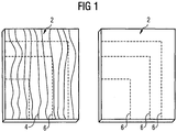
- FIG. 1 shows by way of example two front panels 2, wherein the left has a wooden surface with a grain 4 and the right has a homogeneous plastic surface.
- the front panels can have a wide variety of construction and surfaces, such as a Preßspangrundissonraj on which a wood veneer is applied, a plastic body, is laminated to the material, so that the surface is structured in three dimensions, etc.
- the front panels can also be made of solid wood.
- the dashed lines 6 are contour lines to illustrate that the front panels are needed in a variety of sizes, including non-rectangular face plates, round and oval face plates, etc. may be provided.
- FIG. 2a shows in a supervision and FIG. 2b in a side view, a device for applying predetermined patterns on a front panel. 2
- the front panel 2 is located on a conveyor 8, which contains, for example, a conveyor belt 12 moved by rollers or rollers 10, to the drive of which a motor 14 is provided.
- a portal 16 extends to the crossbar 18, a carriage 20 has been long since the crossbar 18 movably guided.
- a motor 22 is provided, the pinion 24 meshes with a toothing of the carriage 20.
- the contour and thickness sensors 30, 32 and 34 are provided, the sensor 30 detects, for example, the leading edge of the moving on the conveyor belt 12 front panel 2, the sensor 32 detects the height of the front panel 2 and the transverse bar 18 mounted sensor 34 detects the side edge of the front panel 2.
- the sensors may be optically, ultrasonically or otherwise operated and may additionally be movably arranged so that the entire geometry of the surface of the faceplate 2 may be detected before the surface enters the area under the print head 28.
- the dyeing liquid supply and the dyeing liquid supply to the printing head 28 which can be done, for example, from large storage containers placed on the carriage 20.
- a control device with a computer 36, a keyboard 38 and a screen 40 is provided. It is understood that in addition a speaker can be provided.
- the sensors 30, 32 and 34 are connected; at outputs 44 are the drives for two-dimensional movement (in the transverse direction of the conveyor belt 12 and perpendicular to its surface) for the print head 28, the control lines for driving the print head 28 and optionally the drives for moving one or more of the sensors 30, 32 and 34 as well the drive 14 of the conveyor belt 12 is connected.
- data indicating the pattern to be generated by the print head 28 is input.
- the pattern can be generated by scanning image templates in digital form, can be stored and then by appropriate control of the print head 28 and its movement relative to the front panel 2 in conjunction with the control of the drive 14 the front panel 2 can be applied.
- data processing all modern technologies are available, such as are customary for today's photo prints.
- a located on the conveyor belt 12 front panel 2 is detected by the sensors 30, 32 and 34 in terms of their position and size, so that the carriage 20 and the vertical drive of the console 26 and the print head 28 of the computer 36 according to the currently active pattern data such be controlled so that the desired pattern is formed.
- the entire contour of the front panel 2 is detected, this is done so that virtually no dyeing liquid is applied to the conveyor belt 12 and the surface of the front panel 2 is completely printed in its edge regions.
- the device described can be varied Modified way.
- the geometry of the respective faceplate is known and the faceplate 2 is placed at a respective reference position on the conveyor belt 12 and aligned in a predetermined manner with the conveyor belt 12, only the front edge of the faceplate 2 or the position of the reference position is required to detect the crossbar 18, so that the cost of the sensors can be reduced accordingly.
- the vertical mobility of the print head 28 is required because a predetermined distance between the ink nozzles of the print head 28 and the surface to be printed on the front panel 2 is required in accordance with the specifications of the print head 28 and the achievable pattern fineness.
- the computer 36 can be replaced, for example, in the conveying direction successively arranged nozzle beam, which extend across the conveyor belt 12 and each having a series of ink nozzles, which are selectively controlled by the computer 36 ,
- the nozzles of the individual nozzle bars spray in each case only one color, so that each pattern color can be generated with three nozzle bars arranged one behind the other.
- FIG. 3 shows an advantageous detail of an additionally necessary existing printing device in perspective view.
- the print head 28 is longitudinally movably guided on a carrier 50 in the direction of the double arrow and the carrier 50 is pivotable about an axis 52 perpendicular to the direction of the double arrow.
- the carrier 50 can be height-adjustable or the print head 28 can be adjusted in height relative to the carrier 50.
- FIG. 4 shows further details of possible configurations of the printing device.
- Printheads 28 2 are a bracket 26 2 pivotally by means of a drive, not shown, that on the front panel 2 2 formed projections 54 can be printed.
- the bracket 26 2 may additionally be displaced in the vertical direction and the print heads 28 2 may be pivotable about a vertical axis, for example, by appropriate support brackets 56 on the bracket 26 2 .
- FIG. 4 further illustrated printhead 28 3 is generally movable so that the side surfaces of the front panel 2 2 can be printed.
- a print head 28 which on a perpendicular and in the transverse direction of the conveyor belt 12 movable console 26 (FIGS. FIG. 2 ) is arranged pivotably about a vertical and a horizontal axis, in cooperation with a forward and a backward movement of the conveyor belt 12, each surface contour of a front panel 2 are printed, for example, also operation buttons 60, according to FIG. 5 are provided on a front panel 2.
- FIG. 6 shows an example of a decor or pattern 62 which is applied to a surface 4 provided with a grain of a front panel 2.
- the grain 4 which can be given by the wood itself and / or is also applied by printing, can be emphasized differently, depending on the homogeneous contrast color in which the surface is sprayed or printed, in the example shown in addition a rectangular frame as Decor or pattern is applied.
- FIG. 7 shows a front plate having a base body 62, for example of pressboard, on which a veneer 66 is applied from soft or absorbent wood.
- a veneer 66 is applied from soft or absorbent wood.
- the amount of dyeing liquids of the individual liquid droplets that run into one another can be influenced by the volume of the liquid droplets and the type of surface.
- FIG. 8 shows an example, up to 2 15 an overall pattern or overall visual impression can be generated in the individual by corresponding printing face plates 2 10th
- FIG. 9 can in a printhead 28 different, with different colored dye liquor charged color nozzles 70 1 to 70 4 may be provided, for example, the print heads 70 1, 70 2 and 72 3 are loaded with colors which result in their addition Black and the printhead 70 4 immediately is charged with black colored dyeing liquid.
- the previously described printing the surfaces of the front panels 2 is followed by a coating stage in which the surface formed with dyeing liquid in a predetermined pattern and / or with a predetermined background color is provided with a protective layer by this protective layer, for example as a film or as a single or Two-component synthetic resin paint or applied as a natural resin paint.
- the protective layer which is preferably transparent, makes the surface hard-wearing, chemically resistant and scratch-resistant. It further reduces the UV resistance requirements of the dyeing fluids or inks used to effect the damage.
- the protective layer can be formed by spraying, rolling or otherwise known per se.
Landscapes
- Engineering & Computer Science (AREA)
- Life Sciences & Earth Sciences (AREA)
- Wood Science & Technology (AREA)
- Manufacturing & Machinery (AREA)
- Mechanical Engineering (AREA)
- Forests & Forestry (AREA)
- Ink Jet (AREA)
- Application Of Or Painting With Fluid Materials (AREA)
- Printing Methods (AREA)
- Laminated Bodies (AREA)
- Automatic Assembly (AREA)
Description
- Die Erfindung betrifft ein Verfahren zum Herstellen von Bauteilen mit vorbestimmtem Oberflächenaussehen, insbesondere von Frontplatten von Küchenelementen, gemäß dem Obergegriff von Anspruch 1.
- Ein gattungsgemäßes Verfahren ist aus der
GB-A-2 212 761 - Ein Konstruktionsmerkmal üblicher Küchen liegt darin, daß unterschiedlichste Küchenelemente, Schubladen, Schränke, Elektrogeräte usw. mit Frontplatten versehen werden, die der Küche ein eigenes und gefälliges Aussehen verleihen. Die Vielzahl von Frontplattengrößen und die Vielzahl von von den Kunden gewünschten Oberflächen, die unterschiedliche Holzarten, Kunststoffoberflächen, unterschiedliche Farben und Muster umfassen, führt zu einer außerordentlich kostenintensiven Produktion mit großer Lagerhaltung. Beispielweise werden Frontplatten aus unterschiedlichem Massivholz oder mit unterschiedlichen Holzfurnieren hergestellt, die dann in der gewünschten Farbe gebeizt und oberflächenversiegelt werden.
- Der Erfindung liegt die Aufgabe zu Grunde, die vorgenannte Problematik zu mildern.
- Das Verfahren gemäß Anspruch 1 liefert eine Lösung für das vorgenannte Problem.
- Mit dem erfindungsgemäßen Verfahren können aus Formteilen, deren Form der der herzustellenden Bauteile entspricht, Bauteile mit unterschiedlichstem Aussehen hergestellt werden, obwohl die bedruckten Formteile gleiche Oberflächen oder Formteile verwendet werden, die hinsichtlich ihres Oberflächenmaterials eine wesentlich geringere Vielfalt aufweisen als die bedruckten, herzustellenden Bauteile. Beispielsweise kann mit Formteilen mit lediglich zwei Arten von Oberflächen gearbeitet werden, um eine außerordentlich große Vielfalt zu erzielen. Die eine Art von Formbauteilen weist eine Kunststoffoberfläche auf und die andere Art von Formbauteilen weist eine Holzfurnieroberfläche auf. Auf die Kunststoffoberfläche können unterschiedlichste Farben und/oder Muster gedruckt werden, um ein entsprechendes Aussehen zu erzeugen. Auf die Holzfumieroberfläche können unterschiedlichste Holzmaserungen aufgedruckt werden, die das Aussehen unterschiedlichster Holzarten mit unterschiedlichsten Einfärbungen ergeben, ohne dass die jeweilige Holzart tatsächlich verwendet werden muß. Überraschenderweise hat sich herausgestellt, dass eine Grundmaserung der Furnieroberfläche oder auch einer Vollholzoberfläche einem Bedrukken mit anderen Maserungen nicht entgegensteht und durch entsprechende Abstimmung der Farbintensitäten das Aussehen der aufgedruckten Maserung nicht nachteilig beeinflußt. Mit dem erfindungsgemäßen Verfahren ist es somit möglich, eine außerordentlich hohe Aussehensvielfalt, d.h. insbesondere vom Kunden gewünschte Vielfalt mit einer geringen Vielfalt von Rohteilen zu erzeugen.
- Die Unteransprüche 2 bis 4 sind auf vorteilhafte Durchführungsformen des erfindungsgemäßen Verfahrens gerichtet.
- Mit den Merkmalen des Anspruchs 3 können zu bedruckende Oberflächen derart vorbehandelt werden, dass sie Färbeflüssigkeiten, die wegen des verwendeten Druckverfahrens, beispielsweise in einem Tintendruckstrahlverfahren, bestimmten Einschränkungen unterworfen sind, gut aufnehmen. Auf diese Weise können die zu bedruckende Oberfläche und die Färbeflüssigkeiten aufeinander abgestimmt werden. Bei Holzoberflächen kann eine Vorbehandlung auch darin bestehen, dass das Holz in vorbestimmter Weise in Art einer Lasur behandelt wird, dass seine Porosität bzw. sein Flüssigkeitsaufnahmevermögen auf das dann verwendete Druckverfahren abgestimmt wird oder das Holz mit einer bestimmten Grundtönung versehen wird.
- Mit den Merkmalen des Anspruch 4 läßt sich die bedruckte Oberfläche versiegeln oder mit sonstigen Beschichtungen versehen, die beispielsweise mechanisch sehr unempfindlich sind, für UV-Licht nicht durchlässig sind usw.
- Die Erfindung ist überall dort einsetzbar, wo an Bauteilen bezüglich des Aussehens eine hohe Vielfalt vor Kunde mit geringen Kosten erreicht werden soll. Besonders vorteilhaft ist die Erfindung bei flächigen Bauteilen einsetzbar, bei denen aus plattenartigem Rohmaterial zunächst Zuschnitte mit vorbestimmter Form hergestellt werden, die dann das gewünschte Oberflächenaussehen erhalten. Ein Einsatzgebiet, für die sich die Erfindung besonders gut eignet, ist die Möbelindustrie, in der Möbel, beispielsweise auch Küchenmöbel, aus flächigen Bauteilen zusammengesetzt werden, die nach innen und nach außen unterschiedliches Aussehen haben sollen, wobei insbesondere das Aussehen von außen in hohem Maße kundenindividuell und qualitativ hochwertig sein muß.
- Die Erfindung wird im folgenden anhand schematischer Zeichnungen beispielsweise und mit weiteren Einzelheiten erläutert.
- Es stellen dar:
- Figur 1
- zwei Frontplatten mit unterschiedlicher Oberflächenstruktur,
- Figur 2
- eine schematische Ansicht einer zur Durchführung das erfindungsgemäßen Verfahrens Vorrichtung,
- Figur 3
- eine schematische Ansicht einer in der Vorrichtung aus
Figur 2 ent- haltenen Baugruppe, Vorrichtung ausFigur 2 enthaltenen - Figur 4
- ein Beispiel von weiteren in der Vorrichtung aus
Figur 2 enthaltenen Baugruppen, - Figur 5
- ein Detail der Vorrichtung zum Bedrucken von Handhabungsknöpfen,
- Figur 6
- eine mit einem Dekor versehene Frontplatte,
- Figur 7
- einen Querschnitt durch eine Frontplatte zu Erläuterung des Bedruckens,
- Figur 8
- eine Gruppe von Frontplatten,
- Figur 9
- einen schematischen Querschnitt durch einen Druckkopf,
-
Figur 1 zeigt beispielhaft zwei Frontplatten 2, wobei die linke eine Holzoberfläche mit einer Maserung 4 aufweist und die rechte eine homogene Kunststoffoberfläche aufweist. Die Frontplatten können unterschiedlichsten Aufbau und Oberflächen haben, beispielsweise einen Preßspangrundkörper, auf den ein Holzfurnier aufgebracht ist, einen Kunststoffgrundkörper, auf den Material aufkaschiert ist, so daß die Oberfläche dreidimensional strukturiert ist, usw. - Die Frontplatten können auch aus Massivholz sein.
- Die gestrichelt eingezeichneten Linien 6 sind Konturlinien zur Verdeutlichung, daß die Frontplatten in unterschiedlichsten Größen benötigt werden, wobei auch nicht rechtwinklige Frontplatten, runde und ovale Frontplatten usw. vorgesehen sein können.
-
Figur 2a zeigt in einer Aufsicht undFigur 2b in einer Seitenansicht eine Vorrichtung zum Aufbringen vorbestimmter Muster auf eine Frontplatte 2. - Die Frontplatte 2 befindet sich auf einer Fördereinrichtung 8, die beispielsweise ein über Rollen bzw. Walzen 10 bewegtes Förderband 12 enthält, zu dessen Antrieb ein Motor 14 vorgesehen ist.
- Quer über das Förderband 12 erstreckt sich ein Portal 16, an dessen Querbalken 18 ein Wagen 20 längst des Querbalkens 18 beweglich geführt ist. Zum Antrieb des Wagens ist ein Motor 22 vorgesehen, dessen Ritzel 24 mit einer Verzahnung des Wagens 20 kämmt.
- An dem Wagen 20 ist mittels eines nicht dargestellten Antriebs eine Konsole 26 in Richtung des Doppelpfeils (
Figur 2b ) senkrecht verschiebbar geführt, an deren Ende ein Druckkopf 28 befestigt ist, der beispielsweise in Art eines Druckkopfes aufgebaut ist, wie er in Tintenstrahldruckern bzw. Ink-Jet oder Bubble-Jet Drukkern verwendet wird, wobei aus Farbdüsen des Druckkopfes Färbeflüssigkeitstropfen abspritzbar sind. - Zur Erfassung der Position der Frontplatte 2, deren Kontur und Dicke sind Sensoren 30, 32 und 34 vorgesehen, wobei der Sensor 30 beispielsweise die Vorderkante die auf dem Förderband 12 bewegten Frontplatte 2 erfaßt, der Sensor 32 die Höhe der Frontplatte 2 erfaßt und der an dem Querbalken 18 angebrachte Sensor 34 die Seitenkante der Frontplatte 2 erfaßt.
- Die Sensoren können optisch, mit Ultraschall oder sonstwie arbeiten und können zusätzlich beweglich angeordnet sein, so daß die gesamte Geometrie der Oberfläche der Frontplatte 2 jeweils erfaßt werden kann, bevor die Oberfläche in den Bereich unter dem Druckkopf 28 kommt.
- In den Figuren nicht eingezeichnet ist der Färbeflüssigkeitsvorrat und die Färbellüssigkeitsbeschikkung für den Druckkopf 28, die beispielsweise aus großen Vorratsbehältern erfolgen kann, die auf dem Wagen 20 abgeordnet sind.
- Zur Steuerung der Vorrichtung ist ein Steuergerät mit einem Computer 36, einer Tastatur 38 und einem Bildschirm 40 vorgesehen. Es versteht sich, daß zusätzlich ein Lautsprecher vorgesehen sein kann.
- An Eingänge 42 des Computers 36 sind die Sensoren 30, 32 und 34 angeschlossen; an Ausgänge 44 sind die Antriebe zur zweidimensionalen Bewegung (in Querrichtung des Förderbandes 12 und senkrecht zu dessen Oberfläche) für den Druckkopf 28, die Steuerleitungen zur Ansteuerung des Druckkopfes 28 und gegebenenfalls die Antriebe zur Bewegung einer oder mehrerer der Sensoren 30, 32 und 34 sowie der Antrieb 14 des Förderbandes 12 angeschlossen.
- Über einen weiteren Eingang 46 werden Daten eingegeben, die das Muster angeben, das von dem Druckkopf 28 erzeugt werden soll. Für die Ausbildung dieser Muster bestehen alle Freiheitsgrade, wobei die Muster durch Scannen von Bildvorlagen in digitaler Form erzeugt werden können, gespeichert werden können und dann durch entsprechende Ansteuerung des Druckkopfes 28 sowie dessen Bewegung relativ zur Frontplatte 2 in Verbindung mit der Steuerung des Antriebs 14 auf die Frontplatte 2 aufgebracht werden können. Bezüglich der Datenverarbeitung stehen alle modernen Technologien zur Verfügung, wie sie beispielsweise für heutige Fotodrucke üblich sind.
- Aufbau und Arbeitsweise der einzelnen Element der Vorrichtung sind an sich bekannt und werden daher nicht erläutert.
- Eine auf dem Förderband 12 befindliche Frontplatte 2 wird von den Sensoren 30, 32 und 34 hinsichtlich ihrer Lage und Größe erkannt, so daß der Wagen 20 und der senkrechte Antrieb der Konsole 26 sowie der Druckkopf 28 von dem Computer 36 entsprechend den gerade wirksamen Musterdaten derart gesteuert werden, daß das erwünschte Muster ausgebildet wird. Wenn die gesamte Kontur der Frontplatte 2 erfaßt wird, geschieht dies derart, daß praktisch keine Färbeflüssigkeit auf das Förderband 12 aufgebracht wird und die Oberfläche der Frontplatte 2 auch in ihren Randbereichen vollständig bedruckt ist.
- Die beschriebene Vorrichtung kann in vielfältiger Weise abgeändert werden. Beispielsweise ist, wenn die Geometrie der jeweiligen Frontplatte bekannt ist und die Frontplatte 2 an einer jeweiligen Bezugsposition auf das Förderband 12 aufgelegt wird und in vorbestimmter Weise zum Förderband 12 ausgerichtet ist, nur erforderlich, die Vorderkante der Frontplatte 2 bzw. die Lage der Bezugsposition relativ zum Querbalken 18 zu erfassen, so daß der Aufwand für die Sensoren entsprechend vermindert werden kann. Die senkrechte Bewegbarkeit des Druckkopfes 28 ist erforderlich, da entsprechend den Spezifikationen des Druckkopfes 28 und der erzielbaren Musterfeinheit ein vorbestimmter Abstand zwischen den Farbdüsen des Druckkopfes 28 und der zu bedruckenden Oberfläche der Frontplatte 2 erforderlich ist.
- Der in
Figur 2 dargestellte, einzige bewegliche Druckkopf mit mehreren Farbdüsen (nicht dargestellt) zum Abspritzen unterschiedlicher Färbeflüssigkeiten kann beispielsweise durch in Förderrichtung hintereinander angeordnete Düsenbalken ersetzt werden, die sich quer über das Förderband 12 erstrecken und jeweils eine Reihe von Farbdüsen aufweisen, die selektiv vom Computer 36 ansteuerbar sind. Die Düsen der einzelnen Düsenbalken verspritzen jeweils nur eine Farbe, so daß jede Musterfarbe mit drei hintereinander angeordneten Düsenbalken erzeugbar ist. -
Figur 3 zeigt ein vorteilhaftes Detail einer erforderlichenfalls zusätzlich vorhandenen Druckeinrichtung in perspektivischer Darstellung. Bei dieser Druckeinrichtung ist der Druckkopf 28 an einem Träger 50 längsbeweglich in Richtung des Doppelpfeils geführt und ist der Träger 50 um eine zur Richtung des Doppelpfeils senkrechte Achse 52 schwenkbar. Zusätzlich kann der Träger 50 höhenverstellbar oder der Druckkopf 28 relativ zum Träger 50 höhenverstellbar sein. - Mit der Anordnung ist es, wie unmittelbar einsichtig, möglich, Seitenflächen der Frontplatte 2 zu bedrucken, auch wenn die Seitenflächen schräg zur Förderrichtung des Förderbandes 12 gerichtet sind.
-
Figur 4 zeigt weitere Details möglicher Ausbildungen der Druckeinrichtung. Druckköpfe 282 sind einer Konsole 262 mittels eines nicht dargestellten Antriebs derart schwenkbar, daß an der Frontplatte 22 ausgebildete Vorsprünge 54 bedruckt werden können. Die Konsole 262 kann zusätzlich in senkrechter Richtung verschiebbar sein und die Druckköpfe 282 können beispielsweise durch entsprechende Lagerung von Tragarmen 56 an der Konsole 262 um eine senkrechte Achse schwenkbar sein. Durch die damit geschaffenen kinematischen Möglichkeiten ist es möglich, die Vorsprünge 54 derart zu bedrucken, daß sich die Farbdüsen der Druckköpfe 282 jeweils in einem vorbestimmten Abstand von der Oberfläche und senkrecht zur Oberflächenrichtung gerichtet befinden, wodurch sich hochqualitative Muster ausbilden lassen. - Der in
Figur 4 weiter dargestellte Druckkopf 283 ist insgesamt derart beweglich, daß die Seitenflächen der Frontplatte 22 bedruckbar sind. - Wie aus den bisherigen Zeichnungen unmittelbar ersichtlich, kann mit einem Druckkopf 28, der an einer senkrecht und in Querrichtung des Förderbandes 12 beweglichen Konsole 26 (
Figur 2 ) um eine senkrechte und eine waagrechte Achse schwenkbar angeordnet ist, im Zusammenwirken mit einer Vorwärts- und einer Rückwärtsbewegung des Förderbandes 12 jede Oberflächenkontur einer Frontplatte 2 bedruckt werden, beispielsweise auch Betätigungsknöpfe 60, die gemäßFigur 5 an einer Frontplatte 2 vorgesehen sind. -
Figur 6 zeigt ein Beispiel eines Dekors bzw. Musters 62, das auf eine mit einer Maserung 4 versehene Oberfläche einer Frontplatte 2 aufgebracht ist. Die Maserung 4, die durch das Holz selbst gegeben sein kann und/oder ebenfalls durch Bedrucken aufgebracht ist, kann unterschiedlich betont werden, je nach homogener Kontrastfarbe, in der die Oberfläche bespritzt bzw. bedruckt ist, wobei im dargestellten Beispiel zusätzlich ein rechteckiger Rahmen als Dekor bzw. Muster aufgebracht ist. -
Figur 7 zeigt eine Frontplatte, die einen Grundkörper 62, beispielsweise aus Preßspan, aufweist, auf den ein Furnier 66 aus weichem bzw. saugfähigem Holz aufgebracht ist. Wenn auf diese Art einer saugfähigen Oberfläche Flüssigkeitströpfchen 66 aufgebracht werden, verlaufen diese ähnlich wie bei faserigem oder feuchtem Papier seitlich und fließen ineinander, wodurch optisch sehr gefällige Muster erzeugt werden können, wenn unterschiedlich gefärbte Flüssigkeitströpfchen 66 mit ihren Randbereichen ineinander laufen. - Die Menge der Färbeflüssigkeiten der einzelnen Flüssigkeitströpfchen, die ineinander läuft, kann durch das Volumen der Flüssigkeitströpfchen und die Art der Oberfläche beeinflußt werden.
-
Figur 8 zeigt ein Beispiel, in dem durch entsprechende Bedruckung einzelner Frontplatten 210 bis 215 ein Gesamtmuster bzw. optischer Gesamteindruck erzeugt werden kann. - Gemäß
Figur 9 können in einem Druckkopf 28 unterschiedliche, mit unterschiedlich gefärbter Färbeflüssigkeit beschickte Farbdüsen 701 bis 704 vorgesehen sein, wobei beispielsweise die Druckköpfe 701, 702 und 723 mit Farben beschickt werden, die in ihrer Addition Schwarz ergeben und der Druckkopf 704 unmittelbar mit schwarz gefärbter Färbeflüssigkeit beschickt wird. - Vorzugsweise wird der bisher geschilderten Bedruckung der Oberflächen der Frontplatten 2 eine Beschichtungsstufe nachgeschaltet, in der die mit Färbeflüssigkeit in einem vorbestimmten Muster und/oder mit einer vorbestimmten Hintergrundfarbe ausgebildete Oberfläche mit einer Schutzschicht versehen wird, indem diese Schutzschicht beispielsweise als Folie oder als Ein- oder Zweikomponenten-Kunstharzlack oder als Naturharzlack aufgebracht wird. Die Schutzschicht, die vorzugsweise transparent ist, macht die Oberfläche strapazierfähig, chemisch unempfindlich und kratzfest. Sie vermindert des weiteren die Anforderungen an die UV-Beständigkeit der verwendeten Färbeflüssigkeiten bzw. Tinten, mit denen die Bedrukkung erfolgt. Die Schutzschicht kann durch Spritzen, Rollen oder auch sonstige, an sich bekannte Weise ausgebildet werden.
-
- 2
- Frontplatte
- 4
- Maserung
- 6
- Konturlinien
- 8
- Fördereinrichtung
- 10
- Walze
- 12
- Förderband
- 14
- Motor
- 16
- Portal
- 18
- Querbalken
- 20
- Wagen
- 22
- Motor
- 24
- Ritzel
- 26
- Konsole
- 28
- Druckkopf
- 30
- Sensor
- 30
- Sensor
- 34
- Sensor
- 36
- Computer
- 38
- Tastenfeld
- 40
- Bildschirm
- 42
- Eingänge
- 44
- Ausgänge
- 46
- Eingang
- 50
- Träger
- 52
- Achse
- 54
- Vorsprung
- 56
- Tragarm
- 58
- Tragarm
- 60
- Betätigungsknopf
- 62
- Muster
- 64
- Grundkörper
- 66
- Flüssigkeitströpfchen
- 70
- Farbdüse
Claims (4)
- Verfahren zum Herstellen von Bauteilen (2) mit vorbestimmtem Oberflächenaussehen, insbesondere von Frontplatten von Küchenelementen,
bei welchem Verfahren die Bauteile (2) mittels eines hinsichtlich des sich ergebenden Aussehens programmierbaren Druckverfahrens zur Ausbildung eines vorbestimmten Musters (62) bedruckt werden, nämlich einem Tintenstrahldruckverfahren, bei dem Färbeflüssigkeiten unterschiedlicher Farbe aus unterschiedlichen Düsen (70) abgespritzt werden,
wobei das Bauteil (2) eine saugfähige Holzoberfläche aufweist, dadurch gekennzeichnet, dass unterschiedlich gefärbte Flüssigkeitströpfchen (66) mit ihren Randbereichen ineinanderlaufen,
wobei die Menge der ineinanderlaufenden Färbeflüssigkeiten der einzelnen Flüssigkeitströpfchen (66) durch eine entsprechende Wahl des Volumens der Flüssigkeitströpfchen (66) und der Art der Holzoberfläche bestimmt wird. - Verfahren nach Anspruch 1, wobei dreidimensionale Oberflächen bedruckt werden.
- Verfahren nach Anspruch 1 oder 2 wobei die zu bedruckende Oberfläche vordem Bedrucken vorbehandelt wird.
- Verfahren nach einem der Ansprüche 1 bis 3, wobei die mit dem vorbestimmten Muster bedruckte Oberfläche mit einer durchsichtigen Beschichtung versehen wird.
Priority Applications (1)
| Application Number | Priority Date | Filing Date | Title |
|---|---|---|---|
| EP09165481.4A EP2133154B1 (de) | 2000-06-26 | 2001-06-25 | Verfahren, Vorrichtung und System zum Herstellen von Bauteilen mit vorbestimmtem Oberflächenaussehen, insbesondere von Frontplatten von Küchenelementen |
Applications Claiming Priority (3)
| Application Number | Priority Date | Filing Date | Title |
|---|---|---|---|
| DE10031030A DE10031030B4 (de) | 2000-06-26 | 2000-06-26 | Verfahren und Vorrichtung zum Herstellen flächiger Bauteile mit vorbestimmtem Oberflächenaussehen und flächiges Bauteil, insbesondere Frontplatte eines Küchenelements |
| DE10031030 | 2000-06-26 | ||
| PCT/EP2001/007159 WO2002000449A1 (de) | 2000-06-26 | 2001-06-25 | Verfahren, vorrichtung und system zum herstellen von bauteilen mit vorbestimmtem oberflächenaussehen, insbesondere von frontplatten von küchenelementen |
Related Child Applications (3)
| Application Number | Title | Priority Date | Filing Date |
|---|---|---|---|
| EP09165481.4A Division-Into EP2133154B1 (de) | 2000-06-26 | 2001-06-25 | Verfahren, Vorrichtung und System zum Herstellen von Bauteilen mit vorbestimmtem Oberflächenaussehen, insbesondere von Frontplatten von Küchenelementen |
| EP09165481.4A Division EP2133154B1 (de) | 2000-06-26 | 2001-06-25 | Verfahren, Vorrichtung und System zum Herstellen von Bauteilen mit vorbestimmtem Oberflächenaussehen, insbesondere von Frontplatten von Küchenelementen |
| EP09165481.4 Division-Into | 2009-07-15 |
Publications (4)
| Publication Number | Publication Date |
|---|---|
| EP1294578A1 EP1294578A1 (de) | 2003-03-26 |
| EP1294578B1 EP1294578B1 (de) | 2011-06-08 |
| EP1294578B2 true EP1294578B2 (de) | 2018-10-17 |
| EP1294578B9 EP1294578B9 (de) | 2019-05-15 |
Family
ID=7646807
Family Applications (2)
| Application Number | Title | Priority Date | Filing Date |
|---|---|---|---|
| EP09165481.4A Revoked EP2133154B1 (de) | 2000-06-26 | 2001-06-25 | Verfahren, Vorrichtung und System zum Herstellen von Bauteilen mit vorbestimmtem Oberflächenaussehen, insbesondere von Frontplatten von Küchenelementen |
| EP01956502.7A Expired - Lifetime EP1294578B9 (de) | 2000-06-26 | 2001-06-25 | Verfahren zum herstellen von bauteilen mit vorbestimmtem oberflächenaussehen, insbesondere von frontplatten von küchenelementen |
Family Applications Before (1)
| Application Number | Title | Priority Date | Filing Date |
|---|---|---|---|
| EP09165481.4A Revoked EP2133154B1 (de) | 2000-06-26 | 2001-06-25 | Verfahren, Vorrichtung und System zum Herstellen von Bauteilen mit vorbestimmtem Oberflächenaussehen, insbesondere von Frontplatten von Küchenelementen |
Country Status (10)
| Country | Link |
|---|---|
| US (1) | US7357959B2 (de) |
| EP (2) | EP2133154B1 (de) |
| CN (1) | CN1176815C (de) |
| AT (1) | ATE512004T1 (de) |
| AU (1) | AU2001278466A1 (de) |
| DE (1) | DE10031030B4 (de) |
| DK (1) | DK1294578T3 (de) |
| ES (2) | ES2364625T5 (de) |
| PT (2) | PT2133154E (de) |
| WO (1) | WO2002000449A1 (de) |
Families Citing this family (130)
| Publication number | Priority date | Publication date | Assignee | Title |
|---|---|---|---|---|
| DE60335613D1 (de) | 2002-04-03 | 2011-02-17 | Masonite Corp | Verfahren und vorrichtung zur erzeugung eines bildes auf einem gegenstand, und ein durch das verfahren hergestellte gegenstand |
| DE10224128A1 (de) * | 2002-05-29 | 2003-12-18 | Schmid Rhyner Ag Adliswil | Verfahren zum Auftrag von Beschichtungen auf Oberflächen |
| DE10302484A1 (de) * | 2003-01-23 | 2004-08-05 | Abb Patent Gmbh | Verfahren zum Bedrucken von insbesondere glatten Oberflächen |
| DE10318988A1 (de) * | 2003-04-25 | 2004-11-18 | Tampoprint Ag | Sichtelement |
| WO2004096561A1 (de) * | 2003-04-25 | 2004-11-11 | Tampoprint Ag | Sichtelement |
| EP1624755A1 (de) | 2003-05-15 | 2006-02-15 | Arch UK Biocides Limited | Zusammensetzung enthaltend ein säuerlichen copolymer und eine antimikrobielle stoff und dessen verwendung |
| DE10323412B4 (de) | 2003-05-23 | 2007-07-05 | Bauer, Jörg R. | Verfahren und Vorrichtung zum Herstellen eines Bauteils mit einer Oberfläche vorbestimmten Aussehens |
| US20060162879A1 (en) * | 2003-07-13 | 2006-07-27 | Tinker Larry C | Compounding of fibrillated fiber |
| US20050183243A1 (en) * | 2003-07-13 | 2005-08-25 | Tinker Larry C. | Fibrillation of natural fiber |
| US7477962B2 (en) | 2003-10-27 | 2009-01-13 | Yamaha Corporation | Method for manufacturing wooden decorative material |
| DE202004000662U1 (de) | 2004-01-17 | 2004-04-08 | Homag Holzbearbeitungssysteme Ag | Maschine zum Bedrucken der Schmalseiten plattenförmiger Werkstücke |
| US7360853B2 (en) * | 2004-03-04 | 2008-04-22 | Fujifilm Dimatix, Inc. | Morphology-corrected printing |
| US8068245B2 (en) * | 2004-10-15 | 2011-11-29 | Fujifilm Dimatix, Inc. | Printing device communication protocol |
| US7911625B2 (en) * | 2004-10-15 | 2011-03-22 | Fujifilm Dimatrix, Inc. | Printing system software architecture |
| US8085428B2 (en) * | 2004-10-15 | 2011-12-27 | Fujifilm Dimatix, Inc. | Print systems and techniques |
| US8199342B2 (en) * | 2004-10-29 | 2012-06-12 | Fujifilm Dimatix, Inc. | Tailoring image data packets to properties of print heads |
| EP1796919B2 (de) * | 2004-12-16 | 2016-03-23 | Flooring Industries Limited, SARL | Ein holzmuster auf ihrer fläche imitierende fussbodenplatte und herstellungsverfahren |
| ITTV20050035A1 (it) * | 2005-03-04 | 2006-09-05 | Roberto Brao | Metodo per realizzare un mobile decorato. |
| DE502005000877D1 (de) * | 2005-04-28 | 2007-07-26 | Homag Holzbearbeitungssysteme | Vorrichtung und Verfahren zum Bemustern der Schmalseiten von plattenförmigen Werkstücken |
| US20060275532A1 (en) * | 2005-05-11 | 2006-12-07 | Dechert Gary J | Ink jet printing of snacks with high reliability and image quality |
| FR2886880B1 (fr) | 2005-06-14 | 2008-10-03 | Mgi France Sa | Machine numerique a jet pour depose d'un revetement sur un substrat |
| DE102005059540A1 (de) * | 2005-08-19 | 2007-06-14 | Bauer, Jörg R. | Lösbar aneinander zu befestigende, flächige Bauteile, sowie Bauteil |
| US20070206038A1 (en) * | 2006-03-03 | 2007-09-06 | Richard Baker | Ink jet printing with multiple conveyors |
| EP1832429A3 (de) | 2006-03-08 | 2008-05-28 | Homag Holzbearbeitungssysteme AG | Vorrichtung zum Bemustern von Werkstücken |
| EP1839883B1 (de) | 2006-03-08 | 2016-08-24 | Homag Holzbearbeitungssysteme AG | Verfahren und vorrichtung zum bedrucken plattförmiger werkstücke |
| PL2065206T3 (pl) | 2006-03-08 | 2011-05-31 | Homag Holzbearbeitungssysteme Ag | Urządzenie do uszlachetniania detali |
| DE102006014644A1 (de) * | 2006-03-30 | 2007-10-04 | Robert Bürkle GmbH | Vorrichtung zum konturgenauen Drucken von Dekorbildern auf flächige Werkstücke |
| BE1017157A3 (nl) | 2006-06-02 | 2008-03-04 | Flooring Ind Ltd | Vloerbekleding, vloerelement en werkwijze voor het vervaardigen van vloerelementen. |
| ITMI20061227A1 (it) | 2006-06-26 | 2007-12-27 | Dante Frati | Procedimento per stampare superfici di elementi piani a base di legno |
| DE102006030624A1 (de) † | 2006-07-04 | 2008-01-17 | Rehau Ag + Co | Verfahren zum Herstellen und Montieren einer bedruckten Kantenleiste |
| DE102006034060B4 (de) | 2006-07-20 | 2009-01-15 | Ball Packaging Europe Gmbh | Verfahren und Vorrichtung zum Dekorieren einer unebenen Fläche an einem formstabilen Objekt |
| DE502006005293D1 (de) * | 2006-08-25 | 2009-12-17 | Homag Holzbearbeitungssysteme | Vorrichtung zum Bemustern von Werkstücken |
| DE102006052293C5 (de) * | 2006-11-03 | 2011-02-03 | Kronotec Ag | Holzwerkstoffplatte mit Echtholzfurnier und Verfahren zu ihrer Herstellung |
| US7914098B2 (en) * | 2006-11-07 | 2011-03-29 | Homag Holzbearbeitungssysteme Ag | Device for patterning workpieces |
| CN101177078B (zh) * | 2006-11-12 | 2010-05-12 | 朱东奇 | 一种竹、木制品印花工艺 |
| DE102006057961A1 (de) * | 2006-12-08 | 2008-06-12 | Bauer, Jörg R. | Verfahren und Vorrichtung zum Erzeugen einer Folge individueller Einzelmuster aus einem Urmuster sowie Vorrichtung zum Drucken solcher Einzelmuster |
| JP5787203B2 (ja) * | 2006-12-20 | 2015-09-30 | クルニアワン,スリャ | より自然な木目を木材表面に形成する方法および装置 |
| ES2402367T3 (es) * | 2006-12-20 | 2013-05-03 | Homag Holzbearbeitungssysteme Ag | Dispositivo y procedimiento para recubrir piezas |
| AU2008216380A1 (en) * | 2007-02-13 | 2008-08-21 | John Desautels | A personal affector machine |
| DE502007002035D1 (de) | 2007-03-27 | 2009-12-31 | Homag Holzbearbeitungssysteme | Verfahren zum Bedrucken eines dreidimensionalen Behälters |
| DE102007017503B3 (de) * | 2007-04-13 | 2008-11-06 | Bauer, Jörg R. | Verfahren zum Herstellen eines Bauteils mit einer bedruckten Echtholzoberfläche sowie nach dem Verfahren hergestelltes Bauteil |
| ITMO20070134A1 (it) * | 2007-04-17 | 2008-10-18 | Gruppo Barbieri & Tarozzi S P A | "metodo ed impianto di decoro per decorare manufatti ceramici" |
| DE102007021767A1 (de) | 2007-05-09 | 2008-11-13 | Bauer, Jörg R. | Verfahren und Vorrichtung zum Bedrucken eines Bauteils mit zwei zueinander geneigten Oberflächenbereichen mittels eines digitalen Druckverfahrens |
| ES2564242T3 (es) * | 2007-05-10 | 2016-03-21 | Homag Holzbearbeitungssysteme Ag | Procedimiento y dispositivo para el revestimiento de una superficie |
| DK2158095T3 (en) | 2007-05-27 | 2017-07-31 | Thomas Schneider | FLAT ELEMENT AND PROCEDURE FOR PREPARING THIS |
| US20080314513A1 (en) * | 2007-06-19 | 2008-12-25 | Achim Gauss | Device for imparting a pattern onto the surface of work pieces |
| US7963246B1 (en) * | 2007-08-14 | 2011-06-21 | Henline Adhesive Equipment Co., Inc. | Apparatus for controlled application of an adhesive bead to a workpiece |
| US20090120249A1 (en) * | 2007-11-14 | 2009-05-14 | Achim Gauss | Device For Refining Workpieces |
| US8186399B2 (en) * | 2008-03-10 | 2012-05-29 | Unilin Flooring Nc Llc | Automated floor board texturing cell and method |
| WO2009149163A2 (en) | 2008-06-06 | 2009-12-10 | Fujifilm Dimatix, Inc. | Sensing objects for printing |
| DE102008063837A1 (de) | 2008-12-19 | 2010-06-24 | Mankiewicz Gebr. & Co. Gmbh & Co Kg | Beschichtung und deren Herstellung mittels Inkjet-Druckverfahren |
| DE102009004877B4 (de) * | 2009-01-16 | 2015-10-08 | Jörg R. Bauer | Bauteil mit einem Grundkörper und einer darauf mittels eines digitalen Beschichtungssystems aufgebrachten Schicht |
| TW201029856A (en) * | 2009-01-16 | 2010-08-16 | Echelon Laser Systems Lp | Surface marked articles, related methods and systems |
| BE1018630A5 (nl) * | 2009-01-20 | 2011-05-03 | Flooring Ind Ltd Sarl | Werkwijzen voor het vervaardigen van panelen en paneel hierbij bekomen. |
| AT507848B1 (de) * | 2009-01-29 | 2011-06-15 | Durst Phototechnik Digital Technology Gmbh | Vorrichtung und verfahren zum aufbringen von fluidtropfen |
| EP2213476A1 (de) * | 2009-01-30 | 2010-08-04 | Spanolux N.V.- DIV. Balterio | Verfahren zur Herstellung einer Laminatplatte, Vorrichtung und Laminatplatte |
| US7991498B2 (en) * | 2009-02-03 | 2011-08-02 | Objet Geometries Ltd. | Method and system for building painted three-dimensional objects |
| US20100236175A1 (en) * | 2009-03-17 | 2010-09-23 | Tapco International Corporation | Multi-colored snap-lock siding panel, and system and method for making the same |
| DE202009018533U1 (de) * | 2009-05-19 | 2012-05-30 | Pas Deutschland Gmbh | Vorrichtung zum Bedrucken einer nicht-ebenen Oberfläche, sowie Blendenanordnung und Haushaltsgerät |
| BE1018943A3 (nl) * | 2009-10-01 | 2011-11-08 | Flooring Ind Ltd Sarl | Werkwijzen voor het vervaardigen van panelen en paneel hierbij bekomen. |
| BE1018954A3 (nl) | 2009-10-14 | 2011-11-08 | Flooring Ind Ltd Sarl | Werkwijzen voor het vervaardigen van panelen en paneel hierbij bekomen. |
| US8585956B1 (en) | 2009-10-23 | 2013-11-19 | Therma-Tru, Inc. | Systems and methods for laser marking work pieces |
| EP4198221A1 (de) | 2009-12-22 | 2023-06-21 | Flooring Industries Limited, SARL | Paneel, belag und verfahren zur installation solcher paneele |
| DE102010008295A1 (de) | 2010-02-17 | 2011-08-18 | Dieffenbacher System Automation GmbH, 75031 | Vorrichtung und Verfahren zum Bedrucken von Oberflächen von Werkstoffplatten, insbesondere Holzplatten, mit einer mehrfarbigen Abbildung |
| DK2363299T3 (da) | 2010-03-05 | 2013-01-28 | Spanolux N V Div Balterio | Fremgangsmåde til fremstilling af en gulvplade |
| BE1019501A5 (nl) | 2010-05-10 | 2012-08-07 | Flooring Ind Ltd Sarl | Vloerpaneel en werkwijze voor het vervaardigen van vloerpanelen. |
| US8925275B2 (en) | 2010-05-10 | 2015-01-06 | Flooring Industries Limited, Sarl | Floor panel |
| BE1019331A5 (nl) | 2010-05-10 | 2012-06-05 | Flooring Ind Ltd Sarl | Vloerpaneel en werkwijzen voor het vervaardigen van vloerpanelen. |
| EP3858639B1 (de) * | 2010-06-30 | 2023-08-23 | Flooring Technologies Ltd. | Verfahren zum herstellen von paneelen |
| DE102010038332B4 (de) | 2010-07-23 | 2018-03-08 | Kba-Metalprint Gmbh | Beschichtungsverfahren zumindest einer Seitenfläche eines tafelförmigen Gutes |
| DE102010054578A1 (de) * | 2010-12-15 | 2012-06-21 | Erfurt & Sohn Kg | Bahnen, die ein Bild und/oder eine Grafik bilden |
| TW201231169A (en) * | 2011-01-27 | 2012-08-01 | Asustek Comp Inc | Casing printing method and printing apparatus thereof |
| AT511152A1 (de) * | 2011-02-22 | 2012-09-15 | Stainer Arno | Holzelemente mit altholzdekor und verfahren zu deren herstellung |
| WO2013024145A1 (de) | 2011-08-16 | 2013-02-21 | Dieffenbacher System-Automation Gmbh | Vorrichtung und verfahren zum bedrucken von oberflächen von werkstoffplatten mit einer mehrfarbigen abbildung |
| WO2013053391A1 (de) * | 2011-10-13 | 2013-04-18 | Kronoplus Technical Ag | Anlage sowie verfahren zur vorhangbeschichtung von plattenförmigen bauteilen |
| US8794724B2 (en) | 2012-03-28 | 2014-08-05 | Masonite Corporation | Surface marked articles, related methods and systems |
| DE102012006370A1 (de) * | 2012-03-29 | 2013-10-02 | Heidelberger Druckmaschinen Aktiengesellschaft | System zum Bedrucken eines Objekts |
| EP2695746A1 (de) | 2012-08-06 | 2014-02-12 | Unilin BVBA | Gedrückte Papierschicht, dekoratives Paneel, Möbelteil und Verfahren zur Herstellung von einem Möbelteil. |
| DE102013000884A1 (de) | 2013-01-18 | 2014-07-24 | Venjakob Maschinenbau Gmbh & Co. Kg | Optimierung einer Vorrichtung zum Lackieren von Werkstücken |
| BE1021674B1 (nl) | 2013-04-12 | 2016-01-05 | Unilin Bvba | Werkwijze voor het vervaardigen van panalen en paneel hierbij bekomen. |
| EP2832454A1 (de) * | 2013-07-30 | 2015-02-04 | Nederlandse Organisatie voor toegepast -natuurwetenschappelijk onderzoek TNO | Schlitzdüsebeschichtungsverfahren und Vorrichtung |
| DE102013216113A1 (de) | 2013-08-14 | 2015-03-05 | Homag Holzbearbeitungssysteme Gmbh | Beschichtungsaggregat |
| CN106413916A (zh) * | 2014-05-06 | 2017-02-15 | 汉高知识产权控股有限责任公司 | 用于通过使用喷射阀施用多组份粘结剂的设备和方法 |
| JP2016064539A (ja) * | 2014-09-24 | 2016-04-28 | 株式会社ミマキエンジニアリング | 立体物造形装置及び立体物造形方法 |
| CN104260561A (zh) * | 2014-09-26 | 2015-01-07 | 合肥海闻自动化设备有限公司 | 一种用于铜铁铝薄片印刷的高速数字打印机 |
| FR3032633B1 (fr) | 2015-02-17 | 2017-03-24 | Exel Ind | Methode d'application d'un produit de revetement sur une piece deplacee par un convoyeur et installation d'application d'un produit de revetement. |
| US20160318260A1 (en) * | 2015-04-30 | 2016-11-03 | Elwha Llc | Printing systems and related methods |
| CN105251647A (zh) * | 2015-10-26 | 2016-01-20 | 南京钢铁股份有限公司 | 一种钢板喷涂的控制系统及其工作方法 |
| DE102016204249A1 (de) | 2016-03-15 | 2017-09-21 | Homag Gmbh | Vorrichtung zum Bearbeiten und/oder Beschichten eines Werkstücks |
| CN105772340B (zh) * | 2016-05-16 | 2019-07-05 | 京东方科技集团股份有限公司 | 液态光固化胶涂覆装置和方法 |
| RU2635135C1 (ru) * | 2016-06-28 | 2017-11-09 | Общество с ограниченной ответственностью "Тау Индастриз" | Устройство для нанесения защитного покрытия на цилиндрические изделия и способ получения цилиндрических изделий с защитным покрытием |
| JP6906279B2 (ja) * | 2016-07-12 | 2021-07-21 | アイカ工業株式会社 | 化粧材 |
| DE102016014947A1 (de) | 2016-12-14 | 2018-06-14 | Dürr Systems Ag | Druckkopf zur Applikation eines Beschichtungsmittels |
| DE102016014946A1 (de) | 2016-12-14 | 2018-06-14 | Dürr Systems Ag | Druckkopf zur Applikation eines Beschichtungsmittels auf ein Bauteil |
| DE102016014953A1 (de) | 2016-12-14 | 2018-06-14 | Dürr Systems Ag | Lackieranlage und entsprechendes Lackierverfahren |
| DE102016014919A1 (de) | 2016-12-14 | 2018-06-14 | Dürr Systems Ag | Applikationsvorrichtung und Verfahren zum Applizieren eines Beschichtungsmittels |
| DE102016014951A1 (de) | 2016-12-14 | 2018-06-14 | Dürr Systems Ag | Beschichtungseinrichtung und zugehöriges Betriebsverfahren |
| DE102016014944A1 (de) | 2016-12-14 | 2018-06-14 | Dürr Systems Ag | Beschichtungsverfahren und entsprechende Beschichtungseinrichtung |
| DE102016014952A1 (de) | 2016-12-14 | 2018-06-14 | Dürr Systems Ag | Beschichtungseinrichtung zur Beschichtung von Bauteilen |
| DE102016014920A1 (de) | 2016-12-14 | 2018-06-14 | Dürr Systems Ag | Druckkopf mit Verschiebe- und/oder Drehmechanik für zumindest eine Düsenreihe |
| DE102016014943A1 (de) | 2016-12-14 | 2018-06-14 | Dürr Systems Ag | Druckkopf mit Temperiereinrichtung |
| DE102016014956A1 (de) | 2016-12-14 | 2018-06-14 | Dürr Systems Ag | Beschichtungseinrichtung und zugehöriges Betriebsverfahren |
| DE102016014955A1 (de) | 2016-12-14 | 2018-06-14 | Dürr Systems Ag | Beschichtungseinrichtung und entsprechendes Beschichtungsverfahren |
| DE102016014948A1 (de) * | 2016-12-14 | 2018-06-14 | Dürr Systems Ag | Druckkopf und zugehöriges Betriebsverfahren |
| DE102016015027A1 (de) | 2016-12-16 | 2018-01-11 | Daimler Ag | Verfahren zum Glätten einer Oberfläche |
| IT201700033389A1 (it) * | 2017-03-27 | 2018-09-27 | Cementhai Ceram Co Ltd | Sistema e metodo di erogazione di una miscela fluida o smalto per la realizzazione o la stampa di manufatti dell'industria della ceramica, in particolare piastrelle ceramiche |
| RU2662481C1 (ru) * | 2017-04-06 | 2018-07-26 | Акционерное общество "Производственное объединение "Завод имени Серго" | Установка для лакирования полых цилиндрических изделий типа стакан |
| PL3415316T3 (pl) | 2017-06-13 | 2020-10-05 | Hymmen GmbH Maschinen- und Anlagenbau | Sposób i urządzenie do wytwarzania strukturyzowanej powierzchni |
| IT201700067828A1 (it) * | 2017-06-19 | 2018-12-19 | Kromia S R L | Macchina di smaltatura per supporti ceramici. |
| DE102017114280B4 (de) | 2017-06-26 | 2024-04-11 | Jörg R. Bauer | Verfahren zum Bedrucken einer gekrümmten Oberfläche sowie Vorrichtung zum Bedrucken dreidimensionaler Oberflächen |
| IT201800005013A1 (it) * | 2018-05-02 | 2019-11-02 | Apparecchiatura per l’applicazione di prodotti di decorazione su articoli ceramici | |
| DE102019103267A1 (de) * | 2019-02-11 | 2020-08-13 | Homag Gmbh | Verfahren sowie Vorrichtung zum Beschichten einer Schmalseite eines plattenförmigen Werkstücks |
| DE102019206431A1 (de) | 2019-05-03 | 2020-11-05 | Hymmen GmbH Maschinen- und Anlagenbau | Verfahren zum Herstellen einer Struktur auf einer Oberfläche |
| PT3741573T (pt) | 2019-05-22 | 2024-04-12 | Barberan Latorre Jesus Francisco | Máquina para substratos de impressão e método para substratos de impressão utilizando a referida máquina |
| AT522737B1 (de) * | 2019-07-08 | 2021-07-15 | Franz Neuhofer | Verfahren zum digitalen Bedrucken einer Profilleiste |
| DE102019133335A1 (de) * | 2019-12-06 | 2021-06-10 | Homag Gmbh | Vorrichtung sowie ein Verfahren zum Beschichten einer Fläche eines Werkstücks |
| DE102019133336A1 (de) * | 2019-12-06 | 2021-06-10 | Homag Gmbh | Verfahren sowie Maschine zum Bedrucken eines Werkstücks |
| US11865561B1 (en) * | 2020-08-13 | 2024-01-09 | Columbia Insurance Company | Automated paint spray system |
| EP4208342A4 (de) | 2020-09-04 | 2024-10-23 | Shanghai Yanfeng Jinqiao Automotive Trim Systems Co. Ltd | Fahrzeuginnenausstattungsteil |
| DE102020134087A1 (de) * | 2020-12-18 | 2022-06-23 | Gema Switzerland Gmbh | Anlage zum beschichten von gegenständen mit beschichtungsmaterial sowie verfahren zum beschichten von gegenständen mit beschichtungsmaterial |
| DE102021121527A1 (de) | 2021-08-19 | 2023-02-23 | Homag Gmbh | Vorrichtung und Verfahren zum Bemustern eines Werkstücks |
| DE102021133043A1 (de) | 2021-12-14 | 2023-06-15 | Homag Gmbh | Verfahren zum Herstellen eines Werkstücks |
| DE102021133046A1 (de) | 2021-12-14 | 2023-06-15 | Homag Gmbh | Verfahren und Vorrichtung zum Bemustern eines Werkstücks sowie Computerprogramm |
| DE102021133045A1 (de) | 2021-12-14 | 2023-06-15 | Homag Gmbh | Verfahren zum Erzeugen eines Druckdekors, Verfahren zum Bedrucken eines Werkstücks sowie System |
| DE102022108851A1 (de) | 2022-04-12 | 2023-10-12 | Homag Gmbh | Druckvorrichtung sowie Verfahren zum Bedrucken eines Werkstücks |
| DE102022108850A1 (de) * | 2022-04-12 | 2023-10-12 | Homag Gmbh | Vorrichtung zum Veredeln von einer Werkstückfläche mit schwenkbarem Druckkopf |
| DE102022109260A1 (de) | 2022-04-14 | 2023-10-19 | Homag Gmbh | Druckeinrichtung zum Bedrucken eines Werkstücks, Bearbeitungsmaschine sowie Verfahren zum Bedrucken eines Werkstücks |
| DE102022110511A1 (de) | 2022-04-29 | 2023-11-02 | Homag Bohrsysteme Gmbh | Verfahren zum Bedrucken von Bauteilen, Vorrichtung zum Bedrucken von Bauteilen und Bearbeitungsmaschine |
| DE102023001998A1 (de) * | 2023-05-12 | 2024-11-14 | Michael Weinig Aktiengesellschaft | Verfahren zum Aufbringen einer Grafik auf einem Endprodukt, das aus einzelnen Holzstäben gebildet ist |
| DE102023127527A1 (de) | 2023-08-10 | 2025-02-13 | Tobias Hannig | Verfahren zum Recyceln von dekorativen Paneelen |
Citations (13)
| Publication number | Priority date | Publication date | Assignee | Title |
|---|---|---|---|---|
| DE3203972A1 (de) † | 1981-02-06 | 1982-09-02 | Fuji Photo Film Co., Ltd., Minami-Ashigara, Kanagawa | Verfahren zum darstellen einer komplexen farbe |
| DE3220334A1 (de) † | 1981-05-30 | 1983-01-20 | Fuji Photo Film Co., Ltd., Minami-Ashigara, Kanagawa | Tintenstrahlfarbdruckanordnung |
| EP0159402A1 (de) † | 1984-04-27 | 1985-10-30 | Siemens Aktiengesellschaft | Tintenschreibeinrichtung zur Darstellung von Zeichen unterschiedlicher Schriftqualität |
| DE3415320A1 (de) † | 1984-04-25 | 1985-11-07 | Loewe Opta Gmbh, 8640 Kronach | Verfahren zum farbigen ausdrucken eines durch additive farbmischung auf dem bildschirm eines monitors abgebildeten fernsehbildes durch subtraktive farbmischung |
| EP0273664A2 (de) † | 1986-12-19 | 1988-07-06 | Xerox Corporation | Tröpfchenejektor |
| DE3715564A1 (de) † | 1987-05-09 | 1988-11-24 | Bosch Gmbh Robert | Bremskraftverstaerker |
| EP0628415A2 (de) † | 1993-03-29 | 1994-12-14 | Hewlett-Packard Company | Wiedergabetreue Aufzeichnungsbetriebsarten |
| US5597620A (en) † | 1993-12-09 | 1997-01-28 | Premdor, Inc. | Semi-finished wood simulating product and method |
| EP0761438A2 (de) † | 1995-09-05 | 1997-03-12 | Tampoprint GmbH | Bemusterungsvorrichtung |
| JPH09323434A (ja) † | 1996-04-02 | 1997-12-16 | Toray Ind Inc | 建材のプリント装置及びプリントずみ建材の製造方法 |
| EP0602251B1 (de) † | 1992-06-24 | 1998-06-03 | Sony Corporation | Drucksystem und damit bedruckte Kassette |
| EP0916505A1 (de) † | 1997-04-16 | 1999-05-19 | Seiko Epson Corporation | Verfahren zum antreiben eines tintenstrahlaufzeichnungskopfes |
| GB2343415A (en) † | 1999-03-09 | 2000-05-10 | Richard Gardiner | Multi-colour ink jet printer having rows of fixed printheads extending transversely of a substrate feed path |
Family Cites Families (27)
| Publication number | Priority date | Publication date | Assignee | Title |
|---|---|---|---|---|
| AT25507B (de) * | 1904-05-14 | 1906-08-25 | Karl Heinrich Wolman | Imprägnierflüssigkeit für Holz. |
| GB319006A (en) | 1928-09-15 | 1930-10-16 | Masa Ges Mit Beschraenkter Haf | Surface ornamentation of metal, wood and the like, particularly for the purpose of imparting thereto the appearance of rare woods |
| BE385367A (de) | 1931-01-03 | 1932-01-30 | ||
| US1888864A (en) * | 1931-01-26 | 1932-11-22 | Chicago Mill And Lumber Corp | Art of printing or graining |
| JPS5231002B2 (de) * | 1973-01-25 | 1977-08-12 | ||
| DE3107798A1 (de) * | 1981-02-28 | 1982-09-16 | wf rational Anbauküchen GmbH + Co, 4520 Melle | Gedruckte nachbildung von naturholzstreifen und verfahren zur herstellung von eindruecken |
| US4617580A (en) * | 1983-08-26 | 1986-10-14 | Canon Kabushiki Kaisha | Apparatus for recording on different types of mediums |
| US4849768A (en) * | 1985-05-01 | 1989-07-18 | Burlington Industries, Inc. | Printing random patterns with fluid jets |
| US5252640A (en) * | 1986-12-10 | 1993-10-12 | Marley Mouldings Inc. | Wood coating composition and process of use thereof |
| GB2212761B (en) * | 1987-11-26 | 1991-08-21 | John Joseph Roberts | Method and apparatus for decorating wood veneer |
| US5117610A (en) * | 1990-09-21 | 1992-06-02 | Dittler Brothers, Incorporated | Methods and apparatus for printing and collating materials from multiple webs |
| FR2706362A3 (fr) | 1992-06-23 | 1994-12-23 | Behnam Romeo | Réalisation de motifs colorés en matériaux de construction reflétant des images importées de l'ordinateur. |
| US5429682A (en) | 1993-08-19 | 1995-07-04 | Advanced Robotics Technologies | Automated three-dimensional precision coatings application apparatus |
| WO1995031343A1 (en) * | 1994-05-17 | 1995-11-23 | Pyramid Screen Print Limited | The coating of surfaces of articles |
| DE19513735A1 (de) * | 1995-04-11 | 1996-10-17 | Kahrmann Gmbh | Verfahren zur Veredelung einer Echtholzoberfläche |
| JPH0911498A (ja) * | 1995-06-30 | 1997-01-14 | Canon Inc | インクジェット記録装置 |
| JP3658714B2 (ja) * | 1996-02-09 | 2005-06-08 | アイン興産株式会社 | 木質合成板の模様形成方法 |
| JP3084606B2 (ja) | 1996-02-26 | 2000-09-04 | 荘太郎 津田 | 木質板材の製造方法とその装置 |
| GB9609379D0 (en) * | 1996-05-03 | 1996-07-10 | Willett Int Ltd | Mechanism and method |
| US5954915A (en) * | 1996-05-24 | 1999-09-21 | Voorwood Company | Surface finishing apparatus |
| BE1010487A6 (nl) | 1996-06-11 | 1998-10-06 | Unilin Beheer Bv | Vloerbekleding bestaande uit harde vloerpanelen en werkwijze voor het vervaardigen van dergelijke vloerpanelen. |
| EP0931649A3 (de) * | 1998-01-27 | 2000-04-26 | Eastman Kodak Company | Gerät und Verfahren zum Bedrucken einer profilierten Oberfläche mit komplexer Topologie |
| US6617009B1 (en) | 1999-12-14 | 2003-09-09 | Mannington Mills, Inc. | Thermoplastic planks and methods for making the same |
| SE516696C2 (sv) | 1999-12-23 | 2002-02-12 | Perstorp Flooring Ab | Förfarande för framställning av ytelement vilka innefattar ett övre dekorativt skikt samt ytelement framställda enlit förfarandet |
| JP3697131B2 (ja) * | 2000-02-21 | 2005-09-21 | キヤノン株式会社 | カラーフィルタの製造方法、製造装置、カラーフィルタを備えた表示装置の製造方法及び該表示装置を備えた装置の製造方法 |
| AU2002239731A1 (en) * | 2000-11-13 | 2002-06-03 | Imaging Alternatives, Inc. | Wood surface inkjet receptor medium and method of making and using same |
| US20030020767A1 (en) | 2001-07-24 | 2003-01-30 | Saksa Thomas A. | Grain forming ink jet printer for printing a grain on a workpiece and method of assembling the printer |
-
2000
- 2000-06-26 DE DE10031030A patent/DE10031030B4/de not_active Revoked
-
2001
- 2001-06-25 EP EP09165481.4A patent/EP2133154B1/de not_active Revoked
- 2001-06-25 PT PT91654814T patent/PT2133154E/pt unknown
- 2001-06-25 US US10/312,601 patent/US7357959B2/en not_active Expired - Lifetime
- 2001-06-25 ES ES01956502T patent/ES2364625T5/es not_active Expired - Lifetime
- 2001-06-25 AU AU2001278466A patent/AU2001278466A1/en not_active Abandoned
- 2001-06-25 AT AT01956502T patent/ATE512004T1/de active
- 2001-06-25 ES ES09165481.4T patent/ES2444423T3/es not_active Expired - Lifetime
- 2001-06-25 WO PCT/EP2001/007159 patent/WO2002000449A1/de not_active Ceased
- 2001-06-25 CN CNB018117473A patent/CN1176815C/zh not_active Expired - Fee Related
- 2001-06-25 DK DK01956502.7T patent/DK1294578T3/da active
- 2001-06-25 EP EP01956502.7A patent/EP1294578B9/de not_active Expired - Lifetime
- 2001-06-25 PT PT01956502T patent/PT1294578E/pt unknown
Patent Citations (13)
| Publication number | Priority date | Publication date | Assignee | Title |
|---|---|---|---|---|
| DE3203972A1 (de) † | 1981-02-06 | 1982-09-02 | Fuji Photo Film Co., Ltd., Minami-Ashigara, Kanagawa | Verfahren zum darstellen einer komplexen farbe |
| DE3220334A1 (de) † | 1981-05-30 | 1983-01-20 | Fuji Photo Film Co., Ltd., Minami-Ashigara, Kanagawa | Tintenstrahlfarbdruckanordnung |
| DE3415320A1 (de) † | 1984-04-25 | 1985-11-07 | Loewe Opta Gmbh, 8640 Kronach | Verfahren zum farbigen ausdrucken eines durch additive farbmischung auf dem bildschirm eines monitors abgebildeten fernsehbildes durch subtraktive farbmischung |
| EP0159402A1 (de) † | 1984-04-27 | 1985-10-30 | Siemens Aktiengesellschaft | Tintenschreibeinrichtung zur Darstellung von Zeichen unterschiedlicher Schriftqualität |
| EP0273664A2 (de) † | 1986-12-19 | 1988-07-06 | Xerox Corporation | Tröpfchenejektor |
| DE3715564A1 (de) † | 1987-05-09 | 1988-11-24 | Bosch Gmbh Robert | Bremskraftverstaerker |
| EP0602251B1 (de) † | 1992-06-24 | 1998-06-03 | Sony Corporation | Drucksystem und damit bedruckte Kassette |
| EP0628415A2 (de) † | 1993-03-29 | 1994-12-14 | Hewlett-Packard Company | Wiedergabetreue Aufzeichnungsbetriebsarten |
| US5597620A (en) † | 1993-12-09 | 1997-01-28 | Premdor, Inc. | Semi-finished wood simulating product and method |
| EP0761438A2 (de) † | 1995-09-05 | 1997-03-12 | Tampoprint GmbH | Bemusterungsvorrichtung |
| JPH09323434A (ja) † | 1996-04-02 | 1997-12-16 | Toray Ind Inc | 建材のプリント装置及びプリントずみ建材の製造方法 |
| EP0916505A1 (de) † | 1997-04-16 | 1999-05-19 | Seiko Epson Corporation | Verfahren zum antreiben eines tintenstrahlaufzeichnungskopfes |
| GB2343415A (en) † | 1999-03-09 | 2000-05-10 | Richard Gardiner | Multi-colour ink jet printer having rows of fixed printheads extending transversely of a substrate feed path |
Non-Patent Citations (1)
| Title |
|---|
| TESCHNER H.: "Offset Druck Technik", vol. 6.AUFL., 1989, FACHSCHRIFTEN VERLAG, FELLBACH, pages: 701, - 726-732 † |
Also Published As
| Publication number | Publication date |
|---|---|
| ES2364625T3 (es) | 2011-09-08 |
| US20040028830A1 (en) | 2004-02-12 |
| EP1294578B9 (de) | 2019-05-15 |
| DK1294578T3 (da) | 2011-09-26 |
| EP2133154B1 (de) | 2013-10-30 |
| AU2001278466A1 (en) | 2002-01-08 |
| DE10031030A1 (de) | 2002-01-17 |
| US7357959B2 (en) | 2008-04-15 |
| EP1294578A1 (de) | 2003-03-26 |
| ATE512004T1 (de) | 2011-06-15 |
| DE10031030B4 (de) | 2005-08-04 |
| PT1294578E (pt) | 2011-08-03 |
| PT2133154E (pt) | 2013-12-05 |
| EP2133154A2 (de) | 2009-12-16 |
| ES2444423T3 (es) | 2014-02-25 |
| EP2133154A3 (de) | 2011-12-07 |
| CN1438942A (zh) | 2003-08-27 |
| CN1176815C (zh) | 2004-11-24 |
| EP1294578B1 (de) | 2011-06-08 |
| ES2364625T5 (es) | 2019-06-11 |
| WO2002000449A1 (de) | 2002-01-03 |
Similar Documents
| Publication | Publication Date | Title |
|---|---|---|
| EP1294578B9 (de) | Verfahren zum herstellen von bauteilen mit vorbestimmtem oberflächenaussehen, insbesondere von frontplatten von küchenelementen | |
| DE10323412B4 (de) | Verfahren und Vorrichtung zum Herstellen eines Bauteils mit einer Oberfläche vorbestimmten Aussehens | |
| DE102009043812B4 (de) | Verfahren zum Herstellen einer bedruckten Oberfläche auf einem flächigen Werkstück | |
| EP1726443B1 (de) | Vorrichtung und Verfahren zum Bemustern der Schmalseiten von plattenförmigen Werkstücken | |
| EP1990204B1 (de) | Verfahren und Vorrichtung zum Beschichten einer Oberfläche | |
| EP1923223B1 (de) | Verwendung von Dekorfolien | |
| EP2536567A1 (de) | Vorrichtung und verfahren zum bedrucken von oberflächen von werkstoffplatten, insbesondere holzplatten, mit einer mehrfarbigen abbildung | |
| EP1555132B1 (de) | Maschine zum Bedrucken der Schmalseiten plattenförmiger Werkstücke | |
| DE102009061258B3 (de) | Verfahren zum Bedrucken einer nicht-ebenen Oberfläche, sowie Blendenanordnung und Haushaltsgerät | |
| EP2838671B1 (de) | Verfahren und vorrichtung zur herstellung einer strukturierten lackoberfläche | |
| EP2296903B1 (de) | Verfahren zum bedrucken eines verkleidungspaneels | |
| DE102006038750A1 (de) | Vorrichtung zum Bedrucken von starren Werkstücken | |
| EP3763533B1 (de) | Vorrichtung und verfahren zum bedrucken von kantenbändern | |
| DE20023641U1 (de) | Flächiges Bauteil mit einer aus Holz bestehenden Oberfläche sowie Vorrichtung zum Herstellen einer Gruppe flächiger Bauteile | |
| EP3656566B1 (de) | Verfahren zum bedrucken von länglichen profilleisten und profilleisten | |
| EP4197799A1 (de) | Druckvorrichtung und verfahren zum bedrucken eines werkstücks | |
| DE102012107541A1 (de) | Vorrichtung und Verfahren zum Bedrucken von Oberflächen von Werkstoffplatten mit einer mehrfarbigen Abbildung | |
| EP3545804B1 (de) | Verfahren zur herstellung eines toilettensitzes mit wenigstens einem teilweise reliefartigen motiv und ein nach diesem verfahren hergestellter toilettensitz | |
| WO2004096561A1 (de) | Sichtelement | |
| AT520096B1 (de) | Verfahren zur Herstellung eines Fenster- oder Türprofils | |
| DE102006048092A1 (de) | Verfahren zum Dekorieren einer Möbelplatte | |
| DE10003412A1 (de) | Verfahren zur Verschönerung/Veredelung eines dreidimensionalen Rings aus Holz, Holzwerkstoff oder Kunststoff, sowie einen mit diesem Verfahren veredelten Ring |
Legal Events
| Date | Code | Title | Description |
|---|---|---|---|
| PUAI | Public reference made under article 153(3) epc to a published international application that has entered the european phase |
Free format text: ORIGINAL CODE: 0009012 |
|
| 17P | Request for examination filed |
Effective date: 20021115 |
|
| AK | Designated contracting states |
Kind code of ref document: A1 Designated state(s): AT BE CH CY DE DK ES FI FR GB GR IE IT LI LU MC NL PT SE TR Designated state(s): AT BE CH CY DE DK ES FI FR GB GR IE IT LI LU MC NL PT SE TR |
|
| AX | Request for extension of the european patent |
Extension state: AL LT LV MK RO SI |
|
| TPAC | Observations filed by third parties |
Free format text: ORIGINAL CODE: EPIDOSNTIPA |
|
| 17Q | First examination report despatched |
Effective date: 20050330 |
|
| TPAC | Observations filed by third parties |
Free format text: ORIGINAL CODE: EPIDOSNTIPA |
|
| TPAC | Observations filed by third parties |
Free format text: ORIGINAL CODE: EPIDOSNTIPA |
|
| RAP1 | Party data changed (applicant data changed or rights of an application transferred) |
Owner name: INTERGLARION LIMITED |
|
| RIN1 | Information on inventor provided before grant (corrected) |
Inventor name: INTERGLARION LIMITED |
|
| RIN1 | Information on inventor provided before grant (corrected) |
Inventor name: BAUER, JOERG |
|
| GRAP | Despatch of communication of intention to grant a patent |
Free format text: ORIGINAL CODE: EPIDOSNIGR1 |
|
| RTI1 | Title (correction) |
Free format text: METHOD FOR THE PRODUCTION OF COMPONENTS WITH A PRE-DETERMINED SURFACE APPEARANCE, IN PARTICULAR FOR FRONT PANELS OF KITCHEN UNITS |
|
| GRAS | Grant fee paid |
Free format text: ORIGINAL CODE: EPIDOSNIGR3 |
|
| GRAA | (expected) grant |
Free format text: ORIGINAL CODE: 0009210 |
|
| AK | Designated contracting states |
Kind code of ref document: B1 Designated state(s): AT BE CH CY DE DK ES FI FR GB GR IE IT LI LU MC NL PT SE TR |
|
| REG | Reference to a national code |
Ref country code: GB Ref legal event code: FG4D Free format text: NOT ENGLISH |
|
| REG | Reference to a national code |
Ref country code: CH Ref legal event code: EP Ref country code: CH Ref legal event code: NV Representative=s name: BOHEST AG |
|
| REG | Reference to a national code |
Ref country code: IE Ref legal event code: FG4D Free format text: LANGUAGE OF EP DOCUMENT: GERMAN |
|
| REG | Reference to a national code |
Ref country code: DE Ref legal event code: R096 Ref document number: 50115901 Country of ref document: DE Effective date: 20110721 |
|
| REG | Reference to a national code |
Ref country code: PT Ref legal event code: SC4A Free format text: AVAILABILITY OF NATIONAL TRANSLATION Effective date: 20110727 |
|
| PGFP | Annual fee paid to national office [announced via postgrant information from national office to epo] |
Ref country code: DK Payment date: 20110629 Year of fee payment: 11 |
|
| REG | Reference to a national code |
Ref country code: NL Ref legal event code: T3 |
|
| REG | Reference to a national code |
Ref country code: ES Ref legal event code: FG2A Ref document number: 2364625 Country of ref document: ES Kind code of ref document: T3 Effective date: 20110908 |
|
| REG | Reference to a national code |
Ref country code: GR Ref legal event code: EP Ref document number: 20110401706 Country of ref document: GR Effective date: 20110829 |
|
| REG | Reference to a national code |
Ref country code: DK Ref legal event code: T3 |
|
| PG25 | Lapsed in a contracting state [announced via postgrant information from national office to epo] |
Ref country code: SE Free format text: LAPSE BECAUSE OF FAILURE TO SUBMIT A TRANSLATION OF THE DESCRIPTION OR TO PAY THE FEE WITHIN THE PRESCRIBED TIME-LIMIT Effective date: 20110608 |
|
| PG25 | Lapsed in a contracting state [announced via postgrant information from national office to epo] |
Ref country code: CY Free format text: LAPSE BECAUSE OF FAILURE TO SUBMIT A TRANSLATION OF THE DESCRIPTION OR TO PAY THE FEE WITHIN THE PRESCRIBED TIME-LIMIT Effective date: 20110608 Ref country code: FI Free format text: LAPSE BECAUSE OF FAILURE TO SUBMIT A TRANSLATION OF THE DESCRIPTION OR TO PAY THE FEE WITHIN THE PRESCRIBED TIME-LIMIT Effective date: 20110608 |
|
| REG | Reference to a national code |
Ref country code: GR Ref legal event code: ML Ref document number: 20110401706 Country of ref document: GR Effective date: 20120105 |
|
| PLBI | Opposition filed |
Free format text: ORIGINAL CODE: 0009260 |
|
| REG | Reference to a national code |
Ref country code: IE Ref legal event code: MM4A |
|
| PLAX | Notice of opposition and request to file observation + time limit sent |
Free format text: ORIGINAL CODE: EPIDOSNOBS2 |
|
| 26 | Opposition filed |
Opponent name: EINSIEDLER, JOHANNES Effective date: 20120308 |
|
| PG25 | Lapsed in a contracting state [announced via postgrant information from national office to epo] |
Ref country code: IE Free format text: LAPSE BECAUSE OF NON-PAYMENT OF DUE FEES Effective date: 20110625 |
|
| PG25 | Lapsed in a contracting state [announced via postgrant information from national office to epo] |
Ref country code: GR Free format text: LAPSE BECAUSE OF NON-PAYMENT OF DUE FEES Effective date: 20120105 |
|
| REG | Reference to a national code |
Ref country code: DE Ref legal event code: R026 Ref document number: 50115901 Country of ref document: DE Effective date: 20120308 |
|
| PLBB | Reply of patent proprietor to notice(s) of opposition received |
Free format text: ORIGINAL CODE: EPIDOSNOBS3 |
|
| REG | Reference to a national code |
Ref country code: DK Ref legal event code: EBP |
|
| PG25 | Lapsed in a contracting state [announced via postgrant information from national office to epo] |
Ref country code: MC Free format text: LAPSE BECAUSE OF NON-PAYMENT OF DUE FEES Effective date: 20110630 |
|
| PG25 | Lapsed in a contracting state [announced via postgrant information from national office to epo] |
Ref country code: DK Free format text: LAPSE BECAUSE OF NON-PAYMENT OF DUE FEES Effective date: 20120702 |
|
| APAH | Appeal reference modified |
Free format text: ORIGINAL CODE: EPIDOSCREFNO |
|
| APBM | Appeal reference recorded |
Free format text: ORIGINAL CODE: EPIDOSNREFNO |
|
| APBP | Date of receipt of notice of appeal recorded |
Free format text: ORIGINAL CODE: EPIDOSNNOA2O |
|
| APBQ | Date of receipt of statement of grounds of appeal recorded |
Free format text: ORIGINAL CODE: EPIDOSNNOA3O |
|
| REG | Reference to a national code |
Ref country code: CH Ref legal event code: PCAR Free format text: NEW ADDRESS: HOLBEINSTRASSE 36-38, 4051 BASEL (CH) |
|
| REG | Reference to a national code |
Ref country code: FR Ref legal event code: PLFP Year of fee payment: 15 |
|
| REG | Reference to a national code |
Ref country code: FR Ref legal event code: PLFP Year of fee payment: 16 |
|
| REG | Reference to a national code |
Ref country code: FR Ref legal event code: PLFP Year of fee payment: 17 |
|
| APBY | Invitation to file observations in appeal sent |
Free format text: ORIGINAL CODE: EPIDOSNOBA2O |
|
| APBU | Appeal procedure closed |
Free format text: ORIGINAL CODE: EPIDOSNNOA9O |
|
| REG | Reference to a national code |
Ref country code: FR Ref legal event code: PLFP Year of fee payment: 18 |
|
| PUAH | Patent maintained in amended form |
Free format text: ORIGINAL CODE: 0009272 |
|
| STAA | Information on the status of an ep patent application or granted ep patent |
Free format text: STATUS: PATENT MAINTAINED AS AMENDED |
|
| REG | Reference to a national code |
Ref country code: CH Ref legal event code: AELC |
|
| 27A | Patent maintained in amended form |
Effective date: 20181017 |
|
| AK | Designated contracting states |
Kind code of ref document: B2 Designated state(s): AT BE CH CY DE DK ES FI FR GB GR IE IT LI LU MC NL PT SE TR |
|
| REG | Reference to a national code |
Ref country code: DE Ref legal event code: R102 Ref document number: 50115901 Country of ref document: DE |
|
| REG | Reference to a national code |
Ref country code: NL Ref legal event code: FP |
|
| PG25 | Lapsed in a contracting state [announced via postgrant information from national office to epo] |
Ref country code: PT Free format text: LAPSE BECAUSE OF NON-PAYMENT OF DUE FEES Effective date: 20181226 |
|
| REG | Reference to a national code |
Ref country code: CH Ref legal event code: PK Free format text: BERICHTIGUNG B9 |
|
| PG25 | Lapsed in a contracting state [announced via postgrant information from national office to epo] |
Ref country code: GR Free format text: LAPSE BECAUSE OF FAILURE TO SUBMIT A TRANSLATION OF THE DESCRIPTION OR TO PAY THE FEE WITHIN THE PRESCRIBED TIME-LIMIT Effective date: 20190118 |
|
| REG | Reference to a national code |
Ref country code: ES Ref legal event code: DC2A Ref document number: 2364625 Country of ref document: ES Kind code of ref document: T5 Effective date: 20190611 |
|
| PGFP | Annual fee paid to national office [announced via postgrant information from national office to epo] |
Ref country code: NL Payment date: 20190619 Year of fee payment: 19 Ref country code: IT Payment date: 20190624 Year of fee payment: 19 Ref country code: LU Payment date: 20190619 Year of fee payment: 19 Ref country code: DE Payment date: 20190415 Year of fee payment: 19 Ref country code: PT Payment date: 20190618 Year of fee payment: 19 |
|
| PGFP | Annual fee paid to national office [announced via postgrant information from national office to epo] |
Ref country code: BE Payment date: 20190619 Year of fee payment: 19 Ref country code: TR Payment date: 20190618 Year of fee payment: 19 Ref country code: FR Payment date: 20190619 Year of fee payment: 19 |
|
| PGFP | Annual fee paid to national office [announced via postgrant information from national office to epo] |
Ref country code: CH Payment date: 20190619 Year of fee payment: 19 |
|
| PGFP | Annual fee paid to national office [announced via postgrant information from national office to epo] |
Ref country code: AT Payment date: 20190621 Year of fee payment: 19 Ref country code: GB Payment date: 20190619 Year of fee payment: 19 Ref country code: ES Payment date: 20190719 Year of fee payment: 19 |
|
| REG | Reference to a national code |
Ref country code: DE Ref legal event code: R231 Ref document number: 50115901 Country of ref document: DE |
|
| PG25 | Lapsed in a contracting state [announced via postgrant information from national office to epo] |
Ref country code: DE Free format text: LAPSE BECAUSE OF THE APPLICANT RENOUNCES Effective date: 20200505 |
|
| REG | Reference to a national code |
Ref country code: CH Ref legal event code: PL |
|
| REG | Reference to a national code |
Ref country code: NL Ref legal event code: MM Effective date: 20200701 |
|
| REG | Reference to a national code |
Ref country code: AT Ref legal event code: MM01 Ref document number: 512004 Country of ref document: AT Kind code of ref document: T Effective date: 20200625 |
|
| GBPC | Gb: european patent ceased through non-payment of renewal fee |
Effective date: 20200625 |
|
| PG25 | Lapsed in a contracting state [announced via postgrant information from national office to epo] |
Ref country code: LU Free format text: LAPSE BECAUSE OF NON-PAYMENT OF DUE FEES Effective date: 20200625 |
|
| REG | Reference to a national code |
Ref country code: BE Ref legal event code: MM Effective date: 20200630 |
|
| PG25 | Lapsed in a contracting state [announced via postgrant information from national office to epo] |
Ref country code: GB Free format text: LAPSE BECAUSE OF NON-PAYMENT OF DUE FEES Effective date: 20200625 Ref country code: FR Free format text: LAPSE BECAUSE OF NON-PAYMENT OF DUE FEES Effective date: 20200630 Ref country code: NL Free format text: LAPSE BECAUSE OF NON-PAYMENT OF DUE FEES Effective date: 20200701 Ref country code: CH Free format text: LAPSE BECAUSE OF NON-PAYMENT OF DUE FEES Effective date: 20200630 Ref country code: LI Free format text: LAPSE BECAUSE OF NON-PAYMENT OF DUE FEES Effective date: 20200630 |
|
| PG25 | Lapsed in a contracting state [announced via postgrant information from national office to epo] |
Ref country code: BE Free format text: LAPSE BECAUSE OF NON-PAYMENT OF DUE FEES Effective date: 20200630 Ref country code: AT Free format text: LAPSE BECAUSE OF NON-PAYMENT OF DUE FEES Effective date: 20200625 |
|
| PG25 | Lapsed in a contracting state [announced via postgrant information from national office to epo] |
Ref country code: IT Free format text: LAPSE BECAUSE OF NON-PAYMENT OF DUE FEES Effective date: 20200625 |
|
| REG | Reference to a national code |
Ref country code: ES Ref legal event code: FD2A Effective date: 20211103 |
|
| PG25 | Lapsed in a contracting state [announced via postgrant information from national office to epo] |
Ref country code: PT Free format text: LAPSE BECAUSE OF EXPIRATION OF PROTECTION Effective date: 20210702 |
|
| PG25 | Lapsed in a contracting state [announced via postgrant information from national office to epo] |
Ref country code: ES Free format text: LAPSE BECAUSE OF NON-PAYMENT OF DUE FEES Effective date: 20200626 |
|
| PG25 | Lapsed in a contracting state [announced via postgrant information from national office to epo] |
Ref country code: TR Free format text: LAPSE BECAUSE OF NON-PAYMENT OF DUE FEES Effective date: 20200625 |
|
| PG25 | Lapsed in a contracting state [announced via postgrant information from national office to epo] |
Ref country code: PT Free format text: LAPSE BECAUSE OF NON-PAYMENT OF DUE FEES Effective date: 20180625 |
|
| PG25 | Lapsed in a contracting state [announced via postgrant information from national office to epo] |
Ref country code: PT Free format text: LAPSE BECAUSE OF NON-PAYMENT OF DUE FEES Effective date: 20180625 |