EP1222486B1 - Ultra-small optical fiber probes and imaging optics - Google Patents
Ultra-small optical fiber probes and imaging optics Download PDFInfo
- Publication number
- EP1222486B1 EP1222486B1 EP00967374A EP00967374A EP1222486B1 EP 1222486 B1 EP1222486 B1 EP 1222486B1 EP 00967374 A EP00967374 A EP 00967374A EP 00967374 A EP00967374 A EP 00967374A EP 1222486 B1 EP1222486 B1 EP 1222486B1
- Authority
- EP
- European Patent Office
- Prior art keywords
- optical
- optical fiber
- fiber
- lens
- housing
- Prior art date
- Legal status (The legal status is an assumption and is not a legal conclusion. Google has not performed a legal analysis and makes no representation as to the accuracy of the status listed.)
- Expired - Lifetime
Links
Images


Classifications
-
- A—HUMAN NECESSITIES
- A61—MEDICAL OR VETERINARY SCIENCE; HYGIENE
- A61B—DIAGNOSIS; SURGERY; IDENTIFICATION
- A61B5/00—Measuring for diagnostic purposes; Identification of persons
- A61B5/68—Arrangements of detecting, measuring or recording means, e.g. sensors, in relation to patient
- A61B5/6846—Arrangements of detecting, measuring or recording means, e.g. sensors, in relation to patient specially adapted to be brought in contact with an internal body part, i.e. invasive
- A61B5/6847—Arrangements of detecting, measuring or recording means, e.g. sensors, in relation to patient specially adapted to be brought in contact with an internal body part, i.e. invasive mounted on an invasive device
- A61B5/6852—Catheters
-
- A—HUMAN NECESSITIES
- A61—MEDICAL OR VETERINARY SCIENCE; HYGIENE
- A61B—DIAGNOSIS; SURGERY; IDENTIFICATION
- A61B5/00—Measuring for diagnostic purposes; Identification of persons
- A61B5/0059—Measuring for diagnostic purposes; Identification of persons using light, e.g. diagnosis by transillumination, diascopy, fluorescence
- A61B5/0062—Arrangements for scanning
- A61B5/0066—Optical coherence imaging
-
- G—PHYSICS
- G02—OPTICS
- G02B—OPTICAL ELEMENTS, SYSTEMS OR APPARATUS
- G02B6/00—Light guides; Structural details of arrangements comprising light guides and other optical elements, e.g. couplings
- G02B6/24—Coupling light guides
- G02B6/255—Splicing of light guides, e.g. by fusion or bonding
- G02B6/2552—Splicing of light guides, e.g. by fusion or bonding reshaping or reforming of light guides for coupling using thermal heating, e.g. tapering, forming of a lens on light guide ends
-
- G—PHYSICS
- G02—OPTICS
- G02B—OPTICAL ELEMENTS, SYSTEMS OR APPARATUS
- G02B6/00—Light guides; Structural details of arrangements comprising light guides and other optical elements, e.g. couplings
- G02B6/24—Coupling light guides
- G02B6/42—Coupling light guides with opto-electronic elements
- G02B6/4201—Packages, e.g. shape, construction, internal or external details
- G02B6/4202—Packages, e.g. shape, construction, internal or external details for coupling an active element with fibres without intermediate optical elements, e.g. fibres with plane ends, fibres with shaped ends, bundles
- G02B6/4203—Optical features
Definitions
- the present invention relates to the design and manufacture of ultra-small optical probes and methods of using the same. More particularly, the invention relates to the use of such probes in optical beam delivery and optical imaging techniques, such as Optical Coherence Tomography (OCT).
- OCT Optical Coherence Tomography
- Devices of this type are disclosed in documents WO-A-97 32 182 or US-A-5 815 611.
- Ultra-small optical probes capable of being used in diagnostic medical devices such as guidewires, catheters, endoscopes, bronchoscopes, needles, and trocars.
- GRaded INdex (GRIN) lenses coupled to a fold mirror have been used in the design of a 1 mm catheter.
- the GRIN lens catheter known in the art cannot be scaled smaller than 1 mm since the diameter of the GRIN lens itself is on the order of 1 mm.
- Microlenses also have been described that can be used for high-power (short focal length) designs. These type of lenses typically use balls or micro-tapers that yield an overall lens diameter bigger than that of a single-mode fiber or have focal lengths that are too short for imaging the internal structures of a body in situ . Microlenses that are designed specifically for highly multimode fibers pose different theoretical considerations than do lenses which may be used with single-mode fibers and those described in the art reduce the size of the original beam rather than increasing it.
- the present invention provides an optical fiber-lens system which can deliver light from a single-mode fiber, providing minimum back-reflection and minimum loss of light while delivering a nearly diffraction limited image in the focal plane of a sample.
- the optical fiber-lens system in combination with beam steering and scanning elements can be used as an optical probe to navigate small, tortuous paths within the human body.
- an optical imaging probe as set out in claim 1.
- the present invention discloses the design of an ultra-small optical imaging probe that can perform circumferential imaging of a sample.
- the present invention provides probes with lenses less than ⁇ 300 um in diameter which simultaneously have a working distance that can extend up to several millimeters.
- optical systems For many imaging systems (e.g., OCT imaging systems), light is emitted from an single-mode optical fiber and focused on a sample using a lens. Retro-reflected light is then coupled back through the lens into the fiber.
- the waist location and the classical image location can be significantly different. This difference must be taken into account when designing lens to be coupled with single mode optical fibers in order to attain the desired image location and depth of field.
- FIG. 1 shows the relationship between the spot size of a light beam transmitted through a single-mode optical fiber and the depth of field that can be generated assuming a Gaussian beam and a working distance of 3 mm.
- depth of field e.g., 1, 2, 3, 4, and 8 mm
- beam spot size 14, 20, 25, 29, and 41 ⁇ m
- the depth of field is inversely related to the square of the beam spot size; thus, decreasing the beam spot size concurrently decreases the depth of field.
- the challenge in making small optical systems has been to achieve both a large working distance and a large depth of field and still maintain a small optical probe diameter and small beam spot size.
- Optical systems having small beam spot sizes and large working distance have previously only been obtained at the expense of increasing lens size, and therefore ultimately at the expense of increasing the size of the optical probe.
- a single-mode fiber 125 ⁇ m in diameter is typically glued to a commercial 700 ⁇ m Graded Index (GRIN) lens using ultraviolet-cured optical adhesive ("UV glue").
- UV glue ultraviolet-cured optical adhesive
- the GRIN lens in turn is UV-glued to a 700 ⁇ m fold mirror; such as a prism, forming an optical chain comprising the single-mode optical fiber, the GRIN lens, and the fold mirror.
- the proximal end of the GRIN lens is fixedly held within a rotable torque cable.
- the entire assembly i.e., optical chain and torque cable
- the sheathing is typically transparent to the wavelength of light contained with the single-mode fiber or includes a transparent window near the fold mirror.
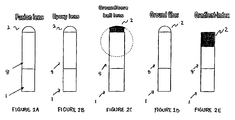
- Microlens 2 are provided which include the following optical properties:
- Figures 2A-E show microlenses 2 that can be manufactured efficiently according to the methods disclosed herein while achieving the parameters listed above.
- lenses 2 There are two basic types of lenses 2: (1) lenses 2 that use a radiused end ( Figures 2A-D) and (2) lens 2 that use a longitudinal or radially varying index (e.g., GRIN lenses) ( Figure 2E). Combinations of both types of lens may also be used.
- a single-mode optical fiber 1 typically consists of an 80 ⁇ m or 125 ⁇ m cladding and a 4 to 10 ⁇ m core as known in the art.
- the lens 2 typically cannot be directly affixed to the single-mode fiber 1 because it is necessary that an optical beam transmitted through the optical fiber 1 first expand to the required beam diameter prior to being focused by the lens 2 .
- the space between the lens 2 and the single-mode fiber 1 is filled by a coreless fiber 8 .
- the length of the coreless fiber 8 is calculated by selecting optical properties the user desires in the optical probe.
- a 29 ⁇ m spot size, and a 3 mm working distance would require ⁇ 810 um of coreless fiber 8 followed by a lens 2 with a spherical surface having a radius of curvature of ⁇ 225 ⁇ m.
- Figure 3 shows the relationship between the beam spot size and the lens 2 radius of curvature for a coreless fiber 8 having a length of ⁇ 810 um and lenses 2 with varying radii of curvature.
- the design of the lens 2 system can be accomplished with knowledge of Gaussian beam propagation which is well detailed in many standard textbooks.
- the equations as applied to the newly disclosed microlenses 2 are outlined below.
- ⁇ ( z ) ⁇ 0 1+ z z 0 2
- ⁇ (z) the beam radius at location z
- z 0 the Rayleigh range and is the distance at which the peak intensity falls to 1 ⁇ 2 of its value as measured at the beam waist.
- the Rayleigh range is given by ⁇ 0 2 / ⁇ , where ⁇ is the wavelength of the light in a vacuum, and ⁇ is the index-of-refraction of the medium.
- the Rayleigh range thus dictates the depth of field of the lens 2 , which is typically defined as twice z 0 and is often called the confocal parameter. As shown in Figures 1 and 4, the distance from the waist location of the imaged beam back to the lens 2 surface is defined here as the working distance of the lens 2 .
- the desired working distances (z) and depth of fields (z o ) are comparable and classical optics cannot be used effectively.
- a desired working distance and depth of field for lens 2 are chosen. These parameters determine the required beam waist size to be created by the lens 2 .
- the required waist size and desired location of the beam waist in space in turn determine the required beam size, as well as the phase front radius of curvature (of the outgoing beam) at the lens 2 surface.
- the coreless fiber 8 between the single-mode fiber 1 and the lens 2 must allow the beam to expand from the exit of the single-mode fiber 1 to match the beam size required at the surface of the lens 2 .
- the lens 2 must also bend the phase front of the incoming beam from the sample to match that of the outgoing beam transmitted through the single-mode fiber 1.
- the coreless fiber 8 and the lens 2 radius of curvature are uniquely determined given two input requirements (and given the single-mode fiber geometry and wavelength) - working distance and depth of field.
- Equation 1 Using Equations 1 and 2 above, and assuming that the radial distances are small when compared to the longitudinal distances (the well-known paraxial approximation, a valid assumption for long-working-distance lens 2 designs as described herein), a simple relationship can be derived for the required radius of curvature: where R lens is the radius of curvature of the lens 2 surface, n 1 is the index of the coreless fiber 8, n 0 is the index of the medium (nominally air or saline) in which the new waist is formed, and R i and R f are the curvatures of incoming and outgoing Gaussian beams, respectively.
- the required length of the coreless fiber 8 can be easily calculated using Equation 1 .
- the appropriate radius of curvature of a lens 2 required to achieve the properties of large working distance and depth of field and small beam spot size may be determined.
- Figure 3 is a graph showing the relationship between the beam spot size and the location of the beam waist for lenses 2 having a variety of curvatures calculated in this manner. It can be seen that a lenses 2 with a steep curvature (small radius of curvature) produces the smallest beam waist at the shortest distance as expected. Note that these equations are approximate and that more detailed and precise analysis can be preformed using commercially available physical optics design packages. These include, but are not limited to, CODE V (Optical Research Associates, Pasadena, California), OSLO (Sinclair Optics, Inc., Fairport, New York) and GLAD (Fraunhofer IAO, Stuttgart, Germany) commercial optical beam and design packages.
- Figure 4 is a schematic showing the properties of an optical beam obtained from an optical probe which includes the microlens 2 discussed above.
- a single-mode fiber 1 is spliced or otherwise secured to the lens 2.
- the lens 2 is approximately the same diameter as the single-mode optical fiber 1 .
- the optical fiber 1 may include a variety of thin coatings to ruggedize it which can be commercially purchased from Corning® (Coming Incorporated, Coming, New York), Spectran® (Spectran, Sturbridge, Massachusetts), and other commercial fiber optic companies.
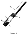
- a 90 degree (or other suitable angle) fold mirror 3 is affixed to the lens 2 also using splicing or.glue. The fold mirror 3 is coated with a high reflectance material or operates in total internal reflection.
- the fold mirror 3 is made of metal and is located separately from the lens (e.g., as shown in Figure 5). In another embodiment of the invention, the fold mirror 3 is made by polishing another section of coreless fiber on a 45 degree (or other angle for forward or backward scanning) which is then metal- or dielectric-coated. In a further embodiment of the invention, the fold mirror 3 has a dichroic coating to allow one wavelength to reflect and one wavelength to simultaneously transmit through the mirror 3.
- fold mirrors 3 are described in examples throughout the specification, any type of optical element which can steer a light beam and serve as a beam director 3 is encompassed within the scope of the invention.
- beam director and “fold mirror” 3 are used interchangeably herein.
- the design of the microlenses 2 of the present invention minimizes the beam spot size at the working distance of the lens 2 and creates a nearly flat phase front of the beam at this location, i.e., forming a beam waist at a spot located at the working distance of the lens.
- the equations disclosed above predict a working distance (defined here as the beam waist distance as measured from the apex of the lens 2 ) of 3mm for a lens 810 ⁇ m in length, with a radius of 225 ⁇ m, an operating wavelength of 1.32 ⁇ m, and a material index of refraction of 1.45.
- coreless fiber 8 region is directly attached to a single-mode fiber 1.
- an optical beam transmitted through the single-mode optical fiber 1 can gracefully expand to the required diameter of the lens 2 prior to focusing by the lens 2.
- the coreless fiber 8 can have the same diameter as the single-mode fiber 1 cladding and can be directly fusion-spliced using standard fusion splicer equipment, such as an Ericcson Fusion Splicer (Amherst Instruments, Amherst Fiber Optics, Brentwood, Tennessee), ensuring low loss, solid adhesion, and preservation of the single-mode Gaussian beam characteristics.
- the coreless fiber 8 is index-matched to the single-mode fiber 1 to ensure minimum back-reflection and loss.
- the optic fiber 1 -lens 2 assemblies in Figure 2A-D use lenses 2 with curved surfaces.
- the length of the coreless fiber 8 region and radius of curvature of the lenses 2 are chosen to obtain the required beam parameters (i.e., beam spot size, depth of field, and working distance) such as those shown in Figure. 1 and described previously.
- a number of methods of manufacturing the required lenses 2 are encompassed within the scope of the invention. These include using heat from a fusion splicer to melt the end of a coreless fiber 8 where surface terision will create a nearly circularly symmetrical lens 2 (Figure 2A).
- the fusion time and fusion current (heat) of the fusion splicer are adjusted and the manufacturer manipulates the end of the coreless fiber 8 relative to the fusion arc produced by the fusion splicer.
- heat fusion current
- a small drop of UV or other suitable glue can be placed using a micropipette and cured on the end of the coreless fiber 8 .
- a volume of glue and a type of glue with the proper surface tension and viscosity so that upon placing the glue on the end of the coreless fiber 8, surface tension and viscosity cause the glue to "ball-up" with the desired surface profile and radius.
- the radius of curvature will approximately equal the radius of the coreless fiber 8 (and therefore, also the radius of the single-mode fiber 1 ).
- the radius can be increased to approximately 5 to 10 times the radius of the coreless fiber 8.
- the radius of curvature of the lens 2 can further be slightly modified by locating the coreless fiber 8 vertically, with gravity pulling the glue down, to flatten the radius of curvature.
- the coreless fiber 8 is held upside down to slightly increase the radius of curvature.
- the amount of glue can be controlled using a micropipette or by sequentially transferring a large ball of glue from the end of one fiber to a coreless fiber 8 without any glue.
- the volume of the glue will tend to decrease by a factor of two for each transference. Other methods known by those skilled in the art can be used to setting the proper volume of glue to be placed on the end of the coreless fiber 8 and cured.
- ball lenses (with appropriate shaping) 2 can also be shaped to a diameter nearly equal to the single-mode optical fiber 1 diameter and secured to the end of the coreless fiber 8 using UV or another suitable glue as shown in Figure 2C. This can be accomplished by polishing the ball lenses 2 to form small, thin hemispheres or by coring the ball lenses 2 to form rod lenses 2.
- the end of the coreless fiber 8 distal to the single-mode fiber 1 can be mechanically ground using grinding and polishing techniques known in the art.
- the end of the coreless fiber 8 forms the lens 2 as shown in Figure 2D.
- the coreless fiber 8 is made to have the same index of refraction as the lens 2 to minimize loss and back-reflections of the optical beam transmitted from the single-mode fiber 1 .
- the coreless fiber 8 and lens 2 are one integral unit.
- Radiused lenses 2 may be manufactured using reflow technology whereby a material (e.g., polymethyl methacrylate (PMMA)) is deposited on the end of the coreless fiber 8 and heated so that material reflows to form a nearly circularly symmetrical lens 2.
- a material e.g., polymethyl methacrylate (PMMA)
- PMMA polymethyl methacrylate
- the radiused microlenses 2 of Figures 2A-D, as well as the flat lens 2 shown in Figure 2E, can be affixed to an external fold mirror 3, as shown in Figure 5.
- the fold mirror 3 is metered (or registered) with respect to a lens 2 using a clear plastic or glass metering tubing or cover 9 of optical quality. Other types of metering are possible and encompassed within the scope of the invention.
- a metal or non-optically transparent media is used and a small hole is cut or placed at an appropriate location with respect to the fold mirror 3.
- the diameter of the metering tubing 9 (and thus the total outer diameter of the lens 2 /beam director 3 assembly) can easily be made to less than 250 ⁇ m.
- This cylindrical lens effect may be compounded when the ultra-small optical probe is placed in saline or in another environment such as blood.
- the cylindrical surface of the tubing 9 (combined with the index of the sample medium) may act as a cylindrical lens more powerful than microlens 2 and can become a major detriment to the imaging quality of the system.
- the present invention provides methods to circumvent this effect.
- a plastic metering tubing 9 is used and a flat spot 9fs is created in the tubing 9 by heat-treating the tubing 9.
- the tubing 9 material it is possible to index-match the tubing 9 material to the sample medium.
- the tubing 9 is made with a similar index of refraction, i.e., ⁇ 1.3.
- An optical transmitter is placed between the lens 2 and the fold mirror 3 which also has a similar index of refraction of ⁇ 1.3.
- index-matching the lens 2 it is important to use a lens 2 that has a radiused end to take into account differences between the refractive indices of the sample medium, the optical transmitter and the lens 2.
- Lenses 2 that have an aspheric surface are also within the scope of the invention.
- the metering tubing 9 is made from commercially available square tubing (plastic or glass). Square tubing can also be made in several ways, such as by heat shrinking over a square metal wire or glass fiber, by extruding the tubing square, or by blow molding the tubing.
- the last lens 2 shown in Figure 2E is the embodiment according to the invention.
- This lens 2 can be made in several ways.
- a lens 2 having a graded index of refraction is used.
- radial (or longitudinal) variation in the index of refraction of the GRIN lens 2 causes the phase front of the light beam transmitted through the optical fiber 1 to be bent in a way which is analogous to the phase bending obtained from a conventional curved-surface lens.
- Materials for such lens 2 are commercially available and are known in the art as GRIN materials.
- the center index of the lens 2 would be made to match the single-mode fiber 1 core (or the coreless fiber 8 ) index.
- Multimode lenses with graded index profiles are made by using an industry-standard SMF-28 single-mode fiber 1 as the primary light guide, attaching ⁇ 750 ⁇ m of coreless fiber 8 (for beam expansion), and then attaching ⁇ 100 ⁇ m of multimode fiber ( ⁇ of 1.8, A of 0.038) to the coreless fiber 8.
- the multimode fiber then serves as the lens 2 .
- the multimode fiber is precision cleaved at a predetermined position based on calculations described above to achieve a desired working distance and depth of field.
- a graded index lens 2 made by the disclosed method can achieve a beam waist radius size of ⁇ 30 ⁇ m and a beam waist location of nearly 2 mm from the fiber tip of the optical probe (i.e., the distal end of the GRIN lens).
- the lens 2 has a very high Gaussian beam quality, where quality is defined as the deviation of the measured beam intensity profile from the ideal Gaussian profile. Beam quality is important, both for image quality considerations, and for light recoupling efficiency considerations.
- the multimode fiber forming the lens 2 can be similar to standard Spectran® 62.5/125 multimode fiber. However, it is also desirable to have a larger ratio of core to cladding.
- fiber similar to 62.5/125 multimode fiber is ordered from commercial sources (e.g., Lucent® Technologies, Murray Hill, New Jersey; SpecTran Specialty Optics, Avon, Connecticut) and the fiber is drawn to the size of 105/125 multimode fiber. The graded index profile is then simply scaled down from 62.5 to 105 ⁇ m in diameter.
- the coreless fiber 8 can be eliminated if the gradient coefficient is reduced enough to allow the beam to expand to its required diameter while traversing the GRIN lens 2 .
- Commercially available multimode fiber as well as GRIN lens known in the art have a gradient coefficient that is too strong (i.e., an A coefficient that is too large) for the designs presented here.
- the present invention provides methods to achieve customized gradients.
- the standard ABCD matrix formalism for treating Gaussian beam propagation in the paraxial approximation can be used.
- the ABCD matrix describing the propagation from a single-mode fiber 1 through a GRIN material and into the medium interface is given by: where A' is ( ⁇ A)/a, and n smf is the index of the single-mode fiber 1 .
- the ABCD law for the transformation of Gaussian beams can be used to solve for the A' parameter given the other material parameters and, as before, the desired depth of field and working distance.
- Elimination of the coreless fiber 8 region results in a significant savings in the complexity of the lens 2 system as the number of fusion splices and precision cuts is reduced two-fold.
- Another advantage of customizing the GRIN material is that the effects of the fold mirror 3 (i.e., the impact of additional optical length and material indices) can be incorporated into the algebraic equations discussed above and/or into physical models so that the A coefficient can be optimized for the complete system including beam director/fold mirror 3 .
- lens 2 system in Figure 2E over the radiused lenses 2 shown in Figures 2A-2D is that an optical probe comprising this type of lens 2 can be immersed in saline or in another environment (e.g., blood or tissue) with an refractive index not equal to 1 and can still be used to image.
- an optical probe comprising this type of lens 2 can be immersed in saline or in another environment (e.g., blood or tissue) with an refractive index not equal to 1 and can still be used to image.
- GRIN materials perform the phase bending within the GRIN medium itself.
- an integral fold mirror 3 can be directly attached to the lens 2 .
- the fold mirror 3 is be made by purchasing "D-core” fiber (i.e., a fiber formed in the shape of the letter "D") or square fiber (such as obtained from Lucent Technologies, Murray Hill, New Jersey, SpecTran Specialty Optics, Avon, Connecticut) or by polishing a fiber to have a flat facet along its length to create the desired D-shape.
- the D-fiber is then spliced onto a GRIN/multimode fiber lens 2 and the end is polished on a 45 degree angle (or other suitable angle for forward or reverse imaging) to reflect the outgoing beam from the single-mode optical fiber 1 through the flat of the D (thus avoiding parasitic cylindrical lens effects).
- the mirror 3 can then be either metal -or dielectric-coated or, as mentioned above, can be coated with a dichroic beam splitter to allow simultaneous forward and side imaging via different wavelengths.
- the angle of the fold mirror 3 is greater or less than the angle for total internal reflection of the fold mirror 3 , as given by Snell's law ( ⁇ 45 degrees in silica/air interface), then it is not necessary to coat the mirror 3.
- the total diameter of the optical lens 2 /fold mirror 3 in Figure 6 can easily be made less than 250 ⁇ m while obtaining the desired beam parameters (e.g., as shown in Figure 1). Further, the lens 2 can be made using standard fusion splicing and polishing techniques, and thus can be low cost, with minimal back-reflections and maximal performance. It is also possible to make the integral fold mirror 3 of Figure 6 by first fusion splicing a short section of coreless fiber 8 to the GRIN lens 2 , then polishing the edge of fold mirror 3 flat or on a slight angle. In a further embodiment of the invention, it is possible to make a section of a coreless fiber 8 square-shaped or D-shaped during the fiber draw to form the fold mirror 3 . The fold mirror 3 can also be made using polishing, cleaving, or sawing techniques.
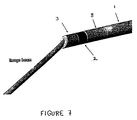
- a section of a coreless fiber is optically coupled to the lens 2 and is placed between the lens 2 and the sample to act as a beam director 3 .
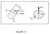
- the beam director 3 is polished on an angle to yield a prism effect. If the beam director 3 is then spun circumferentially, the beam transmitted through the single-mode optical fiber 1 will sweep out, or scan, a conical section. Such a scan can be useful for applications where the probe is adapted for use as an insertional medical device, such as a small guidewire, catheter, endoscope, bronchoscope, needle, or trocar.
- the invention provides ultra-small optical probes which can be used to measure the optical properties of a test sample in situ.
- the ultra-small optical probe is coupled to an optical system 16 and the probe is placed in proximity to a test sample (in this embodiment, a blood vessel 17 ).
- An optical beam is transmitted from the probe to the sample in situ ; and light transmitted from the sample is detected.
- the term "in situ” means without removing the sample from its natural location and includes imaging internal vessels, spaces, or channels inside the body of a human being.
- test sample is used to refer to any sample for which measurements of optical properties are desired. The term "test” does not imply that the sample relates to a pathological condition or even that the optical properties of the sample are unknown; however, the probes and methods of the present invention may be used to diagnose and intervene in pathological conditions.
- the application also relates to connectors 12 and 15 which connect the ultra-small optical probes to optical beam delivery and imaging systems 16.
- the connectors allow the user to quickly connect and disconnect a probe from an optical imaging system 16 , and in particular, from a driving mechanism which drives the optical probe to perform scanning of a sample.
- the ultra-small optical probe comprises a housing 11 which is in the form of an insertional medical device and is used to image narrow, tortuous lumens or small spaces in situ within the body of an organism.
- ultra-small optical probes disclosed herein can be used to measure the optical properties of a variety of spaces (e.g., imaging channels or spaces in articles of manufacture) and that such applications are also encompassed within the scope of the present invention.
- the ultra-small optical probe comprises a probe housing 11 which is in the form of an insertional medical device.
- Figure 8 shows an embodiment of the invention in which the probe housing 11 is a guidewire.
- Other types of insertional medical devices are also contemplated, and are encompassed within the scope of the invention. These include, but are not limited to, , bronchoscopes, needles, endoscopes and trocars.
- the guidewires of the present invention may also be used as components of other insertional medical devices (e.g., adapted for fitting into the guidewire lumen of a catheter).
- Guidewire housing 11 materials include, but are not limited to, metal, plastic, hypotubes, and the like.
- the miniature optical fiber 1 /optics lens 2 /beam director 3 assembly of the ultra-small optical probe is housed inside a small guidewire housing 11 (typically ⁇ 0.018" in diameter).
- an OCT or other optical imaging or beam delivery system e.g., a photodynamic therapy system or fluorescence system
- the RFOJ 13 is used to circumferentially spin or rotate a single-mode fiber 1 or a miniature torque fiber within the probe housing 11.
- This device can be similar to the one described in U.S.S.N: 08/607,787, filed 2/27/96, the entire disclosure of which is herein incorporated by reference.
- Single-mode fibers 1 used in this embodiment of the invention are those known in the art and typically consist of a ⁇ 4-10 ⁇ m core, a 80-125 ⁇ m cladding, and a 250-900 ⁇ m protective buffer.
- the protective buffer can be removed.
- the protective buffer can be replaced with a relatively thin (1 ⁇ m to 50 ⁇ m), high strength, low friction coating to fit within the small opening defined by of the optical probe housing 11 .
- Such high strength coatings can be obtained from commercial fiber houses such as Corning® and Spectran®.
- the single-mode fiber 1 can be directly torqued to perform rotational scanning or a miniature torque cable can be added to aid in torching the fiber 1 . It is important that the internal diameter of the guidewire housing 11 be made to have minimal friction and burrs.
- the output of the RFOJ 13 is connected to a disposable connector 12 that consists of an FC/APC male to female connector with minimal loss and back-reflections.
- disposable connector 12 is used to cross the sterile/non-sterile boundary 14 .
- the RFOJ 13 , as well as the connector 12 are housed in a disposable sterile bag to allow repeated use of the RFOJ 13 by eliminating contaminants.
- the bag covers the RFOJ 13 and associated proximal coupling hardware to prevent any patient or sample bodily contaminants from touching the hardware. Thus, after a patient exam the bag can be removed and thrown away without the need to sterilize the RFOJ 13 and proximal coupling hardware.
- Such bags are standard in intravascular ultrasound devices and are required in such medical procedures by the Food and Drug Administration.
- the output of the disposable connector 12 is connected to a quick disconnect unit 15 .
- the purpose of the quick disconnect unit 15 is to allow the physician/user to quickly disconnect both the guidewire housing 11 and another insertional or interventional medical instrument to which the guidewire housing 11 is coupled from the disposable connector 12 and RFOJ 13.
- the other insertional/interventional medical device is then passed over the guidewire housing 11 for interchange with still other devices or for manipulation by the physician/user.
- Insertional/interventional medical devices to which the guidewire housing 11 may be coupled include, but are not limited to, a pass or exchange catheter, a balloon angioplasty device, a stent delivery device, an artherectomy catheter, and a drug delivery device.
- the physician is viewing an arterial lesion in a blood vessel 17 that he/she determines will require an interventional procedure, he/she quickly disconnects the guidewire housing 11 from the RFOJ 13 via the quick disconnect unit 15 (shown in Figures 8 and 9), slides a suitable interventional device over the guidewire, reconnects the housing 11 to the RFOJ 13 , and begins imaging using imaging system 16 .
- imaging system 16 physician/user can easily see when the interventional device is over the lesion. By being able to watch the placement of the interventional device during the interventional procedure the physician/user can inspect the lesion after the interventional device is removed.
- the physician uses the guidewire probe and the interventional device in an atherectomy procedure (or other surgical cutting procedure) where the optical probe allows the physician/user to determine where to cut.
- the interventional device used in conjunction with the guidewire probe is a drug delivery device where the image produced on a display screen of the optical system 16 allows the physician/user to determine how much of a drug to inject per unit time.
- the optical imaging system 16 used is an OCT system and the interventional device used is a stent. In this embodiment of the invention, the length and type of stent is determined before the procedure and the amount of inflation of the stent is controlled as the stent is being deployed, using information obtained from the optical probe and imaging system 16 .
- the diameter of that portion of the quick disconnect unit 15 which is adjacent to a first end of the guidewire housing 11 not exceed the maximum diameter of the guidewire housing 11 (e.g., 0.014 inches) to allow the easy exchange of other insertional/interventional devices over the guidewire housing 11.
- Figures 9A-C show the mechanical design of the quick disconnect unit 15 according to one embodiment of the invention.
- a single-mode fiber 1 which is polished (or cleaved) at one end is contained within ferules 18 having a 0.014" outside diameter ( Figure 9A).
- the ferules 18 are generally tubular structures which can be made from a wide variety of materials including, but not limited to, ceramic, glass, metal and plastic.
- the ferules 18 are precision-manufactured to tight tolerances both diametrically and between the inside and outside diameters of the ferules 18 and the single-mode optical fiber 1 /lens 2 /mirror 3, to ensure proper alignment between these optical elements.
- the tolerance is less than 1 ⁇ m.
- the tolerance is less than 1 ⁇ m.
- the ferule 18 is also keyed and angle-polished (as is done with commercial FC/APC connectors) to minimize back-reflections.
- the polished single-mode optical fiber 1 /lens 2 /mirror 3 /ferule 18 assembly is then fit within a ferule collar 19 ( Figure 9B).
- the ferule collar 19 is slit radially (the slit not visible on this scale drawing) to the center to facilitate side loading of the single-mode optical fiber 1 /lens 2 /mirror 3 /ferule 18 assembly into the housing 23 of the quick disconnect unit 15. Slitting the components radially allows the single-mode optical fiber 1 /lens 2 /mirror 3 /ferule 18 assembly to be quickly removed from the quick disconnect unit 15 to facilitate passage of an insertional/interventional medical device over the probe housing 11 .
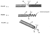
- an elastomeric spring 22 is provided at the end of the ferule collar 18 closest to the housing 23 of the quick disconnect unit 15.
- the single-mode optical fiber 1 /lens 2 /mirror 3 /ferule 18 assembly is set within an endcap 20 which is also radially slit (slit not visible in Figure 10B) to the center.
- the endcap 20 is screwed into a split sleeve 21 contained within the housing 23 of the quick disconnect unit until it can no longer be turned.
- the ferules 18 are being pressed into the split sleeve 21 .
- the split sleeve 21 is cut axially to allow for radial expansion. It is manufactured with a precision inside diameter that is slightly smaller than that of the ferules 18 .
- the split sleeve 21 is contained sufficiently loosely within the housing 23 of the quick disconnect unit 15 allowing it to self-center itself. Interference created between the inside diameter of the split sleeve 21 and the outside diameter of the ferules 18 is used to align the ferules 18 radially and to maintain concentricity with the split sleeve 21 , the end cap 20 , and the ferule collar 19 .
- an elastomeric spring 22 is provided in proximity to the ferule collar 19 , fully engaging the endcap 20 compresses the elastomeric spring 22 , applying an axial load that forces the ferules 18 containing the optical fiber 1 and the split sleeve 21 together.
- the elastomeric spring 22 is split radially to the center. The axial force created by the compressed spring 22 and the precision radial alignment between the ferules 18 and split sleeve 21 creates a reliable optical connection between the optical elements of the ultra-small probe.
- the probe housing 11 together with the portion of the connector device proximal to the probe housing 11 is not substantially greater in diameter than the outer diameter of a standard guidewire so that a physician/user can quickly disconnect the optical probe from the RFOJ 13 and exchange other medical devices over the probe housing 11 and connector elements.
- the split sleeve 21 and the housing 23 of the quick disconnect unit 15 are designed so that the distal side of the quick disconnect 15 (away from the optical imaging system 16) includes a 0.014 inch ferule 18, but the proximal side has a much larger ferule 18 (e.g., > 1 mm). In this configuration, the quick disconnect unit 15 is compatible with standard commercially available fiber optical connectors.
- the RFOJ 13 is also coupled to a longitudinal translation/pull back device 25 as shown in Figure 8.
- the purpose of the pull back device 25 is to permit longitudinal scanning of the lens 2 /beam director 3 of the optical probe/guidewire. This can be accomplished by actuating the pull back mechanism 25 to move one of the guidewire housing 11 and the optical fiber 1 along a longitudinal axis of the optical fiber. Movement is effected by pulling back a mechanical linkage 26 which is coupled to the guidewire housing 11 and the RFOJ 13 as shown in Figure 8.
- the linkage 26 can be made by several methods as known by those skilled in the art, such as by using linear stepper stages or coil winding technology.
- the ferules 18 and guidewire housing 11 are mechanically linked using standard techniques for affixing rotary joints as known in the art.
- the optical fiber 1 is pulled back within the housing 11 of the guidewire.
- the quick disconnect unit 15 is modified to allow relative longitudinal motion between the single-mode optical fiber 1 and the guidewire housing 11 .
- the entire optical probe/guidewire may be pulled back. This prevents the guidewire from damaging a vessel 17 and allows easy repositioning of the optical probe/guidewire after pull back.
- the optical probe/guidewire/catheter/optical system may be used as a diagnostic catheter, mapping out potential areas of intervention for a cardiologist, for example.
- the RFOJ 13 is eliminated in favor of a high-speed longitudinal scanning mechanism, such as a galvanometer driven translation mechanism.
- This type of scanning mechanism uses a Galvonometer motor coupled to a linear ball-bearing slide which is in turn coupled to the optical fiber 1.
- the slide is coupled to the motor using a flexure that translates the rotational motion of the galvonometer into linear translation of the slide and optical fiber 1.
- the high-speed scanning mechanism is used to "push-pull" the fiber back and forth at high speed past a transparent section in the probe housing 11 (e.g., a window 24 ).
- a galvanometer driven translation mechanism may be obtained from commercial sources (e.g., General Scanning, Incorporated, Watertown, Massachussetts).
- the quick disconnect unit 15 and the disposable connector 12 are separable elements, while in another embodiment of the invention the quick disconnect unit 15 and disposable connector 12 are part of a single connector device.
- the output of the RFOJ 13 also has ferules 18 which are the same size as that of the quick disconnect 15 and directly connects to the quick disconnect housing 23 so that the disposable connector 12 and quick disconnect 15 are thereby integrated into one assembly.
- a guidewire housing 11 is shown in more detail in Figure 10.
- the proximal end of the housing 11 mates with the quick disconnect unit 15.
- the optical fiber 1 is free to spin relative to the housing 11 but is fixed longitudinally so that the quick disconnect ferule 18 and housing 11 cannot be separated.
- the combination of circumferential scanning from the spinning fiber 1 within the guidewire housing 11 , and longitudinal scanning when the pull back mechanism 25 is used, allows a three-dimensional profile of a vessel 17 to be collected.
- an image can be displayed and manipulated to allow the physician/user to view the vessel 17 on the imaging system's display monitor.
- the probe housing 11 is fabricated so as to transmit light from the single-mode optical fiber 1 through at least a section of the housing 11 to the sample. Similarly, light retroreflected from the sample also passes through at least a section of the housing 11 back to the single-mode optical fiber 1.
- a section of the housing 11 is at least partially transparent.
- the housing 11 includes an opening 24, such as a window, which is in optical communication with the lens 2 and beam director 3.
- the opening/window 24 is secured in the housing 11 wall to allow the lens 2 /beam director 3 to image through the guidewire housing 11 and onto the sample (e.g., a blood vessel 17 wall).
- the beam director 3 is in proximity to a section of the housing 11 which is at least partially transparent, e.g., the opening/window 24 .
- the housing 11 itself is made of plastic or another suitable material that may be transparent to optical radiation. In this embodiment of the invention, no opening or window 24 is needed.
- the housing 11 may comprise a hole (e.g., a slot, a notch, a port, a cutout), or a plurality of holes, through which the beam from the single-mode optical fiber 1 may be directed for scanning of the sample.
- a hole e.g., a slot, a notch, a port, a cutout
- an "opening" may be uncovered and completely open or may be covered by a transparent material.
- the design of the opening/window 24 (in Figures 8, 10, and 11A-C) is an important part of the overall optical probe design.
- the window 24 allows light from an optical fiber 1 to be transmitted through the housing wall 11 .
- suitable window 24 materials into the housing 11 .
- Windows 24 that are formed into transparent tubes that exhibit the same or similar outside diameter and shape as the primary housing 11 are greatly preferred since they are easiest to join to the housing 11 . This ensures that the completed assembly does not exhibit any sharp edges or discontinuities, a critical consideration in medical applications.
- Flat window 24 materials can be used, as discussed above with respect to the metering tubing 9 . While flat window 24 materials make the optical imaging properties of the probe easier to deal with, flat windows cannot be made to accommodate 360 degree scanning and therefore cannot be used when a circumferential scanning guidewire optical probe is desired.
- n 1 is the medium index to the left of the window 24
- n 2 is the index of the window 24 material itself
- n 3 is the index in the medium to the right of the window 24
- R 1 is the inner radius of curvature
- R 2 is the outer radius
- t is the window 24 thickness.
- the above equation is for a window with a spherical surface, whereas when using the circular/cylindrical windows of the present invention, the effect is only in the direction parallel to the housing 11 axis.
- the above equation serves to illustrate the importance of matching the index of refraction of the window 24 with that of the medium to obtain better image quality.
- a flat window 24 (i.e. driving the radii towards ⁇ ) will also minimize detrimental effects on imaging.
- a window 24 section is made in a square or hexagonal form to allow radial scanning of a sample.
- a scan correction algorithm is programmed into a processor which is part of the optical system 16.
- circular windows are preferred.
- Window 24 materials which posses desired qualities (index, material strength, optical transmission, material optical quality, sterilizability, and so forth) include, but are not limited to, fluoropolymers, other plastics, glass, and the like.
- a series of small holes are provided in the proximal section of the housing 11 wall to allow the outside sample medium (e.g., water or saline) to fill any interstitial gaps between the lens 2 , beam director 3 , and the inner radius of the window 24 , to further aid in index-matching and to reduce unwanted Fresnel reflections.
- the space between the lens 2 and the window 24 is filled and sealed with an optical transmitter including a gel, an oil, or other suitable materials, to perform the desired refraction index matching.
- n 2 - n 1 R 1 n 2 - n 3 R 2
- n 1 is the index of the matching fluid or gel
- n 2 is the index of the window 24 material
- n 3 is the index of refraction of the surrounding sample medium.
- the index-matching material is placed in the optical probe/guidewire just prior to patient use.
- Gaussian beam modeling as previously described, can be employed to more accurately assess the effect of a curved window 24 on image quality, allowing engineering design decisions to be made when choosing materials and shapes.
- the larger the fraction of holes in the housing 11 wall e.g., a hypotube), the larger the fraction scan area.
- the number of holes in the housing 11 is optimized to maximize image quality while maintaining structural integrity.
- the probe housing 11 may further comprise elements found in standard guidewires.
- a spring 25 is affixed to the opening/window 24 of the guidewire housing 11 .
- the spring 25 allows the optical probe/guidewire flexibility in navigating tortuous pathways in the body.
- the spring 25 is configured so as not to cover at least a section of the housing 11 which includes the opening/window 24.
- the opening 24 comprises a clear section of hypotube and two sets of springs 25 are provided; each set stopping short of the opening 24 /hypotube.
- a flat safety ribbon is used to ensure that both ends of the spring coil 25 remain attached.
- the spring 25 can be continually wound to be one unit.
- the opening 24 /hypotube is affixed to both ends of the spring with an adhesive or by mechanical means. Safety ribbons can also be used.
- the spring 25 includes a radio-opaque tip 28 .
- the entire spring 25 comprises radio-opaque material.
- a mechanism to flush sample medium (e.g., blood) from the optical probe/guidewire is provided in order to improve the penetration depth of the image.
- flushing is done automatically using the optical system 16 (e.g., an OCT system) or manually, using standard flushing catheters passed over, or adjacent to, the guidewire housing 11 .
Applications Claiming Priority (3)
| Application Number | Priority Date | Filing Date | Title |
|---|---|---|---|
| US370756 | 1999-08-09 | ||
| US09/370,756 US6445939B1 (en) | 1999-08-09 | 1999-08-09 | Ultra-small optical probes, imaging optics, and methods for using same |
| PCT/US2000/040599 WO2001011409A2 (en) | 1999-08-09 | 2000-08-08 | Ultra-small optical fiber probes and imaging optics |
Publications (2)
| Publication Number | Publication Date |
|---|---|
| EP1222486A2 EP1222486A2 (en) | 2002-07-17 |
| EP1222486B1 true EP1222486B1 (en) | 2005-11-09 |
Family
ID=23461028
Family Applications (1)
| Application Number | Title | Priority Date | Filing Date |
|---|---|---|---|
| EP00967374A Expired - Lifetime EP1222486B1 (en) | 1999-08-09 | 2000-08-08 | Ultra-small optical fiber probes and imaging optics |
Country Status (5)
Cited By (1)
| Publication number | Priority date | Publication date | Assignee | Title |
|---|---|---|---|---|
| DE102007045570A1 (de) | 2007-09-24 | 2009-04-02 | Robert Bosch Gmbh | Sonde und Vorrichtung zum optischen Prüfen von Messobjekten |
Families Citing this family (569)
| Publication number | Priority date | Publication date | Assignee | Title |
|---|---|---|---|---|
| US5951480A (en) * | 1997-09-29 | 1999-09-14 | Boston Scientific Corporation | Ultrasound imaging guidewire with static central core and tip |
| US6299622B1 (en) | 1999-08-19 | 2001-10-09 | Fox Hollow Technologies, Inc. | Atherectomy catheter with aligned imager |
| US7708749B2 (en) | 2000-12-20 | 2010-05-04 | Fox Hollow Technologies, Inc. | Debulking catheters and methods |
| US8328829B2 (en) | 1999-08-19 | 2012-12-11 | Covidien Lp | High capacity debulking catheter with razor edge cutting window |
| US7713279B2 (en) | 2000-12-20 | 2010-05-11 | Fox Hollow Technologies, Inc. | Method and devices for cutting tissue |
| US7887556B2 (en) * | 2000-12-20 | 2011-02-15 | Fox Hollow Technologies, Inc. | Debulking catheters and methods |
| DE10029206A1 (de) * | 2000-06-20 | 2002-01-10 | Schleifring Und Appbau Gmbh | Vorrichtung zur Übertragung optischer Signale |
| AU2002230842A1 (en) | 2000-10-30 | 2002-05-15 | The General Hospital Corporation | Optical methods and systems for tissue analysis |
| US9295391B1 (en) * | 2000-11-10 | 2016-03-29 | The General Hospital Corporation | Spectrally encoded miniature endoscopic imaging probe |
| US7699790B2 (en) | 2000-12-20 | 2010-04-20 | Ev3, Inc. | Debulking catheters and methods |
| US7927784B2 (en) | 2000-12-20 | 2011-04-19 | Ev3 | Vascular lumen debulking catheters and methods |
| AU2002231074A1 (en) | 2000-12-20 | 2002-07-01 | Fox Hollow Technologies, Inc. | Debulking catheter |
| JP2002196181A (ja) * | 2000-12-25 | 2002-07-10 | Nippon Sheet Glass Co Ltd | レンズ機能付き光ファイバおよびその製造方法 |
| JP2002196182A (ja) * | 2000-12-27 | 2002-07-10 | Nippon Sheet Glass Co Ltd | 傾斜面を有する光学素子 |
| DE10105592A1 (de) | 2001-02-06 | 2002-08-08 | Achim Goepferich | Platzhalter zur Arzneistofffreigabe in der Stirnhöhle |
| US20020150333A1 (en) * | 2001-02-17 | 2002-10-17 | Reed William Alfred | Fiber devices using grin fiber lenses |
| US20020140942A1 (en) * | 2001-02-17 | 2002-10-03 | Fee Michale Sean | Acousto-optic monitoring and imaging in a depth sensitive manner |
| US6760112B2 (en) * | 2001-02-17 | 2004-07-06 | Lucent Technologies Inc. | Grin-fiber lens based optical endoscopes |
| US6542665B2 (en) | 2001-02-17 | 2003-04-01 | Lucent Technologies Inc. | GRIN fiber lenses |
| US6873768B2 (en) * | 2001-03-16 | 2005-03-29 | Jds Uniphase Corporation | Compact optical fiber coupler |
| US8046057B2 (en) * | 2001-04-11 | 2011-10-25 | Clarke Dana S | Tissue structure identification in advance of instrument |
| GB2408797B (en) | 2001-05-01 | 2006-09-20 | Gen Hospital Corp | Method and apparatus for determination of atherosclerotic plaque type by measurement of tissue optical properties |
| EP1260841B1 (en) * | 2001-05-19 | 2007-07-11 | Lucent Technologies Inc. | GRIN fiber lenses |
| US7329223B1 (en) * | 2001-05-31 | 2008-02-12 | Abbott Cardiovascular Systems Inc. | Catheter with optical fiber sensor |
| US7532920B1 (en) | 2001-05-31 | 2009-05-12 | Advanced Cardiovascular Systems, Inc. | Guidewire with optical fiber |
| JP2005521069A (ja) * | 2001-06-15 | 2005-07-14 | コーニング インコーポレイテッド | 熱形成レンズ付ファイバ |
| EP1454173B1 (en) * | 2001-11-15 | 2009-05-13 | Picometrix, LLC | Focusing fiber optic |
| US7736301B1 (en) * | 2001-12-18 | 2010-06-15 | Advanced Cardiovascular Systems, Inc. | Rotatable ferrules and interfaces for use with an optical guidewire |
| AU2002364069A1 (en) * | 2001-12-18 | 2003-06-30 | Advanced Cardiovascular Systems, Inc. | Optical guidewire having windows or apertures |
| US6974557B1 (en) * | 2001-12-18 | 2005-12-13 | Advanced Cardiovasculer Systems, Inc. | Methods for forming an optical window for an intracorporeal device and for joining parts |
| US6947787B2 (en) * | 2001-12-21 | 2005-09-20 | Advanced Cardiovascular Systems, Inc. | System and methods for imaging within a body lumen |
| US7355716B2 (en) | 2002-01-24 | 2008-04-08 | The General Hospital Corporation | Apparatus and method for ranging and noise reduction of low coherence interferometry LCI and optical coherence tomography OCT signals by parallel detection of spectral bands |
| US6904197B2 (en) * | 2002-03-04 | 2005-06-07 | Corning Incorporated | Beam bending apparatus and method of manufacture |
| US8614768B2 (en) | 2002-03-18 | 2013-12-24 | Raytheon Company | Miniaturized imaging device including GRIN lens optically coupled to SSID |
| US7062135B2 (en) | 2002-03-21 | 2006-06-13 | Corning Incorporated | Method for fabricating curved elements |
| FR2838200B1 (fr) * | 2002-04-08 | 2004-08-06 | Optogone Sa | Collimateur optique pour fibre monomode presentant une section de fibre a gradient d'indice, fibre monomode a coeur etendu et procede de fabrication correspondants |
| WO2004019089A2 (en) * | 2002-05-31 | 2004-03-04 | Corning Incorporated | Low macrobending loss optical fiber |
| RU2242710C2 (ru) * | 2002-06-07 | 2004-12-20 | Геликонов Григорий Валентинович | Способ получения изображения объекта, устройство для его осуществления и устройство доставки низкокогерентного оптического излучения |
| US7672713B2 (en) | 2002-06-19 | 2010-03-02 | Infraredx, Inc. | Multi-channel catheter tip |
| US6891984B2 (en) * | 2002-07-25 | 2005-05-10 | Lightlab Imaging, Llc | Scanning miniature optical probes with optical distortion correction and rotational control |
| US8317816B2 (en) * | 2002-09-30 | 2012-11-27 | Acclarent, Inc. | Balloon catheters and methods for treating paranasal sinuses |
| EP1551273A4 (en) * | 2002-10-18 | 2011-04-06 | Arieh Sher | ATHEREOMETRY SYSTEM WITH IMAGING GUIDE WIRE |
| US20040111032A1 (en) * | 2002-12-04 | 2004-06-10 | Jeff Korn | Optical coupler for rotating catheter |
| US7616321B2 (en) * | 2002-12-04 | 2009-11-10 | Infraredx, Inc. | Optical coupler for rotating catheter |
| US8054468B2 (en) | 2003-01-24 | 2011-11-08 | The General Hospital Corporation | Apparatus and method for ranging and noise reduction of low coherence interferometry LCI and optical coherence tomography OCT signals by parallel detection of spectral bands |
| US7474407B2 (en) * | 2003-02-20 | 2009-01-06 | Applied Science Innovations | Optical coherence tomography with 3d coherence scanning |
| JP4805142B2 (ja) | 2003-03-31 | 2011-11-02 | ザ ジェネラル ホスピタル コーポレイション | 光路長が変更された異なる角度の光の合成により光学的に干渉する断層撮影におけるスペックルの減少 |
| US20070293744A1 (en) * | 2003-04-16 | 2007-12-20 | Monfre Stephen L | Apparatus and method for easing use of a spectrophotometric based noninvasive analyzer |
| US8246640B2 (en) | 2003-04-22 | 2012-08-21 | Tyco Healthcare Group Lp | Methods and devices for cutting tissue at a vascular location |
| US7241286B2 (en) * | 2003-04-25 | 2007-07-10 | Lightlab Imaging, Llc | Flush catheter with flow directing sheath |
| US7376455B2 (en) * | 2003-05-22 | 2008-05-20 | Scimed Life Systems, Inc. | Systems and methods for dynamic optical imaging |
| EP2280260B1 (en) | 2003-06-06 | 2017-03-08 | The General Hospital Corporation | Process and apparatus for a wavelength tuned light source |
| AU2004285412A1 (en) | 2003-09-12 | 2005-05-12 | Minnow Medical, Llc | Selectable eccentric remodeling and/or ablation of atherosclerotic material |
| DE10343808B4 (de) | 2003-09-22 | 2017-06-01 | Siemens Healthcare Gmbh | Medizinisches Untersuchungs- und/oder Behandlungssystem |
| US7061618B2 (en) | 2003-10-17 | 2006-06-13 | Axsun Technologies, Inc. | Integrated spectroscopy system |
| EP1685366B1 (en) | 2003-10-27 | 2011-06-15 | The General Hospital Corporation | Method and apparatus for performing optical imaging using frequency-domain interferometry |
| DE10354496B4 (de) | 2003-11-21 | 2011-03-31 | Siemens Ag | Medizinisches Untersuchungs- und/oder Behandlungssystem |
| US20050165315A1 (en) * | 2004-01-27 | 2005-07-28 | Infraredx, Inc. | Side firing fiber optic array probe |
| DE102004008370B4 (de) * | 2004-02-20 | 2006-06-01 | Siemens Ag | Katheter zur Durchführung und Überwachung von Rotablation |
| DE102004008373B3 (de) * | 2004-02-20 | 2005-09-29 | Siemens Ag | Vorrichtung zum Durchführen und Überwachen der endovaskulären Brachytherapie |
| US7754291B2 (en) * | 2004-03-26 | 2010-07-13 | Auld Technologies Llc | Miniature emblems and method of making same |
| DE102004015642B3 (de) | 2004-03-31 | 2006-02-02 | Siemens Ag | Vorrichtung zur Beseitigung eines vollständigen Gefäßverschlusses mit OCT-Überwachung |
| DE102004015640B4 (de) * | 2004-03-31 | 2007-05-03 | Siemens Ag | Vorrichtung zum Durchführen einer "Cutting-Balloon"-Intervention mit OCT-Überwachung |
| US8747389B2 (en) | 2004-04-21 | 2014-06-10 | Acclarent, Inc. | Systems for treating disorders of the ear, nose and throat |
| US20060063973A1 (en) | 2004-04-21 | 2006-03-23 | Acclarent, Inc. | Methods and apparatus for treating disorders of the ear, nose and throat |
| US8894614B2 (en) | 2004-04-21 | 2014-11-25 | Acclarent, Inc. | Devices, systems and methods useable for treating frontal sinusitis |
| US10188413B1 (en) | 2004-04-21 | 2019-01-29 | Acclarent, Inc. | Deflectable guide catheters and related methods |
| US9101384B2 (en) | 2004-04-21 | 2015-08-11 | Acclarent, Inc. | Devices, systems and methods for diagnosing and treating sinusitis and other disorders of the ears, Nose and/or throat |
| US20190314620A1 (en) | 2004-04-21 | 2019-10-17 | Acclarent, Inc. | Apparatus and methods for dilating and modifying ostia of paranasal sinuses and other intranasal or paranasal structures |
| US20070208252A1 (en) | 2004-04-21 | 2007-09-06 | Acclarent, Inc. | Systems and methods for performing image guided procedures within the ear, nose, throat and paranasal sinuses |
| US8146400B2 (en) * | 2004-04-21 | 2012-04-03 | Acclarent, Inc. | Endoscopic methods and devices for transnasal procedures |
| US7361168B2 (en) | 2004-04-21 | 2008-04-22 | Acclarent, Inc. | Implantable device and methods for delivering drugs and other substances to treat sinusitis and other disorders |
| US7654997B2 (en) | 2004-04-21 | 2010-02-02 | Acclarent, Inc. | Devices, systems and methods for diagnosing and treating sinusitus and other disorders of the ears, nose and/or throat |
| US8932276B1 (en) | 2004-04-21 | 2015-01-13 | Acclarent, Inc. | Shapeable guide catheters and related methods |
| US20060004323A1 (en) | 2004-04-21 | 2006-01-05 | Exploramed Nc1, Inc. | Apparatus and methods for dilating and modifying ostia of paranasal sinuses and other intranasal or paranasal structures |
| US9399121B2 (en) | 2004-04-21 | 2016-07-26 | Acclarent, Inc. | Systems and methods for transnasal dilation of passageways in the ear, nose or throat |
| US7419497B2 (en) | 2004-04-21 | 2008-09-02 | Acclarent, Inc. | Methods for treating ethmoid disease |
| US7462175B2 (en) | 2004-04-21 | 2008-12-09 | Acclarent, Inc. | Devices, systems and methods for treating disorders of the ear, nose and throat |
| US20070167682A1 (en) | 2004-04-21 | 2007-07-19 | Acclarent, Inc. | Endoscopic methods and devices for transnasal procedures |
| US7803150B2 (en) | 2004-04-21 | 2010-09-28 | Acclarent, Inc. | Devices, systems and methods useable for treating sinusitis |
| US8864787B2 (en) | 2004-04-21 | 2014-10-21 | Acclarent, Inc. | Ethmoidotomy system and implantable spacer devices having therapeutic substance delivery capability for treatment of paranasal sinusitis |
| US9554691B2 (en) | 2004-04-21 | 2017-01-31 | Acclarent, Inc. | Endoscopic methods and devices for transnasal procedures |
| US8702626B1 (en) | 2004-04-21 | 2014-04-22 | Acclarent, Inc. | Guidewires for performing image guided procedures |
| US9089258B2 (en) | 2004-04-21 | 2015-07-28 | Acclarent, Inc. | Endoscopic methods and devices for transnasal procedures |
| US8764729B2 (en) | 2004-04-21 | 2014-07-01 | Acclarent, Inc. | Frontal sinus spacer |
| US7410480B2 (en) | 2004-04-21 | 2008-08-12 | Acclarent, Inc. | Devices and methods for delivering therapeutic substances for the treatment of sinusitis and other disorders |
| US7559925B2 (en) | 2006-09-15 | 2009-07-14 | Acclarent Inc. | Methods and devices for facilitating visualization in a surgical environment |
| US9351750B2 (en) | 2004-04-21 | 2016-05-31 | Acclarent, Inc. | Devices and methods for treating maxillary sinus disease |
| US7327463B2 (en) | 2004-05-14 | 2008-02-05 | Medrikon Corporation | Low coherence interferometry utilizing magnitude |
| US7474408B2 (en) * | 2004-05-14 | 2009-01-06 | Medeikon Corporation | Low coherence interferometry utilizing phase |
| US7190464B2 (en) * | 2004-05-14 | 2007-03-13 | Medeikon Corporation | Low coherence interferometry for detecting and characterizing plaques |
| US7242480B2 (en) * | 2004-05-14 | 2007-07-10 | Medeikon Corporation | Low coherence interferometry for detecting and characterizing plaques |
| US7184148B2 (en) | 2004-05-14 | 2007-02-27 | Medeikon Corporation | Low coherence interferometry utilizing phase |
| US20050254059A1 (en) * | 2004-05-14 | 2005-11-17 | Alphonse Gerard A | Low coherence interferometric system for optical metrology |
| WO2005117534A2 (en) | 2004-05-29 | 2005-12-15 | The General Hospital Corporation | Process, system and software arrangement for a chromatic dispersion compensation using reflective layers in optical coherence tomography (oct) imaging |
| WO2005124296A2 (en) * | 2004-06-15 | 2005-12-29 | Imalux Corporation | Calibration tool for an optical measuring device with an optical fiber probe |
| EP1771755B1 (en) | 2004-07-02 | 2016-09-21 | The General Hospital Corporation | Endoscopic imaging probe comprising dual clad fibre |
| US7242832B2 (en) * | 2004-07-27 | 2007-07-10 | Medeikon Corporation | Device for tissue characterization |
| KR101332222B1 (ko) | 2004-08-06 | 2013-11-22 | 더 제너럴 하스피탈 코포레이션 | 광간섭 단층촬영법을 이용해서 샘플 내에서 적어도 하나의 위치를 결정하는 방법, 시스템 및 그 방법을 구현하기 위한 소프트웨어가 저장되어 컴퓨터로 판독 가능한 매체 |
| KR20120062944A (ko) | 2004-08-24 | 2012-06-14 | 더 제너럴 하스피탈 코포레이션 | 혈관절편 영상화 방법 및 장치 |
| ES2379468T3 (es) | 2004-08-24 | 2012-04-26 | The General Hospital Corporation | Procedimiento, sistema y configuración de software para determinar el módulo de elasticidad |
| US9713730B2 (en) | 2004-09-10 | 2017-07-25 | Boston Scientific Scimed, Inc. | Apparatus and method for treatment of in-stent restenosis |
| KR101269455B1 (ko) | 2004-09-10 | 2013-05-30 | 더 제너럴 하스피탈 코포레이션 | 광 간섭 영상화를 위한 시스템 및 방법 |
| US8396548B2 (en) | 2008-11-14 | 2013-03-12 | Vessix Vascular, Inc. | Selective drug delivery in a lumen |
| US20060064009A1 (en) * | 2004-09-21 | 2006-03-23 | Webler William E | Vessel imaging devices and methods |
| WO2006037001A1 (en) * | 2004-09-24 | 2006-04-06 | Lightlab Imaging, Inc. | Fluid occluding devices and methods |
| EP2329759B1 (en) | 2004-09-29 | 2014-03-12 | The General Hospital Corporation | System and method for optical coherence imaging |
| US7417740B2 (en) * | 2004-11-12 | 2008-08-26 | Medeikon Corporation | Single trace multi-channel low coherence interferometric sensor |
| DE102005045071A1 (de) | 2005-09-21 | 2007-04-12 | Siemens Ag | Kathetervorrichtung mit einem Positionssensorsystem zur Behandlung eines teilweisen und/oder vollständigen Gefäßverschlusses unter Bildüberwachung |
| EP2278267A3 (en) * | 2004-11-24 | 2011-06-29 | The General Hospital Corporation | Common-Path Interferometer for Endoscopic OCT |
| EP1816949A1 (en) | 2004-11-29 | 2007-08-15 | The General Hospital Corporation | Arrangements, devices, endoscopes, catheters and methods for performing optical imaging by simultaneously illuminating and detecting multiple points on a sample |
| DE102004062396B4 (de) * | 2004-12-23 | 2008-10-02 | Siemens Ag | Intravenöse Herzschrittmacherelektrode |
| US7848791B2 (en) * | 2005-02-10 | 2010-12-07 | Lightlab Imaging, Inc. | Optical coherence tomography apparatus and methods |
| US20060188204A1 (en) * | 2005-02-22 | 2006-08-24 | Fidric Bernard G | Method and apparatus for reducing feedback within an optical waveguide |
| US20060212099A1 (en) * | 2005-03-15 | 2006-09-21 | Riddell Robert H | Optical skin germicidal device and method |
| ES2565342T3 (es) | 2005-03-28 | 2016-04-04 | Vessix Vascular, Inc. | Caracterización eléctrica intraluminal de tejido y energía de RF regulada para tratamiento selectivo de ateroma y otros tejidos diana |
| US7794413B2 (en) | 2005-04-19 | 2010-09-14 | Ev3, Inc. | Libraries and data structures of materials removed by debulking catheters |
| ATE451669T1 (de) | 2005-04-28 | 2009-12-15 | Gen Hospital Corp | Bewertung von bildmerkmalen einer anatomischen struktur in optischen kohärenztomographiebildern |
| JP5702049B2 (ja) | 2005-06-01 | 2015-04-15 | ザ ジェネラル ホスピタル コーポレイション | 位相分解光学周波数領域画像化を行うための装置、方法及びシステム |
| US8951225B2 (en) | 2005-06-10 | 2015-02-10 | Acclarent, Inc. | Catheters with non-removable guide members useable for treatment of sinusitis |
| US7242826B2 (en) * | 2005-06-15 | 2007-07-10 | Imalux Corporation | Optical fiber lateral scanner for a miniature optical fiber probe |
| US20060293644A1 (en) * | 2005-06-21 | 2006-12-28 | Donald Umstadter | System and methods for laser-generated ionizing radiation |
| DE102005032755B4 (de) * | 2005-07-13 | 2014-09-04 | Siemens Aktiengesellschaft | System zur Durchführung und Überwachung minimal-invasiver Eingriffe |
| JP4804057B2 (ja) * | 2005-07-28 | 2011-10-26 | オリンパス株式会社 | 内面計測装置 |
| ATE484727T1 (de) | 2005-08-09 | 2010-10-15 | Gen Hospital Corp | Gerät und verfahren zur durchführung von polarisationsbasierter quadraturdemodulation bei optischer kohärenztomographie |
| DE102005045373A1 (de) | 2005-09-22 | 2007-04-05 | Siemens Ag | Kathetervorrichtung |
| US8114113B2 (en) | 2005-09-23 | 2012-02-14 | Acclarent, Inc. | Multi-conduit balloon catheter |
| US7847949B2 (en) | 2005-09-29 | 2010-12-07 | The General Hospital Corporation | Method and apparatus for optical imaging via spectral encoding |
| DE102005050344A1 (de) | 2005-10-20 | 2007-05-03 | Siemens Ag | Kryokatheter zur Einführung in ein Körpergefäß sowie medizinische Untersuchungs- und Behandlungsvorrichtung |
| US8047996B2 (en) * | 2005-10-31 | 2011-11-01 | Volcano Corporation | System and method for reducing angular geometric distortion in an imaging device |
| DE102005059261B4 (de) | 2005-12-12 | 2013-09-05 | Siemens Aktiengesellschaft | Kathetervorrichtung zur Behandlung eines teilweisen und/oder vollständigen Gefässverschlusses und Röntgeneinrichtung |
| DK1973466T3 (da) | 2006-01-19 | 2021-02-01 | Massachusetts Gen Hospital | Ballonbilleddannelseskateter |
| US8145018B2 (en) | 2006-01-19 | 2012-03-27 | The General Hospital Corporation | Apparatus for obtaining information for a structure using spectrally-encoded endoscopy techniques and methods for producing one or more optical arrangements |
| DE102006002898A1 (de) | 2006-01-20 | 2007-07-26 | Siemens Ag | Vorrrichtung zur Durchführung einer Cutting-Balloon-Intervention |
| WO2007149602A2 (en) | 2006-02-01 | 2007-12-27 | The General Hospital Corporation | Methods and systems for providing electromagnetic radiation to at least one portion of a sample using conformal laser therapy procedures |
| US7538859B2 (en) | 2006-02-01 | 2009-05-26 | The General Hospital Corporation | Methods and systems for monitoring and obtaining information of at least one portion of a sample using conformal laser therapy procedures, and providing electromagnetic radiation thereto |
| US9777053B2 (en) | 2006-02-08 | 2017-10-03 | The General Hospital Corporation | Methods, arrangements and systems for obtaining information associated with an anatomical sample using optical microscopy |
| US7989207B2 (en) * | 2006-02-17 | 2011-08-02 | Tyco Healthcare Group Lp | Testing lumenectomy samples for markers of non-vascular diseases |
| US7982879B2 (en) | 2006-02-24 | 2011-07-19 | The General Hospital Corporation | Methods and systems for performing angle-resolved fourier-domain optical coherence tomography |
| US20070276187A1 (en) * | 2006-02-27 | 2007-11-29 | Wiklof Christopher A | Scanned beam imager and endoscope configured for scanning beams of selected beam shapes and/or providing multiple fields-of-view |
| US20070208257A1 (en) * | 2006-03-03 | 2007-09-06 | Furnish Simon M | Lateral Viewing Optical Catheters |
| US7785286B2 (en) | 2006-03-30 | 2010-08-31 | Volcano Corporation | Method and system for imaging, diagnosing, and/or treating an area of interest in a patient's body |
| JP2007268133A (ja) * | 2006-03-31 | 2007-10-18 | Terumo Corp | カテーテル装置 |
| US7349618B2 (en) * | 2006-04-26 | 2008-03-25 | Medtronic, Inc. | Optical feedthrough assembly for use in implantable medical device |
| US8019435B2 (en) | 2006-05-02 | 2011-09-13 | Boston Scientific Scimed, Inc. | Control of arterial smooth muscle tone |
| JP2009536740A (ja) | 2006-05-10 | 2009-10-15 | ザ ジェネラル ホスピタル コーポレイション | サンプルの周波数領域画像形成を提供するためのプロセス、構成およびシステム |
| US8190389B2 (en) | 2006-05-17 | 2012-05-29 | Acclarent, Inc. | Adapter for attaching electromagnetic image guidance components to a medical device |
| US7612773B2 (en) * | 2006-05-22 | 2009-11-03 | Magnin Paul A | Apparatus and method for rendering for display forward-looking image data |
| US20070276419A1 (en) | 2006-05-26 | 2007-11-29 | Fox Hollow Technologies, Inc. | Methods and devices for rotating an active element and an energy emitter on a catheter |
| US7488930B2 (en) * | 2006-06-02 | 2009-02-10 | Medeikon Corporation | Multi-channel low coherence interferometer |
| US20070291275A1 (en) * | 2006-06-16 | 2007-12-20 | Prescient Medical, Inc. | Side-viewing optical acoustic sensors and their use in intravascular diagnostic probes |
| US9867530B2 (en) | 2006-08-14 | 2018-01-16 | Volcano Corporation | Telescopic side port catheter device with imaging system and method for accessing side branch occlusions |
| WO2008021343A2 (en) * | 2006-08-14 | 2008-02-21 | Novelis Inc. | Imaging device, imaging system, and methods of imaging |
| DE102006040936A1 (de) * | 2006-08-31 | 2008-03-13 | Siemens Ag | Katheter zum Entfernen von Gewebe aus einem Hohlorgan |
| US9820688B2 (en) | 2006-09-15 | 2017-11-21 | Acclarent, Inc. | Sinus illumination lightwire device |
| CA2666661C (en) | 2006-10-18 | 2015-01-20 | Minnow Medical, Inc. | Tuned rf energy and electrical tissue characterization for selective treatment of target tissues |
| EP3257462B1 (en) | 2006-10-18 | 2022-12-21 | Vessix Vascular, Inc. | System for inducing desirable temperature effects on body tissue |
| EP2992850A1 (en) | 2006-10-18 | 2016-03-09 | Vessix Vascular, Inc. | Inducing desirable temperature effects on body tissue |
| US8838213B2 (en) | 2006-10-19 | 2014-09-16 | The General Hospital Corporation | Apparatus and method for obtaining and providing imaging information associated with at least one portion of a sample, and effecting such portion(s) |
| US20080097223A1 (en) * | 2006-10-20 | 2008-04-24 | Infraredx, Inc. | Optical Catheter Carriage Interlock System and Method |
| US20080097408A1 (en) * | 2006-10-20 | 2008-04-24 | Infraredx, Inc. | Pullback Carriage Interlock System and Method for Catheter System |
| US20080097224A1 (en) * | 2006-10-20 | 2008-04-24 | Infraredx, Inc. | Manual and Motor Driven Optical Pullback and Rotation System and Method |
| US20080097158A1 (en) * | 2006-10-20 | 2008-04-24 | Infraredx, Inc. | Noise Suppression System and Method in Catheter Pullback and Rotation System |
| CN101662981A (zh) * | 2006-10-20 | 2010-03-03 | 英弗拉雷德克斯公司 | 光学导管和回拉和旋转系统和方法 |
| WO2008052153A2 (en) * | 2006-10-26 | 2008-05-02 | Cornell Research Foundation, Inc. | Production of optical pulses at a desired wavelength using soliton self-frequency shift |
| WO2008057573A2 (en) | 2006-11-08 | 2008-05-15 | Lightlab Imaging, Inc. | Opto-acoustic imaging devices and methods |
| DE102006061178A1 (de) | 2006-12-22 | 2008-06-26 | Siemens Ag | System zur Durchführung und Überwachung minimal-invasiver Eingriffe |
| US8439687B1 (en) | 2006-12-29 | 2013-05-14 | Acclarent, Inc. | Apparatus and method for simulated insertion and positioning of guidewares and other interventional devices |
| EP3785615A1 (en) * | 2007-01-10 | 2021-03-03 | Lightlab Imaging, Inc. | Methods and apparatus for swept-source optical coherence tomography |
| JP5224545B2 (ja) * | 2007-01-19 | 2013-07-03 | サニーブルック・ヘルス・サイエンシズ・センター | 撮像プローブ用の走査機構 |
| US8460195B2 (en) * | 2007-01-19 | 2013-06-11 | Sunnybrook Health Sciences Centre | Scanning mechanisms for imaging probe |
| EP2602651A3 (en) | 2007-03-23 | 2014-08-27 | The General Hospital Corporation | Methods, arrangements and apparatus for utilizing a wavelength-swept laser using angular scanning and dispersion procedures |
| WO2008121844A1 (en) | 2007-03-30 | 2008-10-09 | The General Hospital Corporation | System and method providing intracoronary laser speckle imaging for the detection of vulnerable plaque |
| WO2008131082A1 (en) | 2007-04-17 | 2008-10-30 | The General Hospital Corporation | Apparatus and methods for measuring vibrations using spectrally-encoded endoscopy techniques |
| US7717624B2 (en) | 2007-04-17 | 2010-05-18 | Medeikon Corporation | Connectors for multi fiber optical probes |
| US8496653B2 (en) | 2007-04-23 | 2013-07-30 | Boston Scientific Scimed, Inc. | Thrombus removal |
| US7627208B2 (en) * | 2007-04-23 | 2009-12-01 | Fujifilm Corporation | Optical probe and optical tomography apparatus |
| US8118757B2 (en) | 2007-04-30 | 2012-02-21 | Acclarent, Inc. | Methods and devices for ostium measurement |
| US8485199B2 (en) | 2007-05-08 | 2013-07-16 | Acclarent, Inc. | Methods and devices for protecting nasal turbinate during surgery |
| US7835074B2 (en) | 2007-06-05 | 2010-11-16 | Sterling Lc | Mini-scope for multi-directional imaging |
| US7952719B2 (en) | 2007-06-08 | 2011-05-31 | Prescient Medical, Inc. | Optical catheter configurations combining raman spectroscopy with optical fiber-based low coherence reflectometry |
| US9596993B2 (en) | 2007-07-12 | 2017-03-21 | Volcano Corporation | Automatic calibration systems and methods of use |
| US9622706B2 (en) | 2007-07-12 | 2017-04-18 | Volcano Corporation | Catheter for in vivo imaging |
| WO2009009802A1 (en) | 2007-07-12 | 2009-01-15 | Volcano Corporation | Oct-ivus catheter for concurrent luminal imaging |
| WO2009014820A1 (en) * | 2007-07-20 | 2009-01-29 | Prescient Medical, Inc. | Wall-contacting intravascular ultrasound probe catheters |
| US7682089B2 (en) * | 2007-08-15 | 2010-03-23 | Rohlen Brooks H | System and method for positioning a probe |
| US20090076395A1 (en) * | 2007-09-19 | 2009-03-19 | Prescient Medical, Inc. | Optimized intravascular ultrasound probe catherers |
| US8027557B2 (en) | 2007-09-24 | 2011-09-27 | Nufern | Optical fiber laser, and components for an optical fiber laser, having reduced susceptibility to catastrophic failure under high power operation |
| US7813609B2 (en) | 2007-11-12 | 2010-10-12 | Lightlab Imaging, Inc. | Imaging catheter with integrated reference reflector |
| US8582934B2 (en) | 2007-11-12 | 2013-11-12 | Lightlab Imaging, Inc. | Miniature optical elements for fiber-optic beam shaping |
| JP5140396B2 (ja) * | 2007-11-28 | 2013-02-06 | 富士フイルム株式会社 | 光コネクタおよびこれを用いる光断層画像化装置 |
| US10206821B2 (en) | 2007-12-20 | 2019-02-19 | Acclarent, Inc. | Eustachian tube dilation balloon with ventilation path |
| US20110009741A1 (en) * | 2008-01-21 | 2011-01-13 | The Regents Of The University Of California | Endovascular Optical Coherence Tomography Device |
| JP5192247B2 (ja) * | 2008-01-29 | 2013-05-08 | 並木精密宝石株式会社 | Octプローブ |
| US8784440B2 (en) | 2008-02-25 | 2014-07-22 | Covidien Lp | Methods and devices for cutting tissue |
| US8182432B2 (en) | 2008-03-10 | 2012-05-22 | Acclarent, Inc. | Corewire design and construction for medical devices |
| US8062316B2 (en) | 2008-04-23 | 2011-11-22 | Avinger, Inc. | Catheter system and method for boring through blocked vascular passages |
| US9125562B2 (en) | 2009-07-01 | 2015-09-08 | Avinger, Inc. | Catheter-based off-axis optical coherence tomography imaging system |
| US8948849B2 (en) | 2008-04-28 | 2015-02-03 | The Trustees Of Dartmouth College | System and method for optode and electrode positioning cap for electroencephalography, diffuse optical imaging, and functional neuroimaging |
| US8527035B2 (en) * | 2008-04-28 | 2013-09-03 | The Trustees Of Dartmouth College | System, optode and cap for near-infrared diffuse-optical function neuroimaging |
| US7898656B2 (en) | 2008-04-30 | 2011-03-01 | The General Hospital Corporation | Apparatus and method for cross axis parallel spectroscopy |
| WO2009137701A2 (en) | 2008-05-07 | 2009-11-12 | The General Hospital Corporation | System, method and computer-accessible medium for tracking vessel motion during three-dimensional coronary artery microscopy |
| WO2009143112A1 (en) | 2008-05-19 | 2009-11-26 | Boston Scientific Scimed, Inc. | Side-firing laser fiber with glass fused reflector and capillary and related methods |
| US20090287199A1 (en) * | 2008-05-19 | 2009-11-19 | Brian Hanley | Side-firing laser fiber with protective tip and related methods |
| US9289262B2 (en) * | 2008-05-19 | 2016-03-22 | Boston Scientific Scimed, Inc. | Dielectric coatings for laser fiber and related methods |
| WO2009149131A1 (en) * | 2008-06-02 | 2009-12-10 | Lightlab Imaging, Inc. | Quantitative methods for obtaining tissue characteristics from optical coherence tomography images |
| CN102137616B (zh) | 2008-06-18 | 2014-09-10 | 雷神公司 | 确定焦距的透明内窥镜头 |
| EP2288948A4 (en) | 2008-06-20 | 2011-12-28 | Gen Hospital Corp | ARRANGEMENT OF CONDENSED GLASS FIBER COUPLERS AND METHOD FOR THEIR USE |
| US9254089B2 (en) | 2008-07-14 | 2016-02-09 | The General Hospital Corporation | Apparatus and methods for facilitating at least partial overlap of dispersed ration on at least one sample |
| EP2664350B1 (en) | 2008-07-30 | 2019-08-28 | Acclarent, Inc. | Paranasal ostium finder devices |
| WO2010014792A2 (en) | 2008-07-30 | 2010-02-04 | Sterling Lc | Method and device for incremental wavelength variation to analyze tissue |
| DE102008045634A1 (de) | 2008-09-03 | 2010-03-04 | Ludwig-Maximilians-Universität München | Wellenlängenabstimmbare Lichtquelle |
| CN103623498B (zh) | 2008-09-18 | 2015-12-30 | 阿克拉伦特公司 | 用于治疗耳鼻喉科疾病的方法和设备 |
| CN102223847B (zh) | 2008-10-13 | 2013-10-30 | 泰科保健集团有限合伙公司 | 用于操纵导管轴的装置和方法 |
| EP3725212A1 (en) * | 2008-10-14 | 2020-10-21 | Lightlab Imaging, Inc. | Stent strut detection and related measurement and display using optical coherence tomography |
| US9060704B2 (en) | 2008-11-04 | 2015-06-23 | Sarcos Lc | Method and device for wavelength shifted imaging |
| CN102271603A (zh) | 2008-11-17 | 2011-12-07 | 明诺医学股份有限公司 | 得知或未得知组织形态的选择性能量积累 |
| ES2957932T3 (es) | 2008-12-10 | 2024-01-30 | Massachusetts Gen Hospital | Sistemas, aparatos y procedimientos para ampliar el rango de profundidad de imagen de tomografía de coherencia óptica mediante submuestreo óptico |
| WO2010090837A2 (en) | 2009-01-20 | 2010-08-12 | The General Hospital Corporation | Endoscopic biopsy apparatus, system and method |
| US8097864B2 (en) | 2009-01-26 | 2012-01-17 | The General Hospital Corporation | System, method and computer-accessible medium for providing wide-field superresolution microscopy |
| CA2749670A1 (en) | 2009-02-04 | 2010-08-12 | The General Hospital Corporation | Apparatus and method for utilization of a high-speed optical wavelength tuning source |
| US20100241155A1 (en) | 2009-03-20 | 2010-09-23 | Acclarent, Inc. | Guide system with suction |
| DE102009014489B4 (de) | 2009-03-23 | 2011-03-10 | Siemens Aktiengesellschaft | Katheter und medizinische Vorrichtung |
| DE102009014462B4 (de) | 2009-03-23 | 2019-01-17 | Siemens Healthcare Gmbh | Blutpumpe, medizinische Vorrichtung, aufweisend eine Blutpumpe und Verfahren zur Unterstützung der Platzierung einer Blutpumpe |
| US7978742B1 (en) | 2010-03-24 | 2011-07-12 | Corning Incorporated | Methods for operating diode lasers |
| US8435290B2 (en) | 2009-03-31 | 2013-05-07 | Acclarent, Inc. | System and method for treatment of non-ventilating middle ear by providing a gas pathway through the nasopharynx |
| WO2010129075A1 (en) | 2009-04-28 | 2010-11-11 | Avinger, Inc. | Guidewire support catheter |
| RU2509537C2 (ru) | 2009-04-29 | 2014-03-20 | ТАЙКО ХЕЛСКЕА ГРУП эЛПи | Способы и устройства для срезания и очищения ткани |
| US8551096B2 (en) | 2009-05-13 | 2013-10-08 | Boston Scientific Scimed, Inc. | Directional delivery of energy and bioactives |
| KR101581091B1 (ko) | 2009-05-14 | 2015-12-30 | 코비디엔 엘피 | 세척이 용이한 죽상반 절제 카테터 및 사용 방법 |
| JP6101078B2 (ja) | 2009-05-28 | 2017-03-29 | アビンガー・インコーポレイテッドAvinger, Inc. | バイオイメージングのための光コヒーレンストモグラフィ |
| JP5192452B2 (ja) * | 2009-06-25 | 2013-05-08 | 富士フイルム株式会社 | 光ファイバの接続構造及び内視鏡システム |
| EP2448502B1 (en) | 2009-07-01 | 2022-04-06 | Avinger, Inc. | Atherectomy catheter with laterally-displaceable tip |
| US11490826B2 (en) * | 2009-07-14 | 2022-11-08 | The General Hospital Corporation | Apparatus, systems and methods for measuring flow and pressure within a vessel |
| US8670129B2 (en) | 2009-09-03 | 2014-03-11 | Axsun Technologies, Inc. | Filtered ASE swept source for OCT medical imaging |
| US8526472B2 (en) * | 2009-09-03 | 2013-09-03 | Axsun Technologies, Inc. | ASE swept source with self-tracking filter for OCT medical imaging |
| CN102770087A (zh) | 2009-09-14 | 2012-11-07 | 纪念斯隆-凯特林癌症中心 | 用于在微创手术中为组织的切割、切除和消融提供激光引导和聚焦的设备、系统及方法 |
| US20140320621A1 (en) | 2009-09-16 | 2014-10-30 | Medigus Ltd. | Small diameter video camera heads and visualization probes and medical devices containing them |
| JP5657673B2 (ja) * | 2009-09-16 | 2015-01-21 | メディグス リミテッド | 小径ビデオカメラヘッドおよび可視化プローブおよびそれらを組み込んだ医療機器 |
| AU2010296946B2 (en) * | 2009-09-17 | 2015-08-06 | Mauna Kea Technologies | A method, an optical probe and a confocal microscopy system for inspecting a solid organ |
| JP5721721B2 (ja) | 2009-09-23 | 2015-05-20 | ライトラボ・イメージング・インコーポレーテッド | 管腔形態および血管抵抗測定データ収集のシステム、装置および方法 |
| JP5643315B2 (ja) | 2009-09-23 | 2014-12-17 | ライトラボ・イメージング・インコーポレーテッド | 光干渉断層撮影プローブの作動方法、コンピュータシステム、及び光干渉断層撮影データ収集システム |
| US9661996B2 (en) | 2009-10-01 | 2017-05-30 | Sarcos Lc | Needle delivered imaging device |
| US8717428B2 (en) | 2009-10-01 | 2014-05-06 | Raytheon Company | Light diffusion apparatus |
| US9144664B2 (en) | 2009-10-01 | 2015-09-29 | Sarcos Lc | Method and apparatus for manipulating movement of a micro-catheter |
| US10045882B2 (en) * | 2009-10-30 | 2018-08-14 | The Johns Hopkins University | Surgical instrument and systems with integrated optical sensor |
| US8828028B2 (en) | 2009-11-03 | 2014-09-09 | Raytheon Company | Suture device and method for closing a planar opening |
| CA2781046C (en) | 2009-12-02 | 2014-09-16 | Tyco Healthcare Group Lp | Methods and devices for cutting tissue |
| WO2011072068A2 (en) | 2009-12-08 | 2011-06-16 | Avinger, Inc. | Devices and methods for predicting and preventing restenosis |
| AU2010328078B2 (en) | 2009-12-11 | 2013-07-04 | Covidien Lp | Material removal device having improved material capture efficiency and methods of use |
| EP2515150A4 (en) * | 2009-12-14 | 2014-04-02 | Toyo Seikan Group Holdings Ltd | LATERAL EMITTER AND MANUFACTURING METHOD THEREFOR |
| US8926590B2 (en) | 2009-12-22 | 2015-01-06 | Lightlab Imaging, Inc. | Torque limiter for an OCT catheter |
| US8206377B2 (en) * | 2009-12-22 | 2012-06-26 | Lightlab Imaging, Inc. | Torque limiter for an OCT catheter |
| US8478384B2 (en) | 2010-01-19 | 2013-07-02 | Lightlab Imaging, Inc. | Intravascular optical coherence tomography system with pressure monitoring interface and accessories |
| US8724941B2 (en) * | 2010-02-22 | 2014-05-13 | Boston Scientific Scimed, Inc. | Methods and apparatus related to a side-fire optical fiber having a robust distal end portion |
| WO2011108087A1 (ja) * | 2010-03-03 | 2011-09-09 | 東洋ガラス株式会社 | 側方出射装置及びその製造方法 |
| EP2542154B1 (en) | 2010-03-05 | 2020-09-09 | The General Hospital Corporation | Apparatus for providing electro-magnetic radiation to a sample |
| CN102802492B (zh) * | 2010-03-16 | 2015-02-11 | 泰尔茂株式会社 | 导丝及导管组装体 |
| JP5666617B2 (ja) * | 2010-03-17 | 2015-02-12 | ライトラボ・イメージング・インコーポレーテッド | 干渉センシングおよび画像取得システムのための強度雑音を低減する方法および装置 |
| EP2548067A4 (en) | 2010-03-19 | 2014-04-02 | Corning Inc | FIBER OPTIC INTERFACE DEVICE COMPRISING A TRANSLATABLE RING |
| CN102792201A (zh) | 2010-03-19 | 2012-11-21 | 康宁公司 | 用于电子装置的小型光纤接口总成 |
| US20110229077A1 (en) | 2010-03-19 | 2011-09-22 | Davide Domenico Fortusini | Small-form-factor fiber optic interface devices with an internal lens |
| WO2011116162A1 (en) | 2010-03-19 | 2011-09-22 | Corning Incorporated | Fiber optic interface devices for electronic devices |
| US8520989B2 (en) | 2010-03-19 | 2013-08-27 | Corning Incorporated | Fiber optic interface devices for electronic devices |
| CA2795229A1 (en) | 2010-04-09 | 2011-10-13 | Vessix Vascular, Inc. | Power generating and control apparatus for the treatment of tissue |
| US9192790B2 (en) | 2010-04-14 | 2015-11-24 | Boston Scientific Scimed, Inc. | Focused ultrasonic renal denervation |
| US8218927B2 (en) | 2010-04-19 | 2012-07-10 | National Research Council Of Canada | Optical catheter with rotary optical cap |
| US9069130B2 (en) | 2010-05-03 | 2015-06-30 | The General Hospital Corporation | Apparatus, method and system for generating optical radiation from biological gain media |
| WO2011150069A2 (en) | 2010-05-25 | 2011-12-01 | The General Hospital Corporation | Apparatus, systems, methods and computer-accessible medium for spectral analysis of optical coherence tomography images |
| WO2011149972A2 (en) | 2010-05-25 | 2011-12-01 | The General Hospital Corporation | Systems, devices, methods, apparatus and computer-accessible media for providing optical imaging of structures and compositions |
| EP2575591A4 (en) | 2010-06-03 | 2017-09-13 | The General Hospital Corporation | Apparatus and method for devices for imaging structures in or at one or more luminal organs |
| US8473067B2 (en) | 2010-06-11 | 2013-06-25 | Boston Scientific Scimed, Inc. | Renal denervation and stimulation employing wireless vascular energy transfer arrangement |
| EP2742881B1 (en) | 2010-06-14 | 2015-10-07 | Covidien LP | Material removal device |
| WO2014039096A1 (en) | 2012-09-06 | 2014-03-13 | Avinger, Inc. | Re-entry stylet for catheter |
| US11382653B2 (en) | 2010-07-01 | 2022-07-12 | Avinger, Inc. | Atherectomy catheter |
| US9345510B2 (en) | 2010-07-01 | 2016-05-24 | Avinger, Inc. | Atherectomy catheters with longitudinally displaceable drive shafts |
| US10548478B2 (en) | 2010-07-01 | 2020-02-04 | Avinger, Inc. | Balloon atherectomy catheters with imaging |
| US9408661B2 (en) | 2010-07-30 | 2016-08-09 | Patrick A. Haverkost | RF electrodes on multiple flexible wires for renal nerve ablation |
| US9529159B2 (en) | 2010-07-30 | 2016-12-27 | Corning Optical Communications LLC | Ferrules with complementary mating geometry and related fiber optic connectors |
| US9084609B2 (en) | 2010-07-30 | 2015-07-21 | Boston Scientific Scime, Inc. | Spiral balloon catheter for renal nerve ablation |
| US9155589B2 (en) | 2010-07-30 | 2015-10-13 | Boston Scientific Scimed, Inc. | Sequential activation RF electrode set for renal nerve ablation |
| US9358365B2 (en) | 2010-07-30 | 2016-06-07 | Boston Scientific Scimed, Inc. | Precision electrode movement control for renal nerve ablation |
| US10401572B2 (en) | 2010-07-30 | 2019-09-03 | Corning Optical Communications, Llc | Fiber optic connectors including ferrules with complementary mating geometry and related fiber optic connectors |
| US9463062B2 (en) | 2010-07-30 | 2016-10-11 | Boston Scientific Scimed, Inc. | Cooled conductive balloon RF catheter for renal nerve ablation |
| US9155492B2 (en) | 2010-09-24 | 2015-10-13 | Acclarent, Inc. | Sinus illumination lightwire device |
| US8974451B2 (en) | 2010-10-25 | 2015-03-10 | Boston Scientific Scimed, Inc. | Renal nerve ablation using conductive fluid jet and RF energy |
| US9220558B2 (en) | 2010-10-27 | 2015-12-29 | Boston Scientific Scimed, Inc. | RF renal denervation catheter with multiple independent electrodes |
| WO2012058381A2 (en) | 2010-10-27 | 2012-05-03 | The General Hospital Corporation | Apparatus, systems and methods for measuring blood pressure within at least one vessel |
| JP5636114B2 (ja) | 2010-10-28 | 2014-12-03 | コヴィディエン リミテッド パートナーシップ | 物質除去デバイスおよび使用方法 |
| JP5866371B2 (ja) | 2010-11-09 | 2016-02-17 | オプセンス インコーポレイテッド | 内部圧力センサを有するガイドワイヤ |
| JP5688160B2 (ja) | 2010-11-11 | 2015-03-25 | コヴィディエン リミテッド パートナーシップ | 撮像を伴う可撓性減量カテーテル、および、その使用および製造方法 |
| US9028485B2 (en) | 2010-11-15 | 2015-05-12 | Boston Scientific Scimed, Inc. | Self-expanding cooling electrode for renal nerve ablation |
| US9089350B2 (en) | 2010-11-16 | 2015-07-28 | Boston Scientific Scimed, Inc. | Renal denervation catheter with RF electrode and integral contrast dye injection arrangement |
| US9668811B2 (en) | 2010-11-16 | 2017-06-06 | Boston Scientific Scimed, Inc. | Minimally invasive access for renal nerve ablation |
| US9326751B2 (en) | 2010-11-17 | 2016-05-03 | Boston Scientific Scimed, Inc. | Catheter guidance of external energy for renal denervation |
| US9060761B2 (en) | 2010-11-18 | 2015-06-23 | Boston Scientific Scime, Inc. | Catheter-focused magnetic field induced renal nerve ablation |
| US9192435B2 (en) | 2010-11-22 | 2015-11-24 | Boston Scientific Scimed, Inc. | Renal denervation catheter with cooled RF electrode |
| US9023034B2 (en) | 2010-11-22 | 2015-05-05 | Boston Scientific Scimed, Inc. | Renal ablation electrode with force-activatable conduction apparatus |
| US8781273B2 (en) | 2010-12-07 | 2014-07-15 | Corning Cable Systems Llc | Ferrule assemblies, connector assemblies, and optical couplings having coded magnetic arrays |
| US8774577B2 (en) | 2010-12-07 | 2014-07-08 | Corning Cable Systems Llc | Optical couplings having coded magnetic arrays and devices incorporating the same |
| MX2013006384A (es) | 2010-12-09 | 2013-08-26 | Alcon Res Ltd | Tomografia de coherencia optica e iluminacion que utiliza una fuente de luz comun. |
| US20120157993A1 (en) | 2010-12-15 | 2012-06-21 | Jenson Mark L | Bipolar Off-Wall Electrode Device for Renal Nerve Ablation |
| US9987090B2 (en) * | 2010-12-16 | 2018-06-05 | Boston Scientific Scimed, Inc. | Laser assembly having adjustable focusing lenses |
| US11141063B2 (en) | 2010-12-23 | 2021-10-12 | Philips Image Guided Therapy Corporation | Integrated system architectures and methods of use |
| US11040140B2 (en) | 2010-12-31 | 2021-06-22 | Philips Image Guided Therapy Corporation | Deep vein thrombosis therapeutic methods |
| WO2012100095A1 (en) | 2011-01-19 | 2012-07-26 | Boston Scientific Scimed, Inc. | Guide-compatible large-electrode catheter for renal nerve ablation with reduced arterial injury |
| CN103339543B (zh) | 2011-01-20 | 2016-12-21 | 康宁股份有限公司 | 具有梯度折射率透镜的插座套管组件和使用其的光纤连接器 |
| US20120203075A1 (en) | 2011-02-08 | 2012-08-09 | Christopher Horvath | White coherent laser light launched into nano fibers for surgical illumination |
| US8582619B2 (en) | 2011-03-15 | 2013-11-12 | Lightlab Imaging, Inc. | Methods, systems, and devices for timing control in electromagnetic radiation sources |
| JP6205344B2 (ja) * | 2011-03-28 | 2017-09-27 | アビンガー・インコーポレイテッドAvinger, Inc. | 閉塞クロッシング用デバイス、撮像用デバイスおよびアテローム切除用デバイス |
| US9949754B2 (en) | 2011-03-28 | 2018-04-24 | Avinger, Inc. | Occlusion-crossing devices |
| US9164240B2 (en) | 2011-03-31 | 2015-10-20 | Lightlab Imaging, Inc. | Optical buffering methods, apparatus, and systems for increasing the repetition rate of tunable light sources |
| US8498507B2 (en) * | 2011-05-13 | 2013-07-30 | Kestrel Labs, Inc. | Anti-reflective launch optics for laser to fiber coupling in a photoplethysmograpic device |
| WO2012166829A2 (en) | 2011-05-31 | 2012-12-06 | Lightlab Imaging, Inc. | Multimodal imaging system, apparatus, and methods |
| JP2013020027A (ja) * | 2011-07-08 | 2013-01-31 | Fujitsu Ltd | 光伝送路及び光伝送路の製造方法 |
| US9330092B2 (en) | 2011-07-19 | 2016-05-03 | The General Hospital Corporation | Systems, methods, apparatus and computer-accessible-medium for providing polarization-mode dispersion compensation in optical coherence tomography |
| CN103813745B (zh) | 2011-07-20 | 2016-06-29 | 波士顿科学西美德公司 | 用以可视化、对准和消融神经的经皮装置及方法 |
| US9186209B2 (en) | 2011-07-22 | 2015-11-17 | Boston Scientific Scimed, Inc. | Nerve modulation system having helical guide |
| US8582109B1 (en) | 2011-08-01 | 2013-11-12 | Lightlab Imaging, Inc. | Swept mode-hopping laser system, methods, and devices for frequency-domain optical coherence tomography |
| WO2013019840A1 (en) | 2011-08-03 | 2013-02-07 | Lightlab Imaging, Inc. | Systems, methods and apparatus for determining a fractional flow reserve |
| EP3835718B1 (en) | 2011-08-25 | 2023-07-26 | The General Hospital Corporation | Apparatus for providing micro-optical coherence tomography inside a respiratory system |
| US8936401B2 (en) | 2011-08-30 | 2015-01-20 | Claude Belleville | Method for disposable guidewire optical connection |
| US9405078B2 (en) | 2011-08-30 | 2016-08-02 | Opsens Inc. | Method for disposable guidewire optical connection |
| WO2013033592A1 (en) | 2011-08-31 | 2013-03-07 | Volcano Corporation | Optical-electrical rotary joint and methods of use |
| JP5806407B2 (ja) | 2011-09-01 | 2015-11-10 | コヴィディエン リミテッド パートナーシップ | 螺旋駆動軸を有するカテーテルおよび製造方法 |
| WO2013039766A1 (en) | 2011-09-13 | 2013-03-21 | Corning Cable Systems Llc | Gradient index (grin) lens holders employing a recessed cover, and optical connectors and methods incorporating the same |
| WO2013055826A1 (en) | 2011-10-10 | 2013-04-18 | Boston Scientific Scimed, Inc. | Medical devices including ablation electrodes |
| EP2765940B1 (en) | 2011-10-11 | 2015-08-26 | Boston Scientific Scimed, Inc. | Off-wall electrode device for nerve modulation |
| US9420955B2 (en) | 2011-10-11 | 2016-08-23 | Boston Scientific Scimed, Inc. | Intravascular temperature monitoring system and method |
| US9364284B2 (en) | 2011-10-12 | 2016-06-14 | Boston Scientific Scimed, Inc. | Method of making an off-wall spacer cage |
| CN102499619A (zh) * | 2011-10-13 | 2012-06-20 | 上海大学 | Grin光纤探针及其制作方法、聚焦性能检测装置和检测方法 |
| EP3653151A1 (en) | 2011-10-17 | 2020-05-20 | Avinger, Inc. | Atherectomy catheters and non-contact actuation mechanism for catheters |
| US9341783B2 (en) | 2011-10-18 | 2016-05-17 | The General Hospital Corporation | Apparatus and methods for producing and/or providing recirculating optical delay(s) |
| EP2768568B1 (en) | 2011-10-18 | 2020-05-06 | Boston Scientific Scimed, Inc. | Integrated crossing balloon catheter |
| US9162046B2 (en) | 2011-10-18 | 2015-10-20 | Boston Scientific Scimed, Inc. | Deflectable medical devices |
| JP5814743B2 (ja) * | 2011-10-26 | 2015-11-17 | 株式会社吉田製作所 | プローブ |
| US8953911B1 (en) | 2011-10-28 | 2015-02-10 | Lightlab Imaging, Inc. | Spectroscopic imaging probes, devices, and methods |
| US8831321B1 (en) | 2011-11-07 | 2014-09-09 | Lightlab Imaging, Inc. | Side branch detection methods, systems and devices |
| CN104023662B (zh) | 2011-11-08 | 2018-02-09 | 波士顿科学西美德公司 | 孔部肾神经消融 |
| CA2854827A1 (en) | 2011-11-10 | 2013-05-16 | Colibri Technologies Inc. | Internal optical elements produced by irradiation-induced refractive index changes |
| US9345406B2 (en) | 2011-11-11 | 2016-05-24 | Avinger, Inc. | Occlusion-crossing devices, atherectomy devices, and imaging |
| EP2779929A1 (en) | 2011-11-15 | 2014-09-24 | Boston Scientific Scimed, Inc. | Device and methods for renal nerve modulation monitoring |
| US9119632B2 (en) | 2011-11-21 | 2015-09-01 | Boston Scientific Scimed, Inc. | Deflectable renal nerve ablation catheter |
| US8734024B2 (en) | 2011-11-28 | 2014-05-27 | Corning Cable Systems Llc | Optical couplings having a coded magnetic array, and connector assemblies and electronic devices having the same |
| EP2788807A2 (en) | 2011-12-09 | 2014-10-15 | Corning Optical Communications LLC | Gradient index (grin) lens holders employing groove alignment features(s) in recessed cover and single piece components, connectors, and methods |
| CN104169765B (zh) | 2011-12-09 | 2016-08-17 | 康宁光电通信有限责任公司 | 采用凹槽对齐特征结构和全内反射(tir)表面的梯度折射率(grin)透镜架以及相关组件、连接器与方法 |
| US9265969B2 (en) | 2011-12-21 | 2016-02-23 | Cardiac Pacemakers, Inc. | Methods for modulating cell function |
| WO2013096920A1 (en) | 2011-12-23 | 2013-06-27 | Vessix Vascular, Inc. | Methods and apparatuses for remodeling tissue of or adjacent to a body passage |
| CN104135958B (zh) | 2011-12-28 | 2017-05-03 | 波士顿科学西美德公司 | 用有聚合物消融元件的新消融导管调变神经的装置和方法 |
| US9050106B2 (en) | 2011-12-29 | 2015-06-09 | Boston Scientific Scimed, Inc. | Off-wall electrode device and methods for nerve modulation |
| US20140031677A1 (en) * | 2012-01-20 | 2014-01-30 | Physical Sciences, Inc. | Apparatus and Method for Aiding Needle Biopsies |
| JP5668708B2 (ja) | 2012-02-14 | 2015-02-12 | 住友電気工業株式会社 | 光プローブ |
| JP5120509B1 (ja) | 2012-02-15 | 2013-01-16 | 住友電気工業株式会社 | 光プローブおよび光学的測定方法 |
| US8967885B2 (en) * | 2012-02-23 | 2015-03-03 | Corning Incorporated | Stub lens assemblies for use in optical coherence tomography systems |
| US8857220B2 (en) | 2012-02-23 | 2014-10-14 | Corning Incorporated | Methods of making a stub lens element and assemblies using same for optical coherence tomography applications |
| US8861900B2 (en) * | 2012-02-23 | 2014-10-14 | Corning Incorporated | Probe optical assemblies and probes for optical coherence tomography |
| WO2013126484A1 (en) * | 2012-02-23 | 2013-08-29 | Corning Incorporated | Probe optical assemblies and probes for optical coherence tomography |
| JP5655805B2 (ja) | 2012-03-21 | 2015-01-21 | 住友電気工業株式会社 | 光プローブおよび光学的測定方法 |
| US9036966B2 (en) | 2012-03-28 | 2015-05-19 | Corning Incorporated | Monolithic beam-shaping optical systems and methods for an OCT probe |
| WO2013148306A1 (en) | 2012-03-30 | 2013-10-03 | The General Hospital Corporation | Imaging system, method and distal attachment for multidirectional field of view endoscopy |
| US9435959B2 (en) | 2012-04-26 | 2016-09-06 | Acacia Communications, Inc. | Coupling of fiber optics to planar grating couplers |
| US9874688B2 (en) | 2012-04-26 | 2018-01-23 | Acacia Communications, Inc. | Co-packaging photonic integrated circuits and application specific integrated circuits |
| TW201404056A (zh) | 2012-04-27 | 2014-01-16 | Corning Cable Sys Llc | 電子裝置的隨插即用光收發器模組 |
| WO2013169927A1 (en) | 2012-05-08 | 2013-11-14 | Boston Scientific Scimed, Inc. | Renal nerve modulation devices |
| KR20130126374A (ko) * | 2012-05-11 | 2013-11-20 | 삼성전자주식회사 | 유방암 진단을 위한 광 간섭 단층촬영 장치 및 이의 제어 방법 |
| US9345398B2 (en) | 2012-05-14 | 2016-05-24 | Avinger, Inc. | Atherectomy catheter drive assemblies |
| US11406412B2 (en) | 2012-05-14 | 2022-08-09 | Avinger, Inc. | Atherectomy catheters with imaging |
| WO2013172972A1 (en) | 2012-05-14 | 2013-11-21 | Avinger, Inc. | Optical coherence tomography with graded index fiber for biological imaging |
| US11490797B2 (en) | 2012-05-21 | 2022-11-08 | The General Hospital Corporation | Apparatus, device and method for capsule microscopy |
| US10506934B2 (en) | 2012-05-25 | 2019-12-17 | Phyzhon Health Inc. | Optical fiber pressure sensor |
| US10114174B2 (en) | 2012-05-31 | 2018-10-30 | Corning Optical Communications LLC | Optical connectors and optical coupling systems having a translating element |
| US10539731B2 (en) * | 2012-06-07 | 2020-01-21 | Poinare Systems, Inc. | Grin lens and methods of making the same |
| US9151912B2 (en) | 2012-06-28 | 2015-10-06 | Corning Cable Systems Llc | Optical fiber segment holders including shielded optical fiber segments, connectors, and methods |
| US9304265B2 (en) | 2012-07-26 | 2016-04-05 | Corning Cable Systems Llc | Fiber optic connectors employing moveable optical interfaces with fiber protection features and related components and methods |
| JP6227652B2 (ja) | 2012-08-22 | 2017-11-08 | ザ ジェネラル ホスピタル コーポレイション | ソフトリソグラフィを用いてミニチュア内視鏡を製作するためのシステム、方法、およびコンピュータ・アクセス可能媒体 |
| CN104540465A (zh) | 2012-08-24 | 2015-04-22 | 波士顿科学西美德公司 | 带有含单独微孔隙区域的球囊的血管内导管 |
| US8687201B2 (en) | 2012-08-31 | 2014-04-01 | Lightlab Imaging, Inc. | Optical coherence tomography control systems and methods |
| US9498247B2 (en) | 2014-02-06 | 2016-11-22 | Avinger, Inc. | Atherectomy catheters and occlusion crossing devices |
| US11284916B2 (en) | 2012-09-06 | 2022-03-29 | Avinger, Inc. | Atherectomy catheters and occlusion crossing devices |
| US9532844B2 (en) | 2012-09-13 | 2017-01-03 | Covidien Lp | Cleaning device for medical instrument and method of use |
| WO2014043687A2 (en) | 2012-09-17 | 2014-03-20 | Boston Scientific Scimed, Inc. | Self-positioning electrode system and method for renal nerve modulation |
| WO2014047411A1 (en) | 2012-09-21 | 2014-03-27 | Boston Scientific Scimed, Inc. | System for nerve modulation and innocuous thermal gradient nerve block |
| US10549127B2 (en) | 2012-09-21 | 2020-02-04 | Boston Scientific Scimed, Inc. | Self-cooling ultrasound ablation catheter |
| JP6430946B2 (ja) | 2012-10-04 | 2018-11-28 | ザ ユニバーシティ オブ ウェスタン オーストラリア | 生体組織を特徴づける方法および装置 |
| US9286673B2 (en) | 2012-10-05 | 2016-03-15 | Volcano Corporation | Systems for correcting distortions in a medical image and methods of use thereof |
| US9324141B2 (en) | 2012-10-05 | 2016-04-26 | Volcano Corporation | Removal of A-scan streaking artifact |
| US11272845B2 (en) | 2012-10-05 | 2022-03-15 | Philips Image Guided Therapy Corporation | System and method for instant and automatic border detection |
| CA2887421A1 (en) | 2012-10-05 | 2014-04-10 | David Welford | Systems and methods for amplifying light |
| US10070827B2 (en) | 2012-10-05 | 2018-09-11 | Volcano Corporation | Automatic image playback |
| US9307926B2 (en) | 2012-10-05 | 2016-04-12 | Volcano Corporation | Automatic stent detection |
| US10568586B2 (en) | 2012-10-05 | 2020-02-25 | Volcano Corporation | Systems for indicating parameters in an imaging data set and methods of use |
| US9858668B2 (en) | 2012-10-05 | 2018-01-02 | Volcano Corporation | Guidewire artifact removal in images |
| US9367965B2 (en) | 2012-10-05 | 2016-06-14 | Volcano Corporation | Systems and methods for generating images of tissue |
| US9292918B2 (en) | 2012-10-05 | 2016-03-22 | Volcano Corporation | Methods and systems for transforming luminal images |
| WO2014059165A2 (en) | 2012-10-10 | 2014-04-17 | Boston Scientific Scimed, Inc. | Renal nerve modulation devices and methods |
| US9840734B2 (en) | 2012-10-22 | 2017-12-12 | Raindance Technologies, Inc. | Methods for analyzing DNA |
| US9943329B2 (en) | 2012-11-08 | 2018-04-17 | Covidien Lp | Tissue-removing catheter with rotatable cutter |
| US11701089B2 (en) | 2012-11-19 | 2023-07-18 | Lightlab Imaging, Inc. | Multimodal imaging systems, probes and methods |
| US20140153864A1 (en) * | 2012-12-04 | 2014-06-05 | Ninepoint Medical, Inc. | Low cost extended depth of field optical probes |
| US9057594B2 (en) | 2012-12-10 | 2015-06-16 | The Johns Hopkins University | Sapphire lens-based optical fiber probe for optical coherence tomography |
| EP3272282A3 (en) | 2012-12-12 | 2018-05-02 | Lightlab Imaging, Inc. | Apparatus for automated determination of a lumen contour of a blood vessel |
| CA2894403A1 (en) | 2012-12-13 | 2014-06-19 | Volcano Corporation | Devices, systems, and methods for targeted cannulation |
| US10939826B2 (en) | 2012-12-20 | 2021-03-09 | Philips Image Guided Therapy Corporation | Aspirating and removing biological material |
| JP2016504589A (ja) | 2012-12-20 | 2016-02-12 | ナサニエル ジェイ. ケンプ, | 異なる撮像モード間で再構成可能な光コヒーレンストモグラフィシステム |
| CA2895770A1 (en) | 2012-12-20 | 2014-07-24 | Jeremy Stigall | Locating intravascular images |
| WO2014099899A1 (en) | 2012-12-20 | 2014-06-26 | Jeremy Stigall | Smooth transition catheters |
| US10942022B2 (en) | 2012-12-20 | 2021-03-09 | Philips Image Guided Therapy Corporation | Manual calibration of imaging system |
| US11406498B2 (en) | 2012-12-20 | 2022-08-09 | Philips Image Guided Therapy Corporation | Implant delivery system and implants |
| EP2936241B1 (en) | 2012-12-21 | 2020-10-21 | Nathaniel J. Kemp | Power-efficient optical buffering using a polarisation-maintaining active optical switch |
| CA2895769A1 (en) | 2012-12-21 | 2014-06-26 | Douglas Meyer | Rotational ultrasound imaging catheter with extended catheter body telescope |
| US10420530B2 (en) | 2012-12-21 | 2019-09-24 | Volcano Corporation | System and method for multipath processing of image signals |
| US10413317B2 (en) | 2012-12-21 | 2019-09-17 | Volcano Corporation | System and method for catheter steering and operation |
| JP2016501625A (ja) | 2012-12-21 | 2016-01-21 | ジェローム マイ, | 可変線密度での超音波撮像 |
| WO2014099896A1 (en) | 2012-12-21 | 2014-06-26 | David Welford | Systems and methods for narrowing a wavelength emission of light |
| US9612105B2 (en) | 2012-12-21 | 2017-04-04 | Volcano Corporation | Polarization sensitive optical coherence tomography system |
| US10058284B2 (en) | 2012-12-21 | 2018-08-28 | Volcano Corporation | Simultaneous imaging, monitoring, and therapy |
| US9486143B2 (en) | 2012-12-21 | 2016-11-08 | Volcano Corporation | Intravascular forward imaging device |
| CA2895993A1 (en) | 2012-12-21 | 2014-06-26 | Jason Spencer | System and method for graphical processing of medical data |
| EP2948758B1 (en) | 2013-01-28 | 2024-03-13 | The General Hospital Corporation | Apparatus for providing diffuse spectroscopy co-registered with optical frequency domain imaging |
| WO2014120791A1 (en) | 2013-01-29 | 2014-08-07 | The General Hospital Corporation | Apparatus, systems and methods for providing information regarding the aortic valve |
| WO2014121082A1 (en) | 2013-02-01 | 2014-08-07 | The General Hospital Corporation | Objective lens arrangement for confocal endomicroscopy |
| US9194690B2 (en) * | 2013-03-04 | 2015-11-24 | Corning Incorporated | Power transmission and sensing device |
| EP2965263B1 (en) | 2013-03-07 | 2022-07-20 | Bernhard Sturm | Multimodal segmentation in intravascular images |
| US10226597B2 (en) | 2013-03-07 | 2019-03-12 | Volcano Corporation | Guidewire with centering mechanism |
| US9173591B2 (en) | 2013-03-08 | 2015-11-03 | Lightlab Imaging, Inc. | Stent visualization and malapposition detection systems, devices, and methods |
| WO2014163987A1 (en) | 2013-03-11 | 2014-10-09 | Boston Scientific Scimed, Inc. | Medical devices for modulating nerves |
| WO2014163601A1 (en) | 2013-03-11 | 2014-10-09 | Lightlab Imaging, Inc. | Friction torque limiter for an imaging catheter |
| WO2014143571A1 (en) | 2013-03-11 | 2014-09-18 | Boston Scientific Scimed, Inc. | Medical devices for modulating nerves |
| EP2967391A4 (en) | 2013-03-12 | 2016-11-02 | Donna Collins | SYSTEMS AND METHODS FOR DIAGNOSING CORONARY MICROVASCULAR DISEASE |
| US9069396B2 (en) | 2013-03-12 | 2015-06-30 | Lightlab Imaging, Inc. | Controller and user interface device, systems, and methods |
| US9351698B2 (en) | 2013-03-12 | 2016-05-31 | Lightlab Imaging, Inc. | Vascular data processing and image registration systems, methods, and apparatuses |
| US11154313B2 (en) | 2013-03-12 | 2021-10-26 | The Volcano Corporation | Vibrating guidewire torquer and methods of use |
| EP2967488B1 (en) | 2013-03-13 | 2021-06-16 | Jinhyoung Park | System for producing an image from a rotational intravascular ultrasound device |
| US9808311B2 (en) | 2013-03-13 | 2017-11-07 | Boston Scientific Scimed, Inc. | Deflectable medical devices |
| US11026591B2 (en) | 2013-03-13 | 2021-06-08 | Philips Image Guided Therapy Corporation | Intravascular pressure sensor calibration |
| US9301687B2 (en) | 2013-03-13 | 2016-04-05 | Volcano Corporation | System and method for OCT depth calibration |
| US10219887B2 (en) | 2013-03-14 | 2019-03-05 | Volcano Corporation | Filters with echogenic characteristics |
| US20160030151A1 (en) | 2013-03-14 | 2016-02-04 | Volcano Corporation | Filters with echogenic characteristics |
| US10292677B2 (en) | 2013-03-14 | 2019-05-21 | Volcano Corporation | Endoluminal filter having enhanced echogenic properties |
| EP2967371A4 (en) | 2013-03-15 | 2016-12-07 | Avinger Inc | CHRONIC TOTAL OCCLUSION CROSSING DEVICES USING IMAGING |
| WO2014142954A1 (en) | 2013-03-15 | 2014-09-18 | Avinger, Inc. | Tissue collection device for catheter |
| CN105228514B (zh) | 2013-03-15 | 2019-01-22 | 阿维格公司 | 光学压力传感器组件 |
| US9629684B2 (en) | 2013-03-15 | 2017-04-25 | Acclarent, Inc. | Apparatus and method for treatment of ethmoid sinusitis |
| US10478072B2 (en) | 2013-03-15 | 2019-11-19 | The General Hospital Corporation | Methods and system for characterizing an object |
| US9439570B2 (en) | 2013-03-15 | 2016-09-13 | Lx Medical Corporation | Tissue imaging and image guidance in luminal anatomic structures and body cavities |
| US9433437B2 (en) | 2013-03-15 | 2016-09-06 | Acclarent, Inc. | Apparatus and method for treatment of ethmoid sinusitis |
| US9833221B2 (en) | 2013-03-15 | 2017-12-05 | Lightlab Imaging, Inc. | Apparatus and method of image registration |
| US9702762B2 (en) | 2013-03-15 | 2017-07-11 | Lightlab Imaging, Inc. | Calibration and image processing devices, methods, and systems |
| US10265122B2 (en) | 2013-03-15 | 2019-04-23 | Boston Scientific Scimed, Inc. | Nerve ablation devices and related methods of use |
| EP2967734B1 (en) | 2013-03-15 | 2019-05-15 | Boston Scientific Scimed, Inc. | Methods and apparatuses for remodeling tissue of or adjacent to a body passage |
| EP2968919B1 (en) | 2013-03-15 | 2021-08-25 | Medtronic Ardian Luxembourg S.à.r.l. | Controlled neuromodulation systems |
| CN105228546B (zh) | 2013-03-15 | 2017-11-14 | 波士顿科学国际有限公司 | 利用阻抗补偿的用于治疗高血压的医疗器械和方法 |
| US9364167B2 (en) | 2013-03-15 | 2016-06-14 | Lx Medical Corporation | Tissue imaging and image guidance in luminal anatomic structures and body cavities |
| US9563060B1 (en) * | 2013-04-17 | 2017-02-07 | Lockheed Martin Corporation | Broad-band mode matching |
| KR20140133372A (ko) * | 2013-05-11 | 2014-11-19 | 계명대학교 산학협력단 | 광 간섭 단층촬영기 및 이미징 카테터를 이용한 혈관 내 단면 영상 획득 시스템 및 방법 |
| EP2997354A4 (en) | 2013-05-13 | 2017-01-18 | The General Hospital Corporation | Detecting self-interefering fluorescence phase and amplitude |
| JP5937141B2 (ja) | 2013-05-29 | 2016-06-22 | 住友電気工業株式会社 | 光干渉断層撮影装置用カテーテルの製造方法、および光干渉断層撮影装置用カテーテル |
| EP3010437A1 (en) | 2013-06-21 | 2016-04-27 | Boston Scientific Scimed, Inc. | Renal denervation balloon catheter with ride along electrode support |
| CN105473092B (zh) | 2013-06-21 | 2019-05-17 | 波士顿科学国际有限公司 | 具有可旋转轴的用于肾神经消融的医疗器械 |
| US9683928B2 (en) | 2013-06-23 | 2017-06-20 | Eric Swanson | Integrated optical system and components utilizing tunable optical sources and coherent detection and phased array for imaging, ranging, sensing, communications and other applications |
| US9464883B2 (en) | 2013-06-23 | 2016-10-11 | Eric Swanson | Integrated optical coherence tomography systems and methods |
| US9707036B2 (en) | 2013-06-25 | 2017-07-18 | Boston Scientific Scimed, Inc. | Devices and methods for nerve modulation using localized indifferent electrodes |
| WO2014209671A2 (en) | 2013-06-25 | 2014-12-31 | Corning Optical Communications LLC | Optical plug having a translating cover and a complimentary receptacle |
| US9907496B1 (en) | 2013-06-25 | 2018-03-06 | National Technology & Engineering Solutions Of Sandia, Llc | Optoelectronic system and apparatus for connection to biological systems |
| CN105358084B (zh) | 2013-07-01 | 2018-11-09 | 波士顿科学国际有限公司 | 用于肾神经消融的医疗器械 |
| EP3019096B1 (en) | 2013-07-08 | 2023-07-05 | Avinger, Inc. | System for identification of elastic lamina to guide interventional therapy |
| CN105377169B (zh) | 2013-07-11 | 2019-04-19 | 波士顿科学国际有限公司 | 用于神经调制的装置和方法 |
| CN105377170A (zh) | 2013-07-11 | 2016-03-02 | 波士顿科学国际有限公司 | 具有可伸展电极组件的医疗装置 |
| US20150025369A1 (en) * | 2013-07-17 | 2015-01-22 | Corning Incorporated | Housing for the oct probe, oct probe assembly, and a method of making such assembly |
| WO2015010074A1 (en) | 2013-07-19 | 2015-01-22 | Boston Scientific Scimed, Inc. | Spiral bipolar electrode renal denervation balloon |
| EP3021735A4 (en) | 2013-07-19 | 2017-04-19 | The General Hospital Corporation | Determining eye motion by imaging retina. with feedback |
| US11452433B2 (en) | 2013-07-19 | 2022-09-27 | The General Hospital Corporation | Imaging apparatus and method which utilizes multidirectional field of view endoscopy |
| CN105555220B (zh) | 2013-07-22 | 2019-05-17 | 波士顿科学国际有限公司 | 用于肾神经消融的医疗器械 |
| EP3024405A1 (en) | 2013-07-22 | 2016-06-01 | Boston Scientific Scimed, Inc. | Renal nerve ablation catheter having twist balloon |
| EP3025173B1 (en) | 2013-07-26 | 2021-07-07 | The General Hospital Corporation | Apparatus with a laser arrangement utilizing optical dispersion for applications in fourier-domain optical coherence tomography |
| US9605942B2 (en) * | 2013-07-31 | 2017-03-28 | Corning Incorporated | OCT probes and OCT optical probe component for use therein |
| US9186064B2 (en) * | 2013-08-20 | 2015-11-17 | The United States Of America As Represented By The Secretary Of The Army | Internal optical spectroscope and method for real time in-situ diagnosis in living cells |
| WO2015027096A1 (en) | 2013-08-22 | 2015-02-26 | Boston Scientific Scimed, Inc. | Flexible circuit having improved adhesion to a renal nerve modulation balloon |
| US9895194B2 (en) | 2013-09-04 | 2018-02-20 | Boston Scientific Scimed, Inc. | Radio frequency (RF) balloon catheter having flushing and cooling capability |
| CN105530885B (zh) | 2013-09-13 | 2020-09-22 | 波士顿科学国际有限公司 | 具有气相沉积覆盖层的消融球囊 |
| WO2015051003A1 (en) | 2013-10-04 | 2015-04-09 | Vascular Imaging Corporation | Imaging techniques using an imaging guidewire |
| EP3057488B1 (en) | 2013-10-14 | 2018-05-16 | Boston Scientific Scimed, Inc. | High resolution cardiac mapping electrode array catheter |
| US11246654B2 (en) | 2013-10-14 | 2022-02-15 | Boston Scientific Scimed, Inc. | Flexible renal nerve ablation devices and related methods of use and manufacture |
| US9770606B2 (en) | 2013-10-15 | 2017-09-26 | Boston Scientific Scimed, Inc. | Ultrasound ablation catheter with cooling infusion and centering basket |
| AU2014334574B2 (en) | 2013-10-15 | 2017-07-06 | Boston Scientific Scimed, Inc. | Medical device balloon |
| CN105636538B (zh) | 2013-10-18 | 2019-01-15 | 波士顿科学国际有限公司 | 具有柔性导线的球囊导管及其使用和制造的相关方法 |
| WO2015061457A1 (en) | 2013-10-25 | 2015-04-30 | Boston Scientific Scimed, Inc. | Embedded thermocouple in denervation flex circuit |
| US9200888B2 (en) | 2013-11-01 | 2015-12-01 | Tomey Corporation | Multi-channel optical coherence tomography |
| US9835436B2 (en) | 2013-11-01 | 2017-12-05 | Tomey Corporation | Wavelength encoded multi-beam optical coherence tomography |
| KR101566587B1 (ko) * | 2013-11-05 | 2015-11-05 | 포항공과대학교 산학협력단 | 베셀 빔 생성용 광 섬유 및 이를 사용하는 광학 이미징 장치 |
| JP2015097569A (ja) * | 2013-11-18 | 2015-05-28 | 住友電気工業株式会社 | 光干渉断層撮像用光プローブ及びその製造方法 |
| US10537255B2 (en) | 2013-11-21 | 2020-01-21 | Phyzhon Health Inc. | Optical fiber pressure sensor |
| JP6382989B2 (ja) | 2014-01-06 | 2018-08-29 | ボストン サイエンティフィック サイムド,インコーポレイテッドBoston Scientific Scimed,Inc. | 耐引き裂き性フレキシブル回路アセンブリを備える医療デバイス |
| WO2015105870A1 (en) | 2014-01-08 | 2015-07-16 | The General Hospital Corporation | Method and apparatus for microscopic imaging |
| US10736494B2 (en) | 2014-01-31 | 2020-08-11 | The General Hospital Corporation | System and method for facilitating manual and/or automatic volumetric imaging with real-time tension or force feedback using a tethered imaging device |
| JP6325121B2 (ja) | 2014-02-04 | 2018-05-16 | ボストン サイエンティフィック サイムド,インコーポレイテッドBoston Scientific Scimed,Inc. | 双極電極上の温度センサの代替配置 |
| US11000679B2 (en) | 2014-02-04 | 2021-05-11 | Boston Scientific Scimed, Inc. | Balloon protection and rewrapping devices and related methods of use |
| WO2015117241A1 (en) | 2014-02-05 | 2015-08-13 | British Columbia Cancer Agency Branch | Systems for optical imaging of biological tissues |
| JP6539669B2 (ja) | 2014-02-06 | 2019-07-03 | アビンガー・インコーポレイテッドAvinger, Inc. | 粥腫切除カテーテル及び閉塞横断装置 |
| US10228556B2 (en) | 2014-04-04 | 2019-03-12 | The General Hospital Corporation | Apparatus and method for controlling propagation and/or transmission of electromagnetic radiation in flexible waveguide(s) |
| WO2015150913A2 (en) | 2014-04-04 | 2015-10-08 | St. Jude Medical Systems Ab | Intravascular pressure and flow data diagnostic systems, devices, and methods |
| JP5983676B2 (ja) | 2014-05-16 | 2016-09-06 | 住友電気工業株式会社 | 光プローブ |
| US20150355413A1 (en) * | 2014-06-04 | 2015-12-10 | Corning Incorporated | Integrated torque jacket systems and methods for oct |
| WO2015200702A1 (en) | 2014-06-27 | 2015-12-30 | Covidien Lp | Cleaning device for catheter and catheter including the same |
| EP3166512B1 (en) | 2014-07-08 | 2020-08-19 | Avinger, Inc. | High speed chronic total occlusion crossing devices |
| EP3171763B1 (en) | 2014-07-24 | 2019-07-17 | Lightlab Imaging, Inc. | Stent and vessel visualization and diagnostic methods |
| KR102513779B1 (ko) | 2014-07-25 | 2023-03-24 | 더 제너럴 하스피탈 코포레이션 | 생체 내 이미징 및 진단을 위한 장치, 디바이스 및 방법 |
| WO2016030491A1 (en) | 2014-08-27 | 2016-03-03 | St. Jude Medical Systems Ab | System and method for evaluating a cardiac system by determining minimum ratio pd/pa (distal pressure / arterial pressure) |
| US11311200B1 (en) | 2014-08-27 | 2022-04-26 | Lightlab Imaging, Inc. | Systems and methods to measure physiological flow in coronary arteries |
| US10499813B2 (en) | 2014-09-12 | 2019-12-10 | Lightlab Imaging, Inc. | Methods, systems and apparatus for temporal calibration of an intravascular imaging system |
| WO2016048825A1 (en) | 2014-09-23 | 2016-03-31 | Corning Optical Communications LLC | Optical connectors and complimentary optical receptacles having magnetic attachment |
| SG11201703131WA (en) | 2014-10-29 | 2017-05-30 | Acacia Communications Inc | Optoelectronic ball grid array package with fiber |
| US10258240B1 (en) | 2014-11-24 | 2019-04-16 | Vascular Imaging Corporation | Optical fiber pressure sensor |
| CN104382548A (zh) * | 2014-12-04 | 2015-03-04 | 南京沃福曼医疗科技有限公司 | 一种微型侧面发光成像探头 |
| US9940723B2 (en) | 2014-12-12 | 2018-04-10 | Lightlab Imaging, Inc. | Systems and methods to detect and display endovascular features |
| US10314667B2 (en) | 2015-03-25 | 2019-06-11 | Covidien Lp | Cleaning device for cleaning medical instrument |
| JP6869951B2 (ja) | 2015-04-16 | 2021-05-12 | ジェンテュイティ・リミテッド・ライアビリティ・カンパニーGentuity, LLC | 撮像システム |
| US20160357007A1 (en) | 2015-05-05 | 2016-12-08 | Eric Swanson | Fixed distal optics endoscope employing multicore fiber |
| US9996921B2 (en) | 2015-05-17 | 2018-06-12 | LIGHTLAB IMAGING, lNC. | Detection of metal stent struts |
| US10140712B2 (en) | 2015-05-17 | 2018-11-27 | Lightlab Imaging, Inc. | Detection of stent struts relative to side branches |
| US10109058B2 (en) | 2015-05-17 | 2018-10-23 | Lightlab Imaging, Inc. | Intravascular imaging system interfaces and stent detection methods |
| US10646198B2 (en) | 2015-05-17 | 2020-05-12 | Lightlab Imaging, Inc. | Intravascular imaging and guide catheter detection methods and systems |
| US10222956B2 (en) | 2015-05-17 | 2019-03-05 | Lightlab Imaging, Inc. | Intravascular imaging user interface systems and methods |
| US9927374B2 (en) | 2015-06-10 | 2018-03-27 | The Boeing Company | Optical scanning assembly and method of inspecting a channel |
| CA2992272A1 (en) | 2015-07-13 | 2017-01-19 | Avinger, Inc. | Micro-molded anamorphic reflector lens for image guided therapeutic/diagnostic catheters |
| US10292721B2 (en) | 2015-07-20 | 2019-05-21 | Covidien Lp | Tissue-removing catheter including movable distal tip |
| CN107920745B (zh) * | 2015-07-25 | 2022-01-28 | 光学实验室成像公司 | 血管内数据可视化方法 |
| US10089755B2 (en) | 2015-07-25 | 2018-10-02 | Lightlab Imaging, Inc. | Guidewire detection systems, methods, and apparatuses |
| US10488598B2 (en) * | 2015-08-20 | 2019-11-26 | Commscope Technologies Llc | Ferrule assembly with beam expansion section and sacrificial optical fiber |
| EP3344126A4 (en) | 2015-08-31 | 2019-05-08 | Gentuity LLC | IMAGING SYSTEM COMPRISING IMAGING PROBE AND DELIVERY DEVICES |
| US10314664B2 (en) | 2015-10-07 | 2019-06-11 | Covidien Lp | Tissue-removing catheter and tissue-removing element with depth stop |
| WO2017087477A1 (en) | 2015-11-18 | 2017-05-26 | Lightlab Imaging, Inc. | Detection of stent struts relative to side branches |
| WO2017087821A2 (en) | 2015-11-18 | 2017-05-26 | Lightlab Imaging, Inc. | X-ray image feature detection and registration systems and methods |
| JP6898927B2 (ja) | 2015-11-23 | 2021-07-07 | ライトラボ・イメージング・インコーポレーテッド | 血管内画像における影の検出および検証 |
| US11278248B2 (en) | 2016-01-25 | 2022-03-22 | Avinger, Inc. | OCT imaging catheter with lag correction |
| JP6959255B2 (ja) | 2016-04-01 | 2021-11-02 | アビンガー・インコーポレイテッドAvinger, Inc. | 粥腫切除用カテーテルデバイス |
| WO2017181045A1 (en) | 2016-04-14 | 2017-10-19 | Lightlab Imaging, Inc. | Identification of branches of a blood vessel |
| ES2854729T3 (es) | 2016-05-16 | 2021-09-22 | Lightlab Imaging Inc | Método y sistema para la detección de endoprótesis autoexpansible, o stent, intravascular absorbible |
| US10969571B2 (en) | 2016-05-30 | 2021-04-06 | Eric Swanson | Few-mode fiber endoscope |
| US10488631B2 (en) * | 2016-05-30 | 2019-11-26 | Corephotonics Ltd. | Rotational ball-guided voice coil motor |
| EP3463123A4 (en) | 2016-06-03 | 2020-01-08 | Avinger, Inc. | CATHETER DEVICE WITH DETACHABLE DISTAL END |
| CN109414273B (zh) | 2016-06-30 | 2023-02-17 | 阿维格公司 | 具有可塑形的远侧头端的斑块切除导管 |
| CN117398183A (zh) | 2016-09-28 | 2024-01-16 | 光学实验室成像公司 | 利用血管表象的支架规划系统及方法 |
| US10670807B2 (en) * | 2016-12-15 | 2020-06-02 | Ayar Labs, Inc. | Lens assembly for optical fiber coupling to target and associated methods |
| US10953204B2 (en) | 2017-01-09 | 2021-03-23 | Boston Scientific Scimed, Inc. | Guidewire with tactile feel |
| US10631733B2 (en) * | 2017-03-13 | 2020-04-28 | Go!Foton Holdings, Inc. | Lens combination for an optical probe and assembly thereof |
| US11684242B2 (en) | 2017-11-28 | 2023-06-27 | Gentuity, Llc | Imaging system |
| KR102084832B1 (ko) * | 2017-11-29 | 2020-03-04 | 한양대학교 산학협력단 | 광섬유 프로브 |
| GB2570332B (en) * | 2018-01-22 | 2023-04-26 | Ucl Business Ltd | A system for measuring a flow of a fluid |
| US10234676B1 (en) | 2018-01-24 | 2019-03-19 | Canon U.S.A., Inc. | Optical probes with reflecting components for astigmatism correction |
| US10816789B2 (en) | 2018-01-24 | 2020-10-27 | Canon U.S.A., Inc. | Optical probes that include optical-correction components for astigmatism correction |
| US10606064B2 (en) | 2018-01-24 | 2020-03-31 | Canon U.S.A., Inc. | Optical probes with astigmatism correction |
| US10806329B2 (en) | 2018-01-24 | 2020-10-20 | Canon U.S.A., Inc. | Optical probes with optical-correction components |
| US10561303B2 (en) | 2018-01-24 | 2020-02-18 | Canon U.S.A., Inc. | Optical probes with correction components for astigmatism correction |
| US11534058B2 (en) * | 2018-05-03 | 2022-12-27 | The General Hospital Corporation | Systems, methods, and media for capsule-based multimode endoscopy |
| WO2019232078A1 (en) | 2018-05-29 | 2019-12-05 | Lightlab Imaging, Inc. | Stent expansion display, systems, and methods |
| US11464421B2 (en) | 2018-07-27 | 2022-10-11 | Lake Region Manufacturing, Inc. | Optical connector for optically connecting a proximal optical fiber to the distal optical fiber of a guidewire |
| US10791923B2 (en) | 2018-09-24 | 2020-10-06 | Canon U.S.A., Inc. | Ball lens for optical probe and methods therefor |
| JP2022501152A (ja) | 2018-10-05 | 2022-01-06 | キヤノン ユーエスエイ, インコーポレイテッドCanon U.S.A., Inc | 腔内光学プローブのためのオーバーモールド遠位光学系 |
| EP3815600A1 (en) | 2019-10-28 | 2021-05-05 | Koninklijke Philips N.V. | Intravascular optical device |
| CN113905654A (zh) | 2019-05-31 | 2022-01-07 | 皇家飞利浦有限公司 | 脉管内光学设备 |
| EP4044942A4 (en) | 2019-10-18 | 2023-11-15 | Avinger, Inc. | CROSSING OCCLUSION DEVICES |
| CN112285837A (zh) * | 2019-11-28 | 2021-01-29 | 武汉阿格斯科技有限公司 | 一种光纤透镜 |
| US11681093B2 (en) | 2020-05-04 | 2023-06-20 | Eric Swanson | Multicore fiber with distal motor |
| US11802759B2 (en) | 2020-05-13 | 2023-10-31 | Eric Swanson | Integrated photonic chip with coherent receiver and variable optical delay for imaging, sensing, and ranging applications |
| CN112426129B (zh) * | 2020-11-13 | 2022-11-29 | 佛山科学技术学院 | 一种光纤探针及基于模场面积可调的可变焦光纤oct装置 |
| TWI766482B (zh) * | 2020-12-17 | 2022-06-01 | 財團法人工業技術研究院 | 光學同調斷層掃描探頭 |
| US11730548B2 (en) | 2020-12-17 | 2023-08-22 | Industrial Technology Research Institute | Optical coherence tomography scanning probe |
| JP7028490B1 (ja) * | 2021-02-22 | 2022-03-02 | 株式会社中原光電子研究所 | 光接続部品及び光部品 |
Family Cites Families (127)
| Publication number | Priority date | Publication date | Assignee | Title |
|---|---|---|---|---|
| FR1475008A (fr) | 1966-02-18 | 1967-03-31 | Philips Massiot Mat Medic | Dispositif de balayage pour caméra |
| US3556079A (en) | 1967-05-16 | 1971-01-19 | Haruo Omizo | Method of puncturing a medical instrument under guidance of ultrasound |
| US3549239A (en) | 1968-11-19 | 1970-12-22 | United Aircraft Corp | Optical signal processor |
| US3961841A (en) | 1970-09-23 | 1976-06-08 | Joseph Anthony Giordmaine | Optical pulse position modulator |
| US3710798A (en) | 1971-08-30 | 1973-01-16 | American Optical Corp | Laser system for microsurgery |
| US3769963A (en) | 1972-03-31 | 1973-11-06 | L Goldman | Instrument for performing laser micro-surgery and diagnostic transillumination of living human tissue |
| JPS5515685B2 (US06445939-20020903-M00002.png) | 1972-06-30 | 1980-04-25 | ||
| US3821510A (en) | 1973-02-22 | 1974-06-28 | H Muncheryan | Hand held laser instrumentation device |
| DK131542C (da) | 1974-02-06 | 1976-02-09 | Akad Tekn Videnskaber | Kirurgisk instrument til udtagning af biologiske prover |
| US3906953A (en) | 1974-05-23 | 1975-09-23 | American Optical Corp | Endoscopic surgical laser system |
| DE2443558B2 (de) | 1974-09-11 | 1979-01-04 | Siemens Ag, 1000 Berlin Und 8000 Muenchen | Vorrichtung zum Punktieren von körperinternen Organen und Gefäßen |
| JPS52111295A (en) | 1976-03-15 | 1977-09-17 | Mochida Pharm Co Ltd | Operational laser optical device under microscope |
| US4141362A (en) | 1977-05-23 | 1979-02-27 | Richard Wolf Gmbh | Laser endoscope |
| US4171159A (en) | 1977-07-14 | 1979-10-16 | White Matthew B | Optical homodyne microscope |
| US4336809A (en) | 1980-03-17 | 1982-06-29 | Burleigh Instruments, Inc. | Human and animal tissue photoradiation system and method |
| DE3044183A1 (de) | 1980-11-24 | 1982-06-24 | Reinhard Dipl.-Phys. Dr. 7250 Leonberg Ulrich | Verfahren zur optischen messung von laengen und laengenaenderungen und anordnung zur durchfuehrung des verfahrens |
| IT1138312B (it) | 1981-05-06 | 1986-09-17 | Cise Spa | Interferometro con trasmissione in fibra ottica dell'informazione di fase utile |
| DE3323365C2 (de) | 1982-09-04 | 1994-10-20 | Gsf Forschungszentrum Umwelt | Verfahren und Vorrichtung zur Ausleuchtung von Hohlräumen |
| US4545390A (en) | 1982-09-22 | 1985-10-08 | C. R. Bard, Inc. | Steerable guide wire for balloon dilatation procedure |
| US4554929A (en) | 1983-07-13 | 1985-11-26 | Advanced Cardiovascular Systems, Inc. | Catheter guide wire with short spring tip and method of using the same |
| CH659131A5 (it) | 1983-07-28 | 1986-12-31 | Cise Spa | Rivelatore di tipo interferometrico con sensore a fibra ottica. |
| US4873989A (en) | 1984-03-08 | 1989-10-17 | Optical Technologies, Inc. | Fluid flow sensing apparatus for in vivo and industrial applications employing novel optical fiber pressure sensors |
| US4597755A (en) * | 1984-05-30 | 1986-07-01 | Advanced Cardiovascular Systems, Inc. | Large bore catheter having flexible tip construction |
| US4669465A (en) | 1984-12-10 | 1987-06-02 | Gv Medical, Inc. | Laser catheter control and connecting apparatus |
| US4638800A (en) | 1985-02-08 | 1987-01-27 | Research Physics, Inc | Laser beam surgical system |
| US5104392A (en) | 1985-03-22 | 1992-04-14 | Massachusetts Institute Of Technology | Laser spectro-optic imaging for diagnosis and treatment of diseased tissue |
| US4913142A (en) | 1985-03-22 | 1990-04-03 | Massachusetts Institute Of Technology | Catheter for laser angiosurgery |
| US5318024A (en) | 1985-03-22 | 1994-06-07 | Massachusetts Institute Of Technology | Laser endoscope for spectroscopic imaging |
| US4648892A (en) | 1985-03-22 | 1987-03-10 | Massachusetts Institute Of Technology | Method for making optical shield for a laser catheter |
| US4669467A (en) | 1985-03-22 | 1987-06-02 | Massachusetts Institute Of Technology | Mode mixer for a laser catheter |
| US5106387A (en) | 1985-03-22 | 1992-04-21 | Massachusetts Institute Of Technology | Method for spectroscopic diagnosis of tissue |
| US4718417A (en) | 1985-03-22 | 1988-01-12 | Massachusetts Institute Of Technology | Visible fluorescence spectral diagnostic for laser angiosurgery |
| US4619274A (en) | 1985-04-18 | 1986-10-28 | Advanced Cardiovascular Systems, Inc. | Torsional guide wire with attenuated diameter |
| DE3527245A1 (de) | 1985-07-30 | 1987-02-12 | Adolf Friedrich Prof D Fercher | Verfahren und vorrichtung zur laengen- und positionsmessung |
| US5196004A (en) | 1985-07-31 | 1993-03-23 | C. R. Bard, Inc. | Infrared laser catheter system |
| JPS6238413A (ja) | 1985-08-13 | 1987-02-19 | Toshiba Corp | 光走査機構 |
| DK155250C (da) | 1985-08-13 | 1989-07-24 | Lars Bager | Fremgangsmaade og apparat til maaling af afstandsvariationer |
| US4748986A (en) | 1985-11-26 | 1988-06-07 | Advanced Cardiovascular Systems, Inc. | Floppy guide wire with opaque tip |
| US4958930A (en) | 1985-12-11 | 1990-09-25 | E. I. Du Pont De Nemours And Company | Apparatus for monitoring thickness variations in a film web |
| US4721117A (en) | 1986-04-25 | 1988-01-26 | Advanced Cardiovascular Systems, Inc. | Torsionally stabilized guide wire with outer jacket |
| GB2191855A (en) | 1986-05-07 | 1987-12-23 | Univ London | Method and apparatus for detecting reflection sites |
| US4819632A (en) | 1986-05-19 | 1989-04-11 | Davies David H | Retrolasing catheter and method |
| US4887606A (en) | 1986-09-18 | 1989-12-19 | Yock Paul G | Apparatus for use in cannulation of blood vessels |
| US5005584A (en) | 1987-06-15 | 1991-04-09 | Mnm Enterprises, Inc. | Fiber optic pressure transducer |
| US4844062A (en) | 1987-10-23 | 1989-07-04 | Spectranetics Corporation | Rotating fiberoptic laser catheter assembly with eccentric lumen |
| FR2626367B1 (fr) | 1988-01-25 | 1990-05-11 | Thomson Csf | Capteur de temperature multipoints a fibre optique |
| US4900314A (en) | 1988-02-01 | 1990-02-13 | Fbk International Corporation | Collapse-resistant tubing for medical use |
| US4834102A (en) | 1988-02-25 | 1989-05-30 | Jack Schwarzchild | Endoscope for transesophageal echocardiography |
| US5372138A (en) | 1988-03-21 | 1994-12-13 | Boston Scientific Corporation | Acousting imaging catheters and the like |
| US5201317A (en) | 1988-06-06 | 1993-04-13 | Sumitomo Electric Industries, Ltd. | Diagnostic and therapeutic catheter |
| US4969736A (en) | 1988-06-17 | 1990-11-13 | Slotwinski Anthony R | Integrated fiber optic coupled proximity sensor for robotic end effectors and tools |
| US4899733A (en) | 1988-12-19 | 1990-02-13 | Blackstone Ultrasonic, Inc. | Device and technique for transurethral ultrasonic lithotripsy using a flexible ureteroscope |
| ATE133545T1 (de) | 1988-12-21 | 1996-02-15 | Massachusetts Inst Technology | Verfahren für laserinduzierte fluoreszenz von gewebe |
| US5421337A (en) | 1989-04-14 | 1995-06-06 | Massachusetts Institute Of Technology | Spectral diagnosis of diseased tissue |
| DE3920566A1 (de) | 1989-06-23 | 1991-01-10 | Bruker Franzen Analytik Gmbh | Ms-ms-flugzeit-massenspektrometer |
| US5267340A (en) * | 1989-08-08 | 1993-11-30 | E-Tek Dynamics, Inc. | Fiber optic coupler and method of making same |
| US5114403A (en) | 1989-09-15 | 1992-05-19 | Eclipse Surgical Technologies, Inc. | Catheter torque mechanism |
| US5034613A (en) | 1989-11-14 | 1991-07-23 | Cornell Research Foundation, Inc. | Two-photon laser microscopy |
| US5094534A (en) | 1989-12-27 | 1992-03-10 | Dylor Corporation | Coherence selective fiber optic interferometric sensor system |
| US5110211A (en) | 1990-01-04 | 1992-05-05 | Shoji Niki | Optical interference signal extractor with device for reduced noise from optical light power variation |
| US5133598A (en) | 1990-03-02 | 1992-07-28 | Nicolet Instrument Corporation | Command servo for moving mirror of Michelson interferometer |
| US5039193A (en) * | 1990-04-03 | 1991-08-13 | Focal Technologies Incorporated | Fibre optic single mode rotary joint |
| US5501599A (en) | 1990-05-04 | 1996-03-26 | Rechmann; Peter | Device for removing carious tooth material by laser light and use of a laser light source |
| US5197470A (en) | 1990-07-16 | 1993-03-30 | Eastman Kodak Company | Near infrared diagnostic method and instrument |
| US5305759A (en) | 1990-09-26 | 1994-04-26 | Olympus Optical Co., Ltd. | Examined body interior information observing apparatus by using photo-pulses controlling gains for depths |
| US5157457A (en) | 1990-10-03 | 1992-10-20 | The Texas A&M University System | Calorimetric fiber optic chemical sensor |
| US5053033A (en) | 1990-10-10 | 1991-10-01 | Boston Advanced Technologies, Inc. | Inhibition of restenosis by ultraviolet radiation |
| US5434669A (en) | 1990-10-23 | 1995-07-18 | Olympus Optical Co., Ltd. | Measuring interferometric endoscope having a laser radiation source |
| US5155549A (en) | 1990-10-25 | 1992-10-13 | The Research Of State University Of New York | Method and apparatus for determining the physical properties of materials using dynamic light scattering techniques |
| US5202745A (en) | 1990-11-07 | 1993-04-13 | Hewlett-Packard Company | Polarization independent optical coherence-domain reflectometry |
| US5257991A (en) | 1990-11-15 | 1993-11-02 | Laserscope | Instrumentation for directing light at an angle |
| DE9116216U1 (US06445939-20020903-M00002.png) | 1990-12-19 | 1992-05-27 | Fa. Carl Zeiss, 7920 Heidenheim, De | |
| EP0501034A1 (en) | 1991-01-30 | 1992-09-02 | CeramOptec GmbH | Illuminated leading probe device |
| US5303026A (en) | 1991-02-26 | 1994-04-12 | The Regents Of The University Of California Los Alamos National Laboratory | Apparatus and method for spectroscopic analysis of scattering media |
| JP3479069B2 (ja) | 1991-04-29 | 2003-12-15 | マサチューセッツ・インステチュート・オブ・テクノロジー | 光学的イメージ形成および測定の方法および装置 |
| US6134003A (en) * | 1991-04-29 | 2000-10-17 | Massachusetts Institute Of Technology | Method and apparatus for performing optical measurements using a fiber optic imaging guidewire, catheter or endoscope |
| US5748598A (en) | 1995-12-22 | 1998-05-05 | Massachusetts Institute Of Technology | Apparatus and methods for reading multilayer storage media using short coherence length sources |
| US5956355A (en) | 1991-04-29 | 1999-09-21 | Massachusetts Institute Of Technology | Method and apparatus for performing optical measurements using a rapidly frequency-tuned laser |
| US6564087B1 (en) * | 1991-04-29 | 2003-05-13 | Massachusetts Institute Of Technology | Fiber optic needle probes for optical coherence tomography imaging |
| US6111645A (en) | 1991-04-29 | 2000-08-29 | Massachusetts Institute Of Technology | Grating based phase control optical delay line |
| US5465147A (en) | 1991-04-29 | 1995-11-07 | Massachusetts Institute Of Technology | Method and apparatus for acquiring images using a ccd detector array and no transverse scanner |
| US5370649A (en) | 1991-08-16 | 1994-12-06 | Myriadlase, Inc. | Laterally reflecting tip for laser transmitting fiber |
| US5303709A (en) | 1991-12-16 | 1994-04-19 | Dreher Andreas W | Retinal eye disease diagnostic system |
| US5291267A (en) | 1992-01-22 | 1994-03-01 | Hewlett-Packard Company | Optical low-coherence reflectometry using optical amplification |
| US5268741A (en) | 1992-01-31 | 1993-12-07 | Hewlett-Packard Company | Method and apparatus for calibrating a polarization independent optical coherence domain reflectometer |
| US5217456A (en) | 1992-02-24 | 1993-06-08 | Pdt Cardiovascular, Inc. | Device and method for intra-vascular optical radial imaging |
| DE4244605A1 (de) | 1992-05-27 | 1993-12-02 | Hewlett Packard Co | Optisches Niederkohärenzreflektometer von verbesserter Empfindlichkeit mit optischer Dämpfung |
| US5251198A (en) | 1992-05-29 | 1993-10-05 | Strickler James H | Reading device for multi-layered optical information carrier |
| US5390023A (en) | 1992-06-03 | 1995-02-14 | Zygo Corporation | Interferometric method and apparatus to measure surface topography |
| US5486701A (en) * | 1992-06-16 | 1996-01-23 | Prometrix Corporation | Method and apparatus for measuring reflectance in two wavelength bands to enable determination of thin film thickness |
| US5268738A (en) | 1992-06-30 | 1993-12-07 | Hewlett-Packard Company | Extended distance range optical low-coherence reflectometer |
| US5325177A (en) | 1992-10-29 | 1994-06-28 | Environmental Research Institute Of Michigan | Optical, interferometric hole gauge |
| EP0669820B1 (en) | 1992-11-18 | 1997-04-16 | Spectrascience, Inc. | Apparatus for diagnostic imaging |
| US5383467A (en) | 1992-11-18 | 1995-01-24 | Spectrascience, Inc. | Guidewire catheter and apparatus for diagnostic imaging |
| US5354294A (en) | 1993-05-26 | 1994-10-11 | Xintec Corporation | Combination reflectance fiber optic laser beam angle delivery |
| US5366456A (en) | 1993-02-08 | 1994-11-22 | Xintec Corporation | Angle firing fiber optic laser scalpel and method of use |
| DE4309056B4 (de) | 1993-03-20 | 2006-05-24 | Häusler, Gerd, Prof. Dr. | Verfahren und Vorrichtung zur Ermittlung der Entfernung und Streuintensität von streuenden Punkten |
| US5421339A (en) | 1993-05-12 | 1995-06-06 | Board Of Regents, The University Of Texas System | Diagnosis of dysplasia using laser induced fluoroescence |
| US5343543A (en) | 1993-05-27 | 1994-08-30 | Heraeus Surgical, Inc. | Side-firing laser fiber with directional indicator and methods of use in determining the orientation of radiation to be emitted from the side-firing laser fiber |
| JP3234353B2 (ja) | 1993-06-15 | 2001-12-04 | 富士写真フイルム株式会社 | 断層情報読取装置 |
| US5428699A (en) | 1993-07-02 | 1995-06-27 | Laserscope | Probe having optical fiber for laterally directing laser beam |
| US5490521A (en) | 1993-08-31 | 1996-02-13 | Medtronic, Inc. | Ultrasound biopsy needle |
| US5495541A (en) | 1994-04-19 | 1996-02-27 | Murray; Steven C. | Optical delivery device with high numerical aperture curved waveguide |
| US5570182A (en) | 1994-05-27 | 1996-10-29 | Regents Of The University Of California | Method for detection of dental caries and periodontal disease using optical imaging |
| US5509917A (en) | 1994-06-28 | 1996-04-23 | Ceramoptec Industries, Inc. | Lensed caps for radial medical laser delivery devices |
| US5537499A (en) | 1994-08-18 | 1996-07-16 | Laser Peripherals, Inc. | Side-firing laser optical fiber probe and method of making same |
| US5562657A (en) | 1994-09-19 | 1996-10-08 | Griffin; Stephen E. | Side fire laser catheter method and apparatus |
| US5501226A (en) | 1994-10-19 | 1996-03-26 | Carl Zeiss, Inc. | Short coherence length, doppler velocimetry system |
| US5697373A (en) | 1995-03-14 | 1997-12-16 | Board Of Regents, The University Of Texas System | Optical method and apparatus for the diagnosis of cervical precancers using raman and fluorescence spectroscopies |
| US5699795A (en) | 1995-03-31 | 1997-12-23 | Board Of Regents, The University Of Texas System | Optical probe for the detection of cervical neoplasia using fluorescence spectroscopy and apparatus incorporating same |
| US5612540A (en) | 1995-03-31 | 1997-03-18 | Board Of Regents, The University Of Texas Systems | Optical method for the detection of cervical neoplasias using fluorescence spectroscopy |
| US5772657A (en) | 1995-04-24 | 1998-06-30 | Coherent, Inc. | Side firing fiber optic laser probe |
| US5571099A (en) | 1995-05-09 | 1996-11-05 | Pioneer Optics Company | Side firing probe |
| FR2734914B1 (fr) | 1995-05-29 | 1997-07-04 | Menigaux Louis | Procede de fabrication d'une lentille souple a l'extremite d'une fibre optique |
| WO1997001167A1 (en) | 1995-06-21 | 1997-01-09 | Massachusetts Institute Of Technology | Apparatus and method for accessing data on multilayered optical media |
| US5589938A (en) | 1995-07-10 | 1996-12-31 | Zygo Corporation | Method and apparatus for optical interferometric measurements with reduced sensitivity to vibration |
| US5815611A (en) | 1995-08-11 | 1998-09-29 | The Research Foundation Of State University Of New York | Method and apparatus for submicroscopic particle sizing, and probe therefor |
| US5762613A (en) | 1996-05-07 | 1998-06-09 | Spectrascience, Inc. | Optical biopsy forceps |
| FR2752623B1 (fr) | 1996-08-21 | 1998-10-30 | Thual Monique | Procede de fabrication d'un dispositif de couplage optique collectif et dispositif obtenu par un tel procede |
| US5752518A (en) | 1996-10-28 | 1998-05-19 | Ep Technologies, Inc. | Systems and methods for visualizing interior regions of the body |
| US5872879A (en) * | 1996-11-25 | 1999-02-16 | Boston Scientific Corporation | Rotatable connecting optical fibers |
| US5921926A (en) | 1997-07-28 | 1999-07-13 | University Of Central Florida | Three dimensional optical imaging colposcopy |
| DE19737498C2 (de) * | 1997-08-28 | 2002-09-12 | Deutsche Telekom Ag | Optische Verbindung |
| JPH11218641A (ja) * | 1998-02-04 | 1999-08-10 | Furukawa Electric Co Ltd:The | レンズ付き光ファイバとレーザモジュール |
| US6447488B2 (en) * | 1998-03-19 | 2002-09-10 | Biolink Corporation | Apparatus for the dialysis of blood, method for fabricating the same, and method for the dialysis of blood |
| KR100276968B1 (ko) * | 1998-07-11 | 2001-01-15 | 윤덕용 | 정렬 허용공차를 확대시킬 수 있는 광 연결구조 |
| US6057952A (en) * | 1999-01-14 | 2000-05-02 | Olympus Optical Co., Ltd. | Light scanning device and confocal optical device using the same |
-
1999
- 1999-08-09 US US09/370,756 patent/US6445939B1/en not_active Expired - Lifetime
-
2000
- 2000-08-08 DE DE60023930T patent/DE60023930T2/de not_active Expired - Lifetime
- 2000-08-08 EP EP00967374A patent/EP1222486B1/en not_active Expired - Lifetime
- 2000-08-08 WO PCT/US2000/040599 patent/WO2001011409A2/en active IP Right Grant
- 2000-08-08 AT AT00967374T patent/ATE309555T1/de not_active IP Right Cessation
Cited By (1)
| Publication number | Priority date | Publication date | Assignee | Title |
|---|---|---|---|---|
| DE102007045570A1 (de) | 2007-09-24 | 2009-04-02 | Robert Bosch Gmbh | Sonde und Vorrichtung zum optischen Prüfen von Messobjekten |
Also Published As
| Publication number | Publication date |
|---|---|
| EP1222486A2 (en) | 2002-07-17 |
| WO2001011409A3 (en) | 2001-06-07 |
| ATE309555T1 (de) | 2005-11-15 |
| WO2001011409A2 (en) | 2001-02-15 |
| DE60023930T2 (de) | 2006-04-13 |
| DE60023930D1 (de) | 2005-12-15 |
| US6445939B1 (en) | 2002-09-03 |
Similar Documents
| Publication | Publication Date | Title |
|---|---|---|
| EP1222486B1 (en) | Ultra-small optical fiber probes and imaging optics | |
| EP2329759B1 (en) | System and method for optical coherence imaging | |
| EP1526800B1 (en) | Scanning miniature optical probes with optical distortion correction and rotational control | |
| US4772093A (en) | Fiber-optic image-carrying device | |
| JP4932993B2 (ja) | 単一モード光ファイバーカップリングシステム | |
| US7848791B2 (en) | Optical coherence tomography apparatus and methods | |
| JP6823091B2 (ja) | 非点収差補正のための反射構成要素を有する光学プローブ | |
| US20050165315A1 (en) | Side firing fiber optic array probe | |
| EP2972535B1 (en) | Optical fiber beam directing systems and apparatuses | |
| US20190227298A1 (en) | Optical probes that include optical-correction components for astigmatism correction | |
| WO2016210132A1 (en) | Gradient index lens assembly-based imaging apparatus, systems and methods | |
| WO2010113374A1 (ja) | 光伝送装置 | |
| CA1275589C (en) | Fiber-optic image-carrying device | |
| CN117084628A (zh) | 多焦点的多模态成像导管 | |
| EP4064966A1 (en) | An optical fiber catheter probe and a manufacturing method thereof | |
| JP2022500174A (ja) | 光学経路を有する撮像システム |
Legal Events
| Date | Code | Title | Description |
|---|---|---|---|
| PUAI | Public reference made under article 153(3) epc to a published international application that has entered the european phase |
Free format text: ORIGINAL CODE: 0009012 |
|
| 17P | Request for examination filed |
Effective date: 20020304 |
|
| AK | Designated contracting states |
Kind code of ref document: A2 Designated state(s): AT BE CH CY DE DK ES FI FR GB GR IE IT LI LU MC NL PT SE |
|
| AX | Request for extension of the european patent |
Free format text: AL;LT;LV;MK;RO;SI |
|
| 17Q | First examination report despatched |
Effective date: 20020909 |
|
| GRAP | Despatch of communication of intention to grant a patent |
Free format text: ORIGINAL CODE: EPIDOSNIGR1 |
|
| GRAS | Grant fee paid |
Free format text: ORIGINAL CODE: EPIDOSNIGR3 |
|
| GRAA | (expected) grant |
Free format text: ORIGINAL CODE: 0009210 |
|
| AK | Designated contracting states |
Kind code of ref document: B1 Designated state(s): AT BE CH CY DE DK ES FI FR GB GR IE IT LI LU MC NL PT SE |
|
| PG25 | Lapsed in a contracting state [announced via postgrant information from national office to epo] |
Ref country code: IT Free format text: LAPSE BECAUSE OF FAILURE TO SUBMIT A TRANSLATION OF THE DESCRIPTION OR TO PAY THE FEE WITHIN THE PRESCRIBED TIME-LIMIT;WARNING: LAPSES OF ITALIAN PATENTS WITH EFFECTIVE DATE BEFORE 2007 MAY HAVE OCCURRED AT ANY TIME BEFORE 2007. THE CORRECT EFFECTIVE DATE MAY BE DIFFERENT FROM THE ONE RECORDED. Effective date: 20051109 Ref country code: AT Free format text: LAPSE BECAUSE OF FAILURE TO SUBMIT A TRANSLATION OF THE DESCRIPTION OR TO PAY THE FEE WITHIN THE PRESCRIBED TIME-LIMIT Effective date: 20051109 Ref country code: FI Free format text: LAPSE BECAUSE OF FAILURE TO SUBMIT A TRANSLATION OF THE DESCRIPTION OR TO PAY THE FEE WITHIN THE PRESCRIBED TIME-LIMIT Effective date: 20051109 Ref country code: LI Free format text: LAPSE BECAUSE OF FAILURE TO SUBMIT A TRANSLATION OF THE DESCRIPTION OR TO PAY THE FEE WITHIN THE PRESCRIBED TIME-LIMIT Effective date: 20051109 Ref country code: CH Free format text: LAPSE BECAUSE OF FAILURE TO SUBMIT A TRANSLATION OF THE DESCRIPTION OR TO PAY THE FEE WITHIN THE PRESCRIBED TIME-LIMIT Effective date: 20051109 Ref country code: BE Free format text: LAPSE BECAUSE OF FAILURE TO SUBMIT A TRANSLATION OF THE DESCRIPTION OR TO PAY THE FEE WITHIN THE PRESCRIBED TIME-LIMIT Effective date: 20051109 |
|
| REG | Reference to a national code |
Ref country code: GB Ref legal event code: FG4D |
|
| REG | Reference to a national code |
Ref country code: CH Ref legal event code: EP |
|
| REG | Reference to a national code |
Ref country code: IE Ref legal event code: FG4D |
|
| REF | Corresponds to: |
Ref document number: 60023930 Country of ref document: DE Date of ref document: 20051215 Kind code of ref document: P |
|
| REG | Reference to a national code |
Ref country code: SE Ref legal event code: TRGR |
|
| PG25 | Lapsed in a contracting state [announced via postgrant information from national office to epo] |
Ref country code: DK Free format text: LAPSE BECAUSE OF FAILURE TO SUBMIT A TRANSLATION OF THE DESCRIPTION OR TO PAY THE FEE WITHIN THE PRESCRIBED TIME-LIMIT Effective date: 20060209 Ref country code: GR Free format text: LAPSE BECAUSE OF FAILURE TO SUBMIT A TRANSLATION OF THE DESCRIPTION OR TO PAY THE FEE WITHIN THE PRESCRIBED TIME-LIMIT Effective date: 20060209 |
|
| PG25 | Lapsed in a contracting state [announced via postgrant information from national office to epo] |
Ref country code: ES Free format text: LAPSE BECAUSE OF FAILURE TO SUBMIT A TRANSLATION OF THE DESCRIPTION OR TO PAY THE FEE WITHIN THE PRESCRIBED TIME-LIMIT Effective date: 20060220 |
|
| PG25 | Lapsed in a contracting state [announced via postgrant information from national office to epo] |
Ref country code: PT Free format text: LAPSE BECAUSE OF FAILURE TO SUBMIT A TRANSLATION OF THE DESCRIPTION OR TO PAY THE FEE WITHIN THE PRESCRIBED TIME-LIMIT Effective date: 20060410 |
|
| REG | Reference to a national code |
Ref country code: CH Ref legal event code: PL |
|
| ET | Fr: translation filed | ||
| PG25 | Lapsed in a contracting state [announced via postgrant information from national office to epo] |
Ref country code: IE Free format text: LAPSE BECAUSE OF NON-PAYMENT OF DUE FEES Effective date: 20060808 |
|
| PG25 | Lapsed in a contracting state [announced via postgrant information from national office to epo] |
Ref country code: MC Free format text: LAPSE BECAUSE OF NON-PAYMENT OF DUE FEES Effective date: 20060831 |
|
| PLBE | No opposition filed within time limit |
Free format text: ORIGINAL CODE: 0009261 |
|
| STAA | Information on the status of an ep patent application or granted ep patent |
Free format text: STATUS: NO OPPOSITION FILED WITHIN TIME LIMIT |
|
| 26N | No opposition filed |
Effective date: 20060810 |
|
| REG | Reference to a national code |
Ref country code: IE Ref legal event code: MM4A |
|
| PG25 | Lapsed in a contracting state [announced via postgrant information from national office to epo] |
Ref country code: LU Free format text: LAPSE BECAUSE OF NON-PAYMENT OF DUE FEES Effective date: 20060808 |
|
| PG25 | Lapsed in a contracting state [announced via postgrant information from national office to epo] |
Ref country code: CY Free format text: LAPSE BECAUSE OF FAILURE TO SUBMIT A TRANSLATION OF THE DESCRIPTION OR TO PAY THE FEE WITHIN THE PRESCRIBED TIME-LIMIT Effective date: 20051109 |
|
| REG | Reference to a national code |
Ref country code: FR Ref legal event code: PLFP Year of fee payment: 17 |
|
| REG | Reference to a national code |
Ref country code: FR Ref legal event code: PLFP Year of fee payment: 18 |
|
| REG | Reference to a national code |
Ref country code: FR Ref legal event code: PLFP Year of fee payment: 19 |
|
| PGFP | Annual fee paid to national office [announced via postgrant information from national office to epo] |
Ref country code: SE Payment date: 20180810 Year of fee payment: 19 |
|
| PGFP | Annual fee paid to national office [announced via postgrant information from national office to epo] |
Ref country code: DE Payment date: 20190715 Year of fee payment: 20 Ref country code: FR Payment date: 20190717 Year of fee payment: 20 |
|
| PGFP | Annual fee paid to national office [announced via postgrant information from national office to epo] |
Ref country code: GB Payment date: 20190728 Year of fee payment: 20 |
|
| REG | Reference to a national code |
Ref country code: NL Ref legal event code: MM Effective date: 20190901 |
|
| REG | Reference to a national code |
Ref country code: SE Ref legal event code: EUG |
|
| PG25 | Lapsed in a contracting state [announced via postgrant information from national office to epo] |
Ref country code: SE Free format text: LAPSE BECAUSE OF NON-PAYMENT OF DUE FEES Effective date: 20190809 |
|
| PG25 | Lapsed in a contracting state [announced via postgrant information from national office to epo] |
Ref country code: NL Free format text: LAPSE BECAUSE OF NON-PAYMENT OF DUE FEES Effective date: 20190901 |
|
| REG | Reference to a national code |
Ref country code: DE Ref legal event code: R071 Ref document number: 60023930 Country of ref document: DE |
|
| REG | Reference to a national code |
Ref country code: GB Ref legal event code: PE20 Expiry date: 20200807 |
|
| PG25 | Lapsed in a contracting state [announced via postgrant information from national office to epo] |
Ref country code: GB Free format text: LAPSE BECAUSE OF EXPIRATION OF PROTECTION Effective date: 20200807 |