EP1188701B1 - Ausleger für eine flächige Bedruckstoffe verarbeitende Maschine - Google Patents
Ausleger für eine flächige Bedruckstoffe verarbeitende Maschine Download PDFInfo
- Publication number
- EP1188701B1 EP1188701B1 EP01118896A EP01118896A EP1188701B1 EP 1188701 B1 EP1188701 B1 EP 1188701B1 EP 01118896 A EP01118896 A EP 01118896A EP 01118896 A EP01118896 A EP 01118896A EP 1188701 B1 EP1188701 B1 EP 1188701B1
- Authority
- EP
- European Patent Office
- Prior art keywords
- pile
- station
- underlay
- delivery according
- conveyor
- Prior art date
- Legal status (The legal status is an assumption and is not a legal conclusion. Google has not performed a legal analysis and makes no representation as to the accuracy of the status listed.)
- Expired - Lifetime
Links
Images


Classifications
-
- B—PERFORMING OPERATIONS; TRANSPORTING
- B65—CONVEYING; PACKING; STORING; HANDLING THIN OR FILAMENTARY MATERIAL
- B65H—HANDLING THIN OR FILAMENTARY MATERIAL, e.g. SHEETS, WEBS, CABLES
- B65H33/00—Forming counted batches in delivery pile or stream of articles
- B65H33/02—Forming counted batches in delivery pile or stream of articles by moving a blade or like member into the pile
-
- B—PERFORMING OPERATIONS; TRANSPORTING
- B65—CONVEYING; PACKING; STORING; HANDLING THIN OR FILAMENTARY MATERIAL
- B65H—HANDLING THIN OR FILAMENTARY MATERIAL, e.g. SHEETS, WEBS, CABLES
- B65H29/00—Delivering or advancing articles from machines; Advancing articles to or into piles
- B65H29/02—Delivering or advancing articles from machines; Advancing articles to or into piles by mechanical grippers engaging the leading edge only of the articles
- B65H29/04—Delivering or advancing articles from machines; Advancing articles to or into piles by mechanical grippers engaging the leading edge only of the articles the grippers being carried by endless chains or bands
- B65H29/041—Delivering or advancing articles from machines; Advancing articles to or into piles by mechanical grippers engaging the leading edge only of the articles the grippers being carried by endless chains or bands and introducing into a pile
-
- B—PERFORMING OPERATIONS; TRANSPORTING
- B65—CONVEYING; PACKING; STORING; HANDLING THIN OR FILAMENTARY MATERIAL
- B65H—HANDLING THIN OR FILAMENTARY MATERIAL, e.g. SHEETS, WEBS, CABLES
- B65H2801/00—Application field
- B65H2801/03—Image reproduction devices
- B65H2801/21—Industrial-size printers, e.g. rotary printing press
Definitions
- the invention relates to a boom for a sheet-fed printing machine, in particular a sheet-fed printing press, with a stacking station, in which are stacked to this in a processing direction conveyed sheet, a processing direction upstream of the stacking station located with a provision provided in a side wall Insertion opening for introducing a stack underlay into the supply station and a conveyor, by means of which the stack support introduced into the supply station can be brought into the stacking station and a machine equipped with the delivery area, in particular a printing press.
- a boom of the type mentioned is known from the document DE 196 12 294 C2.
- stacking documents are those in the form of a rake or a levitation table, one and the same stacker is, if appropriate, repeatedly moved back and forth between the provisioning station and the stacking station, at least for one and the same order to be processed by the machine.
- a necessary conversion of the boom to another stack underlay is at most necessary for a job change, and only if, for example, in the case of a stack provided in the form of a rake this is unsuitable for the case of stacking on non-grooved pallets to a Stack change during the Performing printing so that the boom must be converted to a stack underlay in the form of said floating table.
- a mounted stack support in the form of the rake or the levitation table thus remains in use for a relatively long period of time, as in the stack change using a rake or a levitation table as an auxiliary stack carrier forming stack support depending on the type of pallet used, the auxiliary stack carrier by case Case is always one and the same.
- a device for mechanized, emanating from a staging station loading a stacking station with lost stacking documents, in particular with hurdles is known from the document DE 43 44 361 C2.
- the staging station disclosed therein a plurality of stacked stacking pads are stored in a magazine from which each of the lowermost by means of a between the staging station and the stacking station reciprocally movable and equipped with carriers rake in the stacking station is transportable. Information about a filling of the magazine can not be found in the cited document. However, it is conceivable that the magazine is filled by manually inserting the stack documents before the start of a print job.
- the known device is therefore quite advantageous for hurdles deployable as long as a print job does not exceed a certain amount of circulation and thus a certain number of required hurdles.
- the disclosed in the aforementioned document DE 196 12 294 C2 boom is in principle suitable for the case of exceeding a certain amount of circulation.
- the boom disclosed in the last-mentioned publication offers only a slot-shaped lateral opening of a side wall of the jib, through which a stacking support in the form of a hurdle board is to be transferred to the delivery station and transferred to the conveyor, which has only frame legs for receiving the stack support. which are arranged in the vicinity of a respective side wall.
- the introduction of a stack underlay through said insertion opening thus proves to be extremely difficult.
- the invention has for its object to form the aforementioned boom so that the introduction of stacking pads is facilitated in the staging and can be carried out in a very short time.
- a stack underlay carrier is arranged in the staging station with a support adjustable between a first level and a lower second level, which receives at its first level the stack underlay introduced into the staging station and under adjustment towards the second level Sponsor hands over.
- each inserted through the insertion opening in the staging station stacking support is pushed onto the stack support base, which then aligns the stack support in the required manner so that after the successful insertion of the Stacking pad this is transferred to the conveyor under lowering of the stack base support, after the stack support has been spent by the said alignment in a horizontal position.
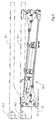
- the section of a sheet-fed rotary printing press illustrated in FIG. 1 comprises a delivery device 1 following a last processing station.
- a processing station may be a printing unit or a post-treatment unit, such as a coating unit.
- the last processing station is an offset printing unit 2 with a printing cylinder 2.1. This leads a respective sheet 3 in a direction indicated by the direction of arrow 5 processing direction through a pressure gap between the impression cylinder 2.1 and a cooperating blanket cylinder 2.2 and then passes it to a chain conveyor 4 under opening arranged on the impression cylinder 2.1, for detecting the sheet 3 at a Gripper edge provided on the leading end of the sheet grippers.
- the chain conveyor 4 comprises two conveyor chains 6, of which a respective one operatively rotates along a respective side wall of the chain jib 1.
- a respective conveyor chain 6 wraps around each one of two synchronously driven drive sprockets 7, whose axes of rotation are aligned with each other, and is guided in the present example via one Umlenkkettenrad 8 located downstream of the drive sprockets 7 downstream with respect to the processing direction.
- both conveyor chains 6 extend from these supported gripper systems 9 with grippers 9.1, which pass through gaps between the arranged on the printing cylinder 2.1 grippers and arranged a respective sheet 3 under detection of said gripper edge at the leading end of the sheet 3 immediately before the opening of the printing cylinder 2.1 Take over gripper, transport him across a sheet guiding device 10 to a sheet brake 11 and there open to the transfer of the sheet 3 to the sheet brake 11.
- the conveyor chains 6 are guided along their paths between the drive sprockets 7 on the one hand and the Umlenkketten impartn 8 on the other hand by means of chain guide rails, which thus determine the chain tracks of the chain.
- the sheets 3 are transported by the lower in Fig. 1 chain.
- the traversed by this section of the chain track follows a facing this, formed on the sheet guiding device 10 sheet guide surface 17.
- a supporting air cushion is formed between this and the respective over-carried sheet 3 preferably operationally.
- a dryer 19 and a dusting device 20 are provided on the way the sheet 3 of the drive sprockets 7 to the sheet brake 11.
- a coolant circuit is integrated into the sheet guiding device 10, which is indicated in Fig. 1 by a coolant trough 23.
- FIG. 2 shows a plan view of a supply station 24 adjacent to the stacking station 14, preferably here upstream of the stacking station 14 with respect to the processing direction, in the area of which, as can be seen in FIG. 1, in a side wall 1.1 of the jib 1, an insertion opening 25 Inserting a stack support 26 is provided in the delivery station 24.
- a lifting and lowering rectangular frame 27 extends beyond the stacking station 14 and the provisioning station 24 with lateral frame legs 27.1 and 27.2 arranged in the region of a respective one of the side walls 1.1 and 1.2, which are connected together at their respective ends by means of a traverse 27.3 and 27.4 are (see Fig. 5).
- the Frame legs 27.1 and 27.2 carry a along this between the staging station 24 and the stacking station 14 displaced, designed to receive a stack base 26 U-shaped carriage 28 with legs 28.1 and 28.2 and connecting them, visible in Fig. 3, the stacking station 14 facing away from the bridge 28.3.
- the frame legs 27.1 and 27.2 are formed as hollow profiles, in which linear actuators are housed.
- the legs 28.1 and 28.2 of the carriage 28 are connected via the frame legs 27.1 and 27.2 cross-driver with the linear drives and arranged in the immediate vicinity of the frame legs 27.1 and 27.2.
- the frame 27 with the linear drives and the carriages 28 integrated therein form a conveyor by means of which a respective stacking support 26 introduced into the provisioning station 24 and placed on the carriage 28 can be brought into the stacking station 14.
- the carriage 28 is designed to receive a respective stack support 26.
- the legs 28.1 and 28.2 of the carriage 28 are each provided with an L-shaped cross-section such that a respective L captures a respective lateral edge region of a stack support 26 and a stop for a respective lateral end side of the stack support 26, which is here in the form of a hurdle board.
- a stack base support 29 is arranged with a support 29.1 adjustable between a first level and a second level lower than this second level.
- the stack base support 29 is, as can be seen in particular in Fig. 3, inserted into a arranged on the underside of the frame 27 and carried by this tray 30 and attached to a tub bottom 30.1 of the tub 30 and he has the shape of a lifting table with a support 29.1 trained table surface 29.1 and a bearing 29.1 bearing, actuated by means of an actuating cylinder 29.2 hoist 29.3, here in the form of a linkage with a pivot lever assembly.
- Fig. 4 shows the lifting table in a detached from the boom 1 representation, the hoist 29.3 is shown in a position in which the support 29.1 is at its lower second level.
- the support 29.1 is shown both in its position on the second and in its position at the higher first level.
- a ramp 31 is arranged on the already mentioned insertion opening 25 having side wall 1.1 of the jib 1 in an advantageous embodiment. This supports the latter during an initial phase of manual loading of the staging station 24 with a stacking pad 26, thus providing further ease of introduction to the staging station 24.
- this first level is matched with the positions of the insertion opening 25 and the ramp 31 in such a way that unimpeded insertion of the stack support 26 into the delivery station 24 is possible.
- the support By means of a return stroke of the piston for positioning the stack support 26 on the support 29.1 extended piston rod of the actuating cylinder 29.2 29.1 the support is lowered from its first level to its lower second level.
- This second level is defined such that the stack support 26 previously deposited on the table surface 29.1 'is lifted off the table surface 29.1' during the lowering of the support 29.1 by the legs 28.1 and 28.2 of the carriage 28 and thus transferred to the conveyor comprising the carriage 28 ,
- a further facilitation is provided by a further conveyor 35 provided in a further embodiment, by means of which the stack support 26 can be fed to the stack support carrier 29.
- This further conveyor 35 preferably comprises a conveyor roller 35.2 connected to a drive 35.1, wherein the drive 35.1, as shown by the example according to FIG. 5, is advantageously arranged within the conveyor roller 35.2.
- the feed roller 35.2 is an outer ring of an electric motor designed as an outer ring rotor.
- the feed roller 35.2 is associated with the support 29.1 at its insertion opening 25 facing the end and slightly surmounted the 29.1 formed on the support table surface 29.1, the altitude of the feed roller 35.2 not on closer manner is adjustable within certain limits.
- stack support 26 of this conveyor 35 further preferably comprises a roller assembly 35.3, the axis parallel to the conveyor roller 35.2 arranged and biased towards them in the present embodiment by means of torsion springs 35.3 ' is.
- a stack support 26 which has been brought into the area of the conveying roller 35.2, is clamped between the conveying roller 35.2 and the roller arrangement 35.3 due to the aforementioned pretensioning of the latter.
- the stacking station 14 with stacking pads 26 further includes a stop 36 is provided, the maximum wall thickness of the Stacking tray carrier 29 feedable stacking pads 26 limited to a predetermined amount.
- the stop 36 is formed in the form of a recognizable in Fig. 3 in cross-section rod which extends transversely to the insertion direction of the stack support 26 along the insertion opening 25.
- a sensor 37 indicated in FIG. 3 is provided, which generates a signal after complete insertion of the stacking support 26 into the provisioning station 24, if one with respect to the insertion direction trailing end of the stack support 26 deviates from a predetermined position.
- the trailing end of a respective stack support 26 takes in its stop 34 for the leading edge in the insertion direction of the stack support 26 adjacent layer, that is, after complete insertion of the stack support 26 in the supply station 24 then a predetermined position, if it under lowering the support 29.1 is received in the L-shaped recess of the leg 28.1 of the carriage 28. Otherwise, the lateral extent of the stack support 26 is too large or too small.
- the said linear drives integrated in the frame 27 can then be blocked.
- these provisions preferably provide that a housing 38 surrounding the insertion opening 25 is arranged on the outside of the side wall 1.1 having the insertion opening 25, which ramp 31, one of the insertion opening 25 upstream opening 38.1 for pushing through the stack support 26 and a flap 38.2, which closes the opening 38.1 in a first position thereof, in a second position, the opening 38.1 for inserting the stack support 26 releases and can be locked in the first position.
- the housing 38 has a bottom in the form of the aforementioned ramp 31. This is about a horizontal axis 38.3 at one of the side wall 1.1 remote from the end of the housing 38 pivotally suspended from the latter and is supported with its side wall 1.1 facing the end of the frame 27 from.
- the ramp 31 thus adapts optionally to different altitudes of the raised and lowered frame 27 as mentioned.
- Fig. 3 the flap 38.2 is shown in its opening 38.1 occlusive first position.
- Fig. 6 shows the essential parts of an embodiment of a locking mechanism 39 for locking the flap 38.2 in the opening 38.1 occlusive first position.
- the Locking mechanism 39 a rectangular in cross-section, located in the region of a side wall 38.4 of the housing 38 located end piece of the flap 38.2 fixed and pivotally mounted on the housing 38 flap axis 39.1, and a pivotally mounted on the side wall 38.4 arranged latch 39.2 in the form of a two-armed lever a trained for positive engagement of the tail of the damper shaft 39.1 mouth at a first end of the lever and engaging the second end of the lever, articulated on the side wall 38.4, for example pneumatically actuable actuating cylinder 39.3, by means of which the mouth of the bolt 39.2 in or out of engagement with said end piece the flap axis 39.1 can be brought.
Landscapes
- Engineering & Computer Science (AREA)
- Mechanical Engineering (AREA)
- Pile Receivers (AREA)
- Forming Counted Batches (AREA)
- Supply, Installation And Extraction Of Printed Sheets Or Plates (AREA)
- Processing And Handling Of Plastics And Other Materials For Molding In General (AREA)
- Making Paper Articles (AREA)
- Perforating, Stamping-Out Or Severing By Means Other Than Cutting (AREA)
- Sheets, Magazines, And Separation Thereof (AREA)
- Discharge By Other Means (AREA)
Applications Claiming Priority (2)
| Application Number | Priority Date | Filing Date | Title |
|---|---|---|---|
| DE10045883A DE10045883A1 (de) | 2000-09-14 | 2000-09-14 | Ausleger für eine flechige Bedruckstoffe verarbeitende Maschine |
| DE10045883 | 2000-09-14 |
Publications (3)
| Publication Number | Publication Date |
|---|---|
| EP1188701A2 EP1188701A2 (de) | 2002-03-20 |
| EP1188701A3 EP1188701A3 (de) | 2004-03-17 |
| EP1188701B1 true EP1188701B1 (de) | 2006-01-18 |
Family
ID=7656472
Family Applications (1)
| Application Number | Title | Priority Date | Filing Date |
|---|---|---|---|
| EP01118896A Expired - Lifetime EP1188701B1 (de) | 2000-09-14 | 2001-08-17 | Ausleger für eine flächige Bedruckstoffe verarbeitende Maschine |
Country Status (8)
| Country | Link |
|---|---|
| US (1) | US6776411B2 (cs) |
| EP (1) | EP1188701B1 (cs) |
| JP (1) | JP4944320B2 (cs) |
| CN (1) | CN1224563C (cs) |
| AT (1) | ATE316057T1 (cs) |
| CZ (1) | CZ297110B6 (cs) |
| DE (2) | DE10045883A1 (cs) |
| HK (1) | HK1045831B (cs) |
Families Citing this family (6)
| Publication number | Priority date | Publication date | Assignee | Title |
|---|---|---|---|---|
| JP4227824B2 (ja) * | 2003-03-28 | 2009-02-18 | 三菱重工業株式会社 | 枚葉印刷機の排紙装置 |
| US8103344B2 (en) * | 2006-10-31 | 2012-01-24 | St. Jude Medical Ab | Method, device, implantable stimulator and dual chamber cardiac therapy system |
| CH699866A1 (de) * | 2008-11-04 | 2010-05-14 | Ferag Ag | Vorrichtung und verfahren zum zusammentragen von flachen gegenständen. |
| CN104249551B (zh) * | 2014-03-26 | 2016-08-24 | 天津长荣印刷设备股份有限公司 | 一种上平台的传动装置及其工作方法 |
| CN104773589A (zh) * | 2015-04-10 | 2015-07-15 | 霍山县雁江印务有限公司 | 一种印刷机防粘机构 |
| CN115158802B (zh) * | 2020-12-01 | 2024-05-07 | 广东东方精工科技股份有限公司 | 一种铲纸架的延后插入方法 |
Family Cites Families (36)
| Publication number | Priority date | Publication date | Assignee | Title |
|---|---|---|---|---|
| USRE23641E (en) * | 1953-04-14 | Sheetsxsheet i | ||
| DE476374C (de) * | 1927-08-05 | 1929-07-09 | Muller J C & Co | Vorrichtung zum Ablegen, Stapeln und Zaehlen von einer endlosen Bahn abgetrennter Zuschnitte |
| US2795420A (en) * | 1954-11-03 | 1957-06-11 | Jr George F Rooney | Sheet catching and stacking device for a printing press |
| US3233891A (en) * | 1963-01-17 | 1966-02-08 | Weyerhaeuser Co | Stacker |
| DE1230810B (de) * | 1964-11-21 | 1966-12-22 | Jagenberg Werke Ag | Verfahren und Vorrichtung zum Erleichtern des Einfuehrens von Hilfsstapeltischen beim Wechseln des Stapels an Querschneidemaschinen od. dgl. |
| US3410424A (en) * | 1967-02-27 | 1968-11-12 | George F. Rooney Jr. | Rack for holding a stack of printed sheets |
| DE2329767C3 (de) * | 1973-06-12 | 1975-12-04 | Roland Offsetmaschinenfabrik Faber & Schleicher Ag, 6050 Offenbach | Bogenausleger |
| DE2758291C3 (de) * | 1977-12-27 | 1980-07-10 | Jagenberg-Werke Ag, 4000 Duesseldorf | Stapelwechselvorrichtung |
| JPS6050713B2 (ja) * | 1979-03-07 | 1985-11-09 | 大日本印刷株式会社 | 枚葉印刷機の排紙装置 |
| DE2935710C2 (de) * | 1978-09-09 | 1981-12-03 | Dai Nippon Insatsu K.K., Tokyo | Vorrichtung zum Ablegen von Blättern zu einem Stapel |
| CA1194511A (en) * | 1981-04-24 | 1985-10-01 | Friedhelm Mundus | Apparatus for stacking flat articles |
| JPS6212570A (ja) * | 1985-07-10 | 1987-01-21 | Akiyama Insatsuki Seizo Kk | 枚葉印刷機の排紙装置におけるすのこ板操作機構 |
| JPH0757667B2 (ja) * | 1986-08-04 | 1995-06-21 | 株式会社小森コーポレーション | 枚葉印刷機の板取り板挿入装置 |
| JPS63295367A (ja) * | 1987-05-28 | 1988-12-01 | Toppan Printing Co Ltd | 枚葉印刷機排紙部の一時紙受装置 |
| JPH01197273A (ja) * | 1988-01-30 | 1989-08-08 | Dainippon Printing Co Ltd | 枚葉印刷機の排紙装置 |
| DD286559A5 (de) * | 1988-03-31 | 1991-01-31 | Veb Kombinat Polygraph "Werner Lamberz" Leipzig,De | Sicherheitseinrichtung in auslagen von druckmaschinen |
| JPH0252855A (ja) * | 1988-08-13 | 1990-02-22 | Dainippon Printing Co Ltd | 枚葉印刷機排紙部の板入れガイド装置 |
| DE3911969A1 (de) * | 1989-04-12 | 1990-10-18 | Jagenberg Ag | Vorrichtung zum riesweisen ablegen von boegen, insbesondere papierboegen, auf einen stapel |
| CH682995A5 (fr) * | 1990-04-26 | 1993-12-31 | Bobst Sa | Dispositif d'interception de feuilles déposées sur le haut d'une pile dans une machine de production d'emballages. |
| JP2788536B2 (ja) * | 1990-06-01 | 1998-08-20 | 株式会社小森コーポレーション | 板取り板挿入装置及び板取り板挿入方法 |
| US5240370A (en) * | 1990-06-01 | 1993-08-31 | Komori Corporation | Pile board inserting method and a pile board inserting machine for carrying out the same |
| DE4029919C1 (cs) * | 1990-09-21 | 1992-04-02 | Jagenberg Ag, 4000 Duesseldorf, De | |
| DE4131015C2 (de) * | 1991-09-18 | 1995-10-05 | Roland Man Druckmasch | Bogenausleger |
| DE4217816C2 (de) * | 1992-05-29 | 1995-01-26 | Heidelberger Druckmasch Ag | Einrichtung zur kontinuierlichen Auslage flächiger Druckprodukte |
| DE4221928B4 (de) * | 1992-07-03 | 2004-06-24 | Heidelberger Druckmaschinen Ag | Vorrichtung zum Non-Stop-Stapelwechsel im Ausleger einer Druckmaschine |
| JPH06239514A (ja) * | 1993-02-19 | 1994-08-30 | Mitsubishi Heavy Ind Ltd | 枚葉印刷機の自動板取り装置 |
| DE4344361C2 (de) * | 1993-02-27 | 1996-10-17 | Heidelberger Druckmasch Ag | Vorrichtung zur Bildung einzelner Bogenstapel |
| ATE151383T1 (de) | 1993-02-27 | 1997-04-15 | Heidelberger Druckmasch Ag | Einrichtung zur bildung einzelner bogenstapel |
| DE4317357C1 (de) * | 1993-05-25 | 1994-11-24 | Roland Man Druckmasch | Verfahren und Vorrichtung zur exakten Trennung eines Hilfsstapels von einem Hauptstapel bei Non-Stop-Auslegern von bogenverarbeitenden Druckmaschinen |
| DE19612294C2 (de) * | 1996-03-28 | 1998-01-29 | Heidelberger Druckmasch Ag | Auslagesystem für flächige Produkte |
| DE19649319C2 (de) * | 1996-11-28 | 1999-12-09 | Heidelberger Druckmasch Ag | Vorrichtung zur Handhabung von aus Bogen gebildeten Stapeln |
| CZ284297B6 (cs) * | 1997-05-19 | 1998-10-14 | Dobrušské Strojírny, A.S. | Zařízení pro zvedání stohu archů papíru k nakládací hlavě tiskařského stroje |
| DE19928252A1 (de) * | 1998-07-11 | 2000-01-13 | Heidelberger Druckmasch Ag | Vorrichtung und Verfahren zur Durchführung von Hürdenbetrieb im Ausleger einer Bogendruckmaschine |
| JP3357616B2 (ja) * | 1998-11-27 | 2002-12-16 | リョービ株式会社 | 枚葉印刷装置の板取り作業管理装置 |
| DE19928367A1 (de) * | 1999-06-21 | 2000-12-28 | Will E C H Gmbh & Co | Verfahren und Vorrichtung zum Wechseln von Paletten für Bogenstapel |
| US6497549B2 (en) * | 2000-12-27 | 2002-12-24 | J & L Development, Inc. | Counter-ejector |
-
2000
- 2000-09-14 DE DE10045883A patent/DE10045883A1/de not_active Withdrawn
-
2001
- 2001-08-03 CZ CZ20012827A patent/CZ297110B6/cs not_active IP Right Cessation
- 2001-08-17 AT AT01118896T patent/ATE316057T1/de not_active IP Right Cessation
- 2001-08-17 DE DE50108730T patent/DE50108730D1/de not_active Expired - Lifetime
- 2001-08-17 EP EP01118896A patent/EP1188701B1/de not_active Expired - Lifetime
- 2001-09-12 JP JP2001275919A patent/JP4944320B2/ja not_active Expired - Fee Related
- 2001-09-14 US US09/952,739 patent/US6776411B2/en not_active Expired - Fee Related
- 2001-09-14 CN CNB011421754A patent/CN1224563C/zh not_active Expired - Fee Related
-
2002
- 2002-10-03 HK HK02107273.1A patent/HK1045831B/zh not_active IP Right Cessation
Also Published As
| Publication number | Publication date |
|---|---|
| CN1224563C (zh) | 2005-10-26 |
| CN1343617A (zh) | 2002-04-10 |
| HK1045831B (zh) | 2006-07-07 |
| ATE316057T1 (de) | 2006-02-15 |
| CZ297110B6 (cs) | 2006-09-13 |
| HK1045831A1 (en) | 2002-12-13 |
| DE50108730D1 (de) | 2006-04-06 |
| EP1188701A3 (de) | 2004-03-17 |
| JP2002104715A (ja) | 2002-04-10 |
| US20020084577A1 (en) | 2002-07-04 |
| EP1188701A2 (de) | 2002-03-20 |
| JP4944320B2 (ja) | 2012-05-30 |
| US6776411B2 (en) | 2004-08-17 |
| CZ20012827A3 (cs) | 2002-08-14 |
| DE10045883A1 (de) | 2002-03-28 |
Similar Documents
| Publication | Publication Date | Title |
|---|---|---|
| EP0535360B1 (de) | Bogenausleger | |
| DE3153613C2 (cs) | ||
| EP0790206B1 (de) | Verfahren und Vorrichtung zum automatischen Stapelwechsel | |
| EP0470362B1 (de) | Bogen verarbeitende Maschine und damit zusammenarbeitende Transporteinrichtung für Bogenstapel | |
| EP2093176B1 (de) | Bogenbremseinrichtung | |
| DE3613462C2 (cs) | ||
| EP1188701B1 (de) | Ausleger für eine flächige Bedruckstoffe verarbeitende Maschine | |
| DE2058606A1 (de) | Verfahren und Vorrichtung zum seitlichen Ausrichten von Blaettern,insbesondere bei einer Druckpresse | |
| DE102020207420A1 (de) | Vorrichtung zur Druckplatten-Handhabung an einer Druckmaschine | |
| EP0389827A2 (de) | Bogenausleger an Rotationsdruckmaschinen | |
| DE10049181B4 (de) | Vorrichtung zum Ausschleusen von Probe-und Fehlerbogen aus einer Bogen verarbeitenden Maschine | |
| DE102008005797A1 (de) | Ausleger einer bogenverarbeitenden Maschine, insbesondere Bogendruckmaschine | |
| DE3320552C2 (de) | Bogentransporteinrichtung einer Bogen-Rotations-Offsetdruckmaschine | |
| EP0668230B1 (de) | Vorrichtung zur exakten Trennung von Haupt- und Hilfsstapel an der Bogenhinterkante bei Non-Stop-Anlegern | |
| EP1136409B1 (de) | Vorrichtung zum Abbremsen von Probe- und Fehlerbogen einer Bogen verarbeitenden Maschine | |
| EP0939701B1 (de) | Stapelhandling einer druckmaschine | |
| DE29619951U1 (de) | Vorrichtung zum automatischen Stapelwechsel | |
| DE3444849C2 (cs) | ||
| DE10211007A1 (de) | Vorrichtung zum Unterfangen von Bogen | |
| DE19911524C2 (de) | Vorrichtung zum Wechseln von Bogenstapeln in einem Ausleger einer Bogendruckmaschine | |
| DE3431611C2 (cs) | ||
| DE4139388C2 (de) | Anordnung zum kontinuierlichen Entsorgen einer Bogendruckmaschine | |
| DE102016109947A1 (de) | Auslegevorrichtung an einer Bogenrotationsdruckmaschine | |
| DE4013173C2 (de) | Verfahren und Vorrichtung zum automatischen Beschicken eines Bogenanlegers | |
| DE102004058375B4 (de) | Bogenanschlag in einem Bogenausleger |
Legal Events
| Date | Code | Title | Description |
|---|---|---|---|
| PUAI | Public reference made under article 153(3) epc to a published international application that has entered the european phase |
Free format text: ORIGINAL CODE: 0009012 |
|
| AK | Designated contracting states |
Kind code of ref document: A2 Designated state(s): AT BE CH CY DE DK ES FI FR GB GR IE IT LI LU MC NL PT SE TR |
|
| AX | Request for extension of the european patent |
Free format text: AL;LT;LV;MK;RO;SI |
|
| PUAL | Search report despatched |
Free format text: ORIGINAL CODE: 0009013 |
|
| AK | Designated contracting states |
Kind code of ref document: A3 Designated state(s): AT BE CH CY DE DK ES FI FR GB GR IE IT LI LU MC NL PT SE TR |
|
| AX | Request for extension of the european patent |
Extension state: AL LT LV MK RO SI |
|
| RIC1 | Information provided on ipc code assigned before grant |
Ipc: 7B 65H 29/04 B Ipc: 7B 65H 33/02 A |
|
| 17P | Request for examination filed |
Effective date: 20040211 |
|
| AKX | Designation fees paid |
Designated state(s): AT BE CH CY DE DK ES FI FR GB GR IE IT LI LU MC NL PT SE TR |
|
| GRAP | Despatch of communication of intention to grant a patent |
Free format text: ORIGINAL CODE: EPIDOSNIGR1 |
|
| GRAS | Grant fee paid |
Free format text: ORIGINAL CODE: EPIDOSNIGR3 |
|
| GRAA | (expected) grant |
Free format text: ORIGINAL CODE: 0009210 |
|
| AK | Designated contracting states |
Kind code of ref document: B1 Designated state(s): AT BE CH CY DE DK ES FI FR GB GR IE IT LI LU MC NL PT SE TR |
|
| PG25 | Lapsed in a contracting state [announced via postgrant information from national office to epo] |
Ref country code: IT Free format text: LAPSE BECAUSE OF FAILURE TO SUBMIT A TRANSLATION OF THE DESCRIPTION OR TO PAY THE FEE WITHIN THE PRESCRIBED TIME-LIMIT;WARNING: LAPSES OF ITALIAN PATENTS WITH EFFECTIVE DATE BEFORE 2007 MAY HAVE OCCURRED AT ANY TIME BEFORE 2007. THE CORRECT EFFECTIVE DATE MAY BE DIFFERENT FROM THE ONE RECORDED. Effective date: 20060118 Ref country code: IE Free format text: LAPSE BECAUSE OF FAILURE TO SUBMIT A TRANSLATION OF THE DESCRIPTION OR TO PAY THE FEE WITHIN THE PRESCRIBED TIME-LIMIT Effective date: 20060118 Ref country code: NL Free format text: LAPSE BECAUSE OF FAILURE TO SUBMIT A TRANSLATION OF THE DESCRIPTION OR TO PAY THE FEE WITHIN THE PRESCRIBED TIME-LIMIT Effective date: 20060118 Ref country code: FI Free format text: LAPSE BECAUSE OF FAILURE TO SUBMIT A TRANSLATION OF THE DESCRIPTION OR TO PAY THE FEE WITHIN THE PRESCRIBED TIME-LIMIT Effective date: 20060118 |
|
| REG | Reference to a national code |
Ref country code: GB Ref legal event code: FG4D Free format text: NOT ENGLISH |
|
| REG | Reference to a national code |
Ref country code: CH Ref legal event code: EP |
|
| REG | Reference to a national code |
Ref country code: IE Ref legal event code: FG4D Free format text: LANGUAGE OF EP DOCUMENT: GERMAN |
|
| REF | Corresponds to: |
Ref document number: 50108730 Country of ref document: DE Date of ref document: 20060406 Kind code of ref document: P |
|
| PG25 | Lapsed in a contracting state [announced via postgrant information from national office to epo] |
Ref country code: DK Free format text: LAPSE BECAUSE OF FAILURE TO SUBMIT A TRANSLATION OF THE DESCRIPTION OR TO PAY THE FEE WITHIN THE PRESCRIBED TIME-LIMIT Effective date: 20060418 Ref country code: SE Free format text: LAPSE BECAUSE OF FAILURE TO SUBMIT A TRANSLATION OF THE DESCRIPTION OR TO PAY THE FEE WITHIN THE PRESCRIBED TIME-LIMIT Effective date: 20060418 |
|
| PG25 | Lapsed in a contracting state [announced via postgrant information from national office to epo] |
Ref country code: ES Free format text: LAPSE BECAUSE OF FAILURE TO SUBMIT A TRANSLATION OF THE DESCRIPTION OR TO PAY THE FEE WITHIN THE PRESCRIBED TIME-LIMIT Effective date: 20060429 |
|
| GBT | Gb: translation of ep patent filed (gb section 77(6)(a)/1977) |
Effective date: 20060420 |
|
| PG25 | Lapsed in a contracting state [announced via postgrant information from national office to epo] |
Ref country code: PT Free format text: LAPSE BECAUSE OF FAILURE TO SUBMIT A TRANSLATION OF THE DESCRIPTION OR TO PAY THE FEE WITHIN THE PRESCRIBED TIME-LIMIT Effective date: 20060619 |
|
| NLV1 | Nl: lapsed or annulled due to failure to fulfill the requirements of art. 29p and 29m of the patents act | ||
| REG | Reference to a national code |
Ref country code: IE Ref legal event code: FD4D |
|
| PG25 | Lapsed in a contracting state [announced via postgrant information from national office to epo] |
Ref country code: MC Free format text: LAPSE BECAUSE OF NON-PAYMENT OF DUE FEES Effective date: 20060831 Ref country code: BE Free format text: LAPSE BECAUSE OF NON-PAYMENT OF DUE FEES Effective date: 20060831 |
|
| ET | Fr: translation filed | ||
| PLBE | No opposition filed within time limit |
Free format text: ORIGINAL CODE: 0009261 |
|
| STAA | Information on the status of an ep patent application or granted ep patent |
Free format text: STATUS: NO OPPOSITION FILED WITHIN TIME LIMIT |
|
| 26N | No opposition filed |
Effective date: 20061019 |
|
| PG25 | Lapsed in a contracting state [announced via postgrant information from national office to epo] |
Ref country code: AT Free format text: LAPSE BECAUSE OF NON-PAYMENT OF DUE FEES Effective date: 20060817 |
|
| BERE | Be: lapsed |
Owner name: HEIDELBERGER DRUCKMASCHINEN A.G. Effective date: 20060831 |
|
| PG25 | Lapsed in a contracting state [announced via postgrant information from national office to epo] |
Ref country code: GR Free format text: LAPSE BECAUSE OF FAILURE TO SUBMIT A TRANSLATION OF THE DESCRIPTION OR TO PAY THE FEE WITHIN THE PRESCRIBED TIME-LIMIT Effective date: 20060419 |
|
| PG25 | Lapsed in a contracting state [announced via postgrant information from national office to epo] |
Ref country code: LU Free format text: LAPSE BECAUSE OF NON-PAYMENT OF DUE FEES Effective date: 20060817 Ref country code: TR Free format text: LAPSE BECAUSE OF FAILURE TO SUBMIT A TRANSLATION OF THE DESCRIPTION OR TO PAY THE FEE WITHIN THE PRESCRIBED TIME-LIMIT Effective date: 20060118 |
|
| PGFP | Annual fee paid to national office [announced via postgrant information from national office to epo] |
Ref country code: CH Payment date: 20080825 Year of fee payment: 8 |
|
| PG25 | Lapsed in a contracting state [announced via postgrant information from national office to epo] |
Ref country code: CY Free format text: LAPSE BECAUSE OF FAILURE TO SUBMIT A TRANSLATION OF THE DESCRIPTION OR TO PAY THE FEE WITHIN THE PRESCRIBED TIME-LIMIT Effective date: 20060118 |
|
| PGFP | Annual fee paid to national office [announced via postgrant information from national office to epo] |
Ref country code: FR Payment date: 20080822 Year of fee payment: 8 |
|
| PGFP | Annual fee paid to national office [announced via postgrant information from national office to epo] |
Ref country code: GB Payment date: 20080826 Year of fee payment: 8 |
|
| REG | Reference to a national code |
Ref country code: CH Ref legal event code: PL |
|
| GBPC | Gb: european patent ceased through non-payment of renewal fee |
Effective date: 20090817 |
|
| PG25 | Lapsed in a contracting state [announced via postgrant information from national office to epo] |
Ref country code: CH Free format text: LAPSE BECAUSE OF NON-PAYMENT OF DUE FEES Effective date: 20090831 Ref country code: LI Free format text: LAPSE BECAUSE OF NON-PAYMENT OF DUE FEES Effective date: 20090831 |
|
| REG | Reference to a national code |
Ref country code: FR Ref legal event code: ST Effective date: 20100430 |
|
| PG25 | Lapsed in a contracting state [announced via postgrant information from national office to epo] |
Ref country code: FR Free format text: LAPSE BECAUSE OF NON-PAYMENT OF DUE FEES Effective date: 20090831 |
|
| PG25 | Lapsed in a contracting state [announced via postgrant information from national office to epo] |
Ref country code: GB Free format text: LAPSE BECAUSE OF NON-PAYMENT OF DUE FEES Effective date: 20090817 |
|
| PGFP | Annual fee paid to national office [announced via postgrant information from national office to epo] |
Ref country code: DE Payment date: 20150831 Year of fee payment: 15 |
|
| REG | Reference to a national code |
Ref country code: DE Ref legal event code: R119 Ref document number: 50108730 Country of ref document: DE |
|
| PG25 | Lapsed in a contracting state [announced via postgrant information from national office to epo] |
Ref country code: DE Free format text: LAPSE BECAUSE OF NON-PAYMENT OF DUE FEES Effective date: 20170301 |