EP1188701B1 - Delivery apparatus for a machine processing flat printed materials - Google Patents
Delivery apparatus for a machine processing flat printed materials Download PDFInfo
- Publication number
- EP1188701B1 EP1188701B1 EP01118896A EP01118896A EP1188701B1 EP 1188701 B1 EP1188701 B1 EP 1188701B1 EP 01118896 A EP01118896 A EP 01118896A EP 01118896 A EP01118896 A EP 01118896A EP 1188701 B1 EP1188701 B1 EP 1188701B1
- Authority
- EP
- European Patent Office
- Prior art keywords
- pile
- station
- underlay
- delivery according
- conveyor
- Prior art date
- Legal status (The legal status is an assumption and is not a legal conclusion. Google has not performed a legal analysis and makes no representation as to the accuracy of the status listed.)
- Expired - Lifetime
Links
Images


Classifications
-
- B—PERFORMING OPERATIONS; TRANSPORTING
- B65—CONVEYING; PACKING; STORING; HANDLING THIN OR FILAMENTARY MATERIAL
- B65H—HANDLING THIN OR FILAMENTARY MATERIAL, e.g. SHEETS, WEBS, CABLES
- B65H33/00—Forming counted batches in delivery pile or stream of articles
- B65H33/02—Forming counted batches in delivery pile or stream of articles by moving a blade or like member into the pile
-
- B—PERFORMING OPERATIONS; TRANSPORTING
- B65—CONVEYING; PACKING; STORING; HANDLING THIN OR FILAMENTARY MATERIAL
- B65H—HANDLING THIN OR FILAMENTARY MATERIAL, e.g. SHEETS, WEBS, CABLES
- B65H29/00—Delivering or advancing articles from machines; Advancing articles to or into piles
- B65H29/02—Delivering or advancing articles from machines; Advancing articles to or into piles by mechanical grippers engaging the leading edge only of the articles
- B65H29/04—Delivering or advancing articles from machines; Advancing articles to or into piles by mechanical grippers engaging the leading edge only of the articles the grippers being carried by endless chains or bands
- B65H29/041—Delivering or advancing articles from machines; Advancing articles to or into piles by mechanical grippers engaging the leading edge only of the articles the grippers being carried by endless chains or bands and introducing into a pile
-
- B—PERFORMING OPERATIONS; TRANSPORTING
- B65—CONVEYING; PACKING; STORING; HANDLING THIN OR FILAMENTARY MATERIAL
- B65H—HANDLING THIN OR FILAMENTARY MATERIAL, e.g. SHEETS, WEBS, CABLES
- B65H2801/00—Application field
- B65H2801/03—Image reproduction devices
- B65H2801/21—Industrial-size printers, e.g. rotary printing press
Definitions
- the invention relates to a boom for a sheet-fed printing machine, in particular a sheet-fed printing press, with a stacking station, in which are stacked to this in a processing direction conveyed sheet, a processing direction upstream of the stacking station located with a provision provided in a side wall Insertion opening for introducing a stack underlay into the supply station and a conveyor, by means of which the stack support introduced into the supply station can be brought into the stacking station and a machine equipped with the delivery area, in particular a printing press.
- a boom of the type mentioned is known from the document DE 196 12 294 C2.
- stacking documents are those in the form of a rake or a levitation table, one and the same stacker is, if appropriate, repeatedly moved back and forth between the provisioning station and the stacking station, at least for one and the same order to be processed by the machine.
- a necessary conversion of the boom to another stack underlay is at most necessary for a job change, and only if, for example, in the case of a stack provided in the form of a rake this is unsuitable for the case of stacking on non-grooved pallets to a Stack change during the Performing printing so that the boom must be converted to a stack underlay in the form of said floating table.
- a mounted stack support in the form of the rake or the levitation table thus remains in use for a relatively long period of time, as in the stack change using a rake or a levitation table as an auxiliary stack carrier forming stack support depending on the type of pallet used, the auxiliary stack carrier by case Case is always one and the same.
- a device for mechanized, emanating from a staging station loading a stacking station with lost stacking documents, in particular with hurdles is known from the document DE 43 44 361 C2.
- the staging station disclosed therein a plurality of stacked stacking pads are stored in a magazine from which each of the lowermost by means of a between the staging station and the stacking station reciprocally movable and equipped with carriers rake in the stacking station is transportable. Information about a filling of the magazine can not be found in the cited document. However, it is conceivable that the magazine is filled by manually inserting the stack documents before the start of a print job.
- the known device is therefore quite advantageous for hurdles deployable as long as a print job does not exceed a certain amount of circulation and thus a certain number of required hurdles.
- the disclosed in the aforementioned document DE 196 12 294 C2 boom is in principle suitable for the case of exceeding a certain amount of circulation.
- the boom disclosed in the last-mentioned publication offers only a slot-shaped lateral opening of a side wall of the jib, through which a stacking support in the form of a hurdle board is to be transferred to the delivery station and transferred to the conveyor, which has only frame legs for receiving the stack support. which are arranged in the vicinity of a respective side wall.
- the introduction of a stack underlay through said insertion opening thus proves to be extremely difficult.
- the invention has for its object to form the aforementioned boom so that the introduction of stacking pads is facilitated in the staging and can be carried out in a very short time.
- a stack underlay carrier is arranged in the staging station with a support adjustable between a first level and a lower second level, which receives at its first level the stack underlay introduced into the staging station and under adjustment towards the second level Sponsor hands over.
- each inserted through the insertion opening in the staging station stacking support is pushed onto the stack support base, which then aligns the stack support in the required manner so that after the successful insertion of the Stacking pad this is transferred to the conveyor under lowering of the stack base support, after the stack support has been spent by the said alignment in a horizontal position.
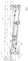
- the section of a sheet-fed rotary printing press illustrated in FIG. 1 comprises a delivery device 1 following a last processing station.
- a processing station may be a printing unit or a post-treatment unit, such as a coating unit.
- the last processing station is an offset printing unit 2 with a printing cylinder 2.1. This leads a respective sheet 3 in a direction indicated by the direction of arrow 5 processing direction through a pressure gap between the impression cylinder 2.1 and a cooperating blanket cylinder 2.2 and then passes it to a chain conveyor 4 under opening arranged on the impression cylinder 2.1, for detecting the sheet 3 at a Gripper edge provided on the leading end of the sheet grippers.
- the chain conveyor 4 comprises two conveyor chains 6, of which a respective one operatively rotates along a respective side wall of the chain jib 1.
- a respective conveyor chain 6 wraps around each one of two synchronously driven drive sprockets 7, whose axes of rotation are aligned with each other, and is guided in the present example via one Umlenkkettenrad 8 located downstream of the drive sprockets 7 downstream with respect to the processing direction.
- both conveyor chains 6 extend from these supported gripper systems 9 with grippers 9.1, which pass through gaps between the arranged on the printing cylinder 2.1 grippers and arranged a respective sheet 3 under detection of said gripper edge at the leading end of the sheet 3 immediately before the opening of the printing cylinder 2.1 Take over gripper, transport him across a sheet guiding device 10 to a sheet brake 11 and there open to the transfer of the sheet 3 to the sheet brake 11.
- the conveyor chains 6 are guided along their paths between the drive sprockets 7 on the one hand and the Umlenkketten impartn 8 on the other hand by means of chain guide rails, which thus determine the chain tracks of the chain.
- the sheets 3 are transported by the lower in Fig. 1 chain.
- the traversed by this section of the chain track follows a facing this, formed on the sheet guiding device 10 sheet guide surface 17.
- a supporting air cushion is formed between this and the respective over-carried sheet 3 preferably operationally.
- a dryer 19 and a dusting device 20 are provided on the way the sheet 3 of the drive sprockets 7 to the sheet brake 11.
- a coolant circuit is integrated into the sheet guiding device 10, which is indicated in Fig. 1 by a coolant trough 23.
- FIG. 2 shows a plan view of a supply station 24 adjacent to the stacking station 14, preferably here upstream of the stacking station 14 with respect to the processing direction, in the area of which, as can be seen in FIG. 1, in a side wall 1.1 of the jib 1, an insertion opening 25 Inserting a stack support 26 is provided in the delivery station 24.
- a lifting and lowering rectangular frame 27 extends beyond the stacking station 14 and the provisioning station 24 with lateral frame legs 27.1 and 27.2 arranged in the region of a respective one of the side walls 1.1 and 1.2, which are connected together at their respective ends by means of a traverse 27.3 and 27.4 are (see Fig. 5).
- the Frame legs 27.1 and 27.2 carry a along this between the staging station 24 and the stacking station 14 displaced, designed to receive a stack base 26 U-shaped carriage 28 with legs 28.1 and 28.2 and connecting them, visible in Fig. 3, the stacking station 14 facing away from the bridge 28.3.
- the frame legs 27.1 and 27.2 are formed as hollow profiles, in which linear actuators are housed.
- the legs 28.1 and 28.2 of the carriage 28 are connected via the frame legs 27.1 and 27.2 cross-driver with the linear drives and arranged in the immediate vicinity of the frame legs 27.1 and 27.2.
- the frame 27 with the linear drives and the carriages 28 integrated therein form a conveyor by means of which a respective stacking support 26 introduced into the provisioning station 24 and placed on the carriage 28 can be brought into the stacking station 14.
- the carriage 28 is designed to receive a respective stack support 26.
- the legs 28.1 and 28.2 of the carriage 28 are each provided with an L-shaped cross-section such that a respective L captures a respective lateral edge region of a stack support 26 and a stop for a respective lateral end side of the stack support 26, which is here in the form of a hurdle board.
- a stack base support 29 is arranged with a support 29.1 adjustable between a first level and a second level lower than this second level.
- the stack base support 29 is, as can be seen in particular in Fig. 3, inserted into a arranged on the underside of the frame 27 and carried by this tray 30 and attached to a tub bottom 30.1 of the tub 30 and he has the shape of a lifting table with a support 29.1 trained table surface 29.1 and a bearing 29.1 bearing, actuated by means of an actuating cylinder 29.2 hoist 29.3, here in the form of a linkage with a pivot lever assembly.
- Fig. 4 shows the lifting table in a detached from the boom 1 representation, the hoist 29.3 is shown in a position in which the support 29.1 is at its lower second level.
- the support 29.1 is shown both in its position on the second and in its position at the higher first level.
- a ramp 31 is arranged on the already mentioned insertion opening 25 having side wall 1.1 of the jib 1 in an advantageous embodiment. This supports the latter during an initial phase of manual loading of the staging station 24 with a stacking pad 26, thus providing further ease of introduction to the staging station 24.
- this first level is matched with the positions of the insertion opening 25 and the ramp 31 in such a way that unimpeded insertion of the stack support 26 into the delivery station 24 is possible.
- the support By means of a return stroke of the piston for positioning the stack support 26 on the support 29.1 extended piston rod of the actuating cylinder 29.2 29.1 the support is lowered from its first level to its lower second level.
- This second level is defined such that the stack support 26 previously deposited on the table surface 29.1 'is lifted off the table surface 29.1' during the lowering of the support 29.1 by the legs 28.1 and 28.2 of the carriage 28 and thus transferred to the conveyor comprising the carriage 28 ,
- a further facilitation is provided by a further conveyor 35 provided in a further embodiment, by means of which the stack support 26 can be fed to the stack support carrier 29.
- This further conveyor 35 preferably comprises a conveyor roller 35.2 connected to a drive 35.1, wherein the drive 35.1, as shown by the example according to FIG. 5, is advantageously arranged within the conveyor roller 35.2.
- the feed roller 35.2 is an outer ring of an electric motor designed as an outer ring rotor.
- the feed roller 35.2 is associated with the support 29.1 at its insertion opening 25 facing the end and slightly surmounted the 29.1 formed on the support table surface 29.1, the altitude of the feed roller 35.2 not on closer manner is adjustable within certain limits.
- stack support 26 of this conveyor 35 further preferably comprises a roller assembly 35.3, the axis parallel to the conveyor roller 35.2 arranged and biased towards them in the present embodiment by means of torsion springs 35.3 ' is.
- a stack support 26 which has been brought into the area of the conveying roller 35.2, is clamped between the conveying roller 35.2 and the roller arrangement 35.3 due to the aforementioned pretensioning of the latter.
- the stacking station 14 with stacking pads 26 further includes a stop 36 is provided, the maximum wall thickness of the Stacking tray carrier 29 feedable stacking pads 26 limited to a predetermined amount.
- the stop 36 is formed in the form of a recognizable in Fig. 3 in cross-section rod which extends transversely to the insertion direction of the stack support 26 along the insertion opening 25.
- a sensor 37 indicated in FIG. 3 is provided, which generates a signal after complete insertion of the stacking support 26 into the provisioning station 24, if one with respect to the insertion direction trailing end of the stack support 26 deviates from a predetermined position.
- the trailing end of a respective stack support 26 takes in its stop 34 for the leading edge in the insertion direction of the stack support 26 adjacent layer, that is, after complete insertion of the stack support 26 in the supply station 24 then a predetermined position, if it under lowering the support 29.1 is received in the L-shaped recess of the leg 28.1 of the carriage 28. Otherwise, the lateral extent of the stack support 26 is too large or too small.
- the said linear drives integrated in the frame 27 can then be blocked.
- these provisions preferably provide that a housing 38 surrounding the insertion opening 25 is arranged on the outside of the side wall 1.1 having the insertion opening 25, which ramp 31, one of the insertion opening 25 upstream opening 38.1 for pushing through the stack support 26 and a flap 38.2, which closes the opening 38.1 in a first position thereof, in a second position, the opening 38.1 for inserting the stack support 26 releases and can be locked in the first position.
- the housing 38 has a bottom in the form of the aforementioned ramp 31. This is about a horizontal axis 38.3 at one of the side wall 1.1 remote from the end of the housing 38 pivotally suspended from the latter and is supported with its side wall 1.1 facing the end of the frame 27 from.
- the ramp 31 thus adapts optionally to different altitudes of the raised and lowered frame 27 as mentioned.
- Fig. 3 the flap 38.2 is shown in its opening 38.1 occlusive first position.
- Fig. 6 shows the essential parts of an embodiment of a locking mechanism 39 for locking the flap 38.2 in the opening 38.1 occlusive first position.
- the Locking mechanism 39 a rectangular in cross-section, located in the region of a side wall 38.4 of the housing 38 located end piece of the flap 38.2 fixed and pivotally mounted on the housing 38 flap axis 39.1, and a pivotally mounted on the side wall 38.4 arranged latch 39.2 in the form of a two-armed lever a trained for positive engagement of the tail of the damper shaft 39.1 mouth at a first end of the lever and engaging the second end of the lever, articulated on the side wall 38.4, for example pneumatically actuable actuating cylinder 39.3, by means of which the mouth of the bolt 39.2 in or out of engagement with said end piece the flap axis 39.1 can be brought.
Abstract
Description
Die Erfindung betrifft einen Ausleger für eine flächige Bedruckstoffe verarbeitende Maschine, insbesondere eine Bogen verarbeitende Druckmaschine, mit einer Stapelstation, in welcher zu dieser in einer Verarbeitungsrichtung beförderte Bogen gestapelt werden, einer bezüglich der Verarbeitungsrichtung stromaufwärts gegenüber der Stapelstation gelegenen Bereitstellungsstation mit einer in einer Seitenwand vorgesehenen Einschuböffnung zum Einführen einer Stapelunterlage in die Bereitstellungsstation und einem Förderer, mittels welchem die in die Bereitstellungsstation eingeführte Stapelunterlage in die Stapelstation verbringbar ist sowie eine mit dem Ausleger ausgestattete flächige Bedruckstoffe verarbeitende Maschine, insbesondere eine Druckmaschine.The invention relates to a boom for a sheet-fed printing machine, in particular a sheet-fed printing press, with a stacking station, in which are stacked to this in a processing direction conveyed sheet, a processing direction upstream of the stacking station located with a provision provided in a side wall Insertion opening for introducing a stack underlay into the supply station and a conveyor, by means of which the stack support introduced into the supply station can be brought into the stacking station and a machine equipped with the delivery area, in particular a printing press.
Ein Ausleger der genannten Art ist aus der Druckschrift DE 196 12 294 C2 bekannt. Diese offenbart einen Förderer, mittels welchem Stapelunterlagen unterschiedlicher Art von der genannten Bereitstellungsstation in die genannte Stapelstation transportierbar sind. Insoweit es sich bei diesen Stapelunterlagen um solche in Form eines Rechens oder eines Schwebetisches handelt, wird zumindest bei ein und demselben von der Maschine abzuarbeitenden Auftrag ein und dieselbe Stapelunterlage gegebenenfalls mehrfach zwischen der Bereitstellungsstation und der Stapelstation hin und her verfahren. Eine notwendige Umrüstung des Auslegers auf eine andere Stapelunterlage ist dabei allenfalls bei einem Auftragswechsel erforderlich, und auch nur dann, wenn beispielsweise im Falle einer in Form eines Rechens vorgesehenen Stapelunterlage diese für den Fall der Stapelbildung auf nicht mit Nuten versehenen Paletten ungeeignet ist, um einen Stapelwechsel während des Fortdruckes durchzuführen, so dass der Ausleger auf eine Stapelunterlage in Form des genannten Schwebetisches umgerüstet werden muss. Eine montierte Stapelunterlage in Form des Rechens oder des Schwebetisches verbleibt also in der Regel über einen relativ großen Zeitraum im Einsatz, da beim Stapelwechsel unter Verwendung eines Rechens oder eines Schwebetisches als eine einen Hilfsstapelträger bildende Stapelunterlage je nach Art der verwendeten Palette der Hilfsstapelträger von Fall zu Fall immer ein und derselbe ist.A boom of the type mentioned is known from the document DE 196 12 294 C2. This discloses a conveyor, by means of which stacking documents of different types of the said delivery station in said stacking station are transportable. Insofar as these stacking documents are those in the form of a rake or a levitation table, one and the same stacker is, if appropriate, repeatedly moved back and forth between the provisioning station and the stacking station, at least for one and the same order to be processed by the machine. A necessary conversion of the boom to another stack underlay is at most necessary for a job change, and only if, for example, in the case of a stack provided in the form of a rake this is unsuitable for the case of stacking on non-grooved pallets to a Stack change during the Performing printing so that the boom must be converted to a stack underlay in the form of said floating table. A mounted stack support in the form of the rake or the levitation table thus remains in use for a relatively long period of time, as in the stack change using a rake or a levitation table as an auxiliary stack carrier forming stack support depending on the type of pallet used, the auxiliary stack carrier by case Case is always one and the same.
Im Falle einer Hürdenbildung ist jedoch für jeden zu bildenden Teilstapel eine weitere Stapelunterlage in Form eines Hürdenbrettes erforderlich.In the case of a hurdle formation, however, a further stack underlay in the form of a hurdle board is required for each partial stack to be formed.
Eine Vorrichtung zur mechanisierten, von einer Bereitstellungsstation ausgehenden Beschickung einer Stapelstation mit verlorenen Stapelunterlagen, wie insbesondere mit Hürdenbrettern, ist aus der Druckschrift DE 43 44 361 C2 bekannt. In der darin offenbarten Bereitstellungsstation ist eine Mehrzahl von aufeinandergeschichteten Stapelunterlagen in einem Magazin bevorratet, aus welchem die jeweils unterste mittels eines zwischen der Bereitstellungsstation und der Stapelstation hin und her verfahrbaren und mit Mitnehmern ausgestatteten Rechens in die Stapelstation transportierbar ist. Angaben über eine Befüllung des Magazins sind der genannten Druckschrift nicht entnehmbar. Es ist jedoch vorstellbar, dass das Magazin vor Beginn eines Druckauftrags durch manuelles Einlegen der Stapelunterlagen aufgefüllt wird. Die bekannte Vorrichtung ist damit durchaus vorteilhaft zur Hürdenauslage einsetzbar solange ein Druckauftrag eine gewisse Auflagenhöhe und damit eine gewisse Anzahl von erforderlichen Hürdenbrettern nicht überschreitet.A device for mechanized, emanating from a staging station loading a stacking station with lost stacking documents, in particular with hurdles, is known from the document DE 43 44 361 C2. In the staging station disclosed therein, a plurality of stacked stacking pads are stored in a magazine from which each of the lowermost by means of a between the staging station and the stacking station reciprocally movable and equipped with carriers rake in the stacking station is transportable. Information about a filling of the magazine can not be found in the cited document. However, it is conceivable that the magazine is filled by manually inserting the stack documents before the start of a print job. The known device is therefore quite advantageous for hurdles deployable as long as a print job does not exceed a certain amount of circulation and thus a certain number of required hurdles.
Der in der eingangs genannten Druckschrift DE 196 12 294 C2 offenbarte Ausleger ist für den Fall einer Überschreitung einer gewissen Auflagenhöhe zwar grundsätzlich geeignet. Es verbleibt hierbei jedoch die Schwierigkeit des Einbringens entsprechender Stapelunterlagen in die Bereitstellungsstation. Der in der letztgenannten Druckschrift offenbarte Ausleger bietet hierzu lediglich eine schlitzförmige seitliche Öffnung einer Seitenwand des Auslegers an, durch welche jeweils eine Stapelunterlage in Form eines Hürdenbrettes in die Bereitstellungsstation verbracht und an der Förderer übergeben werden soll, der zur Aufnahme der Stapelunterlage lediglich Rahmenschenkel aufweist, die in der Nachbarschaft einer jeweiligen Seitenwand angeordnet sind. Das Einbringen einer Stapelunterlage durch die besagte Einschuböffnung erweist sich damit als äußerst schwierig.The disclosed in the aforementioned document DE 196 12 294 C2 boom is in principle suitable for the case of exceeding a certain amount of circulation. However, this leaves the difficulty of introducing appropriate stacking pads into the staging station. For this purpose, the boom disclosed in the last-mentioned publication offers only a slot-shaped lateral opening of a side wall of the jib, through which a stacking support in the form of a hurdle board is to be transferred to the delivery station and transferred to the conveyor, which has only frame legs for receiving the stack support. which are arranged in the vicinity of a respective side wall. The introduction of a stack underlay through said insertion opening thus proves to be extremely difficult.
Der Erfindung liegt die Aufgabe zugrunde, den eingangs genannten Ausleger so auszubilden, dass das Einbringen von Stapelunterlagen in die Bereitstellungsstation erleichtert wird und in kürzester Zeit durchführbar ist.The invention has for its object to form the aforementioned boom so that the introduction of stacking pads is facilitated in the staging and can be carried out in a very short time.
Zur Lösung dieser Aufgabe ist in der Bereitstellungsstation ein Stapelunterlagenträger mit einem zwischen einem ersten Niveau und einem gegenüber diesem tieferen zweiten Niveau verstellbaren Auflager angeordnet, welches auf seinem ersten Niveau die in die Bereitstellungsstation eingeführte Stapelunterlage aufnimmt und unter Verstellung in Richtung auf das zweite Niveau an den Förderer übergibt.To solve this problem, a stack underlay carrier is arranged in the staging station with a support adjustable between a first level and a lower second level, which receives at its first level the stack underlay introduced into the staging station and under adjustment towards the second level Sponsor hands over.
Bei dieser Ausgestaltung ist eine jeweils durch die Einschuböffnung in die Bereitstellungsstation eingeführte Stapelunterlage auf den Stapelunterlagenträger aufschiebbar, welcher die Stapelunterlage sodann in erforderlicher Weise derart ausrichtet, dass nach erfolgtem Einschieben der Stapelunterlage diese unter Absenkung des Stapelunterlagenträgers an den Förderer übergeben wird, nachdem die Stapelunterlage durch die besagte Ausrichtung in eine waagerechte Lage verbracht wurde.In this embodiment, each inserted through the insertion opening in the staging station stacking support is pushed onto the stack support base, which then aligns the stack support in the required manner so that after the successful insertion of the Stacking pad this is transferred to the conveyor under lowering of the stack base support, after the stack support has been spent by the said alignment in a horizontal position.
Bevorzugte Ausgestaltungen und Weiterbildungen des Erfindungsgegenstandes sind den beigefügten Zeichnungen und der darauf Bezug nehmenden nachfolgenden näheren Erläuterung entnehmbar.Preferred embodiments and further developments of the subject invention are the appended drawings and the subsequent reference to further detailed explanation.
In den Zeichnungen zeigt:
- Fig. 1
- eine schematische Darstellung eines Endabschnittes einer Bogen verarbeitenden Druckmaschine, wobei der Endabschnitt den eingangs genannten Ausleger mit einer Stapelstation und einer Bereitstellungsstation umfasst, und wobei die erfindungsgemäße Ausbildung hier lediglich grob angedeutet ist,
- Fig. 2
- eine Draufsicht auf die Stapelstation und die Bereitstellungsstation, wobei auf eine vollständige Darstellung aller Komponenten verzichtet ist,
- Fig. 3
- einen quer zur Verarbeitungsrichtung geführten Schnitt durch die Bereitstellungsstation,
- Fig. 4
- ein Detail aus Fig. 3 in Form eines dort erkennbaren Hubmechanismusses, mittels welchem ein Auflager zur Aufnahme einer Stapelunterlage zwischen einem ersten Niveau und einem tieferen zweiten Niveau verstellbar ist, in einer dem zweiten Niveau entsprechenden Stellung des Hubmechanismusses und in Form eines von diesem getragenen Auflagers in dem ersten und dem zweiten Niveau entsprechenden Höhenlagen,
- Fig. 5
- ein Ausführungsbeispiel einer Förderwalze mit einem innerhalb dieser angeordneten Antrieb für dieselbe,
- Fig. 6
- Details einer Ansicht in Richtung des Pfeils VI in Fig. 2.
- Fig. 1
- 2 a schematic representation of an end section of a sheet-processing printing press, wherein the end section comprises the aforementioned arm with a stacking station and a staging station, and wherein the embodiment according to the invention is only roughly indicated here,
- Fig. 2
- a top view of the stacking station and the staging station, with a complete representation of all components is omitted,
- Fig. 3
- a cross-machine direction cut by the staging station;
- Fig. 4
- a detail of Fig. 3 in the form of a recognizable there Hubmechanismusses, by means of which a support for receiving a stack support between a first level and a lower second level is adjustable, in a second Level corresponding position of the Hubmechanismusses and in the form of a supported by this support in the first and the second level corresponding altitude,
- Fig. 5
- An embodiment of a conveyor roller with a arranged within this drive for the same,
- Fig. 6
- Details of a view in the direction of the arrow VI in Fig. 2.
Der in Fig. 1 dargestellte Abschnitt einer Bogen verarbeitenden Rotationsdruckmaschine umfasst einen auf eine letzte Verarbeitungsstation folgenden Ausleger 1. Eine solche Verarbeitungsstation kann ein Druckwerk oder ein Nachbehandlungswerk sein, wie beispielsweise ein Lackwerk. Im vorliegenden Beispiel handelt es sich bei der letzten Verarbeitungsstation um ein im Offsetverfahren arbeitendes Druckwerk 2 mit einem Druckzylinder 2.1. Dieser führt einen jeweiligen Bogen 3 in einer mittels des Richtungspfeils 5 angedeuteten Verarbeitungsrichtung durch einen Druckspalt zwischen dem Druckzylinder 2.1 und einem damit zusammenarbeitenden Gummituchzylinder 2.2 und übergibt ihn anschließend an einen Kettenförderer 4 unter Öffnen von am Druckzylinder 2.1 angeordneten, zum Erfassen des Bogens 3 an einem Greiferrand am vorauseilenden Ende des Bogens vorgesehenen Greifern. Der Kettenförderer 4 umfasst zwei Förderketten 6, von welchen eine jeweilige entlang einer jeweiligen Seitenwand des Kettenauslegers 1 betriebsmäßig umläuft. Eine jeweilige Förderkette 6 umschlingt je eines von zwei synchron angetriebenen Antriebskettenrädern 7, deren Drehachsen miteinander fluchten, und ist im vorliegenden Beispiel über je ein gegenüber den Antriebskettenrädern 7 stromabwärts bezüglich der Verarbeitungsrichtung befindliches Umlenkkettenrad 8 geführt. Zwischen den beiden Förderketten 6 erstrecken sich von diesen getragene Greifersysteme 9 mit Greifern 9.1, welche Lücken zwischen den am Druckzylinder 2.1 angeordneten Greifern durchfahren und dabei einen jeweiligen Bogen 3 unter Erfassen des genannten Greiferrandes am vorauseilenden Ende des Bogens 3 unmittelbar vor dem Öffnen der am Druckzylinder 2.1 angeordneten Greifer übernehmen, ihn über eine Bogenleitvorrichtung 10 hinweg zu einer Bogenbremse 11 transportieren und sich dort zur Übergabe des Bogens 3 an die Bogenbremse 11 öffnen. Diese vermittelt den Bogen eine gegenüber der Verarbeitungsgeschwindigkeit verringerte Ablagegeschwindigkeit und gibt sie nach Erreichen derselben ihrerseits frei, so dass ein jeweiliger nunmehr verlangsamter Bogen 3 in einer Stapelstation 14 schließlich auf Vorderkantenanschläge 12 auftrifft und unter Ausrichtung an diesen und an diesen gegenüberliegenden, quer zur Verarbeitungsrichtung schwenkbaren Hinterkantenanschlägen 13 gemeinsam mit vorausgegangenen und/oder nachfolgenden Bogen 3 einen Stapel 14.1 bildet, der mittels eines Hubwerkes in dem Maße absenkbar ist, wie der Stapel 14.1 anwächst. Von dem Hubwerk sind in Fig. 1 lediglich eine den Stapel 14.1 tragende Plattform 15 und diese tragende, strichpunktiert angedeutete Hubketten 16 wiedergegeben.The section of a sheet-fed rotary printing press illustrated in FIG. 1 comprises a delivery device 1 following a last processing station. Such a processing station may be a printing unit or a post-treatment unit, such as a coating unit. In the present example, the last processing station is an
Die Förderketten 6 sind entlang ihrer Wege zwischen den Antriebskettenrädern 7 einerseits und den Umlenkkettenrädern 8 andererseits mittels Kettenführungsschienen geführt, welche somit die Kettenbahnen der Kettentrume bestimmen. Im vorliegenden Beispiel werden die Bogen 3 von dem in Fig. 1 unteren Kettentrum transportiert. Dem von diesem durchlaufenen Abschnitt der Kettenbahn folgt eine diesem zugewandte, an der Bogenleitvorrichtung 10 ausgebildete Bogenleitfläche 17. Zwischen dieser und dem jeweils darüber hinweggeführten Bogen 3 ist bevorzugt betriebsmäßig ein Tragluftpolster ausgebildet. Hierzu ist die Bogenleitvorrichtung 10 mit in die Bogenleitfläche 17 mündenden hier nicht dargestellten Blasluftdüsen ausgestattet.The
Um ein gegenseitiges Verkleben der bedruckten Bogen 3 im Stapel 14.1 zu verhindern, sind auf dem Weg der Bogen 3 von den Antriebskettenrädern 7 zur Bogenbremse 11 ein Trockner 19 und eine Bestäubungsvorrichtung 20 vorgesehen.In order to prevent mutual sticking of the printed
Zur Vermeidung einer übermäßigen Erwärmung der Bogenleitfläche 17 durch den Trockner 19 ist in die Bogenleitvorrichtung 10 ein Kühlmittelkreislauf integriert, der in Fig. 1 durch eine Kühlmittelwanne 23 angedeutet ist.To avoid excessive heating of the
Die Fig. 2 zeigt in einer Draufsicht eine benachbart zur Stapelstation 14, hier bevorzugt bezüglich der Verarbeitungsrichtung stromaufwärts gegenüber der Stapelstation 14 vorgesehene Bereitstellungsstation 24, in deren Bereich, wie in Fig. 1 erkennbar, in einer Seitenwand 1.1 des Auslegers 1 eine Einschuböffnung 25 zum Einführen einer Stapelunterlage 26 in die Bereitstellungsstation 24 vorgesehen ist. Zwischen der Stapelstation 14 und der Bereitstellungsstation 24 besteht eine funktionelle Anbindung über einen im weiteren Verlauf erläuterten Förderer, mittels welchem die in die Bereitstellungsstation 24 eingeführte Stapelunterlage 26 in die Stapelstation 14 verbringbar ist.FIG. 2 shows a plan view of a
Über die Stapelstation 14 und die Bereitstellungsstation 24 hinweg erstreckt sich ein heb- und senkbarer rechteckiger Rahmen 27 mit seitlichen, im Bereich einer jeweiligen der Seitenwände 1.1 und 1.2 angeordneten Rahmenschenkeln 27.1 und 27.2, die an deren jeweiligen Enden mittels einer Traverse 27.3 und 27.4 miteinander verbunden sind (siehe Fig. 5). Die Rahmenschenkel 27.1 und 27.2 tragen einen entlang dieser zwischen der Bereitstellungsstation 24 und der Stapelstation 14 hin und her verschiebbaren, zur Aufnahme einer Stapelunterlage 26 ausgebildeten U-förmigen Schlitten 28 mit Schenkeln 28.1 und 28.2 und einem diese verbindenden, in Fig. 3 erkennbaren, der Stapelstation 14 abgewandten Steg 28.3. Die Rahmenschenkel 27.1 und 27.2 sind als Hohlprofile ausgebildet, in welchen Linearantriebe untergebracht sind. Die Schenkel 28.1 und 28.2 des Schlittens 28 sind über die Rahmenschenkel 27.1 und 27.2 durchgreifende Mitnehmer mit den Linearantrieben verbunden und in unmittelbarer Nachbarschaft zu den Rahmenschenkeln 27.1 und 27.2 angeordnet.A lifting and lowering
Der Rahmen 27 mit den darin integrierten Linearantrieben und der Schlitten 28 bilden einen Förderer, mittels welchem eine jeweilige in die Bereitstellungsstation 24 eingeführte, auf dem Schlitten 28 abgelegte Stapelunterlage 26 in die Stapelstation 14 verbringbar ist.The
Zur Realisierung des genannten Förderers im Einzelnen wird bevorzugt auf die in DE 196 12 294 C2 in Bezug auf das dortige Hilfsstapelaufnahmeelement und den dortigen Hilfsstapelrahmen dargelegte Ausgestaltung zurückgegriffen.For the realization of said conveyor in detail, reference is preferably made to the embodiment set forth in DE 196 12 294 C2 with respect to the local auxiliary pile receiving element and the auxiliary pile stack there.
Der Schlitten 28 ist zur Aufnahme einer jeweiligen Stapelunterlage 26 ausgebildet. Hierzu sind, wie in Fig. 3 erkennbar, die Schenkel 28.1 und 28.2 des Schlittens 28 jeweils derartig mit einem L-förmigen Querschnitt versehen, dass ein jeweiliges L einen jeweiligen seitlichen Randbereich einer Stapelunterlage 26 unterfängt und einen Anschlag für eine jeweilige seitliche Stirnseite der Stapelunterlage 26 ausbildet, die hier in Form eines Hürdenbrettes vorliegt.The
In der Bereitstellungsstation 24 ist ein Stapelunterlagenträger 29 mit einem zwischen einem ersten Niveau und einem gegenüber diesem tieferen zweiten Niveau verstellbaren Auflager 29.1 angeordnet. Der Stapelunterlagenträger 29 ist, wie insbesondere in Fig. 3 erkennbar, in eine an der Unterseite des Rahmens 27 angeordnete und von diesem getragene Wanne 30 eingesetzt und an einem Wannenboden 30.1 der Wanne 30 befestigt und er besitzt die Form eines Hubtisches mit einer am Auflager 29.1 ausgebildeten Tischfläche 29.1 und eines das Auflager 29.1 tragenden, mittels eines Stellzylinders 29.2 betätigbaren Hubwerkes 29.3, hier in Form eines Gelenkgetriebes mit einer Schwenkhebelanordnung.In the staging
Die Fig. 4 zeigt den Hubtisch in einer aus dem Ausleger 1 herausgelösten Darstellung, wobei das Hubwerk 29.3 in einer Stellung wiedergegeben ist, in welcher sich das Auflager 29.1 auf dessen tieferen zweiten Niveau befindet. Das Auflager 29.1 ist sowohl in dessen Lage auf dem zweiten als auch in dessen Lage auf dem höheren ersten Niveau dargestellt.Fig. 4 shows the lifting table in a detached from the boom 1 representation, the hoist 29.3 is shown in a position in which the support 29.1 is at its lower second level. The support 29.1 is shown both in its position on the second and in its position at the higher first level.
Wie der Fig. 3 weiterhin entnehmbar, ist an der die bereits erwähnte Einschuböffnung 25 aufweisenden Seitenwand 1.1 des Auslegers 1 in vorteilhafter Ausgestaltung eine Rampe 31 angeordnet. Diese stützt während einer Anfangsphase der hier manuellen Beschickung der Bereitstellungsstation 24 mit einer Stapelunterlage 26 die letztere ab und erbringt somit eine weitere Erleichterung beim Einbringen derselben in die Bereitstellungsstation 24.As shown in FIG. 3 further removed, a
Der die Wanne 30 und somit den Stapelunterlagenträger 29 tragende und, wie bereits erwähnt, heb- und senkbare Rahmen 27 nimmt wenigstens während des Einschiebens der Stapelunterlage 26 durch die Einschuböffnung 25 in die Bereitstellungsstation 24 eine derartige Höhenlage ein, dass die Stapelunterlage 26 unter Einschieben in die Bereitstellungsstation 24 an die Tischfläche 29.1' des mittels des Hubwerkes 29 auf dem ersten Niveau gehaltenen Auflagers 29.1 übergebbar ist. Das von dem Auflager 29.1, genauer von dessen Tischfläche 29.1 ' eingenommene erste Niveau liegt hierbei oberhalb der Schenkel 28.1 und 28.2 des Schlittens 28, zumindest jedoch oberhalb derjenigen durch den L-förmigen Querschnitt von dessen Schenkeln 28.1 und 28.2 gebildeten Stützflächen, welche zum Unterfangen der seitlichen Randbereiche der Stapelunterlage 26 vorgesehen sind. Im übrigen ist dieses erste Niveau derart mit den Lagen der Einschuböffnung 25 und der Rampe 31 abgestimmt, dass ein ungehindertes Einführen der Stapelunterlage 26 in die Bereitstellungsstation 24 möglich ist.The
Zum lagegerechten Positionieren der Stapelunterlage 26 auf dem Auflager 29.1 des Stapelunterlagenträgers 29 während der Übergabe der Stapelunterlage 26 an die Tischfläche 29.1' des Auflagers 29.1 sind an dem Rahmen 27 die in Einschubrichtung seitlichen Stirnflächen der Stapelunterlage 26 führende Führungsschienen 32 und 33 und eine Anschlagschiene 34 angeordnet.For positionally correct positioning of the
Mittels eines Rückhubes der zum Positionieren der Stapelunterlage 26 auf dem Auflager 29.1 ausgefahrenen Kolbenstange des Stellzylinder 29.2 wird das Auflager 29.1 von seinem ersten Niveau auf sein tiefer gelegenes zweites Niveau abgesenkt. Dieses zweite Niveau ist derart definiert, dass die zuvor auf der Tischfläche 29.1' abgelegte Stapelunterlage 26 während des Absenkens des Auflagers 29.1 seitens der Schenkel 28.1 und 28.2 des Schlittens 28 von der Tischfläche 29.1' abgehoben und damit an den den Schlitten 28 umfassenden Förderer übergeben wird.By means of a return stroke of the piston for positioning the
Eine weitere Erleichterung ergibt sich mit einem in weiterer Ausgestaltung vorgesehenen weiteren Förderer 35, mittels welchem die Stapelunterlage 26 dem Stapelunterlagenträger 29 zuführbar ist. Dieser weitere Förderer 35 umfasst bevorzugt eine mit einem Antrieb 35.1 verbundene Förderwalze 35.2, wobei der Antrieb 35.1, wie am Beispiel gemäß Fig. 5 gezeigt, vorteilhafterweise innerhalb der Förderwalze 35.2 angeordnet ist. Bei diesem Beispiel stellt die Förderwalze 35.2 einen Außenring eines als Außenringläufer ausgebildeten Elektromotors dar. Die Förderwalze 35.2 ist dem Auflager 29.1 an dessen der Einschuböffnung 25 zugewandten Ende zugeordnet und überragt geringfügig die am Auflager 29.1 ausgebildete Tischfläche 29.1, wobei die Höhenlage der Förderwalze 35.2 auf nicht näher dargestellte Weise in gewissen Grenzen einstellbar ist.A further facilitation is provided by a
Zur Gewährleistung eines sicheren Transportes der durch Hindurchschieben durch die Einschuböffnung 25 an den weiteren Förderer 35 übergebenen Stapelunterlage 26 umfasst dieser Förderer 35 des weiteren bevorzugt eine Rollenanordnung 35.3, die achsparallel zur Förderwalze 35.2 angeordnet und in Richtung auf diese im vorliegenden Ausführungsbeispiel mittels Schenkelfedern 35.3' vorgespannt ist. In der Position des Auflagers 29.1 auf seinem ersten Niveau ist eine in den Bereich der Förderwalze 35.2 verbrachte Stapelunterlage 26 zwischen der Förderwalze 35.2 und der Rollenanordnung 35.3 aufgrund der genannten Vorspannung der letzteren eingespannt.To ensure safe transport of the transferred by pushing through the
Zur Absicherung einer im Hinblick auf die Dimensionierung der Stapelunterlagen 26 korrekten Beschickung der Bereitstellungsstation 24 und damit der Stapelstation 14 mit Stapelunterlagen 26 ist des Weiteren ein Anschlag 36 vorgesehen, der die maximale Wandstärke der dem Stapelunterlagenträger 29 zuführbaren Stapelunterlagen 26 auf ein vorbestimmtes Maß beschränkt.To ensure a correct with regard to the dimensioning of the stacking
Im vorliegenden Beispiel ist der Anschlag 36 in Form einer in Fig. 3 im Querschnitt erkennbaren Stange ausgebildet, die sich quer zur Einschubrichtung der Stapelunterlage 26 entlang der Einschuböffnung 25 erstreckt.In the present example, the
Gemäß einer ebenfalls im Hinblick auf eine Beschickung der Bereitstellungsstation 24 mit korrekt dimensionierten Stapelunterlagen 26 getroffenen Vorkehrung ist ein in Fig. 3 angedeuteter Sensor 37 vorgesehen, der nach erfolgtem vollständigen Einschieben der Stapelunterlage 26 in die Bereitstellungsstation 24 ein Signal erzeugt, wenn ein bezüglich der Einschubrichtung nachlaufendes Ende der Stapelunterlage 26 von einer vorbestimmten Position abweicht.According to a provision also made with regard to a loading of the
Das nachlaufende Ende einer jeweiligen Stapelunterlage 26 nimmt in deren am Anschlag 34 für die in Einschubrichtung vorauseilende Stirnseite der Stapelunterlage 26 anliegenden Lage, das heißt nach erfolgtem vollständigen Einschieben der Stapelunterlage 26 in die Bereitstellungsstation 24 dann eine vorbestimmte Position ein, wenn es unter Absenken des Auflagers 29.1 in der L-förmigen Ausnehmung des Schenkels 28.1 des Schlittens 28 aufgenommen wird. Andernfalls ist die seitliche Erstreckung der Stapelunterlage 26 zu groß oder zu klein. Mittels des in diesen Fällen vom Sensor 37 erzeugten Signals sind sodann die genannten, im Rahmen 27 integrierten Linearantriebe blockierbar.The trailing end of a
Unter Berücksichtigung des Umstandes, dass die Bereitstellungsstation 24 von den umlaufenden Greifersystemen 9 durchfahren wird, sind in weiterer Ausgestaltung Sicherheitsvorkehrungen getroffen, die einen manuellen Eingriff in die Einschuböffnung 25 verhindern.Taking into account the fact that the
Wie in Fig. 3 erkennbar, sehen diese Vorkehrungen bevorzugt vor, dass an der Außenseite der der Einschuböffnung 25 aufweisenden Seitenwand 1.1 ein die Einschuböffnung 25 umgebendes Gehäuse 38 angeordnet ist, welches die Rampe 31, eine der Einschuböffnung 25 vorgeordnete Öffnung 38.1 zum Durchschieben der Stapelunterlage 26 und eine Klappe 38.2 umfasst, welche in einer ersten Stellung derselben die Öffnung 38.1 verschließt, in einer zweiten Stellung die Öffnung 38.1 zum Einschieben der Stapelunterlage 26 freigibt und in der ersten Stellung verriegelbar ist.As can be seen in FIG. 3, these provisions preferably provide that a
Das Gehäuse 38 weist einen Boden in Form der bereits genannten Rampe 31 auf. Diese ist um eine horizontale Achse 38.3 an einem der Seitenwand 1.1 abgewandten Ende des Gehäuses 38 schwenkbar an letzterem aufgehängt und stützt sich mit ihrem der Seitenwand 1.1 zugewandten Ende auf dem Rahmen 27 ab. Die Rampe 31 passt sich somit gegebenenfalls unterschiedlichen Höhenlagen des wie erwähnt heb- und senkbaren Rahmens 27 an.The
In Fig. 3 ist die Klappe 38.2 in ihrer die Öffnung 38.1 verschließenden ersten Stellung dargestellt.In Fig. 3, the flap 38.2 is shown in its opening 38.1 occlusive first position.
Die Fig. 6 zeigt die wesentlichen Teile eines Ausführungsbeispieles eines Verriegelungsmechanismusses 39 zur Verriegelung der Klappe 38.2 in deren die Öffnung 38.1 verschließender ersten Stellung. Hiernach umfasst der Verriegelungsmechanismus 39 ein im Querschnitt rechteckig ausgebildetes, im Bereich einer Seitenwand 38.4 des Gehäuses 38 gelegenes Endstück einer mit der Klappe 38.2 fest verbundenen und schwenkbar am Gehäuse 38 angeordneten Klappenachse 39.1, sowie einen schwenkbar an der Seitenwand 38.4 angeordneten Riegel 39.2 in Form eines zweiarmigen Hebels mit einem zum formschlüssigen Umgreifen des Endstückes der Klappenachse 39.1 ausgebildeten Maul an einem ersten Hebelende und einem am zweiten Hebelende angreifenden, an der Seitenwand 38.4 angelenkten, beispielsweise pneumatisch beaufschlagbaren Stellzylinder 39.3, mittels welchem das Maul des Riegels 39.2 in bzw. außer Eingriff mit dem genannten Endstück der Klappenachse 39.1 bringbar ist. Im Eingriff ist eine Schwenkbewegung der Klappe 38.2 aufgrund der Geometrie des Endstückes der Klappenachse 39.1 und des Maules des Riegels 39.2 blockiert. Dieser Fall liegt bevorzugt bei einem unbeaufschlagten Zustand des vorzugsweise einfachwirkend ausgebildeten Stellzylinders 39.3 vor.Fig. 6 shows the essential parts of an embodiment of a locking mechanism 39 for locking the flap 38.2 in the opening 38.1 occlusive first position. After that includes the Locking mechanism 39 a rectangular in cross-section, located in the region of a side wall 38.4 of the
- 11
- Auslegerboom
- 1.1, 1.21.1, 1.2
- Seitenwand des AuslegersSidewall of the boom
- 22
- Druckwerkprinting unit
- 2.12.1
- Druckzylinderpressure cylinder
- 2.22.2
- GummituchzylinderBlanket cylinder
- 33
- Bogenbow
- 44
- Kettenfördererchain conveyors
- 55
- Richtungspfeilarrow
- 66
- Förderketteconveyor chain
- 77
- Antriebskettenraddrive sprocket
- 88th
- Umlenkkettenradnose wheel
- 99
- Greifersystemgripper system
- 9.19.1
- Greifergrab
- 1010
- Bogenleitvorrichtungsheet guide
- 1111
- Bogenbremsesheet brake
- 1212
- VorderkantenanschlagLeading-edge stop
- 1313
- HinterkantenanschlagRear edge stop
- 1414
- Stapelstationstacking station
- 14.114.1
- Stapelstack
- 1515
- Plattformplatform
- 1616
- Hubkettelifting chain
- 1717
- Bogenleitflächesheet guide surface
- 1919
- Trocknerdryer
- 2020
- Bestäubungsvorrichtungpollination device
- 2323
- KühlmittelwanneCoolant tray
- 2424
- BereitstellungsstationReady station
- 2525
- Einschuböffnunginsertion opening
- 2626
- StapelunterlageStack base
- 2727
- Rahmenframe
- 27.1, 27.227.1, 27.2
- Rahmenschenkelframe legs
- 27.3, 27.427.3, 27.4
- Traversetraverse
- 2828
- Schlittencarriage
- 28.1, 28.228.1, 28.2
-
Schenkel des Schlittens 28Legs of the
carriage 28 - 28.328.3
-
Steg des Schlittens 28Bridge of the
carriage 28 - 2929
- StapelunterlagenträgerPile underlay carrier
- 29.129.1
-
Auflager des Stapelunterlagenträgers 29Support of the
stack base support 29 - 29.1'29.1 '
- Tischfläche des Auflagers 29.1Table surface of the support 29.1
- 29.229.2
- Stellzylinderactuating cylinder
- 29.329.3
- Hubwerkhoist
- 3030
- Wannetub
- 30.130.1
- WannenbodenWannenboden
- 3131
- Ramperamp
- 3232
- Führungsschieneguide rail
- 3333
- Führungsschieneguide rail
- 3434
- Anschlagschienestop rail
- 3535
- Fördererpromoter
- 35.135.1
- Antriebdrive
- 35.235.2
- Förderwalzeconveyor roller
- 35.335.3
- Rollenanordnungroller assembly
- 35.3'35.3 '
- SchenkelfederLeg spring
- 3636
- Anschlagattack
- 3737
- Sensorsensor
- 3838
- Gehäusecasing
- 38.138.1
- Öffnungopening
- 38.238.2
- Klappeflap
- 38.338.3
- Achseaxis
- 38.438.4
-
Seitenwand des Gehäuses 38Side wall of the
housing 38 - 3939
- Verriegelungsmechanismuslocking mechanism
- 39.139.1
- Klappenachsedamper shaft
- 39.239.2
- Riegelbars
- 39.339.3
- Stellzylinderactuating cylinder
Claims (12)
- Delivery (1) for a machine processing flat printing materials, in particular a printing press processing sheets, including a pile-forming station (14) wherein a pile is formed of sheets transported to the pile-fonning station (14) in a processing direction (5), a make-ready station (24) located upstream of the pile-forming station (14) with regard to the processing direction (5) and having an insertion opening (25) for inserting a pile underlay (26) into the make-ready station (24), and a conveyor (27, 28) for moving the pile underlay (26) inserted into the make-ready station (24) into the pile-forming station (14),
characterized in
that in the make-ready station (24), a pile underlay carrier (29) is provided that has a support (29.1),which is adjustable between a first level and a second level that is lower than the first level, and which, on the first level thereof, receives the pile underlay (26) inserted into the make-ready station (24) and transfers the pile underlay (26) to the conveyor (27, 28) while being adjusted in the direction of the second level. - Delivery according to claim 1,
characterized in
that the support (29.1) has a table surface (29.1') onto which the pile underlay is slidable. - Delivery according to claim 1,
characterized in
that a ramp (31) is provided, which supports the pile underlay (26) during an initial phase prior to the feeding of the pile underlay (26) to the pile underlay carrier (29). - Delivery according to claim 1,
characterized by
another conveyor (35) for feeding the pile underlay (26) to the pile underlay carner (29). - Delivery according to claim 4,
characterized in
that the further conveyor (35) comprises a conveyor roller (35.2) connected to a drive (35.1). - Delivery according to claim 5,
characterized in
that the drive (35.1) is arranged inside the conveying roller (35.2). - Delivery according to claim 5,
characterized by
a roller arrangement (35.3) arranged to be axially parallel with the conveying roller (35.2) and biased towards the latter. - Delivery according to claim 1,
characterized by
a stop (36) that restricts the maximum wall thickness of the pile underlays (26) feedable to the pile underlay carrier (29) to a predetermined value. - Delivery according to claim 1,
characterized by
a sensor (37) that generates a signal after a complete insertion of the pile underlay (26) into the make-ready station (24) if a trailing end of the pile underlay (26) as viewed in the insertion direction deviates from a predetermined position. - Delivery according to claim 3,
characterized in
that a housing (38) is provided, which surrounds the insertion opening (25) is provided and comprises the ramp (31), an opening that is located in front of the insertion opening (25) and through which the pile underlay (26) can be pushed, and a flap (38.2) which, in a first position, closes off the opening (38.1), in a second position clears the opening (38.1), in a second position and is lockable in the first position. - Delivery according to claim 3,
characterized in
that the conveyor (27, 28) comprises a carnage (28), that a frame (27) is provided carrying the pile underlay carrier (29) and accepting the carriage (28) so that the latter is reciprocatingly movable between the make-ready station (24) and the pile-forming station (14), and that the ramp (31) is suspended so as to be supportable on the frame and pivotable. - Machine processing flat printing materials, in particular a printing press processing sheets,
characterized by
a delivery according to at least one of claims 1 to 11.
Applications Claiming Priority (2)
| Application Number | Priority Date | Filing Date | Title |
|---|---|---|---|
| DE10045883A DE10045883A1 (en) | 2000-09-14 | 2000-09-14 | Boom for a machine that processes braided substrates |
| DE10045883 | 2000-09-14 |
Publications (3)
| Publication Number | Publication Date |
|---|---|
| EP1188701A2 EP1188701A2 (en) | 2002-03-20 |
| EP1188701A3 EP1188701A3 (en) | 2004-03-17 |
| EP1188701B1 true EP1188701B1 (en) | 2006-01-18 |
Family
ID=7656472
Family Applications (1)
| Application Number | Title | Priority Date | Filing Date |
|---|---|---|---|
| EP01118896A Expired - Lifetime EP1188701B1 (en) | 2000-09-14 | 2001-08-17 | Delivery apparatus for a machine processing flat printed materials |
Country Status (8)
| Country | Link |
|---|---|
| US (1) | US6776411B2 (en) |
| EP (1) | EP1188701B1 (en) |
| JP (1) | JP4944320B2 (en) |
| CN (1) | CN1224563C (en) |
| AT (1) | ATE316057T1 (en) |
| CZ (1) | CZ297110B6 (en) |
| DE (2) | DE10045883A1 (en) |
| HK (1) | HK1045831B (en) |
Families Citing this family (6)
| Publication number | Priority date | Publication date | Assignee | Title |
|---|---|---|---|---|
| JP4227824B2 (en) * | 2003-03-28 | 2009-02-18 | 三菱重工業株式会社 | Sheet-fed printing machine paper discharge device |
| WO2008054261A1 (en) * | 2006-10-31 | 2008-05-08 | St. Jude Medical Ab | Method, device, implantable stimulator and dual chamber cardiac therapy system |
| CH699866A1 (en) * | 2008-11-04 | 2010-05-14 | Ferag Ag | Device and method for collating flat objects. |
| CN104249551B (en) * | 2014-03-26 | 2016-08-24 | 天津长荣印刷设备股份有限公司 | The actuating device of a kind of upper mounting plate and method of work thereof |
| CN104773589A (en) * | 2015-04-10 | 2015-07-15 | 霍山县雁江印务有限公司 | Printing machine anti-sticking mechanism |
| CN115158802B (en) * | 2020-12-01 | 2024-05-07 | 广东东方精工科技股份有限公司 | Delayed insertion method of paper shoveling frame |
Family Cites Families (36)
| Publication number | Priority date | Publication date | Assignee | Title |
|---|---|---|---|---|
| USRE23641E (en) * | 1953-04-14 | Sheetsxsheet i | ||
| DE476374C (en) * | 1927-08-05 | 1929-07-09 | Muller J C & Co | Device for depositing, stacking and counting blanks cut from an endless web |
| US2795420A (en) * | 1954-11-03 | 1957-06-11 | Jr George F Rooney | Sheet catching and stacking device for a printing press |
| US3233891A (en) * | 1963-01-17 | 1966-02-08 | Weyerhaeuser Co | Stacker |
| DE1230810B (en) * | 1964-11-21 | 1966-12-22 | Jagenberg Werke Ag | Method and device to facilitate the introduction of auxiliary stacking tables when changing the stack on cross-cutting machines or the like. |
| US3410424A (en) * | 1967-02-27 | 1968-11-12 | George F. Rooney Jr. | Rack for holding a stack of printed sheets |
| DE2329767C3 (en) * | 1973-06-12 | 1975-12-04 | Roland Offsetmaschinenfabrik Faber & Schleicher Ag, 6050 Offenbach | Bow boom |
| DE2758291C3 (en) * | 1977-12-27 | 1980-07-10 | Jagenberg-Werke Ag, 4000 Duesseldorf | Stack changing device |
| DE2935710C2 (en) * | 1978-09-09 | 1981-12-03 | Dai Nippon Insatsu K.K., Tokyo | Device for depositing sheets in a stack |
| JPS6050713B2 (en) * | 1979-03-07 | 1985-11-09 | 大日本印刷株式会社 | Sheet-fed printing press discharge device |
| CA1194511A (en) * | 1981-04-24 | 1985-10-01 | Friedhelm Mundus | Apparatus for stacking flat articles |
| JPS6212570A (en) * | 1985-07-10 | 1987-01-21 | Akiyama Insatsuki Seizo Kk | Mechanism for operating drainboard in paper discharging device for paper printer |
| JPH0757667B2 (en) * | 1986-08-04 | 1995-06-21 | 株式会社小森コーポレーション | Sheet cutting plate insertion device for sheet-fed printing press |
| JPS63295367A (en) * | 1987-05-28 | 1988-12-01 | Toppan Printing Co Ltd | Paper temporarily receiving device in sheet printer discharge section |
| JPH01197273A (en) * | 1988-01-30 | 1989-08-08 | Dainippon Printing Co Ltd | Paper discharge device for paper sheet printer |
| DD286559A5 (en) * | 1988-03-31 | 1991-01-31 | Veb Kombinat Polygraph "Werner Lamberz" Leipzig,De | SAFETY DEVICE IN EXPRESSION OF PRESSURE MACHINES |
| JPH0252855A (en) * | 1988-08-13 | 1990-02-22 | Dainippon Printing Co Ltd | Plate insertion guide device of paper ejecting part for sheet printer |
| DE3911969A1 (en) * | 1989-04-12 | 1990-10-18 | Jagenberg Ag | DEVICE FOR GIANTLY PUTTING SHEETS, IN PARTICULAR PAPER SHEETS, ONTO A PACK |
| CH682995A5 (en) * | 1990-04-26 | 1993-12-31 | Bobst Sa | Device intercepting sheets deposited on top of a stack in a machine for producing packaging. |
| JP2788536B2 (en) * | 1990-06-01 | 1998-08-20 | 株式会社小森コーポレーション | Boarding board insertion device and boarding board insertion method |
| US5240370A (en) * | 1990-06-01 | 1993-08-31 | Komori Corporation | Pile board inserting method and a pile board inserting machine for carrying out the same |
| DE4029919C1 (en) * | 1990-09-21 | 1992-04-02 | Jagenberg Ag, 4000 Duesseldorf, De | |
| DE4131015C2 (en) * | 1991-09-18 | 1995-10-05 | Roland Man Druckmasch | Sheet boom |
| DE4217816C2 (en) * | 1992-05-29 | 1995-01-26 | Heidelberger Druckmasch Ag | Device for the continuous delivery of flat printed products |
| DE4221928B4 (en) | 1992-07-03 | 2004-06-24 | Heidelberger Druckmaschinen Ag | Device for non-stop stack change in the delivery of a printing press |
| JPH06239514A (en) * | 1993-02-19 | 1994-08-30 | Mitsubishi Heavy Ind Ltd | Automatic blanking device of paper sheet printing machine |
| DE4344361C2 (en) * | 1993-02-27 | 1996-10-17 | Heidelberger Druckmasch Ag | Device for forming individual stacks of sheets |
| CN1043874C (en) | 1993-02-27 | 1999-06-30 | 海德堡印刷机械股份公司 | Device for producing individual stacks of sheets |
| DE4317357C1 (en) * | 1993-05-25 | 1994-11-24 | Roland Man Druckmasch | Method and device for the exact separation of an auxiliary stack from a main stack in non-stop arms of sheet-processing printing machines |
| DE19612294C2 (en) * | 1996-03-28 | 1998-01-29 | Heidelberger Druckmasch Ag | Delivery system for flat products |
| DE19649319C2 (en) * | 1996-11-28 | 1999-12-09 | Heidelberger Druckmasch Ag | Device for handling stacks formed from sheets |
| CZ284297B6 (en) * | 1997-05-19 | 1998-10-14 | Dobrušské Strojírny, A.S. | Apparatus for lifting stack of paper sheets to printing machine loading head |
| DE19928252A1 (en) * | 1998-07-11 | 2000-01-13 | Heidelberger Druckmasch Ag | Sheet piler for sheet feeder of sheet-fed printing press has stacker unit outside sheet feeder range to stack supports carrying part sheet stacks |
| JP3357616B2 (en) * | 1998-11-27 | 2002-12-16 | リョービ株式会社 | Sheet removal work management device for sheet-fed printing equipment |
| DE19928367A1 (en) * | 1999-06-21 | 2000-12-28 | Will E C H Gmbh & Co | Handling of stacked sheet materials has a facility for stacking and separating into selected stack size |
| US6497549B2 (en) * | 2000-12-27 | 2002-12-24 | J & L Development, Inc. | Counter-ejector |
-
2000
- 2000-09-14 DE DE10045883A patent/DE10045883A1/en not_active Withdrawn
-
2001
- 2001-08-03 CZ CZ20012827A patent/CZ297110B6/en not_active IP Right Cessation
- 2001-08-17 DE DE50108730T patent/DE50108730D1/en not_active Expired - Lifetime
- 2001-08-17 EP EP01118896A patent/EP1188701B1/en not_active Expired - Lifetime
- 2001-08-17 AT AT01118896T patent/ATE316057T1/en not_active IP Right Cessation
- 2001-09-12 JP JP2001275919A patent/JP4944320B2/en not_active Expired - Fee Related
- 2001-09-14 CN CNB011421754A patent/CN1224563C/en not_active Expired - Fee Related
- 2001-09-14 US US09/952,739 patent/US6776411B2/en not_active Expired - Fee Related
-
2002
- 2002-10-03 HK HK02107273.1A patent/HK1045831B/en not_active IP Right Cessation
Also Published As
| Publication number | Publication date |
|---|---|
| DE50108730D1 (en) | 2006-04-06 |
| US6776411B2 (en) | 2004-08-17 |
| EP1188701A3 (en) | 2004-03-17 |
| HK1045831A1 (en) | 2002-12-13 |
| DE10045883A1 (en) | 2002-03-28 |
| JP2002104715A (en) | 2002-04-10 |
| CZ297110B6 (en) | 2006-09-13 |
| CZ20012827A3 (en) | 2002-08-14 |
| HK1045831B (en) | 2006-07-07 |
| EP1188701A2 (en) | 2002-03-20 |
| CN1224563C (en) | 2005-10-26 |
| US20020084577A1 (en) | 2002-07-04 |
| CN1343617A (en) | 2002-04-10 |
| JP4944320B2 (en) | 2012-05-30 |
| ATE316057T1 (en) | 2006-02-15 |
Similar Documents
| Publication | Publication Date | Title |
|---|---|---|
| EP0535360B1 (en) | Sheet delivery | |
| DE3153613C2 (en) | ||
| EP0790206B1 (en) | Method of and device for automatically changing piles | |
| EP2093176B1 (en) | Sheet braking device | |
| EP0470362B1 (en) | Sheet-processing machine and device, working together with this machine, for conveying piles of sheets | |
| DE3613462C2 (en) | ||
| EP1188701B1 (en) | Delivery apparatus for a machine processing flat printed materials | |
| DE2058606A1 (en) | Method and device for the lateral alignment of sheets, in particular in a printing press | |
| DE102020207420A1 (en) | Device for handling printing plates on a printing machine | |
| EP0389827A2 (en) | Sheet output in a rotary printing machine | |
| DE10049181B4 (en) | Device for removing sample and defect sheets from a sheet-processing machine | |
| DE102008005797A1 (en) | Extension arm for sheet-processing machine, particularly sheet-fed printing machine, has rotary leading edge gripper system that carries sheets on leading edge from sheet guide cylinder, mounted upstream to leading edge gripper system | |
| DE3320552C2 (en) | Sheet transport device of a sheet-fed rotary offset printing machine | |
| EP0668230B1 (en) | Device for separating exactly the main and the auxiliary stacks in the rear edge of the sheets in non-stop-stackers | |
| EP1136409B1 (en) | Device for braking test or faulty sheets in a sheet processing machine | |
| EP0939701B1 (en) | Pile handling device in printing press | |
| DE3444849C2 (en) | ||
| DE10211007A1 (en) | Device for taking hold of paper sheets by edge has sheet supports movable in longitudinal direction of edge and which can be brought together into position where they are enclosed by a sheet separator | |
| DE19911524C2 (en) | Device for changing sheet stacks in a delivery of a sheet printing machine | |
| DE4139388C2 (en) | Arrangement for the continuous disposal of a sheet-fed printing machine | |
| DE102016109947A1 (en) | Delivery device on a sheet-fed rotary printing machine | |
| DE3431611C2 (en) | ||
| DE102004058375B4 (en) | Sheet stop in a bow arm | |
| DE102022118978A1 (en) | Delivery and method for operating a delivery with a stack carrier that can be moved vertically by a stack lifting drive | |
| DE4132198A1 (en) | Rotary printing press imperfect sheet extractor - has endless chains with grippers to remove sheets from transfer drum |
Legal Events
| Date | Code | Title | Description |
|---|---|---|---|
| PUAI | Public reference made under article 153(3) epc to a published international application that has entered the european phase |
Free format text: ORIGINAL CODE: 0009012 |
|
| AK | Designated contracting states |
Kind code of ref document: A2 Designated state(s): AT BE CH CY DE DK ES FI FR GB GR IE IT LI LU MC NL PT SE TR |
|
| AX | Request for extension of the european patent |
Free format text: AL;LT;LV;MK;RO;SI |
|
| PUAL | Search report despatched |
Free format text: ORIGINAL CODE: 0009013 |
|
| AK | Designated contracting states |
Kind code of ref document: A3 Designated state(s): AT BE CH CY DE DK ES FI FR GB GR IE IT LI LU MC NL PT SE TR |
|
| AX | Request for extension of the european patent |
Extension state: AL LT LV MK RO SI |
|
| RIC1 | Information provided on ipc code assigned before grant |
Ipc: 7B 65H 29/04 B Ipc: 7B 65H 33/02 A |
|
| 17P | Request for examination filed |
Effective date: 20040211 |
|
| AKX | Designation fees paid |
Designated state(s): AT BE CH CY DE DK ES FI FR GB GR IE IT LI LU MC NL PT SE TR |
|
| GRAP | Despatch of communication of intention to grant a patent |
Free format text: ORIGINAL CODE: EPIDOSNIGR1 |
|
| GRAS | Grant fee paid |
Free format text: ORIGINAL CODE: EPIDOSNIGR3 |
|
| GRAA | (expected) grant |
Free format text: ORIGINAL CODE: 0009210 |
|
| AK | Designated contracting states |
Kind code of ref document: B1 Designated state(s): AT BE CH CY DE DK ES FI FR GB GR IE IT LI LU MC NL PT SE TR |
|
| PG25 | Lapsed in a contracting state [announced via postgrant information from national office to epo] |
Ref country code: IT Free format text: LAPSE BECAUSE OF FAILURE TO SUBMIT A TRANSLATION OF THE DESCRIPTION OR TO PAY THE FEE WITHIN THE PRESCRIBED TIME-LIMIT;WARNING: LAPSES OF ITALIAN PATENTS WITH EFFECTIVE DATE BEFORE 2007 MAY HAVE OCCURRED AT ANY TIME BEFORE 2007. THE CORRECT EFFECTIVE DATE MAY BE DIFFERENT FROM THE ONE RECORDED. Effective date: 20060118 Ref country code: IE Free format text: LAPSE BECAUSE OF FAILURE TO SUBMIT A TRANSLATION OF THE DESCRIPTION OR TO PAY THE FEE WITHIN THE PRESCRIBED TIME-LIMIT Effective date: 20060118 Ref country code: NL Free format text: LAPSE BECAUSE OF FAILURE TO SUBMIT A TRANSLATION OF THE DESCRIPTION OR TO PAY THE FEE WITHIN THE PRESCRIBED TIME-LIMIT Effective date: 20060118 Ref country code: FI Free format text: LAPSE BECAUSE OF FAILURE TO SUBMIT A TRANSLATION OF THE DESCRIPTION OR TO PAY THE FEE WITHIN THE PRESCRIBED TIME-LIMIT Effective date: 20060118 |
|
| REG | Reference to a national code |
Ref country code: GB Ref legal event code: FG4D Free format text: NOT ENGLISH |
|
| REG | Reference to a national code |
Ref country code: CH Ref legal event code: EP |
|
| REG | Reference to a national code |
Ref country code: IE Ref legal event code: FG4D Free format text: LANGUAGE OF EP DOCUMENT: GERMAN |
|
| REF | Corresponds to: |
Ref document number: 50108730 Country of ref document: DE Date of ref document: 20060406 Kind code of ref document: P |
|
| PG25 | Lapsed in a contracting state [announced via postgrant information from national office to epo] |
Ref country code: DK Free format text: LAPSE BECAUSE OF FAILURE TO SUBMIT A TRANSLATION OF THE DESCRIPTION OR TO PAY THE FEE WITHIN THE PRESCRIBED TIME-LIMIT Effective date: 20060418 Ref country code: SE Free format text: LAPSE BECAUSE OF FAILURE TO SUBMIT A TRANSLATION OF THE DESCRIPTION OR TO PAY THE FEE WITHIN THE PRESCRIBED TIME-LIMIT Effective date: 20060418 |
|
| PG25 | Lapsed in a contracting state [announced via postgrant information from national office to epo] |
Ref country code: ES Free format text: LAPSE BECAUSE OF FAILURE TO SUBMIT A TRANSLATION OF THE DESCRIPTION OR TO PAY THE FEE WITHIN THE PRESCRIBED TIME-LIMIT Effective date: 20060429 |
|
| GBT | Gb: translation of ep patent filed (gb section 77(6)(a)/1977) |
Effective date: 20060420 |
|
| PG25 | Lapsed in a contracting state [announced via postgrant information from national office to epo] |
Ref country code: PT Free format text: LAPSE BECAUSE OF FAILURE TO SUBMIT A TRANSLATION OF THE DESCRIPTION OR TO PAY THE FEE WITHIN THE PRESCRIBED TIME-LIMIT Effective date: 20060619 |
|
| NLV1 | Nl: lapsed or annulled due to failure to fulfill the requirements of art. 29p and 29m of the patents act | ||
| REG | Reference to a national code |
Ref country code: IE Ref legal event code: FD4D |
|
| PG25 | Lapsed in a contracting state [announced via postgrant information from national office to epo] |
Ref country code: MC Free format text: LAPSE BECAUSE OF NON-PAYMENT OF DUE FEES Effective date: 20060831 Ref country code: BE Free format text: LAPSE BECAUSE OF NON-PAYMENT OF DUE FEES Effective date: 20060831 |
|
| ET | Fr: translation filed | ||
| PLBE | No opposition filed within time limit |
Free format text: ORIGINAL CODE: 0009261 |
|
| STAA | Information on the status of an ep patent application or granted ep patent |
Free format text: STATUS: NO OPPOSITION FILED WITHIN TIME LIMIT |
|
| 26N | No opposition filed |
Effective date: 20061019 |
|
| PG25 | Lapsed in a contracting state [announced via postgrant information from national office to epo] |
Ref country code: AT Free format text: LAPSE BECAUSE OF NON-PAYMENT OF DUE FEES Effective date: 20060817 |
|
| BERE | Be: lapsed |
Owner name: HEIDELBERGER DRUCKMASCHINEN A.G. Effective date: 20060831 |
|
| PG25 | Lapsed in a contracting state [announced via postgrant information from national office to epo] |
Ref country code: GR Free format text: LAPSE BECAUSE OF FAILURE TO SUBMIT A TRANSLATION OF THE DESCRIPTION OR TO PAY THE FEE WITHIN THE PRESCRIBED TIME-LIMIT Effective date: 20060419 |
|
| PG25 | Lapsed in a contracting state [announced via postgrant information from national office to epo] |
Ref country code: LU Free format text: LAPSE BECAUSE OF NON-PAYMENT OF DUE FEES Effective date: 20060817 Ref country code: TR Free format text: LAPSE BECAUSE OF FAILURE TO SUBMIT A TRANSLATION OF THE DESCRIPTION OR TO PAY THE FEE WITHIN THE PRESCRIBED TIME-LIMIT Effective date: 20060118 |
|
| PGFP | Annual fee paid to national office [announced via postgrant information from national office to epo] |
Ref country code: CH Payment date: 20080825 Year of fee payment: 8 |
|
| PG25 | Lapsed in a contracting state [announced via postgrant information from national office to epo] |
Ref country code: CY Free format text: LAPSE BECAUSE OF FAILURE TO SUBMIT A TRANSLATION OF THE DESCRIPTION OR TO PAY THE FEE WITHIN THE PRESCRIBED TIME-LIMIT Effective date: 20060118 |
|
| PGFP | Annual fee paid to national office [announced via postgrant information from national office to epo] |
Ref country code: FR Payment date: 20080822 Year of fee payment: 8 |
|
| PGFP | Annual fee paid to national office [announced via postgrant information from national office to epo] |
Ref country code: GB Payment date: 20080826 Year of fee payment: 8 |
|
| REG | Reference to a national code |
Ref country code: CH Ref legal event code: PL |
|
| GBPC | Gb: european patent ceased through non-payment of renewal fee |
Effective date: 20090817 |
|
| PG25 | Lapsed in a contracting state [announced via postgrant information from national office to epo] |
Ref country code: CH Free format text: LAPSE BECAUSE OF NON-PAYMENT OF DUE FEES Effective date: 20090831 Ref country code: LI Free format text: LAPSE BECAUSE OF NON-PAYMENT OF DUE FEES Effective date: 20090831 |
|
| REG | Reference to a national code |
Ref country code: FR Ref legal event code: ST Effective date: 20100430 |
|
| PG25 | Lapsed in a contracting state [announced via postgrant information from national office to epo] |
Ref country code: FR Free format text: LAPSE BECAUSE OF NON-PAYMENT OF DUE FEES Effective date: 20090831 |
|
| PG25 | Lapsed in a contracting state [announced via postgrant information from national office to epo] |
Ref country code: GB Free format text: LAPSE BECAUSE OF NON-PAYMENT OF DUE FEES Effective date: 20090817 |
|
| PGFP | Annual fee paid to national office [announced via postgrant information from national office to epo] |
Ref country code: DE Payment date: 20150831 Year of fee payment: 15 |
|
| REG | Reference to a national code |
Ref country code: DE Ref legal event code: R119 Ref document number: 50108730 Country of ref document: DE |
|
| PG25 | Lapsed in a contracting state [announced via postgrant information from national office to epo] |
Ref country code: DE Free format text: LAPSE BECAUSE OF NON-PAYMENT OF DUE FEES Effective date: 20170301 |