EP1158637B1 - Grommet and method of producing the same - Google Patents
Grommet and method of producing the same Download PDFInfo
- Publication number
- EP1158637B1 EP1158637B1 EP01112735A EP01112735A EP1158637B1 EP 1158637 B1 EP1158637 B1 EP 1158637B1 EP 01112735 A EP01112735 A EP 01112735A EP 01112735 A EP01112735 A EP 01112735A EP 1158637 B1 EP1158637 B1 EP 1158637B1
- Authority
- EP
- European Patent Office
- Prior art keywords
- grommet
- intermediate part
- large diameter
- engaging parts
- inner diameter
- Prior art date
- Legal status (The legal status is an assumption and is not a legal conclusion. Google has not performed a legal analysis and makes no representation as to the accuracy of the status listed.)
- Expired - Lifetime
Links
- 238000000034 method Methods 0.000 title claims description 13
- 238000000465 moulding Methods 0.000 claims description 10
- 238000001746 injection moulding Methods 0.000 claims description 7
- 229920002725 thermoplastic elastomer Polymers 0.000 claims description 6
- 229920001971 elastomer Polymers 0.000 description 9
- 239000000806 elastomer Substances 0.000 description 4
- 239000002184 metal Substances 0.000 description 4
- 239000000463 material Substances 0.000 description 3
- 239000000428 dust Substances 0.000 description 2
- 238000004088 simulation Methods 0.000 description 2
- XLYOFNOQVPJJNP-UHFFFAOYSA-N water Substances O XLYOFNOQVPJJNP-UHFFFAOYSA-N 0.000 description 2
- 239000006057 Non-nutritive feed additive Substances 0.000 description 1
- 150000001336 alkenes Chemical class 0.000 description 1
- 230000008602 contraction Effects 0.000 description 1
- 239000003431 cross linking reagent Substances 0.000 description 1
- 230000000694 effects Effects 0.000 description 1
- 238000009472 formulation Methods 0.000 description 1
- 230000005484 gravity Effects 0.000 description 1
- 238000002347 injection Methods 0.000 description 1
- 239000007924 injection Substances 0.000 description 1
- 238000003780 insertion Methods 0.000 description 1
- 230000037431 insertion Effects 0.000 description 1
- 239000000203 mixture Substances 0.000 description 1
- JRZJOMJEPLMPRA-UHFFFAOYSA-N olefin Natural products CCCCCCCC=C JRZJOMJEPLMPRA-UHFFFAOYSA-N 0.000 description 1
- 239000012763 reinforcing filler Substances 0.000 description 1
- 239000013585 weight reducing agent Substances 0.000 description 1
Images

Classifications
-
- B—PERFORMING OPERATIONS; TRANSPORTING
- B60—VEHICLES IN GENERAL
- B60R—VEHICLES, VEHICLE FITTINGS, OR VEHICLE PARTS, NOT OTHERWISE PROVIDED FOR
- B60R16/00—Electric or fluid circuits specially adapted for vehicles and not otherwise provided for; Arrangement of elements of electric or fluid circuits specially adapted for vehicles and not otherwise provided for
- B60R16/02—Electric or fluid circuits specially adapted for vehicles and not otherwise provided for; Arrangement of elements of electric or fluid circuits specially adapted for vehicles and not otherwise provided for electric constitutive elements
- B60R16/0207—Wire harnesses
- B60R16/0215—Protecting, fastening and routing means therefor
- B60R16/0222—Grommets
Definitions
- the present invention relates to a method of producing a grommet, and more particularly a grommet including an intermediate part and engaging parts, and formed in such a manner that the intermediate part is smaller in diameter than large diameter tubular portions of the engaging parts.
- each of the wire harnesses is protected by an elastically deformable grommet from water and dust.
- a highly-expanded, dimensionally heat-recoverable grommet including a large diameter tubular portion continued from one end of a small diameter tubular portion in a shape of a bellows is described in WO-A-95 01256.
- the average inner diameter of at least part of the expanded ready-to-apply article is at least four to six times the average inner diameter of the same part(s) of the article in its unexpanded state.
- a suitable formulation of polymeric material which may include cross-linking agents, processing aids and reinforcing fillers is injection moulded and cross-linked to form the heat-expandable feed-through article (grommet).
- the grommet to be produced by the method of the present invention includes an intermediate part in a shape of a bellows and two engaging parts each including a large diameter tubular portion continued from the intermediate part.
- the intermediate part is formed to have a smaller diameter than the engaging parts which are integrally formed on opposite ends of the intermediate part.
- the engaging parts are adapted to be engaged with a chassis panel and a door panel respectively.
- the conventional grommet has been made of rubber (JP-A-10297389) which is heavy (its specific gravity is about 1.3), and has badly affected weight reduction of an automobile. Moreover, rubber must be subjected to vulcanizing process which requires lot of working time, and productivity of the grommet has been poor. Further, because rubber is unable to be recycled, effective use of resources has been impossible.
- the present invention has been made in view of the above described problems, and it is an object of the invention to provide a method of producing a grommet of a kind mentioned above which is light weight, able to be recycled, and excellent in productivity.
- a method of producing a grommet including an intermediate part in a shape of a bellows, and two engaging parts integrally formed on opposite ends of the intermediate part and each including a large diameter tubular portion continued from the intermediate part and adapted to be engaged with respective bodies to be fitted, the grommet being formed in a hollow tubular shape in such a manner that the intermediate part is smaller in its inner diameter than the inner diameters of the large diameter tubular portions of the engaging parts.
- the method comprises steps of molding thermoplastic elastomer into the grommet by injection molding so that the inner diameter of the large diameter tubular portions of the engaging parts is less than five times as large as the inner diameter of the intermediate part.
- Molds are used for forming the outer surface of the grommet and a fixed core part is used for forming the inner surfaces of the intermediate part and of the large diameter portions. After opening the molds, the intermediate part is enlarged in diameter, thereby removing the grommet from said fixed core part.
- the grommet thus obtained is light weight. Further, it has become possible not only to recycle the material but to produce the grommet by employing injection molding, resulting in a rapid molding. Still further, dimensional accuracy of the inner surface of the grommet will be stabilized, and, of course, vulcanizing process is not required.
- the core portion for forming the engaging parts can be passed through the intermediate part after enlarging thereof without difficulty, after the molding.
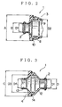
- a grommet 1 for a vehicle door is formed of elastomer which has characteristics similar to rubber in flexibility and strength, etc. , and is in a hollow tubular shape having an intermediate part 2 and two engaging parts 3, 4 at opposite ends of the intermediate part 2.
- the grommet 1 is attached to a chassis panel 5 and a door panel 6 enabling a wire harness 7 arranged therebetween to be protected from water and dust.
- the wire harness 7 can be protected by the grommet 1.
- the chassis panel 5 and the door panel 6 constitute bodies to be fitted mentioned in the claim.
- the intermediate part 2 is formed in a hollow tubular shape, and the wire harness 7 is adapted to pass through the intermediate part 2. Because the intermediate part 2 is formed in a bellows shape, the grommet can easily follow opening and closing movements of the vehicle door by expansion and contraction of the intermediate part. Opposite end portions of the intermediate part 2 are formed in an annular shape having a same inner diameter as threads projecting inwardly in a middle part of the intermediate part 2. The engaging parts 3, 4 are integrally continued from the opposite end portions. These opposite end portions are formed rectilinearly. In the present embodiment, the inner diameter of the opposite end portions of the intermediate part 2 is D1, as shown in Figs. 2 and 3. Preferably, the wire harness 7 is held in tight fit inside the intermediate part 2.
- the engaging part 3 includes a large diameter tubular portion 8 which is continued from the intermediate part 2 and adapted to be engaged with a hole in the chassis panel 5 which is not shown, and a funnel shaped tubular portion 9 which is in a substantially funnel shape in cross section and continued from the large diameter tubular portion 8 inside of the chassis panel 5.
- the engaging part 3 is so designed as to guide out the wire harness 7 to the chassis side.
- the large diameter tubular portion 8 has an inner diameter D2 which is larger than the inner diameter D1 of the intermediate part 2 (D2>D1) .
- the large diameter tubular portion 8 is provided with an annular groove 10 around its outer circumference to be engaged with the above mentioned hole in the chassis panel 5.
- the funnel shaped tubular portion 9 is provided with a slit 11.
- the engaging part 4 includes a large diameter tubular portion 12 which is continued from the intermediate part 2 and adapted to be engaged with a hole in the door panel 6 which is not shown, and a small diameter tubular portion 13 which is smaller in diameter than the large diameter tubular portion 12 and extends rectilinearly.
- the large diameter tubular portion 12 has an inner diameter D3 which is larger than the inner diameter D1 of the intermediate part 2 (D3>D1), and is provided with an annular groove 14 around its outer circumference to be engaged with the above mentioned hole in the door panel 6.
- the large diameter tubular portion 12 is formed in such a manner that the inner diameter D3 is less than five times as large as the inner diameter D1 of the intermediate part 2 for convenience of molding.
- the inner diameter D3 is equal to the inner diameter D2.
- An inner diameter D4 of the small diameter tubular portion 13 is set to be slightly larger than the inner diameter D1 of the intermediate part 2 and adequately smaller than the inner diameter D3.
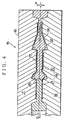
- the grommet 1 having the above described structure is formed by injection molding by means of a metal mold 15 as shown in Fig. 4.
- the metal mold 15 has at least one cavity part 16 which is composed of molds 17, 18 and a core 19.
- the molds 17, 18 are adapted to form an outer surface of the grommet 1, while the core 19 is adapted to form an inner surface of the grommet 1.
- the core 19 consists of a fixed part 20 and a movable part 21.
- a molding cavity 22 is formed in the cavity part 16, into which molten elastomer (thermoplastic elastomer) is injected.
- the molds 17, 18 are opened in directions of arrows P, and the movable part 21 of the core 19 slides in a direction of an arrow Q.
- the grommet 1 On the fixed part 20 of the core 19, there remains the grommet 1 which has been thus molded.
- the grommet 1 is air blown from inside of the intermediate part 2 (the intermediate part 2 is inf lated by means of an air inflator) to enlarge the inner diameter of the intermediate part 2.
- the grommet 1 as shown in Fig. 1 can be obtained by removing it from the fixed part 20 in the direction of the arrow Q.
- an area 23 contributes to forming of the intermediate part 2
- areas 24, 25 contribute to forming of the engaging parts 3, 4 respectively.
- the grommet 1 which has been formed through the above described molding process has been subjected to following tests according to a permanent extension test prescribed in JIS K 6301.
- Rabaron (black) (trade name) was employed as the thermoplastic elastomer.
- the grommet 1 according to the present invention has such effects that it is light weight and can be recycled. Further, since the vulcanizing process is not required, productivity will be enhanced Still further, because the grommet is produced by injection molding, the molding process can be conducted much faster and the productivity can be enhanced the more. Needless to say, dimensional accuracy of the inner surface of the grommet 1 can be stabilized thereby contributing to improvement of the productivity.
- thermoplastic elastomer olefin elastomer can be also employed besides the above mentioned rabaron (black) which is stylene elastomer.
Landscapes
- Engineering & Computer Science (AREA)
- Mechanical Engineering (AREA)
- Installation Of Indoor Wiring (AREA)
- Insulating Bodies (AREA)
Applications Claiming Priority (2)
| Application Number | Priority Date | Filing Date | Title |
|---|---|---|---|
| JP2000155238A JP2001339827A (ja) | 2000-05-25 | 2000-05-25 | グロメットの製造方法及びグロメット |
| JP2000155238 | 2000-05-25 |
Publications (2)
| Publication Number | Publication Date |
|---|---|
| EP1158637A1 EP1158637A1 (en) | 2001-11-28 |
| EP1158637B1 true EP1158637B1 (en) | 2004-01-14 |
Family
ID=18660210
Family Applications (1)
| Application Number | Title | Priority Date | Filing Date |
|---|---|---|---|
| EP01112735A Expired - Lifetime EP1158637B1 (en) | 2000-05-25 | 2001-05-25 | Grommet and method of producing the same |
Country Status (4)
| Country | Link |
|---|---|
| US (1) | US6737583B2 (enExample) |
| EP (1) | EP1158637B1 (enExample) |
| JP (1) | JP2001339827A (enExample) |
| DE (1) | DE60101760T2 (enExample) |
Families Citing this family (21)
| Publication number | Priority date | Publication date | Assignee | Title |
|---|---|---|---|---|
| WO2003081440A1 (en) | 2002-03-21 | 2003-10-02 | Snapp Robert F | Method and system for storing and retrieving data using hash-accessed multiple data stores |
| JP4036135B2 (ja) * | 2003-04-18 | 2008-01-23 | 住友電装株式会社 | グロメット |
| FR2864360B1 (fr) * | 2003-12-22 | 2008-09-26 | Cf Gomma Spa | Dispositif de connexion pour le passage et la protection de cables electriques, ou analogues, et son procede de fabrication |
| FR2867621B1 (fr) * | 2004-03-10 | 2006-06-02 | Joint Francais | Fourreau pour faisceau electrique monte entre une caisse et un ouvrant de vehicule a moteur, et son procede de fabrication |
| US6995317B1 (en) * | 2004-03-11 | 2006-02-07 | Excello Engineered Systems, Llc | Double wire pass through seal with grommets |
| FR2883109A1 (fr) * | 2004-11-03 | 2006-09-15 | Cf Gomma Spa | Dispositif de connexion a fixation par enclipsage pour le passage et la protection de cables electriques, ou analogues, et son procede de fabrication |
| FR2881702A1 (fr) * | 2005-10-27 | 2006-08-11 | Rz Engineering Soc Par Actions | Enveloppe a soufflets helicoidaux pour proteger des cables |
| FR2891410B1 (fr) * | 2005-10-27 | 2007-12-21 | Cf Gomma S P A | Procede de fabrication d'un dispositif de connexion a fixation par enclipsage pour le passage et la protection de cables electriques, ou analogues |
| JP4933854B2 (ja) * | 2006-07-20 | 2012-05-16 | 住友電装株式会社 | グロメット及び該グロメットの成形方法 |
| DE102006042663A1 (de) * | 2006-09-12 | 2008-03-27 | Robert Bosch Gmbh | Befestigungseinrichtung für eine Leitung |
| DE102006050544B4 (de) | 2006-10-26 | 2008-09-11 | Bayerische Motoren Werke Aktiengesellschaft | Tülle zur Anordnung zwischen zwei Montageelementen zum geschützten Durchführen von Kabeln/Leitungen oder dergleichen sowie Verfahren zu deren Herstellung |
| US20090108146A1 (en) * | 2007-10-31 | 2009-04-30 | Svette Jr Joseph A | Low ergonomic grommet and method of making |
| US20100291782A1 (en) * | 2009-05-18 | 2010-11-18 | Wade Ryan C | Grommet for electrical connector and method of manufacturing the same |
| US8944718B2 (en) | 2010-09-23 | 2015-02-03 | C-Flex Bearing Co., Inc. | Clamping bushing |
| JP6424793B2 (ja) * | 2015-10-19 | 2018-11-21 | 住友電装株式会社 | グロメットおよびワイヤハーネス |
| JP2017158232A (ja) * | 2016-02-29 | 2017-09-07 | 住友電装株式会社 | 弾性管状体 |
| JP6613282B2 (ja) * | 2017-10-26 | 2019-11-27 | 矢崎総業株式会社 | グロメット及びグロメット組付方法 |
| US10525908B2 (en) * | 2018-05-17 | 2020-01-07 | Kiekert Ag | Motor vehicle latching system with cable duct |
| JP6854261B2 (ja) * | 2018-06-22 | 2021-04-07 | 矢崎総業株式会社 | グロメット |
| DE102021118919A1 (de) * | 2020-09-23 | 2022-03-24 | Illinois Tool Works Inc. | Tüllenvorrichtung |
| US11820208B1 (en) * | 2022-05-27 | 2023-11-21 | Honda Motor Co., Ltd. | Door water management system for vehicle door |
Family Cites Families (28)
| Publication number | Priority date | Publication date | Assignee | Title |
|---|---|---|---|---|
| EP0461641A2 (en) | 1990-06-13 | 1991-12-18 | Matrix Science Corporation | Compositions and methods for fabricating solvent resistant connectors |
| JPH0523353A (ja) | 1991-07-17 | 1993-02-02 | Mitsui Petrochem Ind Ltd | 保護矯正具 |
| US5170008A (en) | 1991-08-29 | 1992-12-08 | International Business Machines Corp. | External cable grommet for cable entry of EMI protected cabinets |
| DK0554479T3 (da) | 1992-02-04 | 1997-11-03 | Siemens Ag | Fremgangsmåde til regulering af tekniske processer med flere regulatorer |
| JPH0636604A (ja) | 1992-07-16 | 1994-02-10 | Mazda Motor Corp | 車両用ハーネスグロメット |
| JPH0634051A (ja) | 1992-07-18 | 1994-02-08 | Yuusan Gasket Kk | シリンダヘッドガスケット |
| US6265670B1 (en) * | 1993-03-18 | 2001-07-24 | The Whitaker Corporation | Grommet for plurality of cable exits of an enclosure |
| US5567916A (en) * | 1993-06-11 | 1996-10-22 | Siecor Corporation | Grommet |
| GB9313446D0 (en) | 1993-06-30 | 1993-08-11 | Raychem Ltd | Electrical harnessing article |
| JPH07215340A (ja) | 1994-01-28 | 1995-08-15 | Mitsubishi Chem Corp | 回収可能型合成樹脂パレット |
| JPH087685A (ja) | 1994-06-17 | 1996-01-12 | Mitsubishi Chem Mkv Co | グロメット |
| JP3291674B2 (ja) | 1995-06-06 | 2002-06-10 | 住友電装株式会社 | ガスシール用のグロメット |
| JPH09117039A (ja) | 1995-10-17 | 1997-05-02 | Sumitomo Wiring Syst Ltd | グロメット及びワイヤハーネスへのグロメットの装着構造 |
| JPH09120728A (ja) | 1995-10-25 | 1997-05-06 | Sumitomo Wiring Syst Ltd | グロメット |
| JP3175579B2 (ja) | 1996-03-11 | 2001-06-11 | 住友電装株式会社 | 自動車ドア用ワイヤハーネスの取付構造および取付方法 |
| JPH09289725A (ja) | 1996-04-22 | 1997-11-04 | Sumitomo Wiring Syst Ltd | グロメット |
| JP3106958B2 (ja) | 1996-05-28 | 2000-11-06 | 住友電装株式会社 | グロメット |
| JP3384256B2 (ja) | 1996-08-01 | 2003-03-10 | 住友電装株式会社 | グロメットおよび該グロメットの製造方法 |
| JPH10145944A (ja) | 1996-11-13 | 1998-05-29 | Sumitomo Wiring Syst Ltd | グロメットおよび該グロメットの取付構造 |
| JPH10246333A (ja) | 1997-03-03 | 1998-09-14 | Sumitomo Wiring Syst Ltd | グロメット |
| JPH10297389A (ja) | 1997-04-23 | 1998-11-10 | Yazaki Corp | 蛇腹付グロメット |
| JP3271555B2 (ja) * | 1997-06-04 | 2002-04-02 | 住友電装株式会社 | グロメット |
| JPH1141756A (ja) | 1997-07-17 | 1999-02-12 | Sumitomo Wiring Syst Ltd | グロメット |
| JPH1189053A (ja) | 1997-09-02 | 1999-03-30 | Sumitomo Wiring Syst Ltd | グロメット |
| JPH1189055A (ja) | 1997-09-10 | 1999-03-30 | Sumitomo Wiring Syst Ltd | グロメット、該グロメットのガラス面への接着方法および接着構造 |
| JPH11130068A (ja) | 1997-10-24 | 1999-05-18 | Aron Kasei Co Ltd | 合成樹脂製パレット |
| JP3185728B2 (ja) | 1997-11-06 | 2001-07-11 | 住友電装株式会社 | グロメット |
| JPH11167834A (ja) | 1997-12-05 | 1999-06-22 | Sumitomo Wiring Syst Ltd | グロメットの製造方法及び該方法により製造されたグロメット |
-
2000
- 2000-05-25 JP JP2000155238A patent/JP2001339827A/ja active Pending
-
2001
- 2001-05-24 US US09/863,892 patent/US6737583B2/en not_active Expired - Lifetime
- 2001-05-25 EP EP01112735A patent/EP1158637B1/en not_active Expired - Lifetime
- 2001-05-25 DE DE60101760T patent/DE60101760T2/de not_active Expired - Fee Related
Also Published As
| Publication number | Publication date |
|---|---|
| US6737583B2 (en) | 2004-05-18 |
| US20020004967A1 (en) | 2002-01-17 |
| EP1158637A1 (en) | 2001-11-28 |
| DE60101760T2 (de) | 2004-12-02 |
| JP2001339827A (ja) | 2001-12-07 |
| DE60101760D1 (de) | 2004-02-19 |
Similar Documents
| Publication | Publication Date | Title |
|---|---|---|
| EP1158637B1 (en) | Grommet and method of producing the same | |
| US5659924A (en) | Grommet with flexible sealing passage | |
| EP0822121B1 (en) | A noise-preventive grommet and a manufacturing process of the same | |
| KR20040062692A (ko) | 플랩 조립체를 구비한 차단장치 | |
| DE60106795T2 (de) | Hohlförmiger blasgeformter Gegenstand; Herstellungsverfahren für solch einen Artikel und Vorrichtung zu dessen Herstellung | |
| US6338499B2 (en) | Car interior part with air bag cover portion | |
| US7404996B2 (en) | Two-shot polymeric component with attachment feature and method of producing same | |
| US8378238B2 (en) | Protective sleeve to be arranged between two assembly elements for passing through cables/lines or the like in protective fashion and method for its production | |
| JP4482439B2 (ja) | 樹脂成形品 | |
| JPH06218799A (ja) | ハウジングパネルの製造方法 | |
| JP3474762B2 (ja) | 樹脂製ダクト | |
| JP2791857B2 (ja) | ベローズ製造用金型装置 | |
| DE102007023075A1 (de) | Kunststoff-Innenausstattungsteil aus Hartkunststoff mit einer Abdeckung für einen Airbag eines Airbag-Moduls und Verfahren zur Herstellung eines solchen Kunststoff-Innenausstattungsteils | |
| US6464577B2 (en) | Process for manufacturing a register for ventilating air | |
| JP2767905B2 (ja) | スピーカ装置 | |
| JPH01110116A (ja) | 中空成形品の成形装置 | |
| KR100339086B1 (ko) | 차량용 웨더스트립 및 그 제조방법 | |
| JPH06155501A (ja) | 樹脂製管状体の製造方法 | |
| JP2002103411A (ja) | 樹脂製芯材内蔵ウェザーストリップを製造する方法 | |
| JPH08251768A (ja) | グロメット | |
| JP2000280756A (ja) | ウェザーストリップ取付構造及びウェザーストリップ | |
| JPH07329132A (ja) | インストルメントパネル成形時の変形防止方法 | |
| KR0116890Y1 (ko) | 자동차용 사이드 트림 결합구조 | |
| KR100346281B1 (ko) | 차량용 범퍼가드의 제조방법 | |
| JP3325540B2 (ja) | 曲管用プロテクター |
Legal Events
| Date | Code | Title | Description |
|---|---|---|---|
| PUAI | Public reference made under article 153(3) epc to a published international application that has entered the european phase |
Free format text: ORIGINAL CODE: 0009012 |
|
| AK | Designated contracting states |
Kind code of ref document: A1 Designated state(s): DE FR GB IT SE Kind code of ref document: A1 Designated state(s): AT BE CH CY DE DK ES FI FR GB GR IE IT LI LU MC NL PT SE TR |
|
| AX | Request for extension of the european patent |
Free format text: AL;LT;LV;MK;RO;SI |
|
| 17P | Request for examination filed |
Effective date: 20020528 |
|
| AKX | Designation fees paid |
Free format text: DE FR GB IT SE |
|
| 17Q | First examination report despatched |
Effective date: 20020912 |
|
| GRAP | Despatch of communication of intention to grant a patent |
Free format text: ORIGINAL CODE: EPIDOSNIGR1 |
|
| GRAS | Grant fee paid |
Free format text: ORIGINAL CODE: EPIDOSNIGR3 |
|
| GRAA | (expected) grant |
Free format text: ORIGINAL CODE: 0009210 |
|
| AK | Designated contracting states |
Kind code of ref document: B1 Designated state(s): DE FR GB IT SE |
|
| REG | Reference to a national code |
Ref country code: GB Ref legal event code: FG4D |
|
| REF | Corresponds to: |
Ref document number: 60101760 Country of ref document: DE Date of ref document: 20040219 Kind code of ref document: P |
|
| REG | Reference to a national code |
Ref country code: SE Ref legal event code: TRGR |
|
| ET | Fr: translation filed | ||
| PLBE | No opposition filed within time limit |
Free format text: ORIGINAL CODE: 0009261 |
|
| STAA | Information on the status of an ep patent application or granted ep patent |
Free format text: STATUS: NO OPPOSITION FILED WITHIN TIME LIMIT |
|
| 26N | No opposition filed |
Effective date: 20041015 |
|
| PGFP | Annual fee paid to national office [announced via postgrant information from national office to epo] |
Ref country code: DE Payment date: 20080602 Year of fee payment: 8 |
|
| PGFP | Annual fee paid to national office [announced via postgrant information from national office to epo] |
Ref country code: IT Payment date: 20080524 Year of fee payment: 8 |
|
| PGFP | Annual fee paid to national office [announced via postgrant information from national office to epo] |
Ref country code: SE Payment date: 20080523 Year of fee payment: 8 |
|
| PGFP | Annual fee paid to national office [announced via postgrant information from national office to epo] |
Ref country code: GB Payment date: 20080522 Year of fee payment: 8 |
|
| GBPC | Gb: european patent ceased through non-payment of renewal fee |
Effective date: 20090525 |
|
| REG | Reference to a national code |
Ref country code: FR Ref legal event code: ST Effective date: 20100129 |
|
| PG25 | Lapsed in a contracting state [announced via postgrant information from national office to epo] |
Ref country code: FR Free format text: LAPSE BECAUSE OF NON-PAYMENT OF DUE FEES Effective date: 20090602 |
|
| PGFP | Annual fee paid to national office [announced via postgrant information from national office to epo] |
Ref country code: FR Payment date: 20080519 Year of fee payment: 8 |
|
| PG25 | Lapsed in a contracting state [announced via postgrant information from national office to epo] |
Ref country code: GB Free format text: LAPSE BECAUSE OF NON-PAYMENT OF DUE FEES Effective date: 20090525 |
|
| PG25 | Lapsed in a contracting state [announced via postgrant information from national office to epo] |
Ref country code: DE Free format text: LAPSE BECAUSE OF NON-PAYMENT OF DUE FEES Effective date: 20091201 |
|
| PG25 | Lapsed in a contracting state [announced via postgrant information from national office to epo] |
Ref country code: IT Free format text: LAPSE BECAUSE OF NON-PAYMENT OF DUE FEES Effective date: 20090525 |
|
| PG25 | Lapsed in a contracting state [announced via postgrant information from national office to epo] |
Ref country code: SE Free format text: LAPSE BECAUSE OF NON-PAYMENT OF DUE FEES Effective date: 20090526 |