EP1138588B1 - A motorcycle frame - Google Patents
A motorcycle frame Download PDFInfo
- Publication number
- EP1138588B1 EP1138588B1 EP01107596A EP01107596A EP1138588B1 EP 1138588 B1 EP1138588 B1 EP 1138588B1 EP 01107596 A EP01107596 A EP 01107596A EP 01107596 A EP01107596 A EP 01107596A EP 1138588 B1 EP1138588 B1 EP 1138588B1
- Authority
- EP
- European Patent Office
- Prior art keywords
- section
- frame
- vehicle
- engine
- pipe
- Prior art date
- Legal status (The legal status is an assumption and is not a legal conclusion. Google has not performed a legal analysis and makes no representation as to the accuracy of the status listed.)
- Expired - Lifetime
Links
Images


Classifications
-
- B—PERFORMING OPERATIONS; TRANSPORTING
- B62—LAND VEHICLES FOR TRAVELLING OTHERWISE THAN ON RAILS
- B62K—CYCLES; CYCLE FRAMES; CYCLE STEERING DEVICES; RIDER-OPERATED TERMINAL CONTROLS SPECIALLY ADAPTED FOR CYCLES; CYCLE AXLE SUSPENSIONS; CYCLE SIDE-CARS, FORECARS, OR THE LIKE
- B62K11/00—Motorcycles, engine-assisted cycles or motor scooters with one or two wheels
- B62K11/02—Frames
- B62K11/04—Frames characterised by the engine being between front and rear wheels
-
- F—MECHANICAL ENGINEERING; LIGHTING; HEATING; WEAPONS; BLASTING
- F02—COMBUSTION ENGINES; HOT-GAS OR COMBUSTION-PRODUCT ENGINE PLANTS
- F02F—CYLINDERS, PISTONS OR CASINGS, FOR COMBUSTION ENGINES; ARRANGEMENTS OF SEALINGS IN COMBUSTION ENGINES
- F02F7/00—Casings, e.g. crankcases
- F02F7/006—Camshaft or pushrod housings
Definitions
- This invention relates to a motorcycle frame of the kind defined in the preamble of claim 1.
- EP-A-0 447 899 discloses a motorcycle frame of this kind comprising a down frame strengthened by means of a plurality of internal plates.
- An object of the present application is to provide a motorcycle frame that is formed having a cross sectional shape conforming to required stress distribution to reduce weight, and which can be made easily.
- the down frame of the present invention has a rib formed on an inner surface of a front side section, which means that the front side of the down frame having maximum stress sections can be made especially rigid, while other sections can be made comparatively thin, with the result that it can be formed having a cross sectional shape conforming to actual stress distribution, contributing to reduction in the overall weight of the vehicle frame.
- the pipe having this type of angular cross section has a rib integrally formed on an inner surface and a previously extruded angular cross section pipe can be easily obtained using a swaging process, and at this time it is also possible to form an asymmetrical shape having only a rear side surface section tapered.
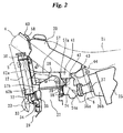
- a motorcycle frame 1 has a cradle shape and supports a water cooled 4-cycle engine 2, and comprises a pair of left and right mainframes 4 extending from a headpipe 3 over the engine 2 to the rear of the vehicle, a down tube or frame 5 extending diagonally downwards from the head pipe 3 along a vehicle center line in front of the engine 2, a pair of left and right pivot plates 6 connecting to rear ends of respective left and right main frames 4 and arranged in a vertical direction to the rear of the engine 2, and a pair of left and right lower frames 7 passing underneath the engine 2 for connecting the down tube 5 and the lower ends of each of the pivot plates 6.
- a pair of left and right seat rails 8 extend rearwards from upper end sections of the pivot plates 6, and rear end sections of the seat rails 8 and interstitial sections of the pivot plates are connected by a sloping rear caliper 9.
- a pair of left and right front forks 11 steered by the handle 10 are rotatably supported on the headpipe 3 via a top bridge 12 and a bottom bridge 13.
- Reference numeral 14 is a front wheel.
- Front ends of rear swing arms 16 are swingably supported between interstitial sections of the left and right pivot plates 6 using a pivot shaft 15, and a rear wheel is supported on rear ends of the rear swingarms 16. Also, a rear cushion 19 is attached between a link 18 provided on a front section of the rear swing arms and a rear cross member, that will be described later, provided on an upper end of the pivot plates, constituting a rear wheel suspension.
- reference numeral 20 is a fuel tank supported between left and right main frames 4, 21 is a seat supported on the left and right seat rails 8, 22 is a radiator, 23 is an exhaust pipe, 24 is a carburetor, 25 is an air cleaner and 26 is a muffler.
- the engine 2 is a water cooled 4-cycle engine, with a cylinder head 27 provided substantially upright, and a cylinder head cover 28 substantially forming a triangle viewed from the side, with a rear side of the cylinder head cover 28 fitted into an inner side of the main frames 4.
- An exhaust passageway 35 is provided in a central front section of the cylinder head 27, and an exhaust pipe 23 is connected to the exhaust passageway.
- the radiator 22 is supported on both of the pair of left and right down tubes 5 (refer to Fig 5), and a return water side water hose 31 is piped between an upper tank 30 of the radiator and a cylinder head tank 28.
- a sending water side hose 33 extends from a lower tank 32, and connects to a crankcase 29 side.
- a carburetor 24 is connected to an intake port provided on a rear surface side of the cylinder head 27, and an intake upstream side of the carburetor 24 is connected to an air cleaner 25 via a connecting tube 36.
- the connecting tube 36 is arranged so that a section in the vicinity of a joining part of a rear end of the main frame 4, at an upper part of the pivot plate 6 of the main frame 4, is traversed when viewed from the side.
- the air cleaner 25 has a front section 37 removably provided on a front surface to connect with a rear end of the connecting tube 36, and in this way the maintainability of the air cleaner having the connecting tube 36 arranged like this is improved.
- a fuel tank 20 is supported by being attached, using bolts or the like, to a boss 58 for positioning a front end section on an upper part of the main frame using a bracket 40, and a rear end section is supported on a rear cross member, to be described later, provided between upper end sections of the left and right pivot plates 6.
- a sump-like section 41 projecting downwards is provided in a rear lower part of the fuel tank 20, and a fuel cock 42 is provided in a lower part of the sump-like section.
- the sump-like section 41 is arranged projecting to the rear of the cylinder head 27 and cylinder head cover 28 projecting above the 4-cycle engine 2, and into the inside of a sump-like space 57a formed in front of the rear cross member 43, and has a height that overlaps the cylinder head cover 28 in the longitudinal direction of the vehicle, and is positioned overlapping an upper part of the carburetor 24 when viewed from the side.
- the position of the fuel cock 42 provided below the sump-like section 41 is such that a lower end protrudes slightly lower than a lower edge of the main frame 4 when viewed from the side, and the sump-like section 41 is positioned overlapping the main frame 4. Also, as is clear from Fig. 3, the sump-like section 41 links to the carburetor 24 in a widthwise direction of the vehicle.
- an upper section is supported by the mainframe 4, a front side is supported by a down tube lower section, the lower side is supported by a central section of the lower frame 7, and a rear section has a crankcase 29 supported by the pivot plates 6 using a pivot shaft 15.
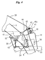
- the upper section is supported on a lower surface of the main frame 4, via a hanger bracket 39, by a support section 38 provided on a rear section of the cylinder head 27, as shown in Fig. 2 and Fig. 4.
- Fig. 5 shows the down tube 5 and components around the down tube 5, for the layout of the radiators 22, from the front of the vehicle.
- the radiators 22 are provided on the left and right, with respective upper tanks 30 being connected by a return water hose 31, and connected to a water jacket outlet on the cylinder head cover 28 side by a joint pipe 31a.
- sending water hoses 33 from each of lower tanks 32 extend to the center of the vehicle, are connected to a joint hose 34 traversing in a lateral direction across the rear of a tapered section 62b of the down tube 5, and are also connected to a water pump 49 provided on the right side of the crankcase by a joint section 34a provided on the right side of the joint hose 34.
- An exhaust pipe 23 also passes behind the tapered section 62b, slopes downwards jutting out to the right side of the vehicle, passes below the right side radiator 22 and extends to the rear.
- Fig. 6 shows these components from the rear of the vehicle.
- a carburetor 24 is arranged at a position below the vicinity of the rear cross member 43 and approaching the left side of the vehicle, a sump-like section 41 and a fuel cock 42 provided underneath the bottom of the sump-like section 41 are positioned on the right side of the carburetor 24, and a fuel tube 42a extending downwards from the fuel cock 42 is connected to a float chamber 24a of the carburetor 24.
- the height of the fuel cock 42 is slightly higher than the float chamber 24a.
- a rear cushion 19 is positioned to the rear of these components, and in the vicinity of the center of the vehicle, and the fuel cock 42 is positioned so as to overlap to the front of a reserve tank 19a aligned with the rear cushion 19.
- An exhaust pipe is also arranged passing below each of the fuel cock 42 and the reserve tank 19a. A front part of the exhaust pipe 23 juts out at a sloping right side from the front of the cylinder head 27 and then curves again towards the inside of the vehicle (refer to Fig.
- the main frame 4 has a member formed by extruding an aluminum alloy so as to have a longitudinal rectangular cross section, with a front end being welded to the headpipe 3 and a rear end being welded to an upper part of the pivot plate 6.
- the down tube 5 is formed from an angular pipe of aluminum alloy or the like, with a rear side wall of a smaller section being formed into a tapered shape using a swaging process, a rear wall upper section and lower walls of each of the middle parts of the left and right main frames 4 being horizontal when viewed from the side, and connection being reinforced by a tension pipe 50 having an arched shape pointing towards the front when viewed in plan.
- a front end of the tension pipe 50 is linked to the down tube 5 by a gusset 51, and an attachment stay of a hanger bracket 39 is provided on a rear end of the tension pipe 50 and a welded section of the main frame 4.
- a lower part of the down tube 5 is welded to a front end of a lower frame 7 formed from an angular aluminum alloy pipe divided into left and right sections, via a joint member 53.
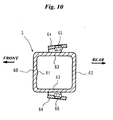
- Fig. 10 is a cross section of the down tube 5, and of the four walls, a rib 61 for linking in a length direction is integrally formed on an inner middle surface of the front wall 60.
- a rear wall 62 has a lower half side forming a tapered section 62b, that will be described later, gradually becoming thinner towards the bottom.
- the rear wall upper section 62a of the upper half side is formed into a straight section.
- L-shaped radiator attachment sections 64 are welded to the outside of each of the left and right side walls 63, weld nuts 65 are provided on the attachment sections 64, and the left and right radiators 2 are bolt fastened.
- the tapered section 62b is only provided on the rear wall 62, and a space 57b is formed behind the tapered section 62b, and between the cylinder head 27 and the front of the cylinder head cover 28.
- Other sections namely an upper rear wall 62a, a front wall 60 and left and right side walls 63 are not tapered, and are all straight walls.
- the down tube 5 has an asymmetrical shape when viewed from the side.
- an angular cross section pipe is previously extruded with a specified cross section with an integral rib 61, and by performing a swaging process to compress the pipe only from 4 orthogonal directions, it is possible to form only specific walls to a tapered shape of only a required length.
- This type of swaging process is well known, and by doing this it is possible to arbitrarily thicken the inner cross-sectional wall at one part, and it is also easy to form the rib 61 of this embodiment.
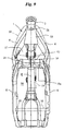
- the pivot plates 6 are plate members constructed of aluminum alloy or cast metal, and upper ends form upwardly extending sections 54 projecting further up than the rear end of the main frame 4, with these sections sloping inwardly respectively to the left and right (refer to Fig. 8 and Fig. 9). Indentations are formed in opposite inner side surfaces of the left and right upwardly extending sections 54, and both ends of the rear cross member 43 are fitted into these indentations and welded. Also, pivot receiving sections are provided at lower side positions in the middle of the left and right pivot plates 6, and both ends of a pivot shaft 15 are supported in these receiving sections.
- the rear cross member 43 is a hollow member obtained by casting or molding aluminum alloy or the like, and an upper surface 44 of the rear cross member constitutes a support section on which a rear end 45 of the fuel tank is placed and supported. Also, a cushion bracket 46 protruding in a bifurcated shape towards the rear is integrally formed in a central section, and an upper end of the rear cushion 19 is rotatably supported on the cushion bracket 46. This cushion bracket 46 is slightly offset from the center of the vehicle, but is provided at a position where the offset is minimum. Attachment sections for the seat rail 8 are formed on an upper section of the cushion bracket 46.
- a space 56 (Fig. 6) formed between the underneath of the rear cross member 43, the left and right pivot plates 6 and a lower pivot shaft 15 forms an extremely large continuous space, and the rear cushion 19, exhaust pipe 23 and connecting tube 36 are all arranged in this space, as shown in Fig. 6.
- a large continuous fuel tank storage space 57 (Fig. 8) is also formed further forward than the rear cross member 43, higher than the tension pipe 50 and further to the rear than the head pipe 3, and in part of this space a cylinder rear space 57a is formed to the rear side of the cylinder head cover 28 of the engine 2 (Fig. 3).
- Reference numeral 58 in Fig. 8 and Fig. 9 is an attachment boss for the bracket 40 integrally formed with the head pipe 3, and 59 is a cross member integrally formed with a rear section of the head pipe 3 and extending rearwards, securing contact sections of the left and right main frames 4.
- reference numeral 53a in Fig. 7 is an engine support stay provided on the joint member 53, while reference numeral 7a in Fig. 7 is an engine support stay provided on the lower frame 7.
- the rib 61 is integrally provided on an inner surface of a front wall 60 of the down tube 5, which means that it is possible to increase the rigidity of only the front wall 60, being the most stressed section, and it is possible to make the other walls 62 and 63 thinner than the rib 61. Accordingly, it is possible to realize an overall reduction in weight while ensuring the required rigidity.
- a lower end of the rear wall 62 of the down tube 5 is made into a tapered section 62b, and so by providing the rib 61 on the front wall 60 and providing the tapered section 62b on the rear wall 62 constituting an opposite wall it is possible arbitrarily balance the rigidity of the down tube 5 and the vehicle frame 1, which is also advantageous to vehicle layout.
- the space 57b is formed between this tapered section 62b and each of the side sections of the cylinder head 27 and the cylinder head cover 28, it is possible to arrange the joint hose 34, being a water hose for the radiator 22, and the exhaust pipe 23 using this space 57b, and as a result it becomes possible to reduce the overall length of the vehicle and to make the vehicle more compact.
- the angular cross section pipe subjected to this type of tapering process or having thickness deviation can be easily formed by, after extruding an angular pipe as in this embodiment, applying a special swaging process to compress the extruded angular pipe from only four orthogonal directions.
- a rear wall upper section 62a is a straight section, which means that with this straight section as a joining wall welding processing can be performed easily in the case of welding the tension plate 51.
- the present invention is not limited to the above described embodiment, and various adaptations ore possible.
- the front wheel can be brought closer to the down tube 5 side, which means that there is increased freedom with respect to selecting the position of the headpipe 3, and there is increased freedom with respect to the vehicle geometry.
Landscapes
- Engineering & Computer Science (AREA)
- Mechanical Engineering (AREA)
- Automatic Cycles, And Cycles In General (AREA)
- Motorcycle And Bicycle Frame (AREA)
Applications Claiming Priority (2)
| Application Number | Priority Date | Filing Date | Title |
|---|---|---|---|
| JP2000096804 | 2000-03-31 | ||
| JP2000096804A JP3766580B2 (ja) | 2000-03-31 | 2000-03-31 | 自動2輪車用車体フレームの製法 |
Publications (3)
| Publication Number | Publication Date |
|---|---|
| EP1138588A2 EP1138588A2 (en) | 2001-10-04 |
| EP1138588A3 EP1138588A3 (en) | 2004-08-11 |
| EP1138588B1 true EP1138588B1 (en) | 2006-06-07 |
Family
ID=18611519
Family Applications (1)
| Application Number | Title | Priority Date | Filing Date |
|---|---|---|---|
| EP01107596A Expired - Lifetime EP1138588B1 (en) | 2000-03-31 | 2001-03-27 | A motorcycle frame |
Country Status (5)
| Country | Link |
|---|---|
| US (1) | US6695089B2 (enExample) |
| EP (1) | EP1138588B1 (enExample) |
| JP (1) | JP3766580B2 (enExample) |
| AT (1) | ATE328782T1 (enExample) |
| ES (1) | ES2260111T3 (enExample) |
Families Citing this family (56)
| Publication number | Priority date | Publication date | Assignee | Title |
|---|---|---|---|---|
| JP2001247073A (ja) * | 2000-03-02 | 2001-09-11 | Honda Motor Co Ltd | 車体フレーム構造 |
| JP4368596B2 (ja) * | 2003-02-26 | 2009-11-18 | 本田技研工業株式会社 | 自動2輪車の車体構造 |
| JP4233022B2 (ja) * | 2003-02-27 | 2009-03-04 | 本田技研工業株式会社 | 自動二輪車のフレーム構造 |
| US7650959B2 (en) | 2003-04-02 | 2010-01-26 | Yamaha Hatsudoki Kabushiki Kaisha | Frame arrangement for off-road vehicle |
| US7506712B2 (en) * | 2003-04-02 | 2009-03-24 | Yamaha Hatsudoki Kabushiki Kaisha | Off road vehicle with air intake system |
| US7367417B2 (en) | 2003-04-02 | 2008-05-06 | Yamaha Hatsudoki Kabushiki Kaisha | Floor arrangement for off-road vehicle |
| US7147075B2 (en) * | 2003-04-02 | 2006-12-12 | Yamaha Hatsudoki Kabushiki Kaisha | Engine arrangement for off-road vehicle |
| US7438147B2 (en) | 2003-04-02 | 2008-10-21 | Yamaha Hatsudoki Kabushiki Kaisha | Transmission for off-road vehicle |
| US7287619B2 (en) | 2003-04-02 | 2007-10-30 | Yamaha Hatsudoki Kabushiki Kaisha | Air intake system for off-road vehicle |
| US7510199B2 (en) | 2003-04-02 | 2009-03-31 | Yamaha Hatsudoki Kabushiki Kaisha | Off-road vehicle with wheel suspension |
| US7357211B2 (en) | 2003-04-02 | 2008-04-15 | Yamaha Hatsudoki Kabushiki Kaisha | Steering system for off-road vehicle |
| JP2007022097A (ja) * | 2003-08-20 | 2007-02-01 | Yamaha Motor Co Ltd | 鞍乗り型車両 |
| JP4163585B2 (ja) | 2003-09-30 | 2008-10-08 | 本田技研工業株式会社 | 自動二輪車の車体構造 |
| JP2005138820A (ja) * | 2003-10-16 | 2005-06-02 | Yamaha Motor Co Ltd | 鞍乗り型車両 |
| JP2005280507A (ja) * | 2004-03-30 | 2005-10-13 | Yamaha Motor Co Ltd | 自動二輪車のエンジン支持装置 |
| CN100379639C (zh) * | 2004-03-31 | 2008-04-09 | 本田技研工业株式会社 | 全地形车辆 |
| JP2006015837A (ja) * | 2004-06-30 | 2006-01-19 | Yamaha Motor Co Ltd | 自動二輪車 |
| US20060032686A1 (en) * | 2004-08-12 | 2006-02-16 | Norman Berg | Spindle for snowmobile suspension |
| JP2006056355A (ja) * | 2004-08-19 | 2006-03-02 | Honda Motor Co Ltd | 燃料電池車両における排出構造 |
| JP4731926B2 (ja) * | 2005-01-31 | 2011-07-27 | 川崎重工業株式会社 | 自動二輪車のフレーム |
| US7637345B2 (en) * | 2004-12-24 | 2009-12-29 | Kawasaki Jukogyo Kabushiki Kaisha | Frame of motorcycle and engine bracket |
| US7497455B2 (en) | 2005-01-28 | 2009-03-03 | Michael Kamalian | Carbon fiber motorcycle frame |
| JP4516497B2 (ja) * | 2005-03-02 | 2010-08-04 | 本田技研工業株式会社 | 自動二輪車の車体フレーム |
| JP4684715B2 (ja) * | 2005-04-01 | 2011-05-18 | 川崎重工業株式会社 | 車輌のシュラウド |
| JP4991159B2 (ja) * | 2006-01-31 | 2012-08-01 | 本田技研工業株式会社 | 自動二輪車の車体フレーム |
| JP4582035B2 (ja) * | 2006-03-27 | 2010-11-17 | 株式会社デンソー | 自動二輪車用熱交換器およびその製造方法 |
| JP2007308131A (ja) * | 2006-04-20 | 2007-11-29 | Denso Corp | 自動二輪車用熱交換器 |
| JP2008143511A (ja) * | 2006-11-15 | 2008-06-26 | Yamaha Motor Co Ltd | 車体フレームおよび車両 |
| JP2008222077A (ja) * | 2007-03-13 | 2008-09-25 | Yamaha Motor Co Ltd | 自動二輪車の車体フレーム,該車体フレームにエンジンを搭載するための組立方法,及び該車体フレームを備えた自動二輪車 |
| JP2008222010A (ja) * | 2007-03-13 | 2008-09-25 | Yamaha Motor Co Ltd | 車両 |
| JP2009090893A (ja) * | 2007-10-10 | 2009-04-30 | Yamaha Motor Co Ltd | 鞍乗型車両 |
| JP2009132355A (ja) * | 2007-10-30 | 2009-06-18 | Yamaha Motor Co Ltd | 鞍乗型車両のラジエータカバーおよびそれを備えた鞍乗型車両 |
| US7779951B1 (en) * | 2008-01-19 | 2010-08-24 | Victor Cabanas | Process for building the rear portion of a motorcycle |
| JP2009255626A (ja) * | 2008-04-14 | 2009-11-05 | Yamaha Motor Co Ltd | 自動二輪車 |
| JP2009255627A (ja) * | 2008-04-14 | 2009-11-05 | Yamaha Motor Co Ltd | 鞍乗型車両 |
| US20100018793A1 (en) * | 2008-07-24 | 2010-01-28 | Arnold David W | Saddle-type vehicles having dual l-shaped radiators |
| JP3154637U (ja) * | 2008-08-08 | 2009-10-22 | ヤマハ発動機株式会社 | 鞍乗り型車両 |
| US7980347B2 (en) * | 2008-10-21 | 2011-07-19 | Honda Motor Company, Ltd. | Motorcycles having frame with aperture passing flexible drive member and methods |
| JP5548499B2 (ja) * | 2010-03-30 | 2014-07-16 | 本田技研工業株式会社 | 鞍乗り型車両 |
| JP2011240774A (ja) * | 2010-05-17 | 2011-12-01 | Suzuki Motor Corp | 自動二輪車の車体フレーム |
| JP5618856B2 (ja) * | 2011-02-14 | 2014-11-05 | 本田技研工業株式会社 | 自動二輪車の車体フレーム |
| JP5675413B2 (ja) * | 2011-02-14 | 2015-02-25 | 本田技研工業株式会社 | 自動二輪車の車体フレーム |
| JP5853618B2 (ja) * | 2011-11-11 | 2016-02-09 | スズキ株式会社 | 鞍乗型車両のフレーム構造 |
| JP5690706B2 (ja) * | 2011-11-16 | 2015-03-25 | 本田技研工業株式会社 | 鞍乗型車両のラジエータ構造 |
| JP5661026B2 (ja) * | 2011-12-20 | 2015-01-28 | 本田技研工業株式会社 | 中空溶接組立フレーム構造 |
| JP5969232B2 (ja) * | 2012-03-22 | 2016-08-17 | 本田技研工業株式会社 | 鞍乗り型車両のラジエータホース配置構造 |
| FR2993212B1 (fr) * | 2012-07-13 | 2015-11-27 | Rdmo | Motocyclette a moteur a refroidissement liquide |
| JP6202516B2 (ja) * | 2013-01-31 | 2017-09-27 | 本田技研工業株式会社 | 鞍乗り型車両 |
| JP6140556B2 (ja) * | 2013-07-10 | 2017-05-31 | 本田技研工業株式会社 | 自動二輪車 |
| JP6126954B2 (ja) * | 2013-09-11 | 2017-05-10 | 本田技研工業株式会社 | 鞍乗型車両 |
| EP3067261B1 (en) * | 2013-11-07 | 2021-01-06 | Kawasaki Jukogyo Kabushiki Kaisha | Vehicle body frame structure of straddle-type vehicle |
| JP6223252B2 (ja) * | 2014-03-27 | 2017-11-01 | 本田技研工業株式会社 | 自動二輪車の車体フレーム構造 |
| JP2018086907A (ja) * | 2016-11-28 | 2018-06-07 | ヤマハ発動機株式会社 | 鞍乗型車両 |
| JP6815348B2 (ja) * | 2018-03-28 | 2021-01-20 | 本田技研工業株式会社 | 自動二輪車のサイドスタンドおよびサイドスタンドの製造方法 |
| US11117637B2 (en) | 2018-07-25 | 2021-09-14 | Harley-Davidson Motor Company Group, LLC | Motorcycle frame |
| JP6749979B2 (ja) * | 2018-09-27 | 2020-09-02 | 本田技研工業株式会社 | 鞍乗り型電動車両 |
Family Cites Families (20)
| Publication number | Priority date | Publication date | Assignee | Title |
|---|---|---|---|---|
| GB498696A (en) * | 1936-08-04 | 1939-01-12 | Audi Ag | Improvements in frames for motor cycles and methods of producing same |
| JPS5950938A (ja) * | 1982-09-14 | 1984-03-24 | Teruaki Yoshida | 自動二輪車用車体フレ−ムの製造方法 |
| JPS6094817A (ja) * | 1983-10-31 | 1985-05-28 | Yamaha Motor Co Ltd | 自動三輪車等のラジエ−タ装置 |
| JPS6229481A (ja) * | 1985-07-30 | 1987-02-07 | 本田技研工業株式会社 | 自動二輪車のブレ−キ冷却構造 |
| US4662645A (en) * | 1985-11-25 | 1987-05-05 | Wald Manufacturing Co., Inc. | Bicycle fork |
| US4809999A (en) * | 1986-03-04 | 1989-03-07 | Honda Giken Kogyo Kabushiki Kaisha | Tubular frame member |
| US4805716A (en) * | 1987-08-12 | 1989-02-21 | Honda Giken Kogyo Kabushiki Kaisha | Motorcycle body frame structure |
| JPH01226484A (ja) * | 1988-03-08 | 1989-09-11 | Suzuki Motor Co Ltd | オートバイのフレーム材 |
| JPH0274488A (ja) * | 1988-09-12 | 1990-03-14 | Suzuki Motor Co Ltd | 自動2輪車の車体フレーム |
| JP2951338B2 (ja) | 1989-09-29 | 1999-09-20 | ヤマハ発動機株式会社 | 自動二輪車の車体フレーム構造 |
| US5261504A (en) * | 1990-03-09 | 1993-11-16 | Yamaha Hatsudoki Kabushiki Kaisha | Motorcycle frame construction |
| EP0447899B1 (en) * | 1990-03-09 | 1997-06-18 | Yamaha Hatsudoki Kabushiki Kaisha | Frame construction for a motorcycle type vehicle |
| JP3561313B2 (ja) * | 1995-02-07 | 2004-09-02 | 本田技研工業株式会社 | 自動二・三輪車のオイル冷却構造 |
| JP3023657B2 (ja) * | 1995-09-25 | 2000-03-21 | 本田技研工業株式会社 | 自動2輪車のリヤスイングアーム |
| JPH0995279A (ja) * | 1995-09-29 | 1997-04-08 | Honda Motor Co Ltd | 自動二輪車の車体フレーム |
| JP3594158B2 (ja) * | 1996-08-30 | 2004-11-24 | 本田技研工業株式会社 | 自動二輪車の車体フレーム構造 |
| CN1121329C (zh) * | 1998-09-11 | 2003-09-17 | 本田技研工业株式会社 | 车架一体式油箱的构造 |
| JP4145426B2 (ja) * | 1999-06-16 | 2008-09-03 | 本田技研工業株式会社 | 自動二輪車のラジエータ構造 |
| JP4280375B2 (ja) * | 1999-09-05 | 2009-06-17 | 本田技研工業株式会社 | 自動2輪車の冷却装置 |
| JP3907375B2 (ja) * | 2000-03-31 | 2007-04-18 | 本田技研工業株式会社 | 自動2輪車用車体フレーム |
-
2000
- 2000-03-31 JP JP2000096804A patent/JP3766580B2/ja not_active Expired - Fee Related
-
2001
- 2001-03-27 AT AT01107596T patent/ATE328782T1/de active
- 2001-03-27 EP EP01107596A patent/EP1138588B1/en not_active Expired - Lifetime
- 2001-03-27 ES ES01107596T patent/ES2260111T3/es not_active Expired - Lifetime
- 2001-03-30 US US09/820,839 patent/US6695089B2/en not_active Expired - Fee Related
Also Published As
| Publication number | Publication date |
|---|---|
| US6695089B2 (en) | 2004-02-24 |
| EP1138588A3 (en) | 2004-08-11 |
| US20010045312A1 (en) | 2001-11-29 |
| EP1138588A2 (en) | 2001-10-04 |
| JP3766580B2 (ja) | 2006-04-12 |
| ES2260111T3 (es) | 2006-11-01 |
| ATE328782T1 (de) | 2006-06-15 |
| JP2001278159A (ja) | 2001-10-10 |
Similar Documents
| Publication | Publication Date | Title |
|---|---|---|
| EP1138588B1 (en) | A motorcycle frame | |
| EP1138587B1 (en) | A motorcycle frame | |
| US6702058B2 (en) | Vehicle body frame structure and manufacturing method of same | |
| KR100828057B1 (ko) | 자동 이륜차의 배기 구조 | |
| US5704442A (en) | Frame structure for a motorcycle | |
| EP1826112B1 (en) | Motorcycle having an exhaust structure | |
| EP0437776A1 (en) | Motorcycle | |
| JP3585378B2 (ja) | 鞍乗り式車両用リヤスイングアームの構造 | |
| US7296814B2 (en) | Frame for motorcycles | |
| JP4004150B2 (ja) | リヤクッションブラケットの取付構造 | |
| EP1138584B1 (en) | Structure for mounting a fuel cock in a motorcycle | |
| JP2002037170A (ja) | 自動2輪車の車体構造 | |
| JP6159604B2 (ja) | 自動二輪車の車体フレーム | |
| JP3806821B2 (ja) | 自動二輪車の車体フレーム | |
| JP4256370B2 (ja) | 自動2輪車の排気管配設構造 | |
| JPH0569873A (ja) | 自動2輪車の車体フレーム | |
| JP2008162528A (ja) | 自動二輪車の車体フレーム | |
| JP4152998B2 (ja) | 自動2輪車用車体フレーム | |
| JPH07232681A (ja) | 自動二輪車の車体フレーム | |
| JP2002037169A (ja) | 自動2輪車のリヤクッション取付構造 | |
| JPH01229791A (ja) | 自動2輪車 | |
| JPH03114987A (ja) | 自動二輪車 | |
| JPH03114988A (ja) | 自動二輪車 | |
| JPH054279B2 (enExample) |
Legal Events
| Date | Code | Title | Description |
|---|---|---|---|
| PUAI | Public reference made under article 153(3) epc to a published international application that has entered the european phase |
Free format text: ORIGINAL CODE: 0009012 |
|
| AK | Designated contracting states |
Kind code of ref document: A2 Designated state(s): AT BE CH CY DE DK ES FI FR GB GR IE IT LI LU MC NL PT SE TR |
|
| AX | Request for extension of the european patent |
Free format text: AL;LT;LV;MK;RO;SI |
|
| PUAL | Search report despatched |
Free format text: ORIGINAL CODE: 0009013 |
|
| AK | Designated contracting states |
Kind code of ref document: A3 Designated state(s): AT BE CH CY DE DK ES FI FR GB GR IE IT LI LU MC NL PT SE TR |
|
| AX | Request for extension of the european patent |
Extension state: AL LT LV MK RO SI |
|
| RIC1 | Information provided on ipc code assigned before grant |
Ipc: 7B 62K 19/06 B Ipc: 7B 62K 11/04 A |
|
| 17P | Request for examination filed |
Effective date: 20050131 |
|
| AKX | Designation fees paid |
Designated state(s): AT ES IT SE |
|
| REG | Reference to a national code |
Ref country code: DE Ref legal event code: 8566 |
|
| 17Q | First examination report despatched |
Effective date: 20050602 |
|
| GRAP | Despatch of communication of intention to grant a patent |
Free format text: ORIGINAL CODE: EPIDOSNIGR1 |
|
| GRAS | Grant fee paid |
Free format text: ORIGINAL CODE: EPIDOSNIGR3 |
|
| GRAA | (expected) grant |
Free format text: ORIGINAL CODE: 0009210 |
|
| AK | Designated contracting states |
Kind code of ref document: B1 Designated state(s): AT ES IT SE |
|
| PG25 | Lapsed in a contracting state [announced via postgrant information from national office to epo] |
Ref country code: IT Free format text: LAPSE BECAUSE OF FAILURE TO SUBMIT A TRANSLATION OF THE DESCRIPTION OR TO PAY THE FEE WITHIN THE PRESCRIBED TIME-LIMIT;WARNING: LAPSES OF ITALIAN PATENTS WITH EFFECTIVE DATE BEFORE 2007 MAY HAVE OCCURRED AT ANY TIME BEFORE 2007. THE CORRECT EFFECTIVE DATE MAY BE DIFFERENT FROM THE ONE RECORDED. Effective date: 20060607 |
|
| REG | Reference to a national code |
Ref country code: SE Ref legal event code: TRGR |
|
| REG | Reference to a national code |
Ref country code: ES Ref legal event code: FG2A Ref document number: 2260111 Country of ref document: ES Kind code of ref document: T3 |
|
| PLBE | No opposition filed within time limit |
Free format text: ORIGINAL CODE: 0009261 |
|
| STAA | Information on the status of an ep patent application or granted ep patent |
Free format text: STATUS: NO OPPOSITION FILED WITHIN TIME LIMIT |
|
| 26N | No opposition filed |
Effective date: 20070308 |
|
| PGFP | Annual fee paid to national office [announced via postgrant information from national office to epo] |
Ref country code: SE Payment date: 20110311 Year of fee payment: 11 Ref country code: AT Payment date: 20110228 Year of fee payment: 11 |
|
| PGFP | Annual fee paid to national office [announced via postgrant information from national office to epo] |
Ref country code: IT Payment date: 20120321 Year of fee payment: 12 |
|
| REG | Reference to a national code |
Ref country code: SE Ref legal event code: EUG |
|
| PG25 | Lapsed in a contracting state [announced via postgrant information from national office to epo] |
Ref country code: SE Free format text: LAPSE BECAUSE OF NON-PAYMENT OF DUE FEES Effective date: 20120328 |
|
| REG | Reference to a national code |
Ref country code: AT Ref legal event code: MM01 Ref document number: 328782 Country of ref document: AT Kind code of ref document: T Effective date: 20120327 |
|
| PG25 | Lapsed in a contracting state [announced via postgrant information from national office to epo] |
Ref country code: AT Free format text: LAPSE BECAUSE OF NON-PAYMENT OF DUE FEES Effective date: 20120327 |
|
| PGFP | Annual fee paid to national office [announced via postgrant information from national office to epo] |
Ref country code: ES Payment date: 20130313 Year of fee payment: 13 |
|
| PG25 | Lapsed in a contracting state [announced via postgrant information from national office to epo] |
Ref country code: IT Free format text: LAPSE BECAUSE OF NON-PAYMENT OF DUE FEES Effective date: 20140327 |
|
| REG | Reference to a national code |
Ref country code: ES Ref legal event code: FD2A Effective date: 20150731 |
|
| PG25 | Lapsed in a contracting state [announced via postgrant information from national office to epo] |
Ref country code: ES Free format text: LAPSE BECAUSE OF NON-PAYMENT OF DUE FEES Effective date: 20140328 |