EP1037407A2 - Pilotsignale zur Synchronisierung und/oder Kanalschätzung - Google Patents
Pilotsignale zur Synchronisierung und/oder Kanalschätzung Download PDFInfo
- Publication number
- EP1037407A2 EP1037407A2 EP20000302094 EP00302094A EP1037407A2 EP 1037407 A2 EP1037407 A2 EP 1037407A2 EP 20000302094 EP20000302094 EP 20000302094 EP 00302094 A EP00302094 A EP 00302094A EP 1037407 A2 EP1037407 A2 EP 1037407A2
- Authority
- EP
- European Patent Office
- Prior art keywords
- pilot
- bit stream
- pilot bit
- frame synchronization
- bits
- Prior art date
- Legal status (The legal status is an assumption and is not a legal conclusion. Google has not performed a legal analysis and makes no representation as to the accuracy of the status listed.)
- Granted
Links
Images


Classifications
-
- H—ELECTRICITY
- H04—ELECTRIC COMMUNICATION TECHNIQUE
- H04B—TRANSMISSION
- H04B1/00—Details of transmission systems, not covered by a single one of groups H04B3/00 - H04B13/00; Details of transmission systems not characterised by the medium used for transmission
- H04B1/69—Spread spectrum techniques
- H04B1/707—Spread spectrum techniques using direct sequence modulation
- H04B1/7073—Synchronisation aspects
-
- H—ELECTRICITY
- H04—ELECTRIC COMMUNICATION TECHNIQUE
- H04L—TRANSMISSION OF DIGITAL INFORMATION, e.g. TELEGRAPHIC COMMUNICATION
- H04L25/00—Baseband systems
- H04L25/02—Details ; arrangements for supplying electrical power along data transmission lines
- H04L25/0202—Channel estimation
- H04L25/0224—Channel estimation using sounding signals
- H04L25/0226—Channel estimation using sounding signals sounding signals per se
-
- H—ELECTRICITY
- H04—ELECTRIC COMMUNICATION TECHNIQUE
- H04B—TRANSMISSION
- H04B1/00—Details of transmission systems, not covered by a single one of groups H04B3/00 - H04B13/00; Details of transmission systems not characterised by the medium used for transmission
- H04B1/69—Spread spectrum techniques
- H04B1/707—Spread spectrum techniques using direct sequence modulation
- H04B1/7073—Synchronisation aspects
- H04B1/7075—Synchronisation aspects with code phase acquisition
-
- H—ELECTRICITY
- H04—ELECTRIC COMMUNICATION TECHNIQUE
- H04L—TRANSMISSION OF DIGITAL INFORMATION, e.g. TELEGRAPHIC COMMUNICATION
- H04L25/00—Baseband systems
- H04L25/02—Details ; arrangements for supplying electrical power along data transmission lines
- H04L25/0202—Channel estimation
- H04L25/0224—Channel estimation using sounding signals
-
- H—ELECTRICITY
- H04—ELECTRIC COMMUNICATION TECHNIQUE
- H04L—TRANSMISSION OF DIGITAL INFORMATION, e.g. TELEGRAPHIC COMMUNICATION
- H04L5/00—Arrangements affording multiple use of the transmission path
- H04L5/003—Arrangements for allocating sub-channels of the transmission path
- H04L5/0048—Allocation of pilot signals, i.e. of signals known to the receiver
-
- H—ELECTRICITY
- H04—ELECTRIC COMMUNICATION TECHNIQUE
- H04W—WIRELESS COMMUNICATION NETWORKS
- H04W56/00—Synchronisation arrangements
-
- H—ELECTRICITY
- H04—ELECTRIC COMMUNICATION TECHNIQUE
- H04B—TRANSMISSION
- H04B1/00—Details of transmission systems, not covered by a single one of groups H04B3/00 - H04B13/00; Details of transmission systems not characterised by the medium used for transmission
- H04B1/69—Spread spectrum techniques
- H04B1/707—Spread spectrum techniques using direct sequence modulation
- H04B1/7073—Synchronisation aspects
- H04B1/7075—Synchronisation aspects with code phase acquisition
- H04B1/70755—Setting of lock conditions, e.g. threshold
-
- H—ELECTRICITY
- H04—ELECTRIC COMMUNICATION TECHNIQUE
- H04B—TRANSMISSION
- H04B1/00—Details of transmission systems, not covered by a single one of groups H04B3/00 - H04B13/00; Details of transmission systems not characterised by the medium used for transmission
- H04B1/69—Spread spectrum techniques
- H04B1/707—Spread spectrum techniques using direct sequence modulation
- H04B1/709—Correlator structure
- H04B1/7095—Sliding correlator type
-
- H—ELECTRICITY
- H04—ELECTRIC COMMUNICATION TECHNIQUE
- H04B—TRANSMISSION
- H04B1/00—Details of transmission systems, not covered by a single one of groups H04B3/00 - H04B13/00; Details of transmission systems not characterised by the medium used for transmission
- H04B1/69—Spread spectrum techniques
- H04B1/707—Spread spectrum techniques using direct sequence modulation
- H04B1/7097—Interference-related aspects
- H04B1/711—Interference-related aspects the interference being multi-path interference
- H04B1/7115—Constructive combining of multi-path signals, i.e. RAKE receivers
-
- H—ELECTRICITY
- H04—ELECTRIC COMMUNICATION TECHNIQUE
- H04B—TRANSMISSION
- H04B2201/00—Indexing scheme relating to details of transmission systems not covered by a single group of H04B3/00 - H04B13/00
- H04B2201/69—Orthogonal indexing scheme relating to spread spectrum techniques in general
- H04B2201/707—Orthogonal indexing scheme relating to spread spectrum techniques in general relating to direct sequence modulation
- H04B2201/70701—Orthogonal indexing scheme relating to spread spectrum techniques in general relating to direct sequence modulation featuring pilot assisted reception
-
- H—ELECTRICITY
- H04—ELECTRIC COMMUNICATION TECHNIQUE
- H04B—TRANSMISSION
- H04B7/00—Radio transmission systems, i.e. using radiation field
- H04B7/24—Radio transmission systems, i.e. using radiation field for communication between two or more posts
- H04B7/26—Radio transmission systems, i.e. using radiation field for communication between two or more posts at least one of which is mobile
- H04B7/2662—Arrangements for Wireless System Synchronisation
- H04B7/2668—Arrangements for Wireless Code-Division Multiple Access [CDMA] System Synchronisation
-
- H—ELECTRICITY
- H04—ELECTRIC COMMUNICATION TECHNIQUE
- H04J—MULTIPLEX COMMUNICATION
- H04J13/00—Code division multiplex systems
- H04J13/16—Code allocation
- H04J13/18—Allocation of orthogonal codes
Definitions
- the present invention relates to communication systems, and more particularly, cellular communication systems.
- FIG. 1 generally illustrates a system 10, which uses CDMA modulation techniques in communication between user equipment (UE) 12a and 12b, each UE including a cellular telephone, and base stations (BTS) 14a and 14b.
- a base station controller (BSC) 16 typically includes an interface and processing circuitry for providing system control to the BTS 14a, 14b.
- the BSC 16 controls the routing of telephone calls from the public switched telephone network (PSTN) to the appropriate BTS for transmission to the appropriate UE.
- PSTN public switched telephone network
- the BSC 16 also controls the routing of calls from the UEs, via at least one BTS to the PSTN.
- the BSC 16 may direct calls between UEs via the appropriate BTS since UEs do not typically communicate directly with one another.
- the BSC 16 may be coupled to the BTS 14a and 14b by various means including dedicated telephone lines, optical fiber links or by microwave communication links.
- the arrows 13a-13d define the possible communication links between the BTS 14a and UEs 12a and 12b.
- the arrows 15a-15d define the possible communication links between the BTS 14ba and UEs 12a and 12b.
- the UE signals is received by BTS 14a and/or BTS 14b, which, after demodulation and combining, pass the signal forward to the combining point, typically to the BSC 16.
- the BTS signals are received by UE 12a and/or UE 12b
- the above system is described in U.S. Patent Nos. 5,101,501; 5,103,459; 5,109,390; and 5,416,797, whose entire disclosure is hereby incorporated by reference therein.
- a radio channel is a generally hostile medium in nature. It is rather difficult to predict its behavior.
- the radio channels are modeled in a statistical way using real propagation measurement data.
- the signal fading in a radio environment can be decomposed into a large-scale path loss component together with a medium-scale slow varying component having a log-normal distribution, and a small-scale fast varying component with a Rician or Rayleigh distribution, depending on the presence or absence of the line-of-sight (LOS) situation between the transmitter and the receiver.
- LOS line-of-sight
- Figure 2 illustrates these three different propagation phenomena.
- An extreme variation in the transmission path between the transmitter and receiver can be found, ranging from direct LOS to severely obstructed paths due to buildings, mountains, or foliage.
- the phenomenon of decreasing received power with distance due to reflection, diffraction around structures, and refraction is known as path loss.
- the transmitted signal is reflected by many obstacles between a transmitter and a receiver, thus creating a multipath channel. Due to the interference among many multipaths with different time delays, the received signal suffers from frequency selective multipath fading. For example, when the 2GHz carrier frequency band is used and a car having a UE is travelling at a speed of 100km/h, the maximum Doppler frequency of fading is 185Hz. While coherent detection can be used to increase link capacity, under such fast fading, the channel estimation for coherent detection is generally very difficult to achieve. Because of fading channels, it is hard to obtain a phase reference for the coherent detection of data modulated signal. Therefore, it is beneficial to have a separate pilot channel.
- a channel estimate for coherent detection is obtained from a common pilot channel.
- a common pilot channel transmitted with an omnidirectional antenna experiences a different radio channel than a traffic channel signal transmitted through a narrow beam.
- common control channels are often problematic in the downlink when adaptive antennas are used.
- the problem can be circumvented by user dedicated pilot symbols, which are used as a reference signal for the channel estimation.
- the dedicated pilot symbols can either be time or code multiplexed.
- Figure 3 depicts a block diagram of a transmitter and a receiver for time multiplexed pilot symbols for an improved channel estimation method that works satisfactorily under slow-to-fast fading environments.
- Known pilot symbols are periodically multiplexed with the sequence of the transmitted data.
- the pilot symbols and data symbols following pilot symbols constitute a slot, as shown in Figure 3.
- the information signal is modulated by a spreading code, and in the receiver, it is correlated with a replica of the same code.
- a spreading code in the receiver, it is correlated with a replica of the same code.
- low cross-correlation between the desired and interfering users is important to suppress the multiple access interference.
- Good autocorrelation properties are required for reliable initial synchronization, since large sidelobes of the autocorrelation function may lead to erroneous code synchronization decisions.
- good autocorrelation properties are important to reliably separate the multipath components.
- the DS code sequences are also called pseudo-noise (PN) sequences.
- PN pseudo-noise
- the autocorrelation and cross-correlation functions are connected in such a way that it is not possible to achieve good autocorrelation and cross-correlation values simultaneously. This can be intuitively explained by noting that having good autocorrelation properties is also an indication of good randomness of a sequence. Random codes exhibit worse cross-correlation properties than deterministic codes.
- GSM Global System for Mobile Communications
- PDC Personal Digital Cellular
- IS-95 IS-95 in the United States belonged to the second generation.
- IMT-2000 International Mobile Telecommunications - 2000
- UNITS Universal Mobile Telecommunication System
- Wideband CDMA has emerged as the mainstream air interface solution for the third generation networks.
- Wideband CDMA systems are currently being standardized by the European Telecommunications Standards Institute (ETSI) of Europe, the Association for Radio Industry and Business (ARIB) of Japan, the TIA Engineering Committees TR45 and TR46 and the T1 committee T1P1 of the United States, and the Telecommunication Technology Association TTA I and TTA II (renamed Global CDMA I and II, respectively) in Korea.
- ETSI European Telecommunications Standards Institute
- ARIB Association for Radio Industry and Business
- T1P1 the T1 committee
- T1P1 Telecommunication Technology Association
- ARIB in Japan, ETSI in Europe, T1 in U.S.A., and TTA in Korea have mapped out a third generation mobile communication system based on a core network and radio access technique of an existing global system for mobile communications (GSM) to provide various services including multimedia, such as audio, video and data.
- GSM global system for mobile communications
- They have agreed to a partnership study for the presentation of a technical specification on the evolved next generation mobile communication system and named a project for the partnership study as a third generation partnership project (3GPP).
- the 3GPP is classified into three part technical studies.
- the first part is a 3GPP system structure and service capability based on the 3GPP specification.
- the second part is a study of a universal terrestrial radio access network (UTRAN), which is a radio access network (RAN) applying wideband CDMA technique based on a frequency division duplex (FDD) mode, and a TD-CDMA technique based on a time division duplex (TDD) mode.
- UTRAN universal terrestrial radio access network
- RAN radio access network
- FDD frequency division duplex
- TDD time division duplex
- the third part is a study of a core network evolved from a second generation GSM, which has third generation networking capabilities, such as mobility management and global roaming.
- the physical channel includes the dedicated physical channels (DPCHs) used in the uplink and downlink.
- DPCH dedicated physical channels
- Each DPCH is generally provided with three layers, e.g., superframes, radio frames and timeslots.
- a superframe has a maximum frame unit of 720ms period.
- one superframe is composed of seventy-two radio frames.
- Each radio frame has a period of 10ms, and a radio frame includes sixteen timeslots, each of which includes fields with corresponding information bits based on the DPCH.
- FIG. 4 illustrates a frame structure of an uplink DPCH based on the 3GPP RAN standard.
- the uplink DPCH is provided with two types of channels, e.g., a dedicated physical data channel (DPDCH) and a dedicated physical control channel (DPCCH).
- DPDCH dedicated physical data channel
- DPCCH dedicated physical control channel
- the uplink DPDCH is adapted to transport the dedicated data
- the uplink DPCCH is adapted to transport the control information.
- the uplink DPCCH for the transport of the control information includes various fields such as a pilot field 21 of N pilot bits, a transmit power-control (TPC) field 22 of N TPC bits, a feedback information (FBI) field 23 of N FBI bits and an optional transport-combination indicator (TFCI) field 24 of N TFCI bits.
- the pilot field 21 includes pilot bits N pilot for supporting channel estimation for coherent detection.
- the TFCI field 4 supports the simultaneous provision of a plurality of services by the system. The absence of the TFCI field 4 in the uplink DPCCH signifies that the associated service is a fixed rate service.
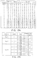
- Figure 5 is a table showing various information of the uplink DPCCH, wherein channel bit and symbol rates are those just prior to spreading. (At the time of this technical specification, the exact number of bits of the different uplink DPCCH fields of Figure 4 (N pilot , N TPC , N FBI , and N TFCI ) was not determined.)
- Figure 6 is a table illustrating pilot bit patterns of the uplink DPCCH, and more particularly, 6-bit and 8-bit pilot bit patterns for each slot.
- the non-shaded sequence is used for channel estimation, and shaded sequence can be used as frame synchronization words or sequences.
- the pilot bits other than frame synchronization word, e.g., channel estimation word, have a value of 1.
- the sequences at bit #1, at bit #3, at bit #5, and at bit #7 are used as the frame synchronization words.
- the pilot bits of each sequences slot are either 6 or 8 in number, a total of four is used as the frame synchronization word.
- the number of pilot bits used as the frame synchronization word is 64 bits per frame.
- Figure 7 shows a spreading/scrambling arrangement for the uplink DPCH based on the 3GPP RAN standard.
- the arrangement of Figure 7 is provided for the execution of a quadrature phase shift keying (QPSK) operation where the uplink DPDCH and DPCCH are mapped into I and Q channel branches, respectively.
- QPSK quadrature phase shift keying
- the spreading is an operation for switching all symbols through the respective channel branches to a plurality of chips.
- the I and Q channel branches are spread respectively at chip rates based on two different orthogonal variable spreading factors (OVSFs), or channelizing codes C D and C C .
- OVSF represents the number of chips per symbol on each channel branch.
- the spread of two channel branches are summed and then complex-scrambled by a specific complex scrambling code C scramb .
- the complex-scrambled result is separated into real and imaginary and then transmitted after being placed on respective carriers.
- Figure 8 illustrates a frame structure of a downlink DPCH based on the 3GPP RAN standard.
- the number of pilot bits (or symbols) in the uplink DPCH is 6 or 8 because the uplink DPCH is activated at a fixed rate of 16Kbps.
- the downlink DPCH is activated at a variable rate, it has pilot symbol patterns illustrated in Figure 9.
- the downlink DPCH is provided with two types of channels, e.g., a dedicated physical data channel (DPDCH) and a dedicated physical control channel (DPCCH).
- DPDCH dedicated physical data channel
- DPCCH dedicated physical control channel
- the downlink DPDCH is adapted to transport the dedicated data
- the downlink DPCCH is adapted to transport the control information.
- the downlink DPCCH for transporting the control information is composed of various fields such as a pilot field 27, TPC field 26 and TFCI field 25.
- the pilot field 27 includes pilot symbols for supporting the channel estimation for coherent detection.
- Figure 9 is a table illustrating pilot symbol patterns contained in the downlink DPCCH, which are classified according to different symbol rates of the downlink DPCCH. For example, in the case where the symbol rate is 16, 32, 64 or 128Kbps, each slot includes four pilot symbols for an I channel branch and four pilot symbols for a Q channel branch, totaling eight pilot symbols.
- the non-shaded sequence is used for channel estimation and shaded sequences can be used as frame synchronization words.
- the remaining pilot symbols other than the frame synchronization word (e.g., channel estimation) have a value of 11.
- the symbol rate is 16, 32, 64 or 128Kbps
- the sequences, formed by pilot symbols from slot #1 to slot #16, at symbol #1 and at symbol #3 are used as the frame synchronization words. Accordingly, because the number of pilot symbols used as the frame synchronization words is 4 per slot, 64 pilot symbols are used in each radio frame.
- Figure 10 illustrates a spreading/scrambling arrangement for the downlink DPCH based on the 3GPP RAN standard.
- the arrangement of Figure 10 is provided for the spreading and scrambling of the downlink DPCH and a common control physical channel (CCPCH).
- CPCH common control physical channel
- a QPSK operation is performed with respect to a pair of symbols of the two channels in such a manner that they are serial-to-parallel converted and then mapped into I and Q channel branches, respectively.
- the I and Q channel branches are spread respectively at chip rates based on two equal channelizing codes C ch .
- the spread of the two channel branches are summed and then complex-scrambled by a specific complex scrambling code C scramb .
- the complex-scrambled result is separated into real and imaginary and then transmitted, after being placed on respective carriers. Noticeably, the same scrambling code is used for all physical channels in one cell, whereas different channelizing codes are used for different physical channels.
- Data and various control information are transported to a receiver through the uplink and downlink DPCHs subjected to the above-mentioned spreading and scrambling.
- the TS S1.11 v1.1.0 specification also specified a primary common control physical channel (PCCPCH), which is a fixed rate downlink physical channel used to carry the broadcast channel (BCH), and a secondary common control physical channel (SCCPCH) used to carry the forward access channel (FACH) and the paging channel (PCH) at a constant rate.
- PCCPCH primary common control physical channel
- SCCPCH secondary common control physical channel
- FACH forward access channel
- PCH paging channel
- Figures 11A and 11B illustrate the frame structure of PCCPCH and SCCPCH, each having a pilot field.
- the TS S1.11 v1.1.0 specification recommended the pilot patterns for the PCCPCH and SCCPCH.
- the TS S1.11 v1.1.0 specification recommended the pilot pattern of the DPCH channel for the diversity antenna using open loop antenna diversity based on space time block coding based transmit diversity (STTD) and diversity antenna pilot patterns for PCCPCH and SCCPCH. Those patterns can be found in the TS S1.11 v1.1.0 specification, and detailed description is being omitted.
- STTD space time block coding based transmit diversity
- an autocorrelation function For frame synchronization, an autocorrelation function must be performed on the basis of the pilot pattern sequence. In the pilot sequence design, finding an autocorrelation of a sequence with the lowest out-of-phase coefficient is important to decrease the probability of false alarm regarding the synchronization. A false alarm is determined when a peak is detected when there should not be a peak detection.
- the result of the autocorrelation for a frame with a sequence at a prescribed pilot bit should have same maximum values at zero and middle time shifts of one correlation period, which are different in polarity, and the remaining sidelobes at time shifts other than zero and middle should have a value of zero.
- the various pilot patterns recommended in the TS S1.11 v1.1.0 do not meet this requirement, both in the uplink and downlink.
- the pilot patterns used as frame synchronization words or sequences do not achieve the optimal results. Further, the background pilot patterns do not rapidly and accurately perform the frame synchronization. Moreover, the above pilot patterns and frame synchronization sequences do not provide optimal cross-correlation and autocorrelation. Additionally, neither the TS specification nor the article provides a solution of the use of the pilot patterns for slot-by-slot double check frame synchronization scheme, and neither discloses the use of the frame synchronization sequence for channel estimation.
- An object of the present invention is to obviate at least the problems and disadvantages of the related art.
- An object of the present invention is to provide frame synchronization words resulting in optimal autocorrelation results.
- a further object of the present invention is to eliminate or prevent sidelobes.
- a further object of the present invention is to provide maximum values at zero and middle time shifts.
- Another object of the present invention is to provide a synchronization word for at least one of rapid and accurate frame synchronization.
- Another object of the present invention is to provide a slot-by-slot double check frame synchronization scheme.
- Still another object of the present invention is to provide a frame synchronization word which can be used for channel estimation.
- Still another object of the present invention is to provide good cross-correlation and autocorrelation simultaneously.
- the present invention can be achieved in a whole or in parts by a method for synchronizing a frame using an optimal pilot symbol, comprising the steps of: (1) receiving a pilot symbol of each slot in the frame through respective physical channels on a communication link; (2) correlating a received position of each of the pilot symbols to a corresponding pilot sequence; (3) combining and summing more than one results of the correlations, and deriving a final result from the correlations in which sidelobes from the results of the correlations are offset; and (4) synchronizing the frame using the final result.
- the pilot symbols are combined into each of the pilot sequences such that the final result of the correlations shows sidelobes with 0" values excluding particular positions of correlation periods.
- the pilot symbol is a combination of pilot symbols in a form of (a,/a).
- the pilot sequence provides least correlation resultants at positions excluding the starting points and half of the starting points in the correlation periods.
- the pilot symbols excluding the pilot symbols used in the correlation is used in a channel estimation for detecting coherent.
- the pilot symbol of each slot in the frame is transmitted, with the pilot symbol contained in a pilot field of an exclusive physical control channel among respective exclusive channels on the communication link.
- the pilot sequences different from each other on an up communication link are used in the correlation according to values of bits included in a pilot field of an exclusive physical control channel.
- the pilot sequences different from each other on a down communication link are used in the correlation according to a symbol rate of an exclusive physical control channel.
- the present invention can be also achieved in a whole or in parts by a method for synchronizing a frame using an optimal pilot symbol, comprising the steps of: (1) receiving a pilot symbol of each slot in the frame through respective physical channels on a communication link; (2) correlating a received position of each of the pilot symbols to a corresponding pilot sequence; (3) combining and summing more than one results of the correlations, and deriving a final result from the correlations in which sidelobes from the results of the correlations have minimum values and the results of the correlations at starting points and middle points of correlation periods have maximum values with different polarity; and (4) synchronizing the frame using the final result.
- the present invention can be achieved in a whole or in parts by a method of eliminating sidelobes in a communication channel between a base station and a mobile station, comprising the steps of: generating control signals and data signals within the communication channel, the control signals having a first sequence of L-bits and a second sequence of L-bits; generating a first set of prescribed values based on the first sequence, which has a first prescribed relationship with the first set of prescribed values; generating a second set of prescribed values based on the second sequence, which has a second prescribed relationship with the second set of prescribed values; and combining the first and second sets of prescribed values.
- the present invention can be achieved in a whole or in parts by a method of establishing a communication channel, the method comprising the steps of: generating a plurality of frames; generating a L-number of slots for each frame, each slot having a pilot signal of N-bits and a corresponding bit in each slot forming a word of L-sequence of pilot bits such that there is N number of words, wherein the number of bit values of two pilot bits which are the same between two adjacent words from 1 to L slots minus the number of bit values of two pilot bits which are different between the two adjacent words from 1 to L is zero or a prescribed number close to zero.
- the present invention can be achieved in a whole or in parts by a method of establishing a communication channel having at least one of frame synchronization and channel estimation, the method comprising the steps of: generating a plurality of frames; generating a L-number of slots for each frame, each slot having a pilot signal of N-bits and a corresponding bit in each slot forming a word of L-sequence of pilot bits such that there is N number of words, wherein the words have at least one of the following characteristics: cross-correlation between two adjacent sequences used for frame synchronization is zero at zero time shift, or cross-correlation between a word used for frame synchronization and a word used for channel estimation is zero at all time shifts.
- the present invention can be achieved in a whole or in parts by a method of reducing sidelobes for frame synchronization, comprising the steps of: generating a plurality of frame synchronization words, each frame synchronization word having a plurality of bits; performing autocorrelation functions on a pair of frame synchronization words to generate a pair of prescribed value sets; and combining the pair of prescribed value sets such that two peak values equal in magnitude and opposite in polarity are achieved at zero and middle time shifts.
- the present invention can be achieved in a whole or in parts by a method of generating pilot signals of a prescribed pattern within a frame having L-number of slots, comprising the steps of: generating N-number of pilot bits for each slot; and forming N-number of words of L-bit based on above step, wherein a prescribed number of words is used for frame synchronization words and each frame synchronization word has a first prescribed number bo of bit values of "0" and a second prescribed number b 1 of bit values of "1", such that b 1 -b 0 is equal to zero or a number close to zero.
- the present invention can be achieved in a whole or in parts by a communication link between a user equipment and a base station comprising a plurality of layers, wherein one of the layers is a physical layer for establishing communication between the user equipment and the base station and the physical layer has at least one of data and control information, one of the control information being a pilot field of N-bits transmitted for L-number of slots such that N-number of words of L-bit are formed, wherein cross-correlation between two adjacent words used for frame synchronization is zero at zero time shift or cross-correlation between a word used for frame synchronization and a word used for channel estimation is zero at all time shifts.
- the present invention can be achieved in a whole or in parts by a correlator circuit for at least one of a user equipment and a base station, comprising: a plurality of latch circuits, each latch circuit latching a word formed by a pilot bit from a plurality of slots; a plurality of correlators, each correlator coupled to a corresponding latch circuit and correlating the word to a set of prescribed values; and a combiner that combines the set from each correlator such that maximum peak values of equal in magnitude and opposite in polarity are formed at zero and middle time shifts.
- the present invention can be achieved in a whole or in parts by a communication device comprising: means for transmitting at least one of data and control information; means for receiving at least one of data and control information, wherein the receiving means includes: a plurality of latch circuits, each latch circuit latching a word formed by a pilot bit from a plurality of slots; a plurality of correlators, each correlator coupled to a corresponding latch circuit and correlating the word to a set of prescribed values; a plurality of buffers, each buffer coupled to a corresponding correlator to store the set of prescribed values; and a combiner that combines the set from each buffer such that maximum peaks of equal in magnitude and opposite in polarity are formed at zero and middle time shifts.
- the new frame synchronization words in accordance with the preferred embodiment have the lowest out-of-phase values of autocorrelation function with two peak values equal in magnitude and opposite in polarity at zero and middle shifts.
- the frame synchronization words are suitable for frame synchronization confirmation since by simply adding
- the UE establishes downlink chip synchronization and frame synchronization based on the Primary CCPCH synchronization timing and the frame offset group, slot offset group notified from the network.
- the frame synchronization can be confirmed using the frame synchronization word.
- the network establishes uplink channel chip synchronization and frame synchronization based on the frame offset group and slot offset group.
- the frame synchronization can also be confirmed using the frame synchronization word.
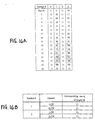
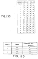
- Figure 12A is a table illustrating the frame synchronization words C 1 to C i-th in accordance with a preferred embodiment of the present invention, where each word comprises L number (L>1) of sequence of pilot bits from a prescribed bit position of the N pilot bits (N pilot >0) from each slot of L number of slots.
- the number of synchronization words i equals 8
- the number of slots L 16
- the number of pilot bits N pilot in each slot is between 4 and 16, but the present invention is applicable to different variations of i, L, and N pilot .
- the synchronization words C 1 -C 8 of the preferred embodiment can be divided into 4 classes (E-H, referred to as Preferred Correlation Sequence Pair (PCSP)) according to the autocorrelation function of the synchronization words, as follows:
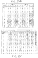
- Figure 12B is a table illustrating the autocorrelation function of 1 to 16 sequences of pilot bits of each frame synchronization word classified in classes E, F, G and H within one correlation period from a time shift of 0 to 15.
- each class contains 2 sequences, and sequences of the same class have the same autocorrelation function.
- the synchronization words have the lowest out-of-phase values of autocorrelation function with two peak values equal in magnitude and opposite in polarity at zero and middle shifts.
- the results R 1 and R 2 of the autocorrelation function are complements of each other.
- the shaded pattern of Figures 14A and 14B are used for frame synchronization (which can also be used for channel estimation), and the pilot bit other than the frame synchronization words (e.g., channel estimation) has a value of 1.
- Figure 14C is a table illustrating the mapping relationship between the 8 synchronization words C 1 -C 8 of Figure 12A and shaded pilot bit patterns of Figures 14A and 14B, where frame synchronization words C 1 , C 2 , C 3 , and C 4 are the elements of the set ⁇ E, F, G, and H ⁇ , respectively.
- N pilot 8
- the frame synchronization words at bit #1 (C 1 ), at bit #3 (C 2 ), at bit #5 (C 3 ) and at bit #7 (C 4 ) are used in the autocorrelation process for the frame synchronization.
- N pilot 5, 6, 7, and 8 in each slot, a total of four frame synchronization words are used.
- the number of pilot bits used for the frame synchronization is only 64 per frame in the preferred embodiment.
- the number of words used for frame synchronization can vary depending on variations of N pilot .
- N pilot 1
- one of the frame synchronization words C 1 -C 8 can be used for both frame synchronization and channel estimation due to the novel feature of the preferred embodiment.
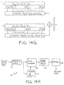
- Figure 14D illustrates a correlation circuit for frame synchronization based on pilot bits of the uplink DPCCH in accordance with a preferred embodiment of the present invention when frame synchronization words C 1 -C 4 are used.
- the frame synchronization words C 1 -C 4 are latched in latch circuits 31-34, respectively.
- Figure 14E is a table illustrating the correlation results at points A 1 -A 4 , and the summing of the correlation results at point B. As shown, the result has maximum values of opposite polarity at zero and middle time shifts R(0) and R(8). Further, the remaining sidelobes at time shifts other than zero and middle have values of zero after the addition at point B. The sidelobes are eliminated or minimized, and the results at point B correspond to the optimal results of Figure 13B.
- Figure 14F is a table illustrating various results of the addition of correlation results of points A 1 -A 4 based on the uplink pilot patterns of the frame synchronization words C 1 -C 4 in accordance with the preferred embodiment of the present invention.
- the respective addition of the autocorrelation results of points (A 1 +A 2 ), (A 3 +A 4 ), (A 1 +A 4 ) and (A 2 +A 3 ) exhibit the same characteristics of the optimal results illustrated in Figure 13A.
- Figure 14G illustrates a correlator circuit for frame synchronization based on pilot bit sequences of an uplink DPCCH in accordance with an alternative embodiment.
- the elements are the same as the correlator circuit of Figure 14D.
- the frame synchronization words of (C 1 and C 2 ), (C 2 and C 3 ), (C 3 and C 4 ), or (C 4 and C 1 ) are correlated and summed to provide the results at point D.
- Figure 14H illustrates the receiver circuit 60 of a base station or a user equipment to recover the received spread signal including the frame synchronization words in the pilot field.
- the channel estimator and frame synchronizer 62 After despreading the received spread signal by the despreading circuit 61, the channel estimator and frame synchronizer 62 performs the channel estimation and the frame synchronization based on the pilot field.
- the Rake combiner 63 uses the results of the channel estimator and frame synchronizer, and after rake combining, the data is deinterleaved by the deinterleaving circuit 64 in the reverse order of the transmitter side. Thereafter, the data is recovered after decoding by a decoder 65.
- cross-correlation and autocorrelation simultaneous is difficult to achieve, where cross-correlation relates to different words at different time shifts and autocorrelation relates to same sequences which are time shifted version.
- the good cross-correlation and autocorrelation of the present invention is based on unique properties of the frame synchronization words.
- each word has substantially the same number of 1 and 0.
- the number (b 1 ) of pilot bits of a frame synchronization words having a value of 1 minus the number (bo) of pilot bits of the frame synchronization having a value of 0 is equal to zero or close to zero.
- the result of b 1 -b 0 is plus or minus one, e.g., close to zero.
- N pilot 5
- cross-correlation between two adjacent words used for frame synchronization is zero (orthogonal) at zero time shift.
- the cross-correlation between a word used for frame synchronization and the sequence used for channel estimation is zero (orthogonal) at all time shifts.
- there are an even number of words used for frame synchronization but all words perform channel estimation, wherein between adjacent words used for frame synchronization, there is substantially zero cross-correlation.
- the words used for frame synchronization has substantially zero cross-correlation with words not used for frame synchronization, i.e., channel estimation, at any time shifts.
- each N pilot words corresponds to a prescribed number by an autocorrelation function such that when a pair from a set of autocorrelated results corresponding to words used for frame synchronization is combined, two peak values equal in magnitude and opposite in polarity are achieved at zero and middle time shift while sidelobes are substantially eliminated at time shifts other than zero and middle.
- Autocorrelation in accordance with the present invention can be generally defined as a correlation between a word and its time shifted replica (including replica at zero time shift), where correlation is the number of bit values which are the same between two words minus the number of bit values which are different between the same two words.
- R 1 and R 2 are complements of each other.
- the shaded symbols of Figure 15A can be used for frame synchronization, and the value of pilot symbol other than for frame synchronization word, e.g., channel estimation (channel estimation word), is 11.
- Figure 15B illustrates the mapping relationship between the 8 frame synchronization words of Figure 12A, and shaded pilot symbol pattern of Figure 15A.
- the symbol #1 includes two frame synchronization words of C 1 (for the I channel branch I-CH, i.e., left sequence of bits from slot #1 to slot #16) and C 2 (for the Q channel branch Q-CH, i.e., right sequence of bits from slot #1 to slot #16).
- the characteristics described for uplink DPCCH is applicable to downlink DPCH.
- the number (b 3 ) of bit values which are the same (0,0 and 1,1) between adjacent words i.e., between synchronization word of I channel branch and synchronization word of Q channel branch of a frame synchronization symbol, or between a channel estimation word of the Q channel branch and a frame synchronization word of the I channel branch, which are adjacent, or between a frame synchronization word of the Q channel branch and a channel estimation word of the I channel branch, which are adjacent
- the number (b 4 ) of bit values which are different (1,0 and 0,1) between adjacent words i.e., between synchronization word of I channel branch and synchronization word of Q channel branch of a frame synchronization symbol, or between a channel estimation word of the Q channel branch and a frame synchronization word of the I channel branch, which are adjacent, or between
- the number of a pair of adjacent bits i.e., one bit from the Q channel branch of the symbol #0 and one bit from the I channel branch of the symbol #1, having bit values of 1,1 and 0,0 is the same as the number of adjacent bits having bit values of 1,0 and 0,1.
- b 3 -b 4 0.
- the result of b 3 -b 4 is plus or minus one, e.g., a prescribed number close to zero.
- the operation and components are the same as the correlation circuit of Figure 14D for uplink DPCCH, except for the reception of I channel branch and Q channel branch synchronization words.
- the results of points A 1 -A 4 and point B is the same as Figure 14E.
- the sidelobes are eliminated or minimized, and the results correspond to the optimal results of Figure 13B. Because the number of pilot symbols (or pilot bits) used for the frame synchronization is 2 symbols per slot (or 4 bit per slot), 32 pilot symbols (or 64 pilot bits) are used in each radio frame for the frame synchronization.
- the correlator circuit of Figure 14G can be used.
- the I and Q channel frame synchronization words are inputted to the correlator circuit.
- the summation result would be the same as Figure 14F, which corresponds to the optimal results of Figure 13A.
- the number of pilot symbols (or pilot bits) used for the frame synchronization is 1 symbol per slot (or 2 bits per slot), and 16 symbols (or 32 pilot bits) are used in each radio frame for the frame synchronization.
- the correlation circuit of Figure 15C can be expanded to accommodate the additional frame synchronization words of the I and Q channel branches of pilot symbol #5 and symbol #7.
- the summation result would be similar to the optimal results of Figure 13B, but the maximum peak values of opposite polarity would be 128 (8*L) and -128 (-8*L).
- the number of pilot symbols (or pilot bits) used for the frame synchronization is 4 symbols per slot (or 8 bits per slot), and 64 pilot symbols (or 128 pilot bits) are used in each radio frame for the frame synchronization.
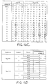
- Figure 16A illustrates pilot symbol pattern of PCCPCH.
- the shaded symbols can be used for frame synchronization, and the value of pilot symbol other than for frame synchronization is 11.
- Figure 16B illustrates the mapping relationship between the synchronization words C 1 -C 8 of Figure 12A, and the shaded pilot symbol patterns of Figure 16A.
- Figure 16C illustrates pilot symbol pattern of SCCPCH.
- the shaded symbols can be used for frame synchronization, and the value of pilot symbol other than for frame synchronization is 11.
- Figure 16D illustrates the mapping relationship between the synchronization words C 1 -C 8 of Figure 12A, and the shaded pilot symbol patterns of Figure 16C.
- the frame synchronization words of PCCPCH and SCCPCH is based on the frame synchronization words C 1 -C 8 , and the disclosure for the uplink DPCCH and the downlink DPCH is applicable.
- the various characteristics including cross-correlation and autocorrelation, operations and implements are omitted since one of ordinary skill in the art can readily appreciate the present invention based on the uplink DPCCH and downlink DPCH.
- the non-shaded symbols are the pilot symbols not used for frame synchronization comprises symbols of 11, and the shaded symbols are used for frame synchronization.
- the frame synchronization words of the pilot pattern are used for frame synchronization confirmation, and the summation of autocorrelated values for each frame synchronization words is required.
- the property of summation of autocorrelated values of frame synchronization words is very important.
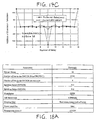
- Correlation to a prescribed frame synchronization word is optimum method for frame synchronization. Since the frame synchronization word of pilot pattern is used for frame synchronization confirmation, the following events and parameters are used to evaluate the performance of frame synchronization confirmation using the frame synchronization words of the preferred embodiment and the current pilot patterns:
- the probability of a frame synchronization confirmation is greatly affected by the probability of a false alarm since P S is proportional to P D and (1-P FA ) 14 or (1-P FA ) 15 .
- P S is proportional to P D and (1-P FA ) 14 or (1-P FA ) 15 .
- P FA 10 -1
- the performance of frame synchronization can be sufficiently evaluated by selecting the threshold so that the P FA is much smaller than (1-P D ).
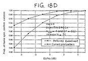
- Figure 18A The parameters of Figure 18A are used for obtaining P D , P FA , and P S on uplink DPCCH and downlink DPCH over additive white Gaussian noise (AWGN).
- the P D and P S of the pilot patterns of the preferred embodiment are greater than that of current pilot pattern. Furthermore, the P FA of the pilot patterns in accordance with the preferred embodiment are also smaller than that of the current pilot patterns.
- the frame synchronization words of the preferred embodiment are especially suitable for frame synchronization confirmation.
- double maximum values equal in magnitude and opposite polarity at zero and middle shifts are obtained. This property can be used to slot-by-slot and double-check frame synchronization timing and reduce the synchronization search time.
- the performance of frame synchronization confirmation over AWGN using pilot pattern illustrate the significant differences between the frame synchronization performance of the pilot pattern of the preferred embodiment and the current pilot pattern.
- Figure 19A illustrates new pilot symbol patterns of Downlink DPCH for the diversity antenna using a space time block coding based transmit diversity (STTD).
- STTD space time block coding based transmit diversity
- Figure 19B illustrates the mapping relationship between the 8 words C 1 -C 8 of Figure 12A and shaded pilot symbol patterns of Figure 19A.
- Figure 19C illustrates the new diversity antenna pilot symbol pattern for PCCPCH.
- the pilot symbols of Figure 19C are encoded to be orthogonal to the pilot symbols of Figure 16A.
- Figure 19D illustrates the mapping relationship between the words C 1 -C 8 of Figure 12A and shadowed pilot symbol patterns of Figure 19C.
- Figure 19E illustrates the new pilot symbol pattern for the diversity antenna when STTD encoding is used on the SCCPCH.
- Figure 19F illustrates the mapping relationship between the words C 1 -C 8 of Figure 12A and shaded pilot symbol patterns of Figure 19E.
- the frame synchronization words C 1 -C 16 can be classified into the PCSP of the first embodiment, as follows:
- FIG. 20B is a table illustrating the autocorrelation function of the pilot bits of each frame synchronization word classified in the PCSP.
- each class contains four sequences and the sequences of the same class have the same autocorrelation function.
- Figures 20E and 20F illustrate the pilot symbol pattern of downlink DPCH with 8, 16, 32, 64, 128, 256, 512, 1024, 2048 and 4096 ksps
- Figure 20G illustrates a mapping relationship between the alternative frame synchronization words C 1 -C 16 of Figure 20A and the shaded frame synchronization words of Figures 20E and 20F.
- Figure 20H illustrates the pilot symbol pattern of downlink PCCPCH
- Figure 20I illustrates a mapping relationship between the alternative frame synchronization words C 1 -C 16 of Figure 20A and the shaded frame synchronization words of Figure 20H.
- the frame synchronization words of the preferred embodiment are especially suitable for frame synchronization confirmation.
- double maximum values equal in magnitude and opposite polarity at zero and middle shifts are obtained. This property can be used to slot-by-slot and double-check frame synchronization timing and reduce the synchronization search time.
- the present invention allows a simpler construction of the correlator circuit for a receiver, thereby reducing the complexity of the receiver. Due to various advantages of the present invention, the first preferred embodiment has been accepted by the 3GPP, as shown in TS 25.211 v2.0.1, distributed June 1999, whose entire disclosure is hereby incorporated by reference therein.
- the frame synchronization words are used to design the regular pilot patterns and diversity antenna pilot patterns of uplink DPCH, and downlink DPCH and SCCPCH of the preferred embodiment.
- the words C 1 -C 8 of Figure 21 are suitable for frame synchronization confirmation.
- the two words within the same class are PCSP.
- the shaded parts of Figures 23A, 23C, 23E and 23F can be used for frame synchronization words, and the value of pilot bit other than the frame synchronization word is 1.
- Figures 23B and 23D illustrate the mapping relationship between the frame synchronization words of Figure 21, and shaded frame synchronization words of Figures 23A and 23D, respectively.
- Figure 23G illustrates the mapping relationship between the frame synchronization words of Figure 21, and the shaded frame synchronization words of Figures 23E and 23F.
- each word has substantially the same number of 1 and 0.
- the result of b 1 -b 0 is plus or minus one, e.g., close to zero.
- the result of b3-b4 equals plus or minus one, e.g., close to zero.
- the Random Access Channel is an uplink transport channel that is used to carry control information from the UE.
- the RACH may also carry short user packets.
- the RACH is always received from the entire cell.
- Figure 23H illustrates the structure of random access channel.
- the control part has 8 known pilot bits to support channel estimation for coherent detection and 2 bits of rate information. This corresponds to a spreading factor of 256 for the message control part.
- Figure 23I illustrates the random access message control fields and there is always 8 pilot symbols per slot for channel estimation. Due to the unique characteristics of the frame synchronization words in accordance with the preferred embodiment, the frame synchronization words C 1 -C 8 can be used in the pilot bit pattern of the RACH for channel estimation.
- the shaded parts of Figure 24A can be used for frame synchronization symbols, each symbol having one frame synchronization word for the I channel branch and another frame synchronization word for the Q channel branch, and the value of pilot symbol other than the frame synchronization word is 11.
- Figure 24B illustrates the mapping relationship between the frame synchronization words C 1 -C 8 of Figure 21 and shaded pilot symbol patterns of Figure 24A.
- Figure 24C illustrates the pilot symbol patterns of downlink DPCH for the diversity antenna using STTD.
- Figure 24D illustrates the mapping relationship between the frame synchronization words C 1 -C 8 of Figure 21 and shaded pilot symbol patterns of Figure 24C.
- Figure 25B illustrates the mapping relationship of the frame synchronization words C 1 -C 8 of Figure 21 and shaded pilot symbol patterns of Figure 25A
- Figure 25D illustrates the mapping relationship between the frame synchronization words C 1 -C 8 of Figure 21 and shaded pilot symbol patterns of Figure 25C.
- the frame synchronization is confirmed if the output of the correlator using the frame synchronization word exceeds the predetermined threshold.
- the success of the frame synchronization confirmation is determined when the successive S R frame synchronization is confirmed. Otherwise, the frame synchronization confirmation failure is determined.
- the probability of a frame synchronization confirmation success is defined by
- the probability of a false alarm can be expressed as
- Figure 26A The parameters of Figure 26A are used to evaluate the performance of the pilot bit pattern on uplink DPCCH over AWGN.
- double-check frame synchronization scheme can be obtained. There is significant gain about 4dB by employing the double-check frame synchronization confirmation method compared to single-check method.
- the complexity of the correlator circuit is doubled since an auto-correlator for positive peak detection and a cross-correlator for negative peak detection are used.
- the single-check frame synchronization confirmation method can also be employed; whereas, in the case of 16 slots, there is some problems due to +4 or -4 out-of-phase coefficients.
Landscapes
- Engineering & Computer Science (AREA)
- Signal Processing (AREA)
- Computer Networks & Wireless Communication (AREA)
- Power Engineering (AREA)
- Mobile Radio Communication Systems (AREA)
- Synchronisation In Digital Transmission Systems (AREA)
- Time-Division Multiplex Systems (AREA)
- Cable Transmission Systems, Equalization Of Radio And Reduction Of Echo (AREA)
Priority Applications (3)
| Application Number | Priority Date | Filing Date | Title |
|---|---|---|---|
| EP20090154135 EP2099143B1 (de) | 1999-03-15 | 2000-03-15 | Sender mit Pilotsignalsynchronisierung |
| EP20090154137 EP2081306B1 (de) | 1999-03-15 | 2000-03-15 | Sender mit Pilotsignalsynchronisierung |
| EP20070015144 EP1850511B1 (de) | 1999-03-15 | 2000-03-15 | Pilotsignale zur Synchronisation und/oder Kanalschätzung |
Applications Claiming Priority (26)
| Application Number | Priority Date | Filing Date | Title |
|---|---|---|---|
| KR8603099 | 1999-03-15 | ||
| KR1019990008630A KR100294711B1 (ko) | 1999-03-15 | 1999-03-15 | 최적의 파일럿 심볼을 이용한 프레임 동기 방법 |
| KR1285799 | 1999-04-12 | ||
| KR1019990012856A KR100323767B1 (ko) | 1999-04-12 | 1999-04-12 | 프레임 동기 유지 방법 |
| KR1019990012857A KR100320421B1 (ko) | 1999-04-12 | 1999-04-12 | 최적의 파일럿 심볼을 이용한 프레임 동기 확인 방법 |
| KR1285699 | 1999-04-12 | ||
| KR1019990015722A KR100317256B1 (ko) | 1999-04-30 | 1999-04-30 | 최적의 파일럿 심볼을 이용한 프레임 동기 방법 |
| KR1572299 | 1999-04-30 | ||
| KR1950599 | 1999-05-28 | ||
| KR1950699 | 1999-05-28 | ||
| KR1019990019506A KR20000075107A (ko) | 1999-05-28 | 1999-05-28 | 최적의 프레임 동기화 부호를 이용한 셀 탐색 방법 |
| KR1019990019505A KR100331870B1 (ko) | 1999-05-28 | 1999-05-28 | 파일럿 패턴 할당 및 배치 방법 |
| KR1961099 | 1999-05-29 | ||
| KR1019990019610A KR100304938B1 (ko) | 1999-05-29 | 1999-05-29 | 최적의 파일럿 패턴을 이용한 프레임 동기 방법 |
| KR1019990023141A KR100331871B1 (ko) | 1999-06-19 | 1999-06-19 | 슬롯별 상관 결과를 이용한 프레임 동기 확인 방법 |
| KR1019990023140A KR100308151B1 (ko) | 1999-06-19 | 1999-06-19 | 샘플링된 상관 결과를 이용한 프레임 동기 확인 방법 |
| KR2314199 | 1999-06-19 | ||
| KR2314099 | 1999-06-19 | ||
| KR1019990023568A KR100331872B1 (ko) | 1999-06-22 | 1999-06-22 | 프레임 동기를 위한 파일럿 시퀀스 생성 방법 |
| KR2356899 | 1999-06-22 | ||
| KR1019990023937A KR100606673B1 (ko) | 1999-06-24 | 1999-06-24 | 파일럿 패턴을 이용한 프레임 동기 방법 |
| KR2393799 | 1999-06-24 | ||
| KR1019990026689A KR100331874B1 (ko) | 1999-07-02 | 1999-07-02 | 공통 파일럿 채널의 파일럿 패턴을 이용한 프레임 동기 방법 |
| KR2668999 | 1999-07-02 | ||
| KR1019990034212A KR100339337B1 (ko) | 1999-08-18 | 1999-08-18 | 최적의 파일럿 패턴을 이용한 프레임 동기 장치 및 방법 |
| KR3421299 | 1999-08-18 |
Related Child Applications (5)
| Application Number | Title | Priority Date | Filing Date |
|---|---|---|---|
| EP20090154135 Division EP2099143B1 (de) | 1999-03-15 | 2000-03-15 | Sender mit Pilotsignalsynchronisierung |
| EP20070015144 Division EP1850511B1 (de) | 1999-03-15 | 2000-03-15 | Pilotsignale zur Synchronisation und/oder Kanalschätzung |
| EP07015144.4 Division-Into | 2007-08-02 | ||
| EP09154135.9 Division-Into | 2009-03-02 | ||
| EP09154137.5 Division-Into | 2009-03-02 |
Publications (3)
| Publication Number | Publication Date |
|---|---|
| EP1037407A2 true EP1037407A2 (de) | 2000-09-20 |
| EP1037407A3 EP1037407A3 (de) | 2003-10-15 |
| EP1037407B1 EP1037407B1 (de) | 2010-07-07 |
Family
ID=27584380
Family Applications (5)
| Application Number | Title | Priority Date | Filing Date |
|---|---|---|---|
| EP20090154135 Expired - Lifetime EP2099143B1 (de) | 1999-03-15 | 2000-03-15 | Sender mit Pilotsignalsynchronisierung |
| EP20000302093 Expired - Lifetime EP1039654B1 (de) | 1999-03-15 | 2000-03-15 | Pilotsignale zur Synchronisierung und/oder Kanalschätzung |
| EP20000302094 Expired - Lifetime EP1037407B1 (de) | 1999-03-15 | 2000-03-15 | Pilotsignale zur Synchronisierung und/oder Kanalschätzung |
| EP20090154137 Expired - Lifetime EP2081306B1 (de) | 1999-03-15 | 2000-03-15 | Sender mit Pilotsignalsynchronisierung |
| EP20070015144 Expired - Lifetime EP1850511B1 (de) | 1999-03-15 | 2000-03-15 | Pilotsignale zur Synchronisation und/oder Kanalschätzung |
Family Applications Before (2)
| Application Number | Title | Priority Date | Filing Date |
|---|---|---|---|
| EP20090154135 Expired - Lifetime EP2099143B1 (de) | 1999-03-15 | 2000-03-15 | Sender mit Pilotsignalsynchronisierung |
| EP20000302093 Expired - Lifetime EP1039654B1 (de) | 1999-03-15 | 2000-03-15 | Pilotsignale zur Synchronisierung und/oder Kanalschätzung |
Family Applications After (2)
| Application Number | Title | Priority Date | Filing Date |
|---|---|---|---|
| EP20090154137 Expired - Lifetime EP2081306B1 (de) | 1999-03-15 | 2000-03-15 | Sender mit Pilotsignalsynchronisierung |
| EP20070015144 Expired - Lifetime EP1850511B1 (de) | 1999-03-15 | 2000-03-15 | Pilotsignale zur Synchronisation und/oder Kanalschätzung |
Country Status (11)
| Country | Link |
|---|---|
| US (1) | US7616681B2 (de) |
| EP (5) | EP2099143B1 (de) |
| JP (1) | JP4318963B2 (de) |
| KR (1) | KR100294711B1 (de) |
| CN (3) | CN1124708C (de) |
| AT (2) | ATE473562T1 (de) |
| BR (1) | BRPI0001674B1 (de) |
| DE (2) | DE10012286B4 (de) |
| ES (3) | ES2502015T3 (de) |
| GB (1) | GB2350760B (de) |
| HK (1) | HK1077134A1 (de) |
Cited By (4)
| Publication number | Priority date | Publication date | Assignee | Title |
|---|---|---|---|---|
| WO2003081822A1 (en) * | 2002-03-22 | 2003-10-02 | Linkair Communications,Inc. | A coding method to create mismatched spread spectrum sequence with zero correlation window |
| WO2006119583A1 (en) * | 2005-05-13 | 2006-11-16 | Dspace Pty Ltd | Method and system for communicating information in a digital signal |
| AU2006246322B2 (en) * | 2005-05-13 | 2010-04-22 | Dspace Pty Ltd | Method and system for communicating information in a digital signal |
| EP1508816B1 (de) * | 2003-08-22 | 2016-11-16 | Sound View Innovations, LLC | Verfahren zur Bestätigung der Erfassung einer Korrelationsspitze mittels eines Empfängers für ein satellitengestützes Navigationssystem |
Families Citing this family (23)
| Publication number | Priority date | Publication date | Assignee | Title |
|---|---|---|---|---|
| KR100685960B1 (ko) * | 2000-02-03 | 2007-02-23 | 엘지전자 주식회사 | 파일럿 패턴을 이용한 프레임 동기 확인 및 동기 실패검출 방법 |
| CN1318866C (zh) * | 2001-10-16 | 2007-05-30 | 日东电工株式会社 | 偏振片的制造方法及液晶显示装置 |
| KR100479864B1 (ko) | 2002-11-26 | 2005-03-31 | 학교법인 중앙대학교 | 이동 통신 시스템에서의 하향링크 신호의 구성 방법과동기화 방법 및 그 장치 그리고 이를 이용한 셀 탐색 방법 |
| EP1542488A1 (de) * | 2003-12-12 | 2005-06-15 | Telefonaktiebolaget LM Ericsson (publ) | Verfahren un vorrichtung zur Zuweisung von Kanaladaptierten Pilotsignalen |
| GB0420847D0 (en) | 2004-09-20 | 2004-10-20 | Koninkl Philips Electronics Nv | A radio communication system, a radio station, and a method of transmitting data |
| CN100399726C (zh) * | 2004-12-20 | 2008-07-02 | 大唐移动通信设备有限公司 | 一种用于搜索广播中同步位置的方法 |
| CN101351017B (zh) * | 2005-01-10 | 2011-03-02 | 中兴通讯股份有限公司 | 一种无线综合接入网插入定位时隙的方法 |
| JP4632863B2 (ja) * | 2005-05-20 | 2011-02-16 | 京セラ株式会社 | 無線通信システム及び無線通信方法 |
| USRE44351E1 (en) | 2005-12-20 | 2013-07-09 | Lg Electronics Inc. | Method of generating code sequence and method of transmitting signal using the same |
| US8830983B2 (en) | 2005-12-20 | 2014-09-09 | Lg Electronics Inc. | Method of generating code sequence and method of transmitting signal using the same |
| US8259852B2 (en) * | 2006-07-19 | 2012-09-04 | Broadcom Corporation | Method and system for satellite communication |
| EP2074707B1 (de) | 2006-09-26 | 2018-08-08 | LG Electronics Inc. | Verfahren zum übertragen von informationen unter verwendung von sequenz |
| CN101316115B (zh) * | 2007-05-31 | 2015-02-18 | 电信科学技术研究院 | 导频序列信号的检测方法、设备及系统 |
| CN101359931B (zh) * | 2007-07-30 | 2012-11-21 | 鼎桥通信技术有限公司 | 一种信道导频序列的传输方法 |
| US9246541B2 (en) | 2008-02-01 | 2016-01-26 | Qualcomm Incorporated | UTRAN enhancements for the support of inter-cell interference cancellation |
| CN101674101B (zh) * | 2008-09-08 | 2013-06-05 | 中兴通讯股份有限公司 | 一种宽带码分多址系统的多径合并数据存储方法和装置 |
| US20100240382A1 (en) * | 2009-03-19 | 2010-09-23 | Qualcomm Incorporated | Systems, apparatus and methods for interference management in wireless networks |
| KR101696464B1 (ko) * | 2009-08-28 | 2017-01-16 | 엘지전자 주식회사 | 무선 통신 시스템에서 파일럿 전송 방법 및 장치 |
| CN104796370B (zh) * | 2015-03-20 | 2018-03-30 | 中国电子科技集团公司第三研究所 | 一种水声通信的信号同步方法、系统及水声通信系统 |
| WO2016165080A1 (zh) | 2015-04-15 | 2016-10-20 | 华为技术有限公司 | 参考信号发送与接收方法及装置 |
| CN106559209B (zh) * | 2015-09-21 | 2020-07-17 | 中兴通讯股份有限公司 | 一种帧同步的方法及装置 |
| WO2017167366A1 (en) | 2016-03-31 | 2017-10-05 | Fraunhofer-Gesellschaft zur Förderung der angewandten Forschung e.V. | Optimized preamble and method for interference robust packet detection for telemetry applications |
| CN109995689B (zh) * | 2017-12-29 | 2021-08-06 | 普天信息技术有限公司 | 估计pucch频偏的方法、装置、电子设备和存储介质 |
Citations (1)
| Publication number | Priority date | Publication date | Assignee | Title |
|---|---|---|---|---|
| US3461451A (en) * | 1967-09-22 | 1969-08-12 | Itt | Code generator to produce permutations of code mates |
Family Cites Families (74)
| Publication number | Priority date | Publication date | Assignee | Title |
|---|---|---|---|---|
| CA923603A (en) | 1970-09-23 | 1973-03-27 | Canadian Marconi Company | Circuit for avoiding false lock |
| US4901307A (en) * | 1986-10-17 | 1990-02-13 | Qualcomm, Inc. | Spread spectrum multiple access communication system using satellite or terrestrial repeaters |
| JPH0251289A (ja) * | 1988-08-15 | 1990-02-21 | Sekisui Plastics Co Ltd | レーザー光線による複合圧電素子材料の製作方法 |
| JPH0332241A (ja) * | 1989-06-29 | 1991-02-12 | Mitsubishi Electric Corp | スペクトラム拡散通信方式 |
| WO1992016064A1 (en) | 1989-08-07 | 1992-09-17 | Omnipoint Corporation | Asymmetric spread spectrum correlator |
| US5022047A (en) | 1989-08-07 | 1991-06-04 | Omnipoint Data Corporation | Spread spectrum correlator |
| US5109390A (en) * | 1989-11-07 | 1992-04-28 | Qualcomm Incorporated | Diversity receiver in a cdma cellular telephone system |
| US5101501A (en) * | 1989-11-07 | 1992-03-31 | Qualcomm Incorporated | Method and system for providing a soft handoff in communications in a cdma cellular telephone system |
| US5103459B1 (en) * | 1990-06-25 | 1999-07-06 | Qualcomm Inc | System and method for generating signal waveforms in a cdma cellular telephone system |
| JP3038866B2 (ja) * | 1990-10-03 | 2000-05-08 | 日本電気株式会社 | データ伝送方式 |
| DE4203301C1 (de) | 1992-01-31 | 1993-01-14 | Siemens Ag, 8000 Muenchen, De | |
| DE69332139T2 (de) | 1992-04-24 | 2003-03-27 | Oki Electric Ind Co Ltd | Empfänger für digitale Nachrichtensysteme |
| JP2755067B2 (ja) | 1992-09-25 | 1998-05-20 | 日本電気株式会社 | フレーム同期回路 |
| US5581580A (en) | 1993-05-20 | 1996-12-03 | Telefonaktiebolaget Lm Ericsson | Low complexity model based channel estimation algorithm for fading channels |
| DE4318368C1 (de) | 1993-05-28 | 1994-07-14 | Siemens Ag | Verfahren zum Gewinnen eines einen Ausfall der Synchronisation zwischen einer Pseudozufallssignalfolge eines Senders und einer Referenz-Pseudozufallssignalfolge eines Empfängers anzeigenden Signals |
| JP3106037B2 (ja) | 1993-06-30 | 2000-11-06 | 株式会社東芝 | 加熱調理器及び調理皿用取手 |
| JP3222001B2 (ja) | 1993-12-14 | 2001-10-22 | ユニデン株式会社 | チャンネル切替制御方法およびそれを用いたコードレス電話機 |
| JP3097443B2 (ja) | 1994-02-28 | 2000-10-10 | ケイディディ株式会社 | ユニークワード検出方法 |
| FI96154C (fi) * | 1994-05-30 | 1996-05-10 | Nokia Telecommunications Oy | Menetelmä tilaajapäätelaitteiden synkronisoimiseksi, tukiasema sekä tilaajapäätelaite |
| US5495516A (en) | 1994-06-09 | 1996-02-27 | General Datacomm, Inc. | Diagnostic channel wakeup sequence for network managed fractional T1 or E1 digital service units |
| JP2749263B2 (ja) | 1994-07-07 | 1998-05-13 | 三洋電機株式会社 | フレーム同期再生回路 |
| US5627863A (en) | 1994-07-15 | 1997-05-06 | Amati Communications Corporation | Frame synchronization in multicarrier transmission systems |
| US5680414A (en) | 1994-09-09 | 1997-10-21 | Omnipoint Corporation | Synchronization apparatus and method for spread spectrum receiver |
| JP2605648B2 (ja) | 1994-12-22 | 1997-04-30 | 日本電気株式会社 | Ss受信機における逆拡散符号位相検出装置 |
| US5898665A (en) | 1995-01-05 | 1999-04-27 | Ntt Mobile Communications Network, Inc. | Coherent tracking apparatus and method for CDMA receiver |
| WO1996042147A1 (fr) | 1995-06-13 | 1996-12-27 | Ntt Mobile Communications Network Inc. | Procede et dispositif de synchronisation d'un code d'etalement d'un spectre |
| FI110645B (fi) | 1995-06-30 | 2003-02-28 | Nokia Corp | Vastaanottomenetelmä ja tukiasemavastaanotin |
| JP2914232B2 (ja) | 1995-08-09 | 1999-06-28 | 日本電気株式会社 | スペクトル拡散通信システム |
| JP2924730B2 (ja) | 1995-09-13 | 1999-07-26 | 日本電気株式会社 | 信号受信方法 |
| GB2309864A (en) | 1996-01-30 | 1997-08-06 | Sony Corp | An equalizer and modulator using a training sequence and multiple correlation with a stored copy of the sequence |
| DE19614543C1 (de) | 1996-04-12 | 1997-08-28 | Philips Patentverwaltung | Entzerrer mit erweiterter Kanalschätzung für einen Empfänger in einem digitalen Übertragungssystem |
| US6005903A (en) | 1996-07-08 | 1999-12-21 | Mendelovicz; Ephraim | Digital correlator |
| US5737326A (en) | 1996-07-12 | 1998-04-07 | Lucent Technologies Inc. | Multi-code code division multiple access receiver |
| JP2751959B2 (ja) | 1996-07-15 | 1998-05-18 | 日本電気株式会社 | Cdma受信装置の受信タイミング検出回路 |
| KR0183002B1 (ko) | 1996-07-16 | 1999-05-15 | 서정욱 | 코드분할다중접속 통신방식에서의 파일럿신호를 이용한 동시획득 및 추적장치와 그 방법 |
| US6404732B1 (en) | 1996-07-30 | 2002-06-11 | Agere Systems Guardian Corp. | Digital modulation system using modified orthogonal codes to reduce autocorrelation |
| JP3681230B2 (ja) | 1996-07-30 | 2005-08-10 | 松下電器産業株式会社 | スペクトル拡散通信装置 |
| SE510890C2 (sv) | 1996-08-02 | 1999-07-05 | Ericsson Telefon Ab L M | Förfarande och anordning för bredbandstransmission |
| US6067292A (en) | 1996-08-20 | 2000-05-23 | Lucent Technologies Inc | Pilot interference cancellation for a coherent wireless code division multiple access receiver |
| US5889768A (en) | 1996-08-30 | 1999-03-30 | Motorola, Inc. | Method of and apparatus for pilot channel acquisition |
| JP3795984B2 (ja) | 1996-12-20 | 2006-07-12 | 富士通株式会社 | 無線受信機 |
| JP3242860B2 (ja) | 1997-04-08 | 2001-12-25 | シャープ株式会社 | スペクトル直接拡散通信システムにおける相関同期回路 |
| JP3204925B2 (ja) * | 1997-06-18 | 2001-09-04 | 株式会社エヌ・ティ・ティ・ドコモ | Cdma通信システムにおける信号受信装置 |
| US5991330A (en) * | 1997-06-27 | 1999-11-23 | Telefonaktiebolaget L M Ericsson (Pub1) | Mobile Station synchronization within a spread spectrum communication systems |
| US5930366A (en) | 1997-08-29 | 1999-07-27 | Telefonaktiebolaget L M Ericsson | Synchronization to a base station and code acquisition within a spread spectrum communication system |
| DE19744428C1 (de) * | 1997-10-08 | 1999-02-25 | Texas Instruments Deutschland | Verfahren zum Übertragen eines digitalen Datensignals von einem Sender zu einem Empfänger |
| JP3441636B2 (ja) | 1997-11-21 | 2003-09-02 | 株式会社エヌ・ティ・ティ・ドコモ | チャネル推定値を求める装置および方法、受信装置ならびに伝送システム |
| JP3308481B2 (ja) | 1998-01-09 | 2002-07-29 | 沖電気工業株式会社 | 相関値算出装置 |
| JP3967452B2 (ja) | 1998-03-13 | 2007-08-29 | 株式会社東芝 | スペクトラム拡散無線伝送受信装置 |
| JP3411214B2 (ja) | 1998-05-22 | 2003-05-26 | 三菱電機株式会社 | ディジタル無線通信系の受信処理方法および受信機 |
| US6504830B1 (en) | 1998-06-15 | 2003-01-07 | Telefonaktiebolaget Lm Ericsson Publ | Method, apparatus, and system for fast base synchronization and sector identification |
| KR20000009140A (ko) * | 1998-07-21 | 2000-02-15 | 윤종용 | 확산대역 통신시스템의 초기 포착 및 프레임동기 장치 및 방법 |
| US6078607A (en) | 1998-08-10 | 2000-06-20 | Omnipont Corporation | Synchronization codes for use in communication |
| US6526091B1 (en) | 1998-08-17 | 2003-02-25 | Telefonaktiebolaget Lm Ericsson | Communication methods and apparatus based on orthogonal hadamard-based sequences having selected correlation properties |
| US6363104B1 (en) | 1998-10-02 | 2002-03-26 | Ericsson Inc. | Method and apparatus for interference cancellation in a rake receiver |
| US6356605B1 (en) | 1998-10-07 | 2002-03-12 | Texas Instruments Incorporated | Frame synchronization in space time block coded transmit antenna diversity for WCDMA |
| US6424642B1 (en) | 1998-12-31 | 2002-07-23 | Texas Instruments Incorporated | Estimation of doppler frequency through autocorrelation of pilot symbols |
| US6507602B1 (en) | 1999-01-07 | 2003-01-14 | Ericsson, Inc. | Smoothing receiver channel estimates using spectral estimation |
| US6487252B1 (en) | 1999-01-29 | 2002-11-26 | Motorola, Inc. | Wireless communication system and method for synchronization |
| GB9904398D0 (en) | 1999-02-25 | 1999-04-21 | Fluorescience Ltd | High throughput assay |
| US6567482B1 (en) | 1999-03-05 | 2003-05-20 | Telefonaktiebolaget Lm Ericsson (Publ) | Method and apparatus for efficient synchronization in spread spectrum communications |
| US6891815B1 (en) | 1999-03-15 | 2005-05-10 | Young-Joon Song | Pilot signals for synchronization and/or channel estimation |
| US7012906B1 (en) | 1999-03-15 | 2006-03-14 | Lg Information & Communications, Ltd. | Pilot signals for synchronization and/or channel estimation |
| US6987746B1 (en) | 1999-03-15 | 2006-01-17 | Lg Information & Communications, Ltd. | Pilot signals for synchronization and/or channel estimation |
| US6721299B1 (en) | 1999-03-15 | 2004-04-13 | Lg Information & Communications, Ltd. | Pilot signals for synchronization and/or channel estimation |
| US6804264B1 (en) | 1999-03-15 | 2004-10-12 | Lg Information & Communications, Ltd. | Pilot signals for synchronization and/or channel estimation |
| US7496132B2 (en) | 1999-03-15 | 2009-02-24 | Kg Electronics Inc. | Pilot signals for synchronization and/or channel estimation |
| US6791960B1 (en) | 1999-03-15 | 2004-09-14 | Lg Information And Communications, Ltd. | Pilot signals for synchronization and/or channel estimation |
| US7039036B1 (en) | 1999-04-01 | 2006-05-02 | Texas Instruments Incorporated | Reduced complexity primary and secondary synchronization codes with good correlation properties for WCDMA |
| US6192040B1 (en) | 1999-04-16 | 2001-02-20 | Motorola, Inc. | Method and apparatus for producing channel estimate of a communication channel in a CDMA communication system |
| US6661832B1 (en) | 1999-05-11 | 2003-12-09 | Qualcomm Incorporated | System and method for providing an accurate estimation of received signal interference for use in wireless communications systems |
| US6594473B1 (en) | 1999-05-28 | 2003-07-15 | Texas Instruments Incorporated | Wireless system with transmitter having multiple transmit antennas and combining open loop and closed loop transmit diversities |
| US6363060B1 (en) | 1999-06-30 | 2002-03-26 | Qualcomm Incorporated | Method and apparatus for fast WCDMA acquisition |
| US6385259B1 (en) | 1999-09-30 | 2002-05-07 | Lucent Technologies, Inc. | Composite code match filters |
-
1999
- 1999-03-15 KR KR1019990008630A patent/KR100294711B1/ko active IP Right Grant
-
2000
- 2000-03-14 DE DE2000112286 patent/DE10012286B4/de not_active Expired - Lifetime
- 2000-03-14 DE DE2000112284 patent/DE10012284B4/de not_active Expired - Fee Related
- 2000-03-15 EP EP20090154135 patent/EP2099143B1/de not_active Expired - Lifetime
- 2000-03-15 AT AT00302094T patent/ATE473562T1/de not_active IP Right Cessation
- 2000-03-15 BR BRPI0001674A patent/BRPI0001674B1/pt not_active IP Right Cessation
- 2000-03-15 EP EP20000302093 patent/EP1039654B1/de not_active Expired - Lifetime
- 2000-03-15 ES ES07015144.4T patent/ES2502015T3/es not_active Expired - Lifetime
- 2000-03-15 GB GB0006264A patent/GB2350760B/en not_active Expired - Fee Related
- 2000-03-15 AT AT00302093T patent/ATE457554T1/de not_active IP Right Cessation
- 2000-03-15 ES ES09154137T patent/ES2415884T3/es not_active Expired - Lifetime
- 2000-03-15 CN CN00103104A patent/CN1124708C/zh not_active Expired - Lifetime
- 2000-03-15 EP EP20000302094 patent/EP1037407B1/de not_active Expired - Lifetime
- 2000-03-15 EP EP20090154137 patent/EP2081306B1/de not_active Expired - Lifetime
- 2000-03-15 ES ES00302094T patent/ES2347129T3/es not_active Expired - Lifetime
- 2000-03-15 CN CNB001031066A patent/CN1161903C/zh not_active Expired - Fee Related
- 2000-03-15 CN CNB2004100491090A patent/CN100483972C/zh not_active Expired - Lifetime
- 2000-03-15 EP EP20070015144 patent/EP1850511B1/de not_active Expired - Lifetime
-
2003
- 2003-06-05 JP JP2003161320A patent/JP4318963B2/ja not_active Expired - Lifetime
-
2005
- 2005-10-13 HK HK05109014A patent/HK1077134A1/xx not_active IP Right Cessation
-
2009
- 2009-03-05 US US12/398,344 patent/US7616681B2/en not_active Expired - Fee Related
Patent Citations (1)
| Publication number | Priority date | Publication date | Assignee | Title |
|---|---|---|---|---|
| US3461451A (en) * | 1967-09-22 | 1969-08-12 | Itt | Code generator to produce permutations of code mates |
Non-Patent Citations (2)
| Title |
|---|
| J.J. SPILKER, JR: "Digital Communication by Satellite" 1977, , PRENTICE HALL PTR , PPER SADDLE RIVER, NJ, USA XP002239986 ISBN: 0-13-214155-8 * page 450, line 24 - page 454, line 5; tables 14.4,14.5 * * |
| MASKARA S L ET AL: "CONCATENATED SEQUENCES FOR SPREAD SPECTRUM SYSTEMS" IEEE TRANSACTIONS ON AEROSPACE AND ELECTRONIC SYSTEMS, IEEE INC. NEW YORK, US, vol. AES-17, no. 3, May 1981 (1981-05), pages 342-350, XP000791008 ISSN: 0018-9251 * |
Cited By (5)
| Publication number | Priority date | Publication date | Assignee | Title |
|---|---|---|---|---|
| WO2003081822A1 (en) * | 2002-03-22 | 2003-10-02 | Linkair Communications,Inc. | A coding method to create mismatched spread spectrum sequence with zero correlation window |
| EP1508816B1 (de) * | 2003-08-22 | 2016-11-16 | Sound View Innovations, LLC | Verfahren zur Bestätigung der Erfassung einer Korrelationsspitze mittels eines Empfängers für ein satellitengestützes Navigationssystem |
| WO2006119583A1 (en) * | 2005-05-13 | 2006-11-16 | Dspace Pty Ltd | Method and system for communicating information in a digital signal |
| AU2006246322B2 (en) * | 2005-05-13 | 2010-04-22 | Dspace Pty Ltd | Method and system for communicating information in a digital signal |
| US8599957B2 (en) | 2005-05-13 | 2013-12-03 | Ems Technologies, Inc. | Method and system for communicating information in a digital signal |
Also Published As
Similar Documents
| Publication | Publication Date | Title |
|---|---|---|
| US7317749B2 (en) | Pilot signals for synchronization and/or channel estimation | |
| US6987746B1 (en) | Pilot signals for synchronization and/or channel estimation | |
| US7616681B2 (en) | Pilot signals for synchronization and/or channel estimation | |
| US7602841B2 (en) | Pilot signals for synchronization and/or channel estimation | |
| US6791960B1 (en) | Pilot signals for synchronization and/or channel estimation | |
| US6891815B1 (en) | Pilot signals for synchronization and/or channel estimation | |
| US6804264B1 (en) | Pilot signals for synchronization and/or channel estimation | |
| CA2312772A1 (en) | Method and apparatus for coherently-averaged power estimation | |
| US7012906B1 (en) | Pilot signals for synchronization and/or channel estimation | |
| AU5531499A (en) | PN sequence identifying device in cdma communication system | |
| EP1127417B1 (de) | Verfahren zum behandeln von cdma signalkomponenten | |
| Adachi et al. | Wideband wireless access based on DS-CDMA | |
| US7848393B2 (en) | Pilot signals for synchronization and/or channel estimation | |
| JP3463015B2 (ja) | 移動通信システムにおいて同期確認が可能なパイロット信号 | |
| DaSilva et al. | Performance of the forward link of a CDMA cellular network | |
| KR100386569B1 (ko) | 채널 추정 방법 및 장치 | |
| Song | Frame synchronization confirmation technique using pilot pattern | |
| Zhang et al. | Delay spread effects on BER performance of single code and multi-code WCDMA signalling schemes for high rate data transmission | |
| Higuchi et al. | Experimental evaluation of three-step cell search method in W-CDMA mobile communications |
Legal Events
| Date | Code | Title | Description |
|---|---|---|---|
| PUAI | Public reference made under article 153(3) epc to a published international application that has entered the european phase |
Free format text: ORIGINAL CODE: 0009012 |
|
| AK | Designated contracting states |
Kind code of ref document: A2 Designated state(s): AT BE CH CY DE DK ES FI FR GB GR IE IT LI LU MC NL PT SE |
|
| AX | Request for extension of the european patent |
Free format text: AL;LT;LV;MK;RO;SI |
|
| PUAL | Search report despatched |
Free format text: ORIGINAL CODE: 0009013 |
|
| AK | Designated contracting states |
Kind code of ref document: A3 Designated state(s): AT BE CH CY DE DK ES FI FR GB GR IE IT LI LU MC NL PT SE |
|
| AX | Request for extension of the european patent |
Extension state: AL LT LV MK RO SI |
|
| 17P | Request for examination filed |
Effective date: 20040305 |
|
| AKX | Designation fees paid |
Designated state(s): AT BE CH CY DE DK ES FI FR GB GR IE IT LI LU MC NL PT SE |
|
| AXX | Extension fees paid |
Extension state: RO Payment date: 20040311 Extension state: SI Payment date: 20040311 Extension state: MK Payment date: 20040311 Extension state: LT Payment date: 20040311 Extension state: LV Payment date: 20040311 Extension state: AL Payment date: 20040311 |
|
| 17Q | First examination report despatched |
Effective date: 20060816 |
|
| 17Q | First examination report despatched |
Effective date: 20060816 |
|
| GRAP | Despatch of communication of intention to grant a patent |
Free format text: ORIGINAL CODE: EPIDOSNIGR1 |
|
| RAP1 | Party data changed (applicant data changed or rights of an application transferred) |
Owner name: LG ELECTRONICS INC. |
|
| GRAS | Grant fee paid |
Free format text: ORIGINAL CODE: EPIDOSNIGR3 |
|
| GRAA | (expected) grant |
Free format text: ORIGINAL CODE: 0009210 |
|
| AK | Designated contracting states |
Kind code of ref document: B1 Designated state(s): AT BE CH CY DE DK ES FI FR GB GR IE IT LI LU MC NL PT SE |
|
| AX | Request for extension of the european patent |
Extension state: AL LT LV MK RO SI |
|
| REG | Reference to a national code |
Ref country code: GB Ref legal event code: FG4D |
|
| REG | Reference to a national code |
Ref country code: CH Ref legal event code: EP |
|
| REG | Reference to a national code |
Ref country code: IE Ref legal event code: FG4D |
|
| REF | Corresponds to: |
Ref document number: 60044627 Country of ref document: DE Date of ref document: 20100819 Kind code of ref document: P |
|
| REG | Reference to a national code |
Ref country code: ES Ref legal event code: FG2A Ref document number: 2347129 Country of ref document: ES Kind code of ref document: T3 |
|
| REG | Reference to a national code |
Ref country code: NL Ref legal event code: VDEP Effective date: 20100707 |
|
| LTIE | Lt: invalidation of european patent or patent extension |
Effective date: 20100707 |
|
| PG25 | Lapsed in a contracting state [announced via postgrant information from national office to epo] |
Ref country code: AT Free format text: LAPSE BECAUSE OF FAILURE TO SUBMIT A TRANSLATION OF THE DESCRIPTION OR TO PAY THE FEE WITHIN THE PRESCRIBED TIME-LIMIT Effective date: 20100707 Ref country code: NL Free format text: LAPSE BECAUSE OF FAILURE TO SUBMIT A TRANSLATION OF THE DESCRIPTION OR TO PAY THE FEE WITHIN THE PRESCRIBED TIME-LIMIT Effective date: 20100707 Ref country code: FI Free format text: LAPSE BECAUSE OF FAILURE TO SUBMIT A TRANSLATION OF THE DESCRIPTION OR TO PAY THE FEE WITHIN THE PRESCRIBED TIME-LIMIT Effective date: 20100707 |
|
| PG25 | Lapsed in a contracting state [announced via postgrant information from national office to epo] |
Ref country code: CY Free format text: LAPSE BECAUSE OF FAILURE TO SUBMIT A TRANSLATION OF THE DESCRIPTION OR TO PAY THE FEE WITHIN THE PRESCRIBED TIME-LIMIT Effective date: 20100707 Ref country code: PT Free format text: LAPSE BECAUSE OF FAILURE TO SUBMIT A TRANSLATION OF THE DESCRIPTION OR TO PAY THE FEE WITHIN THE PRESCRIBED TIME-LIMIT Effective date: 20101108 |
|
| PG25 | Lapsed in a contracting state [announced via postgrant information from national office to epo] |
Ref country code: GR Free format text: LAPSE BECAUSE OF FAILURE TO SUBMIT A TRANSLATION OF THE DESCRIPTION OR TO PAY THE FEE WITHIN THE PRESCRIBED TIME-LIMIT Effective date: 20101008 Ref country code: SE Free format text: LAPSE BECAUSE OF FAILURE TO SUBMIT A TRANSLATION OF THE DESCRIPTION OR TO PAY THE FEE WITHIN THE PRESCRIBED TIME-LIMIT Effective date: 20100707 Ref country code: BE Free format text: LAPSE BECAUSE OF FAILURE TO SUBMIT A TRANSLATION OF THE DESCRIPTION OR TO PAY THE FEE WITHIN THE PRESCRIBED TIME-LIMIT Effective date: 20100707 |
|
| PG25 | Lapsed in a contracting state [announced via postgrant information from national office to epo] |
Ref country code: DK Free format text: LAPSE BECAUSE OF FAILURE TO SUBMIT A TRANSLATION OF THE DESCRIPTION OR TO PAY THE FEE WITHIN THE PRESCRIBED TIME-LIMIT Effective date: 20100707 |
|
| PLBE | No opposition filed within time limit |
Free format text: ORIGINAL CODE: 0009261 |
|
| STAA | Information on the status of an ep patent application or granted ep patent |
Free format text: STATUS: NO OPPOSITION FILED WITHIN TIME LIMIT |
|
| 26N | No opposition filed |
Effective date: 20110408 |
|
| REG | Reference to a national code |
Ref country code: DE Ref legal event code: R097 Ref document number: 60044627 Country of ref document: DE Effective date: 20110408 Ref country code: DE Ref legal event code: R079 Ref document number: 60044627 Country of ref document: DE Free format text: PREVIOUS MAIN CLASS: H04B0007260000 Ipc: H04B0001707000 Effective date: 20110728 |
|
| PG25 | Lapsed in a contracting state [announced via postgrant information from national office to epo] |
Ref country code: MC Free format text: LAPSE BECAUSE OF NON-PAYMENT OF DUE FEES Effective date: 20110331 |
|
| REG | Reference to a national code |
Ref country code: CH Ref legal event code: PL |
|
| REG | Reference to a national code |
Ref country code: IE Ref legal event code: MM4A |
|
| PG25 | Lapsed in a contracting state [announced via postgrant information from national office to epo] |
Ref country code: CH Free format text: LAPSE BECAUSE OF NON-PAYMENT OF DUE FEES Effective date: 20110331 Ref country code: LI Free format text: LAPSE BECAUSE OF NON-PAYMENT OF DUE FEES Effective date: 20110331 Ref country code: IE Free format text: LAPSE BECAUSE OF NON-PAYMENT OF DUE FEES Effective date: 20110315 |
|
| PG25 | Lapsed in a contracting state [announced via postgrant information from national office to epo] |
Ref country code: LU Free format text: LAPSE BECAUSE OF NON-PAYMENT OF DUE FEES Effective date: 20110315 |
|
| REG | Reference to a national code |
Ref country code: FR Ref legal event code: PLFP Year of fee payment: 17 |
|
| REG | Reference to a national code |
Ref country code: FR Ref legal event code: PLFP Year of fee payment: 18 |
|
| REG | Reference to a national code |
Ref country code: FR Ref legal event code: PLFP Year of fee payment: 19 |
|
| PGFP | Annual fee paid to national office [announced via postgrant information from national office to epo] |
Ref country code: GB Payment date: 20190208 Year of fee payment: 20 Ref country code: IT Payment date: 20190312 Year of fee payment: 20 Ref country code: DE Payment date: 20190207 Year of fee payment: 20 |
|
| PGFP | Annual fee paid to national office [announced via postgrant information from national office to epo] |
Ref country code: FR Payment date: 20190211 Year of fee payment: 20 |
|
| PGFP | Annual fee paid to national office [announced via postgrant information from national office to epo] |
Ref country code: ES Payment date: 20190412 Year of fee payment: 20 |
|
| REG | Reference to a national code |
Ref country code: DE Ref legal event code: R081 Ref document number: 60044627 Country of ref document: DE Owner name: 3G LICENSING S.A., LU Free format text: FORMER OWNER: LG ELECTRONICS INC., SEOUL, KR |
|
| REG | Reference to a national code |
Ref country code: DE Ref legal event code: R071 Ref document number: 60044627 Country of ref document: DE |
|
| REG | Reference to a national code |
Ref country code: GB Ref legal event code: PE20 Expiry date: 20200314 |
|
| PG25 | Lapsed in a contracting state [announced via postgrant information from national office to epo] |
Ref country code: GB Free format text: LAPSE BECAUSE OF EXPIRATION OF PROTECTION Effective date: 20200314 |
|
| REG | Reference to a national code |
Ref country code: GB Ref legal event code: 732E Free format text: REGISTERED BETWEEN 20200430 AND 20200506 |
|
| REG | Reference to a national code |
Ref country code: ES Ref legal event code: FD2A Effective date: 20200723 |
|
| PG25 | Lapsed in a contracting state [announced via postgrant information from national office to epo] |
Ref country code: ES Free format text: LAPSE BECAUSE OF EXPIRATION OF PROTECTION Effective date: 20200316 |