EP0864253B1 - Angelrute mit Schnurinnenführung - Google Patents
Angelrute mit Schnurinnenführung Download PDFInfo
- Publication number
- EP0864253B1 EP0864253B1 EP98109795A EP98109795A EP0864253B1 EP 0864253 B1 EP0864253 B1 EP 0864253B1 EP 98109795 A EP98109795 A EP 98109795A EP 98109795 A EP98109795 A EP 98109795A EP 0864253 B1 EP0864253 B1 EP 0864253B1
- Authority
- EP
- European Patent Office
- Prior art keywords
- guide
- intra
- fishing rod
- fishline
- line fishing
- Prior art date
- Legal status (The legal status is an assumption and is not a legal conclusion. Google has not performed a legal analysis and makes no representation as to the accuracy of the status listed.)
- Expired - Lifetime
Links
- 239000000835 fiber Substances 0.000 claims description 46
- 229920003002 synthetic resin Polymers 0.000 claims description 45
- 239000000057 synthetic resin Substances 0.000 claims description 45
- 229920005989 resin Polymers 0.000 claims description 44
- 239000011347 resin Substances 0.000 claims description 44
- 238000004804 winding Methods 0.000 claims description 32
- 239000000919 ceramic Substances 0.000 claims description 16
- 239000011159 matrix material Substances 0.000 claims description 13
- 229910001285 shape-memory alloy Inorganic materials 0.000 claims description 5
- 239000010410 layer Substances 0.000 description 39
- 239000002184 metal Substances 0.000 description 31
- 229910052751 metal Inorganic materials 0.000 description 31
- 238000000034 method Methods 0.000 description 30
- XLYOFNOQVPJJNP-UHFFFAOYSA-N water Substances O XLYOFNOQVPJJNP-UHFFFAOYSA-N 0.000 description 21
- 238000010276 construction Methods 0.000 description 20
- 239000000463 material Substances 0.000 description 18
- 230000003014 reinforcing effect Effects 0.000 description 15
- 239000010408 film Substances 0.000 description 12
- 238000000465 moulding Methods 0.000 description 12
- 239000011247 coating layer Substances 0.000 description 10
- 239000012779 reinforcing material Substances 0.000 description 8
- 229920000049 Carbon (fiber) Polymers 0.000 description 7
- 239000004917 carbon fiber Substances 0.000 description 7
- 239000000203 mixture Substances 0.000 description 7
- 239000002245 particle Substances 0.000 description 7
- 238000005452 bending Methods 0.000 description 6
- 229920002313 fluoropolymer Polymers 0.000 description 6
- 230000002093 peripheral effect Effects 0.000 description 6
- 230000000694 effects Effects 0.000 description 5
- 239000003822 epoxy resin Substances 0.000 description 5
- 229920000647 polyepoxide Polymers 0.000 description 5
- 230000002787 reinforcement Effects 0.000 description 5
- 229920001187 thermosetting polymer Polymers 0.000 description 5
- 238000010438 heat treatment Methods 0.000 description 4
- 229920000139 polyethylene terephthalate Polymers 0.000 description 4
- 239000005020 polyethylene terephthalate Substances 0.000 description 4
- 229920001296 polysiloxane Polymers 0.000 description 4
- 230000003746 surface roughness Effects 0.000 description 4
- 239000010409 thin film Substances 0.000 description 4
- 239000003082 abrasive agent Substances 0.000 description 3
- 239000003795 chemical substances by application Substances 0.000 description 3
- 239000002131 composite material Substances 0.000 description 3
- 230000003247 decreasing effect Effects 0.000 description 3
- 238000004519 manufacturing process Methods 0.000 description 3
- 238000005498 polishing Methods 0.000 description 3
- -1 polyethylene terephthalate Polymers 0.000 description 3
- 239000002344 surface layer Substances 0.000 description 3
- 229920005992 thermoplastic resin Polymers 0.000 description 3
- 239000004699 Ultra-high molecular weight polyethylene Substances 0.000 description 2
- 229910045601 alloy Inorganic materials 0.000 description 2
- 239000000956 alloy Substances 0.000 description 2
- 230000015572 biosynthetic process Effects 0.000 description 2
- 239000011248 coating agent Substances 0.000 description 2
- 238000000576 coating method Methods 0.000 description 2
- 238000007796 conventional method Methods 0.000 description 2
- 230000006870 function Effects 0.000 description 2
- 239000003365 glass fiber Substances 0.000 description 2
- 229920006015 heat resistant resin Polymers 0.000 description 2
- KHYBPSFKEHXSLX-UHFFFAOYSA-N iminotitanium Chemical compound [Ti]=N KHYBPSFKEHXSLX-UHFFFAOYSA-N 0.000 description 2
- 239000000155 melt Substances 0.000 description 2
- 238000002844 melting Methods 0.000 description 2
- 230000008018 melting Effects 0.000 description 2
- 239000002923 metal particle Substances 0.000 description 2
- 229910001000 nickel titanium Inorganic materials 0.000 description 2
- 239000011112 polyethylene naphthalate Substances 0.000 description 2
- 230000002265 prevention Effects 0.000 description 2
- 239000005871 repellent Substances 0.000 description 2
- 229920000785 ultra high molecular weight polyethylene Polymers 0.000 description 2
- 239000002759 woven fabric Substances 0.000 description 2
- 241000251468 Actinopterygii Species 0.000 description 1
- CHDVXKLFZBWKEN-UHFFFAOYSA-N C=C.F.F.F.Cl Chemical compound C=C.F.F.F.Cl CHDVXKLFZBWKEN-UHFFFAOYSA-N 0.000 description 1
- POASCNXUZWQNGW-UHFFFAOYSA-N C=C.F.F.F.F.Cl Chemical compound C=C.F.F.F.F.Cl POASCNXUZWQNGW-UHFFFAOYSA-N 0.000 description 1
- OKTJSMMVPCPJKN-UHFFFAOYSA-N Carbon Chemical compound [C] OKTJSMMVPCPJKN-UHFFFAOYSA-N 0.000 description 1
- 229910017773 Cu-Zn-Al Inorganic materials 0.000 description 1
- 241000276420 Lophius piscatorius Species 0.000 description 1
- 239000004952 Polyamide Substances 0.000 description 1
- 239000004809 Teflon Substances 0.000 description 1
- 229920006362 Teflon® Polymers 0.000 description 1
- 239000000853 adhesive Substances 0.000 description 1
- 230000001070 adhesive effect Effects 0.000 description 1
- 230000002411 adverse Effects 0.000 description 1
- 239000012237 artificial material Substances 0.000 description 1
- 229910052799 carbon Inorganic materials 0.000 description 1
- 238000005266 casting Methods 0.000 description 1
- 239000012141 concentrate Substances 0.000 description 1
- 239000000470 constituent Substances 0.000 description 1
- 230000007797 corrosion Effects 0.000 description 1
- 238000005260 corrosion Methods 0.000 description 1
- 230000001419 dependent effect Effects 0.000 description 1
- 238000000151 deposition Methods 0.000 description 1
- 239000004744 fabric Substances 0.000 description 1
- 239000003779 heat-resistant material Substances 0.000 description 1
- 230000005660 hydrophilic surface Effects 0.000 description 1
- 238000003780 insertion Methods 0.000 description 1
- 230000037431 insertion Effects 0.000 description 1
- 238000005304 joining Methods 0.000 description 1
- 239000010985 leather Substances 0.000 description 1
- 239000007788 liquid Substances 0.000 description 1
- 238000012423 maintenance Methods 0.000 description 1
- 238000005259 measurement Methods 0.000 description 1
- 239000007769 metal material Substances 0.000 description 1
- TWNQGVIAIRXVLR-UHFFFAOYSA-N oxo(oxoalumanyloxy)alumane Chemical compound O=[Al]O[Al]=O TWNQGVIAIRXVLR-UHFFFAOYSA-N 0.000 description 1
- 229920002647 polyamide Polymers 0.000 description 1
- 229920000642 polymer Polymers 0.000 description 1
- 229920001343 polytetrafluoroethylene Polymers 0.000 description 1
- 239000004810 polytetrafluoroethylene Substances 0.000 description 1
- 230000002035 prolonged effect Effects 0.000 description 1
- 230000000717 retained effect Effects 0.000 description 1
- 239000007779 soft material Substances 0.000 description 1
- 238000005507 spraying Methods 0.000 description 1
- 239000010935 stainless steel Substances 0.000 description 1
- 229910001220 stainless steel Inorganic materials 0.000 description 1
- 239000004094 surface-active agent Substances 0.000 description 1
- 238000007740 vapor deposition Methods 0.000 description 1
- 125000000391 vinyl group Chemical group [H]C([*])=C([H])[H] 0.000 description 1
- 229920002554 vinyl polymer Polymers 0.000 description 1
Images


Classifications
-
- A—HUMAN NECESSITIES
- A01—AGRICULTURE; FORESTRY; ANIMAL HUSBANDRY; HUNTING; TRAPPING; FISHING
- A01K—ANIMAL HUSBANDRY; AVICULTURE; APICULTURE; PISCICULTURE; FISHING; REARING OR BREEDING ANIMALS, NOT OTHERWISE PROVIDED FOR; NEW BREEDS OF ANIMALS
- A01K87/00—Fishing rods
- A01K87/002—Fishing rods with the line passing through the hollow rod
- A01K87/005—Fishing rods with the line passing through the hollow rod comprising internal line guides
Definitions
- This invention relates to an intra-line fishing rod according to the preamble of claim 1.
- annular fishline guides or a spiral fishline guide are provided within a rod tube which is formed with an improved inner surface which reduces interior frictional resistance on the fishline.
- Japanese Patent Unexamined Publication No. 4-341133 discloses a fishing rod in which annular fishline guides for a fishline, made of a monofilament of fibers, are molded integrally on an inner peripheral surface of a rod tube so as to enhance the sliding movement of the fishline.
- Japanese Utility Model Unexamined Publication No. 5-88259 discloses a tubular member such as a rod tube in which a prepreg for constituting the rod tube is wound on a resin tape wound spirally on a metal core, so that a spiral protuberance (guide for a fishline) is integrally formed at the same time, using this prepreg.
- a prepreg is wound on a metal core, and is heated while being pressurized by a tightening tape.
- the fibers are arranged in a generally meandering manner in the direction of the axis of the rod tube, or the flow of a resin of the prepreg becomes uneven.
- the presence of the resin tape likewise causes the fibers to be arranged in a generally meandering manner in the direction of the axis of the rod tube, and causes the flow of a resin of the prepreg to become uneven. As a result, the strength of the rod tube is reduced, and is liable to be broken.
- the guides formed integrally on the inner surface of the rod tube exert a great influence on the strength of the rod tube when the rod tube is flexed, and the flexural strength of the rod tube is lowered by the concentration of stresses depending on the configuration, construction and material of the guides, which leads to a possibility that the rod tube is broken during the fishing operation. Namely, it is thought that in the conventional rod tubes, sufficient consideration has not been given to the details of the guides and those portions of the rod tubes in the vicinity of the guides.
- Japanese Patent Unexamined Publication No. 1-304836 discloses an intra-line fishing rod having a spiral fishline guide provided therein.
- This construction in which the continuous spiral fishline guide is provided within a rod tube, is simpler as compared with a construction in which a plurality of annular fishline guides are provided within a rod tube.
- the spiral guide has an end portion, and when the fishline is to be passed through the rod tube, the fishline is caught by this end portion and often damaged, and even if the fishline is not damaged or cut, the resistance to the passage of the fishline is increased. In such a case, the fishline guide causes reduced efficiency and performance of the intra-line fishing rod.
- a fishline In an intra-line fishing rod, a fishline is passed through a narrow bore or space in a rod tube, and generally the fishline moves in contact with an inner surface of the rod tube. Therefore, if the inner surface is coarse or rough, a frictional resistance to the fishline is increased, so that the fishline is damaged by increased frictional heat, and also the inner surface of the rod tube is susceptible to damage. If the inner surface is thus damaged, the fishline is damaged by it.
- Japanese Patent Unexamined Publication No. 5-268858 discloses an intra-line fishing rod in which a resin layer containing fluoroplastic particles or a resin layer of ultra-high-molecular-weight polyethylene is formed on an inner surface of a rod tube so as to prevent a fishline from adhering to the inner surface of the rod tube and also to smoothly guide the fishline.
- Japanese Patent Unexamined Publication No. 4-341133 discloses a method in which annular fishline guides each made of a monofilament of fibers, are formed integrally on an inner surface of a rod tube so as to enhance the sliding movement of the fishline and also to prevent the inner surface of the rod tube from being damaged by wear. More specifically, the monofilaments of fibers are wound on suitable portions of an outer peripheral surface of a mandrel, and then a prepreg is wound thereon to form the rod tube of an integral construction according to an ordinary method. There is also disclosed a method in which step portions are formed in a mandrel, and annular fishline guides are positioned at these step portions, respectively, and then a prepreg is wound thereon.
- the inner surfaces of the annular fishline guides are held in intimate contact with the surface of the mandrel, and therefore when the prepreg is wound thereon, the prepreg is radially outwardly convex in the vicinity of the annular fishline guides, and the other portions of the prepreg is held in contact with the mandrel along the surface of the mandrel.
- the inner surface of the rod tube coincides with the inner surfaces of the annular fishline guides in the axial direction, and the annular fishline guides will not project from the inner surface of the rod tube.
- resin flows from the prepreg into the surface of the mandrel, so that the annular fishline guides are embedded in the resin. As a result, the annular fishline guides are not exposed to the inner surface of the rod tube.
- the annular fishline guides are similarly embedded in the resin since the monofilament of fibers has a relatively small diameter.
- the prepreg is outwardly convex in the vicinity of the annular fishline guides as described above, so that the fibers meander, which reduces the strength of the rod tube.
- the present invention provides an intra-line fishing rod having the features of claim 1.
- the rod tube comprises a synthetic resin as a matrix, and is reinforced by reinforced fibers; and a guide is preferably formed integrally with and projects from the inner surface of the rod tube; wherein a cushioning portion is formed between the guide and a body layer of the rod tube which is composed predominantly of axially-extending fibers; and cushioning portions are formed respectively at front and rear sides of the guide connected to the inner surface of the rod tube; and the cushioning portions are smaller in bending modulus than a bulge portion region of the guide for contact with a fishline.
- bending modulus means a resistance force (rigidity) to the bending of the rod tube in a flexing direction per unit transverse area of the rod tube.
- the cushioning portions with a small bending modulus preferably are formed respectively between the guide and the body layer and at the front and rear sides of the guide. Therefore, when the rod tube is flexed, the resistance due to the flexural rigidity of the guide is reduced and the concentration of stresses on the rod tube is prevented, and the strength of the rod tube is increased.
- a rod tube comprises a synthetic resin as a matrix, and is reinforced by reinforced fibers; and a guide is formed integrally with and projects from an inner surface of the rod tube; wherein the guide comprises a synthetic resin as a matrix; a bulge portion region of the guide for contact with a fishline has a higher content of a reinforcement; and either synthetic resin regions or synthetic resin-reinforcement mixture regions having a higher synthetic resin content are provided respectively at front and rear sides of the bulge portion region and between the bulge portion region and a body layer of the rod tube having the fibers oriented generally in the direction of an axis of the rod tube.
- the bulge portion region contains a higher reinforcement content, and that portion between the bulge portion region and the body layer of the rod tube, as well as those portions disposed respectively at the front and rear sides of the bulge portion region, has a higher synthetic resin content.
- the guide is connected to the rod tube at its low-rigidity portions lower in flexural rigidity than the bulge portion region. Therefore, when the rod tube is flexed, the resistance due to the flexural rigidity of the bulge portion region is reduced, and the concentration of stresses on the rod tube is prevented, and the strength of the rod tube is increased.
- a rod tube comprises a synthetic resin as matrix, and is reinforced by reinforced fibers; and a guide is formed integrally with and projects from an inner surface of the rod tube.
- the guide has an outer side surface extending generally along the inner surface of the rod tube disposed at the front and rear sides of the guide, and in that a number of the guides may be formed of a synthetic resin, and may be spaced at short intervals along a length of the rod tube.
- the guide is formed of a synthetic resin
- the area of contact of the guide with the fishline is not constant, although if only one guide is provided, the guide can be easily damaged by the frictional resistance developing between the guide and a fishline, and hence is susceptible to wear.
- a number of guides are provided at short intervals at a small-diameter portion of the rod tube (as at the end portion adjacent to the tip top of the rod tube), the above wear can be prevented.
- the guides are formed of the synthetic resin, they will not offer a large resistance to the flexing of the rod tube, and the concentration of stresses is prevented, and the strength of the rod tube is increased.
- a rod tube comprises a synthetic resin as a matrix, and is reinforced by reinforced fibers; and a guide is formed integrally with and projects from an inner surface of the rod tube.
- a curved surface of a bottom portion of the guide connected to the inner surface of the rod tube is defined by a concavely-curved surface which is gentler than a convexly-curved surface covering the top and a side surface of the guide.
- the guide is formed into a suitable configuration, and the bottom portion of the guide connected to the inner surface of the rod tube is defined by the concavely-curved surface which is gentler than the convexly-curved surface in the vicinity of bulge portion region. Therefore, the bottom portion of the guide portion is progressively decreasing in thickness, so that the concentration of stresses is reduced when the rod tube is flexed, and the strength of the rod tube is increased.
- a rod tube comprise a synthetic resin as a matrix, and is reinforced by reinforced fibers; and a guide is formed integrally with an projects from an inner surface of the rod tube; the guide spirally extends continuously; and a distal end portion of the guide is densely arranged in contact with the inner surface of an end portion of the rod tube over a predetermined length along an axis of the rod tube.
- the distal end portion of the spiral guide is densely arranged in contact with the inner surface of the end portion of the rod tube over a predetermined length along the axis of the rod tube.
- an annular member is provided at an end of a continuous guide mounted within a rod tube.
- the continuous guide include a single spiral guide, a combination of spiral guides, and a guide structure having a plurality of annular guides interconnected by a wire member or the like in a longitudinal direction.
- the annular guide member can be formed by tightly winding the end portion of the continuous guide.
- the annular guide member can also be formed by a separate guide member connected to the continuous guide.
- the annular guide member is provided at the end of the continuous guide, and a fishline is guided by the annular guide member at the end of the continuous guide. Therefore, the fishline will not be caught be this end, and the resistance to the passage of the fishline is prevented from increasing.
- the inner diameter of the annular guide member is smaller than the inner diameter of that portion of the continuous guide disposed adjacent to the annular guide member.
- the inner diameter of the annular guide member is smaller than the inner diameter of that portion of the continuous guide disposed adjacent to the annular guide member. Therefore, even when the fishline is shaken, the shaking is reduced by this annular guide member. As a result, the contact of the fishline with the inner surface of the rod tube is reduced, and the fishline is prevented from contacting water drops on this inner surface and therefore the resistance to the passage of the fishline is reduced.
- Figs. 3 to 6 , 8 to 11 and 22 to 27 do not belong to the present invention and have been retained for explanatory purposes.
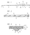
- Fig. 1 shows one preferred embodiment of an intra-line fishing rod of the invention.
- a butt rod 10 and a tip rod 12 of a rod tube are formed or molded by winding and baking a fiber-reinforce prepreg (This term is used in abroad sense including a thermoplastic resin) which is formed by impregnating high-strength fibers of carbon or the like with a thermosetting resin (e.g. an epoxy resin) or by mixing a thermoplastic resin (e.g. polyamide) with such high-strength fibers.
- the butt rod 10 and the tip rod 12 are serially connected together.
- a reel-mounting portion 16 is provided on the butt rod 10, and a reel 26 of the double bearing type is mounted on this reel-mounting portion 16.
- a fishline 28 is inserted into the interior or bore of the rod tube through a fishline-introducing portion 24 provided at a front end portion of the butt rod 10, and is passed therethrough to the exterior through a top guide 14 provided at the top of the tip rod 12.
- a front grip portion 20A is mounted on the butt rod 10 at the front side of the reel-mounting portion 16, and a rear grip portion 20B is mounted on the butt rod 10 at the rear side of the reel-mounting portion 16.
- a butt cap 22 is threadedly connected to the rear end of the butt rod 10.
- Reference numeral 18 denotes a trigger which receives an angler's finger during use.
- Fig. 2 is a longitudinal cross-section of a rear portion of the tip rod 12, and Fig. 3 is an enlarged view of a portion of the tip rod designated at III in Fig. 2.
- a plug 12E of metal or a synthetic resin is threaded into the rear end of the tip rod, and a guide ring G1 of a ceramics material is fixedly mounted on an inner peripheral surface of the plug 12E.
- a spiral guide 30 is formed integrally on the inner peripheral surface of that portion of the rod tube 12 disposed forwardly of the plug 12E.
- the spiral guide is one example, and annular guides independent of one another may be provided on this inner peripheral surface at predetermined intervals.
- the spiral guide may wind in either of a right direction and a left direction, and right-spiral guides and left-spiral guides may be combined.
- the guide may be provided over the entire length of the rod tube 12, or may be provided at part of the rod tube 12.
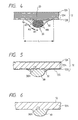
- the rod tube 12 has a pair of reinforcing layers 12A and 123 (in which the fibers are oriented generally in the circumferential direction) formed at its outer and inner peripheries, respectively, and the rod tube 12 also has a body layer 12H (in which the fibers are oriented generally in the axial or longitudinal direction) sandwiched between the two reinforcing layers 12A and 12B.
- the guide 30 comprises a synthetic resin as a matrix, and a reinforcing material HB of carbon fibers, ceramics fibers, glass fibers or metal fibers which are oriented mainly in the longitudinal direction of the guide 30.
- the outer side or surface of the guide 30 is straight as at 30H in Fig. 3 which shows a transverse cross-section thereof.
- the reinforcing material HB is provided mainly at a bulge region of the guide 30 for contact with the fishline, and is hardly provided at the outer side of the guide.
- the outer side portion of the guide 30 and its front an rear portions are defined by a synthetic resin layer JS made predominantly of a synthetic resin.
- the resin content in the region where the reinforcing material HB is provided is 30 ⁇ 60 wt.%, and this resin content is somewhat larger than the resin content of the rod tube. This facilitates the molding of the synthetic resin layer JS, and also prevents voids from developing in the inner surface of the guide 30.
- cushioning portions 32 of a synthetic resin are provided at the front and rear sides of the guide 30, respectively, and connect the guide 30 to the inner surface of the rod tube 12, the cushioning portion 32 being decreasing in thickness progressively away from the guide 30.
- the guide 30 is formed integrally with the rod tube in such a manner that the outer side of the guide 30 is slightly embedded in the reinforcing layer 12B. Therefore, those portions or regions 12b of the reinforcing layer 12B facing the outer side of the guide is smaller in thickness than the other regions.
- the reinforcing layer 12b, the reinforcing layer 12B adjacent to the guide, and the synthetic resin layer JS are smaller in bending modulus than the bulge region in which the reinforcing material HB is provided, and perform a cushioning function together with the cushioning portions 32, thereby preventing stresses from being concentrated when the rod tube is flexed.
- the synthetic resin, forming the synthetic resin layer JS and the cushioning portions 32 is of the same type as the synthetic resin forming the rod tube 12 (that is, if the rod tube is made of an epoxy resin, then the synthetic resin layer JS and the cushioning portions 32 are made of an epoxy resin), the strength of the integral structure is increased.
- the resin used for the guide 30 is of the type (e.g. a thermoplastic resin) which will not melt at the temperature of hot molding of the rod tube, reinforced fibers SL of the body layer 12H, which are oriented mainly in the axial direction, are prevented from meandering at the time of integrally joining the guide 30 to the rod tube-forming prepreg, since the outer side 30H of the guide 30 is straight as described above. This increases the strength of the rod tube.
- the resin used for the guide 30 is of the type (e.g. a thermoplastic resin) which will not melt at the temperature of hot molding of the rod tube, reinforced fibers SL of the body layer 12H, which are oriented mainly in the axial direction, are prevented from meandering at the time of integrally joining the guide 30 to the rod tube-forming prepreg, since the outer side 30H of the guide 30 is straight as described above. This increases the strength of the rod tube.
- the strength of the rod tube of this embodiment at the time of bending is 15 ⁇ 20% higher as compared with a construction in which any cushioning region (similar to the cushioning regions 32), and an outer side of a guide is not straight but is outwardly convex.
- Fig. 4 is a view similar to Fig. 3, but showing another preferred embodiment.
- a reinforcing material HB is distributed generally uniformly in a bulge region A1 (Although only a left half thereof is designated, a symmetrical right half is included) of a guide 30 for contact with the fishline and its inner portion, as described above. That portion of the guide containing the reinforcing material HB has a generally oval outer shape.
- the other portions of the guide 30, that is, regions A2 and A3 (provided at the front and rear portions of the guide 30) and inner portions thereof, define cushioning portions 32 made of a synthetic resin.
- the area covering the region A1 to A2 is convex away from the inner surface of the rod tube to secure a certain width of contact with the fishline (Most of the contact region is defined by the region A1), and the region A3 is concave toward the inner surface of the rod tube, and is progressively decreasing in thickness.
- the region A3 has the concave surface whose curvature is gentler than the average curvature of the area covering the regions A1 and A2, so that the width L of the guide 30 is increased, and also this is preferably more than about twice larger than the bulge region A1 (the right and left portions).
- a resin layer 33 serving as a cushioning layer is disposed outwardly of the guide 30, and is formed between a body layer 12H and a reinforcing layer 12B. Therefore, the concentration of stresses are prevented when the rod tube is flexed.
- a number of fibers of the reinforcing material are combined together into a bundle, and this bundle is impregnated with a thermosetting resin, and then twisting is imparted to the bundle.
- the resin melts and oozes out to form the cushioning portions 32 respectively at the front and rear sides of the guide 30.
- Fig. 5 shows a guide 30 formed by a material which will not melt during hot molding, such as a ceramics material, a metal material, a heat-resistant resin material and a heat-resistant composite material.
- An outer side or surface 30H of the guide 30 is straight, and is generally along an inner surface 12S of an inner reinforcing layer 12B of a rod tube 12.
- Cushioning portions 32, connecting the guide 30 to the rod tube, are provided at front and rear sides of the guide 30, respectively. These cushioning portions are formed by adding a small amount of a reinforcement to a synthetic resin. With this construction, the concentration of stresses is prevented when the rod tube is flexed. Since the outer side of the guide is straight, axially-extending fibers of a body layer 12H are prevented from meandering, and therefore the strength of the rod tube is increased.
- a number of guides 30 need to be spaced at short intervals along the rod tube so as to prevent the guide from being rubbed hard by the fishline, thus preventing part of the guide from being excessively worn.
- the provision of the reinforcing layers 12A and 12B may be omitted, in which case a layer of generally circumferentially-oriented fibers or a cloth in which some of fibers are oriented in the circumferential direction is usually included in the body layer 12H.
- Fig. 6 shows a guide 30 formed by a resin (e.g. a thermosetting resin) which melts at the temperature of hot molding of a rod tube 12 composed of a body layer.
- a resin e.g. a thermosetting resin
- an outer side or surface 30H of the guide 30 is straight so as to prevent axially-extending fibers of the rod tube from meandering.
- the guide 30 of the resin is liable to wear, and the guides 30 are spaced at short intervals along the rod tube (In the case of the spiral guide, the distance between the adjacent turns thereof is short). In that region closer to the tip rod, a larger flexure must be secured, and therefore the guide of the synthetic resin with a low flexural rigidity is preferably applied to such a region closer to the tip top.
- This portion of the rod tube is so designed that it is easily flexed for relieving purposes upon reception of a large load from the fishline, and therefore this portion is not so hard rubbed by the fishline as that portion of the fishing rod near to fishline-introducing portion, so that even the guide of the synthetic resin can smoothly guide the fishline.
- the guide 30 of the synthetic resin formed integrally with the rod tube 12 will not offer a large resistance to the flexing of the rod tube, and the concentration of stresses is prevented. Wear-resistant grains may be added in such an amount that the flexural rigidity is not adversely affected.
- the guide 30 may be formed utilizing the synthetic resin used in the prepreg for the rod tube 12.
- Fig. 7 shows a spiral guide 30 formed by a bundle of carbon fibers or the like.
- the guide 30 is formed on a rod tube 10' in a bulged manner, and a distal end portion of the guide 30 is wound tightly or densely over a predetermined length of a front end portion (used for connection) of the rod tube, thereby reinforcing this front end portion.
- the distal end portion of the guide 30 may be wound either as it is or with the fibers thereof disintegrated.
- the inner surface of the wound portion is tapering forwardly in the telescopic type, and is straight in the serially-connected type.
- the end portion of the rod tube (particularly, the joint end portion) which should originally be reinforce can be reinforced utilizing the spiral guide, so that the rod tube of a greater strength can be provided.
- the fishline may be caught by the end portion of the spiral guide 30 if this end portion is not suitably treated, and in such a case the resistance to the fishline may be increased, and the end portion of the guide 30 may be damaged.
- This reinforcement can, of course, be achieved using any other suitable material such as a prepreg sheet and a tape, or the above method and such a reinforcing method can be used in combination.
- Fig. 8 is a view explanatory of one method of producing an intra-line fishing rod.
- a tape 42 of a predetermined thickness is wound on a surface of a metal core 40 at predetermined intervals, and then a thin film 44 of polyethylene naphthalate (PEN) or polyethylene terephthalate (PET) which withstands a heating temperature is provided over the tape 42, and then a spiral guide G2 is windingly provided in a space formed by the wound tape 42.
- the thickness of the guide G2 and the thickness of the tape 42 are so determined that the outer side or surface of the guide 30 will generally contact an inner surface of a prepreg P1 (which constitutes a rod tube) to be wound on the outer surface.
- PEN polyethylene naphthalate
- PET polyethylene terephthalate
- the guide can be formed utilizing the constituent material of the rod tube. More specifically, when a reinforcing layer 12B as shown in Fig. 3 is to be formed on an inner surface of a rod tube, this inner reinforcing layer is formed not by a sheet-like prepreg but by a tape-like prepreg smaller in width than such a sheet.
- a guide protuberance can be formed on an inner surface of the rod tube, a tube of silicone or the like, having a spiral groove or independent annular grooves formed on an outer periphery thereof, is fitted on a metal core, or a heat-resistant resin tape is, for example, spirally wound on the metal core.
- the above-mentioned tape-like prepreg is wound on the tube or the tape to form the inner reinforcing layer 12B and the guide protuberance integrally with each other. Then, this assembly is baked according to a conventional method, and finally the tube or the resin tape is removed.
- the guide can be easily formed, and also in the tape-like prepreg, reinforced fibers can be arranged very long along the length of the tape in a generally continuous manner, and therefore in the formed guide, the reinforced fibers corresponding to the above reinforcement are generally continuous, so that the guide of a high strength is provided.
- the body layer in the tip rod can be formed by the material smaller in modulus of longitudinal elasticity as compared with the body layer in the butt rod or the intermediate portion of the fishing rod, so that the flexural rigidity of the tip rod can be smaller.
- the inner diameter of the tip rod can not be made so small in connection with its relation with the outer diameter of the fishline to be passed therethrough. Even in such a case, the tip portion can be flexible.
- the intra-line fishing rod in which the rod tube has the guide formed integrally with and projecting from the inner surface thereof, and the rod tube is prevented from being reduced in strength at those portions thereof where the guide is provided.
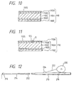
- Fig. 9 is a partly longitudinal cross-sectional view of a portion of a rod tube 110.
- the rod tube 110 comprises a rod tube body 110H composed of a prepreg formed by impregnating reinforced fibers (e.g. carbon fibers or glass fibers) with an epoxy resin or the like.
- a coating layer 110E is formed on an outer surface of the rod tube body 110H, and a very thin coating layer 110A of a synthetic resin, metal or ceramics is formed on an inner surface of the rod tube body 110H. Thanks to the provision of the very thin coating layer 110A, the inner surface of the rod tube is prevented from being scratched by a rough surface of a metal core when the baked rod tube is removed from the metal core, thereby preventing the reinforced fibers from damage.
- the rod tube body 110H is composed of three layers, that is, an intermediate layer 110C having the reinforced fibers oriented generally in the axial or longitudinal direction, and inner and outer layers 110B and 110D (which have the reinforced fibers oriented generally in the circumferential direction) formed respectively on the inner and outer surfaces of the intermediate layer 110C.
- This construction ensures a flexural rigidity of the rod tube, and also increases the strength of the rod tube to withstand impact to the rod tube.
- a fishline guide G as shown in Fig. 11 is not provided on an inner surface 110S of the very thin coating layer 110A at the rod tube 110 or a front region of the rod tube 110, and a fishline 112 contacts the inner surface 110S of the rod tube. Therefore, the inner surface 110S of the rod tube is formed into a mirror-like smooth surface in order to reduce a resistance of contact of the fishline and also to allow water drops to easily move upon contact of the fishline with the inner surface having the water drops deposited thereon, thereby reducing the resistance to the fishline.
- the very thin coating layer 110A is made not of a mixture material but of a synthetic resin
- a resin film is wound on a metal core so as to be disposed inwardly of the prepreg, and the metal core is removed after baking, and then the inner surface of the rod tube is polished into a mirror-like smooth surface by buffing, by applying vibrations to the rod tube after an abrasive material is introduced into the rod tube material, or by spraying a mixture of an abrasive material and the air or other liquid onto the inner surface of the rod tube material (In the latter two methods, the mirror surface-like smooth surface is formed by the relative motion between the abrasive material and the inner surface of the rod tube).
- the very thin coating layer 110A is composed of metal or ceramics
- a mirror-like thin film is formed by vapor deposition or the like on a film-like base having a mirror-like flat, smooth surface, and then this is wound on the metal core to be disposed inwardly of the prepreg.
- the metal core is removed after baking, and the rod tube having the mirror-like smooth surface is obtained.
- the mirror-like smooth surface can be obtained by polishing as described above.
- Metal and ceramics are harder than the synthetic resin, and has a wear resistance, and therefore are suited for forming the inner surface of the intra-line fishing rod through which the fishline is passed in contact with the inner surface.
- the surface of the metal core is finished into a mirror-like smooth surface with four triangular marks, and then the rod tube material is removed after baking, so that the inner surface of the rod tube is formed into a mirror-like smooth surface.
- the finish working has been effected with two or three triangular marks, and the surface roughness has been 10 ⁇ 5 ⁇ .
- the finish polishing with four triangular marks should be effected. This surface roughness is determined using the maximum height (indicated in JIS) as a reference, but the average roughness may be used if the measurement is easier.
- the inner surface layer of the rod tube is composed of a composite material (such as FRP which is reinforced by reinforced fibers, and comprises a resin as a matrix, or FRM which is reinforced by reinforced fibers, and comprises metal as a matrix), or where the inner surface of the rod tube is composed of a mixture resin layer containing ceramics particles, fluoroplastic particles or metal particles, the metal core is finished into a surface with four triangular marks as described above, and then the rod tube is removed after baking, so that the mirror surface-like smooth surface can be obtained.
- a composite material such as FRP which is reinforced by reinforced fibers, and comprises a resin as a matrix, or FRM which is reinforced by reinforced fibers, and comprises metal as a matrix
- the matrix is the relatively hard metal, and therefore the surface can be formed by the above polishing into the mirror surface-like smooth surface after molding.
- the composite material e.g. FRM
- the hard matrix constitutes the inner surface layer of the rod tube, wear by the fishline is prevented, and as a result damage to the fishline is prevented, and also the resistance to the fishline is reduced.
- the mirror-like smooth surface can also be formed on the inner surface of the rod tube by a method in which a resin film, having such a high melting temperature that it will not melt at a baking temperature of the prepreg, is preformed into a mirror surface-like smooth surface, and then it is baked together with the prepreg.
- the mirror surface-like smooth surface can be formed on the inner surface of the rod tube by a method in which the metal core is formed into a mirror surface-like smooth surface as described above, and then the resin film is wound so as to be dispose inwardly of the prepreg, and then the baking is effected.
- the mirror surface-like smooth surface can be formed on the inner surface of the rod tube by a method in which the mixture resin film is preformed into a mirror surface-like smooth surface, and then the resin film is baked together with the prepreg.
- a fluoroplastic resin such as a polymer of ethylene chloride trifluoride or ethylene chloride tetrafluoride, can be formed on the above mirror surface-like inner surface to thereby form a water-repellent surface in which the angle of contact of a waterdrop is not less than 110 degrees.
- an aluminum oxide surface layer can be formed on the inner surface, or a surface active agent can be applied to the inner surface, thereby imparting a hydrophilic property to the inner surface in which the contact angle is not more than 80 degrees.
- Water drops hardly deposit on the water-repellent surface, and even if the water drops deposit on such a surface, they move together with the fishline, so that the resistance to the fishline is small. Water drops are liable to be continuous with one anther on the hydrophilic surface to form a film of water thereon, so that the fishline is less liable to come into and out of the interface between the water drops and the air, and the fishline moves in the water film, so that the resistance to the fishline is reduced.
- Fig. 11 is an enlarged view similar to Fig. 10.
- a spiral fishline guide G or ring-shaped fishline guides G are projectingly formed on an inner surface of a rod tube.
- An inner surface GS of the fishline guide G for contact with a fishline is finished into a mirror surface-like smooth surface.
- An inner surface 110S of a very thin coating layer 110A is also finished into a mirror-like smooth surface.
- the fishline not only contacts the fishline guide G but also sometimes contacts the very thin coating layer 110A. Therefore, the very thin coating layer 110A is finished into the mirror-like smooth surface so as to further reduce the resistance to the fishline.
- this embodiment may be of such an arrangement that only the inner surface GS of the fishline guide G need to be finished into the mirror surface-like smooth surface.
- a tube of a deformable material e.g. silicone
- a spiral groove or ring-shaped grooves
- an elongate prepreg having reinforced fibers (e.g. carbon fibers) oriented mainly in a longitudinal direction, is provided along this groove, and then a very thin film of a synthetic resin is wound thereon, and further a prepreg for forming the rod tube is wound thereon, and then this assembly is pressurized and baked.
- the metal core is removed, and the tube of the deformable material (e.g. silicone) is deformed and removed.
- the rod tube having the fishline guide (guides) formed on and projecting from the inner surface thereof.
- the outer surface of the deformable tube, as well as the inner surface of the groove is beforehand finished into a mirror surface-like surface, and with this method the mirror-like smooth surfaces GS and 110S are automatically formed simultaneously with the molding of the rod tube.
- the rod tube body 110H may has any other suitable construction.
- the above-mentioned mirror-like smooth surface can be applied to an inner surface of other ordinary fishing rods other than the intra-line fishing rod, and also can be applied to an outer surface of any type of fishing rod. Dirt or stain is less liable to deposit on such a mirror-like smooth surface, and even if dirt deposits on the surface, it can easily removed. Therefore, this surface is clean, and a residual offensive smell due to dirt is eliminated, and the cause of cracks in the rod tube is eliminated, and therefore there can be provided the fishing rod of a high strength.
- the surface for contact with the fishline is formed into the mirror-like smooth surface. Therefore, the frictional resistance upon contact with the fishline is reduced, and even if the fishline contact the surface having water drops deposited thereon, the water drops are easily moved, so that the influence on the resistance to the fishline can be reduced. And besides, since the frictional resistance is small, rubbing will not develop, and frictional heat is small. Therefore, there can be provided the intra-line fishing rod in which the fishline and the inner surface of the rod tube are hardly damaged.
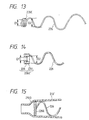
- Fig. 12 shows an intra-line fishing rod of the invention.
- An intermediate rod 212 is connected to a butt rod 210, and a tip rod 214 is connected to the intermediate rod 212.
- a top guide 216 is mounted on the tip top of the fishing rod.
- a reel-mounting device 218 is mounted on the butt rod 210, and a reel 220 is fixedly mounted on this device 218.
- a fishline-introducing portion 224 for introducing a fishline 222 into the fishing rod is provided at a front portion of the butt rod 210.
- the fishline 222 is introduced into the interior of a rod tube through this introducing portion, and is passed through the front portion of the butt rod, the intermediate rod and the tip rod, and is extended to the exterior through the top guide 216 at the tip top.
- one spiral guide 226 (an example of a continuous guide) is provided within the rod tube as shown in Fig. 13, or a plurality of spiral guides twisted in the same direction are provided within the rod tube, or a braid-like tube, composed of a pair of oppositely-twisted continuous guides, is inserted into the rod tube, or a guide member, having separate annular guide rings interconnected in a longitudinal direction by a bar-like member or the like, is inserted into the intermediate rod 212 or other rod, and is held or fixed.
- the size of the continuous guide is so determined that the outer periphery thereof can be held in contact with the inner surface of the rod tube. It is preferred from the viewpoint of maintenance of the guide that the guide can be removably inserted into and held by the rod tube.
- the front end portion of the spiral guide (continuous guide) 226 is wound tightly or densely to form an annular guide member 226E as shown in Fig. 13.
- This construction overcomes a disadvantage of the prior art in that the fishline becomes caught by this front end portion when the fishline is passed through the rod tube, and therefore the fishline can be smoothly passed through the rod tube with the construction of this invention.
- the inner diameter D1 of the annular guide member 226E is smaller than the inner diameter D2 of that portion of the spiral guide 226 disposed adjacent to this annular guide member 226E.
- the fishline When letting out the fishline as during casting, the fishline is usually passed through the rod tube while being shaken, and the fishline shaking within the rod tube contacts the inner surface thereof, and hence contacts water drops deposited on the inner surface, so that the resistance to the passage of the fishline is particularly increased.
- the passage bore is constricted by providing the annular guide member 226E, the fishline is less liable to contact the inner surface of the rod tube, and therefore the passage resistance is reduced.
- the annular guide member 226E shown in Fig. 13 is provided when the spiral guide 226 is made of metal. However, if the spiral guide is formed by a prepreg or the like, the annular guide member (which is provided at the front end portion), formed by a tightly-wound wire element, can be formed into a unitary tubular configuration.
- the pitch of the spiral winding is at least three times larger than the inner diameter of the rod tube, and is abut 10 ⁇ 50 mm depending on the inner diameter.
- the angle of the spiral winding is 45 degrees or more (that is, an angle approaching the longitudinal direction of the rod tube), thereby preventing the spiral guide from being deformed and damaged by the friction between the spiral guide and the fishline.
- the diameter of the wire element of the spiral guide 226 is preferably about 0.5 ⁇ 2 mm.
- the loop portions of the spiral guide may be not so extended in the longitudinal direction as in the above-mentioned guide having the separated annular guide rings interconnected by the bar-like member in the longitudinal direction, and that portion of the spiral guide interconnecting any two adjacent loop portions may be extended in the longitudinal direction.
- This spiral guide 226 may be inserted directly into the rod tube, or may be formed directly on the inner surface of the rod tube.
- the spiral guide 226 may be inserted into or formed on a cylindrical tubular member which is made of a prepreg, a synthetic resin or the like, and is inserted into the rod tube.
- an annular guide member (component part) 226E' or other shown in Figs. 14 and 16 may be formed integrally with the inner surface of the tubular member.
- the annular guide member can be formed on the inner surface of the front end portion of the tubular member, and a guide unit of the cartridge type having a spiral portion can be provided on the inner surface of the other portion.
- the annular guide member (component part) 226E' is attached to a front end of a spiral guide 226.
- This annular guide member may be fixedly or releasably attached to the spiral guide as described later with reference to Fig. 16.
- This annular guide member comprises a holder 230 of a synthetic resin, and a guide ring 228 of ceramics held on the inner periphery of the holder 230.
- the inner diameter D1' of the annular guide member is preferably smaller than the inner diameter D2 of the spiral guide.
- a longitudinally-extending slit may be formed in the outer periphery of the holder 230 of the annular guide member 226E', and with this slit, when the spiral guide 226 is inserted into the rod tube, the holder is slightly contracted radially inwardly, and the holder is held on the inner surface of the rod tube because of its radially-expanding effect, so that the spiral guide 226 is prevented from being easily moved.
- a rod tube 210' having a step portion 210D is provided, and the annular guide member 226E at the front end of the continuous guide 226 is held against the step portion 210D, thereby positioning and holding the spiral guide.
- a continuous guide has an annular guide member 226E at its front end, and also has similar annular guide members 226EB and 226EC provided intermediate the opposite ends thereof.
- the spiral guide is divided into guide elements 226A, 226B and 226C, and these guide elements are interconnected through the annular guide members 226EB and 226EC to form the continuous guide.
- the guide elements and the annular guide members may be completely fixedly connected together, or a cylindrical member may be fixedly secured to the end of each guide element, in which case this cylindrical member is releasably threaded on the outer periphery of the annular guide member.
- the end portion of the guide element may be wound into an annular configuration, in which case this annular portion is press-fitted on the outer periphery of the annular guide member, or the end of the guide element may be press-fitted into a recess formed in the annular guide member.
- the inner diameter of each annular guide member is smaller than the inner diameter of the guide element, the fishline is less liable to contact the inner surface of the rod tube and the guide element, so that the resistance to the letting-out of the fishline is reduced.
- the above continuous guides are formed by a prepreg formed by impregnating a bundle or a woven fabric of fibers (e.g. metal fibers, synthetic resin fibers or carbon fibers) with a synthetic resin such as an epoxy resin
- a wear-resistant material such as ceramics may be coated onto the inner surface of the continuous guide for guiding the fishline 222 so as to smoothly guide the fishline.
- the fibers are more oriented in the direction of movement of the fishline in the fiber bundle than in the woven fabric, and therefore with the prepreg of the fiber bundle, the fishline can be guided more smoothly.
- a noise prevention film is formed by bonding or the like on that surface of the continuous guide which contacts the inner surface of the rod tube when the continuous guide is inserted and held in the rod tube.
- the end portion of the spiral guide is liable to be damaged upon reception of a force from the fishline.
- the end portion is reinforced by a reinforcing material such as stainless steel, this end portion can be prevented from damage without the annular guide member as shown in Figs. 13 or 14; however, it is preferred that the annular guide member is provided in order to effect the smooth passage of the fishline. If a reinforcing member is provided along the entire length of the spiral guide, or is provided within the spiral guide, not only the end portion but also the other portion (that is, the whole) have the stable strength.
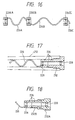
- Fig. 17 is a further embodiment of an annular guide member of the invention provided at the end of the spiral guide.
- the annular guide member is provided at the rear end of the spiral guide 226, and this annular guide member is in the form of a plug 232 of a synthetic resin having guide rings 228 of ceramics mounted therein and disposed respectively at front and rear portions thereof.
- the plug 232 also serves as a butt plug, and is adapted to be threaded into a rear end of an intermediate rod 212.
- the rear end portion of the spiral guide 226 is received in a spiral groove formed in the outer peripheral surface of the plug 232, and is fixed thereto by an adhesive or the like.
- the rear end portion of the spiral guide 226 is equal in outer diameter to the plug 232.
- the inner diameter of the guide ring 228 is smaller than the inner diameter of the spiral guide 226, and a similar effect as described above for the front end is achieved.
- Fig. 18 shows an assembly replacing the plug 232 of Fig. 17, and this assembly comprises a rear portion 232 and a front portion 232B.
- the front portion 232B is rotatable relative to the rear portion 232A.
- Fig. 19 shows an arrangement in which the front portion 232B and the spiral guide 226 are integrally connected together. More specifically, a wide spiral guide 226' is integrally molded with a front portion 232B'. As in the above embodiments, the inner diameter of the annular guide member (the inner diameter of a guide ring 228) is smaller than the inner diameter of the spiral guide 226'. Cushioning members 234 are bonded respectively to predetermined portions of the spiral guide 226' at the outer periphery thereof so as to prevent noises which would otherwise be produced, for example, because of the presence of a gap between the spiral guide and the inner surface of the rod tube. Alternatively, a coating film may be applied.
- a tubular member of a soft resin or rubber, such as a vinyl tube may be fitted on the spiral guide so as to achieve a cushioning effect.
- a plurality of tubular members each having a length corresponding to a pitch of the spiral winding may be provided at suitable intervals, or one continuous tubular member may be fitted on the spiral guide.
- the front portion 232B' has a polygonal (hexagonal) transverse cross-section as shown in Fig. 20. If this front portion has such a size that the corners of this polygon are slightly held against the inner surface of the rod tube when the spiral guide is inserted into the rod tube, or if the inner surface of the rod tube has a polygonal shape, the spiral guide 226' can be kept twisted a certain angle in a radially-expanding direction or a radially-contracting direction, so that the gap between the guide 226' and the inner surface of the rod tube can be adjusted.
- a coil spring member 236 is connected between a plug 232 and a spiral guide 226.
- the length of this structure from the plug 232 to the front end of the spiral guide 226 in its normal condition is slightly greater than the length of insertion of this structure into the rod tube.
- the spiral guide can be made of a shape memory alloy of Ni-Ti, or Cu-Zn-Al, or a shape memory resin. More specifically, the outer diameter of the spiral guide is kept large at an ordinary temperature during the fishing, and the outer diameter of the spiral guide becomes smaller at a predetermined time higher or lower than the ordinary temperature.
- the spiral guide made of such a shape memory alloy is to be inserted into the rod tube, the spiral guide is heated into the predetermined higher temperature or is cooled into the predetermined lower temperature, so that the spiral guide is reduced in outer diameter.
- the spiral guide is easily inserted into the rod tube. Thereafter, the temperature of the spiral guide rises to the ordinary temperature, the spiral guide is radially expanded to be held in firm contact with the inner surface of the rod tube, thereby preventing the shaking and noises.
- the shape memory alloy such as Ni-Ti alloy and the shape memory resin is excellent in corrosion resistance, and is suited for the fishing rod.
- the shape memory alloy or the shape alloy resin can be applied not only to the spiral guide but also to the above-mentioned continuous guides.
- the annular guide member is provided at the end of the continuous guide, and therefore the fishline is guided by the annular guide member, so that the fishline will not be caught by this end, and also the resistance to the passage of the fishline is prevented from increasing.
- the inner diameter of the annular guide member can be made smaller than the inner diameter of that portion of the continuous guide disposed adjacent to the annular guide member.
- Fig. 22 is a side-elevational view showing one step of a process of producing an intra-line fishing rod and Fig. 23 is an enlarged, cross-sectional view taken along the line XXIII-XXIII of Fig. 22, showing a condition after the winding of a prepreg and a thermosetting treatment are effected.
- a relatively thick winding member 320 made of a natural or an artificial material such as leather, silicone, Teflon (polytetrafluoroethylene) and rubber, is wound on a surface of a mandrel.
- the winding member 320 is in the form of a narrow strip, and is spirally wound on the mandrel at such a pitch that a spiral gap SP for receiving a wire-like fishline guide member 324 is formed between opposite side edges of the winding member 320. Then, a thin soft member 322 of a highly heat-resistant material, such as polyethylene naphthalate (PEN) and polyethylene terephthalate (PET), is applied to cover the spiral gap SP. In this embodiment, to facilitate the winding operation, the thin soft member 322 is wound over the entire surface of the thick winding member 320.
- PEN polyethylene naphthalate
- PET polyethylene terephthalate
- the fishline guide member 324 comprises carbon fibers or ceramics fibers with a large diameter, or a strap-like, fiber-reinforced prepreg, or a strap-like, fiber-reinforced prepreg reinforced by metal or ceramics (Such prepreg is similar to a prepreg for forming a rod tube). Then, fiber-reinforced prepregs 30 are wound several times thereon.
- the prepreg 330 is formed by impregnating reinforced fibers (e.g. carbon fibers) with a thermosetting resin or the like. Therefore, according to an ordinary method, this assembly is pressurized and heated to form the rod tube.
- a resin 326 flows from the fiber-reinforced prepregs 330 into gaps adjacent to the fishline guide member 324 during the hot molding, thereby integrally connecting the fishline guide member 324 to the rod tube.
- the fishline guide member 324 is received in the gap SP formed between the side edges 320e and 320f of the thick winding member 320, so that the thin soft member 322 is forced into this gap SP.
- the presence of this thin soft member 322 prevents the flowed resin from forming any corner or angle around the fishline guide member 324, so that the resin has a smooth surface, as shown in Fig.
- the mandrel is withdrawn, and the thick winding member 320 and the thin soft member 322 are removed. Part of the thin soft member 322 may remain.
- the fishline guide 324 is fixedly secured to the rod tube, and projects from the inner surface of the rod tube, and the surface of the fishline guide 324 is smooth, and can smoothly guide the fishline.
- the fishline guide member 324 comprises the single wire-like member, and is fixedly secured to the inner surface of the rod tube in a spiral, continuous manner.
- the thick winding members 320 also may be divided into a plurality of sections 320A, 320B ... 320H, in which case these sections are wound on the mandrel at suitable intervals to form a gap between opposed side edges of any two adjacent sections, and separate fishline guide members are provided in these gaps, respectively.
- the fishline guide member can be replaced by annular or ring-shaped guide members.
- the fishline guide member 324 may have, for example, a semi-circular transverse cross-section, in which case the fishline guide member is installed, with its flat side or surface facing the inner surface of the rod tube (that is, with the flat surface facing away from the surface of the mandrel).
- the fishline guide member 324 may be installed at part of the fishing rod, or may be installed generally over the entire length of the fishing rod.
- a strip-like winding member 320 as used in Fig. 4 is wound on a surface of a mandrel 310, with its opposite edge portions overlapping each other.
- a recess SP, formed at a step portion at the boundary between the overlapping portions and open portions of the winding member 320, is covered with a soft thin member as used in the first method, and then a release agent is coated onto this thin soft material.
- the other steps are similar to those of the first method.
- Fig. 25 is a view showing one step of a third method
- a groove SP' is preformed in a width-wise central portion of a thick, strip-like winding member 320', and this winding member 320' is wound tightly on a mandrel 310, with its opposite side edges held in contact with each other.
- Fig. 26 shows a transverse cross-section of the winding member 320' on an enlarged scale.
- the surface of the groove SP' is smooth.
- a release agent is coated onto the winding member 320', and then a fishline guide member as used in the above embodiments is provided in the groove SP', and then fiber-reinforced prepregs are wound thereon.
- the manufacture of the fishing rod proceeds, and a resin, flowed from the prepregs to those regions around the fishline guide, will not form any corner or angle since the groove SP' has the smooth surface.
- the winding member 320' is removed.
- the groove SP' is not formed in that portion of the winding member 320' disposed at the front end portion of the mandrel 310. The reason for this is that the fishline guide is not formed at the front end portion of the rod tube which is adapted to be connected to an associated rod tube.
- the depth of the groove SP' is not less than 0.3 mm, and the width thereof is suitably determined depending on the width of the fishline guide member, an inclination angle and so on.
- the thickness of the winding member 320' is not less than 0.5 mm.
- a thin soft member as described above is provided to cover the wound winding member so as to prevent the production of burrs due to a gap formed between the opposite side edges of the wound winding member. If the surface of the groove SP' is not smooth, the groove is covered with a soft thin member as described for the first and second methods.
- a sheet-like winding member 320" having grooves SP there may be used a sheet-like winding member 320" having grooves SP", and this sheet-like winding member is wound once on the mandrel (see Fig. 27).
- the size of the sheet is so determined that the opposite edges will not overlap each other. If there is formed a gap between the opposite edges, this gap is covered with a thin soft member as described above.
- the grooves SP" are interrupted at a region WT, and a water passage is formed on that portion of the inner surface of the rod tube corresponding to this interrupting region. In the above production methods, such a water passage can be formed by closing part of the gap SP or by interrupting the gap SP'.
- the intra-line fishing rod in which the fibers of the rod tube are prevented from meandering, and the fishline guide member stably projects from the inner surface of the rod tube, and the fishline can be smoothly guided, thus reducing the resistance to the passage of the fishline.
Landscapes
- Life Sciences & Earth Sciences (AREA)
- Environmental Sciences (AREA)
- Marine Sciences & Fisheries (AREA)
- Animal Husbandry (AREA)
- Biodiversity & Conservation Biology (AREA)
- Fishing Rods (AREA)
Claims (31)
- Angelrute mit Schnurinnenführung mit einem Durchgang, der sich entlang einer Längsachse erstreckt, um eine Angelschnur (28; 222) durch das Innere der Angelrute hindurchzuführen, wobei die Angelrute umfaßt:ein Rutenrohr (12; 210, 212, 214), das ein Kunstharz als Matrix umfaßt und durch verstärkte Fasern verstärkt ist, wobei das Rutenrohr innere und äußere Flächen aufweist, die sich entlang der Längsachse erstrecken, wobei die Innenfläche den Durchgang zum Durchführen der Angelschnur durch das Innere der Angelrute begrenzt;eine Angelschnurführung (226) zum Führen der Angelschnur in dem Rutenrohr entlang der Längsachse, wobei jene von der Innenfläche des Rutenrohrs hervorsteht, dadurch gekennzeichnet, daß das Rutenrohr mit zumindest einem zusätzlichen ringförmigen Führungselement (226E, 228) an seiner Innenfläche versehen ist, wobei der Innendurchmesser (D1) des ringförmigen Führungselements (226E, 228) kleiner als der Innendurchmesser (D2) eines benachbarten Abschnitts der Angelschnurführung (226) ist.
- Angelrute mit Schnurinnenführung gemäß Anspruch 1, dadurch gekennzeichnet, daß die Angelschnurführung von einer Mehrzahl von ringförmigen Führungsringen gebildet ist, die durch eine stangenförmiges Element verbunden sind.
- Angelrute mit Schnurinnenführung gemäß Anspruch 1, dadurch gekennzeichnet, daß die Angelschnurführung eine durchgehende Spiralführung (226) ist.
- Angelrute mit Schnurinnenführung gemäß einem der Ansprüche 1 bis 3, dadurch gekennzeichnet, daß das ringförmige Führungselement (226E) an einem Vorderende des Rutenrohrs angebracht ist.
- Angelrute mit Schnurinnenführung gemäß einem der Ansprüche 1 oder 4, dadurch gekennzeichnet, daß das ringförmige Führungselement (226E) fest mit der Spiralführung (226) verbunden ist.
- Angelrute mit Schnurinnenführung gemäß einem der Ansprüche 1 bis 5, dadurch gekennzeichnet, daß das ringförmige Führungselement einen Halter und einen Führungsring umfaßt.
- Angelrute mit Schnurinnenführung gemäß Anspruch 6, dadurch gekennzeichnet, daß der Halter aus einem Kunstharz gebildet ist.
- Angelrute mit Schnurinnenführung gemäß Anspruch 6 oder 7, dadurch gekennzeichnet, daß der Führungsring aus Keramik gebildet ist.
- Angelrute mit Schnurinnenführung gemäß einem der Ansprüche 6 bis 8, dadurch gekennzeichnet, daß der Halter ein Federhalter ist, der mit einem sich in Längsrichtung erstreckenden Schlitz versehen ist, um den Halter innerhalb des Rutenrohrs zu befestigen.
- Angelrute mit Schnurinnenführung gemäß einem der Ansprüche 1 bis 8, dadurch gekennzeichnet, daß das ringförmige Führungselement einheitlich mit der Innenfläche des Rutenrohrs geformt ist.
- Angelrute mit Schnurinnenführung gemäß einem der Ansprüche 3 bis 10, dadurch gekennzeichnet, daß das Rutenrohr mit einer Mehrzahl von ringförmigen Führungselementen versehen ist, die an der Vorderseite der Spiralführung und zwischen gegenüberliegenden Enden der Spiralführung vorgesehen sind.
- Angelrute mit Schnurinnenführung gemäß einem der Ansprüche 3 bis 5, dadurch gekennzeichnet, daß das ringförmige Führungselement an dem hinteren Ende der Spiralführung vorgesehen ist.
- Angelrute mit Schnurinnenführung gemäß Anspruch 12, dadurch gekennzeichnet, daß das ringförmig Führungselement von einem Stopfen mit Führungsringen gebildet ist.
- Angelrute mit Schnurinnenführung gemäß Anspruch 13, dadurch gekennzeichnet, daß der Stopfen aus Kunstharz hergestellt ist.
- Angelrute mit Schnurinnenführung gemäß Anspruch 13 oder 14, dadurch gekennzeichnet, daß die Führungsringe aus Keramik hergestellt sind.
- Angelrute mit Schnurinnenführung gemäß einem der Ansprüche 13 bis 15, dadurch gekennzeichnet, daß der Stopfen in das hintere Ende des Angelrohrs eingeschraubt werden kann.
- Angelrute mit Schnurinnenführung gemäß einem der Ansprüche 13 bis 16, dadurch gekennzeichnet, daß ein hinteres Ende der Spiralführung in einer Spiralnut aufgenommen wird, die auf der Außenseite des Stopfens gebildet ist.
- Angelrute mit Schnurinnenführung gemäß einem der Ansprüche 13 bis 17, dadurch gekennzeichnet, daß der Stopfen einen hinteren Abschnitt und einen vorderen Abschnitt umfaßt, wobei der vordere Abschnitt in bezug auf den hinteren Abschnitt drehbar ist.
- Angelrute mit Schnurinnenführung gemäß einem der Ansprüche 13 bis 17, dadurch gekennzeichnet, daß ein grobes Federelement zwischen dem Stopfen und der Spiralführung verbunden ist, um die Spiralführung in Vorwärtsrichtung zu drücken.
- Angelrute mit Schnurinnenführung gemäß einem der Ansprüche 13 bis 17, dadurch gekennzeichnet, daß die Spiralführung einheitlich mit dem Stopfen gebildet ist.
- Angelrute mit Schnurinnenführung gemäß einem der Ansprüche 15 bis 20, dadurch gekennzeichnet, daß eine Dämpfungseinrichtung zwischen der Spiralführung und dem Rutenrohr vorgesehen ist.
- Angelrute mit Schnurinnenführung gemäß einem der Ansprüche 13 bis 21, dadurch gekennzeichnet, daß der vordere Abschnitt des Stopfens eine Polygonform aufweist.
- Angelrute mit Schnurinnenführung gemäß einem der Ansprüche 1 bis 22, dadurch gekennzeichnet, daß die Angelschnurführung mit einem Geräuschdämpfungsfilm versehen ist.
- Angelrute mit Schnurinnenführung gemäß einem der Ansprüche 13 bis 23, dadurch gekennzeichnet, daß die Spiralführung aus Memory-Legierung hergestellt ist.
- Angelrute mit Schnurinnenführung gemäß einem der Ansprüche 13 bis 23, dadurch gekennzeichnet, daß die Spiralführung aus einem geformten Memory-Kunstharz hergestellt ist.
- Angelrute mit Schnurinnenführung gemäß einem der Ansprüche 1 bis 25, dadurch gekennzeichnet, daß die Angelschnurführung entfernbar in das Rutenrohr eingesetzt ist.
- Angelrute mit Schnurinnenführung gemäß Anspruch 3, dadurch gekennzeichnet, daß die Spiralführung eng oder fest gewickelt ist, um das ringförmige Führungselement zu bilden.
- Angelrute mit Schnurinnenführung gemäß Anspruch 3, dadurch gekennzeichnet, daß die Spiralführung einheitlich mit einem Rutenrohr auf dessen Innenseite gebildet ist.
- Angelrute mit Schnurinnenführung gemäß Anspruch 3, dadurch gekennzeichnet, daß die Spiralführung auf einem zylindrischen Rohrelement gebildet ist, wobei das Rohrelement in das Rutenrohr eingesetzt ist.
- Angelrute mit Schnurinnenführung gemäß einem der Ansprüche 3 bis 29, dadurch gekennzeichnet, daß die Spiralwicklung der Spiralführung 45° oder größer ist.
- Angelrute mit Schnurinnenführung gemäß einem der Ansprüche 1 bis 30, dadurch gekennzeichnet, daß der Durchmesser eines Drahtelements, das die Angelschnurführung bildet, 0,5 bis 2 mm ist.
Applications Claiming Priority (13)
| Application Number | Priority Date | Filing Date | Title |
|---|---|---|---|
| JP306930/94 | 1994-11-16 | ||
| JP30693094 | 1994-11-16 | ||
| JP06306930A JP3104838B2 (ja) | 1994-11-16 | 1994-11-16 | 中通し釣竿の製造方法 |
| JP7991395 | 1995-03-10 | ||
| JP7991395 | 1995-03-10 | ||
| JP79913/95 | 1995-03-10 | ||
| JP13599295 | 1995-05-10 | ||
| JP13599295A JPH08298900A (ja) | 1995-05-10 | 1995-05-10 | 中通し釣竿 |
| JP135992/95 | 1995-05-10 | ||
| JP14525995 | 1995-05-19 | ||
| JP14525995 | 1995-05-19 | ||
| JP145259/95 | 1995-05-19 | ||
| EP95118065A EP0712572B1 (de) | 1994-11-16 | 1995-11-16 | Angelrute mit Schnurinnenführung |
Related Parent Applications (1)
| Application Number | Title | Priority Date | Filing Date |
|---|---|---|---|
| EP95118065A Division EP0712572B1 (de) | 1994-11-16 | 1995-11-16 | Angelrute mit Schnurinnenführung |
Publications (3)
| Publication Number | Publication Date |
|---|---|
| EP0864253A2 EP0864253A2 (de) | 1998-09-16 |
| EP0864253A3 EP0864253A3 (de) | 1998-12-02 |
| EP0864253B1 true EP0864253B1 (de) | 2000-06-28 |
Family
ID=27466361
Family Applications (3)
| Application Number | Title | Priority Date | Filing Date |
|---|---|---|---|
| EP98109780A Expired - Lifetime EP0872181B1 (de) | 1994-11-16 | 1995-11-16 | Angelrute mit Schnurinnenführung |
| EP98109795A Expired - Lifetime EP0864253B1 (de) | 1994-11-16 | 1995-11-16 | Angelrute mit Schnurinnenführung |
| EP95118065A Expired - Lifetime EP0712572B1 (de) | 1994-11-16 | 1995-11-16 | Angelrute mit Schnurinnenführung |
Family Applications Before (1)
| Application Number | Title | Priority Date | Filing Date |
|---|---|---|---|
| EP98109780A Expired - Lifetime EP0872181B1 (de) | 1994-11-16 | 1995-11-16 | Angelrute mit Schnurinnenführung |
Family Applications After (1)
| Application Number | Title | Priority Date | Filing Date |
|---|---|---|---|
| EP95118065A Expired - Lifetime EP0712572B1 (de) | 1994-11-16 | 1995-11-16 | Angelrute mit Schnurinnenführung |
Country Status (3)
| Country | Link |
|---|---|
| US (2) | US6408562B1 (de) |
| EP (3) | EP0872181B1 (de) |
| DE (3) | DE69507771T2 (de) |
Families Citing this family (19)
| Publication number | Priority date | Publication date | Assignee | Title |
|---|---|---|---|---|
| DE69603420T2 (de) * | 1995-09-07 | 1999-11-25 | Daiwa Seiko, Inc. | Angelrute mit Schnurinnenführung |
| EP0832559A3 (de) * | 1996-08-28 | 1999-04-07 | Daiwa Seiko Inc. | Teleskopangelrute mit innerer Schnurführung |
| EP0829200A3 (de) * | 1996-09-15 | 1999-02-03 | Daiwa Seiko Inc. | Angelrute mit innerer Schnurführung |
| FR2765074B1 (fr) * | 1997-06-25 | 1999-08-06 | Paul Henri Viellard | Patins interieurs a un element tubulaire de canne a peche permettant au fil de peche de glisser sans effort a l'interieur du dit element et element equipe de ce patin |
| US6192615B1 (en) * | 1998-01-28 | 2001-02-27 | Daiwa Seiko, Inc. | Intraline fishing rod |
| WO2000016613A1 (en) * | 1998-09-24 | 2000-03-30 | Blanchette Paul J | Fishing rod guides, tops and hook keepers and method |
| US20040086704A1 (en) * | 2002-11-04 | 2004-05-06 | Schneider Terry L. | Polymer composite structure reinforced with shape memory alloy and method of manufacturing same |
| US7431981B2 (en) * | 2002-11-04 | 2008-10-07 | The Boeing Company | Polymer composite structure reinforced with shape memory alloy and method of manufacturing same |
| US6989197B2 (en) * | 2002-11-04 | 2006-01-24 | The Boeing Company | Polymer composite structure reinforced with shape memory alloy and method of manufacturing same |
| US7305792B2 (en) * | 2004-01-30 | 2007-12-11 | Daiwa Seiko, Inc. | Tip rod |
| US7533484B2 (en) * | 2004-06-21 | 2009-05-19 | Eagle Mountain Brokers, Inc. | Fishing pole, anti-wrap line guide for a fishing pole, and fishing rod |
| JP5047870B2 (ja) * | 2008-04-17 | 2012-10-10 | 株式会社日立製作所 | マスタ管理システム、マスタ管理方法、およびマスタ管理プログラム |
| KR101682242B1 (ko) * | 2009-03-30 | 2016-12-05 | 글로브라이드 가부시키가이샤 | 낚싯줄 가이드의 제조 방법 |
| JP5626762B2 (ja) * | 2010-03-31 | 2014-11-19 | 株式会社シマノ | 釣り糸用ガイド及び釣り竿 |
| US8813415B2 (en) * | 2010-03-31 | 2014-08-26 | Globeride, Inc. | Fishing line guide and method of manufacturing fishing line guide |
| US9504239B2 (en) | 2013-06-05 | 2016-11-29 | Scott Stender | Fishing rod with spiral fishing line guides |
| USD823428S1 (en) | 2014-04-08 | 2018-07-17 | Scott Stender | Fishing rod with spiral fishing line guides |
| WO2022005513A1 (en) * | 2020-07-02 | 2022-01-06 | Penicka Robert | Fishing rod and method for attaching line guides, tip tops and accessories to a rod blank |
| US20230217910A1 (en) * | 2022-01-13 | 2023-07-13 | WhyTangle LLC | Fishing storage device |
Family Cites Families (16)
| Publication number | Priority date | Publication date | Assignee | Title |
|---|---|---|---|---|
| US1595275A (en) * | 1924-10-04 | 1926-08-10 | Joel K White | Fishing rod |
| US2282618A (en) * | 1941-04-05 | 1942-05-12 | William H Stewart | Fishing rod |
| US2334646A (en) * | 1942-12-10 | 1943-11-16 | Russell C Price | Guideless jointed cane fishing pole |
| US2777239A (en) | 1954-07-01 | 1957-01-15 | Maurice E Cushman | Fishing rods |
| FR1541807A (fr) * | 1967-09-01 | 1968-10-11 | Perfectionnements aux cannes à pêche à parcours de fil intérieur | |
| FR1574826A (de) * | 1968-05-06 | 1969-07-18 | ||
| FR2123967A5 (de) * | 1971-02-05 | 1972-09-15 | Mecanique Halieutique Sa | |
| JPH078194B2 (ja) * | 1988-06-02 | 1995-02-01 | ダイワ精工株式会社 | 中通し竿用釣糸案内部材およびその製造方法 |
| JP3062284B2 (ja) | 1991-05-16 | 2000-07-10 | 株式会社シマノ | 中通し竿及びその製造方法 |
| JP3109169B2 (ja) | 1991-09-30 | 2000-11-13 | 東芝ライテック株式会社 | 光源装置 |
| JPH05268858A (ja) | 1992-03-30 | 1993-10-19 | Shimano Inc | 中通し竿及びその製造方法 |
| JPH05276853A (ja) * | 1992-04-02 | 1993-10-26 | Ryobi Ltd | 中通し釣竿およびその製造方法 |
| JP3017377B2 (ja) * | 1993-06-29 | 2000-03-06 | リョービ株式会社 | 中通し竿およびその製造方法 |
| JP3117050B2 (ja) * | 1993-10-08 | 2000-12-11 | ダイワ精工株式会社 | 中通し釣竿 |
| JP3027290B2 (ja) * | 1993-12-22 | 2000-03-27 | ダイワ精工株式会社 | 中通し釣竿 |
| TW351918U (en) * | 1994-02-25 | 1999-02-01 | Shimano Kk | Hollow fishing rod and its insert |
-
1995
- 1995-11-16 EP EP98109780A patent/EP0872181B1/de not_active Expired - Lifetime
- 1995-11-16 EP EP98109795A patent/EP0864253B1/de not_active Expired - Lifetime
- 1995-11-16 DE DE69507771T patent/DE69507771T2/de not_active Expired - Fee Related
- 1995-11-16 EP EP95118065A patent/EP0712572B1/de not_active Expired - Lifetime
- 1995-11-16 US US08/558,661 patent/US6408562B1/en not_active Expired - Lifetime
- 1995-11-16 DE DE69517711T patent/DE69517711T2/de not_active Expired - Fee Related
- 1995-11-16 DE DE69518551T patent/DE69518551T2/de not_active Expired - Fee Related
-
2001
- 2001-10-23 US US09/983,089 patent/US6543178B2/en not_active Expired - Fee Related
Also Published As
| Publication number | Publication date |
|---|---|
| US6543178B2 (en) | 2003-04-08 |
| EP0864253A2 (de) | 1998-09-16 |
| EP0712572A1 (de) | 1996-05-22 |
| EP0872181A3 (de) | 1998-11-04 |
| US6408562B1 (en) | 2002-06-25 |
| DE69507771D1 (de) | 1999-03-25 |
| US20020023380A1 (en) | 2002-02-28 |
| DE69518551D1 (de) | 2000-09-28 |
| DE69517711D1 (de) | 2000-08-03 |
| DE69507771T2 (de) | 1999-07-22 |
| DE69518551T2 (de) | 2001-01-11 |
| EP0712572B1 (de) | 1999-02-10 |
| EP0864253A3 (de) | 1998-12-02 |
| DE69517711T2 (de) | 2000-10-19 |
| EP0872181A2 (de) | 1998-10-21 |
| EP0872181B1 (de) | 2000-08-23 |
Similar Documents
| Publication | Publication Date | Title |
|---|---|---|
| EP0864253B1 (de) | Angelrute mit Schnurinnenführung | |
| EP1781095A1 (de) | Schnurführungen für angelruten | |
| US5488797A (en) | Inter-line fishing rod | |
| JP6396835B2 (ja) | 釣竿 | |
| US6243981B1 (en) | Inter-line fishing rod | |
| KR100230700B1 (ko) | 중통형 낚싯대(an interline fishing rod) | |
| JP3374951B2 (ja) | 中通し釣竿 | |
| JP3511562B2 (ja) | 釣 竿 | |
| JP3956233B2 (ja) | 釣糸ガイドを有する中通し釣竿 | |
| US6233862B1 (en) | Interline fishing rod | |
| JP3562682B2 (ja) | 中通し釣竿 | |
| JP3801554B2 (ja) | 中通し釣竿 | |
| JP3801555B2 (ja) | 中通し釣竿 | |
| US6108959A (en) | Interline fishing rod | |
| JP4395500B2 (ja) | 強度補強ブラシ及びバリ取り・研磨方法 | |
| JP3726932B2 (ja) | 釣糸ガイドを有する中通し釣竿の製造方法 | |
| JP4053400B2 (ja) | アウターガイド竿 | |
| JP3026535B2 (ja) | 中通し釣竿 | |
| JP3534376B2 (ja) | 中通し釣竿 | |
| JP4040771B2 (ja) | 釣竿 | |
| JP3638364B2 (ja) | 中通し竿用穂先竿 | |
| JPH08228642A (ja) | 中通し釣竿 |
Legal Events
| Date | Code | Title | Description |
|---|---|---|---|
| PUAI | Public reference made under article 153(3) epc to a published international application that has entered the european phase |
Free format text: ORIGINAL CODE: 0009012 |
|
| AC | Divisional application: reference to earlier application |
Ref document number: 712572 Country of ref document: EP |
|
| AK | Designated contracting states |
Kind code of ref document: A2 Designated state(s): DE FR GB IT |
|
| PUAL | Search report despatched |
Free format text: ORIGINAL CODE: 0009013 |
|
| AK | Designated contracting states |
Kind code of ref document: A3 Designated state(s): DE FR GB IT |
|
| 17P | Request for examination filed |
Effective date: 19990118 |
|
| GRAG | Despatch of communication of intention to grant |
Free format text: ORIGINAL CODE: EPIDOS AGRA |
|
| 17Q | First examination report despatched |
Effective date: 19990902 |
|
| GRAG | Despatch of communication of intention to grant |
Free format text: ORIGINAL CODE: EPIDOS AGRA |
|
| GRAH | Despatch of communication of intention to grant a patent |
Free format text: ORIGINAL CODE: EPIDOS IGRA |
|
| GRAH | Despatch of communication of intention to grant a patent |
Free format text: ORIGINAL CODE: EPIDOS IGRA |
|
| GRAA | (expected) grant |
Free format text: ORIGINAL CODE: 0009210 |
|
| AC | Divisional application: reference to earlier application |
Ref document number: 712572 Country of ref document: EP |
|
| AK | Designated contracting states |
Kind code of ref document: B1 Designated state(s): DE FR GB IT |
|
| REF | Corresponds to: |
Ref document number: 69517711 Country of ref document: DE Date of ref document: 20000803 |
|
| ITF | It: translation for a ep patent filed | ||
| ET | Fr: translation filed | ||
| PGFP | Annual fee paid to national office [announced via postgrant information from national office to epo] |
Ref country code: GB Payment date: 20001115 Year of fee payment: 6 |
|
| PGFP | Annual fee paid to national office [announced via postgrant information from national office to epo] |
Ref country code: FR Payment date: 20001130 Year of fee payment: 6 |
|
| PGFP | Annual fee paid to national office [announced via postgrant information from national office to epo] |
Ref country code: DE Payment date: 20001228 Year of fee payment: 6 |
|
| PLBE | No opposition filed within time limit |
Free format text: ORIGINAL CODE: 0009261 |
|
| STAA | Information on the status of an ep patent application or granted ep patent |
Free format text: STATUS: NO OPPOSITION FILED WITHIN TIME LIMIT |
|
| 26N | No opposition filed | ||
| PG25 | Lapsed in a contracting state [announced via postgrant information from national office to epo] |
Ref country code: GB Free format text: LAPSE BECAUSE OF NON-PAYMENT OF DUE FEES Effective date: 20011116 |
|
| REG | Reference to a national code |
Ref country code: GB Ref legal event code: IF02 |
|
| PG25 | Lapsed in a contracting state [announced via postgrant information from national office to epo] |
Ref country code: DE Free format text: LAPSE BECAUSE OF NON-PAYMENT OF DUE FEES Effective date: 20020702 |
|
| PG25 | Lapsed in a contracting state [announced via postgrant information from national office to epo] |
Ref country code: FR Free format text: LAPSE BECAUSE OF NON-PAYMENT OF DUE FEES Effective date: 20020730 |
|
| REG | Reference to a national code |
Ref country code: FR Ref legal event code: ST |
|
| REG | Reference to a national code |
Ref country code: FR Ref legal event code: ST |
|
| PG25 | Lapsed in a contracting state [announced via postgrant information from national office to epo] |
Ref country code: IT Free format text: LAPSE BECAUSE OF NON-PAYMENT OF DUE FEES;WARNING: LAPSES OF ITALIAN PATENTS WITH EFFECTIVE DATE BEFORE 2007 MAY HAVE OCCURRED AT ANY TIME BEFORE 2007. THE CORRECT EFFECTIVE DATE MAY BE DIFFERENT FROM THE ONE RECORDED. Effective date: 20051116 |