EP0850552B1 - Trägerband für bauelemente mit antistatischen eigenschaften - Google Patents
Trägerband für bauelemente mit antistatischen eigenschaften Download PDFInfo
- Publication number
- EP0850552B1 EP0850552B1 EP96928143A EP96928143A EP0850552B1 EP 0850552 B1 EP0850552 B1 EP 0850552B1 EP 96928143 A EP96928143 A EP 96928143A EP 96928143 A EP96928143 A EP 96928143A EP 0850552 B1 EP0850552 B1 EP 0850552B1
- Authority
- EP
- European Patent Office
- Prior art keywords
- strip portion
- cover
- carrier tape
- static dissipative
- pockets
- Prior art date
- Legal status (The legal status is an assumption and is not a legal conclusion. Google has not performed a legal analysis and makes no representation as to the accuracy of the status listed.)
- Expired - Lifetime
Links
- 230000003068 static effect Effects 0.000 title claims 5
- -1 alkyl methacrylate Chemical compound 0.000 claims 5
- 239000000463 material Substances 0.000 claims 5
- 239000000853 adhesive Substances 0.000 claims 4
- 230000001070 adhesive effect Effects 0.000 claims 4
- 238000000034 method Methods 0.000 claims 4
- 125000005250 alkyl acrylate group Chemical group 0.000 claims 3
- 239000007795 chemical reaction product Substances 0.000 claims 3
- CERQOIWHTDAKMF-UHFFFAOYSA-M Methacrylate Chemical compound CC(=C)C([O-])=O CERQOIWHTDAKMF-UHFFFAOYSA-M 0.000 claims 2
- VVQNEPGJFQJSBK-UHFFFAOYSA-N Methyl methacrylate Chemical group COC(=O)C(C)=C VVQNEPGJFQJSBK-UHFFFAOYSA-N 0.000 claims 2
- 125000000217 alkyl group Chemical group 0.000 claims 2
- CQEYYJKEWSMYFG-UHFFFAOYSA-N butyl acrylate Chemical group CCCCOC(=O)C=C CQEYYJKEWSMYFG-UHFFFAOYSA-N 0.000 claims 2
- SUPCQIBBMFXVTL-UHFFFAOYSA-N ethyl 2-methylprop-2-enoate Chemical compound CCOC(=O)C(C)=C SUPCQIBBMFXVTL-UHFFFAOYSA-N 0.000 claims 2
- 150000004820 halides Chemical class 0.000 claims 2
- 229920000515 polycarbonate Polymers 0.000 claims 2
- 239000004417 polycarbonate Substances 0.000 claims 2
- 125000005208 trialkylammonium group Chemical group 0.000 claims 2
- 239000011248 coating agent Substances 0.000 claims 1
- 238000000576 coating method Methods 0.000 claims 1
- 239000005038 ethylene vinyl acetate Substances 0.000 claims 1
- 229920001200 poly(ethylene-vinyl acetate) Polymers 0.000 claims 1
- 229920000728 polyester Polymers 0.000 claims 1
- 229920003048 styrene butadiene rubber Polymers 0.000 claims 1
Images

Classifications
-
- H—ELECTRICITY
- H05—ELECTRIC TECHNIQUES NOT OTHERWISE PROVIDED FOR
- H05K—PRINTED CIRCUITS; CASINGS OR CONSTRUCTIONAL DETAILS OF ELECTRIC APPARATUS; MANUFACTURE OF ASSEMBLAGES OF ELECTRICAL COMPONENTS
- H05K13/00—Apparatus or processes specially adapted for manufacturing or adjusting assemblages of electric components
- H05K13/003—Placing of components on belts holding the terminals
-
- Y—GENERAL TAGGING OF NEW TECHNOLOGICAL DEVELOPMENTS; GENERAL TAGGING OF CROSS-SECTIONAL TECHNOLOGIES SPANNING OVER SEVERAL SECTIONS OF THE IPC; TECHNICAL SUBJECTS COVERED BY FORMER USPC CROSS-REFERENCE ART COLLECTIONS [XRACs] AND DIGESTS
- Y10—TECHNICAL SUBJECTS COVERED BY FORMER USPC
- Y10S—TECHNICAL SUBJECTS COVERED BY FORMER USPC CROSS-REFERENCE ART COLLECTIONS [XRACs] AND DIGESTS
- Y10S428/00—Stock material or miscellaneous articles
- Y10S428/922—Static electricity metal bleed-off metallic stock
-
- Y—GENERAL TAGGING OF NEW TECHNOLOGICAL DEVELOPMENTS; GENERAL TAGGING OF CROSS-SECTIONAL TECHNOLOGIES SPANNING OVER SEVERAL SECTIONS OF THE IPC; TECHNICAL SUBJECTS COVERED BY FORMER USPC CROSS-REFERENCE ART COLLECTIONS [XRACs] AND DIGESTS
- Y10—TECHNICAL SUBJECTS COVERED BY FORMER USPC
- Y10T—TECHNICAL SUBJECTS COVERED BY FORMER US CLASSIFICATION
- Y10T428/00—Stock material or miscellaneous articles
- Y10T428/14—Layer or component removable to expose adhesive
- Y10T428/1424—Halogen containing compound
-
- Y—GENERAL TAGGING OF NEW TECHNOLOGICAL DEVELOPMENTS; GENERAL TAGGING OF CROSS-SECTIONAL TECHNOLOGIES SPANNING OVER SEVERAL SECTIONS OF THE IPC; TECHNICAL SUBJECTS COVERED BY FORMER USPC CROSS-REFERENCE ART COLLECTIONS [XRACs] AND DIGESTS
- Y10—TECHNICAL SUBJECTS COVERED BY FORMER USPC
- Y10T—TECHNICAL SUBJECTS COVERED BY FORMER US CLASSIFICATION
- Y10T428/00—Stock material or miscellaneous articles
- Y10T428/14—Layer or component removable to expose adhesive
- Y10T428/1471—Protective layer
-
- Y—GENERAL TAGGING OF NEW TECHNOLOGICAL DEVELOPMENTS; GENERAL TAGGING OF CROSS-SECTIONAL TECHNOLOGIES SPANNING OVER SEVERAL SECTIONS OF THE IPC; TECHNICAL SUBJECTS COVERED BY FORMER USPC CROSS-REFERENCE ART COLLECTIONS [XRACs] AND DIGESTS
- Y10—TECHNICAL SUBJECTS COVERED BY FORMER USPC
- Y10T—TECHNICAL SUBJECTS COVERED BY FORMER US CLASSIFICATION
- Y10T428/00—Stock material or miscellaneous articles
- Y10T428/14—Layer or component removable to expose adhesive
- Y10T428/1476—Release layer
-
- Y—GENERAL TAGGING OF NEW TECHNOLOGICAL DEVELOPMENTS; GENERAL TAGGING OF CROSS-SECTIONAL TECHNOLOGIES SPANNING OVER SEVERAL SECTIONS OF THE IPC; TECHNICAL SUBJECTS COVERED BY FORMER USPC CROSS-REFERENCE ART COLLECTIONS [XRACs] AND DIGESTS
- Y10—TECHNICAL SUBJECTS COVERED BY FORMER USPC
- Y10T—TECHNICAL SUBJECTS COVERED BY FORMER US CLASSIFICATION
- Y10T428/00—Stock material or miscellaneous articles
- Y10T428/14—Layer or component removable to expose adhesive
- Y10T428/149—Sectional layer removable
-
- Y—GENERAL TAGGING OF NEW TECHNOLOGICAL DEVELOPMENTS; GENERAL TAGGING OF CROSS-SECTIONAL TECHNOLOGIES SPANNING OVER SEVERAL SECTIONS OF THE IPC; TECHNICAL SUBJECTS COVERED BY FORMER USPC CROSS-REFERENCE ART COLLECTIONS [XRACs] AND DIGESTS
- Y10—TECHNICAL SUBJECTS COVERED BY FORMER USPC
- Y10T—TECHNICAL SUBJECTS COVERED BY FORMER US CLASSIFICATION
- Y10T428/00—Stock material or miscellaneous articles
- Y10T428/31504—Composite [nonstructural laminate]
- Y10T428/31507—Of polycarbonate
-
- Y—GENERAL TAGGING OF NEW TECHNOLOGICAL DEVELOPMENTS; GENERAL TAGGING OF CROSS-SECTIONAL TECHNOLOGIES SPANNING OVER SEVERAL SECTIONS OF THE IPC; TECHNICAL SUBJECTS COVERED BY FORMER USPC CROSS-REFERENCE ART COLLECTIONS [XRACs] AND DIGESTS
- Y10—TECHNICAL SUBJECTS COVERED BY FORMER USPC
- Y10T—TECHNICAL SUBJECTS COVERED BY FORMER US CLASSIFICATION
- Y10T428/00—Stock material or miscellaneous articles
- Y10T428/31504—Composite [nonstructural laminate]
- Y10T428/31786—Of polyester [e.g., alkyd, etc.]
- Y10T428/31797—Next to addition polymer from unsaturated monomers
-
- Y—GENERAL TAGGING OF NEW TECHNOLOGICAL DEVELOPMENTS; GENERAL TAGGING OF CROSS-SECTIONAL TECHNOLOGIES SPANNING OVER SEVERAL SECTIONS OF THE IPC; TECHNICAL SUBJECTS COVERED BY FORMER USPC CROSS-REFERENCE ART COLLECTIONS [XRACs] AND DIGESTS
- Y10—TECHNICAL SUBJECTS COVERED BY FORMER USPC
- Y10T—TECHNICAL SUBJECTS COVERED BY FORMER US CLASSIFICATION
- Y10T428/00—Stock material or miscellaneous articles
- Y10T428/31504—Composite [nonstructural laminate]
- Y10T428/31855—Of addition polymer from unsaturated monomers
- Y10T428/31935—Ester, halide or nitrile of addition polymer
Definitions
- This invention relates generally to carrier tapes for storing electronic components and for supplying those components seriatim to a machine. More specifically, this invention relates to carrier tapes having static dissipative properties and to a method by which such tapes are obtained.
- carrier tapes that are used to transport components from a component manufacturer to a different manufacturer that assembles the components into new products are well known.
- electronic components are often carried from a supply of such components to a specific location on a circuit board for attachment thereto.
- the components may be of several different types, including surface mount components. Particular examples include memory chips, integrated circuit chips, resistors, connectors, dual in-line processors, capacitors, gate arrays, etc.
- Such components are typically affixed to a circuit board that may later be incorporated into an electronic device.
- carrier tapes generally comprise an elongated plastic strip (often referred to as the carrier) that has a series of identical pockets formed at predetermined, uniformly spaced intervals along the length of the strip. The pockets are designed to receive an electronic component.
- a continuous cover (often referred to as a cover tape) is applied over the elongated strip to retain the components in the pockets.
- the carrier tape is fed to the robotic placement machine that strips the continuous cover tape from the carrier and removes the components from the pockets and places them onto the circuit board.
- Vibrations that occur during transport of the carrier tape may cause the stored components to contact the cover tape and/or the walls of the pocket.
- the resulting friction can generate static electricity.
- Removing the cover tape can also generate static electricity.
- Unfortunately however, the mere presence of a static electric field as well as subsequent electrostatic discharge can be extremely detrimental to sensitive electronic parts. This is particularly true of modern semiconductors and integrated circuits which may be degraded or destroyed by the build-up of static electricity in the workplace.
- Especially sensitive components can be severely affected by an electrical potential as small as 50 volts, yet the simple act of walking has been shown to triboelectrically generate a potential of 30,000 volts or more.
- Japanese Kokai Patent Application No. 4-214339 discloses a transparent conductive coating for a carrier.
- the coating comprises tin oxide antimony in a binder resin based on a vinyl chloride-vinyl acetate copolymer resin and an acrylic resin.
- Plastics used to make the carrier are polystyrene, polyvinyl chloride and polyethylene.
- the carrier may be used in conjunction with a cover tape that includes a base sheet comprised of a polyester, and a heat seal resin layer comprised of a ethylene-vinyl acetate copolymer resin, and containing an antistatic agent such as a nonionic surfactant.
- the presence of the tin oxide compound can cause an increase in haze and adversely affect the ability to form a good bond between the cover tape and the carrier.
- Japanese Kokai Patent Application No. 5-42969 discloses a 7,7,8,8-tetracyanoquinodimethane conductive filler dispersed in an acrylic binder to provide a transparent conductive coating for a plastic carrier tape base sheet (e.g., vinyl chloride, polystyrene or polyethylene).
- a plastic carrier tape base sheet e.g., vinyl chloride, polystyrene or polyethylene.
- EP-A-0 219 315 discloses a carrier tape comprising a static dissipative strip portion provided with a coating of an acrylate monomer-oligomer mixture containing an alkylether triethyl ammonium sulfate, which may be blended with an adhesive.
- the static dissipative coating should be applied to the inside surface; i.e., the surface which faces the interior of the component-carrying pocket.
- This surface usually carries an adhesive so as to form an adhesive bond with the carrier.
- U.S. Patent No. 4,902,573 Jonas et al. notes that applying an antistatic material to the adhesive may cause a loss of adhesion. Jonas et al. further observe that the adhesive is often heat-activated and that the heat which is used to form a bond with the carrier may reduce the antistatic properties.
- the antistatic agent incorporated into the adhesion layer has bled onto the inner surface of the cover tape and invited unstable sealing and many troubles due to poor sealing; moreover, the antistatic effect has decreased with the lapse of time, has been greatly affected by the conditions under which the package was used, i.e., temperature and humidity, particularly humidity, and has significantly decreased under a low humidity such as 10% R.H.; thus, no sufficient effect has been obtained.
- the incorporation of a conductive material into an adhesion layer has been technically difficult, because the adhesion layer has been formed by laminating an extruded film or the like to an outer layer; moreover, the incorporation has significantly reduced the transparency of the resulting cover tape, making the cover tape usability questionable.
- the coating of a conductive material on an adhesion layer has not been effected in fact, because the selection of a binder stably bondable to the carrier tape has been difficult, and because the adhesion layer is covered and hidden by the coating.”
- Miyamoto et al. disclose a multilayer cover tape in which a biaxially oriented polyester, polypropylene or nylon layer is adhesively bonded to a polyolefin intermediate layer.
- the opposite surface of the polyolefin layer is coated with a conductive powder-loaded, transparent, thermoplastic, heat-sealing adhesion layer that bonds to the carrier.
- the cover tape is removed from the carrier, the polyolefin intermediate layer fails cohesively, a portion of it remaining adhesively bonded to the carrier. The residue that remains on the carrier could attract dirt and other contaminants and would make it difficult to recycle the carrier for reuse.
- a carrier tape that includes a static dissipative carrier and an adhesively bonded cover tape which preferably is also static dissipative.
- the carrier includes a static dissipative coating, it should not reduce or impair adhesion to the cover tape.
- the static dissipative coating will promote adhesion to the cover tape such that the cover tape adheres firmly to the carrier without a significant change in adhesion over time, and such that a heat bondable cover tape could be adhered to the carrier at a lower temperature. If the adhesion decreases over time, the cover tape could come loose prematurely with a loss of the stored components. If the adhesion increases over time, it may be difficult to remove the cover tape from the carrier. Similarly, there should be no significant loss of static dissipative properties over time and under typical manufacturing and storage conditions. The entire construction should also remain sufficiently transparent that the electronic components transported by the carrier tape are visible without removing the cover tape.
- the invention relates to a flexible carrier tape for storage and delivery of electronic components by an advancement mechanism as defined by the features of claim 1.
- the carrier tape comprises a static dissipative strip portion having a top surface, a bottom surface opposite the top surface, a plurality of aligned pockets for carrying the components, the pockets being spaced along the strip portion and opening through the top surface thereof.
- the pockets generally include at least one side wall that adjoins and extends downwardly from the strip portion, and a bottom wall that adjoins the side wall.
- the pockets more preferably include four side walls each at generally right angles with respect to each adjacent side wall.
- each of the pockets is essentially identical and are equally spaced along the strip portion.
- the strip portion further has first and second parallel longitudinal edge surfaces, and preferably at least one of the edge surfaces includes a plurality of equally spaced holes for receiving the advancement mechanism (for example, a sprocket).
- the strip portion further includes thereon a coating of a static dissipatingly effective amount of a static dissipative material.
- the static dissipative material consists essentially of a polymer (e.g., a terpolymer) of an alkyl acrylate (preferably butyl acrylate), an alkyl methacrylate (preferably methyl methacrylate), and a trialkyl ammonium halide alkyl methacrylate (preferably 2-(trimethyl ammonium chloride) ethyl methacrylate).
- the carrier tape also includes a cover (preferably one that is static dissipative) that is releasably and adhesively bonded to the top surface of the strip portion, extends along the strip portion, and covers the pockets.
- a cover preferably one that is static dissipative
- the strip portion is formed from polycarbonate
- the cover is formed from polyester
- the adhesive that bonds the cover to the strip portion is a heat bondable material such as an ethylene-vinyl acetate copolymer or a styrene-butadiene block copolymer.
- the static dissipative coating used on the strip portion does not adversely affect adhesion to the cover, even under strenuous conditions of high temperature and humidity.
- the static dissipative material actually promotes adhesion to a heat bondable cover and, as a result, permits such a cover to be bonded to the strip portion at lower temperatures than could be used if no static dissipative coating were present or if other static dissipative materials were used.
- the carrier tape remains sufficiently transparent to pennit visual inspection of components carried by the carrier tape without removing the cover.
- the invention also relates to a method of reducing the temperature at which a heat bondable cover is bonded to polycarbonate carrier by using a layer of the acrylic polymer on the strip portion. This method is defined by the features of claim 10.
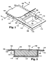
- a carrier tape according to the invention is shown in FIGS. 1 and 2.
- the illustrated carrier tape is useful for the storage and delivery of components (especially electronic components) by an advancement mechanism.
- a flexible carrier tape 100 has a carrier or strip portion 102 defining a top surface and a bottom surface opposite the top surface.
- Strip portion 102 includes longitudinal edge surfaces 104 and 106, and a row of aligned advancement holes 108 and 110 formed in and extending along one, and preferably both, edge surfaces.
- Advancement holes 108 and 110 provide a means for receiving an advancement mechanism such as the teeth of a sprocket drive for advancing carrier tape 100 toward a predetermined location.
- each pocket 112 is formed in and spaced along strip portion 102, the pockets opening through the top surface of the strip portion.
- each pocket is usually essentially identical to the other pockets. Typically, they are aligned with each other and equally spaced apart.
- each pocket includes four side walls 114, each at generally right angles with respect to each adjacent wall. Side walls 114 adjoin and extend downwardly from the top surface of the strip portion and adjoin bottom wall 116 to form pocket 112. Bottom wall 116 is generally planar and parallel to the plane of strip portion 102.
- bottom wall 116 may include an aperture or through hole 117 that is of a size to accommodate a mechanical push-up (e.g., a poke-up needle) to facilitate removal of component 118 (such as an electronic component) that is stored in pocket 112.
- Aperture 117 may also be used by an optical scanner to detect the presence or absence of a component within any given pocket.
- aperture 117 may be useful in applying a vacuum to the pocket to permit more efficient loading of the pockets with components.
- Pockets 112 may be designed to conform to the size and shape of the components that they are intended to receive. Although not specifically illustrated, the pockets may have more or less side walls than the four that are shown in the preferred embodiment. In general, each pocket includes at least one side wall that adjoins and extends downwardly from strip portion 102, and a bottom wall that adjoins the side wall to form the pocket. Thus, the pockets may be circular, oval, triangular, pentagonal, or have other shapes in outline. Each side wall may also be formed with a slight draft (i.e., a 2° to 12° slant toward the center of the pocket) in order to facilitate insertion of the component, and to assist in releasing the pocket from a mold or forming die during fabrication of the carrier tape.
- a slight draft i.e., a 2° to 12° slant toward the center of the pocket
- the depth of the pocket can also vary depending on the component that the pocket is intended to receive.
- the interior of the pocket may be formed with ledges, ribs, pedestals, bars, rails, appurtenances, and other similar structural features to better accommodate or support particular components.
- two or more columns of aligned pockets could also be formed along the length of the strip portion in order to facilitate the simultaneous delivery of multiple components. It is expected that the columns of pockets would be arranged parallel to each other with pockets in one column being in aligned rows with the pockets in the adjacent column(s).
- Strip portion 102 may be formed of any polymeric material that has a sufficient gauge and flexibility to permit it to be wound about the hub of a storage reel.
- strip portion 102 is optically clear by which it is meant that it is sufficiently transparent to permit components stored within the pockets to be visually inspected without removing elongated cover 120 (described more fully hereinbelow).
- a variety of polymeric materials may be used including, but not limited to, polyester (e.g., glycol-modified polyethylene terephthalate), polycarbonate, polypropylene, polystyrene, and acrylonitrile-butadiene-styrene.
- polyester e.g., glycol-modified polyethylene terephthalate
- polycarbonate polypropylene
- polystyrene polystyrene
- acrylonitrile-butadiene-styrene acrylonitrile-butadiene-styrene.
- the use of polycarbonate is particularly preferred because of its excellent transparency,
- Strip portion 102 includes a layer or coating 119 of a static dissipative material.
- the static dissipative coating allows an electric charge to dissipate throughout the carrier tape and preferably to the ground. This feature helps prevent damage to components contained within the carrier tape due to an accumulated static electric charge.
- Static dissipative coating 119 is applied to the interior surfaces of pocket side walls 114 and pocket bottom walls 116; i.e., the surfaces which face the component carried by pocket 112.
- Static dissipative coating 119 may also be (and preferably is) applied to longitudinal edge surfaces 104 and 106 of strip portion 102.
- Static dissipative coating 119 may also be applied to the bottom surface of strip portion 102 (e.g., the exterior surfaces of the pocket side walls and bottom wall).
- the coating should also be dry (i.e., non-tacky) to the touch.
- Static dissipative coating 119 is provided by a static dissipative material.
- a static dissipative material Those materials which are useful in the invention may be described as polymeric surfactants.
- the static dissipative material consists essentially of a polymer (e.g., a terpolymer) of an alkyl acrylate (e.g., butyl acrylate), an alkyl methacrylate (e.g., methyl methacrylate), and a trialkyl ammonium halide alkyl methacrylate (e.g., 2-(trimethyl ammonium chloride) ethyl methacrylate).
- a very useful commercially available material is RS-811 from Nippon Nyukazi Co., Ltd. (Japan) which has a glass transition temperature of about 200° C, and a surface resistivity of about 10 9 ohms/square at 23° C and 65 % relative humidity.
- the static dissipative material is typically provided in the form of a solution for easy application to the carrier.
- Solvents for forming the solution should be ones in which the static dissipative material will dissolve or can be emulsified.
- the solvents should also wet the strip portion. While water/methanol solvent systems may be used, water/ethanol solvent systems are particularly preferred, useful examples of which contain about 80 - 95 % ethanol and, correspondingly about 20 - 5% water.
- the static dissipative material is added to the solvent so as to provide a static dissipatingly effective amount thereof, preferably about 1.0 to 3.0 wt. % static dissipative material, more preferably about 1.2 to 2.0 wt. %.
- the layer of static dissipative material is preferably about 0.1 to 1.0 ⁇ m thick, more preferably about 0.2 to 0.4 ⁇ m thick.
- the unitary carrier tape 100 also includes an elongate cover 120 (sometimes referred to herein as a cover tape).
- Cover 120 is applied over the pockets of the carrier tape to retain the components therein. Cover 120 can also protect the components from dirt and other contaminants that could invade the pockets.
- cover 120 is flexible, overlies part or all of pockets 112, and is disposed between the rows of advancement holes 108 and 110 along the length of strip portion 102. Cover 120 is releasably secured to the top surface of strip portion 102 so that it can be subsequently removed to access the stored components.
- cover 120 includes parallel longitudinal bonding portions 122 and 124 that are bonded to longitudinal edge surfaces 104 and 106, respectively, of strip portion 102.
- a pressure sensitive adhesive such as an acrylate material, or a heat-activated adhesive such as an ethylene-vinyl acetate copolymer or a styrene-butadiene block copolymer, may be used to adhere the cover to edge surfaces 104 and 106.
- Typical adhesive thickness is about 30 ⁇ m.
- the use of a heat-activated adhesive is especially preferred for forming a good seal to the strip portion.
- the cover may be primed to promote adhesion of the adhesive layer to the cover.
- cover 120 removes from strip portion 102 without leaving any visible adhesive or other kind of residue on the strip portion. Such residues could attract dirt or other contaminants and could make it difficult to recycle the carrier for reuse.
- cover 120 should be modified to be static dissipative.
- Cover 120 may include a static dissipative material, such as carbon black, vanadium pentoxide, or a surfactant that is either interspersed within the polymeric material or is subsequently coated onto the cover.
- the static dissipative material may also be incorporated into the adhesive that bonds cover 120 to strip portion 102 so long as it does not adversely affect adhesion. It is desirable for the cover to be optically transparent as discussed for strip portion 102.
- Cover 120 may be formed of a wide variety of polymeric materials, including those which may be used to provide strip portion 102. Polyesters (in particular, polyethylene terephthalate based polyesters) are especially preferred.
- An example of a useful, commercially available static dissipative cover tape is DENKA ALS-AS (Denki Kagaku Kogyo Co. Ltd., Japan). Typical cover thicknesses (not including any adhesive) are about 25 ⁇ m.
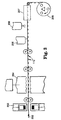
- the carrier tapes of the invention are made by shaping the pockets in a sheet of polymeric material and winding the carrier tape onto a reel to form a roll. More specifically, and with reference to the schematic view of FIG. 3 as an example, a web 200 of a flexible thermoplastic polymer is supplied as a preformed roll, as a preformed sheet, by direct extrusion, or by continuous injection molding to a mold or die 204 (which may be a pair of matched male and female dies) that thermoform the web. Mold 204 thermoforms the pockets to the desired size and shape (allowing for any subsequent shrinkage upon cooling). The dimensions of the incoming polymeric web will be determined by the gauge and width of the carrier tape that is to be formed.
- thermoforms and “thermoforming” is meant a process that relies on the use of both heat and pressure to deform a thermoplastic material.
- the heat may be provided by the mold itself, a preheater 202, or an extruder (not shown specifically).
- polymeric web 200 is heated sufficiently to permit thermoforming.
- the temperature to which the polymeric web must be heated varies over a broad range (i.e., about 93-288°C (200-550°F)) depending on the gauge and type of material that is being thermoformed as well as the speed of the manufacturing line.
- the applied pressure is sufficient to permit a high quality replication of the mold or die pattern and may be provided by, for example, the force the mold exerts upon web 200 when the mold closes, or by the application of a vacuum that urges the web to deform over a male die or draws the web into a female die (i.e., vacuum thermoforming).
- Web 200 is typically cooled after thermoforming, which can be accomplished by air cooling, fans, a water bath or a cooling oven until the thermoplastic polymer solidifies.
- thermoforming is a process that is familiar to those of ordinary skill in the art and is described in various references such as Encyclopedia of Polymer Science and Engineering , volume 16, second edition, published by John Wiley & Sons, 1989, which discusses different thermoforming processes and the use of roll-fed, sheet-fed, in-line extrusion, and continuous web-fed systems. All of these can be employed to manufacture the carrier tapes of the invention, as can different thermoforming tools that are described in the technical literature. such as flat forming and rotary devices, these devices being available for use with various thermoforming techniques such as matched mold forming, plug-assist forming, basic vacuum forming, and pressure forming.
- the advancement holes are subsequently formed in a separate operation such as punching by punch 205.
- the static dissipative coating may be applied by a variety of techniques including dipping, brushing or spraying (e.g., air spraying or ultrasonic spraying), spraying being illustrated schematically in FIG. 3 as station 206.
- coated web 200 should be dried at a temperature and for a time sufficient to evaporate any solvents or carrier liquids so as to form a dry coating on the web. This can be easily accomplished by passing the coated web through a drying oven 207.
- the carrier tape is then wound (either concentric or level windings) about the core of reel 208 to form a supply roll for storage until the carrier tape is loaded with components.
- a component loader 210 may fill pockets 112 with components 118, cover 120 is delivered from a roll 212 and secured by an applicator 214 to the longitudinal edge surfaces of the carrier tape strip portion, and the loaded carrier tape is wound about a core or reel 216 for storage or delivery.
- the applicator is heated.
- a bond can be formed at a temperature between room temperature (about 25° C) and about 220° C, more preferably between room temperature and about 200° C, and most preferably between room temperature and about 180° C.
- Carrier tape 100 is advanced by sprockets 209 and 211.
- the carrier tape is unloaded as shown in the schematic example of FIG. 5, which illustrates a carrier tape 100 in combination with a robotic placement machine 218.
- Supply reel 216 provides carrier tape 100.
- a stripper assembly 220 peels cover 120 from carrier tape 100 around a stripper block 222, which assists in preventing the stripper assembly from pulling the carrier tape away from its designated path.
- Carrier tape 100 is advanced by a sprocket 224, to move the carrier tape toward robotic placement machine 218. As each successive component reaches the desired pick-up point, the robotic placement machine grasps the component (either manually or by suction) and places it, for example, on a circuit board in the appropriate location.
- the carrier tapes of the invention are particularly useful in the electronics industry for transporting and delivering surface mount electronic components such as memory chips, integrated circuit chips, resistors, connectors, dual in-line processors, capacitors, gate arrays, etc.
- the carrier tapes may be used to transport other components such as small springs, clips, and the like.
- Static dissipative strip portions were prepared by applying a water/alcohol solution of a static dissipative material to a strip portion having component pockets and removing the solvent. More specifically, a static dissipative strip portion was prepared by spray coating a solution comprising 1.5 % solids by weight of RS-811 terpolymer (Nippon Nyukazai Company, Ltd., Japan) in a water:ethanol (1:10 w/w) solvent mixture onto a polycarbonate web (3M brand #2703, 3M Company, St. Paul, Minnesota) measuring 8 millimeters (mm) wide and 0.25 mm thick, and then drying at 65° C for two minutes. (The water used to prepare the water/ethanol mixture was first purified by ion exchange.) The thickness of the dried coating was calculated to be about 0.3 ⁇ m (microns).
- a cover tape was sealed to the strip portion using heat and pressure to form a carrier tape. More specifically, a static dissipative, adhesive-coated cover tape, DENKA ALS-AS (Denki Kagaku Kogyo Co., Ltd., Japan), was adhered to a strip portion using a MT-30 Taper (Systemation engineered Products, Inc., New Berlin, Wisconsin) operating in the reciprocating mode with pressure of 1,78 N/cm 2 (10 psi), 2.5 strikes, a dwell time of 0.4 seconds per strike, and a temperature of 180° C (indexing 32 mm of carrier tape per strike). The cover tape was 5.4 mm wide.
- DENKA ALS-AS Diski Kagaku Kogyo Co., Ltd., Japan
- RH relative humidity
- the transparency and haze of strip portions prepared as described above in the "General Preparation" were evaluated to determine their suitability for visual inspection procedures without removing a subsequently applied cover tape. More specifically, the transparency and haze were measured using Japanese Industrial Standard test method JIS-K-7105 (published March 1, 1981). A transparency value of greater than 85% is desired, with a value of greater than 90% being preferred. A haze value of less than 5% is desired, with a value of less than 1% being preferred.
- the force required to peel the cover tape from the strip portion was measured using Japanese Industrial Standard test method JIS-C-0806 (published January 1, 1990).
- the cover was peeled from the strip portion at an angle of 180° at a continuous peel rate of 300 millimeters/minute. Five samples were tested and the results were used to calculate the average peel adhesion. In general, a peel adhesion of 0,1 - 0,69 N/cm 2 (10 to 70 grams force) is desirable, with 0,2 - 0,59 N/cm 2 (20 to 60 grams force) being preferred.
- the cover tape should remove uniformly. A raspy peel (i.e., areas of high and low adhesion) is undesirable.
- the cover tape should also remove without leaving visible adhesive residue on the strip portion
- the properties of surface resistivity, peel adhesion, and static build-up were also measured after various aging protocols for some samples.
- the aging protocols included one or more of the following conditions: A) aging at 23° C; B) aging at 40° C; C) aging at 60° C; D) aging at 40° C/ 80% RH; and E) aging at 50° C / 95 % RH.
- For surface resistivity measurements the strip portion, free of electronic components and cover tape, was aged and then tested as described above.
- peel adhesion measurements the strip portion with the cover tape sealed to it was aged and then tested as described above.
- static build-up measurements the strip portion, free of electronic components and cover tape, was aged and then loaded with electronic chips. The cover tape was then sealed to the strip portion.
- preferred (and more preferred) values are as follows: tor either 1000 hours at condition A or 100 hours at condition C: less than 1E11 Ohms/square (less than 3E10 Ohms/square); and for 200 hours at condition D: less than 3E11 Ohms/square (less than 1E11 Ohms/square).
- preferred (and more preferred) values are as follows: for 1000 hours at condition A: 0.10 to 0.69N (10 to 70 grams force) (0.20 to 0.59N (20 to 60 grams force)); for 100 hours at condition C: 0.10 to 0.78N (10 to 80 grams force) (0.20 to 0.69N (20 to 70 grams force)); and for 200 hours at condition D: 0.10 to 0.69N (10 to 70 grams force) (0.20 to 0.59N (20 to 60 grams force)).
- a static dissipative strip portion was prepared as described above in the "General Preparation.”
- the strip portion was tested as described above for surface resistivity, both initially and after various aging protocols, and for initial transparency and haze. The results are shown below in Table 1.
- the strip portion of comparative example I was spray coated with a dispersion of tin oxide (available as ELCOM P-3537, 25 % solids (by weight) in methyl ethyl ketone; Shokubaikasei Kogyo Company, Ltd., Japan) that had been diluted to 5% solids (by weight) with additional methyl ethyl ketone, and then dried at 65° C for 2 minutes to a calculated thickness of about 0.2 ⁇ m.
- the strip portion was tested for surface resistivity, both initially and after various aging protocols, and for initial transparency and haze with the results shown below in Table 1.
- Comparative example 3 was prepared by spray coating the strip portion of comparative example 1 with an alkyl sodium sulfonate (available as ATRAIT AS-140, 40% solids (by weight) in water; Nikko Petrochemicals Company, Ltd., Japan) that had been diluted to 4% solids (by weight) with a 1:1 water:ethanol mixture, and then drying at 65° C for 2 minutes to a calculated thickness of about 0.7 ⁇ m.
- the strip portion was tested for surface resistivity, both initially and after various aging protocols, and for initial transparency and haze. The results are shown below in Table 1.
- Property Aging Protocol Aging Time (Hours) Example 1 C.E. 1 C.E. 2 C.E.
- Table 1 shows that static dissipative strip portions prepared according to the invention exhibit no significant loss of transparency or increase in haze when compared to strip portions that do not include a static dissipative coating (example I vs. C.E. 1). However, the strip portion of example 1, when compared to the strip portion of comparative example 1, showed dramatically reduced surface resistivity. Strip portions prepared according to the invention give comparable or better performance for surface resistivity, transparency and haze when compared to strip portions that incorporate conventional static dissipative treatments.
- a static dissipative carrier tape according to the invention was prepared using the static dissipative strip portion of example I and DENKA ALS-AS cover tape as described in the "General Preparation.”
- Example 2 was tested as described above for static build-up and with the results shown below in Table 2.
- Comparative example 4 was prepared and tested as described in conjunction with example 2 except using the strip portion of comparative example I and a cover tape sealing temperature of 220° C. The results are shown below in Table 2.
- Comparative example 5 was prepared and tested as described in conjunction with example 2 except using the strip portion of comparative example 2 and a cover tape sealing temperature of 220° C. The results are shown below in Table 2.
- Comparative example 6 was prepared and tested as described in conjunction with example 2 except using the strip portion of comparative example 3 and a cover tape sealing temperature of 220° C. The results are shown below in Table 2.
- Aging Protocol Aging Time (Hours) Static Build-up (# of Chips Retained)
- the carrier tape of example 2 showed dramatically improved resistance to static build-up when compared to comparative example 4 having no static dissipative coating.
- the resistance to static build-up for example 2 was comparable to carrier tapes incorporating conventional static dissipative treatments.
- a static dissipative carrier tape according to the invention was prepared as described in conjunction with example 2 except that a cover tape sealing temperature of 190°C was employed.
- Example 3 was tested for peel adhesion both initially and after various aging protocols as described above and with the results shown below in Table 3.
- a static dissipative carrier tape according to the invention was prepared as described in conjunction with example 2 except using 3M brand Conductive Pressure Sensitive Cover Tape # 2666 applied at 23° C and 10 psi pressure rather than DENKA ALS-AS cover tape.
- Example 4 was tested for peel adhesion both initially and after various aging protocols as described above and with the results shown in Table 3.
- the static dissipative carrier tapes of the invention maintain peel adhesion characteristics comparable to those of carrier tapes not having a static dissipative coating.
- the static dissipative coating does not adversely affect peel adhesion, even under a variety of strenuous environmental conditions. Further, such advantageous behavior is observed with different cover tapes, including those which are applied at elevated sealing temperatures as well as those which are applied at room temperature.
- the static dissipative carrier tapes of the invention show significantly improved cover tape to strip portion adhesion as compared to the adhesion obtained when other, conventional static dissipative coatings are employed. (Examples 3 and 4 vs. C.E. 5 and C.E. 6.)
- Example 5 was tested for peel adhesion strength at 23°C using the procedure described above and with the results shown below in Table 4.
- the invention unexpectedly promotes adhesion between a cover tape and a carrier while at the same time rendering the carrier static dissipative.
- the invention surprisingly permits the use of lower sealing temperatures to bond cover tape to static dissipative polycarbonate carrier.
- Lower sealing temperatures are advantageous because they reduce the risk of deforming the cover tape or the carrier, reduce manufacturing cost, and are safer.
- the temperature at which the cover is sealed thereto usually increases. However, if a high sealing temperature is already required for narrow width carrier, it may be difficult to manufacture wider widths.
Landscapes
- Engineering & Computer Science (AREA)
- Manufacturing & Machinery (AREA)
- Microelectronics & Electronic Packaging (AREA)
- Packaging Frangible Articles (AREA)
- Packages (AREA)
- Belt Conveyors (AREA)
- Addition Polymer Or Copolymer, Post-Treatments, Or Chemical Modifications (AREA)
Claims (12)
- Biegsames Trägerband (100) zur Lagerung und Beförderung von elektronischen Bauelementen (118) durch einen Vorschubmechanismus, wobei das Trägerband:umfaßt.(a) ein statische Elektrizität dissipierendes Streifenteil (102) mit einer Oberseite, einer der Oberseite gegenüberliegenden Unterseite, einer Vielzahl von ausgerichteten Fächern (112) zur Beförderung der Bauelemente, wobei die Fächer mit Abstand voneinander entlang des Streifenteils angeordnet und an dessen Oberseite geöffnet sind, und einer Beschichtung (119) aus einem statische Elektrizität dissipierenden Material auf dem Streifenteil, wobei das statische Elektrizität dissipierende Material im wesentlichen aus dem polymeren Produkt einer Umsetzung eines Alkylacrylats mit einem Alkylmethacrylat und einem Trialkylammoniumhalogenidalkylmethacrylat besteht; und(b) eine Abdeckung (120), die ablösbar und klebend mit der Oberseite des Streifenteils verbunden ist, sich entlang des Streifenteils erstreckt und die Vielzahl von Fächern bedeckt,
- Biegsames Trägerband nach Anspruch 1, wobei es sich bei dem Alkylacrylat um Butylacrylat handelt.
- Biegsames Trägerband nach Anspruch 1, wobei es sich bei dem Alkylmethacrylat um Methylmethacrylat handelt.
- Biegsames Trägerband nach Anspruch 1, wobei es sich bei dem Trialkylammoniumhalogenidalkylmethacrylat um 2-(Trimethylammoniumchlorid)ethylmethacrylat handelt.
- Biegsames Trägerband nach Anspruch 1, wobei das die statische Elektrizität dissipierende Material das Produkt der Reaktion von Butylacrylat mit Methylmethacrylat und 2-(Trimethylammoniumchlorid)ethylmethacrylat umfaßt.
- Biegsames Trägerband nach Anspruch 1, wobei der Streifenteil aus Polycarbonat gebildet ist.
- Biegsames Trägerband nach Anspruch 1, wobei die Abdeckung aus Polyester gebildet ist.
- Biegsames Trägerband nach Anspruch 1, wobei vom Trägerband getragene Bauelemente sichtbar sind, ohne daß die Abdeckung entfernt werden muß.
- Biegsames Trägerband nach Anspruch 1, wobei die Abdeckung mittels eines Schmelzklebers, bei dem es sich entweder um ein Ethylen-Vinylacetat-Copolymer oder ein Styrol-Butadien-Block-Copolymer handelt, mit der Oberseite des Streifenteils ablösbar und klebend verbunden ist.
- Verfahren zur Verminderung der Temperatur beim Kleben einer Abdeckung (120) an einen Streifenteil (102) eines biegsamen Trägerbands (100) zur Lagerung von elektronischen Bauelementen (118) und zur Beförderung von elektronischen Bauelementen (118) durch einen Vorschubmechanismus, wobei das Trägerband einen Polycarbonat-Streifenteil (102) mit einer Vielzahl von Fächern (112) zum Tragen der Bauelemente (118) umfaßt und eine Abdeckung (120) mittels eines Schmelzklebers an die Oberseite des Streifenteils (102) ablösbar gebunden ist und die Vielzahl von Fächern (112) abdeckt, wobei das Verfahren die Schritte des:umfaßt.(a) Bereitstellens einer Abdeckung (120) mit einem Schmelzkleber darauf;(b) Bereitstellens eines Polycarbonat-Streifenteils (102) mit einer Vielzahl von Fächern (112) zum Tragen der Bauelemente (118) und einer Materialschicht zur Verminderung der Temperatur, bei der die Abdeckung in der Wärme an den Streifenteil gebunden werden kann, bestehend im wesentlichen aus dem polymeren Produkt der Reaktion eines Alkylacrylats mit einem Alkylmethacrylats und einem Trialkylammoniumhalogenidalkylmethacrylat, und des(c) Bindens der Abdeckung (120) an den Streifenteil (102) mittels des Schmelzklebers in der Wärme
- Verfahren nach Anspruch 10, wobei die Abdeckung bei einer Temperatur von 180 bis 190 °C an den Streifenteil gebunden wird.
- Verfahren nach Anspruch 11, wobei die Abschälhaftung zwischen der Abdeckung und dem Streifenteil 0,20 - 0, 69 N (20 - 70 Pond) beträgt, wenn die Abdeckung bei einem Winkel von 180° und mit einer Geschwindigkeit von 300 mm/min vom Streifenteil entfernt wird.
Applications Claiming Priority (3)
| Application Number | Priority Date | Filing Date | Title |
|---|---|---|---|
| US08/528,684 US5846621A (en) | 1995-09-15 | 1995-09-15 | Component carrier tape having static dissipative properties |
| US528684 | 1995-09-15 | ||
| PCT/US1996/013104 WO1997010693A1 (en) | 1995-09-15 | 1996-08-12 | Component carrier tape having static dissipative properties |
Publications (2)
| Publication Number | Publication Date |
|---|---|
| EP0850552A1 EP0850552A1 (de) | 1998-07-01 |
| EP0850552B1 true EP0850552B1 (de) | 1999-05-12 |
Family
ID=24106710
Family Applications (1)
| Application Number | Title | Priority Date | Filing Date |
|---|---|---|---|
| EP96928143A Expired - Lifetime EP0850552B1 (de) | 1995-09-15 | 1996-08-12 | Trägerband für bauelemente mit antistatischen eigenschaften |
Country Status (9)
| Country | Link |
|---|---|
| US (1) | US5846621A (de) |
| EP (1) | EP0850552B1 (de) |
| JP (1) | JP3813633B2 (de) |
| KR (1) | KR100433641B1 (de) |
| CN (1) | CN1099225C (de) |
| DE (1) | DE69602452T2 (de) |
| IL (1) | IL123331A (de) |
| TW (1) | TW343955B (de) |
| WO (1) | WO1997010693A1 (de) |
Families Citing this family (41)
| Publication number | Priority date | Publication date | Assignee | Title |
|---|---|---|---|---|
| WO1998012908A1 (en) * | 1996-09-17 | 1998-03-26 | Matsushita Electric Industrial Co., Ltd. | Method and apparatus for packaging ic chip, and tape-shaped carrier to be used therefor |
| EP0898445A3 (de) * | 1997-08-21 | 2000-05-03 | Rexham Industries Corp. | Heisssiegelbarer Abdeckstreifen zur Vermeidung statischer Ladungen |
| US6027802A (en) * | 1997-10-23 | 2000-02-22 | Four Piliars Enterprise Co., Ltd. | Cover tape for packaging |
| JP4190611B2 (ja) * | 1998-03-13 | 2008-12-03 | パナソニック株式会社 | 部品装着方法、及び部品装着装置 |
| US6606485B1 (en) * | 1999-10-06 | 2003-08-12 | Qualcomm, Incorporated | Candidate system search and soft handoff between frequencies in a multi-carrier mobile communication system |
| AU2001241650A1 (en) * | 2000-02-25 | 2001-09-03 | Robotic Vision Systems, Inc. | Taper machine using inertial control of parts |
| JP2001297549A (ja) * | 2000-04-10 | 2001-10-26 | Nitto Denko Corp | 制振材連続供給体 |
| US6604876B2 (en) * | 2000-09-29 | 2003-08-12 | Zih Corp. | System for dissipating electrostatic charge in a printer |
| US20030205030A1 (en) * | 2001-02-22 | 2003-11-06 | Martin Weiss | Taper machine using inertial control of parts |
| US20030079444A1 (en) * | 2001-10-31 | 2003-05-01 | Robotic Vision Systems, Inc. | Method and apparatus for flattening cover tape |
| US6820401B2 (en) * | 2001-10-31 | 2004-11-23 | International Product Technology, Inc. | Method and apparatus for tensioning cover tape |
| SG115510A1 (en) * | 2001-12-20 | 2005-10-28 | Nitto Denko Corp | Cover tape for the electronic part conveyance, process for its production and electronic part conveying member |
| US20030198785A1 (en) * | 2002-04-23 | 2003-10-23 | Young Ha Ahn | Cover tape to be overlaid on a carrier tape for carrying parts therewith |
| JP2003341782A (ja) * | 2002-05-27 | 2003-12-03 | Oki Electric Ind Co Ltd | 電子デバイス収容体、電子デバイスの搬送方法、電子デバイスの実装方法、電子デバイスの収容方法 |
| JP4317351B2 (ja) * | 2002-08-23 | 2009-08-19 | 富士機械製造株式会社 | 回路基板管理方法および電子回路生産システム |
| CN100374000C (zh) * | 2002-10-04 | 2008-03-05 | 电子科学工业公司 | 在小型元件载体的弹性遮罩中形成尺寸精确的狭槽的方法 |
| US20070096345A1 (en) * | 2005-11-03 | 2007-05-03 | Vishay Vitramon Inc. | Frame packaged array electronic component |
| US20070155949A1 (en) * | 2005-12-30 | 2007-07-05 | Saint-Gobain Performance Plastics Corporation | Thermally stable composite material |
| US20070154717A1 (en) * | 2005-12-30 | 2007-07-05 | Saint-Gobain Performance Plastics Corporation | Thermally stable composite material |
| US20070152195A1 (en) * | 2005-12-30 | 2007-07-05 | Saint-Gobain Performance Plastics Corporation | Electrostatic dissipative composite material |
| US20070154716A1 (en) * | 2005-12-30 | 2007-07-05 | Saint-Gobain Performance Plastics Corporation | Composite material |
| US7476339B2 (en) * | 2006-08-18 | 2009-01-13 | Saint-Gobain Ceramics & Plastics, Inc. | Highly filled thermoplastic composites |
| KR100825491B1 (ko) * | 2006-09-04 | 2008-04-25 | (주)코스탯아이앤씨 | 다열 포켓을 갖는 캐리어 테이프 |
| MY151527A (en) * | 2007-04-11 | 2014-05-30 | Sumitomo Bakelite Co | Packaged article containing electronic device |
| US20080283164A1 (en) * | 2007-05-16 | 2008-11-20 | Mark Noonan | Roll-On Protective Covers for Hand-Held Consumer Electronic Devices |
| JP4460015B2 (ja) * | 2007-11-09 | 2010-05-12 | シャープ株式会社 | 半導体装置の梱包構造、および半導体装置の梱包方法 |
| WO2010065335A1 (en) * | 2008-12-03 | 2010-06-10 | 3M Innovative Properties Company | Method of making a component carrier tape |
| US8205766B2 (en) * | 2009-05-20 | 2012-06-26 | The Bergquist Company | Method for packaging thermal interface materials |
| US8784586B2 (en) | 2010-08-20 | 2014-07-22 | First Solar, Inc. | Tape applicator |
| JP5689001B2 (ja) * | 2011-03-16 | 2015-03-25 | 富士機械製造株式会社 | テープフィーダ |
| WO2013048524A1 (en) | 2011-10-01 | 2013-04-04 | Intel Corporation | Source/drain contacts for non-planar transistors |
| US20130334713A1 (en) * | 2011-12-22 | 2013-12-19 | Dingying D. Xu | Electrostatic discharge compliant patterned adhesive tape |
| JP6000668B2 (ja) * | 2012-06-07 | 2016-10-05 | 日東電工株式会社 | 半導体素子のマーキング方法、半導体装置の製造方法、及び半導体装置 |
| CN102745406A (zh) * | 2012-08-03 | 2012-10-24 | 厦门市海德龙电子有限公司 | 一种电子元器件载带结构 |
| CN104854211B (zh) * | 2012-12-14 | 2016-12-28 | 3M创新有限公司 | 粘合剂组合物和用于制备精密漆线的掩蔽制品 |
| CN105377713A (zh) * | 2013-07-09 | 2016-03-02 | 住友电木株式会社 | 电子部件包装用盖带 |
| US9969541B2 (en) | 2016-05-14 | 2018-05-15 | Qualcomm Incorporated | Vented carrier tape |
| JP7036088B2 (ja) * | 2019-06-21 | 2022-03-15 | 株式会社村田製作所 | カバーシートの接着強度測定方法およびキャリアプレート |
| JP7759717B2 (ja) * | 2019-11-12 | 2025-10-24 | 株式会社村田製作所 | ベーステープおよび電子部品連 |
| USD1094325S1 (en) | 2021-08-24 | 2025-09-23 | Vishay Dale Electronics, Llc | Electro-magnetic device |
| WO2023023983A1 (en) * | 2021-08-25 | 2023-03-02 | 3M Innovative Properties Company | Carrier tape and carrier tape assembly |
Family Cites Families (26)
| Publication number | Priority date | Publication date | Assignee | Title |
|---|---|---|---|---|
| US3324091A (en) * | 1964-03-31 | 1967-06-06 | American Cyanamid Co | Antistatic composition |
| US3517045A (en) * | 1968-06-07 | 1970-06-23 | American Cyanamid Co | Hydroxyalkyl quaternary ammonium ethers as antistatic agents |
| JPS49111949A (de) * | 1973-02-27 | 1974-10-24 | ||
| US4104175A (en) * | 1973-12-10 | 1978-08-01 | Modokemi Aktiebolag | Aqueous solutions of quaternary ammonium compounds |
| US3933779A (en) * | 1974-02-21 | 1976-01-20 | Fine Organics Inc. | Antistatic polymer blend |
| DE2960381D1 (en) * | 1978-03-15 | 1981-09-03 | Ici Plc | Antistatic films |
| US4623594A (en) * | 1984-03-12 | 1986-11-18 | Metallized Products, Inc. | Antistatic resin composition |
| CA1287322C (en) * | 1984-03-12 | 1991-08-06 | Metallized Products, Inc. | Coating and irradiating reaction product of prepolymer and antistatic quaternary ammonium salt |
| US4662154A (en) * | 1984-10-12 | 1987-05-05 | Continental Can Company, Inc. | Liquid inert gas dispenser and control |
| WO1987002333A1 (en) * | 1985-10-09 | 1987-04-23 | The Dow Chemical Company | Antistatic sheet material, package, and method of making |
| US4605684A (en) * | 1985-10-31 | 1986-08-12 | Pcolinsky Jr Michael P | Antistatic polyurethane foam |
| EP0232033B1 (de) * | 1986-01-24 | 1993-04-07 | Sumitomo Chemical Company, Limited | Durchsichtige, elektrisch leitfähige, plastisch geformte Gegenstände |
| DE3619094A1 (de) * | 1986-06-10 | 1987-12-17 | Bayer Ag | Kohlenstoff-haltige formkoerper |
| DE3729875A1 (de) * | 1987-09-05 | 1989-03-23 | Bayer Ag | Verfahren zur antistatischen ausruestung von schmelzkleberschichten |
| US5171641A (en) * | 1988-01-14 | 1992-12-15 | W. R. Grace & Co.-Conn. | Permanent antistatic acid copolymer/quaternary amine polymeric films |
| US5217767A (en) * | 1988-10-28 | 1993-06-08 | Minnesota Mining And Manufacturing Company | Static shielding film |
| US5270367A (en) * | 1989-11-29 | 1993-12-14 | Denki Kagaku Kogyo Kabushiki Kaisha | Permanent antistatic resin composition |
| JPH04214339A (ja) * | 1990-12-11 | 1992-08-05 | Dainippon Printing Co Ltd | 電子部品搬送体用のキャリアテープ |
| US5165985A (en) * | 1991-06-28 | 1992-11-24 | Minnesota Mining And Manufacturing Company | Method of making a flexible, transparent film for electrostatic shielding |
| TW203624B (de) * | 1991-02-28 | 1993-04-11 | Sumitomo Bakelite Co | |
| EP0502483A3 (en) * | 1991-03-05 | 1993-01-20 | Matsushita Electric Industrial Co., Ltd. | Static dissipative resin composition |
| JP3210685B2 (ja) * | 1991-05-22 | 2001-09-17 | 触媒化成工業株式会社 | キャリアテープ、導電性塗料およびキャリアテープの製造方法 |
| JPH0542969A (ja) * | 1991-08-09 | 1993-02-23 | Sun A Chem Ind Co Ltd | 導電性キヤリアテープ |
| JP3259846B2 (ja) * | 1991-10-02 | 2002-02-25 | ヤマハ株式会社 | 楽音信号形成装置 |
| US5427835A (en) * | 1992-06-04 | 1995-06-27 | Minnesota Mining And Manufacturing Company | Sulfopolymer/vanadium oxide antistatic compositions |
| JP3403430B2 (ja) * | 1992-08-28 | 2003-05-06 | 東ソー株式会社 | 高導電性高分子成形体の製造方法 |
-
1995
- 1995-09-15 US US08/528,684 patent/US5846621A/en not_active Expired - Lifetime
-
1996
- 1996-08-12 DE DE69602452T patent/DE69602452T2/de not_active Expired - Lifetime
- 1996-08-12 JP JP51194797A patent/JP3813633B2/ja not_active Expired - Lifetime
- 1996-08-12 EP EP96928143A patent/EP0850552B1/de not_active Expired - Lifetime
- 1996-08-12 IL IL12333196A patent/IL123331A/xx not_active IP Right Cessation
- 1996-08-12 KR KR10-1998-0701936A patent/KR100433641B1/ko not_active Expired - Lifetime
- 1996-08-12 WO PCT/US1996/013104 patent/WO1997010693A1/en not_active Ceased
- 1996-08-12 CN CN96197002A patent/CN1099225C/zh not_active Expired - Lifetime
- 1996-08-19 TW TW085110110A patent/TW343955B/zh active
Also Published As
| Publication number | Publication date |
|---|---|
| TW343955B (en) | 1998-11-01 |
| KR19990044681A (ko) | 1999-06-25 |
| IL123331A0 (en) | 1998-09-24 |
| KR100433641B1 (ko) | 2004-06-16 |
| CN1196871A (zh) | 1998-10-21 |
| WO1997010693A1 (en) | 1997-03-20 |
| IL123331A (en) | 2000-11-21 |
| JP3813633B2 (ja) | 2006-08-23 |
| MX9801757A (es) | 1998-08-30 |
| US5846621A (en) | 1998-12-08 |
| JPH11511418A (ja) | 1999-10-05 |
| CN1099225C (zh) | 2003-01-15 |
| DE69602452D1 (de) | 1999-06-17 |
| EP0850552A1 (de) | 1998-07-01 |
| DE69602452T2 (de) | 2000-01-13 |
Similar Documents
| Publication | Publication Date | Title |
|---|---|---|
| EP0850552B1 (de) | Trägerband für bauelemente mit antistatischen eigenschaften | |
| US5765692A (en) | Carrier tape with adhesive and protective walls | |
| US6030692A (en) | Cover tape for formed tape packing system and process for making same | |
| EP0501068B1 (de) | Abdeckstreifen zum Verpacken von chipartigen, elektronischen Bauteilen | |
| US5325654A (en) | Carrier tape with cover strip | |
| US5390472A (en) | Carrier tape with cover strip | |
| US5346765A (en) | Cover tape for packaging chip type electronic parts | |
| US5747139A (en) | Component carrier tape | |
| GB2346128A (en) | Cover tape for an electronic component carrier | |
| MXPA98001757A (en) | Carrier ribbon of components that have distilling properties of the status | |
| JP2000007020A (ja) | チップ型電子部品用キャリア材及びその製造法 | |
| JP6822626B1 (ja) | 電子部品包装用カバーテープおよび包装体 | |
| JPH0955402A (ja) | 半導体素子用キャリアテープ | |
| JP3813214B2 (ja) | 電子部品搬送用底材 | |
| JPH0924969A (ja) | キャリアテープおよびその製造方法 | |
| JPH0936182A (ja) | 半導体素子用キャリアテープ | |
| JPH0955403A (ja) | 半導体素子用キャリアテープ | |
| JP4023763B2 (ja) | 導電性キャリアテープ | |
| JPH06925A (ja) | 電子部品搬送体用のキャリアテープ | |
| JP4657138B2 (ja) | 電子部品包装用導電性材料及び電子部品用包装容器 | |
| JP2001003014A (ja) | チップ型電子部品キャリア用ボトムカバーテープ | |
| JPH0582884U (ja) | 電気/電子部品等の部品用キャリヤテープ | |
| JPH11154796A (ja) | トップテープ |
Legal Events
| Date | Code | Title | Description |
|---|---|---|---|
| PUAI | Public reference made under article 153(3) epc to a published international application that has entered the european phase |
Free format text: ORIGINAL CODE: 0009012 |
|
| 17P | Request for examination filed |
Effective date: 19980304 |
|
| AK | Designated contracting states |
Kind code of ref document: A1 Designated state(s): DE FR GB IT NL |
|
| GRAG | Despatch of communication of intention to grant |
Free format text: ORIGINAL CODE: EPIDOS AGRA |
|
| 17Q | First examination report despatched |
Effective date: 19980716 |
|
| GRAG | Despatch of communication of intention to grant |
Free format text: ORIGINAL CODE: EPIDOS AGRA |
|
| GRAH | Despatch of communication of intention to grant a patent |
Free format text: ORIGINAL CODE: EPIDOS IGRA |
|
| GRAH | Despatch of communication of intention to grant a patent |
Free format text: ORIGINAL CODE: EPIDOS IGRA |
|
| GRAA | (expected) grant |
Free format text: ORIGINAL CODE: 0009210 |
|
| AK | Designated contracting states |
Kind code of ref document: B1 Designated state(s): DE FR GB IT NL |
|
| REF | Corresponds to: |
Ref document number: 69602452 Country of ref document: DE Date of ref document: 19990617 |
|
| ET | Fr: translation filed | ||
| ITF | It: translation for a ep patent filed | ||
| PLBE | No opposition filed within time limit |
Free format text: ORIGINAL CODE: 0009261 |
|
| STAA | Information on the status of an ep patent application or granted ep patent |
Free format text: STATUS: NO OPPOSITION FILED WITHIN TIME LIMIT |
|
| 26N | No opposition filed | ||
| REG | Reference to a national code |
Ref country code: GB Ref legal event code: IF02 |
|
| PGFP | Annual fee paid to national office [announced via postgrant information from national office to epo] |
Ref country code: NL Payment date: 20060824 Year of fee payment: 11 |
|
| PGFP | Annual fee paid to national office [announced via postgrant information from national office to epo] |
Ref country code: GB Payment date: 20060825 Year of fee payment: 11 |
|
| PGFP | Annual fee paid to national office [announced via postgrant information from national office to epo] |
Ref country code: IT Payment date: 20060831 Year of fee payment: 11 |
|
| REG | Reference to a national code |
Ref country code: HK Ref legal event code: WD Ref document number: 1015116 Country of ref document: HK |
|
| GBPC | Gb: european patent ceased through non-payment of renewal fee |
Effective date: 20070812 |
|
| PG25 | Lapsed in a contracting state [announced via postgrant information from national office to epo] |
Ref country code: NL Free format text: LAPSE BECAUSE OF NON-PAYMENT OF DUE FEES Effective date: 20080301 |
|
| NLV4 | Nl: lapsed or anulled due to non-payment of the annual fee |
Effective date: 20080301 |
|
| PG25 | Lapsed in a contracting state [announced via postgrant information from national office to epo] |
Ref country code: GB Free format text: LAPSE BECAUSE OF NON-PAYMENT OF DUE FEES Effective date: 20070812 |
|
| PGFP | Annual fee paid to national office [announced via postgrant information from national office to epo] |
Ref country code: FR Payment date: 20080818 Year of fee payment: 13 |
|
| PG25 | Lapsed in a contracting state [announced via postgrant information from national office to epo] |
Ref country code: IT Free format text: LAPSE BECAUSE OF NON-PAYMENT OF DUE FEES Effective date: 20070812 |
|
| REG | Reference to a national code |
Ref country code: FR Ref legal event code: ST Effective date: 20100430 |
|
| PG25 | Lapsed in a contracting state [announced via postgrant information from national office to epo] |
Ref country code: FR Free format text: LAPSE BECAUSE OF NON-PAYMENT OF DUE FEES Effective date: 20090831 |
|
| PGFP | Annual fee paid to national office [announced via postgrant information from national office to epo] |
Ref country code: DE Payment date: 20120808 Year of fee payment: 17 |
|
| PG25 | Lapsed in a contracting state [announced via postgrant information from national office to epo] |
Ref country code: DE Free format text: LAPSE BECAUSE OF NON-PAYMENT OF DUE FEES Effective date: 20140301 |
|
| REG | Reference to a national code |
Ref country code: DE Ref legal event code: R119 Ref document number: 69602452 Country of ref document: DE Effective date: 20140301 |