EP0824799B1 - System zum kontaktlosen abtasten und signalisierung mit menschlichem körper als signalübertragungsmedium - Google Patents
System zum kontaktlosen abtasten und signalisierung mit menschlichem körper als signalübertragungsmedium Download PDFInfo
- Publication number
- EP0824799B1 EP0824799B1 EP96913886A EP96913886A EP0824799B1 EP 0824799 B1 EP0824799 B1 EP 0824799B1 EP 96913886 A EP96913886 A EP 96913886A EP 96913886 A EP96913886 A EP 96913886A EP 0824799 B1 EP0824799 B1 EP 0824799B1
- Authority
- EP
- European Patent Office
- Prior art keywords
- user
- receivers
- signals
- receiver
- transmitters
- Prior art date
- Legal status (The legal status is an assumption and is not a legal conclusion. Google has not performed a legal analysis and makes no representation as to the accuracy of the status listed.)
- Expired - Lifetime
Links
- 230000008054 signal transmission Effects 0.000 title 1
- 230000011664 signaling Effects 0.000 title 1
- 238000006073 displacement reaction Methods 0.000 claims abstract description 19
- 230000008878 coupling Effects 0.000 claims abstract description 15
- 238000010168 coupling process Methods 0.000 claims abstract description 15
- 238000005859 coupling reaction Methods 0.000 claims abstract description 15
- 238000004891 communication Methods 0.000 claims description 17
- 238000013479 data entry Methods 0.000 claims 1
- 210000004247 hand Anatomy 0.000 description 9
- 230000007935 neutral effect Effects 0.000 description 5
- 230000005540 biological transmission Effects 0.000 description 4
- 238000001228 spectrum Methods 0.000 description 4
- 230000036772 blood pressure Effects 0.000 description 2
- 238000010586 diagram Methods 0.000 description 2
- 230000036039 immunity Effects 0.000 description 2
- 230000004962 physiological condition Effects 0.000 description 2
- 230000001360 synchronised effect Effects 0.000 description 2
- 210000003813 thumb Anatomy 0.000 description 2
- 230000005686 electrostatic field Effects 0.000 description 1
- 239000000284 extract Substances 0.000 description 1
- 239000011521 glass Substances 0.000 description 1
- 239000000463 material Substances 0.000 description 1
- 239000002184 metal Substances 0.000 description 1
- 238000000034 method Methods 0.000 description 1
- 238000012986 modification Methods 0.000 description 1
- 230000004048 modification Effects 0.000 description 1
- 238000012544 monitoring process Methods 0.000 description 1
- 230000003287 optical effect Effects 0.000 description 1
- 230000008569 process Effects 0.000 description 1
- 230000005855 radiation Effects 0.000 description 1
- 230000002787 reinforcement Effects 0.000 description 1
- 238000012546 transfer Methods 0.000 description 1
Images


Classifications
-
- G—PHYSICS
- G06—COMPUTING; CALCULATING OR COUNTING
- G06F—ELECTRIC DIGITAL DATA PROCESSING
- G06F3/00—Input arrangements for transferring data to be processed into a form capable of being handled by the computer; Output arrangements for transferring data from processing unit to output unit, e.g. interface arrangements
- G06F3/01—Input arrangements or combined input and output arrangements for interaction between user and computer
- G06F3/017—Gesture based interaction, e.g. based on a set of recognized hand gestures
-
- H—ELECTRICITY
- H04—ELECTRIC COMMUNICATION TECHNIQUE
- H04B—TRANSMISSION
- H04B5/00—Near-field transmission systems, e.g. inductive loop type
-
- G—PHYSICS
- G06—COMPUTING; CALCULATING OR COUNTING
- G06F—ELECTRIC DIGITAL DATA PROCESSING
- G06F3/00—Input arrangements for transferring data to be processed into a form capable of being handled by the computer; Output arrangements for transferring data from processing unit to output unit, e.g. interface arrangements
- G06F3/01—Input arrangements or combined input and output arrangements for interaction between user and computer
- G06F3/03—Arrangements for converting the position or the displacement of a member into a coded form
- G06F3/033—Pointing devices displaced or positioned by the user, e.g. mice, trackballs, pens or joysticks; Accessories therefor
- G06F3/0346—Pointing devices displaced or positioned by the user, e.g. mice, trackballs, pens or joysticks; Accessories therefor with detection of the device orientation or free movement in a 3D space, e.g. 3D mice, 6-DOF [six degrees of freedom] pointers using gyroscopes, accelerometers or tilt-sensors
-
- G—PHYSICS
- G06—COMPUTING; CALCULATING OR COUNTING
- G06F—ELECTRIC DIGITAL DATA PROCESSING
- G06F3/00—Input arrangements for transferring data to be processed into a form capable of being handled by the computer; Output arrangements for transferring data from processing unit to output unit, e.g. interface arrangements
- G06F3/01—Input arrangements or combined input and output arrangements for interaction between user and computer
- G06F3/03—Arrangements for converting the position or the displacement of a member into a coded form
- G06F3/041—Digitisers, e.g. for touch screens or touch pads, characterised by the transducing means
- G06F3/0416—Control or interface arrangements specially adapted for digitisers
- G06F3/04162—Control or interface arrangements specially adapted for digitisers for exchanging data with external devices, e.g. smart pens, via the digitiser sensing hardware
-
- G—PHYSICS
- G06—COMPUTING; CALCULATING OR COUNTING
- G06F—ELECTRIC DIGITAL DATA PROCESSING
- G06F3/00—Input arrangements for transferring data to be processed into a form capable of being handled by the computer; Output arrangements for transferring data from processing unit to output unit, e.g. interface arrangements
- G06F3/01—Input arrangements or combined input and output arrangements for interaction between user and computer
- G06F3/03—Arrangements for converting the position or the displacement of a member into a coded form
- G06F3/041—Digitisers, e.g. for touch screens or touch pads, characterised by the transducing means
- G06F3/044—Digitisers, e.g. for touch screens or touch pads, characterised by the transducing means by capacitive means
-
- G—PHYSICS
- G06—COMPUTING; CALCULATING OR COUNTING
- G06K—GRAPHICAL DATA READING; PRESENTATION OF DATA; RECORD CARRIERS; HANDLING RECORD CARRIERS
- G06K19/00—Record carriers for use with machines and with at least a part designed to carry digital markings
- G06K19/04—Record carriers for use with machines and with at least a part designed to carry digital markings characterised by the shape
- G06K19/041—Constructional details
-
- G—PHYSICS
- G06—COMPUTING; CALCULATING OR COUNTING
- G06K—GRAPHICAL DATA READING; PRESENTATION OF DATA; RECORD CARRIERS; HANDLING RECORD CARRIERS
- G06K19/00—Record carriers for use with machines and with at least a part designed to carry digital markings
- G06K19/06—Record carriers for use with machines and with at least a part designed to carry digital markings characterised by the kind of the digital marking, e.g. shape, nature, code
- G06K19/067—Record carriers with conductive marks, printed circuits or semiconductor circuit elements, e.g. credit or identity cards also with resonating or responding marks without active components
- G06K19/07—Record carriers with conductive marks, printed circuits or semiconductor circuit elements, e.g. credit or identity cards also with resonating or responding marks without active components with integrated circuit chips
- G06K19/077—Constructional details, e.g. mounting of circuits in the carrier
- G06K19/07749—Constructional details, e.g. mounting of circuits in the carrier the record carrier being capable of non-contact communication, e.g. constructional details of the antenna of a non-contact smart card
- G06K19/07758—Constructional details, e.g. mounting of circuits in the carrier the record carrier being capable of non-contact communication, e.g. constructional details of the antenna of a non-contact smart card arrangements for adhering the record carrier to further objects or living beings, functioning as an identification tag
-
- G—PHYSICS
- G06—COMPUTING; CALCULATING OR COUNTING
- G06K—GRAPHICAL DATA READING; PRESENTATION OF DATA; RECORD CARRIERS; HANDLING RECORD CARRIERS
- G06K19/00—Record carriers for use with machines and with at least a part designed to carry digital markings
- G06K19/06—Record carriers for use with machines and with at least a part designed to carry digital markings characterised by the kind of the digital marking, e.g. shape, nature, code
- G06K19/067—Record carriers with conductive marks, printed circuits or semiconductor circuit elements, e.g. credit or identity cards also with resonating or responding marks without active components
- G06K19/07—Record carriers with conductive marks, printed circuits or semiconductor circuit elements, e.g. credit or identity cards also with resonating or responding marks without active components with integrated circuit chips
- G06K19/077—Constructional details, e.g. mounting of circuits in the carrier
- G06K19/07749—Constructional details, e.g. mounting of circuits in the carrier the record carrier being capable of non-contact communication, e.g. constructional details of the antenna of a non-contact smart card
- G06K19/07773—Antenna details
- G06K19/07788—Antenna details the antenna being of the capacitive type
-
- G—PHYSICS
- G06—COMPUTING; CALCULATING OR COUNTING
- G06K—GRAPHICAL DATA READING; PRESENTATION OF DATA; RECORD CARRIERS; HANDLING RECORD CARRIERS
- G06K7/00—Methods or arrangements for sensing record carriers, e.g. for reading patterns
- G06K7/10—Methods or arrangements for sensing record carriers, e.g. for reading patterns by electromagnetic radiation, e.g. optical sensing; by corpuscular radiation
- G06K7/10009—Methods or arrangements for sensing record carriers, e.g. for reading patterns by electromagnetic radiation, e.g. optical sensing; by corpuscular radiation sensing by radiation using wavelengths larger than 0.1 mm, e.g. radio-waves or microwaves
- G06K7/10316—Methods or arrangements for sensing record carriers, e.g. for reading patterns by electromagnetic radiation, e.g. optical sensing; by corpuscular radiation sensing by radiation using wavelengths larger than 0.1 mm, e.g. radio-waves or microwaves using at least one antenna particularly designed for interrogating the wireless record carriers
- G06K7/10326—Methods or arrangements for sensing record carriers, e.g. for reading patterns by electromagnetic radiation, e.g. optical sensing; by corpuscular radiation sensing by radiation using wavelengths larger than 0.1 mm, e.g. radio-waves or microwaves using at least one antenna particularly designed for interrogating the wireless record carriers the antenna being of the very-near field type, e.g. capacitive
-
- H—ELECTRICITY
- H04—ELECTRIC COMMUNICATION TECHNIQUE
- H04B—TRANSMISSION
- H04B13/00—Transmission systems characterised by the medium used for transmission, not provided for in groups H04B3/00 - H04B11/00
-
- H—ELECTRICITY
- H04—ELECTRIC COMMUNICATION TECHNIQUE
- H04B—TRANSMISSION
- H04B13/00—Transmission systems characterised by the medium used for transmission, not provided for in groups H04B3/00 - H04B11/00
- H04B13/005—Transmission systems in which the medium consists of the human body
-
- H04B5/22—
-
- H04B5/48—
-
- G—PHYSICS
- G06—COMPUTING; CALCULATING OR COUNTING
- G06F—ELECTRIC DIGITAL DATA PROCESSING
- G06F3/00—Input arrangements for transferring data to be processed into a form capable of being handled by the computer; Output arrangements for transferring data from processing unit to output unit, e.g. interface arrangements
- G06F3/01—Input arrangements or combined input and output arrangements for interaction between user and computer
- G06F3/03—Arrangements for converting the position or the displacement of a member into a coded form
- G06F3/041—Digitisers, e.g. for touch screens or touch pads, characterised by the transducing means
- G06F3/046—Digitisers, e.g. for touch screens or touch pads, characterised by the transducing means by electromagnetic means
-
- Y—GENERAL TAGGING OF NEW TECHNOLOGICAL DEVELOPMENTS; GENERAL TAGGING OF CROSS-SECTIONAL TECHNOLOGIES SPANNING OVER SEVERAL SECTIONS OF THE IPC; TECHNICAL SUBJECTS COVERED BY FORMER USPC CROSS-REFERENCE ART COLLECTIONS [XRACs] AND DIGESTS
- Y02—TECHNOLOGIES OR APPLICATIONS FOR MITIGATION OR ADAPTATION AGAINST CLIMATE CHANGE
- Y02D—CLIMATE CHANGE MITIGATION TECHNOLOGIES IN INFORMATION AND COMMUNICATION TECHNOLOGIES [ICT], I.E. INFORMATION AND COMMUNICATION TECHNOLOGIES AIMING AT THE REDUCTION OF THEIR OWN ENERGY USE
- Y02D30/00—Reducing energy consumption in communication networks
- Y02D30/70—Reducing energy consumption in communication networks in wireless communication networks
Definitions
- This invention relates generally to the use of small currents externally induced in people by electrostatic field coupling, and more particularly, to systems that can be used for wireless communication among proximate devices, and for sensing a person's position for use in control tasks.
- wireless systems are currently used to transmit information between system components by, for example, radio waves, microwaves, infra-red signals and so forth. These systems may not be suitable for sending information between the user-mounted system components discussed above because of problems with interference in the immediate environment or between the signals transmitted from the various devices.
- infra-red signals should optimally communicate with line-of-sight transmissions, which are not always possible between devices carried by a user.
- the infra-red systems suffer from interference with ambient light, which can not always be controlled by the user.
- the users' bodies absorb the radiating energy, and thus, degrade the signals.
- Wireless transmission systems have also been used to determine relative position. Such systems determine the position of a transmitter based on the timing or strength of signals received by various receivers. These systems are not well suited for and can be unreliable for determining position and orientation at close distances.
- a wireless communication system as defined in claim 1.
- An embodiment of the invention comprises a wireless system in which a transmitter and a receiver are coupled through a user and room ground, rather than by wire or by optical or high frequency transmitted signals.
- the transmitter produces low-frequency, low power signals that, through capacitive coupling, pass as displacement currents into and from the body of the user.
- the user's body acts as a conductive node and a receiver that is capacitively coupled to the user's body responds to the displacement currents passed to it from the body, to detect the low frequency signals.
- the user's body thus becomes part of the system rather than an impediment to signal propagation. Also, since the transmitter and receiver do not couple with one another directly, the shared room ground provides the return path for the current.
- the transmitter includes a signal generator and a pair of electrodes, referred to hereinafter as inner and outer electrodes.
- the signal generator produces modulated signals that vary the voltage between the electrodes.
- the inner electrode is closely coupled capacitively to the user's body such that the "quasi-electrostatic" field resulting from the electrode potential causes a displacement current to pass to the user's body.
- the outer electrode is oriented so that its coupling to the room ground is stronger than that of the inner electrode, such that room ground acts as a return path for the current from the receiver.
- the signal generator may modulate the information to be transmitted using, for example, a pseudorandom code, to produce spread spectrum signals. This increases noise immunity and allows multiple transmitters, each using a different modulation code, to operate at the same time.
- the receiver includes a pair of electrodes and a detector/demodulator that acquires and tracks the spread spectrum signal.
- One of the electrodes is closely coupled capacitively to the user's body such that displacement current that passes from the body passes to that electrode.
- the current then flows through detector circuitry to the other electrode, which is asymmetrically coupled capacitively to room ground, to complete the path for the current.
- the current varies in accordance with the current passed to the body from the transmitter, and thus, in accordance with the signals produced by the signal generator.
- the detector circuitry detects the current and operates in a conventional manner to recover the transmitted information therefrom.
- the system may also be used as a position-sensor, with an array of multiple receivers determining the position of the person based on the relative strengths of the received signals coupled out of the person. Since the signals are not transmitted as radiated energy, small (compared to a wavelength) and essentially flat electrodes may be used in the transmitters and receivers. These electrodes efficiently couple to the user by virtue of their surface area and can, for example, be readily incorporated into a watch, a credit card sized component, a shoe, and so forth. These electrodes are in contrast to the antennas required to efficiently transmit and receive radiated energy. Moreover, since there is negligible radiation of the electromagnetic energy from the electrodes, the system does not fall under government regulations directed to transmitting systems. Further, the system does not have the problem that planar capacitive sensing system have with transmitting over an intervening ground plane.
- the system passes information between carried or worn components of, for example, a paging system.
- a users carries in his pocket a paging terminal that includes a transmitter.
- the user also wears a watch that includes a display and a receiver.
- Both the transmitter and the receiver are capacitively coupled to the user and to room ground, such that signals from the transmitter pass to the receiver as displacement currents to and from the user, respectively.
- the paging terminal receives a paging message over the air, the transmitter passes the message to the receiver for display.
- the transmitter passes the message to the user as a displacement current, and the receiver receives the message from the user as a displacement current.
- the system passes to a receiver that is worn or carried by a user, information from medical instruments that are monitoring the physiological condition of the user.
- each of the medical instruments is connected directly to an associated transmitter that is worn by the user.
- Each of these transmitters is capacitively coupled to the user and to room ground, such that the signals are passed as displacement currents to the user and from the user to the receiver.
- a transmitter carried by the user passes signals to one or more nearby receivers carried by other users or located in fixed positions.
- the user In the quasi-electrostatic field produced by the transmitter the user is capacitively coupled to the receivers through the atmosphere. Accordingly, the user need not physically contact the receivers to pass information to them.
- two users shaking hands may transfer information between transmitters and receivers they each carry.
- the proximity of the hands provides a conductive path for the signal current.
- the return path can be a combination of air and earth ground. Any materials in the vicinity of the transmitter and receiver, such as metal cabinets, reinforcement studs, and so forth, also contribute to the return path.
- An alternative system may be incorporated into a general-purpose computer and provide the user with a multi-dimensional input device.
- a system includes an array of receivers and one or more transmitters.
- the array of receivers are mounted around the periphery of the computer screen and the transmitter may be carried by the user or mounted on, for example, the side of a keyboard.
- the user repositions an on-screen object in two-dimensional space or three-dimensional virtual space displayed on the screen by making contact with the transmitter with one hand, for example, his left hand, and moving his right in front of the screen.
- a processor connected to the receivers in the array determines, based on the relative strengths of the received signals, the relative position of the user's right hand and moves the object to the corresponding on-screen position.
- one or more auxiliary receivers may be mounted on the key board, for example, below the space bar.
- the user directs the object to a desired location by moving his right hand in front of the screen and clicks on that location by moving the thumb of this left hand closer to the auxiliary receiver in the keyboard. Since the user need not make contact with the auxiliary receiver, the receiver can be combined with, or incorporated directly into, the spacebar or one or more keys of the keyboard.
- the array of receivers senses the relative position of the user's hand in front of the screen and based on that position determines if the user desires to move through the virtual space forward, backward, up, down, left or right, and also how fast the user desires to move, as discussed in more detail below.
- a foot pedal may be used as an accelerator to further control the "granularity" of the movement of the user through the virtual space, as discussed below.
- the system may include a portable, scalable receiving device that consists of an array of three orthogonal electrodes that are, respectively, connected to three receivers.
- a processor connected to the three receivers determines, based on the signals received by the individual receivers, the relative position of the user.
- the electrodes are extended or collapsed, as necessary, to accommodate the relative scale of the user's physical movements to the movements of the user within, for example, the three-dimensional virtual space displayed on an associated screen.
- Fig. 1 depicts a user 10 who has attached to one arm 12 a transmitter 14 that consists of a signal generator 16 connected between a pair of electrodes 18 and 20, referred to individually as an inner electrode 18 and an outer electrode 20.
- the inner and the outer electrodes 18 and 20 are capacitively and asymetrically coupled, respectively, to the user 10 and to room ground denoted in the drawing by the numeral 11.
- the signal generator 16 produces between these electrodes 18 and 20 a voltage that gives rise to a quasi-electrostatic field depicted in the drawing by solid lines 15.
- a resulting displacement current passes between the inner electrode 18 and the user 10. A portion of this current flows through the user in a path 13, depicted in the drawing by a dotted line, and passes as a displacement current to a receiver 22 that is attached to the user's other arm 12.
- the receiver 22 includes a detector 28 and a pair of electrodes 24 and 26, referred to individually as an inner electrode and an outer electrode.
- the inner electrode 24 is closely coupled capacitively to the user 10 and the outer electrode 26 is coupled capacitively to room ground, such that a displacement current passes from the user 10 to the inner electrode 24. The current then flows through the detector 28 to ground, and thus, back to the transmitter 14.
- the detector 28 detects the current and extracts therefrom the transmitted information.
- the receiver must be capable of detecting, or measuring, relatively small currents.
- the transmitter 14 may modulate the signals by using, for example, direct-sequence spread spectrum modulation. This increases the system's immunity to noise. Also, it allows multiple transmitters, each using a different modulation code, to transmit information at the same time, as discussed in more detail below. Alternatively, the modulation may instead be simply binary on/off modulation, and if multiple transmitters are used each transmits at a different frequency.
- the signal generator 16 produces low frequency signals, preferably between 100 and 1000 kilohertz. At these frequencies and with the relative impedances involved in the circuit, the user can be considered as a conductive node 40.
- the signal generator 16 is connected between two nodes 30 and 31 that represent, respectively, the inner and outer electrodes 18 and 20.
- the signals produced by the signal generator 16 result in a current passing from node 30 to a node 40, to which it is coupled by a capacitance 36.
- the current passes from the user-node 40 to a node 43 that represents the inner electrode 24 of the receiver 22.
- a capacitance 46 represents the coupling between these two nodes.
- the current then flows through the receiver 22, that is, through a detector 47 and node 44, to ground through a coupling represented by a capacitance 48.
- the node 31 of the transmitter provides the return path for the current, as represented by a capacitance 34.
- the node 31 is coupled to the user-node 40, through the air, as represented by a capacitance 32. This coupling provides additional current paths for the transmitted signal traveling through the user-node 40.
- the user-node 40 is coupled to ground, as represented by a capacitance 42. This coupling shorts a relatively large portion of the current to ground, and thus, significantly attenuates the current passed from the user to the receiver.
- the coupling from the inner electrode 24 to the outer electrode 26 of the receiver is represented by a capacitance 45. If the detector 47 is detecting current, this coupling has little affect since the current measuring resistance, denoted by R in the drawing, of the amplifier 47 is typically smaller than the impedance of the capacitance 45. If the detector 47 is detecting a potential, the coupling between the nodes creates a current leakage path through the receiver 22 to ground.
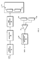
- the transmitter preferably includes the signal generator 16 and a direct-sequence spread spectrum modulator 29.
- the modulator modulates the signals produced by the signal generator in accordance with a pseudorandom code, and supplies the modulated signal through a tank resonator 50 to the electrodes 18 and 20.
- the tank resonator 50 converts square waves to sine waves at the frequency of interest, without radiating energy at the higher-frequency components of the square wave.
- the receiver 22 includes the amplifier 47, which amplifies a signal that corresponds to the displacement current that passes from the user to the inner electrode 24, though a synchronous detector 52 to the outer electrode 26.
- a synchronous detector 52 operating in a conventional manner, demodulates the signal and reproduces the transmitted information.
- each transmitter 14 uses a different pseudorandom code in its modulator 29. This allows the receiver to distinguish the signals transmitted simultaneously by various transmitters, based on the codes. Alternatively, the transmitters may transmit at different carrier frequencies or at different times, in which case the receiver distinguishes between the various signals based on these frequencies or times of transmission.
- Fig. 4 depicts one application for the system.
- the system is incorporated into various components of a paging system that the user wears or carries.
- the user carries, for example, in his pocket, a paging terminal 60 that receives paging messages over the air in a conventional manner.
- the paging terminal includes the transmitter 14, which is capacitively coupled to the user and to ground.
- the transmitter produces signals that include information from the received messages and passes the signals to the user as displacement currents.
- a display device 62 that is incorporated in, for example, the user's watch 64, includes a receiver 22 that is capacitively coupled to the user.
- the receiver 22 reproduces the signals from the displacement current passed to it, and the display then presents the information included therein to the user.
- the watch 64 may also include one or more buttons (not shown) that a user may use to select, for example, storage options for the paging messages.
- the various system components may instead be incorporated into the user's glasses 66, shoes 68, belt buckle 70, and so forth.
- Another application for the wireless system is to pass information that represents the user's physiological condition between a plurality of transmitters and a receiver that are each capacitively coupled to the user.
- a plurality of transmitters 14 1 ,14 2 ,14 3 ... are connected, respectively, to instruments 74 1 ,74 2 ,74 3 ... that measure blood pressure, take EKG readings, and so forth.
- Each transmitter receives data from the associated instrument and produces modulated signals that include the data. These signals result in displacement currents passing between the transmitters and the user 10 and from the user 10 to the receiver 22, which is connected to a recorder 76 that records the data.
- the system may also be used to pass signals inter-body to a receiver that is proximate to but not mounted or carried on the user's body.
- the return path for the current is through room ground, and no connecting wires are required.
- a user wears the transmitter 14, for example, as part of his watch 64, and the receiver 22 is mounted on a door (not shown) or within a doorknob 80 that controls the opening of the door.
- the transmitter 14 produces a modulated signal that includes a personal identification number. This signal is capacitively coupled to the receiver 22 when the user grasps or comes sufficiently close to the doorknob.
- the receiver 22 determines if it recognizes the number, and if so locks or unlocks the door, as appropriate.
- two users shaking hands can each exchange information between receivers and transmitters that they are carrying, to exchange, for example, electronic business cards.
- an array 102 of receivers 22 is at a fixed location.
- the receivers 22 determine the relative position of a user-carried transmitter from the relative strengths of the received signals.
- Fig. 7 depicts the wireless system incorporated into a personal computer 100.
- the system provides to the user a multi-dimensional input device that allows a user, with hand gestures, to move in two dimensions an on-screen object such as a cursor, or in three dimensions a three-dimensional on-screen object or herself, that is, her viewpoint, through a virtual space that is displayed on the screen.
- the system includes the array 102 of receivers 22, which are mounted in close proximity to a screen 104 of a monitor 106.
- the transmitter 14 is incorporated into a foot pedal 108 that the user contacts when she desires to move an on-screen object or, her virtual space viewpoint.
- the user places her foot 110 on the foot pedal 108 and moves one of her hands 112 in front of the screen 104.
- the transmitter 14 is capacitively coupled to the user 10 and to ground.
- the signals produced by the transmitter 14 are passed as currents through the user and from the user's hand 112 to the array 102 of receivers 22.
- a processor (not shown) connected to receive signals from the array 102 determines the relative position of one or both of the user's hands, based on the relative strengths of the signals received by the various receivers.
- the processor then moves, for example, the on-screen object to a corresponding location on the screen.
- the system determines where the user's hand is relative to a predetermined "neutral" position that corresponds to a mid-point in the range of movement to which the receiver responds. If, for example, the receiver responds to movements of the user's hand when the hand is at most one meter from the screen and ten centimeters to the left, right, above or below the screen, the neutral position is the center of the screen at the distance between the screen and one meter that corresponds to the middle of the operational range of the receivers.
- the system moves the user forward through the virtual space. If the user also moves one of her hands to the left of the neutral position, the system moves the user at a corresponding angle to the left in the space, and so forth. As the user moves one or both of her hands farther and farther from the neutral position, the system moves the user faster and faster through the virtual space in the direction that corresponds to the relative position of the user's hand.
- the transmitter 14 is included on the keyboard 116 or in a chair cushion 114, instead of in the foot pedal 108.
- the foot pedal may optionally be used to control the "granularity" of the user's movement in the virtual space, that is, to control the scale of the movements through the space.
- the user depresses the foot pedal to speed the user's overall movement in the virtual space and released to slow that movement. If, for example, the user is moving between buildings in the virtual space she depresses the foot pedal to accelerate her progress through the space and re-positions her hand to regulate and direct the accelerated movements.
- she releases the foot pedal to slow her movements, and again uses her hand to regulate and direct the decelerated movements.
- the wireless system readily translates the three-dimensional movements of a user's hand to movements of the user through three-dimensional virtual space. This is in contrast to input devices that operate in two-dimensions and cannot readily convey simultaneously backward or forward, up or down, and left or right movements to the on-screen objects. Further, the user may direct the movement using one or both of her hands, as appropriate.
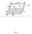
- a laptop computer 120 incorporates the wireless system to replace the mouse and/or control the movement of the user through three-dimensional virtual space.
- the array 102 of receivers 22 is mounted adjacent to the screen 104 in the lid 121 of the laptop.
- the transmitter 14 is incorporated into the base 122 of the laptop, on one side of or next to the keyboard 116.
- a user touches the transmitter 14 with one hand, for example, her left hand, and controls the movements of objects displayed on the screen by positioning her right hand in front of the screen, as discussed above with reference to Fig. 7
- One or more auxiliary receivers 22a may be mounted on the keyboard 116, to allow a user to select, or "click on,” a particular on-screen object. The user makes her selection by moving the thumb of her left hand proximate to the appropriate auxiliary receiver 22a.
- Fig. 9 depicts a portable, scalable input device 200 that consists of an array 201 of receivers 22.
- the array includes three orthogonal, electrically isolated electrodes 202-204 that are part of three receivers 22. Each electrode is capacitively coupled, through the air and through room ground, to a user (not shown) who is nearby.
- a processor (not shown) connected to process the signals received by the electrodes determines the relative position of the user based on the strengths of the signals received by each of the electrodes.
- This array may be used instead of the array 102 depicted in Figs. 7 and 8.
- the electrodes 202-204 can be extended or collapsed over a range of several inches to two feet, as necessary, to scale the expected range of movement of the user or users to the range of movements of on-screen objects in, for example, three-dimensional virtual space.
- the electrodes can be selectively extended and collapsed to accommodate fully the expected range of movement.
- the device 200 when collapsed fits into a pocket for easy transport.
- Fig. 10 illustrates an alternative wireless system that includes multiple receivers 22 that are connected to lines 204.
- the lines are arranged in a grid 206 and may be included in a rug or floor.
- a user carries a transmitter 14, preferable in his or her shoes.
- the wireless system determines the position of the user by determining which receivers receive the strongest signals from the transmitter. The receivers distinguish individual users based on the modulation codes associated with their respective transmitters. Again, the return path for current is through room ground, and thus, the transmitter and receiver electrodes pass the signals capacitively instead of as radiated energy.
Claims (17)
- Drahtloses Kommunikationssystem, umfassend:A einen oder mehrere Sender (14) zum Erzeugen von niederfrequenten Signalen, die Daten umfassen, wobei die Sender (14) jeweils dafür ausgelegt sind, um kapazitiv mit einem ansprechenden Benutzer (10) und mit Masse gekoppelt zu sein, wobei jeder Sender (14) betriebsfähig ist, um an den ansprechenden Benutzer (10) einen Strom zu führen, der zu den niederfrequenten Signalen gehört; undB einen oder mehrere Empfänger (22), wobei jeder Empfänger (22) von einem zugehörigen einen der Benutzer (10) versetzt und mit Masse gekoppelt ist, um dann, wenn kapazitiv mit dem zugehörigen Benutzer (10) gekoppelt, einen oder mehrere Ströme zu empfangen, die zu den Signalen gehören, die von den Sendern (14) erzeugt werden, wobei die Empfänger (22) betriebsfähig sind, um die gesendeten Signale zu reproduzieren und die Daten wiederherzustellen.
- Drahtloses Kommunikationssystem nach Anspruch 1, wobei der Sender (14) umfasst:i ein Paar von Elektroden (18, 20); undii einen Signalgenerator (16), der zwischen die Elektroden (18, 20) geschaltet ist, wobei der Signalgenerator (16) betriebsfähig ist, um die niederfrequenten Signale zu erzeugen, die zu einem zugehörigen Verschiebestrom zwischen den Elektroden (18, 20) und dem Benutzer (10) führen.
- Drahtloses Kommunikationssystem nach Anspruch 1 oder 2, wobei das System ferner umfasst:einen Prozessor, um aus den Signalen, die von den Empfängern (22) reproduziert werden, die Position der Benutzer (10) relativ zu einem oder mehreren der Empfänger (22) zu bestimmen.
- Drahtloses Kommunikationssystem nach Anspruch 3, wobei die Empfänger (22) benachbart oder in nächster Nähe zu einem Computerschirm (104) angebracht sind; und
der Prozessor betriebsfähig ist, um einen Cursor an eine Position auf dem Schirm (104) zu bewegen, die zu der Position des Benutzers (10) relativ zu einem oder mehreren der Empfänger (22) gehört. - Drahtloses Kommunikationssystem nach Anspruch 1, wobei das System ferner eine Vielzahl von Sendern (14) umfasst, wobei zu jedem der Sender (14) ein vorgegebener Code gehört, der sich von den Codes, die zu den anderen Sendern (14) in dem System gehören, unterscheidet, wobei der Empfänger (22) betriebsfähig ist, um die Codes zu verwenden, um zwischen den Signalen, die von jedem der Sender (14) in der Vielzahl von Sendern (14) geführt werden, zu unterscheiden.
- Drahtloses Kommunikationssystem nach Anspruch 5, wobei jeder der Sender (14) in der Vielzahl von Sendern (14) dafür ausgelegt ist, um kapazitiv mit einem anderen Benutzer gekoppelt zu sein, und der Empfänger (22) betriebsfähig ist, um Signale jeweils von den einzelnen Sendern (14) zu empfangen, wenn der Empfänger (22) kapazitiv mit den einzelnen Sendern (14) gekoppelt ist.
- Drahtloses Kommunikationssystem nach Anspruch 3, wobei die Empfänger (22) benachbart oder in nächster Nähe zu einem Computerschirm (104) angebracht sind; und der Prozessor betriebsfähig ist, um ein oder mehrere Objekte an Position auf dem Schirm (104) zu bewegen, die zu den Positionen von einem oder mehreren der Benutzer (10) relativ zu einem oder mehreren der Empfänger (22) gehören.
- Drahtloses Kommunikationssystem nach Anspruch 3, wobei:i die Sender (14) jeweils dafür ausgelegt sind, um Signale zu senden, zu denen ein unterschiedlicher vorgegebener Code gehört; undii die Empfänger (22) dafür ausgelegt sind, um zwischen den Signalen, die von den einzelnen Sender (14) erzeugt werden, auf Grundlage der Codes zu unterscheiden.
- Drahtloses Kommunikationssystem nach Anspruch 3, wobei die Empfänger (22) zwischen den Signalen, die von den einzelnen Sendern (14) erzeugt werden, auf Grundlage der Zeiten, zu denen die Signale gesendet werden, unterscheiden.
- Drahtloses Kommunikationssystem nach Anspruch 3, wobei:i die Sender (14) jeweils dafür ausgelegt sind, um Signale bei unterschiedlichen vorgegebenen Frequenzen zu senden; undii die Empfänger (22) dafür ausgelegt sind, um zwischen den Signalen, die von den einzelnen Sendern (14) erzeugt werden, auf Grundlage der Frequenzen zu unterscheiden.
- Computersystem, umfassend:A einen Schirm (104) zum Anzeigen von einem oder mehreren On-Screen-Objekten;B eine Tastatur (116) für eine Dateneingabe in das System;C einen Sender (14) zum Erzeugen von niederfrequenten Signalen, wobei der Sender (14) dafür ausgelegt ist, um kapazitiv mit einem Benutzer (10) gekoppelt zu sein, um an den Benutzer (10) einen Strom zu führen, zu dem die Niederfrequenzsignale gehören;D einen oder mehrere Empfänger (22), die benachbart oder in nächster Nähe zu dem Schirm (104) angebracht sind, wobei jeder der Empfänger (22) in der Vielzahl betriebsfähig ist, um von dem Benutzer (10), durch eine kapazitive Kopplung mit dem Benutzer (10), einen Strom zu empfangen, der zu den Signalen gehört, die von dem Sender (14) erzeugt werden, und um die Position der nächsten Extremität des Körpers des Benutzers (10) relativ zu einem oder mehreren der Empfänger (22) zu bestimmen; undE einen Prozessor zum Steuern der Schirm-(104)-Anzeige, wobei der Prozessor den Schirm (104) anweist, ein oder mehrere der Objekte an Positionen anzuzeigen, die der Position der Extremität des Benutzers (10) entsprechen, wie von einem oder mehreren der Empfänger (22) bestimmt.
- System nach Anspruch 11, wobei:wobei das System ferner einen Wählempfänger (22a) umfasst, der auf dem System angebracht ist, um auf Grundlage der Stärke der empfangenen Signale zu bestimmen, ob der Benutzer (10) gerade die Information wählt, die unter dem Cursor angezeigt wird, wobei das System bestimmt, dass der Benutzer (10) die Information wählt, wenn die Stärke der Signale, die von dem Wählempfänger (22a) empfangen werden, über einer vorgegebenen Schwelle ist.A das eine oder die mehreren On-Screen-Objekte einen Cursor umfassen;
- System nach Anspruch 12, wobei der Wählempfänger (22) auf der Tastatur (116) angebracht ist.
- System nach Anspruch 13, wobei das System ferner eine Vielzahl von Wählempfängern (22a) umfasst.
- Drahtloses Kommunikationssystem nach Anspruch 1, wobei der Empfänger (22) auf einem Objekt angebracht ist.
- Drahtloses Kommunikationssystem nach Anspruch 1, wobei der Empfänger (22) dafür ausgelegt ist, um mit einem anderen Benutzer gekoppelt zu sein.
- Drahtloses Kommunikationssystem nach Anspruch 1, wobei:i. der Sender (14) auch dafür ausgelegt ist, Signale zu empfangen; undii. der Empfänger (22) auch dafür ausgelegt ist, Signale zu senden.
Applications Claiming Priority (3)
| Application Number | Priority Date | Filing Date | Title |
|---|---|---|---|
| US43698295A | 1995-05-08 | 1995-05-08 | |
| US436982 | 1995-05-08 | ||
| PCT/US1996/006077 WO1996036134A1 (en) | 1995-05-08 | 1996-05-01 | System for non-contact sensing and signalling using human body as signal transmission medium |
Publications (2)
| Publication Number | Publication Date |
|---|---|
| EP0824799A1 EP0824799A1 (de) | 1998-02-25 |
| EP0824799B1 true EP0824799B1 (de) | 2002-08-21 |
Family
ID=23734590
Family Applications (1)
| Application Number | Title | Priority Date | Filing Date |
|---|---|---|---|
| EP96913886A Expired - Lifetime EP0824799B1 (de) | 1995-05-08 | 1996-05-01 | System zum kontaktlosen abtasten und signalisierung mit menschlichem körper als signalübertragungsmedium |
Country Status (10)
| Country | Link |
|---|---|
| US (1) | US5914701A (de) |
| EP (1) | EP0824799B1 (de) |
| JP (1) | JP4074661B2 (de) |
| KR (1) | KR100395863B1 (de) |
| AU (1) | AU5671396A (de) |
| BR (1) | BR9608465A (de) |
| CA (1) | CA2220294C (de) |
| DE (1) | DE69623115T2 (de) |
| ES (1) | ES2180767T3 (de) |
| WO (1) | WO1996036134A1 (de) |
Cited By (2)
| Publication number | Priority date | Publication date | Assignee | Title |
|---|---|---|---|---|
| WO2013188895A2 (de) | 2012-06-22 | 2013-12-27 | Mkw Electronics Gmbh | Verfahren zur aufzeichnung von daten |
| US8866760B2 (en) | 2008-12-05 | 2014-10-21 | Koninklijke Philips N.V. | User identification based on body-coupled communication |
Families Citing this family (347)
| Publication number | Priority date | Publication date | Assignee | Title |
|---|---|---|---|---|
| US5914610A (en) * | 1994-02-03 | 1999-06-22 | Massachusetts Institute Of Technology | Apparatus and method for characterizing movement of a mass within a defined space |
| US6650870B2 (en) | 1995-12-15 | 2003-11-18 | Innovision Research & Technology Plc | Data communication apparatus |
| US5948031A (en) * | 1996-02-23 | 1999-09-07 | Nec Technologies, Inc. | Vehicle passenger sensing system and method |
| US6161070A (en) * | 1996-02-23 | 2000-12-12 | Nec Home Electronics, Inc. | Passenger detection system |
| US8350804B1 (en) * | 1996-04-10 | 2013-01-08 | Moll Edward W | Thought controlled system |
| US6223018B1 (en) * | 1996-12-12 | 2001-04-24 | Nippon Telegraph And Telephone Corporation | Intra-body information transfer device |
| US6747632B2 (en) * | 1997-03-06 | 2004-06-08 | Harmonic Research, Inc. | Wireless control device |
| US6211799B1 (en) * | 1997-11-06 | 2001-04-03 | Massachusetts Institute Of Technology | Method and apparatus for transbody transmission of power and information |
| US6104913A (en) * | 1998-03-11 | 2000-08-15 | Bell Atlantic Network Services, Inc. | Personal area network for personal telephone services |
| IL138839A0 (en) * | 1998-04-06 | 2001-10-31 | Sterling Hans Rudolf | Positioning a cursor on the display screen of a computer |
| US6282407B1 (en) * | 1998-04-16 | 2001-08-28 | Motorola, Inc. | Active electrostatic transceiver and communicating system |
| US6879809B1 (en) | 1998-04-16 | 2005-04-12 | Motorola, Inc. | Wireless electrostatic charging and communicating system |
| US6275681B1 (en) * | 1998-04-16 | 2001-08-14 | Motorola, Inc. | Wireless electrostatic charging and communicating system |
| WO2000015931A1 (de) | 1998-09-14 | 2000-03-23 | Koninklijke Philips Electronics N.V. | Elektronisches kommunikationssystem |
| US6580356B1 (en) * | 1998-11-05 | 2003-06-17 | Eckhard Alt | Advanced personal identification systems and techniques |
| GB2344257A (en) | 1998-11-26 | 2000-05-31 | Innovision Research And Techno | Data communication apparatus and board game |
| US6336031B1 (en) | 1998-12-22 | 2002-01-01 | Nortel Networks Limited | Wireless data transmission over quasi-static electric potential fields |
| US6281888B1 (en) * | 1999-01-07 | 2001-08-28 | International Business Machines Corporation | Pen input device using electrostatic coupling |
| US6542717B1 (en) * | 1999-01-20 | 2003-04-01 | International Business Machines Corporation | System and method for optimizing personal area network (PAN) electrostatic communication |
| US6561978B1 (en) | 1999-02-12 | 2003-05-13 | Cygnus, Inc. | Devices and methods for frequent measurement of an analyte present in a biological system |
| US6611250B1 (en) | 1999-06-21 | 2003-08-26 | Peter M. Prince | Foot pedal computer mouse including modular auxiliary unit |
| US7362973B1 (en) | 1999-09-15 | 2008-04-22 | International Business Machines Corporation | Protecting secret data entry from infrared and audio eavesdropping |
| JP2001195368A (ja) | 1999-11-01 | 2001-07-19 | Sony Corp | 認証情報通信システムおよび認証情報通信方法、携帯情報処理装置、並びにプログラム提供媒体 |
| JP2001144662A (ja) * | 1999-11-11 | 2001-05-25 | Sony Corp | 携帯型オーディオ・リスニング装置 |
| JP2001144661A (ja) | 1999-11-17 | 2001-05-25 | Sony Corp | データ送信装置およびデータ受信装置 |
| JP2001156724A (ja) * | 1999-11-30 | 2001-06-08 | Matsushita Electric Works Ltd | データ通信システム |
| JP2001160801A (ja) * | 1999-12-02 | 2001-06-12 | Sony Corp | 二重方式デジタルデータ伝送方法および装置 |
| US6695207B1 (en) * | 2000-02-04 | 2004-02-24 | Carroll Boyd Norris, Jr. | System for secure, identity authenticated, and immediate financial transactions as well as activation of varied instrumentalities |
| JP3898418B2 (ja) * | 2000-04-13 | 2007-03-28 | 株式会社エヌ・ティ・ティ・ドコモ | 通信システム |
| US7206423B1 (en) * | 2000-05-10 | 2007-04-17 | Board Of Trustees Of University Of Illinois | Intrabody communication for a hearing aid |
| EP1168678B1 (de) | 2000-06-27 | 2003-09-03 | Matsushita Electric Works, Ltd. | Datenübertragungssystem unter Verwendung eines menschlichen Körpers als Signalübertragungsweg |
| WO2002015560A2 (en) * | 2000-08-12 | 2002-02-21 | Georgia Tech Research Corporation | A system and method for capturing an image |
| US6633772B2 (en) | 2000-08-18 | 2003-10-14 | Cygnus, Inc. | Formulation and manipulation of databases of analyte and associated values |
| US20020026111A1 (en) * | 2000-08-28 | 2002-02-28 | Neil Ackerman | Methods of monitoring glucose levels in a subject and uses thereof |
| DE60102331T2 (de) | 2000-09-08 | 2005-03-17 | Matsushita Electric Works, Ltd., Kadoma | Datenübertragungssystem unter Verwendung eines menschlichen Körpers als Signalübertragungsweg |
| JP3507028B2 (ja) * | 2000-11-14 | 2004-03-15 | 日本電信電話株式会社 | データ通信システムおよび生体接触部 |
| JP2002244781A (ja) * | 2001-02-15 | 2002-08-30 | Wacom Co Ltd | 入力システム、プログラム、及び、記録媒体 |
| JP2002244794A (ja) * | 2001-02-19 | 2002-08-30 | Sony Corp | 情報入力装置 |
| US20020136264A1 (en) * | 2001-03-20 | 2002-09-26 | Herleikson Earl C. | Spread spectrum measurement device |
| DE10119283A1 (de) * | 2001-04-20 | 2002-10-24 | Philips Corp Intellectual Pty | System zur drahtlosen Übertragung elektrischer Leistung, ein Kleidungsstück, ein System von Kleidungsstücken und Verfahren zum Übertragen von Signalen und/oder elektrischer Leistung |
| US6777922B2 (en) * | 2001-05-14 | 2004-08-17 | Sony Corporation | Information processing apparatus for inputting a signal, and method therefor |
| JP4019742B2 (ja) * | 2001-05-14 | 2007-12-12 | ソニー株式会社 | 情報伝送装置及び情報伝送システム |
| WO2003005293A2 (en) * | 2001-06-29 | 2003-01-16 | Hans Rudolf Sterling | Apparatus for sensing the position of a pointing object |
| US20030030542A1 (en) * | 2001-08-10 | 2003-02-13 | Von Hoffmann Gerard | PDA security system |
| FR2834813B1 (fr) * | 2002-01-16 | 2006-07-14 | Simu | Dispositif securise de programmation et de controle de l'ouverture d'un moyen de protection d'une zone ou d'un batiment protege |
| DE10206128B4 (de) * | 2002-02-14 | 2010-10-21 | Ident Technology Ag | Elektrisches Handwerkzeug |
| US7352996B2 (en) * | 2002-03-29 | 2008-04-01 | Ncr Corporation | System and method for coupling users to a retail computer system with low risk of eavesdropping |
| DE10232934A1 (de) * | 2002-07-19 | 2004-01-29 | Ident Technology Ag | Handgriffeinrichtung sowie Sicherheitsschaltungsanordnung insbesondere für ein kraftbetriebenes Werkzeug |
| US6954867B2 (en) * | 2002-07-26 | 2005-10-11 | Microsoft Corporation | Capacitive sensing employing a repeatable offset charge |
| US7027836B2 (en) * | 2002-09-10 | 2006-04-11 | Eastman Kodak Company | Method and system for establishing a communication network |
| US7009488B2 (en) * | 2002-09-25 | 2006-03-07 | Hrl Laboratories, Llc | Selective equipment lockout |
| JP3773887B2 (ja) * | 2002-09-30 | 2006-05-10 | 日本電信電話株式会社 | トランシーバ |
| JP3935041B2 (ja) * | 2002-10-10 | 2007-06-20 | 日本電信電話株式会社 | 情報送受信システム |
| WO2004053823A1 (en) * | 2002-12-09 | 2004-06-24 | Adam Kaplan | Method and apparatus for user interface |
| US7512448B2 (en) * | 2003-01-10 | 2009-03-31 | Phonak Ag | Electrode placement for wireless intrabody communication between components of a hearing system |
| KR100873683B1 (ko) * | 2003-01-25 | 2008-12-12 | 한국과학기술연구원 | 인체통신방법, 인체통신시스템 및 이에 사용되는 캡슐형 내시경 |
| KR100522132B1 (ko) * | 2003-01-25 | 2005-10-18 | 한국과학기술연구원 | 인체통신시스템에서의 데이터 수신방법 및 수신장치 |
| US8155586B2 (en) * | 2003-01-25 | 2012-04-10 | Korea Institute Of Science And Technology | Method and system for data communication using a body |
| RU2302699C2 (ru) * | 2003-02-27 | 2007-07-10 | Сони Корпорейшн | Система связи |
| JP4114143B2 (ja) * | 2003-02-27 | 2008-07-09 | ソニー株式会社 | 通信システム、通信方法及び通信装置 |
| JP4088896B2 (ja) * | 2003-02-27 | 2008-05-21 | ソニー株式会社 | 通信システム及び通信装置 |
| JP4158097B2 (ja) * | 2003-02-27 | 2008-10-01 | ソニー株式会社 | 認証システム |
| EP1457863A3 (de) * | 2003-03-11 | 2007-02-21 | Fraunhofer-Gesellschaft zur Förderung der angewandten Forschung e.V. | Handzeichen basierende Eingabevorrichtung für eine Benutzerschnittstelle eines Rechners |
| US7312788B2 (en) * | 2003-03-11 | 2007-12-25 | Fraunhofer-Gesellschaft Zur Foerderung Der Angewandten Forschung E.V. | Gesture-based input device for a user interface of a computer |
| EP2284743A3 (de) * | 2003-03-28 | 2013-08-14 | CareFusion 303, Inc. | Infusionsdatenkommunikationssystem |
| JP4507058B2 (ja) | 2003-06-05 | 2010-07-21 | ソニー株式会社 | 距離検出システム |
| JP4378607B2 (ja) * | 2003-08-29 | 2009-12-09 | ソニー株式会社 | 測定装置 |
| EP1587226B1 (de) * | 2003-12-05 | 2007-10-24 | Nippon Telegraph and Telephone Corporation | Reaktanzeinstelleinrichtung, übertragungsverfahren und übertragungseinrichtung damit, dafür geeignete signalverarbeitungsschaltung,reaktanzeinstellverfahren, übertragungsverfahren und empfangsverfahren |
| WO2005062236A2 (en) * | 2003-12-18 | 2005-07-07 | Axalto Sa | A system for identifying an individual in an electronic transaction |
| US7392091B2 (en) * | 2003-12-30 | 2008-06-24 | Cochlear Limited | Implanted antenna and radio communications link |
| US20100016929A1 (en) * | 2004-01-22 | 2010-01-21 | Arthur Prochazka | Method and system for controlled nerve ablation |
| JP4879754B2 (ja) | 2004-01-22 | 2012-02-22 | リハブトロニクス インコーポレーテッド | 移植された非活性導電体を介して、身体組織に電流を搬送する方法 |
| JP2005227874A (ja) | 2004-02-10 | 2005-08-25 | Sony Corp | 情報処理システム、情報処理装置および情報処理方法、プログラム、並びに記録媒体 |
| WO2005088859A1 (de) * | 2004-03-15 | 2005-09-22 | Siemens Ag Österreich | Nahbereichdatenübertrangung mit geringeren datenraten unter verwendung eines gee igneten elektrischen streufeldes |
| US7208694B2 (en) | 2004-04-16 | 2007-04-24 | Wabtec Holding Corp. | Capacitance activated switch device |
| US20080045843A1 (en) * | 2004-08-12 | 2008-02-21 | Tomoharu Tsuji | Via-Human-Body Information Transmission System and Transmitter-Receiver |
| KR100654319B1 (ko) * | 2004-09-01 | 2006-12-08 | 한국전자통신연구원 | 근역장을 이용한 통신 시스템 및 그 방법 |
| JP3926357B2 (ja) * | 2004-09-28 | 2007-06-06 | 秀雄 保田 | データ送受信機及びデータ送受信システム |
| DE102005015802A1 (de) * | 2005-04-06 | 2006-10-12 | Ident Technology Ag | Verfahren zur Datenübertragung über den Körper |
| KR100671234B1 (ko) * | 2004-10-07 | 2007-01-18 | 한국전자통신연구원 | 전송매체를 이용한 통신장치 및 그 방법 |
| JP4665904B2 (ja) * | 2004-11-30 | 2011-04-06 | コニカミノルタホールディングス株式会社 | 情報処理装置 |
| US7978063B2 (en) * | 2004-12-13 | 2011-07-12 | Koninklijke Philips Electronics N.V. | Wireless network having body coupled communication for mobile patient monitoring |
| US8253693B2 (en) * | 2005-02-17 | 2012-08-28 | Koninklijke Philips Electronics N.V. | Device capable of being operated within a network, network system, method of operating a device within a network, program element, and computer-readable medium |
| JP2006268614A (ja) | 2005-03-25 | 2006-10-05 | Sony Corp | 情報処理システム、情報処理装置および方法、プログラム、並びに記録媒体 |
| JP4403512B2 (ja) | 2005-03-29 | 2010-01-27 | ソニー株式会社 | 情報処理システム、情報処理装置および方法、プログラム、並びに記録媒体 |
| JP4586618B2 (ja) * | 2005-04-18 | 2010-11-24 | ソニー株式会社 | 人体通信システム及び通信装置 |
| US8659546B2 (en) | 2005-04-21 | 2014-02-25 | Oracle America, Inc. | Method and apparatus for transferring digital content |
| CN103259027A (zh) | 2005-04-28 | 2013-08-21 | 普罗透斯数字保健公司 | 药物信息系统 |
| US8802183B2 (en) | 2005-04-28 | 2014-08-12 | Proteus Digital Health, Inc. | Communication system with enhanced partial power source and method of manufacturing same |
| JP2006350990A (ja) | 2005-05-17 | 2006-12-28 | Sony Corp | 情報処理システム、および情報処理方法 |
| JP2006323498A (ja) * | 2005-05-17 | 2006-11-30 | Sony Corp | 管理システム、管理方法、情報処理装置、および情報処理方法 |
| JP4257611B2 (ja) * | 2005-05-17 | 2009-04-22 | ソニー株式会社 | 通信装置および方法、並びにプログラム |
| JP2006350993A (ja) | 2005-05-17 | 2006-12-28 | Sony Corp | 販売装置、販売方法、およびプログラム |
| JP4501073B2 (ja) * | 2005-05-17 | 2010-07-14 | ソニー株式会社 | 通信システム、送信装置、受信装置、並びに送受信装置 |
| CN101179985B (zh) * | 2005-05-24 | 2012-10-03 | 皇家飞利浦电子股份有限公司 | 用于现场测量的自动标识 |
| JP4524647B2 (ja) | 2005-06-14 | 2010-08-18 | ソニー株式会社 | 通信装置、通信方法、およびプログラム |
| JP2006352699A (ja) * | 2005-06-17 | 2006-12-28 | Sony Corp | 通信システム、通信装置および方法、並びにプログラム |
| JP2006352700A (ja) | 2005-06-17 | 2006-12-28 | Sony Corp | 通信システム、通信装置および方法、並びにプログラム |
| CA2608397A1 (en) | 2005-06-28 | 2007-01-04 | Bioness Development, Llc | Improvements to an implant, system and method using implanted passive conductors for routing electrical current |
| CN101032098B (zh) * | 2005-07-25 | 2011-11-23 | 索尼株式会社 | 通信装置和方法 |
| JP2007089131A (ja) | 2005-07-25 | 2007-04-05 | Sony Corp | 情報処理装置および方法、プログラム、並びに記録媒体 |
| DE102005038678A1 (de) * | 2005-08-16 | 2007-02-22 | Ident Technology Ag | Erfassungssystem, sowie diesem unterlegtes Erfassungsverfahren |
| US8547248B2 (en) * | 2005-09-01 | 2013-10-01 | Proteus Digital Health, Inc. | Implantable zero-wire communications system |
| TW200727609A (en) * | 2005-09-27 | 2007-07-16 | Kaba Ag | A method and system for the transmission of identification signals |
| US7868874B2 (en) | 2005-11-15 | 2011-01-11 | Synaptics Incorporated | Methods and systems for detecting a position-based attribute of an object using digital codes |
| KR100772525B1 (ko) * | 2005-12-08 | 2007-11-01 | 한국전자통신연구원 | 접촉 기반의 서비스 제공 방법, 장치 및 이를 이용하는시스템 |
| DE102005060778B4 (de) * | 2005-12-16 | 2008-06-26 | Ident Technology Ag | Kraftfahrzeug mit einem Absicherungssystem |
| JP4539551B2 (ja) | 2005-12-20 | 2010-09-08 | ソニー株式会社 | 情報処理システムおよび方法、情報処理装置および方法、並びにプログラム |
| JP4348637B2 (ja) * | 2006-01-16 | 2009-10-21 | ソニー株式会社 | 通信装置 |
| WO2007084807A1 (en) * | 2006-01-18 | 2007-07-26 | Koninklijke Philips Electronics, N.V. | Automatic and secure configuration of wireless medical networks |
| CN101389265B (zh) * | 2006-02-24 | 2011-01-26 | 皇家飞利浦电子股份有限公司 | 无线身体传感器网络 |
| AU2007234292B2 (en) * | 2006-04-03 | 2011-09-01 | Dormakaba Schweiz Ag | Method and system for information transmission |
| JP4210953B2 (ja) * | 2006-04-14 | 2009-01-21 | ソニー株式会社 | 電界制御装置及び検出装置 |
| EP2013955A4 (de) | 2006-04-21 | 2010-10-13 | Wabtec Holding Corp | Zweidrahtadapter |
| KR101315079B1 (ko) * | 2006-05-08 | 2013-10-08 | 코닌클리케 필립스 일렉트로닉스 엔.브이. | 제 1 디바이스에서 제 2 디바이스로의 애플리케이션 데이터전송 방법, 및 데이터 전송 시스템 |
| US7876906B2 (en) * | 2006-05-30 | 2011-01-25 | Sonitus Medical, Inc. | Methods and apparatus for processing audio signals |
| US20070281614A1 (en) * | 2006-06-01 | 2007-12-06 | Motorola, Inc. | Method and apparatus for dual mode communications |
| EP2048124A1 (de) * | 2006-06-21 | 2009-04-15 | Hitachi Metals, Limited | Magnetmaterialantenne uind ferritsinterteil |
| JP2008027219A (ja) * | 2006-07-21 | 2008-02-07 | Sony Corp | 情報処理システム、受信装置および方法、記録媒体、並びにプログラム |
| CN101495030B (zh) * | 2006-07-28 | 2012-12-12 | 皇家飞利浦电子股份有限公司 | 用分级密钥管理基础设施对监测数据的自动传送和识别 |
| JP4206110B2 (ja) * | 2006-08-11 | 2009-01-07 | 日本電信電話株式会社 | 命令信号生成方法 |
| US8291912B2 (en) * | 2006-08-22 | 2012-10-23 | Sonitus Medical, Inc. | Systems for manufacturing oral-based hearing aid appliances |
| US8172762B2 (en) * | 2006-09-01 | 2012-05-08 | Proteus Biomedical, Inc. | Simultaneous blood flow and hematocrit sensor |
| CA2663017C (en) * | 2006-09-08 | 2014-03-25 | Sonitus Medical, Inc. | Methods and apparatus for treating tinnitus |
| KR100809274B1 (ko) | 2006-09-20 | 2008-03-03 | 삼성전기주식회사 | 신체를 이용한 안테나 |
| KR100767414B1 (ko) * | 2006-09-21 | 2007-10-17 | 한국과학기술원 | 인체를 이용하는 무선 영상 송수신 장치 |
| KR100770010B1 (ko) * | 2006-09-29 | 2007-10-25 | 한국전자통신연구원 | 고속 데이터 전송을 위한 인체통신 시스템 |
| US8483820B2 (en) * | 2006-10-05 | 2013-07-09 | Bioness Inc. | System and method for percutaneous delivery of electrical stimulation to a target body tissue |
| SG175681A1 (en) | 2006-10-25 | 2011-11-28 | Proteus Biomedical Inc | Controlled activation ingestible identifier |
| US7777719B2 (en) * | 2007-01-19 | 2010-08-17 | Nokia Corporation | System using a living body as a transmission medium |
| KR100981543B1 (ko) * | 2007-01-23 | 2010-09-10 | 삼성전자주식회사 | 휴대 디스플레이 장치의 백라이트 제어 방법 및 장치 |
| CN101686800A (zh) | 2007-02-01 | 2010-03-31 | 普罗秋斯生物医学公司 | 可摄入事件标记器系统 |
| WO2008097037A1 (en) | 2007-02-07 | 2008-08-14 | Samsung Electronics Co., Ltd. | Method and apparatus for multiplexing frequency hopping in a communication system |
| WO2008098399A1 (de) * | 2007-02-14 | 2008-08-21 | Kaba Ag | System und portables gerät für die übertragung von identifikationssignalen |
| CA2676280C (en) | 2007-02-14 | 2018-05-22 | Proteus Biomedical, Inc. | In-body power source having high surface area electrode |
| EP2113111B1 (de) * | 2007-02-15 | 2017-11-22 | Koninklijke Philips N.V. | Residente kommentierungen für einen drahtlosen sensor |
| EP2428629B1 (de) | 2007-03-05 | 2018-11-28 | dormakaba Schweiz AG | Verwendung eines zugangskontrollsystems sowie gebäude mit einem system für die zugangskontrolle |
| US20080229914A1 (en) * | 2007-03-19 | 2008-09-25 | Trevor Nathanial | Foot operated transport controller for digital audio workstations |
| EP2146449A1 (de) | 2007-03-30 | 2010-01-20 | Alps Electric Co., Ltd. | Datenkommunikationssystem |
| KR20090128567A (ko) | 2007-04-20 | 2009-12-15 | 알프스 덴키 가부시키가이샤 | 통신기기, 수신기 및 송신기 |
| US8115618B2 (en) | 2007-05-24 | 2012-02-14 | Proteus Biomedical, Inc. | RFID antenna for in-body device |
| US8270638B2 (en) | 2007-05-29 | 2012-09-18 | Sonitus Medical, Inc. | Systems and methods to provide communication, positioning and monitoring of user status |
| US20080304677A1 (en) * | 2007-06-08 | 2008-12-11 | Sonitus Medical Inc. | System and method for noise cancellation with motion tracking capability |
| US20090028352A1 (en) * | 2007-07-24 | 2009-01-29 | Petroff Michael L | Signal process for the derivation of improved dtm dynamic tinnitus mitigation sound |
| US20120235632A9 (en) * | 2007-08-20 | 2012-09-20 | Sonitus Medical, Inc. | Intra-oral charging systems and methods |
| US8433080B2 (en) * | 2007-08-22 | 2013-04-30 | Sonitus Medical, Inc. | Bone conduction hearing device with open-ear microphone |
| US8224013B2 (en) | 2007-08-27 | 2012-07-17 | Sonitus Medical, Inc. | Headset systems and methods |
| WO2009030255A1 (de) | 2007-09-04 | 2009-03-12 | Bartec Gmbh | Annäherungswarnsystem zum nachweis einer annäherung einer person an ein objekt, insbesondere an eine maschine |
| US7682303B2 (en) | 2007-10-02 | 2010-03-23 | Sonitus Medical, Inc. | Methods and apparatus for transmitting vibrations |
| EP2207471B1 (de) * | 2007-10-03 | 2018-04-11 | University of Utah Research Foundation | Drahtlose biomedizinische miniatur-telemetrievorrichtung |
| JP4653241B2 (ja) * | 2007-10-11 | 2011-03-16 | アルプス電気株式会社 | 情報端末装置 |
| US8634773B2 (en) * | 2007-10-12 | 2014-01-21 | Cochlear Limited | Short range communications for body contacting devices |
| US20090105523A1 (en) * | 2007-10-18 | 2009-04-23 | Sonitus Medical, Inc. | Systems and methods for compliance monitoring |
| US8773361B2 (en) * | 2007-11-20 | 2014-07-08 | Samsung Electronics Co., Ltd. | Device identification method and apparatus, device information provision method and apparatus, and computer-readable recording mediums having recorded thereon programs for executing the device identification method and the device information provision method |
| US8917247B2 (en) | 2007-11-20 | 2014-12-23 | Samsung Electronics Co., Ltd. | External device identification method and apparatus in a device including a touch spot, and computer-readable recording mediums having recorded thereon programs for executing the external device identification method in a device including a touch spot |
| JP2009135850A (ja) * | 2007-12-03 | 2009-06-18 | Alps Electric Co Ltd | 携帯型情報信号通信システム |
| US8795172B2 (en) * | 2007-12-07 | 2014-08-05 | Sonitus Medical, Inc. | Systems and methods to provide two-way communications |
| EP2241032B1 (de) * | 2007-12-20 | 2018-02-28 | Koninklijke Philips N.V. | Kapazitive messung und übertragung |
| CN101904118B (zh) * | 2007-12-20 | 2014-07-23 | 皇家飞利浦电子股份有限公司 | 身体耦合的通信系统的电极多样性 |
| JP5684573B2 (ja) | 2007-12-20 | 2015-03-11 | コーニンクレッカ フィリップス エヌ ヴェ | 複数の結合モードの間の切り替え |
| CN101897134B (zh) | 2007-12-26 | 2013-06-26 | 阿尔卑斯电气株式会社 | 便携设备 |
| US7974845B2 (en) | 2008-02-15 | 2011-07-05 | Sonitus Medical, Inc. | Stuttering treatment methods and apparatus |
| US8270637B2 (en) | 2008-02-15 | 2012-09-18 | Sonitus Medical, Inc. | Headset systems and methods |
| US8023676B2 (en) | 2008-03-03 | 2011-09-20 | Sonitus Medical, Inc. | Systems and methods to provide communication and monitoring of user status |
| US8150075B2 (en) | 2008-03-04 | 2012-04-03 | Sonitus Medical, Inc. | Dental bone conduction hearing appliance |
| US20090226020A1 (en) | 2008-03-04 | 2009-09-10 | Sonitus Medical, Inc. | Dental bone conduction hearing appliance |
| TWI368188B (en) * | 2008-03-18 | 2012-07-11 | Univ Nat Taiwan | Intra-body biomedical communication system (ibc) and the method use of |
| US20100060424A1 (en) * | 2008-03-19 | 2010-03-11 | Checkpoint Systems, Inc. | Range Extension and Multiple Access in Modulated Backscatter Systems |
| JP4475343B2 (ja) * | 2008-04-04 | 2010-06-09 | 村田機械株式会社 | 電子メールゲートウェイ装置 |
| US20090270673A1 (en) * | 2008-04-25 | 2009-10-29 | Sonitus Medical, Inc. | Methods and systems for tinnitus treatment |
| JP5290633B2 (ja) * | 2008-06-13 | 2013-09-18 | セミコンダクター・コンポーネンツ・インダストリーズ・リミテッド・ライアビリティ・カンパニー | 通信システム及びそれに用いられる受信装置 |
| US20090326602A1 (en) * | 2008-06-27 | 2009-12-31 | Arkady Glukhovsky | Treatment of indications using electrical stimulation |
| AU2009268827B2 (en) | 2008-07-08 | 2013-10-24 | Proteus Digital Health, Inc. | Ingestible event marker data framework |
| KR100942706B1 (ko) * | 2008-08-22 | 2010-02-16 | 한국전자통신연구원 | 인체 통신을 이용한 무선 주파수 식별 시스템 |
| US20110208032A1 (en) * | 2008-09-02 | 2011-08-25 | Kiyoaki Takiguchi | Detection device, detection method, vein sensing device, scanning probe microscope, distortion detection device and metal detection device |
| JP2010109801A (ja) | 2008-10-31 | 2010-05-13 | Alps Electric Co Ltd | 通信装置 |
| TW201020856A (en) * | 2008-11-25 | 2010-06-01 | Asustek Comp Inc | Electronic device of inputting touch free and input method thereof |
| KR20100075353A (ko) * | 2008-12-24 | 2010-07-02 | 한국전자통신연구원 | 인체영역 네트워크에서 인체의 일부를 안테나로 이용하는 통신 시스템 및 방법 |
| EP2413521A4 (de) | 2009-03-26 | 2015-12-09 | Alps Electric Co Ltd | Kommunikationssystem |
| EP2413522A4 (de) | 2009-03-26 | 2015-03-25 | Alps Electric Co Ltd | Kommunikationssystem |
| EP3906845A1 (de) | 2009-04-28 | 2021-11-10 | Otsuka Pharmaceutical Co., Ltd. | Hochzuverlässige einnehmbare ereignismarker |
| KR101610109B1 (ko) * | 2009-05-19 | 2016-04-11 | 삼성전자주식회사 | 전기장 통신을 이용한 입력 위치 추적 장치 |
| JP5271183B2 (ja) * | 2009-07-22 | 2013-08-21 | アルプス電気株式会社 | 通信装置及び通信方法 |
| WO2011020216A1 (zh) | 2009-08-18 | 2011-02-24 | Yang Changming | 侦测生理机能及姿势状态的物品、方法和系统 |
| US8726492B2 (en) * | 2009-09-09 | 2014-05-20 | Cochlear Limited | Insulated conductive element having a substantially continuous barrier layer formed through multiple coatings |
| US8460746B2 (en) * | 2009-09-09 | 2013-06-11 | Cochlear Limited | Method of forming insulated conductive element having a substantially continuous barrier layer formed via relative motion during deposition |
| CA2776368C (en) | 2009-10-02 | 2014-04-22 | Sonitus Medical, Inc. | Intraoral appliance for sound transmission via bone conduction |
| JP5471294B2 (ja) * | 2009-10-23 | 2014-04-16 | 株式会社デンソー | 人体通信用の通信装置 |
| EP2494719B1 (de) * | 2009-10-27 | 2019-03-13 | Safran Electronics & Defense | Anordnung von vorrichtungen zur implementierung einer datenübertragung über den menschlichen körper |
| TWI517050B (zh) | 2009-11-04 | 2016-01-11 | 普羅托斯數位健康公司 | 供應鏈管理之系統 |
| RU2533653C2 (ru) | 2009-12-18 | 2014-11-20 | Отис Элевэйтор Компани | Обнаружение людей относительно пассажирского транспортера с помощью емкостного датчика |
| JP5363968B2 (ja) * | 2009-12-22 | 2013-12-11 | アルプス電気株式会社 | 電界通信機能付き生体情報測定装置および生体情報測定ユニット |
| SG184494A1 (en) | 2010-04-07 | 2012-11-29 | Proteus Biomedical Inc | Miniature ingestible device |
| TWI557672B (zh) | 2010-05-19 | 2016-11-11 | 波提亞斯數位康健公司 | 用於從製造商跟蹤藥物直到患者之電腦系統及電腦實施之方法、用於確認將藥物給予患者的設備及方法、患者介面裝置 |
| JP2014504902A (ja) | 2010-11-22 | 2014-02-27 | プロテウス デジタル ヘルス, インコーポレイテッド | 医薬品を有する摂取可能なデバイス |
| KR101330262B1 (ko) * | 2010-12-14 | 2013-11-15 | 주식회사 팬택 | 데이터 변환이 가능한 인체 통신 단말 장치 및 방법 |
| US9244545B2 (en) * | 2010-12-17 | 2016-01-26 | Microsoft Technology Licensing, Llc | Touch and stylus discrimination and rejection for contact sensitive computing devices |
| US8994646B2 (en) | 2010-12-17 | 2015-03-31 | Microsoft Corporation | Detecting gestures involving intentional movement of a computing device |
| US8982045B2 (en) | 2010-12-17 | 2015-03-17 | Microsoft Corporation | Using movement of a computing device to enhance interpretation of input events produced when interacting with the computing device |
| US8988398B2 (en) | 2011-02-11 | 2015-03-24 | Microsoft Corporation | Multi-touch input device with orientation sensing |
| US9201520B2 (en) | 2011-02-11 | 2015-12-01 | Microsoft Technology Licensing, Llc | Motion and context sharing for pen-based computing inputs |
| US8616438B2 (en) | 2011-03-30 | 2013-12-31 | Hill-Rom Services, Inc. | Optical detector at point of care |
| US9077343B2 (en) | 2011-06-06 | 2015-07-07 | Microsoft Corporation | Sensing floor for locating people and devices |
| WO2015112603A1 (en) | 2014-01-21 | 2015-07-30 | Proteus Digital Health, Inc. | Masticable ingestible product and communication system therefor |
| US9756874B2 (en) | 2011-07-11 | 2017-09-12 | Proteus Digital Health, Inc. | Masticable ingestible product and communication system therefor |
| EP2734973A4 (de) | 2011-07-21 | 2015-07-01 | Proteus Digital Health Inc | Mobilkommunikationsvorrichtung, -system und -verfahren |
| US8844820B2 (en) | 2011-08-24 | 2014-09-30 | Hill-Rom Services, Inc. | Multi-directional optical reader for a patient support |
| JP6023313B2 (ja) * | 2012-05-25 | 2016-11-09 | 熊光 蔡 | 非表示信号の符号化方法及びマトリックス基板 |
| JP2014048049A (ja) * | 2012-08-29 | 2014-03-17 | Toyota Central R&D Labs Inc | 動作検出装置 |
| JP2014075670A (ja) * | 2012-10-03 | 2014-04-24 | Alps Electric Co Ltd | 情報伝達システム |
| DK2731356T3 (en) * | 2012-11-07 | 2016-05-09 | Oticon As | Body worn control device for hearing aids |
| US8982094B2 (en) | 2012-12-28 | 2015-03-17 | Shenzhen Huiding Technology Co., Ltd. | Device-to-device communications based on capacitive sensing and coupling via human body or direct device-to-device coupling |
| RU2653309C2 (ru) | 2013-01-17 | 2018-05-07 | Конинклейке Филипс Н.В. | Система и способ оказания воздействия на работу устройства системы |
| US11149123B2 (en) | 2013-01-29 | 2021-10-19 | Otsuka Pharmaceutical Co., Ltd. | Highly-swellable polymeric films and compositions comprising the same |
| EP2765720A1 (de) | 2013-02-06 | 2014-08-13 | Koninklijke Philips N.V. | Körpergekoppeltes Kommunikationssystem |
| US9830015B2 (en) * | 2013-03-15 | 2017-11-28 | Tactual Labs Co. | Orthogonal frequency scan scheme in touch system |
| US10175376B2 (en) | 2013-03-15 | 2019-01-08 | Proteus Digital Health, Inc. | Metal detector apparatus, system, and method |
| US11744481B2 (en) | 2013-03-15 | 2023-09-05 | Otsuka Pharmaceutical Co., Ltd. | System, apparatus and methods for data collection and assessing outcomes |
| FR3004563A1 (fr) * | 2013-04-15 | 2014-10-17 | Inside Secure | Procede d'acquisition d'une information biologique au moyen d'un courant intracorporel |
| RU2528085C1 (ru) * | 2013-05-23 | 2014-09-10 | Виктор Петрович Шилов | Способ внутриимпульсной модуляции-демодуляции с прямым расширением спектра |
| US9838088B2 (en) * | 2013-06-24 | 2017-12-05 | Inside Secure | Portable device including an electrode for transmitting data by intracorporeal current |
| WO2015004807A1 (ja) * | 2013-07-12 | 2015-01-15 | 株式会社 東芝 | 電子機器 |
| US9796576B2 (en) | 2013-08-30 | 2017-10-24 | Proteus Digital Health, Inc. | Container with electronically controlled interlock |
| US10084880B2 (en) | 2013-11-04 | 2018-09-25 | Proteus Digital Health, Inc. | Social media networking based on physiologic information |
| US20150127371A1 (en) * | 2013-11-06 | 2015-05-07 | Beam Technologies Inc | Connected Tracker for Oral Health Implements |
| AT515014A1 (de) * | 2013-11-07 | 2015-05-15 | Evva Sicherheitstechnologie | Verfahren und Vorrichtung zur Zutrittskontrolle |
| CN105981039B (zh) | 2013-11-22 | 2019-04-12 | 深圳市汇顶科技股份有限公司 | 安全的人体指纹传感器 |
| US10924472B2 (en) * | 2013-11-27 | 2021-02-16 | Shenzhen GOODIX Technology Co., Ltd. | Wearable communication devices for secured transaction and communication |
| US20170024542A1 (en) * | 2013-12-20 | 2017-01-26 | Koninklijke Philips N.V. | Logging system and a method of registering data for enabling monitoring of intake of a product by a user according to an intake plan |
| US10128907B2 (en) | 2014-01-09 | 2018-11-13 | Shenzhen GOODIX Technology Co., Ltd. | Fingerprint sensor module-based device-to-device communication |
| JP6781044B2 (ja) | 2014-01-10 | 2020-11-04 | カーディアック ペースメイカーズ, インコーポレイテッド | 心臓不整脈を検出するシステム |
| US20150196769A1 (en) | 2014-01-10 | 2015-07-16 | Cardiac Pacemakers, Inc. | Methods and systems for improved communication between medical devices |
| DE102014001224A1 (de) | 2014-01-16 | 2015-07-16 | Jörgen Betz | Verfahren zur personenselektiven Zutrittskontrolle |
| EP3597138B1 (de) | 2014-03-06 | 2022-11-23 | W & H Dentalwerk Bürmoos GmbH | Medizinisches, insbesondere zahnärztliches system |
| CN103888194B (zh) * | 2014-04-08 | 2016-11-02 | 深圳先进技术研究院 | 音频通信系统 |
| US10009069B2 (en) | 2014-05-05 | 2018-06-26 | Nxp B.V. | Wireless power delivery and data link |
| US9812788B2 (en) | 2014-11-24 | 2017-11-07 | Nxp B.V. | Electromagnetic field induction for inter-body and transverse body communication |
| US9819395B2 (en) * | 2014-05-05 | 2017-11-14 | Nxp B.V. | Apparatus and method for wireless body communication |
| US9819075B2 (en) | 2014-05-05 | 2017-11-14 | Nxp B.V. | Body communication antenna |
| US10014578B2 (en) | 2014-05-05 | 2018-07-03 | Nxp B.V. | Body antenna system |
| US10015604B2 (en) | 2014-05-05 | 2018-07-03 | Nxp B.V. | Electromagnetic induction field communication |
| AT515870A3 (de) | 2014-06-05 | 2022-06-15 | Smartbow Gmbh | Datennetzwerk für die Überwachung von Tieren |
| US9870083B2 (en) | 2014-06-12 | 2018-01-16 | Microsoft Technology Licensing, Llc | Multi-device multi-user sensor correlation for pen and computing device interaction |
| US9727161B2 (en) | 2014-06-12 | 2017-08-08 | Microsoft Technology Licensing, Llc | Sensor correlation for pen and touch-sensitive computing device interaction |
| CN106304848A (zh) | 2014-07-07 | 2017-01-04 | 深圳市汇顶科技股份有限公司 | 集成触摸屏和指纹传感器组件 |
| US10521041B2 (en) * | 2014-08-13 | 2019-12-31 | Texas Instruments Incorporated | Resonant line driver including energy transfer inductor for driving capacitive-load lines |
| CN107073275B (zh) | 2014-08-28 | 2020-09-01 | 心脏起搏器股份公司 | 具有触发的消隐周期的医疗设备 |
| US10255422B1 (en) | 2014-09-15 | 2019-04-09 | Apple Inc. | Identity proxy for access control systems |
| JP6551415B2 (ja) * | 2014-10-21 | 2019-07-31 | ソニー株式会社 | 送信装置及び送信方法、受信装置及び受信方法、並びに、プログラム |
| US20160143066A1 (en) * | 2014-11-19 | 2016-05-19 | Sony Corporation | Method and system for displaying web applications of a first communication device on a second communication device by using ban |
| WO2016126613A1 (en) | 2015-02-06 | 2016-08-11 | Cardiac Pacemakers, Inc. | Systems and methods for treating cardiac arrhythmias |
| WO2016126968A1 (en) | 2015-02-06 | 2016-08-11 | Cardiac Pacemakers, Inc. | Systems and methods for safe delivery of electrical stimulation therapy |
| WO2016130477A2 (en) | 2015-02-09 | 2016-08-18 | Cardiac Pacemakers, Inc. | Implantable medical device with radiopaque id tag |
| US11285326B2 (en) | 2015-03-04 | 2022-03-29 | Cardiac Pacemakers, Inc. | Systems and methods for treating cardiac arrhythmias |
| US10213610B2 (en) | 2015-03-18 | 2019-02-26 | Cardiac Pacemakers, Inc. | Communications in a medical device system with link quality assessment |
| US10050700B2 (en) | 2015-03-18 | 2018-08-14 | Cardiac Pacemakers, Inc. | Communications in a medical device system with temporal optimization |
| DE102015009199A1 (de) | 2015-07-15 | 2017-01-19 | Jörgen Betz | Personenselektives Verfahren der Zutrittskontrolle |
| US11051543B2 (en) | 2015-07-21 | 2021-07-06 | Otsuka Pharmaceutical Co. Ltd. | Alginate on adhesive bilayer laminate film |
| WO2017031221A1 (en) | 2015-08-20 | 2017-02-23 | Cardiac Pacemakers, Inc. | Systems and methods for communication between medical devices |
| EP3337559B1 (de) | 2015-08-20 | 2019-10-16 | Cardiac Pacemakers, Inc. | Systeme und verfahren zur kommunikation zwischen medizinischen vorrichtungen |
| US9819097B2 (en) | 2015-08-26 | 2017-11-14 | Nxp B.V. | Antenna system |
| US9968787B2 (en) | 2015-08-27 | 2018-05-15 | Cardiac Pacemakers, Inc. | Spatial configuration of a motion sensor in an implantable medical device |
| US9956414B2 (en) | 2015-08-27 | 2018-05-01 | Cardiac Pacemakers, Inc. | Temporal configuration of a motion sensor in an implantable medical device |
| US10159842B2 (en) | 2015-08-28 | 2018-12-25 | Cardiac Pacemakers, Inc. | System and method for detecting tamponade |
| US10226631B2 (en) | 2015-08-28 | 2019-03-12 | Cardiac Pacemakers, Inc. | Systems and methods for infarct detection |
| WO2017040153A1 (en) | 2015-08-28 | 2017-03-09 | Cardiac Pacemakers, Inc. | Systems and methods for behaviorally responsive signal detection and therapy delivery |
| WO2017044389A1 (en) | 2015-09-11 | 2017-03-16 | Cardiac Pacemakers, Inc. | Arrhythmia detection and confirmation |
| CN105125206B (zh) * | 2015-09-15 | 2019-01-22 | 中山大学 | 一种智能心电监护方法及装置 |
| EP3359251B1 (de) | 2015-10-08 | 2019-08-07 | Cardiac Pacemakers, Inc. | Anpassung der stimulationsrate bei einer implantierbaren medizinischen vorrichtung |
| JP6733679B2 (ja) * | 2015-11-11 | 2020-08-05 | ソニー株式会社 | 通信システム、サーバ、プログラム、および通信制御方法 |
| EP3389775B1 (de) | 2015-12-17 | 2019-09-25 | Cardiac Pacemakers, Inc. | Geführte kommunikation in einem medizinischen vorrichtungssystem |
| US10905886B2 (en) | 2015-12-28 | 2021-02-02 | Cardiac Pacemakers, Inc. | Implantable medical device for deployment across the atrioventricular septum |
| US10583303B2 (en) | 2016-01-19 | 2020-03-10 | Cardiac Pacemakers, Inc. | Devices and methods for wirelessly recharging a rechargeable battery of an implantable medical device |
| WO2017136548A1 (en) | 2016-02-04 | 2017-08-10 | Cardiac Pacemakers, Inc. | Delivery system with force sensor for leadless cardiac device |
| CN108883286B (zh) | 2016-03-31 | 2021-12-07 | 心脏起搏器股份公司 | 具有可充电电池的可植入医疗设备 |
| US10320086B2 (en) | 2016-05-04 | 2019-06-11 | Nxp B.V. | Near-field electromagnetic induction (NFEMI) antenna |
| US10328272B2 (en) | 2016-05-10 | 2019-06-25 | Cardiac Pacemakers, Inc. | Retrievability for implantable medical devices |
| US10668294B2 (en) | 2016-05-10 | 2020-06-02 | Cardiac Pacemakers, Inc. | Leadless cardiac pacemaker configured for over the wire delivery |
| JP6764956B2 (ja) | 2016-06-27 | 2020-10-07 | カーディアック ペースメイカーズ, インコーポレイテッド | 再同期ペーシング管理に皮下で感知されたp波を使用する心臓治療法システム |
| US11207527B2 (en) | 2016-07-06 | 2021-12-28 | Cardiac Pacemakers, Inc. | Method and system for determining an atrial contraction timing fiducial in a leadless cardiac pacemaker system |
| US10426962B2 (en) | 2016-07-07 | 2019-10-01 | Cardiac Pacemakers, Inc. | Leadless pacemaker using pressure measurements for pacing capture verification |
| CN109475743B (zh) | 2016-07-20 | 2022-09-02 | 心脏起搏器股份公司 | 在无引线心脏起搏器系统中利用心房收缩定时基准的系统 |
| KR102215238B1 (ko) | 2016-07-22 | 2021-02-22 | 프로테우스 디지털 헬스, 인코포레이티드 | 섭취 가능한 이벤트 마커의 전자기 감지 및 검출 |
| US10391319B2 (en) | 2016-08-19 | 2019-08-27 | Cardiac Pacemakers, Inc. | Trans septal implantable medical device |
| EP3503970B1 (de) | 2016-08-24 | 2023-01-04 | Cardiac Pacemakers, Inc. | Kardiale resynchronisierung mittels fusionsförderung zur taktungsverwaltung |
| WO2018039335A1 (en) | 2016-08-24 | 2018-03-01 | Cardiac Pacemakers, Inc. | Integrated multi-device cardiac resynchronization therapy using p-wave to pace timing |
| US10552788B1 (en) | 2016-09-20 | 2020-02-04 | Amazon Technologies, Inc. | User tracking system |
| US10496953B1 (en) | 2016-09-20 | 2019-12-03 | Amazon Technologies, Inc. | System to determine user groupings in a facility |
| US11132637B1 (en) | 2016-09-20 | 2021-09-28 | Amazon Technologies, Inc. | System to detect user interaction with inventory |
| US10994145B2 (en) | 2016-09-21 | 2021-05-04 | Cardiac Pacemakers, Inc. | Implantable cardiac monitor |
| CN109803720B (zh) | 2016-09-21 | 2023-08-15 | 心脏起搏器股份公司 | 具有容纳其内部部件并充当电池壳和内部电池的端子的壳体的无引线刺激设备 |
| US10758737B2 (en) | 2016-09-21 | 2020-09-01 | Cardiac Pacemakers, Inc. | Using sensor data from an intracardially implanted medical device to influence operation of an extracardially implantable cardioverter |
| WO2018081337A1 (en) | 2016-10-26 | 2018-05-03 | Proteus Digital Health, Inc. | Methods for manufacturing capsules with ingestible event markers |
| US10765871B2 (en) | 2016-10-27 | 2020-09-08 | Cardiac Pacemakers, Inc. | Implantable medical device with pressure sensor |
| US10434314B2 (en) | 2016-10-27 | 2019-10-08 | Cardiac Pacemakers, Inc. | Use of a separate device in managing the pace pulse energy of a cardiac pacemaker |
| KR102203186B1 (ko) * | 2016-10-27 | 2021-01-15 | 서크 코퍼레이션 | 근접 감지 기능을 갖춘 입력 장치의 손가락 추적 |
| US10413733B2 (en) | 2016-10-27 | 2019-09-17 | Cardiac Pacemakers, Inc. | Implantable medical device with gyroscope |
| US10561330B2 (en) | 2016-10-27 | 2020-02-18 | Cardiac Pacemakers, Inc. | Implantable medical device having a sense channel with performance adjustment |
| WO2018081275A1 (en) | 2016-10-27 | 2018-05-03 | Cardiac Pacemakers, Inc. | Multi-device cardiac resynchronization therapy with timing enhancements |
| EP3532159B1 (de) | 2016-10-27 | 2021-12-22 | Cardiac Pacemakers, Inc. | System zur einführung einer implantierbaren medizinischen vorrichtung mit integriertem sensor |
| US10617874B2 (en) | 2016-10-31 | 2020-04-14 | Cardiac Pacemakers, Inc. | Systems and methods for activity level pacing |
| JP6843235B2 (ja) | 2016-10-31 | 2021-03-17 | カーディアック ペースメイカーズ, インコーポレイテッド | 活動レベル・ペーシングのためのシステムおよび方法 |
| US10583301B2 (en) | 2016-11-08 | 2020-03-10 | Cardiac Pacemakers, Inc. | Implantable medical device for atrial deployment |
| WO2018089308A1 (en) | 2016-11-09 | 2018-05-17 | Cardiac Pacemakers, Inc. | Systems, devices, and methods for setting cardiac pacing pulse parameters for a cardiac pacing device |
| US10881869B2 (en) | 2016-11-21 | 2021-01-05 | Cardiac Pacemakers, Inc. | Wireless re-charge of an implantable medical device |
| EP3541473B1 (de) | 2016-11-21 | 2020-11-11 | Cardiac Pacemakers, Inc. | Elektrodenloser herzschrittmacher mit multimodaler kommunikation |
| CN109996585B (zh) | 2016-11-21 | 2023-06-13 | 心脏起搏器股份公司 | 具有导磁壳体和围绕该壳体设置的感应线圈的植入式医疗设备 |
| EP3541471B1 (de) | 2016-11-21 | 2021-01-20 | Cardiac Pacemakers, Inc. | Herzschrittmacher ohne anschlüsse mit kardialer resynchronisationstherapie |
| US10639486B2 (en) | 2016-11-21 | 2020-05-05 | Cardiac Pacemakers, Inc. | Implantable medical device with recharge coil |
| US10987025B2 (en) | 2016-12-20 | 2021-04-27 | General Electric Company | Systems and methods for a respiratory sensor |
| US11207532B2 (en) | 2017-01-04 | 2021-12-28 | Cardiac Pacemakers, Inc. | Dynamic sensing updates using postural input in a multiple device cardiac rhythm management system |
| EP3573708B1 (de) | 2017-01-26 | 2021-03-10 | Cardiac Pacemakers, Inc. | Leitungslose implantierbare vorrichtung mit lösbarer fixierung |
| US10029107B1 (en) | 2017-01-26 | 2018-07-24 | Cardiac Pacemakers, Inc. | Leadless device with overmolded components |
| JP7000438B2 (ja) | 2017-01-26 | 2022-01-19 | カーディアック ペースメイカーズ, インコーポレイテッド | 冗長メッセージ送信を伴う人体デバイス通信 |
| US10905872B2 (en) | 2017-04-03 | 2021-02-02 | Cardiac Pacemakers, Inc. | Implantable medical device with a movable electrode biased toward an extended position |
| CN110740779B (zh) | 2017-04-03 | 2024-03-08 | 心脏起搏器股份公司 | 具有基于感测到的心率的起搏脉冲能量调节的心脏起搏器 |
| EP3668592B1 (de) | 2017-08-18 | 2021-11-17 | Cardiac Pacemakers, Inc. | Implantierbare medizinische vorrichtung mit drucksensor |
| WO2019036568A1 (en) | 2017-08-18 | 2019-02-21 | Cardiac Pacemakers, Inc. | IMPLANTABLE MEDICAL DEVICE COMPRISING A FLOW CONCENTRATOR AND A RECEPTION COIL PROVIDED AROUND THE FLOW CONCENTRATOR |
| WO2019060302A1 (en) | 2017-09-20 | 2019-03-28 | Cardiac Pacemakers, Inc. | IMPLANTABLE MEDICAL DEVICE WITH MULTIPLE OPERATING MODES |
| US11185703B2 (en) | 2017-11-07 | 2021-11-30 | Cardiac Pacemakers, Inc. | Leadless cardiac pacemaker for bundle of his pacing |
| EP3717059A1 (de) | 2017-12-01 | 2020-10-07 | Cardiac Pacemakers, Inc. | Verfahren und systeme zur erkennung von referenzpunkten für die vorhofkontraktionszeit innerhalb eines suchfensters von einem ventrikulär implantierten leitungslosen herzschrittmacher |
| US11260216B2 (en) | 2017-12-01 | 2022-03-01 | Cardiac Pacemakers, Inc. | Methods and systems for detecting atrial contraction timing fiducials during ventricular filling from a ventricularly implanted leadless cardiac pacemaker |
| US11071870B2 (en) | 2017-12-01 | 2021-07-27 | Cardiac Pacemakers, Inc. | Methods and systems for detecting atrial contraction timing fiducials and determining a cardiac interval from a ventricularly implanted leadless cardiac pacemaker |
| EP3717060B1 (de) | 2017-12-01 | 2022-10-05 | Cardiac Pacemakers, Inc. | Leitungsloser herzschritzmascher mit reversionärem verhalten |
| WO2019123955A1 (ja) * | 2017-12-21 | 2019-06-27 | パナソニックIpマネジメント株式会社 | データ通信装置 |
| EP3735293B1 (de) | 2018-01-04 | 2022-03-09 | Cardiac Pacemakers, Inc. | Zweikammer-stimulation ohne schlag-zu-schlag-kommunikation |
| US11529523B2 (en) | 2018-01-04 | 2022-12-20 | Cardiac Pacemakers, Inc. | Handheld bridge device for providing a communication bridge between an implanted medical device and a smartphone |
| JP2021519117A (ja) | 2018-03-23 | 2021-08-10 | メドトロニック,インコーポレイテッド | 頻拍のためのVfA心臓治療 |
| US11400296B2 (en) | 2018-03-23 | 2022-08-02 | Medtronic, Inc. | AV synchronous VfA cardiac therapy |
| JP2021518192A (ja) | 2018-03-23 | 2021-08-02 | メドトロニック,インコーポレイテッド | VfA心臓再同期治療 |
| JP2020015160A (ja) * | 2018-07-13 | 2020-01-30 | Ntn株式会社 | ロボットの対人保護装置 |
| WO2020013322A1 (ja) * | 2018-07-13 | 2020-01-16 | Ntn株式会社 | ロボットの対人保護装置 |
| CN112770807A (zh) | 2018-09-26 | 2021-05-07 | 美敦力公司 | 心房至心室心脏疗法中的捕获 |
| US11951313B2 (en) | 2018-11-17 | 2024-04-09 | Medtronic, Inc. | VFA delivery systems and methods |
| US11679265B2 (en) | 2019-02-14 | 2023-06-20 | Medtronic, Inc. | Lead-in-lead systems and methods for cardiac therapy |
| US11697025B2 (en) | 2019-03-29 | 2023-07-11 | Medtronic, Inc. | Cardiac conduction system capture |
| US11213676B2 (en) | 2019-04-01 | 2022-01-04 | Medtronic, Inc. | Delivery systems for VfA cardiac therapy |
| US11712188B2 (en) | 2019-05-07 | 2023-08-01 | Medtronic, Inc. | Posterior left bundle branch engagement |
| US11287505B2 (en) | 2019-05-13 | 2022-03-29 | Cast Group Of Companies Inc. | Electronic tracking device and related system |
| US11305127B2 (en) | 2019-08-26 | 2022-04-19 | Medtronic Inc. | VfA delivery and implant region detection |
| US10908641B1 (en) * | 2019-10-09 | 2021-02-02 | Sigmasense, Llc. | Display generated data transmission from user device to touchscreen via user |
| US11599257B2 (en) * | 2019-11-12 | 2023-03-07 | Cast Group Of Companies Inc. | Electronic tracking device and charging apparatus |
| US11813466B2 (en) | 2020-01-27 | 2023-11-14 | Medtronic, Inc. | Atrioventricular nodal stimulation |
| US11911168B2 (en) | 2020-04-03 | 2024-02-27 | Medtronic, Inc. | Cardiac conduction system therapy benefit determination |
| US11813464B2 (en) | 2020-07-31 | 2023-11-14 | Medtronic, Inc. | Cardiac conduction system evaluation |
| JP2022156527A (ja) * | 2021-03-31 | 2022-10-14 | ソニーセミコンダクタソリューションズ株式会社 | 電力送信機、電力送受信装置、人体通信装置、及び電力送受信システム |
| US11679678B2 (en) * | 2021-06-28 | 2023-06-20 | Sigmasense, Llc. | Vehicle system for detecting and visually conveying vehicle button interaction |
Family Cites Families (11)
| Publication number | Priority date | Publication date | Assignee | Title |
|---|---|---|---|---|
| US4688037A (en) * | 1980-08-18 | 1987-08-18 | Mcdonnell Douglas Corporation | Electromagnetic communications and switching system |
| GB2129176B (en) * | 1982-10-12 | 1986-03-19 | Roundel Electronics | Indentification system |
| JPS60250731A (ja) * | 1984-05-25 | 1985-12-11 | Matsushita Electric Works Ltd | 生体通信方式 |
| JPS6146639A (ja) * | 1984-08-11 | 1986-03-06 | Matsushita Electric Works Ltd | 情報伝送装置 |
| US4903012A (en) * | 1987-01-20 | 1990-02-20 | Alps Electric Co., Ltd. | Coordinate system input device providing registration calibration and a mouse function |
| US4988981B1 (en) * | 1987-03-17 | 1999-05-18 | Vpl Newco Inc | Computer data entry and manipulation apparatus and method |
| EP0298323A1 (de) * | 1987-07-07 | 1989-01-11 | Siemens Aktiengesellschaft | Hörhilfegerät |
| US5204672A (en) * | 1989-09-13 | 1993-04-20 | Brooks James E | Keyless entry system |
| US5367315A (en) * | 1990-11-15 | 1994-11-22 | Eyetech Corporation | Method and apparatus for controlling cursor movement |
| US5488204A (en) * | 1992-06-08 | 1996-01-30 | Synaptics, Incorporated | Paintbrush stylus for capacitive touch sensor pad |
| US5380983A (en) * | 1993-07-12 | 1995-01-10 | Black & Decker Inc. | Electrical appliance having user proximity sensor |
-
1996
- 1996-05-01 DE DE69623115T patent/DE69623115T2/de not_active Expired - Lifetime
- 1996-05-01 JP JP53411696A patent/JP4074661B2/ja not_active Expired - Lifetime
- 1996-05-01 AU AU56713/96A patent/AU5671396A/en not_active Abandoned
- 1996-05-01 CA CA002220294A patent/CA2220294C/en not_active Expired - Lifetime
- 1996-05-01 ES ES96913886T patent/ES2180767T3/es not_active Expired - Lifetime
- 1996-05-01 EP EP96913886A patent/EP0824799B1/de not_active Expired - Lifetime
- 1996-05-01 BR BR9608465A patent/BR9608465A/pt not_active IP Right Cessation
- 1996-05-01 KR KR1019970707957A patent/KR100395863B1/ko not_active IP Right Cessation
- 1996-05-01 WO PCT/US1996/006077 patent/WO1996036134A1/en active IP Right Grant
-
1997
- 1997-08-06 US US08/907,062 patent/US5914701A/en not_active Expired - Lifetime
Cited By (2)
| Publication number | Priority date | Publication date | Assignee | Title |
|---|---|---|---|---|
| US8866760B2 (en) | 2008-12-05 | 2014-10-21 | Koninklijke Philips N.V. | User identification based on body-coupled communication |
| WO2013188895A2 (de) | 2012-06-22 | 2013-12-27 | Mkw Electronics Gmbh | Verfahren zur aufzeichnung von daten |
Also Published As
| Publication number | Publication date |
|---|---|
| CA2220294C (en) | 2002-07-09 |
| KR100395863B1 (ko) | 2003-11-14 |
| JPH11509380A (ja) | 1999-08-17 |
| CA2220294A1 (en) | 1996-11-14 |
| AU5671396A (en) | 1996-11-29 |
| ES2180767T3 (es) | 2003-02-16 |
| JP4074661B2 (ja) | 2008-04-09 |
| BR9608465A (pt) | 1998-12-29 |
| EP0824799A1 (de) | 1998-02-25 |
| DE69623115D1 (de) | 2002-09-26 |
| DE69623115T2 (de) | 2003-05-08 |
| US5914701A (en) | 1999-06-22 |
| WO1996036134A1 (en) | 1996-11-14 |
| KR19990008428A (ko) | 1999-01-25 |
Similar Documents
| Publication | Publication Date | Title |
|---|---|---|
| EP0824799B1 (de) | System zum kontaktlosen abtasten und signalisierung mit menschlichem körper als signalübertragungsmedium | |
| Partridge et al. | Empirical measurements of intrabody communication performance under varied physical configurations | |
| TW526408B (en) | Laptop touchpad with integrated antenna | |
| US7084860B1 (en) | Method and apparatus for a touch sensitive system employing direct sequence spread spectrum (DSSS) technology | |
| US20060166681A1 (en) | Method and apparatus for position sensing | |
| Kado et al. | AC electric field communication for human-area networking | |
| KR100590526B1 (ko) | 손가락 움직임 감지 장치 및 방법 | |
| EP1212672A1 (de) | Gebraucherschnittstelle | |
| US8913016B2 (en) | Small-sized computing device with a radio unit and user interface means | |
| US20020084114A1 (en) | Wireless 3d input system | |
| WO2002088918A2 (en) | Multi-functional ergonomic interface | |
| CN105849679A (zh) | 基于电容性感测和经由人体的耦合或设备对设备直接耦合的设备对设备通信 | |
| CN106063158A (zh) | 用于安全交易和通信的可穿戴通信装置 | |
| JP2002149581A (ja) | 複数のユーザによる仮想空間共有システム | |
| US20060077175A1 (en) | Machine-human interface | |
| Maity et al. | Bodywire-hci: Enabling new interaction modalities by communicating strictly during touch using electro-quasistatic human body communication | |
| JP2003029899A (ja) | ユーザ入力装置 | |
| US20240070409A1 (en) | Electronic System With Ring Device | |
| Waghmare et al. | Z-Ring: Single-Point Bio-Impedance Sensing for Gesture, Touch, Object and User Recognition | |
| JP2010109801A (ja) | 通信装置 | |
| WO1999026128A1 (en) | Illuminated pointing device for a computer | |
| MXPA97008271A (en) | System for detection without direct contact and signal sending, using the human body as a means of signal transmission | |
| Arshad et al. | Passive monitoring techniques for elderly: A review on recent development and prospective | |
| Yang et al. | Physically secure wearable–wearable through-body interhuman body communication | |
| US20210109593A1 (en) | System and Method for Robust Touch Detection for On-Skin Augmented Reality/Virtual Reality Interfaces |
Legal Events
| Date | Code | Title | Description |
|---|---|---|---|
| PUAI | Public reference made under article 153(3) epc to a published international application that has entered the european phase |
Free format text: ORIGINAL CODE: 0009012 |
|
| 17P | Request for examination filed |
Effective date: 19971111 |
|
| AK | Designated contracting states |
Kind code of ref document: A1 Designated state(s): DE ES FR GB IT SE |
|
| 17Q | First examination report despatched |
Effective date: 20010531 |
|
| GRAG | Despatch of communication of intention to grant |
Free format text: ORIGINAL CODE: EPIDOS AGRA |
|
| GRAG | Despatch of communication of intention to grant |
Free format text: ORIGINAL CODE: EPIDOS AGRA |
|
| GRAH | Despatch of communication of intention to grant a patent |
Free format text: ORIGINAL CODE: EPIDOS IGRA |
|
| GRAH | Despatch of communication of intention to grant a patent |
Free format text: ORIGINAL CODE: EPIDOS IGRA |
|
| GRAA | (expected) grant |
Free format text: ORIGINAL CODE: 0009210 |
|
| AK | Designated contracting states |
Kind code of ref document: B1 Designated state(s): DE ES FR GB IT SE |
|
| REG | Reference to a national code |
Ref country code: GB Ref legal event code: FG4D |
|
| REF | Corresponds to: |
Ref document number: 69623115 Country of ref document: DE Date of ref document: 20020926 |
|
| ET | Fr: translation filed | ||
| REG | Reference to a national code |
Ref country code: ES Ref legal event code: FG2A Ref document number: 2180767 Country of ref document: ES Kind code of ref document: T3 |
|
| PLBE | No opposition filed within time limit |
Free format text: ORIGINAL CODE: 0009261 |
|
| STAA | Information on the status of an ep patent application or granted ep patent |
Free format text: STATUS: NO OPPOSITION FILED WITHIN TIME LIMIT |
|
| 26N | No opposition filed |
Effective date: 20030522 |
|
| REG | Reference to a national code |
Ref country code: FR Ref legal event code: PLFP Year of fee payment: 20 |
|
| PGFP | Annual fee paid to national office [announced via postgrant information from national office to epo] |
Ref country code: SE Payment date: 20150528 Year of fee payment: 20 Ref country code: GB Payment date: 20150527 Year of fee payment: 20 Ref country code: ES Payment date: 20150526 Year of fee payment: 20 Ref country code: DE Payment date: 20150528 Year of fee payment: 20 |
|
| PGFP | Annual fee paid to national office [announced via postgrant information from national office to epo] |
Ref country code: IT Payment date: 20150527 Year of fee payment: 20 Ref country code: FR Payment date: 20150519 Year of fee payment: 20 |
|
| REG | Reference to a national code |
Ref country code: DE Ref legal event code: R071 Ref document number: 69623115 Country of ref document: DE |
|
| REG | Reference to a national code |
Ref country code: GB Ref legal event code: PE20 Expiry date: 20160430 |
|
| PG25 | Lapsed in a contracting state [announced via postgrant information from national office to epo] |
Ref country code: GB Free format text: LAPSE BECAUSE OF EXPIRATION OF PROTECTION Effective date: 20160430 |
|
| REG | Reference to a national code |
Ref country code: ES Ref legal event code: FD2A Effective date: 20160826 |
|
| PG25 | Lapsed in a contracting state [announced via postgrant information from national office to epo] |
Ref country code: ES Free format text: LAPSE BECAUSE OF EXPIRATION OF PROTECTION Effective date: 20160502 |