EP0773167A1 - Verfahren und vorrichtung zur herstellung eines mit kohlenstoffilm beschichteten kunststoffbehälters - Google Patents
Verfahren und vorrichtung zur herstellung eines mit kohlenstoffilm beschichteten kunststoffbehälters Download PDFInfo
- Publication number
- EP0773167A1 EP0773167A1 EP95927997A EP95927997A EP0773167A1 EP 0773167 A1 EP0773167 A1 EP 0773167A1 EP 95927997 A EP95927997 A EP 95927997A EP 95927997 A EP95927997 A EP 95927997A EP 0773167 A1 EP0773167 A1 EP 0773167A1
- Authority
- EP
- European Patent Office
- Prior art keywords
- container
- external electrode
- hollow space
- electrode
- accommodated
- Prior art date
- Legal status (The legal status is an assumption and is not a legal conclusion. Google has not performed a legal analysis and makes no representation as to the accuracy of the status listed.)
- Granted
Links
Images


Classifications
-
- B—PERFORMING OPERATIONS; TRANSPORTING
- B65—CONVEYING; PACKING; STORING; HANDLING THIN OR FILAMENTARY MATERIAL
- B65D—CONTAINERS FOR STORAGE OR TRANSPORT OF ARTICLES OR MATERIALS, e.g. BAGS, BARRELS, BOTTLES, BOXES, CANS, CARTONS, CRATES, DRUMS, JARS, TANKS, HOPPERS, FORWARDING CONTAINERS; ACCESSORIES, CLOSURES, OR FITTINGS THEREFOR; PACKAGING ELEMENTS; PACKAGES
- B65D1/00—Containers having bodies formed in one piece, e.g. by casting metallic material, by moulding plastics, by blowing vitreous material, by throwing ceramic material, by moulding pulped fibrous material, by deep-drawing operations performed on sheet material
-
- H—ELECTRICITY
- H01—ELECTRIC ELEMENTS
- H01J—ELECTRIC DISCHARGE TUBES OR DISCHARGE LAMPS
- H01J37/00—Discharge tubes with provision for introducing objects or material to be exposed to the discharge, e.g. for the purpose of examination or processing thereof
- H01J37/32—Gas-filled discharge tubes
- H01J37/32009—Arrangements for generation of plasma specially adapted for examination or treatment of objects, e.g. plasma sources
- H01J37/32348—Dielectric barrier discharge
-
- B—PERFORMING OPERATIONS; TRANSPORTING
- B05—SPRAYING OR ATOMISING IN GENERAL; APPLYING FLUENT MATERIALS TO SURFACES, IN GENERAL
- B05B—SPRAYING APPARATUS; ATOMISING APPARATUS; NOZZLES
- B05B5/00—Electrostatic spraying apparatus; Spraying apparatus with means for charging the spray electrically; Apparatus for spraying liquids or other fluent materials by other electric means
- B05B5/08—Plant for applying liquids or other fluent materials to objects
- B05B5/12—Plant for applying liquids or other fluent materials to objects specially adapted for coating the interior of hollow bodies
-
- B—PERFORMING OPERATIONS; TRANSPORTING
- B05—SPRAYING OR ATOMISING IN GENERAL; APPLYING FLUENT MATERIALS TO SURFACES, IN GENERAL
- B05D—PROCESSES FOR APPLYING FLUENT MATERIALS TO SURFACES, IN GENERAL
- B05D7/00—Processes, other than flocking, specially adapted for applying liquids or other fluent materials to particular surfaces or for applying particular liquids or other fluent materials
- B05D7/22—Processes, other than flocking, specially adapted for applying liquids or other fluent materials to particular surfaces or for applying particular liquids or other fluent materials to internal surfaces, e.g. of tubes
- B05D7/227—Processes, other than flocking, specially adapted for applying liquids or other fluent materials to particular surfaces or for applying particular liquids or other fluent materials to internal surfaces, e.g. of tubes of containers, cans or the like
-
- B—PERFORMING OPERATIONS; TRANSPORTING
- B65—CONVEYING; PACKING; STORING; HANDLING THIN OR FILAMENTARY MATERIAL
- B65D—CONTAINERS FOR STORAGE OR TRANSPORT OF ARTICLES OR MATERIALS, e.g. BAGS, BARRELS, BOTTLES, BOXES, CANS, CARTONS, CRATES, DRUMS, JARS, TANKS, HOPPERS, FORWARDING CONTAINERS; ACCESSORIES, CLOSURES, OR FITTINGS THEREFOR; PACKAGING ELEMENTS; PACKAGES
- B65D23/00—Details of bottles or jars not otherwise provided for
- B65D23/02—Linings or internal coatings
-
- C—CHEMISTRY; METALLURGY
- C23—COATING METALLIC MATERIAL; COATING MATERIAL WITH METALLIC MATERIAL; CHEMICAL SURFACE TREATMENT; DIFFUSION TREATMENT OF METALLIC MATERIAL; COATING BY VACUUM EVAPORATION, BY SPUTTERING, BY ION IMPLANTATION OR BY CHEMICAL VAPOUR DEPOSITION, IN GENERAL; INHIBITING CORROSION OF METALLIC MATERIAL OR INCRUSTATION IN GENERAL
- C23C—COATING METALLIC MATERIAL; COATING MATERIAL WITH METALLIC MATERIAL; SURFACE TREATMENT OF METALLIC MATERIAL BY DIFFUSION INTO THE SURFACE, BY CHEMICAL CONVERSION OR SUBSTITUTION; COATING BY VACUUM EVAPORATION, BY SPUTTERING, BY ION IMPLANTATION OR BY CHEMICAL VAPOUR DEPOSITION, IN GENERAL
- C23C16/00—Chemical coating by decomposition of gaseous compounds, without leaving reaction products of surface material in the coating, i.e. chemical vapour deposition [CVD] processes
- C23C16/04—Coating on selected surface areas, e.g. using masks
- C23C16/045—Coating cavities or hollow spaces, e.g. interior of tubes; Infiltration of porous substrates
-
- C—CHEMISTRY; METALLURGY
- C23—COATING METALLIC MATERIAL; COATING MATERIAL WITH METALLIC MATERIAL; CHEMICAL SURFACE TREATMENT; DIFFUSION TREATMENT OF METALLIC MATERIAL; COATING BY VACUUM EVAPORATION, BY SPUTTERING, BY ION IMPLANTATION OR BY CHEMICAL VAPOUR DEPOSITION, IN GENERAL; INHIBITING CORROSION OF METALLIC MATERIAL OR INCRUSTATION IN GENERAL
- C23C—COATING METALLIC MATERIAL; COATING MATERIAL WITH METALLIC MATERIAL; SURFACE TREATMENT OF METALLIC MATERIAL BY DIFFUSION INTO THE SURFACE, BY CHEMICAL CONVERSION OR SUBSTITUTION; COATING BY VACUUM EVAPORATION, BY SPUTTERING, BY ION IMPLANTATION OR BY CHEMICAL VAPOUR DEPOSITION, IN GENERAL
- C23C16/00—Chemical coating by decomposition of gaseous compounds, without leaving reaction products of surface material in the coating, i.e. chemical vapour deposition [CVD] processes
- C23C16/22—Chemical coating by decomposition of gaseous compounds, without leaving reaction products of surface material in the coating, i.e. chemical vapour deposition [CVD] processes characterised by the deposition of inorganic material, other than metallic material
- C23C16/26—Deposition of carbon only
-
- C—CHEMISTRY; METALLURGY
- C23—COATING METALLIC MATERIAL; COATING MATERIAL WITH METALLIC MATERIAL; CHEMICAL SURFACE TREATMENT; DIFFUSION TREATMENT OF METALLIC MATERIAL; COATING BY VACUUM EVAPORATION, BY SPUTTERING, BY ION IMPLANTATION OR BY CHEMICAL VAPOUR DEPOSITION, IN GENERAL; INHIBITING CORROSION OF METALLIC MATERIAL OR INCRUSTATION IN GENERAL
- C23C—COATING METALLIC MATERIAL; COATING MATERIAL WITH METALLIC MATERIAL; SURFACE TREATMENT OF METALLIC MATERIAL BY DIFFUSION INTO THE SURFACE, BY CHEMICAL CONVERSION OR SUBSTITUTION; COATING BY VACUUM EVAPORATION, BY SPUTTERING, BY ION IMPLANTATION OR BY CHEMICAL VAPOUR DEPOSITION, IN GENERAL
- C23C16/00—Chemical coating by decomposition of gaseous compounds, without leaving reaction products of surface material in the coating, i.e. chemical vapour deposition [CVD] processes
- C23C16/44—Chemical coating by decomposition of gaseous compounds, without leaving reaction products of surface material in the coating, i.e. chemical vapour deposition [CVD] processes characterised by the method of coating
- C23C16/455—Chemical coating by decomposition of gaseous compounds, without leaving reaction products of surface material in the coating, i.e. chemical vapour deposition [CVD] processes characterised by the method of coating characterised by the method used for introducing gases into reaction chamber or for modifying gas flows in reaction chamber
- C23C16/45563—Gas nozzles
- C23C16/45578—Elongated nozzles, tubes with holes
-
- H—ELECTRICITY
- H01—ELECTRIC ELEMENTS
- H01J—ELECTRIC DISCHARGE TUBES OR DISCHARGE LAMPS
- H01J37/00—Discharge tubes with provision for introducing objects or material to be exposed to the discharge, e.g. for the purpose of examination or processing thereof
- H01J37/32—Gas-filled discharge tubes
- H01J37/32009—Arrangements for generation of plasma specially adapted for examination or treatment of objects, e.g. plasma sources
- H01J37/32082—Radio frequency generated discharge
-
- H—ELECTRICITY
- H01—ELECTRIC ELEMENTS
- H01J—ELECTRIC DISCHARGE TUBES OR DISCHARGE LAMPS
- H01J2237/00—Discharge tubes exposing object to beam, e.g. for analysis treatment, etching, imaging
- H01J2237/32—Processing objects by plasma generation
- H01J2237/33—Processing objects by plasma generation characterised by the type of processing
- H01J2237/332—Coating
Definitions
- This invention relates to an apparatus for and a method of manufacturing a plastic container, the inner surface of which is coated with a hard carbon film.
- plastic containers are widely used as packaging materials in various kinds of fields such as a food field and a medicine field because plastic containers have various benefits which are easy to mold, light in weight and low in cost.
- plastic permits low molecular gas, such as oxygen and carbon dioxide, to permeate therethrough, and furthermore, plastic sorbs (i.e., both of absorption and adsorption occur simultaneously) inside therein low molecular organic compound, namely, low molecular organic compound infiltrates into the plastic composition and diffuses therein in such a manner that the low molecular organic compound is absorbed inside the plastic. Therefore, plastic containers are restricted in many aspects to specific objects and forms in use in comparison with other containers such as a glass container.
- aroma component such as orange juice
- aroma component such as limonene in the case of the orange juice
- chemical composition of the aroma components in the beverages may lose its balance to deteriorate the beverages in quality.
- a plastic container may have a problem that low molecular compound contained in the plastic container dissolves in a liquid content contained in the container. More specifically, in case that content (especially, liquid) requiring a high purity is filled into the container, plasticizer, residual monomer or other additives dissolves out of the container into the liquid content, thus deteriorating purity of the content.
- the DLC film comprises amorphous carbon including mainly SP 3 bond between carbons.
- the DLC film is a hard carbon film which is very hard, and has a good insulation, a high index of refraction and a smooth morphology.
- Japanese Patent Provisional Publication No. 2-70059 discloses an example in which the DLC film forming technology is applied to laboratory tools for coating thereof.
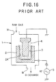
- An apparatus for forming the DLC film disclosed in the above publication comprises the followings. As shown in FIG. 16, a cathode 2 is disposed in a reaction chamber 1 having an inlet 1A for carbon resource gas which generates carbon or is converted to carbon and an outlet 1B, and a laboratory tool 3 such as a beaker is accommodated in a space 2A formed in the cathode 2.
- the reaction chamber 1 is decompressed by discharging air from the outlet 1B after an earthed anode 4 is inserted into an inner space of the laboratory tool 3.
- the reaction chamber 1 accommodates the cathode 2 and the anode 4, so that the volume of the reaction chamber 1 is remarkably large in comparison with that of the laboratory tool 3 to be coated. Therefore, it causes wastes of time and energy for a vacuum operation of the reaction chamber. Furthermore, since the film forming speed (rate) in the above DLC film forming apparatus is 10 to 1000 ⁇ per minute, which speed is slow, there is a problem in which it is difficult to continuously form the film at a low cost.
- the conventional DLC film forming apparatus described above is applied to laboratory tools such as beakers and flasks so as to mainly further increase their qualities, so that the manufacturing cost and time thereof is not much considered.
- containers used for beverages such as beer and orange juice must be manufactured in large quantities at low cost. Accordingly, the DLC film forming apparatus cannot be applied to the containers used for beverages.
- Containers for beverages are often collided and weared with each other in a manufacturing process in a factory or a selling process in a selling route, unlike the laboratory tool such as a beaker and a flask. Therefore, in case that the DLC film is formed on the outer surface of a container for beverages, the DLC film itself is damaged to decrease the value of merchandise of containers because the film is thin and hard. Accordingly, it is required that the DLC film is formed only on the inner surface of the container.
- This invention is made to overcome the above-mentioned conventional problems. More specifically, it is an object of this invention to provide an apparatus and a method for manufacturing a plastic container coated with carbon film which can solve the problems of gas barrier property and sorption inherently owned by the plastic while maintaining basic properties of plastic, which can be returnably used to extend the fields and the forms in which plastic containers can be used, which can be continuously manufactured at a low cost, and which is not damaged during handling of the containers.
- an apparatus of the invention for manufacturing a plastic container coated with carbon film which comprises: an external electrode having a hollow space approximately similar to an external shape of the container which is accommodated in the hollow space; an insulating member for insulating the external electrode, a mouth of the container abutting against the insulating member when the container is accommodated in the hollow space of the external electrode; an internal electrode inserted through the mouth of the container into the container accommodated in the hollow space of the external electrode, the internal electrode being earthed; discharging means communicated with the hollow space of the external electrode to discharge air in the hollow space; feeding means for feeding raw gas into the container accommodated in the hollow space of the external electrode; and a high frequency electric source connected to the external electrode.
- an apparatus of the invention for manufacturing a plastic container coated with carbon film which further comprises: the internal electrode has an external shape approximately similar to a shape of an inner surface of the container accommodated in the hollow space of the external electrode, the internal electrode has at least one blowing opening for blowing raw gas fed by the feeding means into the container accommodated in the hollow space in the external electrode, a plurality of the blowing openings are formed on the internal electrode, and the insulating member has at least one groove to communicate a space formed between an inner surface of the external electrode and an outer surface of the container with an interior of the container when the mouth of the container accommodated in the hollow space of the external electrode abuts against the insulating member.
- a method of the invention of manufacturing a plastic container coated with carbon film which comprises: providing, in an external electrode, a hollow space approximately similar to an external shape of a container, in which hollow space the container is accommodated; insulating the external electrode by an insulating member on which a mouth of the container abuts; inserting an internal electrode through the mouth of the container into the container accommodated in the hollow space, the internal electrode being earthed; [discharging air in the hollow space of the external electrode]; and impressing high frequency on the external electrode after raw gas is supplied into the container accommodated in the hollow space of the external electrode.
- the plastic container is inserted and accommodated in the external electrode.
- the internal electrode is inserted into the container. After the mouth of the container is abutted on the insulating member to be located in an appropriate position in the external electrode, the external electrode is tightly closed. In this situation, the distance between the inner surface of the external electrode and the outer surface of the container is maintained approximately even, and, the distance between the inner surface of the container and the outer surface of the internal electrode is also maintained approximately even.
- raw gas is fed by the feeding means to be blown off through blowing openings into the internal space in a state of vacuum.
- the container coated with carbon film can be produced continuously, at a low cost, for a short time, and without waste of energy. Furthermore, the carbon film can be formed only on the inner surface of the container.
- the carbon film can be formed uniformly on the inner surface of the container by forming the internal electrode so as to be approximately similar to the shape of the inner surface of the container.
- the raw gas is blown off evenly from the center portion of the container by forming blowing openings on the internal electrode, and, furthermore, diffusion of the raw gas is enhanced by forming a plurality of blowing openings.
- the formation of the grooves on the insulating member serves to make the space vacuum between the inner surface of the external electrode and the outer surface of the container whereby the temperature is suppressed to rise upon generating the plasma.
- a container manufactured by this invention is a bottle for beverages
- the container can be used as a returnable container in place of a conventional glass container.
- plasma treatment is performed by inorganic gas before the plastic container is coated with carbon film. This activates the inner surface of the container to enhance adhesion between the coated carbon film and the plastic material of the container.
- degree of vacuum falls within a range of 10 -2 to 10 -5 torr. This makes short the discharging time for a vacuum and saves necessary energy therefor.
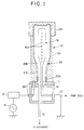
- FIG. 1 shows a manufacturing apparatus for manufacturing a plastic container coated with carbon film according to the invention.
- the manufacturing apparatus has a ceramic insulating plate 11 fixed on a base 10, on which insulating plate an external electrode 12 is mounted.
- the external electrode 12 itself serves at the same time as a vacuum chamber for forming a DLC film, inside of which external electrode a space is formed for accommodating a container 20 to be coated.
- the space formed in the external electrode 12 is slightly larger than the container 20 accommodated therein.
- the container 20 is a bottle for beverage, however, the container may be used for other objects.
- the external electrode 12 comprises a main body 12A and a cover 12B provided detachably on the main body 12A so as to tightly close the interior of the main body 12A.
- a high frequency power source 14 is connected to the lower portion of the external electrode 12 through a matching device 13 and connecting members 30, 30 provided on the base 10. Furthermore, a discharging pipe 15 is communicated as shown in FIG. 1 with the space formed in the external electrode 12 so as to discharge air in the space by a vacuum pump not shown.
- An internal electrode 16 is inserted into the space of the external electrode 12 so as to be disposed at the center portion of the space.
- the discharging pipe 15 terminates at the upper surface of the base 10 so as to be opened to a circular space 11B formed at the center portion of the insulating plate 11.
- the internal electrode 16 is so formed that the electrode 16 can be inserted into the container 20 through the mouth 20A of the container 20, and the external shape of the internal electrode 16 is approximately similar figures to the internal shape of the container 20. It is preferable that the distance between the external electrode 12 and the internal electrode 16 is kept approximately even at every position of the container 20 within the range of 10 - 150 mm.
- a feed pipe 17 for feeding raw gas is connected with the internal electrode 16.
- a raw gas is fed through a gas flow rate controller (not shown) from the feed pipe 17 for feeding raw gas into the internal electrode 16.
- the raw gas thus fed into the internal electrode 16 blows off from a plurality of blowing openings 16A formed on the internal electrode 16.
- a plurality of blowing openings are preferably formed on the side portion of the internal electrode 16 as shown in FIG. 1 in order to evenly diffuse the blown raw gas.
- one blowing opening may be formed on the top of the internal electrode 16.
- the internal electrode 16 is earthed through the feed pipe 17 for the raw gas.
- the insulating plate 11 comprises a short cylindrical body having an outer circumferential surface and an inner circumferential surface, and has a plurality of grooves 11A (four grooves in this embodiment) as enlargedly shown in FIGs. 2 and 3.
- Each of the grooves 11A is disposed at an angular interval of 90 ° and the bottom surface of each groove 11A is slanted downwardly from an abutting point P (FIG. 2) to the inner circumferential surface of the insulating plate 11, at which abutting point an inner circumferential surface of the external electrode 12 is abutted on the insulating plate 11.
- FIG. 2 As shown in FIG.
- an external space 21A formed between the inner surface of the external electrode 12 and the outer surface of the container 20 is communicated with the discharging pipe 15 through the grooves 11A in a state wherein the container 20 is accommodated in the external electrode 12 with the mouth 20A of the container 20 abutted against the insulating plate 11.
- the plastic container 20 is inserted from the upper opening of the main body 12A into the external electrode 12 with the cover 12B detached from the main body 12A.
- the internal electrode 16 is inserted into the container 20 through the mouth 20A of the container 20.
- the mouth 20A is abutted against the insulating plate 11 in such manner that the plastic container 20 is placed in an appropriate position in the external electrode 12, and the cover 12B then closes the upper opening of the main body 12A so that the external electrode 12 is tightly sealed.
- the distance between the inner surface of the external electrode 12 and the outer surface of the container 20 is maintained approximately even while the distance between the inner surface of the container 20 and the outer surface of the internal electrode 16 is maintained approximately even.
- the degree of vacuum is preferably within a range from 10 -2 to 10 -5 torr. With a lower degree of vacuum of over 10 -2 torr, impurities in the container are much increased, on the other hand, with a higher degree of vacuum under 10 -5 torr, a long time and a large energy are needed to discharge the air in the container 20.
- the raw gas as carbon resource is supplied to the feed pipe 17 through the gas flow rate controller not shown in the drawing, and then thus supplied raw gas is blown off through the blow openings 16A into the internal space 21B in the state of vacuum between the outer surface of the internal electrode 16 and the inner surface of the container 20.
- the flow rate of the raw gas is preferably within a range from 1 to 100 ml/min, by which flow rate of the raw gas the pressure in the internal space 21B is adjusted within the range from 0.5 to 0.001 torr.
- the pressure in the external space 21A becomes lower slightly later than the pressure in the internal space 21B becomes lower. Therefore, when the discharge of the air is just started, the pressure in the external space 21A is slightly higher than the pressure in the internal space 21B. Accordingly, in the case that the supply of the raw gas get started immediately after the discharge of the air in the container is over, the raw gas blown into the internal space 21B does not get into the external space 21A.
- Aliphatic hydrocarbons, aromatic hydrocarbons, oxygen containing hydrocarbons, nitrogen containing hydrocarbons, etc., in gaseous or liquid state at a room temperature are used as the raw gas.
- benzene, toluene, o-xylene, m-xylene, p-xylene and cyclohexane each having six or more than six carbons are preferable.
- These raw gases may be used per se, however, mixture of two or more than two kinds of raw gases may be used. Furthermore, these gases may be used in the state of dilution with inert gas such as argon and helium.
- the formation of the DLC film on the inner surface of the container 20 is performed by means of an improved plasma CVD method.
- a low temperature plasma is used in the plasma CVD method, the temperature upon forming the DLC film can be set relatively low. Therefore, the low temperature plasma is suitable in case that an article having a low thermal resistance such as plastic is used as a substrate, and furthermore, the low temperature plasma enables the DLC film to be formed on a wide area at a relatively low cost.
- the low temperature plasma is a plasma in the non-equilibrium state in which electron temperature is high in the plasma and temperatures of ion and neutral molecule are remarkably low in comparison with the temperature of the electron in case that the interior of the reaction chamber is maintained at a low pressure.
- the hard carbon film of the DLC film is also called as i-carbon film or hydrogenated amorphous carbon film (a-C:H) and is an amorphous carbon film including mainly SP 3 bond.
- the thickness of DLC film is varied by an output of high frequency, a pressure of the raw gas in the container 20, a gas flow rate for feeding, period of time during which plasma is generated, self-bias and kind of raw material and the like.
- the thickness of DLC film is preferably within a range from 0.05 to 5 ⁇ m to obtain the effective suppression of the sorption of the low molecular organic compound and the improved gas barrier property, in addition to an excellent adhesion to plastic, a good durability and a good transparency.
- Quality of the DLC film is varied by output of the high frequency, the pressure of the raw gas in the container 20, the gas flow rate, the period of time during which plasma is generated, the self-bias and the kind of raw material in the same manner.
- the output of high frequency is set within a range from 50 to 1,000 W
- the pressure of raw gas in the container 20 is set within a range from 0.2 to 0.01 torr
- the flow rate of supplied gas is set within a range from 10 to 50 ml/min
- the self-bias is set within a range from -200 to -1,000V
- the carbon number is set within a range from 1 to 8.
- the inner surface of the container 20 may be activated by plasma treatment with inorganic gas such as argon and oxygen before DLC film is formed.
- FIG. 4 shows a longitudinal section of plastic container on which the DLC film is formed in the above manner.
- numeral numbers 20a and 20b show a plastic material and a DLC film formed on the inner surface of the plastic material 20a, respectively.
- the plastic container whose inner surface is coated with the DLC film 20b can remarkably decrease permeability of low molecular inorganic gas such as oxygen and carbon dioxide, and simultaneously can completely suppress the sorption of various low molecular organic compounds having odor. Formation of the DLC film does not deteriorate transparency of the plastic container.
- the following resins are used as plastic materials for containers 20: polyethylene resin, polypropylene resin, polystyrene resin, cycloolefine copolymer resin, polyethylene terephthalate resin, polyethylene naphthalate resin, ethylene-(vinyl alcohol) copolymer resin, poly-4-methylpentene-1 resin, poly (methyl methacrylate) resin, acrylonitrile resin, polyvinyl chloride resin, polyvinylidene chloride resin, styrene-acrylo nitrile resin, acrylonitrile-butadien-styrene resin, polyamide resin, polyamideimide resin, polyacetal resin, polycarbonate resin, polybutylene terephthalate resin, ionomer resin, polysulfone resin, polytetra fluoroethylene resin and the like.
- Masking was previously made by Magic Marker (trade mark) on the inner surface of the container, and the DLC film was then formed. Thereafter, the masking was removed by diethyl ether, and thickness of the DLC film was measured by a surface shape measuring device (DECTACK 3) made by Vecco Company.
- DECTACK 3 surface shape measuring device
- Adhesion of the DLC film formed on the side surface of the container was measured in accordance with cross-cut tape test (JIS K 5400) under the following conditions.
- Adhesion of the DLC film formed on the side surface of the container was measured by a continuously weighting type scratch tester (HEIDON 22) made by SHINTO KAGAKU company under the following conditions. Degree of adhesion was indicated by normal load exerted on a scratching needle when the film was started to be peeled off.
- Alkali solution including sodium hydroxide of 10 wt% was filled into the container which was then immersed in a water bath at a temperature of 75 °C for 24 hours. Then, change of shape of the DLC film and existence of peeling of the DLC film were investigated. "Excellence" in the table shows that shape of DLC film was not changed and peeling thereof did not occur after the immersion for over 24 hours.
- volume of carbon dioxide permeating the DLC film was measured by a PERMA TRANC - 4 type machine made by MODERN CONTROL Company at a temperature of 25°C.
- volume of oxygen permeating the DLC film was measured by an OXTRANTWIN machine made by MODERN CONTROL Company at a temperature of 40°C.
- Low molecular organic compound (aroma component) having odor was used as a kind of environmental material to test the sorption with reference to a method by MATSUI et al. (J. Agri. Food. Chem., 1992, 40, 1902 - 1905) in the following manner.
- a plastic container having a volume of 700 ml and made of polyethylene terephthalate resin (PET resin, Type L125 made by MITSUI PET RESIN COMPANY LIMITED) was accommodated in the external electrode 12 as shown in FIG. 1 to be fixed thereto.
- PET resin polyethylene terephthalate resin
- the vacuum pump was operated to make the inside of the external electrode 12 vacuum (back pressure) of lower than 10 -4 torr, and, thereafter, for preliminary treatment, argon was supplied into the plastic container at a flow rate of 30 ml/min to obtain a pressure of 0.04 torr in the container, and Rf power of 300W was supplied to perform plasma treatment on the inner surface of the container. Thereafter, raw gas such as toluene, cyclohexane, benzene or p-xylene was supplied into the interior of the container with using argon as auxiliary gas to uniformly form the DLC film on the inner surface of the container under the conditions shown in FIG. 5.
- FIG. 6 shows the results of the evaluation with respect to thickness of film, film forming velocity, density of film, adhesion 1 of film, adhesion 2 of film and alkali resistance of film.
- the density of each film exceeded 2.00 g/cm 3 , and the formed film was remarkably dense.
- the adhesion to polyethylene terephthalate resin was good, and it was verified that the container was sufficient to be of practical use. Furthermore, it was found that alkali resistance was good, and the DLC film was stable enough to completely protect the polyethylene terephthalate resin.
- FIG. 8 shows the transmitted light spectrum in ultraviolet and visible region at the barrel portion of the plastic container, the inner surface of which was coated with the DLC film.
- Light transmittance rate was abruptly decreased in a region from approximately 500 nm of wave length to the ultraviolet region. This suggests that the coating with the use of the DLC film is effective enough to suppress the deterioration of contents by ultraviolet.
- FIG. 9 shows Raman spectrum of the thin film formed on the barrel portion of the plastic container under the conditions of Test 1.
- the DLC film was formed on the inner surface of the container in the same manner as Test 1 except that a plastic container, having a volume of 700 ml made of styrene-acrylonitrile copolymer resin (made by Mitsubishi Monsant Kasei Company: PAN resin, type L700) was used.
- the conditions for forming the DLC film are shown in FIG. 10.
- tests were performed in connection with the DLC film, namely, thickness, density, adhesion 1, adhesion 2, alkali resistance, carbon dioxide barrier property, oxygen gas barrier property and sorption of low molecular organic compound.
- FIG. 12 shows oxygen permeability, carbon dioxide permeability and degree of sorption of each aroma component. More specifically, it was found that stylene-acrylonitrile copolymer resin was inherently excellent in gas barrier property, and further, the permeating amount of each of oxygen and carbon dioxide with respect to stylene-acrylonitrile copolymer resin was remarkably decreased to an extremely lower level by the formation of the DLC film. Amount of the sorption of each aroma component was smaller than the detectable limit, and there was no problem in sensory test in the same way as Test 1.
- the DLC film was formed on the inner surface of the container in the same manner as Test 1 except that a plastic container having a volume of 700 ml made of cycloolefine copolymer resin (made by MITSUI PETROCHEMICAL COMPANY LIMITED: COC resin, type APL 6015) was used.
- the conditions for forming the DLC film are shown in FIG. 13.
- tests were performed in connection with the DLC film, namely, thickness of film, density of film, adhesion 1 of film, adhesion 2 of film, alkali resistance of film, carbon dioxide barrier property of film, oxygen gas barrier property of film and sorption of film to low molecular organic compound.
- FIG. 15 shows results of the oxygen permeability of the DLC film, the carbon dioxide permeability thereof and the sorption of each aroma component.
- Cycloolefine copolymer resin has comparatively large oxygen permeability, carbon dioxide permeability and sorption of aroma components because it is olefine type resin.
- the formation of the DLC film on the container could considerably suppress the oxygen permeability, the carbon dioxide permeability and the sorption of aroma components.
- the apparatus and the method for manufacturing a plastic container coated with carbon film of the invention can be used for manufacturing a returnable container such as a bottle for beer, sake as well as beverage.
Landscapes
- Chemical & Material Sciences (AREA)
- Engineering & Computer Science (AREA)
- Mechanical Engineering (AREA)
- General Chemical & Material Sciences (AREA)
- Chemical Kinetics & Catalysis (AREA)
- Materials Engineering (AREA)
- Metallurgy (AREA)
- Organic Chemistry (AREA)
- Physics & Mathematics (AREA)
- Analytical Chemistry (AREA)
- Plasma & Fusion (AREA)
- Wood Science & Technology (AREA)
- Life Sciences & Earth Sciences (AREA)
- Inorganic Chemistry (AREA)
- Ceramic Engineering (AREA)
- Details Of Rigid Or Semi-Rigid Containers (AREA)
- Chemical Vapour Deposition (AREA)
- Containers Having Bodies Formed In One Piece (AREA)
- Carbon And Carbon Compounds (AREA)
- Blow-Moulding Or Thermoforming Of Plastics Or The Like (AREA)
Applications Claiming Priority (4)
| Application Number | Priority Date | Filing Date | Title |
|---|---|---|---|
| JP189224/94 | 1994-08-11 | ||
| JP18922494 | 1994-08-11 | ||
| JP6189224A JP2788412B2 (ja) | 1994-08-11 | 1994-08-11 | 炭素膜コーティングプラスチック容器の製造装置および製造方法 |
| PCT/JP1995/001583 WO1996005112A1 (fr) | 1994-08-11 | 1995-08-09 | Recipients de plastique a revetement mince de carbone, leur appareil de fabrication et procede associe |
Publications (3)
| Publication Number | Publication Date |
|---|---|
| EP0773167A1 true EP0773167A1 (de) | 1997-05-14 |
| EP0773167A4 EP0773167A4 (de) | 1999-08-18 |
| EP0773167B1 EP0773167B1 (de) | 2002-10-16 |
Family
ID=16237661
Family Applications (1)
| Application Number | Title | Priority Date | Filing Date |
|---|---|---|---|
| EP95927997A Expired - Lifetime EP0773167B1 (de) | 1994-08-11 | 1995-08-09 | Verfahren und vorrichtung zur herstellung eines mit kohlenstoffilm beschichteten kunststoffbehälters |
Country Status (11)
| Country | Link |
|---|---|
| US (1) | US5798139A (de) |
| EP (1) | EP0773167B1 (de) |
| JP (1) | JP2788412B2 (de) |
| KR (1) | KR100347249B1 (de) |
| AT (1) | ATE226166T1 (de) |
| CA (1) | CA2196894C (de) |
| DE (1) | DE69528588T2 (de) |
| DK (1) | DK0773167T3 (de) |
| MY (1) | MY113185A (de) |
| TW (1) | TW493012B (de) |
| WO (1) | WO1996005112A1 (de) |
Cited By (15)
| Publication number | Priority date | Publication date | Assignee | Title |
|---|---|---|---|---|
| WO1999017334A1 (en) * | 1997-09-30 | 1999-04-08 | Tetra Laval Holdings & Finance S.A. | Method and apparatus for treating the inside surface of plastic bottles in a plasma enhanced process |
| WO2001056706A1 (de) * | 2000-02-01 | 2001-08-09 | Tetra Laval Holdings & Finance S.A. | Vorrichtung zum beschichten der inneren oberfläche eines hohlkörpers |
| WO2002010474A1 (fr) * | 2000-08-01 | 2002-02-07 | Sidel | Procede de revetement par plasma |
| AU744162B2 (en) * | 1997-02-19 | 2002-02-14 | Kirin Beer Kabushiki Kaisha | Method and apparatus for producing plastic container having carbon film coating |
| FR2814382A1 (fr) * | 2000-09-28 | 2002-03-29 | Cebal | Procede de depot d'un revetement interne dans un recipient en matiere plastique |
| EP1197581A1 (de) * | 1999-05-19 | 2002-04-17 | Mitsubishi Shoji Plastics Corporation | Dlc-film, dlc-beschichteter plastikbehälter und verfahren und vorrichtung zur herstellung solcher behälter |
| WO2002036850A2 (de) * | 2000-11-03 | 2002-05-10 | Vereinigung Zur Förderung Des Instituts Für Kunststoffverarbeitung In Industrie Und Handwerk An Der Rheinisch-Westfälischen Rwth Aachen E.V. | Verfahren und vorrichtung zum beschichten von hohlkörpern |
| WO2004024577A3 (de) * | 2002-09-11 | 2004-07-22 | Sig Technology Ltd | Behalter zur verpackung von produkten, vorrichtung zur verarbeitung von kunststoff sowie verfahren zur behalterherstellung |
| AU776224B2 (en) * | 1997-02-19 | 2004-09-02 | Kirin Beer Kabushiki Kaisha | Apparatus and method for manufacturing plastic container coated with carbon film |
| EP1508630A1 (de) * | 2002-05-28 | 2005-02-23 | Kirin Brewery Company, Ltd. | Vorrichtung zur herstellung eines mit einem dlc-film beschichteten kunststoffbehälters |
| FR2872718A1 (fr) * | 2004-07-08 | 2006-01-13 | Sidel Sa Sa | Procede de traitement d'un recipient comportant des phases de pompage a vide et machine pour sa mise en oeuvre |
| WO2007022976A2 (de) | 2005-08-24 | 2007-03-01 | Schott Ag | Verfahren und vorrichtung zur innenseitigen plasmabehandlung von hohlkörpern |
| WO2007029050A1 (en) * | 2005-09-09 | 2007-03-15 | Sidel | Barrier layer |
| CN100386155C (zh) * | 2001-08-07 | 2008-05-07 | 肖特股份公司 | 同时对物体进行涂层和成型的方法与装置 |
| US8883257B2 (en) | 2009-04-13 | 2014-11-11 | Kirin Beer Kabushiki Kaisha | Method for manufacturing gas barrier thin film-coated plastic container |
Families Citing this family (58)
| Publication number | Priority date | Publication date | Assignee | Title |
|---|---|---|---|---|
| JPH0853116A (ja) | 1994-08-11 | 1996-02-27 | Kirin Brewery Co Ltd | 炭素膜コーティングプラスチック容器 |
| US5965217A (en) * | 1996-10-08 | 1999-10-12 | Citizen Watch Co., Ltd. | Method of forming DLC films over inner surface of cylindrical member |
| US5879763A (en) * | 1997-09-03 | 1999-03-09 | Citizen Watch Co., Ltd. | Method of forming hard carbon film over inner surface of cylindrical member |
| JP3669138B2 (ja) | 1998-03-05 | 2005-07-06 | 日新電機株式会社 | プラズマcvd法、プラズマcvd装置及び電極 |
| US6277480B1 (en) | 1999-05-03 | 2001-08-21 | Guardian Industries Corporation | Coated article including a DLC inclusive layer(s) and a layer(s) deposited using siloxane gas, and corresponding method |
| US6461731B1 (en) | 1999-05-03 | 2002-10-08 | Guardian Industries Corp. | Solar management coating system including protective DLC |
| US6368664B1 (en) | 1999-05-03 | 2002-04-09 | Guardian Industries Corp. | Method of ion beam milling substrate prior to depositing diamond like carbon layer thereon |
| US6447891B1 (en) | 1999-05-03 | 2002-09-10 | Guardian Industries Corp. | Low-E coating system including protective DLC |
| US6335086B1 (en) | 1999-05-03 | 2002-01-01 | Guardian Industries Corporation | Hydrophobic coating including DLC on substrate |
| US6312808B1 (en) | 1999-05-03 | 2001-11-06 | Guardian Industries Corporation | Hydrophobic coating with DLC & FAS on substrate |
| US6475573B1 (en) | 1999-05-03 | 2002-11-05 | Guardian Industries Corp. | Method of depositing DLC inclusive coating on substrate |
| US6261693B1 (en) | 1999-05-03 | 2001-07-17 | Guardian Industries Corporation | Highly tetrahedral amorphous carbon coating on glass |
| US6280834B1 (en) | 1999-05-03 | 2001-08-28 | Guardian Industries Corporation | Hydrophobic coating including DLC and/or FAS on substrate |
| US6475579B1 (en) * | 1999-08-06 | 2002-11-05 | Plastipak Packaging, Inc. | Multi-layer plastic container having a carbon-treated internal surface and method for making the same |
| WO2001010725A1 (en) | 1999-08-06 | 2001-02-15 | Plastipak Packaging, Inc. | Plastic container having a carbon-treated internal surface |
| FR2799994B1 (fr) * | 1999-10-25 | 2002-06-07 | Sidel Sa | Dispositif pour le traitement d'un recipient a l'aide d'un plasma a basse pression comportant un circuit de vide perfectionne |
| DE19957744A1 (de) * | 1999-12-01 | 2001-06-07 | Tetra Laval Holdings & Finance | Vorrichtung zum Abdichten des Stirnrandes eines Behälterhalses |
| US6528947B1 (en) | 1999-12-06 | 2003-03-04 | E. I. Du Pont De Nemours And Company | Hollow cathode array for plasma generation |
| WO2001047777A1 (fr) * | 1999-12-27 | 2001-07-05 | Mitsubishi Shoji Plastics Corporation | Conteneur en pet pour aliments et boissons contenant de la resine recyclee et presentant un film de revetement en cda forme sur la surface du film |
| JP4492985B2 (ja) | 2000-02-24 | 2010-06-30 | 三菱商事プラスチック株式会社 | 液体医薬品用プラスチック容器及び液体医薬品の保存回収方法 |
| JP2001240115A (ja) * | 2000-02-24 | 2001-09-04 | Mitsubishi Shoji Plast Kk | 乾燥固体食品用プラスチック容器 |
| JP2001322656A (ja) * | 2000-05-15 | 2001-11-20 | Hokkai Can Co Ltd | 合成樹脂製キャップ |
| JP3993971B2 (ja) * | 2000-08-09 | 2007-10-17 | 北海製罐株式会社 | ガスバリア被覆層を有するプラスチック製容器及びその製法 |
| US6461699B1 (en) * | 2000-10-06 | 2002-10-08 | Plastipak Packaging, Inc. | Plastic container having a carbon-treated internal surface for non-carbonated food products |
| WO2002049925A1 (fr) * | 2000-12-21 | 2002-06-27 | Mitsubishi Shoji Plastics Corporation | Appareil de fabrication de recipients de plastique revetus de dlc leur procede de fabrication associe et procede de nettoyage de l'electrode interieure |
| JP4850385B2 (ja) | 2000-12-25 | 2012-01-11 | 三菱商事プラスチック株式会社 | Dlc膜コーティングプラスチック容器の製造装置及びその製造方法 |
| JP4678959B2 (ja) * | 2001-02-05 | 2011-04-27 | サムコ株式会社 | プラスチック容器の壁面への成膜方法、成膜装置及びプラスチック容器 |
| CN1228213C (zh) | 2001-04-19 | 2005-11-23 | 日精Asb机械株式会社 | 气障性合成树脂制容器及其制造装置以及装入物品的气障性合成树脂制容器 |
| JP4659279B2 (ja) * | 2001-06-19 | 2011-03-30 | 北海製罐株式会社 | プラスチック製ボトルの内面被膜検査方法 |
| JPWO2003000558A1 (ja) * | 2001-06-20 | 2004-10-07 | 三菱商事プラスチック株式会社 | 間仕切板付き水分・ガスバリア性プラスチック容器、その製造装置及びその製造方法 |
| WO2003000559A1 (fr) * | 2001-06-26 | 2003-01-03 | Mitsubishi Shoji Plastics Corporation | Dispositif de fabrication d'un recipient en plastique revetu d'un film de carbone sous forme de diamant amorphe, recipient ainsi obtenu et procede de fabrication dudit recipient |
| JP3653035B2 (ja) * | 2001-07-31 | 2005-05-25 | 三菱重工業株式会社 | プラスチック容器内面への炭素膜形成装置および内面炭素膜被覆プラスチック容器の製造方法 |
| DE10139305A1 (de) * | 2001-08-07 | 2003-03-06 | Schott Glas | Verbundmaterial aus einem Substratmaterial und einem Barriereschichtmaterial |
| DE10138697B4 (de) * | 2001-08-07 | 2005-02-24 | Schott Ag | Verfahren und Vorrichtung zum Beschichten und Spritzblasen eines dreidimensionalen Körpers |
| DE10204363A1 (de) * | 2002-02-02 | 2003-08-14 | Schott Glas | Interferenzbeschichtung zur Verbesserung des Energiehaushaltes von HID-Lampen |
| AU2002249596A1 (en) * | 2002-04-15 | 2003-10-27 | Mitsubishi Shoji Plastics Corporation | System and method for forming dlc film on inner surface of plastic container |
| JP4654027B2 (ja) * | 2002-05-24 | 2011-03-16 | カーハーエス コーポプラスト ゲーエムベーハー ウント コンパニー カーゲー | 工作物のプラズマ処理方法および装置 |
| DE60336808D1 (de) | 2002-05-28 | 2011-06-01 | Kirin Brewery | Vorrichtung zur Beschichtung eines Kunststoffbehälters mit einer diamantähnlichen Kohlenstoffschicht |
| AU2003242357A1 (en) | 2002-06-05 | 2003-12-22 | Kirin Brewery Company, Limited | Method and device for cleaning raw material gas introduction tube used in cvd film forming apparatus |
| JP4149748B2 (ja) | 2002-06-24 | 2008-09-17 | 三菱商事プラスチック株式会社 | ロータリー型量産用cvd成膜装置及びプラスチック容器内表面へのcvd膜成膜方法 |
| CN100445423C (zh) | 2002-09-30 | 2008-12-24 | 凸版印刷株式会社 | 薄膜成膜方法、薄膜成膜装置和薄膜成膜过程的监视方法 |
| US7513953B1 (en) * | 2003-11-25 | 2009-04-07 | Nano Scale Surface Systems, Inc. | Continuous system for depositing films onto plastic bottles and method |
| JP4171452B2 (ja) | 2004-10-18 | 2008-10-22 | 三菱重工食品包装機械株式会社 | バリア膜形成用内部電極及び成膜装置 |
| US20060198973A1 (en) * | 2005-03-03 | 2006-09-07 | Jester Randy D | Packaging with cycloolefin food/beverage contact layer |
| JP5260050B2 (ja) | 2005-05-27 | 2013-08-14 | 麒麟麦酒株式会社 | ガスバリア性プラスチック容器の製造装置及びその容器の製造方法 |
| JP5355860B2 (ja) * | 2007-03-16 | 2013-11-27 | 三菱重工食品包装機械株式会社 | バリア膜形成装置、バリア膜形成方法及びバリア膜被覆容器 |
| DE102007041573A1 (de) | 2007-09-01 | 2009-03-05 | Khs Corpoplast Gmbh & Co. Kg | Verfahren und Vorrichtung zum Sterilisieren sowie Vorrichtung zur Blasformung von Behältern |
| DE102008037159A1 (de) * | 2008-08-08 | 2010-02-11 | Krones Ag | Vorrichtung und Verfahren zur Plasmabehandlung von Hohlkörpern |
| JP5795266B2 (ja) | 2009-02-18 | 2015-10-14 | カウンシル オブ サイエンティフィック アンド インダストリアル リサーチ | 成形された物体の内側表面上に、保護被膜としてダイヤモンド状炭素を堆積する方法 |
| JP4873037B2 (ja) * | 2009-03-31 | 2012-02-08 | 東洋製罐株式会社 | 非耐圧性プラスチック容器 |
| US20110001103A1 (en) * | 2009-07-01 | 2011-01-06 | Chi-Kuang Chen | Elevating mechanism for measuring concentrations of medicines |
| DE102012201955A1 (de) * | 2012-02-09 | 2013-08-14 | Krones Ag | Powerlanze und plasmaunterstützte Beschichtung mit Hochfrequenzeinkopplung |
| DE102012201956A1 (de) * | 2012-02-09 | 2013-08-14 | Krones Ag | Hohlkathoden-Gaslanze für die Innenbeschichtung von Behältern |
| JP6047308B2 (ja) | 2012-05-28 | 2016-12-21 | 日精エー・エス・ビー機械株式会社 | 樹脂容器用コーティング装置 |
| JP6093552B2 (ja) * | 2012-11-08 | 2017-03-08 | 日精エー・エス・ビー機械株式会社 | 樹脂容器用コーティング装置 |
| CN103014652B (zh) * | 2012-12-07 | 2016-01-20 | 中国电子科技集团公司第十一研究所 | 单晶生长用石英安瓿内壁碳膜制备装置 |
| ITFI20130001A1 (it) * | 2013-01-02 | 2014-07-03 | Enomatic S R L | Dispositivo erogatore di bevande gassate. |
| CN104368482B (zh) * | 2014-11-11 | 2016-06-29 | 深圳格普斯电热技术有限公司 | 电热膜的内壁喷涂装置及其喷涂方法 |
Citations (11)
| Publication number | Priority date | Publication date | Assignee | Title |
|---|---|---|---|---|
| EP0304220A1 (de) * | 1987-08-10 | 1989-02-22 | Semiconductor Energy Laboratory Co., Ltd. | Dünnfilmkohlewerkstoff und Verfahren zum Aufbringen |
| EP0348690A2 (de) * | 1988-07-01 | 1990-01-03 | Becton, Dickinson and Company | Vorrichtung und Verfahren für die Plasmabehandlung dünner Schläuche |
| JPH0270059A (ja) * | 1987-12-02 | 1990-03-08 | Idemitsu Petrochem Co Ltd | 器具およびその製造方法 |
| EP0359567A2 (de) * | 1988-09-16 | 1990-03-21 | Semiconductor Energy Laboratory Co., Ltd. | Verfahren und Vorrichtung zur Plasmabehandlung |
| EP0372696A2 (de) * | 1988-10-11 | 1990-06-13 | Semiconductor Energy Laboratory Co., Ltd. | Verfahren zur Herstellung eines kohlenstoffhaltigen Films |
| US5007374A (en) * | 1988-03-22 | 1991-04-16 | Semiconductor Energy Laboratory Co., Ltd. | Apparatus for forming thin films in quantity |
| US5112025A (en) * | 1990-02-22 | 1992-05-12 | Tdk Corporation | Molds having wear resistant release coatings |
| US5169452A (en) * | 1990-05-14 | 1992-12-08 | Tdk Corporation | Apparatus for the synthesis of diamond-like thin films |
| WO1993024243A1 (en) * | 1992-05-28 | 1993-12-09 | Polar Materials, Inc. | Methods and apparatus for depositing barrier coatings |
| WO1994000247A1 (en) * | 1992-06-26 | 1994-01-06 | Polar Materials, Inc. | Methods and apparatus for externally treating a container with application of internal bias gas |
| EP0605814A1 (de) * | 1993-01-07 | 1994-07-13 | International Business Machines Corporation | Diamantähnliche Kohlenstoffilme hergestellt aus einem Kohlenwasserstoff-Helium-Plasma |
Family Cites Families (10)
| Publication number | Priority date | Publication date | Assignee | Title |
|---|---|---|---|---|
| JPS60228250A (ja) * | 1984-04-24 | 1985-11-13 | テルモ株式会社 | 合成樹脂製容器の製造方法 |
| FR2592874B1 (fr) * | 1986-01-14 | 1990-08-03 | Centre Nat Rech Scient | Procede pour tremper un objet en verre ou vitreux et objet ainsi trempe |
| JPH01100277A (ja) * | 1987-10-12 | 1989-04-18 | Idemitsu Petrochem Co Ltd | 硬質炭素膜付着湾曲板、硬質炭素膜付着湾曲板の製造方法および硬質炭素膜付着湾曲板の製造装置 |
| JPH0627342B2 (ja) * | 1988-02-05 | 1994-04-13 | 株式会社半導体エネルギー研究所 | 炭素膜形成方法 |
| US4859489A (en) * | 1988-07-18 | 1989-08-22 | Vapor Technologies Inc. | Method of coating a metal gas-pressure bottle or tank |
| JPH02138469A (ja) * | 1988-11-16 | 1990-05-28 | Hitachi Ltd | ダイアモンド表面を有する真空用材料、この真空用材料の表面処理法、ダイアモンド膜表面の作製法、真空用材料を用いた真空容器とその部品,真空内駆動機構,電子放出源,真空内ヒータおよび蒸着源容器 |
| JPH03130363A (ja) * | 1989-10-16 | 1991-06-04 | Nikon Corp | ダイヤモンド状炭素膜被覆プラスチツック物品 |
| US5190807A (en) * | 1990-10-18 | 1993-03-02 | Diamonex, Incorporated | Abrasion wear resistant polymeric substrate product |
| JPH04304373A (ja) * | 1991-03-29 | 1992-10-27 | Shimadzu Corp | 硬質カーボン膜形成方法 |
| US5565248A (en) * | 1994-02-09 | 1996-10-15 | The Coca-Cola Company | Method and apparatus for coating hollow containers through plasma-assisted deposition of an inorganic substance |
-
1994
- 1994-08-11 JP JP6189224A patent/JP2788412B2/ja not_active Expired - Lifetime
-
1995
- 1995-07-13 TW TW084107275A patent/TW493012B/zh not_active IP Right Cessation
- 1995-08-09 WO PCT/JP1995/001583 patent/WO1996005112A1/ja active IP Right Grant
- 1995-08-09 AT AT95927997T patent/ATE226166T1/de active
- 1995-08-09 KR KR1019970700628A patent/KR100347249B1/ko not_active IP Right Cessation
- 1995-08-09 US US08/776,703 patent/US5798139A/en not_active Expired - Lifetime
- 1995-08-09 EP EP95927997A patent/EP0773167B1/de not_active Expired - Lifetime
- 1995-08-09 DE DE69528588T patent/DE69528588T2/de not_active Expired - Lifetime
- 1995-08-09 DK DK95927997T patent/DK0773167T3/da active
- 1995-08-09 CA CA002196894A patent/CA2196894C/en not_active Expired - Fee Related
- 1995-08-11 MY MYPI95002345A patent/MY113185A/en unknown
Patent Citations (11)
| Publication number | Priority date | Publication date | Assignee | Title |
|---|---|---|---|---|
| EP0304220A1 (de) * | 1987-08-10 | 1989-02-22 | Semiconductor Energy Laboratory Co., Ltd. | Dünnfilmkohlewerkstoff und Verfahren zum Aufbringen |
| JPH0270059A (ja) * | 1987-12-02 | 1990-03-08 | Idemitsu Petrochem Co Ltd | 器具およびその製造方法 |
| US5007374A (en) * | 1988-03-22 | 1991-04-16 | Semiconductor Energy Laboratory Co., Ltd. | Apparatus for forming thin films in quantity |
| EP0348690A2 (de) * | 1988-07-01 | 1990-01-03 | Becton, Dickinson and Company | Vorrichtung und Verfahren für die Plasmabehandlung dünner Schläuche |
| EP0359567A2 (de) * | 1988-09-16 | 1990-03-21 | Semiconductor Energy Laboratory Co., Ltd. | Verfahren und Vorrichtung zur Plasmabehandlung |
| EP0372696A2 (de) * | 1988-10-11 | 1990-06-13 | Semiconductor Energy Laboratory Co., Ltd. | Verfahren zur Herstellung eines kohlenstoffhaltigen Films |
| US5112025A (en) * | 1990-02-22 | 1992-05-12 | Tdk Corporation | Molds having wear resistant release coatings |
| US5169452A (en) * | 1990-05-14 | 1992-12-08 | Tdk Corporation | Apparatus for the synthesis of diamond-like thin films |
| WO1993024243A1 (en) * | 1992-05-28 | 1993-12-09 | Polar Materials, Inc. | Methods and apparatus for depositing barrier coatings |
| WO1994000247A1 (en) * | 1992-06-26 | 1994-01-06 | Polar Materials, Inc. | Methods and apparatus for externally treating a container with application of internal bias gas |
| EP0605814A1 (de) * | 1993-01-07 | 1994-07-13 | International Business Machines Corporation | Diamantähnliche Kohlenstoffilme hergestellt aus einem Kohlenwasserstoff-Helium-Plasma |
Non-Patent Citations (2)
| Title |
|---|
| PATENT ABSTRACTS OF JAPAN vol. 014, no. 254 (C-0724), 31 May 1990 -& JP 02 070059 A (IDEMITSU PETROCHEM CO LTD), 8 March 1990 * |
| See also references of WO9605112A1 * |
Cited By (27)
| Publication number | Priority date | Publication date | Assignee | Title |
|---|---|---|---|---|
| AU744162B2 (en) * | 1997-02-19 | 2002-02-14 | Kirin Beer Kabushiki Kaisha | Method and apparatus for producing plastic container having carbon film coating |
| AU776224B2 (en) * | 1997-02-19 | 2004-09-02 | Kirin Beer Kabushiki Kaisha | Apparatus and method for manufacturing plastic container coated with carbon film |
| WO1999017334A1 (en) * | 1997-09-30 | 1999-04-08 | Tetra Laval Holdings & Finance S.A. | Method and apparatus for treating the inside surface of plastic bottles in a plasma enhanced process |
| US6565791B1 (en) | 1997-09-30 | 2003-05-20 | Tetra Laval Holdings & Finance S.A. | Method and apparatus for treating the inside surface of plastic bottles in a plasma enhanced process |
| EP1197581A1 (de) * | 1999-05-19 | 2002-04-17 | Mitsubishi Shoji Plastics Corporation | Dlc-film, dlc-beschichteter plastikbehälter und verfahren und vorrichtung zur herstellung solcher behälter |
| EP1197581A4 (de) * | 1999-05-19 | 2002-10-30 | Mitsubishi Shoji Plastics Corp | Dlc-film, dlc-beschichteter plastikbehälter und verfahren und vorrichtung zur herstellung solcher behälter |
| WO2001056706A1 (de) * | 2000-02-01 | 2001-08-09 | Tetra Laval Holdings & Finance S.A. | Vorrichtung zum beschichten der inneren oberfläche eines hohlkörpers |
| WO2002010474A1 (fr) * | 2000-08-01 | 2002-02-07 | Sidel | Procede de revetement par plasma |
| FR2812665A1 (fr) * | 2000-08-01 | 2002-02-08 | Sidel Sa | Procede de depot de revetement par plasma, dispositif de mise en oeuvre du procede et revetement obtenu par un tel procede |
| FR2814382A1 (fr) * | 2000-09-28 | 2002-03-29 | Cebal | Procede de depot d'un revetement interne dans un recipient en matiere plastique |
| WO2002026401A1 (fr) * | 2000-09-28 | 2002-04-04 | Cebal Sa | Procede de depot d'un revetement interne dans un recipient en matiere plastique |
| WO2002036850A3 (de) * | 2000-11-03 | 2002-07-18 | Ver Foerderung Inst Kunststoff | Verfahren und vorrichtung zum beschichten von hohlkörpern |
| WO2002036850A2 (de) * | 2000-11-03 | 2002-05-10 | Vereinigung Zur Förderung Des Instituts Für Kunststoffverarbeitung In Industrie Und Handwerk An Der Rheinisch-Westfälischen Rwth Aachen E.V. | Verfahren und vorrichtung zum beschichten von hohlkörpern |
| CN100386155C (zh) * | 2001-08-07 | 2008-05-07 | 肖特股份公司 | 同时对物体进行涂层和成型的方法与装置 |
| EP1508630A4 (de) * | 2002-05-28 | 2007-07-18 | Kirin Brewery | Vorrichtung zur herstellung eines mit einem dlc-film beschichteten kunststoffbehälters |
| EP1508630A1 (de) * | 2002-05-28 | 2005-02-23 | Kirin Brewery Company, Ltd. | Vorrichtung zur herstellung eines mit einem dlc-film beschichteten kunststoffbehälters |
| WO2004024577A3 (de) * | 2002-09-11 | 2004-07-22 | Sig Technology Ltd | Behalter zur verpackung von produkten, vorrichtung zur verarbeitung von kunststoff sowie verfahren zur behalterherstellung |
| EP1773512A1 (de) * | 2004-07-08 | 2007-04-18 | Sidel Participations | Behälterbehandlungsverfahren mit vakuumpumpphasen und maschine zu dessen ausführung |
| WO2006005698A1 (fr) * | 2004-07-08 | 2006-01-19 | Sidel Participations | Procede de traitement d'un recipient comportant des phases de pompage a vide et machine pour sa mise en oeuvre |
| FR2872718A1 (fr) * | 2004-07-08 | 2006-01-13 | Sidel Sa Sa | Procede de traitement d'un recipient comportant des phases de pompage a vide et machine pour sa mise en oeuvre |
| US7838071B2 (en) | 2004-07-08 | 2010-11-23 | Sidel Participations | Container-treatment method comprising vacuum pumping phases, and machine for implementing same |
| WO2007022976A2 (de) | 2005-08-24 | 2007-03-01 | Schott Ag | Verfahren und vorrichtung zur innenseitigen plasmabehandlung von hohlkörpern |
| WO2007022976A3 (de) * | 2005-08-24 | 2007-04-26 | Schott Ag | Verfahren und vorrichtung zur innenseitigen plasmabehandlung von hohlkörpern |
| US20090155490A1 (en) * | 2005-08-24 | 2009-06-18 | Schott Ag | Method and device for the internal plasma treatment of hollow bodies |
| US8747962B2 (en) | 2005-08-24 | 2014-06-10 | Schott Ag | Method and device for the internal plasma treatment of hollow bodies |
| WO2007029050A1 (en) * | 2005-09-09 | 2007-03-15 | Sidel | Barrier layer |
| US8883257B2 (en) | 2009-04-13 | 2014-11-11 | Kirin Beer Kabushiki Kaisha | Method for manufacturing gas barrier thin film-coated plastic container |
Also Published As
| Publication number | Publication date |
|---|---|
| TW493012B (en) | 2002-07-01 |
| DE69528588T2 (de) | 2003-07-10 |
| JPH0853117A (ja) | 1996-02-27 |
| WO1996005112A1 (fr) | 1996-02-22 |
| JP2788412B2 (ja) | 1998-08-20 |
| CA2196894A1 (en) | 1996-02-22 |
| EP0773167A4 (de) | 1999-08-18 |
| EP0773167B1 (de) | 2002-10-16 |
| KR970704607A (ko) | 1997-09-06 |
| MY113185A (en) | 2001-12-31 |
| CA2196894C (en) | 2005-12-27 |
| DK0773167T3 (da) | 2003-02-17 |
| KR100347249B1 (ko) | 2003-03-10 |
| DE69528588D1 (de) | 2002-11-21 |
| US5798139A (en) | 1998-08-25 |
| ATE226166T1 (de) | 2002-11-15 |
Similar Documents
| Publication | Publication Date | Title |
|---|---|---|
| EP0773167B1 (de) | Verfahren und vorrichtung zur herstellung eines mit kohlenstoffilm beschichteten kunststoffbehälters | |
| US6805931B2 (en) | Plastic container coated with carbon film | |
| US4478874A (en) | Methods for improving the gas barrier properties of polymeric containers | |
| RU2189401C2 (ru) | Сосуд с покрытием из материала с барьерным эффектом, способ и устройство для его изготовления | |
| US20020006487A1 (en) | Transmission barrier layer for polymers and containers | |
| EP0051443B1 (de) | Mehrschichtiger Kunststoffbehälter und Verfahren zu dessen Herstellung | |
| US5919328A (en) | Blood collection tube assembly | |
| US20030215652A1 (en) | Transmission barrier layer for polymers and containers | |
| JP2004504938A (ja) | 境界層を備えたプラズマ堆積バリアコーティング、このようなコーティングの獲得方法、およびこのように得られた容器 | |
| KR100610130B1 (ko) | Dlc막, dlc막 코팅 플라스틱 용기, 그 제조장치 및그 제조방법 | |
| EP0794007A1 (de) | Blutentnahmerörchen | |
| EP0787825A1 (de) | Blutentnahmeröhrchen | |
| JP2004504965A (ja) | バリアコーティング | |
| JP4050649B2 (ja) | 炭素膜コーティング飲料用ボトルの使用方法 | |
| JP4050648B2 (ja) | 炭素膜コーティング飲料用ボトル | |
| JP2001158415A (ja) | 大気圧低温プラズマ処理プラスチックボトル及びその製造方法 | |
| JP2003327248A (ja) | 炭素膜コーティング飲料用ボトルの製造方法 | |
| JP2004168325A (ja) | バリア性プラスチック容器 | |
| JP3864126B2 (ja) | 内面被覆ポリエステル樹脂製容器 | |
| JP2005264175A (ja) | 立体容器の製造方法及びプラズマ処理装置 |
Legal Events
| Date | Code | Title | Description |
|---|---|---|---|
| PUAI | Public reference made under article 153(3) epc to a published international application that has entered the european phase |
Free format text: ORIGINAL CODE: 0009012 |
|
| 17P | Request for examination filed |
Effective date: 19970303 |
|
| AK | Designated contracting states |
Kind code of ref document: A1 Designated state(s): AT BE CH DE DK FR GB IT LI NL SE |
|
| A4 | Supplementary search report drawn up and despatched |
Effective date: 19990706 |
|
| AK | Designated contracting states |
Kind code of ref document: A4 Designated state(s): AT BE CH DE DK FR GB IT LI NL SE |
|
| 17Q | First examination report despatched |
Effective date: 20000912 |
|
| GRAG | Despatch of communication of intention to grant |
Free format text: ORIGINAL CODE: EPIDOS AGRA |
|
| GRAG | Despatch of communication of intention to grant |
Free format text: ORIGINAL CODE: EPIDOS AGRA |
|
| GRAH | Despatch of communication of intention to grant a patent |
Free format text: ORIGINAL CODE: EPIDOS IGRA |
|
| GRAH | Despatch of communication of intention to grant a patent |
Free format text: ORIGINAL CODE: EPIDOS IGRA |
|
| RAP1 | Party data changed (applicant data changed or rights of an application transferred) |
Owner name: KABUSHIKI KAISHA SAMCO INTERNATIONAL KENKYUSHO Owner name: KIRIN BEER KABUSHIKI KAISHA |
|
| GRAA | (expected) grant |
Free format text: ORIGINAL CODE: 0009210 |
|
| AK | Designated contracting states |
Kind code of ref document: B1 Designated state(s): AT BE CH DE DK FR GB IT LI NL SE |
|
| REF | Corresponds to: |
Ref document number: 226166 Country of ref document: AT Date of ref document: 20021115 Kind code of ref document: T |
|
| REG | Reference to a national code |
Ref country code: GB Ref legal event code: FG4D |
|
| REG | Reference to a national code |
Ref country code: CH Ref legal event code: EP |
|
| REF | Corresponds to: |
Ref document number: 69528588 Country of ref document: DE Date of ref document: 20021121 |
|
| REG | Reference to a national code |
Ref country code: DK Ref legal event code: T3 |
|
| ET | Fr: translation filed | ||
| PLBE | No opposition filed within time limit |
Free format text: ORIGINAL CODE: 0009261 |
|
| STAA | Information on the status of an ep patent application or granted ep patent |
Free format text: STATUS: NO OPPOSITION FILED WITHIN TIME LIMIT |
|
| 26N | No opposition filed |
Effective date: 20030717 |
|
| REG | Reference to a national code |
Ref country code: CH Ref legal event code: PFA Owner name: KABUSHIKI KAISHA SAMCO INTERNATIONAL KENKYUSHO Free format text: KABUSHIKI KAISHA SAMCO INTERNATIONAL KENKYUSHO#33, TANAKAMIYA-CHO, TAKEDA, FUSHIMI-KU#KYOTO-SHI, KYOTO-FU 612 (JP) $ KIRIN BEER KABUSHIKI KAISHA#NO. 10-1, SHINKAWA 2-CHOME#CHUOU-KU, TOKYO 104 (JP) -TRANSFER TO- KABUSHIKI KAISHA SAMCO INTERNATIONAL KENKYUSHO#33, TANAKAMIYA-CHO, TAKEDA, FUSHIMI-KU#KYOTO-SHI, KYOTO-FU 612 (JP) $ KIRIN HOLDINGS KABUSHIKI KAISHA#10-1, SHINKAWA 2-CHOME, CHUO-KU#TOKYO (JP) |
|
| NLS | Nl: assignments of ep-patents |
Owner name: KIRIN BEER KABUSHIKI KAISHA Effective date: 20080212 Owner name: KABUSHIKI KAISHA SAMCO INTERNATIONAL KENKYUSHO Effective date: 20080212 Owner name: KIRIN HOLDINGS KABUSHIKI KAISHA Effective date: 20080212 |
|
| REG | Reference to a national code |
Ref country code: CH Ref legal event code: PUEA Owner name: KABUSHIKI KAISHA SAMCO INTERNATIONAL KENKYUSHO Free format text: KABUSHIKI KAISHA SAMCO INTERNATIONAL KENKYUSHO#33, TANAKAMIYA-CHO, TAKEDA, FUSHIMI-KU#KYOTO-SHI, KYOTO-FU 612 (JP) $ KIRIN HOLDINGS KABUSHIKI KAISHA#10-1, SHINKAWA 2-CHOME, CHUO-KU#TOKYO (JP) -TRANSFER TO- KABUSHIKI KAISHA SAMCO INTERNATIONAL KENKYUSHO#33, TANAKAMIYA-CHO, TAKEDA, FUSHIMI-KU#KYOTO-SHI, KYOTO-FU 612 (JP) $ KIRIN BEER KABUSHIKI KAISHA#10-1, SHINKAWA 2-CHOME CHUO-KU#TOKYO-TO (JP) Ref country code: CH Ref legal event code: PFA Owner name: KIRIN BEER KABUSHIKI KAISHA Free format text: KABUSHIKI KAISHA SAMCO INTERNATIONAL KENKYUSHO#33, TANAKAMIYA-CHO, TAKEDA, FUSHIMI-KU#KYOTO-SHI, KYOTO-FU 612 (JP) $ KIRIN BEER KABUSHIKI KAISHA#10-1, SHINKAWA 2-CHOME CHUO-KU#TOKYO-TO (JP) -TRANSFER TO- KIRIN BEER KABUSHIKI KAISHA#10-1, SHINKAWA 2-CHOME CHUO-KU#TOKYO-TO (JP) $ SAMCO INC.#33, TAKEDA-TANAKAMIYA-CHO FUSHIMI-KU#KYOTO-SHI (JP) |
|
| REG | Reference to a national code |
Ref country code: GB Ref legal event code: 732E |
|
| REG | Reference to a national code |
Ref country code: FR Ref legal event code: CD |
|
| REG | Reference to a national code |
Ref country code: FR Ref legal event code: TP |
|
| REG | Reference to a national code |
Ref country code: CH Ref legal event code: PCOW Free format text: KIRIN BEER KABUSHIKI KAISHA;10-1, SHINKAWA 2-CHOME CHUO-KU;TOKYO-TO (JP) $ SAMCO INC.;36, TAKEDA-WARAYA-CHO, FUSHIMI-KU;KYOTO-SHI (JP) |
|
| REG | Reference to a national code |
Ref country code: CH Ref legal event code: PCOW Free format text: KIRIN BEER KABUSHIKI KAISHA;10-1, SHINKAWA 2-CHOME CHUO-KU;TOKYO-TO (JP) $ SAMCO INC.;36, TAKEDA-WARAYA-CHO FUSHIMI-KU;KYOTO-SHI, KYOTO-FU (JP) |
|
| PGFP | Annual fee paid to national office [announced via postgrant information from national office to epo] |
Ref country code: CH Payment date: 20110812 Year of fee payment: 17 Ref country code: DK Payment date: 20110810 Year of fee payment: 17 |
|
| PGFP | Annual fee paid to national office [announced via postgrant information from national office to epo] |
Ref country code: GB Payment date: 20120808 Year of fee payment: 18 Ref country code: SE Payment date: 20120813 Year of fee payment: 18 |
|
| PGFP | Annual fee paid to national office [announced via postgrant information from national office to epo] |
Ref country code: FR Payment date: 20120823 Year of fee payment: 18 Ref country code: IT Payment date: 20120814 Year of fee payment: 18 Ref country code: DE Payment date: 20120731 Year of fee payment: 18 Ref country code: BE Payment date: 20120820 Year of fee payment: 18 |
|
| PGFP | Annual fee paid to national office [announced via postgrant information from national office to epo] |
Ref country code: NL Payment date: 20120816 Year of fee payment: 18 |
|
| PGFP | Annual fee paid to national office [announced via postgrant information from national office to epo] |
Ref country code: AT Payment date: 20120726 Year of fee payment: 18 |
|
| BERE | Be: lapsed |
Owner name: *SAMCO INTERNATIONAL KENKYUSHO K.K. Effective date: 20130831 Owner name: *KIRIN BEER K.K. Effective date: 20130831 |
|
| REG | Reference to a national code |
Ref country code: NL Ref legal event code: V1 Effective date: 20140301 |
|
| REG | Reference to a national code |
Ref country code: CH Ref legal event code: PL Ref country code: DK Ref legal event code: EBP Effective date: 20130831 |
|
| REG | Reference to a national code |
Ref country code: SE Ref legal event code: EUG |
|
| REG | Reference to a national code |
Ref country code: AT Ref legal event code: MM01 Ref document number: 226166 Country of ref document: AT Kind code of ref document: T Effective date: 20130809 |
|
| GBPC | Gb: european patent ceased through non-payment of renewal fee |
Effective date: 20130809 |
|
| PG25 | Lapsed in a contracting state [announced via postgrant information from national office to epo] |
Ref country code: DE Free format text: LAPSE BECAUSE OF NON-PAYMENT OF DUE FEES Effective date: 20140301 Ref country code: CH Free format text: LAPSE BECAUSE OF NON-PAYMENT OF DUE FEES Effective date: 20130831 Ref country code: LI Free format text: LAPSE BECAUSE OF NON-PAYMENT OF DUE FEES Effective date: 20130831 Ref country code: SE Free format text: LAPSE BECAUSE OF NON-PAYMENT OF DUE FEES Effective date: 20130810 Ref country code: NL Free format text: LAPSE BECAUSE OF NON-PAYMENT OF DUE FEES Effective date: 20140301 |
|
| REG | Reference to a national code |
Ref country code: FR Ref legal event code: ST Effective date: 20140430 |
|
| REG | Reference to a national code |
Ref country code: DE Ref legal event code: R119 Ref document number: 69528588 Country of ref document: DE Effective date: 20140301 |
|
| PG25 | Lapsed in a contracting state [announced via postgrant information from national office to epo] |
Ref country code: BE Free format text: LAPSE BECAUSE OF NON-PAYMENT OF DUE FEES Effective date: 20130831 Ref country code: AT Free format text: LAPSE BECAUSE OF NON-PAYMENT OF DUE FEES Effective date: 20130809 Ref country code: IT Free format text: LAPSE BECAUSE OF NON-PAYMENT OF DUE FEES Effective date: 20130809 |
|
| PG25 | Lapsed in a contracting state [announced via postgrant information from national office to epo] |
Ref country code: GB Free format text: LAPSE BECAUSE OF NON-PAYMENT OF DUE FEES Effective date: 20130809 |
|
| PG25 | Lapsed in a contracting state [announced via postgrant information from national office to epo] |
Ref country code: FR Free format text: LAPSE BECAUSE OF NON-PAYMENT OF DUE FEES Effective date: 20130902 |
|
| PG25 | Lapsed in a contracting state [announced via postgrant information from national office to epo] |
Ref country code: DK Free format text: LAPSE BECAUSE OF NON-PAYMENT OF DUE FEES Effective date: 20130831 |