EP0750384B1 - Vorrichtung zum Schutz vor Überentladung einer Batterie die für elektrisch getriebene Fahrzeuge verwendet wird - Google Patents
Vorrichtung zum Schutz vor Überentladung einer Batterie die für elektrisch getriebene Fahrzeuge verwendet wird Download PDFInfo
- Publication number
- EP0750384B1 EP0750384B1 EP96109524A EP96109524A EP0750384B1 EP 0750384 B1 EP0750384 B1 EP 0750384B1 EP 96109524 A EP96109524 A EP 96109524A EP 96109524 A EP96109524 A EP 96109524A EP 0750384 B1 EP0750384 B1 EP 0750384B1
- Authority
- EP
- European Patent Office
- Prior art keywords
- power
- voltage
- low voltage
- convertor
- output
- Prior art date
- Legal status (The legal status is an assumption and is not a legal conclusion. Google has not performed a legal analysis and makes no representation as to the accuracy of the status listed.)
- Expired - Lifetime
Links
Images


Classifications
-
- H—ELECTRICITY
- H02—GENERATION; CONVERSION OR DISTRIBUTION OF ELECTRIC POWER
- H02J—ELECTRIC POWER NETWORKS; CIRCUIT ARRANGEMENTS OR SYSTEMS FOR SUPPLYING OR DISTRIBUTING ELECTRIC POWER; SYSTEMS FOR STORING ELECTRIC ENERGY
- H02J7/00—Circuit arrangements for charging or discharging batteries or for supplying loads from batteries
- H02J7/60—Circuit arrangements for charging or discharging batteries or for supplying loads from batteries including safety or protection arrangements
- H02J7/663—Circuit arrangements for charging or discharging batteries or for supplying loads from batteries including safety or protection arrangements using battery or load disconnect circuits
-
- B—PERFORMING OPERATIONS; TRANSPORTING
- B60—VEHICLES IN GENERAL
- B60L—PROPULSION OF ELECTRICALLY-PROPELLED VEHICLES; SUPPLYING ELECTRIC POWER FOR AUXILIARY EQUIPMENT OF ELECTRICALLY-PROPELLED VEHICLES; ELECTRODYNAMIC BRAKE SYSTEMS FOR VEHICLES IN GENERAL; MAGNETIC SUSPENSION OR LEVITATION FOR VEHICLES; MONITORING OPERATING VARIABLES OF ELECTRICALLY-PROPELLED VEHICLES; ELECTRIC SAFETY DEVICES FOR ELECTRICALLY-PROPELLED VEHICLES
- B60L58/00—Methods or circuit arrangements for monitoring or controlling batteries or fuel cells, specially adapted for electric vehicles
- B60L58/10—Methods or circuit arrangements for monitoring or controlling batteries or fuel cells, specially adapted for electric vehicles for monitoring or controlling batteries
- B60L58/12—Methods or circuit arrangements for monitoring or controlling batteries or fuel cells, specially adapted for electric vehicles for monitoring or controlling batteries responding to state of charge [SoC]
- B60L58/14—Preventing excessive discharging
-
- B—PERFORMING OPERATIONS; TRANSPORTING
- B60—VEHICLES IN GENERAL
- B60L—PROPULSION OF ELECTRICALLY-PROPELLED VEHICLES; SUPPLYING ELECTRIC POWER FOR AUXILIARY EQUIPMENT OF ELECTRICALLY-PROPELLED VEHICLES; ELECTRODYNAMIC BRAKE SYSTEMS FOR VEHICLES IN GENERAL; MAGNETIC SUSPENSION OR LEVITATION FOR VEHICLES; MONITORING OPERATING VARIABLES OF ELECTRICALLY-PROPELLED VEHICLES; ELECTRIC SAFETY DEVICES FOR ELECTRICALLY-PROPELLED VEHICLES
- B60L58/00—Methods or circuit arrangements for monitoring or controlling batteries or fuel cells, specially adapted for electric vehicles
- B60L58/10—Methods or circuit arrangements for monitoring or controlling batteries or fuel cells, specially adapted for electric vehicles for monitoring or controlling batteries
- B60L58/12—Methods or circuit arrangements for monitoring or controlling batteries or fuel cells, specially adapted for electric vehicles for monitoring or controlling batteries responding to state of charge [SoC]
- B60L58/15—Preventing overcharging
-
- B—PERFORMING OPERATIONS; TRANSPORTING
- B60—VEHICLES IN GENERAL
- B60L—PROPULSION OF ELECTRICALLY-PROPELLED VEHICLES; SUPPLYING ELECTRIC POWER FOR AUXILIARY EQUIPMENT OF ELECTRICALLY-PROPELLED VEHICLES; ELECTRODYNAMIC BRAKE SYSTEMS FOR VEHICLES IN GENERAL; MAGNETIC SUSPENSION OR LEVITATION FOR VEHICLES; MONITORING OPERATING VARIABLES OF ELECTRICALLY-PROPELLED VEHICLES; ELECTRIC SAFETY DEVICES FOR ELECTRICALLY-PROPELLED VEHICLES
- B60L58/00—Methods or circuit arrangements for monitoring or controlling batteries or fuel cells, specially adapted for electric vehicles
- B60L58/10—Methods or circuit arrangements for monitoring or controlling batteries or fuel cells, specially adapted for electric vehicles for monitoring or controlling batteries
- B60L58/18—Methods or circuit arrangements for monitoring or controlling batteries or fuel cells, specially adapted for electric vehicles for monitoring or controlling batteries of two or more battery modules
- B60L58/20—Methods or circuit arrangements for monitoring or controlling batteries or fuel cells, specially adapted for electric vehicles for monitoring or controlling batteries of two or more battery modules having different nominal voltages
-
- H—ELECTRICITY
- H02—GENERATION; CONVERSION OR DISTRIBUTION OF ELECTRIC POWER
- H02J—ELECTRIC POWER NETWORKS; CIRCUIT ARRANGEMENTS OR SYSTEMS FOR SUPPLYING OR DISTRIBUTING ELECTRIC POWER; SYSTEMS FOR STORING ELECTRIC ENERGY
- H02J7/00—Circuit arrangements for charging or discharging batteries or for supplying loads from batteries
- H02J7/34—Parallel operation in networks using both storage and other DC sources, e.g. providing buffering
-
- H—ELECTRICITY
- H02—GENERATION; CONVERSION OR DISTRIBUTION OF ELECTRIC POWER
- H02J—ELECTRIC POWER NETWORKS; CIRCUIT ARRANGEMENTS OR SYSTEMS FOR SUPPLYING OR DISTRIBUTING ELECTRIC POWER; SYSTEMS FOR STORING ELECTRIC ENERGY
- H02J7/00—Circuit arrangements for charging or discharging batteries or for supplying loads from batteries
- H02J7/60—Circuit arrangements for charging or discharging batteries or for supplying loads from batteries including safety or protection arrangements
- H02J7/63—Circuit arrangements for charging or discharging batteries or for supplying loads from batteries including safety or protection arrangements against overdischarge
-
- B—PERFORMING OPERATIONS; TRANSPORTING
- B60—VEHICLES IN GENERAL
- B60L—PROPULSION OF ELECTRICALLY-PROPELLED VEHICLES; SUPPLYING ELECTRIC POWER FOR AUXILIARY EQUIPMENT OF ELECTRICALLY-PROPELLED VEHICLES; ELECTRODYNAMIC BRAKE SYSTEMS FOR VEHICLES IN GENERAL; MAGNETIC SUSPENSION OR LEVITATION FOR VEHICLES; MONITORING OPERATING VARIABLES OF ELECTRICALLY-PROPELLED VEHICLES; ELECTRIC SAFETY DEVICES FOR ELECTRICALLY-PROPELLED VEHICLES
- B60L2210/00—Converter types
- B60L2210/10—DC to DC converters
-
- Y—GENERAL TAGGING OF NEW TECHNOLOGICAL DEVELOPMENTS; GENERAL TAGGING OF CROSS-SECTIONAL TECHNOLOGIES SPANNING OVER SEVERAL SECTIONS OF THE IPC; TECHNICAL SUBJECTS COVERED BY FORMER USPC CROSS-REFERENCE ART COLLECTIONS [XRACs] AND DIGESTS
- Y02—TECHNOLOGIES OR APPLICATIONS FOR MITIGATION OR ADAPTATION AGAINST CLIMATE CHANGE
- Y02T—CLIMATE CHANGE MITIGATION TECHNOLOGIES RELATED TO TRANSPORTATION
- Y02T10/00—Road transport of goods or passengers
- Y02T10/60—Other road transportation technologies with climate change mitigation effect
- Y02T10/70—Energy storage systems for electromobility, e.g. batteries
-
- Y—GENERAL TAGGING OF NEW TECHNOLOGICAL DEVELOPMENTS; GENERAL TAGGING OF CROSS-SECTIONAL TECHNOLOGIES SPANNING OVER SEVERAL SECTIONS OF THE IPC; TECHNICAL SUBJECTS COVERED BY FORMER USPC CROSS-REFERENCE ART COLLECTIONS [XRACs] AND DIGESTS
- Y02—TECHNOLOGIES OR APPLICATIONS FOR MITIGATION OR ADAPTATION AGAINST CLIMATE CHANGE
- Y02T—CLIMATE CHANGE MITIGATION TECHNOLOGIES RELATED TO TRANSPORTATION
- Y02T10/00—Road transport of goods or passengers
- Y02T10/60—Other road transportation technologies with climate change mitigation effect
- Y02T10/72—Electric energy management in electromobility
Definitions
- the present invention relates to an electric vehicle including a high voltage chargeable running battery for supplying a power to a running motor; a step-down type DC-DC convertor; low voltage loads (such as an operation control unit and various electric equipment loads, each of which is operated at a low voltage); and a low voltage secondary battery for supplying a power to the low voltage loads; wherein a power of the running battery is supplied to the low voltage loads and is used for charging the low voltage secondary battery through the DC-DC convertor.
- the present invention concerns an apparatus for preventing over-discharge of a battery used for an electric vehicle, which prevents over-discharge of both the running power source and the low voltage secondary battery by stopping the operation of the DC-DC convertor under a specified condition and breaking the supply of a power from the low voltage secondary battery to the low voltage loads.
- Japanese Patent Laid-open No. Hei 6-133401 discloses an electric vehicle in which a low voltage power for electric equipment is obtained by conversion from a high voltage power of a running secondary battery using a step-down type DC-DC convertor, and a secondary battery is provided on the low voltage output side of the DC-DC convertor.
- Fig. 6 is a block diagram showing the configuration of an electric vehicle disclosed in Japanese Patent Laid-open No. Hei 6-133401.
- An electric vehicle 100 is so constructed that a DC power of a running power source 101 composed of a secondary battery is converted into an AC power by a controller 102 and supplied to a three-phase motor 103, and a rotational output of the motor 103 is transmitted to a driving rear wheel 105 through a transmission 104.
- the electric vehicle 100 includes a DC-DC convertor 107 for supplying a low voltage power (for example, 12 V) to electric equipment loads 106 including a head lamp 106a, a horn 106b, and a tail/stop lamp 106c.
- a main switch 108 of the DC-DC convertor 107 is composed of an input side switch 108a and an output side switch 108b interlocked with each other. When the main switch 108 is turned on, a power of the running power source 101 is supplied to the input side of the DC-DC convertor 107 through the input side switch 108a and a step-down DC power is outputted from the output side of the DC-DC convertor 107.
- the step-down DC power thus obtained is supplied to the electric equipment loads 106 through the output side switch 108b and it also supplied to an exciting winding of a main relay 109 through a normally-closed contact of a relay 114 in a charger 111 for operating the main relay 109.
- a power of the running power source 101 is supplied to the controller 102 by operation of the main relay 109, and the controller 102 comes to be in the operating state.
- the controller 102 including an invertor, controls the operation of the motor 103 on the basis of a throttle opening degree ⁇ TH.
- the capacity of the DC-DC convertor 107 of the electric vehicle 100 is made small by provision of a low voltage secondary battery 110 on the output side of the DC-DC convertor 107.
- a current applied to the electric equipment loads 106 is temporarily increased when a lamp, buzzer and the like are all operated at once. At this time, an underpower is supplied from the secondary battery 110.
- the output capacity of the DC-DC convertor 107 is set to be larger than an average power consumption of the electric equipment loads 106 and to charge the secondary battery 110 in the state of such an average power consumption.
- the electric vehicle 100 includes a charger 111.
- a power source plug 112 of the charger 111 When a power source plug 112 of the charger 111 is plugged in a commercial power source receptacle, a DC power rectified in full-wave and controlled in current and voltage through a charge control means 113 is supplied to the running power source 101, to charge the running power source 101.
- the contact of the relay 114 provided in the charger 111 is opened in such a charging state, to break the energization to the exciting winding of the main relay 109, so that the supply of a power to the controller 102 is prevented even when the main switch 108 is in the on-state.
- the over-discharge preventive circuit for the secondary battery proposed in Japanese Patent Laid-open No. Hei 6-197462 monitors a voltage of the secondary battery using a Zener diode and controls the supply/breaking of a power by an electronically switching means using a transistor or the like.
- This circuit is also intended to regulate the supply/breaking of a power by setting a breaking voltage of the power source to be lower than a power supply starting voltage of the power source.
- the over-discharge preventive apparatus proposed in Japanese Patent Laid-open No. Hei 5-205781 detects a discharge current of a battery and changes a threshold voltage for over-discharge of the battery on the basis of the detected discharge current.
- a terminal voltage of the secondary battery is significantly changed depending on a discharge current.
- this apparatus is intended to effectively use the capacity of the secondary battery and to certainly prevent over-discharge by changing a threshold voltage for over-discharge depending on a discharge current.
- An apparatus for preventing a power source switch from being left in the on-state in a battery type vehicle includes a means for detecting whether or not a driver is in the vehicle, in which a power source breaking switch is controlled to be turned off after an elapse of a specified time since the driver has got out of the vehicle.
- a driving apparatus for an electric car driven by vector control of a motor is intended to prevent overdischarge of a battery even when a driver has got out of the vehicle with a shift lever left in a D range by setting an exciting current command value of the motor at zero when the absence of the driver is detected.
- the above over-discharge preventive apparatus described in the related art is disadvantageous in that since a switching means for breaking the supply of a power is provided between a relatively high voltage running power source and a load, it requires a high withstand voltage.
- Another disadvantage is that since the apparatus is so constructed as to monitor a voltage of a running power source having a terminal voltage largely varied due to a running state, it requires a special circuit configuration in which, for example, a hysteresis characteristic is provided between an energization enabling voltage and a breaking voltage or a threshold voltage is changed depending on an amount of a discharge current, to thereby complicate the circuit configuration.
- the present invention has been made to solve the above-described problems, and an object of the present invention is to provide an apparatus for preventing overdischarge of a battery used for an electric vehicle, which is capable of simplifying a circuit configuration by detecting a reduction in a battery capacity of a running power source using an output voltage regulating function of a DC-DC convertor without provision of a special circuit for detecting the reduction in the battery capacity of the running power source; and which is capable of preventing over-discharge of the running power source and a low voltage secondary battery using a switching means having a low withstand voltage.
- an apparatus for preventing over-discharge of a battery used for an electric vehicle including:
- the output of a low voltage power from the DC-DC convertor is stopped.
- a breaking means breaks the supply of a power from a low voltage secondary battery to low voltage loads on the basis of stopping of the output of the low voltage power, to thereby prevent over-discharge of the low voltage secondary battery. Since a power consumption of the DC-DC convertor is reduced by stopping of the output of the low voltage power from the DC-DC convertor, a power consumption of the running power source is reduced, thus preventing over-discharge of the running power source.
- the apparatus for preventing over-discharge of a battery used for an electric vehicle includes a DC-DC convertor for receiving a power from the running power source and outputting a low voltage power, which is adapted to stop the output of the low voltage power when the output voltage of the low voltage power cannot be kept within a specified voltage range; and a breaking means for breaking the supply of a power from the low voltage secondary battery to the low voltage load on the basis of stopping of the output of the low voltage power from the DC-DC convertor.
- a power consumption of the DC-DC convertor is reduced by stopping of the output of the low voltage power from the DC-DC convertor, a power consumption of the running power source is reduced, thus preventing over-discharge of the running power source.
- the breaking means in the above apparatus is preferably composed of a relay having an exciting winding to which the output voltage from the DC-DC convertor is supplied and a normally-open contact through which the supply of a power to the low voltage load is controlled.
- the breaking means can be composed of a relay driven by the output voltage of a DC-DC convertor in which the supply of a power to low voltage loads is controlled through a normally-open contact of the relay, and accordingly it becomes possible to simplify the configuration of the breaking means.
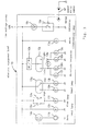
- Fig. 1 is a block diagram showing an electric system of an electric vehicle including an apparatus for preventing over-discharge of a battery according to the present invention.
- An electric system 1 of an electric vehicle includes: a running power source 2; a motor drive circuit 4 for supplying an AC power to each winding of a running motor 3; a DC-DC convertor 6 for receiving a power from the running power source 2 and supplying a low voltage power VR to low voltage loads 5; a low voltage secondary battery 7; a breaking means 8 for breaking the supply of a power to the low voltage loads 5; a main switch 9; a charger 10; and a charge interface circuit (charge I/F circuit) 11.
- the low voltage loads 5 include an operation control unit 12 and electric equipment loads 13.
- the running power source 2 includes a plurality (for example, five pieces) of secondary batteries, each having a specified rated output voltage (for example, 12 V), which are connected in series for supplying a high DC voltage (for example, 60 V).
- a three-phase ,brushless servo-motor is used as the running motor 3.
- the motor drive circuit 4 includes an invertor for converting a DC power supplied from the running power source 2 into an AC power and supplying the AC power to the running motor 3.
- the motor drive circuit 4 switches a plurality of switching elements constituting the invertor on the basis of a switching command signal 12a supplied from the operation control unit 12, to supply a power to each winding of the running motor 3 for rotating the running motor 3.
- the low voltage power VR is dependent from the running power source 2 in this embodiment, the switching command signal 12a outputted from the operation control unit 12 is transmitted to the motor drive circuit 4 side through a power separating type signal transmission circuit (not shown) such as a photocoupler.
- a switching regulator of an input-output isolating type is used as the DC-DC convertor 6.
- the DC-DC convertor 6 starts DC-DC conversion when a specified voltage is supplied to a starting control input terminal ST.
- reference characters HVI and HVG indicate input terminals of a high voltage power side
- VRO and VRG indicate output terminals of a low voltage power VR side.
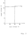
- Fig. 2 is a graph showing one example of an input/output characteristic of the DC-DC convertor.
- the DC-DC convertor 6 is intended to regulate an output voltage by monitoring the output voltage of the low voltage power VR and to control the switching condition on the high voltage side so that the output voltage is not excessively large or insufficient. Accordingly, even when the output voltage of the running power source 2 (input voltage of the DC-DC convertor) is reduced, for example, from 60 V to about 40 V, the output voltage of the low voltage power VR is regulated, for example, at 13.5 V.
- the DC-DC convertor 6 is so constructed that when the output voltage of the running power source 2 (input voltage of the DC-DC convertor) is reduced, for example, to 40 V or less, the output of the low voltage power VR is stopped.
- the maximum output voltage of the DC-DC convertor 6 is set to be slightly larger than an average power consumption of the low voltage loads 5.
- the low voltage battery 7 has a capacity smaller than that of one of the secondary batteries constituting the running power source 2 (for example, about 1/10 of the battery capacity of the running power source).
- the low voltage secondary battery 7 is charged by receiving the output voltage of the DC-DC convertor 6 through a counterflow preventive diode 14. It is to be noted that the counterflow preventive diode 14 may be provided in the DC-DC convertor 6.
- a power is supplied from the cathode side of the counterflow preventive diode 14 to the low voltage loads 5 through the breaking means 8.
- the underpower is supplied from the low voltage secondary battery 7 to the low voltage loads 5.
- the breaking means 8 is composed of a relay.
- the low voltage power VR outputted from the DC-DC convertor 6 is applied to an exciting winding 8a of the relay, and the supply/breaking of a power to the low voltage loads 5 is performed through a normally-open contact 8b of the relay.
- the main switch 9 is composed of a key switch and the like.
- a voltage for example, 12 V
- the DC-DC convertor 6 is operated to output the low voltage power VR when a specified voltage (for example, 12 V) is thus supplied to the starting control input terminal ST.
- the low voltage power VR is supplied to the operation control unit 12 as one of the low voltage loads 5 through the counterflow preventive diode 14 and the contact 8b of the relay in the breaking means 8, so that the electric vehicle 1 is turned in the operable state.
- a switch having a low withstand voltage can be used in this embodiment because a relatively low voltage is supplied to the starting control input terminal ST of the DC-DC converter 6 through a main switch 9 for starting the DC-DC converter 6.
- the charger 10 outputs a charging DC power VJ by voltage transformation and rectification of a commercial power.
- the charging DC power VJ is supplied to the running power source 2 through a running power source charging diode 16.
- the charger 10 includes a function of controlling the output voltage and the output current.
- the charger 10 certainly charges the running power source 2 and also prevents over-charge of the running power source 2 by checking the charging state of the running power source 2 through monitoring the output current and controlling the output voltage and output current on the basis of the charging state.
- the charge interface circuit 11 includes a simplified constant voltage circuit 17, an on-charge DC-DC convertor starting circuit 18, and a charging state information transmitting circuit 19.
- the simplified constant voltage circuit 17 outputs a DC voltage VK required for starting the DC-DC convertor 6.
- the on-charge DC-DC convertor starting circuit 18 is composed of a counterflow preventive diode.
- the starting DC voltage VK is supplied to the starting control input terminal ST of the DC-DC convertor 6 through the on-charge DC-DC convertor starting circuit (counterflow preventive diode). This allows the DC-DC convertor 6 to be started even when the main switch 9 is in the off-state, to thereby charge the low voltage secondary battery 7 by the output from the DC-DC convertor 6.
- the charging state information transmitting circuit 19 is composed of a power separating type signal transmitting circuit such as a photocoupler.
- a current is made to flow in a photodiode on the basis of the output voltage VK from the simplified constant voltage circuit 17, to turn on a phototransistor, thereby controlling a charging state information input terminal 12b of the operation control unit 12 at an L level.
- the operation control unit 12 stops the operation of the electric vehicle 1 in the charging state by stopping the operation control.
- the operation control unit 12 in a normal operating state checks the mechanically rotational position of a rotor of the running motor 3 on the basis of the output from a rotor angle sensor 3K; to determine an energizing timing to each winding of the running motor 3; and further it produces and outputs the switching command signal 12a subjected to pulse width modulation (PWM) in accordance with a throttle opening degree detected by a throttle opening, degree sensor 12T, to thereby adjust the output from the running motor 3.
- PWM pulse width modulation
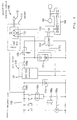
- Fig. 3 is a circuit diagram showing examples of electric equipment loads.
- Examples of the electric equipment loads include a horn 13b operated by a horn switch 13a; a tail lamp 13c; a stop lamp 13f connected in series to switches 13d, 13e closed in accordance with braking operation; a high beam head lamp 13h and a low beam head lamp 13i lit through a beam switch 13g; winker lamps 13l to 13p flashed by a winker timer 13k on the basis of operation of a winker switch 13j; a meter illuminating lamp 13q; and a light emitting diode 13s for indicating an over-speed, which is lit through a switch 13r closed when a vehicular speed detected through a speed meter cable SP is more than a specified value.
- the tail lamp 13c either of the head lamp 13h and 13i, and the meter illuminating lamp 13q are usually lit when the main switch 2 is operated to output the low voltage power VR and the low voltage power VR thus outputted is supplied through the breaking means 8 to the electric equipment loads 13.
- the winker lamps 13n and 13o on the right side are flashed and also the indicator lamp 13p for indicating the winker operation is flashed.
- a current is also supplied to the winker lamps 13l and 13m on the left side through the indicator lamp 13p; however, the winker lamps 13l and 13m are not lit because the indicator lamp 13p is small in power consumption (for example, 3.4 watt) and high in resistance and thereby a voltage generated across each of the winker lamps 13l and 13m (each power consumption: 10 watt) on the left side is low.
- the winker switch 13j is switched on the left side, the winker lamps 13l and 13m, and the indicator lamp 13p on the left side are flashed, while the winker lamps 13n and 13p on the right side are not lit.
- a starting power for example, a voltage equivalent to that of one of the secondary batteries
- the running power source 2 for example, a voltage equivalent to that of one of the secondary batteries
- the low voltage power VR is supplied to the exciting winding 8a of the relay constituting the breaking means 8, and the normally-open contact 8b of the relay is closed.
- the low voltage power VR is thus supplied to the operation control unit 12 and the electric equipment loads 13, thus turning the electric vehicle in the operable state.
- the battery capacity of the running power source 2 is reduced because the supply of a power to the low voltage loads 5 (operation control unit 12 and electric equipment loads 13) through the DC-DC convertor 6 is continued.
- a voltage to be supplied to the primary side (terminal HVI and HVG) of the DC-DC convertor 6 is reduced.
- the DC-DC convertor 6 stops the output of the low voltage power VR.
- the normally-open contact 8b of the relay constituting the breaking means 8 is thus turned in the open state, to thereby stop, the supply of a power from the low voltage secondary battery 7 to the low voltage loads 5.
- the stopping of the output of the low voltage power VR reduces the power consumption of the primary side of the DC-DC convertor 6, that is, the supply of a power from the running power source 2.
- Fig. 4 is a circuit diagram showing another example of the breaking means.
- a breaking means 20 shown in Fig. 4 uses semiconductor switching elements such as transistors in place of the relay.
- a base current is supplied to an NPN type transistor 22 through a base resistor 21, to turn on the NPN type transistor 22, and it also flows in a PNP type transistor 24 through a base resistor 23, to turn on the PNP type transistor 24, thus supplying a power to the low voltage loads 5.
- a phototransistor constituting a charging state information transmitting circuit 19 is turned on, the base-emitter of the NPN type transistor 22 is short-circuited, to turn off the transistors 22 and 24, thus stopping the supply of a power to the low voltage loads 5.
- the charging of the low voltage secondary battery 7 by the output of the low voltage power from the DC-DC convertor 6 can be effectively performed by stopping the supply of a power to the low voltage loads 5 in the charging state.
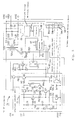
- Fig. 5 is a circuit diagram showing another example of the DC-DC convertor.
- a DC-DC convertor 60 shown in Fig. 5 contains the counterflow preventive diode 14 and includes an output terminal VRD connected to the counterflow preventive diode 14.
- the DC-DC convertor 60 includes a starting control unit 61, a power source portion 62, a convertor main body 63, and a voltage reduction detecting means 64.
- a starting power for example, 12 V
- a base current is supplied to a starting transistor (PNP type transistor) Q1 by way of an emitter-base, resistor R1 and capacitor C1 during a time constant set by the resistor R1 and capacitor C1.
- the starting transistor Q1 is turned on during the base current is supplied, and the base current is supplied to an NPN type transistor Q2 through a resistor R2.
- a diode D1 is provided for releasing charges of the capacitor C1 when the supply of the starting power is stopped.
- a constant voltage diode Z1 is of a type in which a breakdown voltage is, for example, about 9 V.
- a base current flows in a PNP type transistor Q3 through a base resistor R3, the constant voltage diode Z1 and the NPN type transistor Q2, and thereby the PNP type transistor Q3 is turned on.
- the PNP type transistor Q3 When the PNP type transistor Q3 is turned on, the NPN type transistor Q2 and PNP transistor Q3 are kept in the on-state even when the starting transistor Q1 is turned off because a base current is supplied from the collector side of the PNP type transistor Q3 to the NPN type transistor Q2 through a feedback resistor R4.
- a base current is supplied to an NPN type transistor Q4 through a base resistor R5 and thereby the NPN type transistor Q4 is turned on and is connected to a constant voltage diode Z2.
- the breakdown voltage of the constant voltage diode Z2 is set at, for example, about 6 V. Accordingly, after the PNP type transistor Q3 is turned on, the NPN type transistor Q2 and PNP type transistor Q3 are kept in the on-state even when a voltage supplied to the starting control input terminal ST is reduced, for example, to about 7 V.
- a base current flows in a NPN type transistor Q5 provided for stopping the starting operating, through a current limiting resistor R6, a constant voltage diode Z3 for detecting over-voltage upon starting control, and a counterflow preventive diode D2, and thereby the NPN type transistor Q5 is turned on, to short-circuit the base-emitter of the NPN type transistor Q2 provided for driving the starting operation, thereby preventing the drive of the starting operation.
- the PNP type transistor Q3 When the PNP type transistor Q3 is turned on, a base current flows through a base resistor R7 in an NPN type transistor Q6 provided for driving a high voltage power source, to thereby turn on the NPN type transistor Q6, and a base current flows in a PNP type transistor Q7 provided for turning on a high voltage power source, through the NPN type transistor Q6. As a result, the PNP type transistor Q7 is turned on, so that a high voltage power (for example, 60 V) of the running power source supplied to the terminal HV1 flows in the power source portion 62.
- a high voltage power for example, 60 V
- the power source portion 62 includes a simplified constant voltage circuit having a bleeder resistor R11, an NPN type transistor Q11, a resistor R12, and a constant voltage diode Z11; and a regulated power source circuit U11 using a three-terminal regulator IC.
- a high voltage (for example, 60 V) of the running power source is reduced by the bleeder resistor R11, and is adjusted into, for example, about 20 to 25 V in the simplified constant voltage circuit using the NPN type transistor Q11.
- the output voltage is further regulated, for example, into about 15 V in the regulated power source circuit U11.
- the output voltage thus regulated is supplied to a switching control portion 67.
- the convertor main body 63 includes a transformer T21; a field effect transistor Q21 for switching a power of the running power source supplied to a primary winding T21a of the transformer T21; a current detecting resistor R21; rectifying diodes D21, D22 for rectifying an AC voltage generated at a secondary winding T21b of the transformer T21; a choke coil L21, a smoothing capacitor C21; the counterflow preventive diode 14; an output voltage detecting circuit 65; an isolator 66; and the switching control portion 67.
- the switching control portion 67 When a regulated power (for example, about 15 V) is supplied from the power source portion 62, the switching control portion 67 outputs a switching command signal 67a subjected to specified pulse width modulation (PWM) at a predetermined repeated period (switching frequency).
- PWM pulse width modulation
- the PWM switching command signal 67a is supplied to a gate of the field effect transistor Q21 through a gate resistor R22.
- the field effect transistor Q21 switches, on the basis of the PWM switching command signal 67a, a current flowing the primary winding T21a of the transformer T21, to generate an AC voltage corresponding to the winding ratio of the transformer T21 at the secondary winding T21b of the transformer T21.
- the AC voltage generated at the secondary winding T21b is rectified by the rectifying diodes D21, D22, followed by smoothing by the choke coil L21 and the smoothing capacitor C21, to output a low voltage power VR (low voltage DC voltage) between output terminals VRO and VRG.
- the low voltage power VR is also outputted between the output terminals VRD and VRG through the counterflow preventive diode 14.
- the output voltage detecting circuit 65 detects the output voltage of the low voltage power VR, and produces a signal having a pulse width or pulse period depending on the detected output voltage, or a signal having a pulse width or pulse period depending on a difference (deviation) between a predetermined rated voltage and the output voltage.
- the pulse signal 65a outputted from the output voltage detecting circuit 65 is transmitted to the switching control portion 67 through the isolator (power separating type signal transmitting circuit) 66 using a photocoupler or the like.
- the switching control portion 67 performs a feedback control of the pulse width of the PWM switching command signal 67a so that the output voltage of the low voltage power VR is within a specified voltage (for example, 13.5 ⁇ 1.5 V) on the basis of the information on the output voltage supplied through the isolator 66 or a difference (deviation) between the output voltage and the predetermined rated voltage.
- a specified voltage for example, 13.5 ⁇ 1.5 V
- the switching control portion 67 monitors whether or not the field effect transistor Q21 is normally operated on the basis of the voltage generated at the end of the current detecting resistor R21; and also adjusts the pulse width of the PWM switching command signal 67a in accordance with the value of the switching current for adjusting a power supplied to the low voltage side through the transformer T21, and controls a current on the primary side not to be made excessively large.
- the voltage reduction detecting circuit 64 includes a current limiting resistor 64a, a constant voltage diode 64b, and a photodiode 64c of a photocoupler.
- a voltage of the low voltage power VR is reduced, for example, to 10 V or less, a current is not allowed to flow in the photodiode 64c and thereby a phototransistor 64d provided on the starting control portion 61 side is turned off.
- a capacitor 64f is started through a resistor 64e, and when the voltage of the capacitor 64f is increased to a specified value (about 1.3 V in this embodiment), a base current flows in the NPN type transistor Q5 provided for stopping the starting operation, by way of a resistor 64g and the counterflow preventive diode D3, and thereby the NPN type transistor Q5 is turned on, thus short-circuiting the base-emitter of the NPN type transistor Q2 for driving the starting operation.
- a specified value about 1.3 V in this embodiment
- the NPN type transistor Q2 for driving the starting control, PNP type transistor Q3, NPN type transistor Q6 for driving a high voltage power, and PNP type transistor Q7 for turning on a high voltage power are all turned off, to thereby stop the operation of the DC-DC convertor 60.
- Fig. 5 shows the configuration in which the starting operation of the starting control portion 61 is stopped on the basis of the reduction in the output voltage of the DC-DC convertor main body 63; however, the switching control portion 67 may have a function of stopping the operation of the DC-DC convertor 60. Specifically, even when the pulse width of the PWM switching command signal 67a is subjected to feedback control so that the output voltage of the low voltage power VR is set at a value in a specified range (for example, 13.5 ⁇ 1.5 V) on the basis of information on the output voltage supplied through the isolator or a difference (deviation) between the output voltage and the rated voltage, there may occur a state that the output voltage is out of the specified range is continued for a specified time.
- a specified range for example, 13.5 ⁇ 1.5 V
- the battery capacity of the running power source 2 is judged to be reduced, and a pulse signal (not shown) is outputted from the switching control portion 67 for allowing a base current to flow in the NPN type transistor Q5 provided for stopping the starting operation, thereby stopping the operation of the DC-DC convertor.
- a voltage supplied to the power source portion 62 through the PNP type transistor Q7 provided for turning on a high voltage power in the starting control unit 61 is monitored by a voltage monitoring circuit (not shown), and when the voltage is for example more than 50 V, the switching control is started; however, when the switching control is started and then a state that the voltage is less than 40 V is continued for a specified time, the output of the PWM switching command signal 67a is stopped, to thereby stop the operation of the DC-DC convertor 60.
- the counterflow preventive diode 14 shown in Figs. 1 and 5 is provided for preventing the detection of the output voltage of the DC-DC convertor from being obstructed by the supply of a voltage of the low voltage secondary battery 8 to the DC-DC convertor 5 side.
- the output voltage detecting circuit 65 in the convertor main body 63 may be so constructed that the output voltage of the low voltage power is detected on the basis of an DC voltage obtained by rectifying an AC voltage generated at the secondary winding T21b of the transformer T21 using a different rectifying circuit (not shown), to thereby eliminate the necessity of provision of the counterflow preventive diode 14 in a power supply passage to the low voltage loads 5.
- the DC-DC convertor 60 shown in Fig. 5 can be restarted from the inoperative state by turning off the main switch 9 and then turning on it again.
- the stopping of the operation of the DC-DC convertor 60 is intended to be performed for preventing the running power source 2 from being over-discharged by leaving the main switch 9 in the on-state, and accordingly the reduced battery capacity of the running power source 2 is desirable to be charged as early as possible.
- the DC-DC convertor 6 is easily re-started by turning on the main switch 9 again and the electric vehicle comes to be in the operable state, the driver often does not sufficiently recognize the fact that the battery capacity of the running power source 2 is reduced.
- the DC-DC convertor 6 may be so constructed as not to be started by turning on the main switch 9 again but to be started by operating a returning device composed of a switch or the like operated after opening a hide cover provided in a location different from an ordinary operating unit or in the operating unit.
- a low voltage power obtained by conversion from a high voltage power of a running power source composed of a secondary battery by a DC-DC convertor is supplied to an operation control unit and electric equipment loads such as a lamp and is also used to charge a low voltage secondary battery, in which the running power source and the low voltage secondary battery are prevented from being over-discharged even when a main switch is left in the on-state.
Landscapes
- Engineering & Computer Science (AREA)
- Power Engineering (AREA)
- Life Sciences & Earth Sciences (AREA)
- Sustainable Development (AREA)
- Sustainable Energy (AREA)
- Transportation (AREA)
- Mechanical Engineering (AREA)
- Electric Propulsion And Braking For Vehicles (AREA)
- Charge And Discharge Circuits For Batteries Or The Like (AREA)
Claims (2)
- Vorrichtung zum Verhindern einer Überladung einer für ein Elektrofahrzeug (1) verwendeten Batterie, umfassend:eine Fahrspannungsquelle (2) hoher Spannung, die von einer Mehrzahl von Sekundärbatterien gebildet ist;einen DC-DC-Wandler (6) zum Aufnehmen einer Leistung von der Fahrspannungsquelle (2) und Ausgeben einer Niedrigspannungsleistung, der dazu ausgelegt ist, die Ausgabe der Niedrigspannungsleistung zu stoppen, wenn die Ausgangsspannung der Niedrigspannungsleistung nicht in einem bestimmten Spannungsbereich gehalten werden kann;einen Niedrigspannungsverbraucher (5), der durch die von dem DC-DC-Wandler (6) ausgegebene Niedrigspannungsleistung betrieben wird;eine Niedrigspannungssekundärbatterie (7), die durch die Ausgangsspannung von dem DC-DC-Wandler (6) geladen wird und eine Leistung zu dem Niedrigspannurgsverbraucher (5) zuführt; undein Unterbrechungsmittel (8) zum Unterbrechen der Zufuhr einer Leistung von der Niedrigspannungssekundärbatterie (7) zu dem Niedrigspannungsverbraucher (5) auf der Basis eines Stoppens der Ausgabe der Niedrigspannungsleistung von dem DC-DC-Wandler (6).
- Vorrichtung zum Verhindern einer Überladung einer für ein Elektrofahrzeug (1) verwendeten Batterie nach Anspruch 1, wobei das Unterbrechungsmittel (8) ein Relais umfaßt, welches eine Erregerwicklung (8a), zu welcher die Ausgangsspannung von dem DC-DC-Wandler zugeführt wird, und einen normalerweise offenen Kontakt (8b) aufweist, über welchen die Zufuhr einer Leistung zu dem Niedrigspannungsverbraucher (5) gesteuert wird.
Applications Claiming Priority (3)
| Application Number | Priority Date | Filing Date | Title |
|---|---|---|---|
| JP147861/95 | 1995-06-14 | ||
| JP14786195A JP3491714B2 (ja) | 1995-06-14 | 1995-06-14 | 電動車の電池過放電防止装置 |
| JP14786195 | 1995-06-14 |
Publications (3)
| Publication Number | Publication Date |
|---|---|
| EP0750384A2 EP0750384A2 (de) | 1996-12-27 |
| EP0750384A3 EP0750384A3 (de) | 1997-06-04 |
| EP0750384B1 true EP0750384B1 (de) | 1999-09-15 |
Family
ID=15439915
Family Applications (1)
| Application Number | Title | Priority Date | Filing Date |
|---|---|---|---|
| EP96109524A Expired - Lifetime EP0750384B1 (de) | 1995-06-14 | 1996-06-13 | Vorrichtung zum Schutz vor Überentladung einer Batterie die für elektrisch getriebene Fahrzeuge verwendet wird |
Country Status (6)
| Country | Link |
|---|---|
| US (1) | US5793189A (de) |
| EP (1) | EP0750384B1 (de) |
| JP (1) | JP3491714B2 (de) |
| DE (1) | DE69604239T2 (de) |
| ES (1) | ES2138267T3 (de) |
| TW (1) | TW311740U (de) |
Cited By (1)
| Publication number | Priority date | Publication date | Assignee | Title |
|---|---|---|---|---|
| TWI416788B (zh) * | 2010-11-03 | 2013-11-21 | Ind Tech Res Inst | 燃料電池系統 |
Families Citing this family (71)
| Publication number | Priority date | Publication date | Assignee | Title |
|---|---|---|---|---|
| JP3330049B2 (ja) * | 1997-03-07 | 2002-09-30 | 本田技研工業株式会社 | 電気自動車の制御装置 |
| DE19754964A1 (de) * | 1997-12-11 | 1999-06-17 | Bayerische Motoren Werke Ag | Vorrichtung zur Energieversorgung eines Kraftfahrzeuges |
| US6222282B1 (en) * | 1998-03-19 | 2001-04-24 | Advanced Peripheral Technologies, Ltd. | Wheelchair using one or more DC to DC converters to power accessories |
| JP3450220B2 (ja) * | 1999-04-16 | 2003-09-22 | 三菱電機株式会社 | 車両用電源装置 |
| JP2001071834A (ja) * | 1999-09-03 | 2001-03-21 | Yazaki Corp | 車載用電源装置 |
| JP3552614B2 (ja) * | 1999-11-11 | 2004-08-11 | トヨタ自動車株式会社 | 電源回路 |
| US6630749B1 (en) * | 1999-11-29 | 2003-10-07 | Autonetworks Technologies, Ltd. | Automobile power source monitor |
| JP3381708B2 (ja) * | 2000-05-02 | 2003-03-04 | トヨタ自動車株式会社 | 車両、電源系制御装置、電源系を制御する方法および車両の始動時制御方法 |
| JP2002272180A (ja) * | 2001-03-15 | 2002-09-20 | Sumitomo Heavy Ind Ltd | 誘導電動機 |
| JP3776348B2 (ja) * | 2001-12-10 | 2006-05-17 | 本田技研工業株式会社 | 車両用電源装置 |
| DE10217235A1 (de) * | 2002-04-18 | 2003-10-30 | Philips Intellectual Property | Schaltungsanordnung zur Erzeugung von Gleichspannungen |
| US6909201B2 (en) * | 2003-01-06 | 2005-06-21 | General Motors Corporation | Dual voltage architecture for automotive electrical systems |
| US7389837B2 (en) * | 2003-10-20 | 2008-06-24 | General Motors Corporation | Electric power control system for a hybrid vehicle |
| FR2874659B1 (fr) * | 2004-08-27 | 2011-03-18 | Peugeot Citroen Automobiles Sa | Procede d'inhibition de la commande d'arret automatique du moteur thermique d'un vehicule en cas d'absence du conducteur |
| US8365852B2 (en) * | 2005-12-21 | 2013-02-05 | Ford Global Technologies, Llc | Power supply system and method for powering a vehicle |
| JP4284335B2 (ja) * | 2006-06-01 | 2009-06-24 | 株式会社竹内製作所 | 作業用車両 |
| US7973499B2 (en) * | 2006-06-01 | 2011-07-05 | Takeuchi Mfg. Co., Ltd. | Working vehicle |
| DE102006038127A1 (de) * | 2006-08-14 | 2008-02-21 | Braun Gmbh | Elektrokleingerät mit Ladezustandsanzeige |
| JP4254890B2 (ja) * | 2007-09-20 | 2009-04-15 | トヨタ自動車株式会社 | 車両の制御装置 |
| JP4758407B2 (ja) * | 2007-10-03 | 2011-08-31 | 本田技研工業株式会社 | 電気自動車 |
| US8018699B2 (en) * | 2007-10-26 | 2011-09-13 | Caterpillar Inc. | Over voltage protection for reduced level electrical signal interfaces |
| JP5446283B2 (ja) * | 2009-01-23 | 2014-03-19 | 日産自動車株式会社 | 車両用充電制御装置 |
| JP5292186B2 (ja) * | 2009-05-28 | 2013-09-18 | トヨタ自動車株式会社 | 電動車両の電源システム |
| WO2011036758A1 (ja) * | 2009-09-25 | 2011-03-31 | トヨタ自動車株式会社 | 車両の充電システムおよびそれを備える電動車両 |
| WO2011099116A1 (ja) | 2010-02-09 | 2011-08-18 | トヨタ自動車株式会社 | 電動車両の電源システムおよびその制御方法 |
| US20110262824A1 (en) * | 2010-04-23 | 2011-10-27 | Gm Global Technology Operations, Inc. | Apparatus for a 12v hybrid fuel cell vehicle |
| JP5484192B2 (ja) * | 2010-05-20 | 2014-05-07 | 本田技研工業株式会社 | 電動車両の始動制御装置 |
| US10128674B2 (en) | 2010-10-19 | 2018-11-13 | Larry Nelson | Apparatus and method for charging and discharging a multiple battery system |
| WO2012054617A1 (en) * | 2010-10-19 | 2012-04-26 | Larry Nelson | Apparatus and method for charging and discharging a dual battery system |
| US10017057B2 (en) | 2011-10-19 | 2018-07-10 | Larry Nelson | Apparatus and method for charging and discharging a dual battery system |
| DE102010061763B4 (de) | 2010-11-23 | 2024-09-12 | Robert Bosch Gmbh | Batterie |
| JP5659771B2 (ja) * | 2010-12-17 | 2015-01-28 | トヨタ自動車株式会社 | 車両および車両の制御方法 |
| WO2012084131A2 (de) | 2010-12-23 | 2012-06-28 | Volkswagen Aktiengesellschaft | Verfahren und vorrichtung zum laden einer niedervoltbatterie in einem elektrischen antriebssystem |
| DE102011012316B4 (de) | 2010-12-23 | 2022-04-21 | Volkswagen Ag | Verfahren und Vorrichtung zum Laden einer Niedervoltbatterie in einem elektrischen Antriebssystem |
| JP2012196069A (ja) * | 2011-03-17 | 2012-10-11 | Honda Motor Co Ltd | 充電システム |
| KR101229441B1 (ko) * | 2011-03-18 | 2013-02-06 | 주식회사 만도 | 배터리 충전 장치 |
| JP5682438B2 (ja) * | 2011-04-28 | 2015-03-11 | トヨタ自動車株式会社 | 車両用電源システム |
| US8816530B2 (en) | 2011-09-29 | 2014-08-26 | Ford Global Technologies, Llc | System and method for managing electrical loads in a vehicle |
| KR101329093B1 (ko) * | 2011-10-25 | 2013-11-14 | 현대로템 주식회사 | 철도차량용 배터리 방전 방지 장치 및 그 철도차량 |
| ITBO20120315A1 (it) * | 2012-06-07 | 2013-12-08 | Ferrari Spa | Impianto elettrico di potenza di un veicolo con propulsione elettrica |
| CN102745086B (zh) * | 2012-07-25 | 2015-06-17 | 江苏万得电动车研究所有限公司 | 一种用于电动汽车的低压控制系统 |
| FR2995736B1 (fr) * | 2012-09-20 | 2015-10-30 | Renault Sas | Systeme et procede d'alimentation pour un vehicule electrique |
| KR20140054796A (ko) * | 2012-10-29 | 2014-05-09 | 삼성전기주식회사 | 전원 공급 장치 및 전기 자동차의 전원 공급 장치 |
| JP2014131404A (ja) * | 2012-12-28 | 2014-07-10 | Suzuki Motor Corp | 車両用充電装置 |
| US20140253019A1 (en) * | 2013-03-06 | 2014-09-11 | Richtek Technology Corporation | Charger Circuit and Control Circuit and Control Method Thereof |
| US9566916B2 (en) * | 2013-03-11 | 2017-02-14 | Ford Global Technologies, Llc | Hybrid electric vehicle power-up sequencing with VVC test |
| CN103439897B (zh) * | 2013-08-27 | 2016-01-20 | 湖南中联重科智能技术有限公司 | 一种备用电池控制装置、系统、方法和工程机械 |
| US9575952B2 (en) | 2014-10-21 | 2017-02-21 | At&T Intellectual Property I, L.P. | Unsupervised topic modeling for short texts |
| DE102015000593A1 (de) * | 2015-01-16 | 2016-07-21 | Audi Ag | Hochspannungsbatterie für ein Kraftfahrzeug und Kraftfahrzeug |
| JP6149872B2 (ja) * | 2015-01-16 | 2017-06-21 | トヨタ自動車株式会社 | 蓄電システム |
| FR3035362B1 (fr) * | 2015-04-24 | 2023-11-24 | Valeo Systemes De Controle Moteur | Systeme pour vehicule automobile |
| JP6642124B2 (ja) * | 2016-03-04 | 2020-02-05 | 工機ホールディングス株式会社 | 電気機器 |
| IT201600112547A1 (it) * | 2016-11-08 | 2018-05-08 | Magneti Marelli Spa | "Apparato di gestione dell’energia fornita a un sistema di bassa tensione di un autoveicolo comprendente uno stadio di recupero dell’energia e relativo procedimento" |
| GB2559819B (en) * | 2017-02-15 | 2019-07-24 | Mahindra Electric Mobility Ltd | Methods and systems for energy management in vehicles |
| WO2019092103A2 (en) | 2017-11-08 | 2019-05-16 | Eaton Intelligent Power Limited | Power distribution unit and fuse management for an electric mobile application |
| US11368031B2 (en) * | 2017-11-08 | 2022-06-21 | Eaton Intelligent Power Limited | Power distribution and circuit protection for a mobile application having a high efficiency inverter |
| US11070049B2 (en) | 2017-11-08 | 2021-07-20 | Eaton Intelligent Power Limited | System, method, and apparatus for power distribution in an electric mobile application using a combined breaker and relay |
| CN108528242B (zh) * | 2018-03-29 | 2020-04-21 | 吉利汽车研究院(宁波)有限公司 | 中低压上下电控制方法、装置及电子设备 |
| JP2019205276A (ja) * | 2018-05-23 | 2019-11-28 | トヨタ自動車株式会社 | 電源装置 |
| DE102019104136B4 (de) * | 2019-02-19 | 2025-07-03 | HOPPECKE Systemtechnik GmbH | Anordnung für ein Bordnetz eines Schienenfahrzeuges |
| US11689010B2 (en) | 2019-02-22 | 2023-06-27 | Eaton Intelligent Power Limited | Coolant fitting promoting turbulent flow |
| RU190210U1 (ru) * | 2019-03-11 | 2019-06-24 | Филипп Николаевич НИКОЛЬСКИЙ | Электросистема автомобиля |
| JP7200902B2 (ja) | 2019-10-07 | 2023-01-10 | トヨタ自動車株式会社 | 電動車両の電源回路 |
| KR102824805B1 (ko) * | 2019-12-16 | 2025-06-25 | 현대자동차주식회사 | 차량 및 차량의 제어방법 |
| WO2021121654A1 (de) | 2019-12-18 | 2021-06-24 | Sew-Eurodrive Gmbh & Co. Kg | Verfahren zum betreiben eines elektrischen fahrzeuges und elektrisches fahrzeug |
| CN112271781A (zh) * | 2020-10-30 | 2021-01-26 | 东风商用车有限公司 | 一种车辆双电气系统能量均衡管理控制方法及装置 |
| CN112644333A (zh) * | 2020-12-02 | 2021-04-13 | 中车唐山机车车辆有限公司 | 轨道车辆及其电池控制系统 |
| JP7714900B2 (ja) * | 2021-04-13 | 2025-07-30 | トヨタ自動車株式会社 | サービスプラグ、車載電源装置、車両 |
| CN113258648B (zh) * | 2021-06-17 | 2021-12-07 | 浙江富特科技股份有限公司 | 一种车载dcdc变换器防输出侧电池电压丢失的电路 |
| CN116331059A (zh) * | 2023-04-20 | 2023-06-27 | 梅赛德斯-奔驰集团股份公司 | 电池连接器和车辆电池系统 |
| WO2025073062A1 (en) * | 2023-10-06 | 2025-04-10 | Transtech Innovations Inc. | Low voltage power unit |
Family Cites Families (9)
| Publication number | Priority date | Publication date | Assignee | Title |
|---|---|---|---|---|
| JPS603577A (ja) * | 1983-06-20 | 1985-01-09 | Seiko Epson Corp | 太陽電池時計 |
| US5200688A (en) * | 1991-05-31 | 1993-04-06 | Motorola, Inc. | Vehicular charger |
| JPH0630505A (ja) * | 1992-01-31 | 1994-02-04 | Fuji Electric Co Ltd | 電気自動車の電気システム |
| US5285862A (en) * | 1992-03-16 | 1994-02-15 | Toyota Jidosha Kabushiki Kaisha | Power supply system for hybrid vehicles |
| JP3039119B2 (ja) * | 1992-03-31 | 2000-05-08 | 日産自動車株式会社 | 車両用電源装置 |
| JPH0654410A (ja) * | 1992-06-05 | 1994-02-25 | Fuji Electric Co Ltd | 電気自動車の電気システム |
| JPH06133401A (ja) * | 1992-10-15 | 1994-05-13 | Yamaha Motor Co Ltd | 電動車両の電装品用電源装置 |
| JP3219524B2 (ja) * | 1993-01-19 | 2001-10-15 | 三洋電機株式会社 | 二次電池の過放電保護回路 |
| JP3195879B2 (ja) * | 1994-07-07 | 2001-08-06 | 株式会社日立製作所 | 電気車の制御装置及び電気車の制御方法 |
-
1995
- 1995-06-14 JP JP14786195A patent/JP3491714B2/ja not_active Expired - Fee Related
- 1995-10-30 TW TW085209592U patent/TW311740U/zh unknown
-
1996
- 1996-06-13 ES ES96109524T patent/ES2138267T3/es not_active Expired - Lifetime
- 1996-06-13 DE DE69604239T patent/DE69604239T2/de not_active Expired - Fee Related
- 1996-06-13 EP EP96109524A patent/EP0750384B1/de not_active Expired - Lifetime
- 1996-06-14 US US08/663,909 patent/US5793189A/en not_active Expired - Lifetime
Cited By (1)
| Publication number | Priority date | Publication date | Assignee | Title |
|---|---|---|---|---|
| TWI416788B (zh) * | 2010-11-03 | 2013-11-21 | Ind Tech Res Inst | 燃料電池系統 |
Also Published As
| Publication number | Publication date |
|---|---|
| TW311740U (en) | 1997-07-21 |
| DE69604239T2 (de) | 1999-12-30 |
| US5793189A (en) | 1998-08-11 |
| EP0750384A2 (de) | 1996-12-27 |
| EP0750384A3 (de) | 1997-06-04 |
| ES2138267T3 (es) | 2000-01-01 |
| JPH099402A (ja) | 1997-01-10 |
| DE69604239D1 (de) | 1999-10-21 |
| JP3491714B2 (ja) | 2004-01-26 |
Similar Documents
| Publication | Publication Date | Title |
|---|---|---|
| EP0750384B1 (de) | Vorrichtung zum Schutz vor Überentladung einer Batterie die für elektrisch getriebene Fahrzeuge verwendet wird | |
| US6657833B2 (en) | Relay welding detector and detecting method | |
| US6313546B1 (en) | Power supply assembly for a vehicle | |
| JP3676184B2 (ja) | 車両用電源装置 | |
| US5057763A (en) | High power supply for motor vehicle | |
| US6104160A (en) | Household power supply system using electric vehicle | |
| US5550445A (en) | Generator controller and controlling method for hybrid vehicle | |
| JP3327766B2 (ja) | バッテリアイソレータ | |
| EP1056181A2 (de) | Vorrichtung zur Diagnose elektrischer Stromversorgung während Strom durch die Stromversorgung zum Verbraucher geliefert wird | |
| JP2003509993A (ja) | 電力管理のためのインテリジェントスイッチ | |
| CN113002329A (zh) | 用于交通工具的可变电压充电系统和方法 | |
| JPH114506A (ja) | 車両発電装置 | |
| JP2001339803A (ja) | ハイブリッド電気自動車の充電装置 | |
| JP3448850B2 (ja) | ハイブリッド電気自動車の充電装置 | |
| EP1087496A2 (de) | Stromversorgungsgerät für ein Fahrzeug | |
| JP3632776B2 (ja) | 電動車両用充電装置 | |
| JPH0715807A (ja) | 電気自動車用電源装置 | |
| JPH08214403A (ja) | 電気自動車の駆動制御装置 | |
| JP3707650B2 (ja) | 電気自動車用電源装置 | |
| JP2006304390A (ja) | ハイブリッド車両用電源装置 | |
| EP0740396B1 (de) | Spannungsregler eines Fahrzeuggenerators | |
| JPH03124201A (ja) | 電気自動車用補機電池充電装置 | |
| KR100534795B1 (ko) | 하이브리드 전기 자동차의 컨버터 구동장치 및 그 제어방법 | |
| JP2004229477A (ja) | 車両用電源制御装置 | |
| KR100273517B1 (ko) | 전기자동차의 배터리 충전중 시동 제어방법 |
Legal Events
| Date | Code | Title | Description |
|---|---|---|---|
| PUAI | Public reference made under article 153(3) epc to a published international application that has entered the european phase |
Free format text: ORIGINAL CODE: 0009012 |
|
| AK | Designated contracting states |
Kind code of ref document: A2 Designated state(s): DE ES FR IT |
|
| PUAL | Search report despatched |
Free format text: ORIGINAL CODE: 0009013 |
|
| AK | Designated contracting states |
Kind code of ref document: A3 Designated state(s): DE ES FR IT |
|
| 17P | Request for examination filed |
Effective date: 19970722 |
|
| GRAG | Despatch of communication of intention to grant |
Free format text: ORIGINAL CODE: EPIDOS AGRA |
|
| GRAG | Despatch of communication of intention to grant |
Free format text: ORIGINAL CODE: EPIDOS AGRA |
|
| GRAH | Despatch of communication of intention to grant a patent |
Free format text: ORIGINAL CODE: EPIDOS IGRA |
|
| 17Q | First examination report despatched |
Effective date: 19981111 |
|
| GRAH | Despatch of communication of intention to grant a patent |
Free format text: ORIGINAL CODE: EPIDOS IGRA |
|
| GRAA | (expected) grant |
Free format text: ORIGINAL CODE: 0009210 |
|
| AK | Designated contracting states |
Kind code of ref document: B1 Designated state(s): DE ES FR IT |
|
| ITF | It: translation for a ep patent filed | ||
| REF | Corresponds to: |
Ref document number: 69604239 Country of ref document: DE Date of ref document: 19991021 |
|
| ET | Fr: translation filed | ||
| REG | Reference to a national code |
Ref country code: ES Ref legal event code: FG2A Ref document number: 2138267 Country of ref document: ES Kind code of ref document: T3 |
|
| PLBE | No opposition filed within time limit |
Free format text: ORIGINAL CODE: 0009261 |
|
| STAA | Information on the status of an ep patent application or granted ep patent |
Free format text: STATUS: NO OPPOSITION FILED WITHIN TIME LIMIT |
|
| 26N | No opposition filed | ||
| PGFP | Annual fee paid to national office [announced via postgrant information from national office to epo] |
Ref country code: ES Payment date: 20030619 Year of fee payment: 8 |
|
| PG25 | Lapsed in a contracting state [announced via postgrant information from national office to epo] |
Ref country code: ES Free format text: LAPSE BECAUSE OF NON-PAYMENT OF DUE FEES Effective date: 20040614 |
|
| PGFP | Annual fee paid to national office [announced via postgrant information from national office to epo] |
Ref country code: FR Payment date: 20050608 Year of fee payment: 10 |
|
| REG | Reference to a national code |
Ref country code: ES Ref legal event code: FD2A Effective date: 20040614 |
|
| REG | Reference to a national code |
Ref country code: FR Ref legal event code: ST Effective date: 20070228 |
|
| PGFP | Annual fee paid to national office [announced via postgrant information from national office to epo] |
Ref country code: DE Payment date: 20070607 Year of fee payment: 12 |
|
| PGFP | Annual fee paid to national office [announced via postgrant information from national office to epo] |
Ref country code: IT Payment date: 20070612 Year of fee payment: 12 |
|
| PG25 | Lapsed in a contracting state [announced via postgrant information from national office to epo] |
Ref country code: FR Free format text: LAPSE BECAUSE OF NON-PAYMENT OF DUE FEES Effective date: 20060630 |
|
| PG25 | Lapsed in a contracting state [announced via postgrant information from national office to epo] |
Ref country code: DE Free format text: LAPSE BECAUSE OF NON-PAYMENT OF DUE FEES Effective date: 20090101 |
|
| PG25 | Lapsed in a contracting state [announced via postgrant information from national office to epo] |
Ref country code: IT Free format text: LAPSE BECAUSE OF NON-PAYMENT OF DUE FEES Effective date: 20080613 |