EP0749369B1 - Groupe imprimant pour rotative a bobines pour impression en couleurs - Google Patents
Groupe imprimant pour rotative a bobines pour impression en couleurs Download PDFInfo
- Publication number
- EP0749369B1 EP0749369B1 EP95911209A EP95911209A EP0749369B1 EP 0749369 B1 EP0749369 B1 EP 0749369B1 EP 95911209 A EP95911209 A EP 95911209A EP 95911209 A EP95911209 A EP 95911209A EP 0749369 B1 EP0749369 B1 EP 0749369B1
- Authority
- EP
- European Patent Office
- Prior art keywords
- printing
- group according
- printing group
- printing unit
- unit
- Prior art date
- Legal status (The legal status is an assumption and is not a legal conclusion. Google has not performed a legal analysis and makes no representation as to the accuracy of the status listed.)
- Expired - Lifetime
Links
- 238000007639 printing Methods 0.000 title claims abstract description 152
- 239000007921 spray Substances 0.000 claims description 11
- 238000007774 anilox coating Methods 0.000 claims description 9
- 230000008878 coupling Effects 0.000 claims description 7
- 238000010168 coupling process Methods 0.000 claims description 7
- 238000005859 coupling reaction Methods 0.000 claims description 7
- 238000013016 damping Methods 0.000 claims 7
- 241000252254 Catostomidae Species 0.000 claims 1
- 239000000969 carrier Substances 0.000 description 4
- 238000000034 method Methods 0.000 description 4
- 238000007645 offset printing Methods 0.000 description 4
- 239000003795 chemical substances by application Substances 0.000 description 3
- 125000006850 spacer group Chemical group 0.000 description 3
- 238000010276 construction Methods 0.000 description 2
- 230000000694 effects Effects 0.000 description 2
- 238000005538 encapsulation Methods 0.000 description 2
- 238000012423 maintenance Methods 0.000 description 2
- 238000005507 spraying Methods 0.000 description 2
- 239000000725 suspension Substances 0.000 description 2
- 238000004887 air purification Methods 0.000 description 1
- 238000004140 cleaning Methods 0.000 description 1
- 238000006073 displacement reaction Methods 0.000 description 1
- 238000000605 extraction Methods 0.000 description 1
- 238000003780 insertion Methods 0.000 description 1
- 230000037431 insertion Effects 0.000 description 1
- 238000009413 insulation Methods 0.000 description 1
- 238000007644 letterpress printing Methods 0.000 description 1
- 239000003973 paint Substances 0.000 description 1
- 238000011084 recovery Methods 0.000 description 1
- 239000002699 waste material Substances 0.000 description 1
Images


Classifications
-
- B—PERFORMING OPERATIONS; TRANSPORTING
- B41—PRINTING; LINING MACHINES; TYPEWRITERS; STAMPS
- B41F—PRINTING MACHINES OR PRESSES
- B41F13/00—Common details of rotary presses or machines
- B41F13/0024—Frames
-
- B—PERFORMING OPERATIONS; TRANSPORTING
- B41—PRINTING; LINING MACHINES; TYPEWRITERS; STAMPS
- B41F—PRINTING MACHINES OR PRESSES
- B41F13/00—Common details of rotary presses or machines
- B41F13/008—Mechanical features of drives, e.g. gears, clutches
-
- B—PERFORMING OPERATIONS; TRANSPORTING
- B41—PRINTING; LINING MACHINES; TYPEWRITERS; STAMPS
- B41F—PRINTING MACHINES OR PRESSES
- B41F27/00—Devices for attaching printing elements or formes to supports
- B41F27/12—Devices for attaching printing elements or formes to supports for attaching flexible printing formes
- B41F27/1206—Feeding to or removing from the forme cylinder
-
- B—PERFORMING OPERATIONS; TRANSPORTING
- B41—PRINTING; LINING MACHINES; TYPEWRITERS; STAMPS
- B41F—PRINTING MACHINES OR PRESSES
- B41F7/00—Rotary lithographic machines
- B41F7/02—Rotary lithographic machines for offset printing
- B41F7/12—Rotary lithographic machines for offset printing using two cylinders one of which serves two functions, e.g. as a transfer and impression cylinder in perfecting machines
-
- B—PERFORMING OPERATIONS; TRANSPORTING
- B41—PRINTING; LINING MACHINES; TYPEWRITERS; STAMPS
- B41P—INDEXING SCHEME RELATING TO PRINTING, LINING MACHINES, TYPEWRITERS, AND TO STAMPS
- B41P2213/00—Arrangements for actuating or driving printing presses; Auxiliary devices or processes
- B41P2213/70—Driving devices associated with particular installations or situations
- B41P2213/73—Driving devices for multicolour presses
- B41P2213/734—Driving devices for multicolour presses each printing unit being driven by its own electric motor, i.e. electric shaft
-
- B—PERFORMING OPERATIONS; TRANSPORTING
- B41—PRINTING; LINING MACHINES; TYPEWRITERS; STAMPS
- B41P—INDEXING SCHEME RELATING TO PRINTING, LINING MACHINES, TYPEWRITERS, AND TO STAMPS
- B41P2217/00—Printing machines of special types or for particular purposes
- B41P2217/10—Printing machines of special types or for particular purposes characterised by their constructional features
- B41P2217/11—Machines with modular units, i.e. with units exchangeable as a whole
Definitions
- the invention relates to a printing unit for a multi-color web-fed rotary printing press for face and back printing, in accordance with the preamble of claim 1.
- a H-shaped printing unit consists of two U-shaped printing units arranged in mirror image to each other, which is also referred to as a U-printing unit and each has four bridges.
- a disadvantage of these pressure units arranged one above the other in tower construction is that, for.
- the paper web to be printed has to travel a relatively long way between the printing points, which can lead to registration problems.
- the above-mentioned printing units have a large overall height, so that the operating personnel in at least two levels of different heights must operate.
- the inking units assigned to the printing units have one color flow direction from top to bottom and one color flow direction from bottom to top according to the mirror-image arrangement of the individual U-shaped printing units, which can lead to different color behavior.
- the invention has for its object to provide a printing unit for a multi-color web-fed rotary printing press for face and back printing in a low overall height with the same performance parameters compared to the prior art of Tecknik.
- the printing press according to the invention has a low overall height and thus less weight, which among other things also reduces the costs for the machine foundation.
- the color flow in each printing unit always has the same direction, so that the same color behavior is achieved in all printing units.
- the costs for a possible encapsulation of the machine are reduced due to the lower overall height. Such encapsulation can be important for reasons of sound insulation or for heat recovery in connection with air purification.
- printing units of the printing press according to the invention can also be used as an additional printing unit or as a printing unit for a flying printing plate change (imprinter).
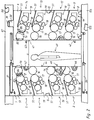
- Upper carrier 87, 88 and lower, horizontally running lower carrier 104, 105 of a multi-color web-fed rotary printing press accommodate a plurality of printing units arranged one above the other in a left frame part 1, 6 in a carrier-fixed manner.
- the printing unit units are each designated 2, 3, 4 and 5 as left printing units.
- Each printing unit 2 to 5 and 11 to 14 each consists of a blanket cylinder 16 which cooperates with a forme cylinder 17.
- the forme cylinder 17 receives dampening solution via an overall dampening unit designated 18 and ink over an overall fed with 19 designated inking unit.
- the inking unit 19 can, for. B. consist of an ink pan 21 with an inking roller 22 (Fig. 8), the inking roller 22 transfers its printing ink by means of inking rollers 23, 24 to the forme cylinder 17. Instead of two inking rollers 23, 24 of the same size, only a smaller or larger inking roller can be used. Instead of an ink pan 21 and an ink roller 22 z. B. also a chamber doctor blade can be used in connection with an anilox roller (anilox roller). However, a conventional inking unit can also be used (Fig. 13).
- Each dampening unit 18 can be designed as a spray dampening unit, which consists of a known spray device 26, for. B. there is a bar with spray nozzles, which direct their spray jets onto a dampening roller 27. This dampening solution application roller 27 is connected to the forme cylinder 17.
- the between the carriers 87, 88; 104, 105 stationarily arranged printing units 2 to 5 and the between the carriers 87, 88; 104, 105 in displaceable frame parts 9, 10 one above the other printing units 11 to 14 are each arranged with their blanket cylinder 16 directed towards each other, so that a paper web 28 or 29 can be printed on both sides.
- the possible points of contact of the blanket cylinders 16 with one another are designated 31, 32, 33, 34 (FIG. 1), so that the printing units 2 with 11, 3 with 12, 4 with 13 and 5 with 14 each form a bridge printing unit or a printing unit in bridge construction, which are arranged vertically divisible and horizontally displaceable at their printing point 31 to 34.
- the displaceable frame 9, 10 is by means of two double-acting cylinders 36, 37, z. B. hydraulic cylinder, actuated.
- the working cylinder 36, 37 is mounted fixed to the side frame and the end of the piston rod remote from the cylinder is articulated to the displaceable frame 9, 10, in each case on its top and bottom.
- the frame 9, 10 in each case has a guide bar 38 on its upper side, which is guided in a groove 39 located in the carriers 87, 88 and open at the bottom.
- the flanks of the guide bar 38 can have recesses for receiving bearing balls which support the guide bar 38 against the side walls of the groove 39 located in the carriers 87, 88.
- the frame 9 and 10 In order to achieve a high degree of accuracy when retracting the displaceable frame 9 and 10 from the rest position (FIG. 2) into the working position (FIG. 1), the frame 9 and 10 has a plurality of pins 42 protruding beyond the closing edge 41 on its vertical closing edge 41, 43, the blind holes 46 located in a vertically running closing edge 44 of the side frame 1, 47 intervene.
- the displaceable frame 9 and 10 In the working position (FIG. 1), the displaceable frame 9 and 10 is secured against unintentional displacement by means of a mechanically acting locking device, designated overall by 48.
- the locking device 48 consists of a frame-mounted threaded bushing, which forms a positive connection when the frame 9, 10 is closed with a threaded spindle mounted on the support. The threaded spindle is moved in the direction of the left frame part 1, 6 by means of a motor-driven threaded sleeve.
- This pressure plate changing device 51 consists of two linear guides 52 (only one shown in FIG. 8) which are fixed to the frame at a distance of at least one forme cylinder width and on which both ends of a gripper bar 53 are guided.
- the gripper bar 53 extends in the axis-parallel direction to the forme cylinder 17 and carries a number of suction cups 54, by means of which a pressure plate 57 located in a waiting position on support rails 56 fixed to the frame on both sides (only one shown in FIG.
- the linear guides 52 can be designed as threaded spindles on which the gripper bar 53 is moved by means of threaded sleeves which are rotated by an electric motor.
- a parallel guide 63 is provided on each frame 1, 6 or frame 9, 10 and has stud bolts 64 which are positively attached on both sides to the housing of the spray device 26 and which run to the forme cylinder 17 in the axis-parallel direction.
- the stud bolts 64 are each provided on the circumference with a one-sided flattening 66 to prevent rotation, which slides on a support surface 67 of the parallel guide 63, so that the spray device 26 can be pulled out by means of a handle 68.
- the spraying device 26 can be locked in its working position (shown in FIG.
- each stud bolt 64 engaging in a recess 69 in the support surface 67 and each stud bolt 64 being held in this working position by means of a clamping device 71 consisting of a rack and pinion drive .
- the rack which can be moved by means of a pinion, presses against the stud 64.
- the spray device 26 is unlocked for the purpose of its removal by the rack of the clamping device 71 being retracted, so that the stud 64 is ejected from the recess 69 into the recess 69 by means of a spring-loaded ejector 72
- Level of the support surface 67 of the parallel guide 63 for removal can be raised (not shown in Figs. 1 and 2).
- a second left frame part 6 and a second right sliding frame part 10 is required for the function of the printing unit, as well as second working cylinder for moving the frame 9, 10 and associated locking devices and the like. More.
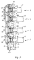
- the drive of the individual bridge printing units 2, 11; 3, 12; 4, 13; 5, 14 takes place via a standing shaft 73, which vertically extends from the main drive shaft of the printing press, of the forme cylinders 17, arranged one above the other in a vertical plane, of the stationary printing units 2, 3, 4, 5.
- Each printing unit 2, 3, 4, 5 is above the axle 74 of the in the frame 1, 6 mounted forme cylinder 17 by means of a z. B. electromagnetic clutch 76 separable from the standing shaft 73.
- the standing shaft 73 is formed at least in the region of the periphery of a ring gear 77 connected to each clutch 76 as a splined shaft, so that one of two pinions arranged on the standing shaft 73 in a form-fitting manner and belonging to the same ring gear 77 of each printing unit 2, 3, 4, 5 78, 79 with the ring gear 77 is engaged.
- the ring gear 77 with the pinion 78 each form a pair of bevel gears that are in engagement with one another.
- both are on the standing shaft 73 arranged pinions 78, 79 displaced in the vertical direction by means of a bow-shaped spacer 81, so that alternatively the pinion 79 comes into engagement with the ring gear 77.
- the respective spacer 81 can be actuated manually via a handle 82 or via known electrical, hydraulic or pneumatic actuating means.
- a spur gear 83 is also wedged, which per bridge pressure unit 2, 11; 3, 12; 4, 13 or 5, 14 also engages with the non-illustrated axle journals of the blanket cylinders 16 and the second forme cylinder 17, spur gears 84, 85, 86 which are positively connected (shown in FIG. 2 only with printing units 5 and 14).
- the spur gears 84, 85 only engage with one another when the printing press is in the working position.
- the respective dampening unit 18 and the respective inking unit 19 can be driven both by friction with the forme cylinder 17 and by means of a motor-driven individual drive of the inking roller 22 and of the dampening agent application roller 27 or by means of known gearwheels.
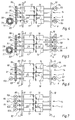
- a drive for a bridge printing unit consisting of the printing units 5 and 14 (FIG. 4) there is a difference compared to the above-mentioned drive (FIG. 3) in that a coupling 89, 92 already exists between the forme cylinders 17 and the spur gears 86, 83 and a clutch 90, 91 is already arranged between the blanket cylinders 16 and the spur gears 85, 84.
- Each bridge printing unit 2, 11; 3, 12; 4, 13 or 5, 14 can be equipped with this drive, so that, for. B.
- the forme cylinder 17 per bridge printing unit 5, 14 can be switched off (in Fig. 5, the forme cylinder 17 of the printing unit 14 is uncoupled), so that the respective uncoupled forme cylinder 17 can be provided with new printing plates during operation of the printing machine (imprinter).
- the blanket cylinder 16 assumes the function of an impression cylinder.
- the axle journal of the forme cylinder 17 on the side of the second displaceable frame 10 is provided with an auxiliary drive motor 93 which, after reaching the required speed by means of a clutch 94, from the forme cylinder 17 is separable, the forme cylinder 17 of the printing unit 14 being able to be connected to the spur gear 86 again via the coupling 89 (FIG. 5).
- a clutch 92 for the purpose of exchanging the printing plates.
- an auxiliary drive motor 96 is then provided on the left frame 6, which can be separated from the forme cylinder 17 via a coupling 97.
- the auxiliary drive motors 98, 99 can be separated from the blanket cylinders 16 by means of couplings 101, 102.
- each bridge printing unit 2, 11; 3, 12; 4, 13 or 5, 14 can each be provided with separate drive motors 106, 107, 108, 109 which can be uncoupled (FIG. 7).
- the axes of rotation 111, 112 of blanket and form cylinders 16, 17 of each printing unit 2 to 5 and 11 to 14 are each traversed by an imaginary straight line, which each represents a plane 114 or 110 and which each have an angle alpha in the range of zero is arranged up to ⁇ 45 ° to a horizontal 113.
- An axis of rotation 116 of the ink roller 22 can also be included in this plane 114 (FIG. 10).
- a height h of a printing unit 2, 3, 4, 5, 11, 12, 13 or 14 refers to twice to 3.75 times a forme cylinder 17 in the "Berlin format" (Fig. 12).
- the diameter of a forme cylinder 17 in the "Berlin format" is approximately 300 millimeters.
- FIG. 11 A known printing press, a so-called eight-high in an H shape, is shown in FIG. 11 (MAN-Roland) and consists of eight printing units, with two printing units in each case being combined in a U-shaped printing unit and being put together in mirror image to form an H printing unit are.
- type H - pressure unit on H - pressure unit the called aft tower formed.
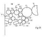
- a printing unit 118 with a conventional inking unit 117 and a modified dampening unit 119 is shown, which can be used instead of the printing units 2 to 5 and 11 to 14 with the dampening units 18 and the short inking units 19.
- the conventional inking unit 118 can consist of an ink fountain 112 with an ink duct 122 and a film roller 123, to which two ink transfer rollers 124 are excluded, to which ink rubbing cylinders 126 are interposed.
- the latter of the two ink rubbing cylinders 126 is connected to the form cylinder 17 via two ink application rollers 127 arranged parallel to one another.
- Said dampening unit 119 can consist of a spray dampening unit 128 with a dampening cylinder 129, the dampening cylinder 129 being connected via two dampening agent transfer rollers 133, 134 to a dampening unit application roller 132 which bears against the forme cylinder 17.
- the printing unit according to the invention can be used in particular in the following printing processes: for conventional offset printing and for anilox offset printing, for indirect letterpress printing and for waterless offset printing.
Landscapes
- Engineering & Computer Science (AREA)
- Mechanical Engineering (AREA)
- Rotary Presses (AREA)
Abstract
Claims (24)
- Groupe imprimant pour impression en couleurs recto et verso pour une rotative à bobines, dans laquelle deux unités d'impression sont conçues selon un agencement « en pont » sous la forme d'unités en pont avec chacune deux dispositifs d'encrage, chacune deux cylindres porte-forme imprimante et chacune deux cylindres porte-blanchet, les cylindres porte-blanchet étant tournés l'un vers l'autre et plusieurs unités en pont étant superposées, caractérisé en ce que les unités en pont superposées (2, 11 ; 3, 12 ; 4, 13 ; 5, 14) peuvent être divisées en deux parties (9 ; 1 ; 10), en une partie gauche de bâti (1 ; 6) pour recevoir des unités d'impression de gauche (2 à 5) ainsi qu'en une partie droite de bâti (9 ; 10) pour recevoir des unités d'impression de droite (11 à 14), et en ce que les deux parties de bâti (1, 6 ; 9 ; 10) peuvent être amenées à une distance horizontale (a) l'une par rapport à l'autre.
- Groupe imprimant selon la revendication 1, caractérisé en ce qu'une partie de bâti (1 ; 6) est montée solidaire des supports (104 ; 105).
- Groupe imprimant selon les revendications 1 et 2, caractérisé en ce que les deux parties de bâti (1, 6 ; 9, 10) peuvent être verrouillées (48) en position de fonctionnement.
- Groupe imprimant selon les revendications 1 à 3, caractérisé en ce que le dispositif d'encrage (19) de chaque unité d'impression (2 à 5 ; 11 à 14) est conçu sous la forme d'un dispositif d'encrage court anilox (19).
- Groupe imprimant selon la revendication 4, caractérisé en ce que le dispositif d'encrage court anilox (19) est au moins constitué d'un rouleau anilox (22) avec une racle à chambre qui lui est associée ainsi qu'au moins un rouleau applicateur d'encre (23 ; 24) associé au rouleau anilox (22) ainsi qu'un bac d'encre (21) disposé sous le rouleau anilox (22).
- Groupe imprimant selon les revendications 1 à 5, caractérisé en ce qu'un dispositif de mouillage (18) peut être associé à chaque unité d'impression (2 à 5 ; 11 à 14).
- Groupe imprimant selon la revendication 6, caractérisé en ce que le dispositif de mouillage (18) est constitué d'un dispositif d'humectation (27) associé à un dispositif de pulvérisation (26).
- Groupe imprimant selon la revendication 1, caractérisé en ce qu'un dispositif de changement de plaque d'impression (51) est associé à chaque cylindre porte-forme imprimante (17) de l'unité d'impression (2 à 5 ; 11 à 14).
- Groupe imprimant selon la revendication 8, caractérisé en ce que le dispositif de changement de plaque d'impression (51) contient deux guides linéaires (52) solidaires des bâtis latéraux pour recevoir une barre preneuse (53) qui peut se déplacer parallèlement à l'axe du cylindre porte-forme imprimante (17), qui comporte des moyens d'aspiration (54) et qui est destinée à amener les plaques d'impression (57).
- Groupe imprimant selon la revendication 1, caractérisé en ce que le cylindre porte-forme imprimante (17) de chaque unité d'impression (2 à 5 ; 11 à 14) peut être occulté séparément conjointement avec son dispositif d'encrage (19) et son dispositif de mouillage (18).
- Groupe imprimant selon la revendication 10, caractérisé en ce que le dispositif de pulvérisation (26) du dispositif de mouillage (18) peut être séparé du rouleau applicateur d'agent mouillant (27) au moyen de deux guidages parallèles (63) solidaires du bâti.
- Groupe imprimant selon les revendications 1 à 11, caractérisé en ce que chaque unité d'impression (2 à 5 ; 11 à 14) possède un encombrement en hauteur (h) compris entre deux fois et quatre fois le diamètre d'un cylindre porte-forme imprimante (17).
- Groupe imprimant selon la revendication 12, caractérisé en ce que le diamètre du cylindre porte-forme imprimante (17) se rapporte au « format berlinois ».
- Groupe imprimant selon les revendications 1 à 13, caractérisé en ce qu'au moins une unité d'impression (11, 12, 13, 14) par unité en pont (2, 11 ; 3, 12 ; 4, 13 ; 5, 14) peut se déplacer horizontalement.
- Groupe inprimant selon les revendications 1 et 6 à 14, caractérisé en ce que le dispositif d'encrage (117) de chaque unité d'impression (2 à 5 ; 11 à 14) est conçu sous la forme d'un dispositif d'encrage classique (117).
- Groupe imprimant selon la revendication 10, caractérisé en ce qu'un moyen d'accouplement (89 à 92) est implanté entre chaque cylindre (16 ; 17) et le moyen d'entraînement (83 à 86 ; 73 ; 103 ; 106 à 109) de chaque unité d'impression (2 à 5 ; 11 à 14).
- Groupe imprimant selon les revendications 10 et 16, caractérisé en ce que l'entraînement (83 à 86) de chaque unité d'impression (2 à 5 ; 11 à 14) s'effectue par l'intermédiaire d'un arbre vertical (73).
- Groupe imprimant selon les revendications 10 et 16, caractérisé en ce que l'entraînement (83 à 86) de chaque unité d'impression (2 à 5 ; 11 à 14) s'effectue par l'intermédiaire d'un moteur principal (103).
- Groupe imprimant selon les revendications 10 et 16, caractérisé en ce que le moyen d'entraînement de chaque cylindre (16 ; 17) de chacune des unités d'impression (2 à 5 ; 11 à 14) est conçu sous la forme d'un moyen d'entraînement individuel (106 à 109).
- Groupe imprimant selon les revendications 10 et 16 à 18, caractérisé en ce qu'à titre supplémentaire les cylindres (16 ; 17) de chaque unité d'impression (2 à 5 ; 11 à 14) peuvent être reliés à un moteur d'entraînement auxiliaire accouplable (93 ; 96 ; 98 ; 99).
- Groupe imprimant selon les revendications 1 à 20, caractérisé en ce que les axes de rotation (111, 112) des cylindres porte-blanchet et porte-forme imprimante (16, 17) de chaque unité d'impression (2 à 5 ; 11 à 14) sont disposés dans un plan (110 ; 114) qui s'étend selon un angle (± α) par rapport à l'horizontale (113).
- Groupe imprimant selon la revendication 21, caractérisé en ce que l'angle (α) est compris entre 0° et 45°.
- Groupe imprimant selon les revendications 1 et 6 à 22, caractérisé en ce que le dispositif d'encrage (118) de chaque unité d'impression (117) est conçu sous la forme d'un dispositif d'encrage classique (118).
- Groupe inprimant selon les revendications 1 à 23, caractérisé en ce que dans chaque bâti latéral (1, 6) est disposé un châssis (9 ; 10) qui peut se déplacer sur des galets (7 ; 8) et qui abrite les unités d'impression (11, 12, 13, 14) à déplacer.
Applications Claiming Priority (3)
| Application Number | Priority Date | Filing Date | Title |
|---|---|---|---|
| DE4408025A DE4408025A1 (de) | 1994-03-10 | 1994-03-10 | Druckwerk für eine Mehrfarbenrollenrotationsdruckmaschine |
| DE4408025 | 1994-03-10 | ||
| PCT/DE1995/000303 WO1995024314A1 (fr) | 1994-03-10 | 1995-03-07 | Groupe imprimant pour rotative a bobines pour impression en couleurs |
Publications (2)
| Publication Number | Publication Date |
|---|---|
| EP0749369A1 EP0749369A1 (fr) | 1996-12-27 |
| EP0749369B1 true EP0749369B1 (fr) | 1997-11-12 |
Family
ID=6512377
Family Applications (1)
| Application Number | Title | Priority Date | Filing Date |
|---|---|---|---|
| EP95911209A Expired - Lifetime EP0749369B1 (fr) | 1994-03-10 | 1995-03-07 | Groupe imprimant pour rotative a bobines pour impression en couleurs |
Country Status (8)
| Country | Link |
|---|---|
| US (1) | US5782182A (fr) |
| EP (1) | EP0749369B1 (fr) |
| JP (1) | JP3399535B2 (fr) |
| CN (1) | CN1081986C (fr) |
| BR (1) | BR9507037A (fr) |
| DE (2) | DE4408025A1 (fr) |
| RU (1) | RU2129961C1 (fr) |
| WO (1) | WO1995024314A1 (fr) |
Cited By (12)
| Publication number | Priority date | Publication date | Assignee | Title |
|---|---|---|---|---|
| US6186064B1 (en) | 1998-05-22 | 2001-02-13 | Heidelberger Druckmaschinen Ag | Web fed rotary printing press with movable printing units |
| WO2005037552A1 (fr) | 2003-10-14 | 2005-04-28 | Koenig & Bauer Aktiengesellschaft | Unites d'impression et procede de deplacement d'un element structurel |
| WO2005037553A1 (fr) | 2003-10-14 | 2005-04-28 | Koenig & Bauer Aktiengesellschaft | Elements structurels mobiles dans une machine d'impression |
| US7044054B2 (en) | 2000-07-22 | 2006-05-16 | Koenig & Bauer Aktiengesellschaft | Printing group of an offset rotary printing machine |
| DE102006002331B3 (de) * | 2006-01-18 | 2006-12-21 | Koenig & Bauer Ag | Druckmaschine mit mindestens relativ zueinander abstandsvariablen Gestellteilen und ein Verfahren zum gegenseitigen Fixieren mindestens zweier relativ zueinander abstandsvariabler Gestellteile |
| EP2022629A2 (fr) | 2007-08-07 | 2009-02-11 | WIFAG Maschinenfabrik AG | Unités d' impression pivotantes |
| EP2042313A2 (fr) | 2007-09-27 | 2009-04-01 | manroland AG | Unité d'impression d'une presse rotative |
| EP2047989A1 (fr) | 2007-10-12 | 2009-04-15 | Koenig & Bauer AG | Unité d'impression dotée d'au moins deux pièces de réglage latérales à espacement variable tournant l'une par rapport à l'autre dans le sens horizontal |
| EP2047990A2 (fr) | 2007-10-12 | 2009-04-15 | Koenig & Bauer AG | Unité d'impression dotée d'au moins deux pièces de réglage latérales à espacement variable tournant l'une par rapport à l'autre dans le sens horizontal |
| DE102007000864A1 (de) | 2007-10-12 | 2009-04-16 | Koenig & Bauer Aktiengesellschaft | Druckeinheit mit mindestens zwei relativ zueinander in einer horizontalen Richtung abstandsveränderbaren Seitengestellteilen |
| DE102007000860A1 (de) | 2007-10-12 | 2009-04-16 | Koenig & Bauer Aktiengesellschaft | Druckeinheit mit mindestens zwei relativ zueinander in einer horizontalen Richtung abstandsveränderbaren Seitengestellteilen |
| DE102007000863A1 (de) | 2007-10-12 | 2009-04-23 | Koenig & Bauer Aktiengesellschaft | Druckeinheit mit mindestens zwei relativ zueinander in einer horizontalen Richtung abstandsveränderbaren Seitengestellteilen |
Families Citing this family (70)
| Publication number | Priority date | Publication date | Assignee | Title |
|---|---|---|---|---|
| DE19516653C1 (de) * | 1995-05-05 | 1996-09-19 | Wifag Maschf | Rotationsdruckmaschine mit abschwenkbaren Gummizylindern |
| DE19629605C2 (de) * | 1996-07-23 | 2000-02-03 | Koenig & Bauer Ag | Antrieb einer Druckeinheit |
| DE19640649A1 (de) * | 1996-10-02 | 1998-04-16 | Roland Man Druckmasch | Antrieb für eine Bogendruckmaschine |
| DE59802993D1 (de) * | 1997-03-04 | 2002-03-21 | Roland Man Druckmasch | Offsetdruckmaschine für schnellen Produktionswechsel |
| EP0878299B1 (fr) * | 1997-04-18 | 2001-07-18 | Heidelberger Druckmaschinen Aktiengesellschaft | Machine d'impression rotative à journaux pour bandes |
| US6050185A (en) † | 1997-11-26 | 2000-04-18 | Heidelberger Druckmaschinen Ag | Printing unit for a web-fed rotary printing press |
| DE19748119B4 (de) * | 1997-10-31 | 2005-10-13 | Koenig & Bauer Ag | Verfahren und Einrichtung zum Antrieb einer Druckmaschine |
| DE19732330C2 (de) * | 1997-07-28 | 2001-04-19 | Koenig & Bauer Ag | Antrieb für eine Druckeinheit |
| DE19755316C2 (de) | 1997-12-12 | 1999-10-07 | Koenig & Bauer Ag | Antrieb für Zylinder einer Druckeinheit |
| DE19803809A1 (de) * | 1998-01-31 | 1999-08-05 | Roland Man Druckmasch | Offsetdruckwerk |
| US6095047A (en) * | 1998-07-13 | 2000-08-01 | Heidelberger Drukmaschinen Ag | Web-fed rotary printing press with apparatus for diverting a wet printed web |
| DE19860540A1 (de) * | 1998-12-30 | 2000-07-20 | Koenig & Bauer Ag | Mehrfarben-Rollenrotationsdruckmaschine |
| DE10008936A1 (de) * | 2000-02-25 | 2001-08-30 | Roland Man Druckmasch | Rollenrotations-Offsetdruckmaschine |
| US6345574B1 (en) * | 2000-05-17 | 2002-02-12 | Heidelberger, Druckmaschinen Ag | Printing unit arrangement in a web-fed rotary printing press |
| US7216585B2 (en) | 2001-01-24 | 2007-05-15 | Goss International Americas, Inc. | Shaftless motor drive for a printing press with an anilox inker |
| DE10111362A1 (de) | 2001-03-06 | 2002-09-19 | Koenig & Bauer Ag | Druckeinheit |
| DE10114806A1 (de) * | 2001-03-26 | 2002-10-17 | Koenig & Bauer Ag | Antrieb eines Zylinders |
| EP1782950A3 (fr) * | 2001-04-09 | 2007-12-19 | Koenig & Bauer Aktiengesellschaft | Imprimé d'une presse comprenant des guidages linéaires |
| CN100519183C (zh) * | 2001-04-09 | 2009-07-29 | 柯尼格及包尔公开股份有限公司 | 印刷机的印刷装置 |
| DE10232026B3 (de) * | 2002-07-16 | 2004-01-08 | Man Roland Druckmaschinen Ag | Vorrichtung zur Einstellung des Seitenregisters für Druckwerke von Rotationsdruckmaschinen |
| US7521481B2 (en) * | 2003-02-27 | 2009-04-21 | Mclaurin Joanne | Methods of preventing, treating and diagnosing disorders of protein aggregation |
| DE10314344B3 (de) * | 2003-03-28 | 2004-08-26 | Koenig & Bauer Ag | Vorrichtung zum Speichern eines einem Zylinder einer Druckmaschine zuzuführenden Aufzugs |
| DE20321720U1 (de) | 2003-03-28 | 2009-03-12 | Koenig & Bauer Aktiengesellschaft | Vorrichtung zum Speichern eines an einem Zylinder einer Druckmaschine auszutauschenden Aufzugs |
| DE10354967B3 (de) * | 2003-11-25 | 2005-05-19 | Shinohara Machinery Co., Ltd. | Plattentransfervorrichtung |
| JP4705632B2 (ja) * | 2004-04-05 | 2011-06-22 | ケーニツヒ ウント バウエル アクチエンゲゼルシヤフト | 輪転印刷機の印刷ユニット |
| DE102004037888B4 (de) | 2004-04-05 | 2008-09-04 | Koenig & Bauer Aktiengesellschaft | Druckeinheiten einer Rollenrotationsdruckmaschine |
| WO2005097503A2 (fr) * | 2004-04-05 | 2005-10-20 | Koenig & Bauer Aktiengesellschaft | Systemes d'entrainement d'une unite d'impression |
| DE102004037889B4 (de) | 2004-04-05 | 2006-05-11 | Koenig & Bauer Ag | Vorrichtung zur Lagerung eines Zylinders und Druckeinheit mit wenigstens drei als Druckwerk zusammen wirkenden Zylindern |
| US7222571B2 (en) * | 2004-04-22 | 2007-05-29 | Bradley Susen | Fan-out control assembly |
| EP1767356A3 (fr) | 2004-04-28 | 2009-12-02 | Koenig & Bauer Aktiengesellschaft | Unités d'impression d'une presse rotative polychrome a bobines et procédé d'utilisation. |
| DE102004023434A1 (de) * | 2004-05-10 | 2005-12-08 | Maschinenfabrik Wifag | Rotationsdruckmaschine mit Saugvorrichtung, Saugvorrichtung und Verfahren zum Wechseln einer Druckform |
| CH697884B1 (de) * | 2004-07-13 | 2009-03-13 | Manroland Ag | Rollenrotationsdruckeinheit. |
| EP1833674B1 (fr) | 2005-01-05 | 2011-01-05 | Koenig & Bauer Aktiengesellschaft | Unité d'impression d'une presse d'impression pourvue d'au moins un mécanisme d'encrage et d'au moins un mécanisme mouilleur |
| JP4898782B2 (ja) * | 2005-03-30 | 2012-03-21 | ゴス インターナショナル アメリカス インコーポレイテッド | 自動刷版交換を行うウェブオフセット印刷機 |
| JP4814309B2 (ja) | 2005-03-30 | 2011-11-16 | ゴス インターナショナル アメリカス インコーポレイテッド | ブランケット胴胴抜き支持面を有する印刷ユニット |
| JP4740314B2 (ja) | 2005-03-30 | 2011-08-03 | ゴス インターナショナル アメリカス インコーポレイテッド | 枢着されたタッカを備えるウェブオフセット印刷機 |
| WO2006104828A2 (fr) | 2005-03-30 | 2006-10-05 | Goss International Americas, Inc. | Mecanisme elevateur de cylindre porte-blanchet en porte-a-faux |
| JP4829291B2 (ja) | 2005-04-11 | 2011-12-07 | ゴス インターナショナル アメリカス インコーポレイテッド | 単一モータ駆動を用いて自動プレーティングを可能にする印刷ユニット |
| DE102005017179A1 (de) * | 2005-04-13 | 2006-10-19 | Man Roland Druckmaschinen Ag | Druckeinheit einer Rollenrotationsdruckmaschine |
| EP1871601B1 (fr) | 2005-04-21 | 2008-10-29 | Koenig & Bauer Aktiengesellschaft | Groupe d'impression pourvu d'au moins deux cylindres cooperant |
| DE102005047661B4 (de) * | 2005-06-23 | 2008-07-10 | Koenig & Bauer Aktiengesellschaft | Antrieb eines rotierenden Bauteils einer Druckmaschine |
| WO2006136578A1 (fr) * | 2005-06-23 | 2006-12-28 | Koenig & Bauer Aktiengesellschaft | Entrainements pour un composant rotatif d'une machine a imprimer |
| DE102005052497B4 (de) * | 2005-10-31 | 2011-09-01 | Koenig & Bauer Aktiengesellschaft | Antrieb eines Zylinders einer Druckmaschine |
| DE102006030290B3 (de) | 2006-03-03 | 2007-10-18 | Koenig & Bauer Aktiengesellschaft | Druckwerk |
| DE102006035504A1 (de) * | 2006-07-31 | 2008-02-07 | Koenig & Bauer Aktiengesellschaft | Druckeinheit einer Rollenrotationsdruckmaschine |
| DE102006061316B4 (de) * | 2006-12-22 | 2014-11-20 | Koenig & Bauer Aktiengesellschaft | Vorrichtung mit mehreren jeweils in einem Abstand zueinander angeordneten Speicherebenen |
| DE102007030889A1 (de) | 2007-07-03 | 2009-01-08 | Manroland Ag | Druckeinheit für eine Rotationsdruckmaschine |
| DE102007000728B4 (de) * | 2007-09-13 | 2010-06-02 | Koenig & Bauer Aktiengesellschaft | Rotationsdruckmaschinen mit mindestens einer Störschall emittierenden Druckeinheit |
| DE102007000604B4 (de) * | 2007-09-27 | 2014-05-08 | Koenig & Bauer Aktiengesellschaft | Druckturm |
| DE102008001318A1 (de) * | 2008-04-22 | 2009-10-29 | Manroland Ag | Druckmaschine |
| DE102008034286A1 (de) * | 2008-07-22 | 2010-01-28 | Manroland Ag | Druckeinheit einer Rollendruckmaschine |
| DE102008041238A1 (de) | 2008-08-13 | 2010-02-25 | Koenig & Bauer Aktiengesellschaft | Druckeinheit einer Druckmaschine |
| DE102008041850B4 (de) | 2008-09-05 | 2012-03-22 | Koenig & Bauer Aktiengesellschaft | Druckeinheit einer Druckmaschine mit mindestens zwei relativ zueinander positionsveränderbaren Gestellteilen |
| DE102008041842B4 (de) | 2008-09-05 | 2012-03-22 | Koenig & Bauer Aktiengesellschaft | Druckeinheit einer Druckmaschine mit mindestens zwei relativ zueinander positionsveränderbaren Gestellteilen |
| DE102008041843B4 (de) | 2008-09-05 | 2011-11-17 | Koenig & Bauer Aktiengesellschaft | Druckeinheit einer Druckmaschine mit mindestens zwei relativ zueinander positionsveränderbaren Gestellteilen |
| DE102008041846B4 (de) | 2008-09-05 | 2011-11-17 | Koenig & Bauer Aktiengesellschaft | Druckeinheit einer Druckmaschine mit mindestens zwei relativ zueinander positionsveränderbaren Gestellteilen |
| DE102008041847B4 (de) * | 2008-09-05 | 2012-03-22 | Koenig & Bauer Aktiengesellschaft | Druckeinheit einer Druckmaschine mit mindestens zwei relativ zueinander positionsveränderbaren Gestellteilen |
| DE102008041844B4 (de) | 2008-09-05 | 2012-03-22 | Koenig & Bauer Aktiengesellschaft | Druckeinheit einer Druckmaschine mit mindestens zwei relativ zueinander positionsveränderbaren Gestellteilen |
| DE102008041845B4 (de) | 2008-09-05 | 2012-03-22 | Koenig & Bauer Aktiengesellschaft | Druckeinheit einer Druckmaschine mit mindestens zwei relativ zueinander positionsveränderbaren Gestellteilen |
| DE102010002612B4 (de) | 2010-03-05 | 2017-06-01 | Koenig & Bauer Ag | Druckturm einer Druckmaschine und ein Verfahren zum Teilen eines Druckturms |
| DE102010002613A1 (de) | 2010-03-05 | 2011-09-08 | Koenig & Bauer Aktiengesellschaft | Druckturm einer Druckmaschine und ein Verfahren zur Bereitstellung einer Standfläche eines Druckturms einer Druckmaschine |
| DE102010002611B4 (de) | 2010-03-05 | 2017-10-19 | Koenig & Bauer Ag | Druckturm einer Druckmaschine |
| DE102010002615B4 (de) | 2010-03-05 | 2020-01-09 | Koenig & Bauer Ag | Druckturm einer Druckmaschine und ein Verfahren zum Transport zumindest eines Bedruckstoffs durch einen in zumindest zwei Seitengestelle teilbaren Druckturm einer Druckmaschine |
| DE102010002616B4 (de) | 2010-03-05 | 2020-01-09 | Koenig & Bauer Ag | Druckmaschine mit zumindest zwei in einer Richtung nebeneinander angeordneten Drucktürmen und ein Verfahren zum Bedrucken mehrerer Bedruckstoffbahnen |
| WO2013000505A1 (fr) | 2011-06-28 | 2013-01-03 | Wifag Maschinenfabrik Ag | Séparation d'une plaque de pression d'un paquet de plaques de pression |
| FR2980737B1 (fr) * | 2011-09-29 | 2013-10-25 | Goss Systemes Graphiques Nantes | Tour d'impression pour presse rotative offset |
| DE102011089406B4 (de) * | 2011-12-21 | 2014-04-10 | Koenig & Bauer Aktiengesellschaft | Druckeinheit einer Druckmaschine mit mindestens zwei relativ zueinander positionsveränderbaren Gestellteilen |
| DE102013217942B4 (de) | 2013-09-09 | 2017-04-27 | Koenig & Bauer Ag | Verfahren und Vorrichtung zum Stellen von Rotationskörpern einer Druckmaschine |
| DE102013217948B4 (de) | 2013-09-09 | 2016-05-12 | Koenig & Bauer Ag | Druckmaschine für den Wertpapierdruck mit einem Orlof-Offsetdruckwerk |
| CN109130463B (zh) * | 2017-06-28 | 2019-09-13 | 长胜纺织科技发展(上海)有限公司 | 立式双面圆网转移印花装置 |
Family Cites Families (3)
| Publication number | Priority date | Publication date | Assignee | Title |
|---|---|---|---|---|
| JP2602488B2 (ja) * | 1989-05-30 | 1997-04-23 | 株式会社 東京機械製作所 | 両面多色印刷機 |
| JPH0773908B2 (ja) * | 1991-06-21 | 1995-08-09 | 株式会社東京機械製作所 | 輪転印刷機 |
| DE4421437A1 (de) * | 1994-06-21 | 1994-10-27 | Koenig & Bauer Ag | Rollenrotationsoffsetdruckmaschine mit Brückendruckeinheiten für Mehrfarbendruck |
-
1994
- 1994-03-10 DE DE4408025A patent/DE4408025A1/de not_active Withdrawn
-
1995
- 1995-03-07 CN CN95192024A patent/CN1081986C/zh not_active Expired - Lifetime
- 1995-03-07 EP EP95911209A patent/EP0749369B1/fr not_active Expired - Lifetime
- 1995-03-07 JP JP52315295A patent/JP3399535B2/ja not_active Expired - Fee Related
- 1995-03-07 WO PCT/DE1995/000303 patent/WO1995024314A1/fr active IP Right Grant
- 1995-03-07 RU RU96121370A patent/RU2129961C1/ru not_active IP Right Cessation
- 1995-03-07 BR BR9507037A patent/BR9507037A/pt not_active IP Right Cessation
- 1995-03-07 DE DE59500984T patent/DE59500984D1/de not_active Expired - Lifetime
- 1995-03-07 US US08/702,554 patent/US5782182A/en not_active Expired - Lifetime
Cited By (28)
| Publication number | Priority date | Publication date | Assignee | Title |
|---|---|---|---|---|
| US6186064B1 (en) | 1998-05-22 | 2001-02-13 | Heidelberger Druckmaschinen Ag | Web fed rotary printing press with movable printing units |
| US7044054B2 (en) | 2000-07-22 | 2006-05-16 | Koenig & Bauer Aktiengesellschaft | Printing group of an offset rotary printing machine |
| WO2005037552A1 (fr) | 2003-10-14 | 2005-04-28 | Koenig & Bauer Aktiengesellschaft | Unites d'impression et procede de deplacement d'un element structurel |
| WO2005037553A1 (fr) | 2003-10-14 | 2005-04-28 | Koenig & Bauer Aktiengesellschaft | Elements structurels mobiles dans une machine d'impression |
| DE10347573A1 (de) * | 2003-10-14 | 2005-05-19 | Koenig & Bauer Ag | Druckwerk und ein Verfahren zum Bewegen eines Gestellteils |
| DE10347571A1 (de) * | 2003-10-14 | 2005-05-19 | Koenig & Bauer Ag | Druckwerk |
| US7707936B2 (en) | 2003-10-14 | 2010-05-04 | Koenig & Bauer Aktiengesellschaft | Movable frame parts in a printing press |
| DE10347573B4 (de) * | 2003-10-14 | 2007-03-08 | Koenig & Bauer Ag | Druckwerk und ein Verfahren zum Bewegen eines Gestellteils |
| DE10347571B4 (de) * | 2003-10-14 | 2008-09-18 | Koenig & Bauer Aktiengesellschaft | Druckwerk |
| DE102006002331B3 (de) * | 2006-01-18 | 2006-12-21 | Koenig & Bauer Ag | Druckmaschine mit mindestens relativ zueinander abstandsvariablen Gestellteilen und ein Verfahren zum gegenseitigen Fixieren mindestens zweier relativ zueinander abstandsvariabler Gestellteile |
| DE102007037185A1 (de) | 2007-08-07 | 2009-02-12 | Wifag Maschinenfabrik Ag | Schwenkbare Druckwerke |
| EP2022629A2 (fr) | 2007-08-07 | 2009-02-11 | WIFAG Maschinenfabrik AG | Unités d' impression pivotantes |
| EP2042313A2 (fr) | 2007-09-27 | 2009-04-01 | manroland AG | Unité d'impression d'une presse rotative |
| DE102007046163A1 (de) | 2007-09-27 | 2009-04-02 | Manroland Ag | Druckeinheit für eine Rotationsdruckmaschine |
| DE102007046163B4 (de) | 2007-09-27 | 2018-12-20 | Manroland Web Systems Gmbh | Druckeinheit für eine Rotationsdruckmaschine |
| EP2047990A2 (fr) | 2007-10-12 | 2009-04-15 | Koenig & Bauer AG | Unité d'impression dotée d'au moins deux pièces de réglage latérales à espacement variable tournant l'une par rapport à l'autre dans le sens horizontal |
| DE102007000860A1 (de) | 2007-10-12 | 2009-04-16 | Koenig & Bauer Aktiengesellschaft | Druckeinheit mit mindestens zwei relativ zueinander in einer horizontalen Richtung abstandsveränderbaren Seitengestellteilen |
| DE102007000861A1 (de) * | 2007-10-12 | 2009-04-16 | Koenig & Bauer Aktiengesellschaft | Druckeinheiten mit mindestens zwei relativ zueinander in einer horizontalen Richtung abstandsveränderbaren Seitengestellteilen |
| DE102007000865A1 (de) | 2007-10-12 | 2009-04-16 | Koenig & Bauer Aktiengesellschaft | Druckeinheit mit mindestens zwei relativ zueinander in einer horizontalen Richtung abstandsveränderbaren Seitengestellteilen |
| WO2009049935A1 (fr) | 2007-10-12 | 2009-04-23 | Koenig & Bauer Aktiengesellschaft | Unité d'impression comportant au moins deux parties latérales de bâti dont l'espacement l'une par rapport à l'autre en direction horizontale est variable |
| DE102007000863A1 (de) | 2007-10-12 | 2009-04-23 | Koenig & Bauer Aktiengesellschaft | Druckeinheit mit mindestens zwei relativ zueinander in einer horizontalen Richtung abstandsveränderbaren Seitengestellteilen |
| WO2009049936A1 (fr) | 2007-10-12 | 2009-04-23 | Koenig & Bauer Aktiengesellschaft | Unité d'impression avec au moins deux parties latérales de bâti dont l'espacement mutuel en direction horizontale est variable |
| DE102007000864A1 (de) | 2007-10-12 | 2009-04-16 | Koenig & Bauer Aktiengesellschaft | Druckeinheit mit mindestens zwei relativ zueinander in einer horizontalen Richtung abstandsveränderbaren Seitengestellteilen |
| DE102007000864B4 (de) * | 2007-10-12 | 2011-06-22 | KOENIG & BAUER Aktiengesellschaft, 97080 | Druckeinheit mit mindestens zwei relativ zueinander in einer horizontalen Richtung abstandsveränderbaren Seitengestellteilen |
| DE102007000865B4 (de) * | 2007-10-12 | 2011-06-30 | KOENIG & BAUER Aktiengesellschaft, 97080 | Druckeinheit mit mindestens zwei relativ zueinander in einer horizontalen Richtung abstandsveränderbaren Seitengestellteilen |
| DE102007000860B4 (de) * | 2007-10-12 | 2011-07-14 | KOENIG & BAUER Aktiengesellschaft, 97080 | Druckeinheit mit mindestens zwei relativ zueinander in einer horizontalen Richtung abstandsveränderbaren Seitengestellteilen und ein Verfahren zum Fixieren der Seitengestellteile |
| DE102007000861B4 (de) * | 2007-10-12 | 2012-03-15 | Koenig & Bauer Aktiengesellschaft | Druckeinheiten mit mindestens zwei relativ zueinander in einer horizontalen Richtung abstandsveränderbaren Seitengestellteilen |
| EP2047989A1 (fr) | 2007-10-12 | 2009-04-15 | Koenig & Bauer AG | Unité d'impression dotée d'au moins deux pièces de réglage latérales à espacement variable tournant l'une par rapport à l'autre dans le sens horizontal |
Also Published As
| Publication number | Publication date |
|---|---|
| US5782182A (en) | 1998-07-21 |
| CN1081986C (zh) | 2002-04-03 |
| RU2129961C1 (ru) | 1999-05-10 |
| DE59500984D1 (de) | 1997-12-18 |
| JPH09509906A (ja) | 1997-10-07 |
| WO1995024314A1 (fr) | 1995-09-14 |
| DE4408025A1 (de) | 1995-09-14 |
| CN1143927A (zh) | 1997-02-26 |
| JP3399535B2 (ja) | 2003-04-21 |
| EP0749369A1 (fr) | 1996-12-27 |
| BR9507037A (pt) | 1997-08-19 |
Similar Documents
| Publication | Publication Date | Title |
|---|---|---|
| EP0749369B1 (fr) | Groupe imprimant pour rotative a bobines pour impression en couleurs | |
| EP0745031B1 (fr) | Groupe imprimant pour rotative a bobines pour impression en couleurs | |
| EP0186862B1 (fr) | Machine d'impression rotative du type à satellite | |
| EP1303401B1 (fr) | Unite d'impression d'une machine d'impression offset dotee de modules de bati separables | |
| DE19833468C2 (de) | Druckwerke | |
| EP0638419A1 (fr) | Cadre porteur pour une presse rotative à bobines | |
| EP1221367B1 (fr) | Procédé pour changer un manchon d'un cylindre d'impression et machine d'impression pour mettre ledit procédé en oeuvre | |
| DE9421112U1 (de) | Druckwerk für eine Mehrfarbenrollenrotationsdruckmaschine | |
| DE69501218T2 (de) | Rotationsmaschine | |
| EP1769912B1 (fr) | Machine d'impression rotative sur bandes | |
| DE102009002103A1 (de) | Druckmaschine und ein Verfahren zum Bedrucken eines bahnförmigen Bedruckstoffs | |
| DE3230833C2 (de) | Vorrichtung mit mehreren Arbeitsstationen zum Bedrucken, Ausstanzen bzw. Zuschneiden von Kartonzuschnitten | |
| EP1303405B1 (fr) | Groupe d'impression d'une machine offset rotative | |
| DE10103632A1 (de) | Rollenrotationsdruckmaschine | |
| CH685380A5 (de) | Rotationsdruckmaschine. | |
| DE10046367B4 (de) | Antrieb einer Druckeinheit | |
| DE10008936A1 (de) | Rollenrotations-Offsetdruckmaschine | |
| DE10111363B4 (de) | Druckwerk | |
| DE10103631A1 (de) | Rollenrotationsdruckmaschine | |
| DE19833467A1 (de) | Offsetrotationsdruckmaschine | |
| DE3130825C2 (de) | Verfahren zum Betrieb einer Mehrfarben-Rollenrotationsoffsetdruckmaschine und Mehrfarben-Rollenrotationsoffsetdruckmaschine zur Durchführung des Verfahrens | |
| DE19853114B4 (de) | Doppeldruckwerk einer Rotationsdruckmaschine | |
| DE19848390B4 (de) | Rollenrotationsdruckmaschine für einen schnellen Produktionswechsel | |
| EP1365916B1 (fr) | Unite d'impression | |
| DE9421111U1 (de) | Druckwerk für eine Mehrfarbenrollenrotationsdruckmaschine |
Legal Events
| Date | Code | Title | Description |
|---|---|---|---|
| PUAI | Public reference made under article 153(3) epc to a published international application that has entered the european phase |
Free format text: ORIGINAL CODE: 0009012 |
|
| 17P | Request for examination filed |
Effective date: 19960831 |
|
| AK | Designated contracting states |
Kind code of ref document: A1 Designated state(s): CH DE FR GB IT LI SE |
|
| GRAG | Despatch of communication of intention to grant |
Free format text: ORIGINAL CODE: EPIDOS AGRA |
|
| GRAH | Despatch of communication of intention to grant a patent |
Free format text: ORIGINAL CODE: EPIDOS IGRA |
|
| 17Q | First examination report despatched |
Effective date: 19970411 |
|
| ITF | It: translation for a ep patent filed | ||
| GRAH | Despatch of communication of intention to grant a patent |
Free format text: ORIGINAL CODE: EPIDOS IGRA |
|
| GRAA | (expected) grant |
Free format text: ORIGINAL CODE: 0009210 |
|
| AK | Designated contracting states |
Kind code of ref document: B1 Designated state(s): CH DE FR GB IT LI SE |
|
| REG | Reference to a national code |
Ref country code: CH Ref legal event code: EP |
|
| GBT | Gb: translation of ep patent filed (gb section 77(6)(a)/1977) |
Effective date: 19971114 |
|
| REF | Corresponds to: |
Ref document number: 59500984 Country of ref document: DE Date of ref document: 19971218 |
|
| ET | Fr: translation filed | ||
| PLBE | No opposition filed within time limit |
Free format text: ORIGINAL CODE: 0009261 |
|
| STAA | Information on the status of an ep patent application or granted ep patent |
Free format text: STATUS: NO OPPOSITION FILED WITHIN TIME LIMIT |
|
| 26N | No opposition filed | ||
| REG | Reference to a national code |
Ref country code: GB Ref legal event code: IF02 |
|
| PGFP | Annual fee paid to national office [announced via postgrant information from national office to epo] |
Ref country code: IT Payment date: 20120322 Year of fee payment: 18 |
|
| PGFP | Annual fee paid to national office [announced via postgrant information from national office to epo] |
Ref country code: CH Payment date: 20130326 Year of fee payment: 19 Ref country code: GB Payment date: 20130326 Year of fee payment: 19 Ref country code: SE Payment date: 20130326 Year of fee payment: 19 |
|
| PGFP | Annual fee paid to national office [announced via postgrant information from national office to epo] |
Ref country code: FR Payment date: 20130419 Year of fee payment: 19 |
|
| PGFP | Annual fee paid to national office [announced via postgrant information from national office to epo] |
Ref country code: DE Payment date: 20140313 Year of fee payment: 20 |
|
| REG | Reference to a national code |
Ref country code: CH Ref legal event code: PL |
|
| REG | Reference to a national code |
Ref country code: SE Ref legal event code: EUG |
|
| GBPC | Gb: european patent ceased through non-payment of renewal fee |
Effective date: 20140307 |
|
| PG25 | Lapsed in a contracting state [announced via postgrant information from national office to epo] |
Ref country code: SE Free format text: LAPSE BECAUSE OF NON-PAYMENT OF DUE FEES Effective date: 20140308 |
|
| REG | Reference to a national code |
Ref country code: FR Ref legal event code: ST Effective date: 20141128 |
|
| PG25 | Lapsed in a contracting state [announced via postgrant information from national office to epo] |
Ref country code: GB Free format text: LAPSE BECAUSE OF NON-PAYMENT OF DUE FEES Effective date: 20140307 Ref country code: FR Free format text: LAPSE BECAUSE OF NON-PAYMENT OF DUE FEES Effective date: 20140331 Ref country code: LI Free format text: LAPSE BECAUSE OF NON-PAYMENT OF DUE FEES Effective date: 20140331 Ref country code: CH Free format text: LAPSE BECAUSE OF NON-PAYMENT OF DUE FEES Effective date: 20140331 |
|
| REG | Reference to a national code |
Ref country code: DE Ref legal event code: R071 Ref document number: 59500984 Country of ref document: DE |
|
| PG25 | Lapsed in a contracting state [announced via postgrant information from national office to epo] |
Ref country code: IT Free format text: LAPSE BECAUSE OF NON-PAYMENT OF DUE FEES Effective date: 20140307 |