EP0638419A1 - Cadre porteur pour une presse rotative à bobines - Google Patents
Cadre porteur pour une presse rotative à bobines Download PDFInfo
- Publication number
- EP0638419A1 EP0638419A1 EP94810385A EP94810385A EP0638419A1 EP 0638419 A1 EP0638419 A1 EP 0638419A1 EP 94810385 A EP94810385 A EP 94810385A EP 94810385 A EP94810385 A EP 94810385A EP 0638419 A1 EP0638419 A1 EP 0638419A1
- Authority
- EP
- European Patent Office
- Prior art keywords
- support frame
- unit
- inking
- units
- printing
- Prior art date
- Legal status (The legal status is an assumption and is not a legal conclusion. Google has not performed a legal analysis and makes no representation as to the accuracy of the status listed.)
- Granted
Links
Images


Classifications
-
- B—PERFORMING OPERATIONS; TRANSPORTING
- B41—PRINTING; LINING MACHINES; TYPEWRITERS; STAMPS
- B41F—PRINTING MACHINES OR PRESSES
- B41F31/00—Inking arrangements or devices
- B41F31/30—Arrangements for tripping, lifting, adjusting, or removing inking rollers; Supports, bearings, or forks therefor
- B41F31/302—Devices for tripping inking devices as a whole
-
- B—PERFORMING OPERATIONS; TRANSPORTING
- B41—PRINTING; LINING MACHINES; TYPEWRITERS; STAMPS
- B41F—PRINTING MACHINES OR PRESSES
- B41F13/00—Common details of rotary presses or machines
- B41F13/44—Arrangements to accommodate interchangeable cylinders of different sizes to enable machine to print on areas of different sizes
Definitions
- the present invention relates to a support frame for a web-fed rotary machine for receiving at least one printing unit.
- the printing units of a printing tower are stacked one on top of the other, or even the elements of the printing units, namely the cylinder elements and the inking and dampening units, are placed individually next to and on top of one another.
- An example of the first of these two configurations is known from DE 42 19 705 A1.
- the units placed one on top of the other must be designed to be self-supporting and the units placed on them must also be supported. They are therefore to be provided in a correspondingly stable design.
- the structural effort of such a supporting structure is increased by the fact that the cylinder, color and dampening unit elements themselves have a supporting function and are accordingly dimensioned to be larger than their actual task would require.
- the present invention has set itself the task of creating a support frame as a support structure for a web-fed rotary printing press in such a way that the individual printing press elements can be modularly constructed therein with the least possible effort for the required stability and optimal accessibility for the operation and maintenance of the printing press elements.
- the invention is intended to make the printing press cheaper and less expensive to operate.
- a printing unit or a printing tower of a web-fed rotary printing press with at least two printing units arranged one above the other, each having cylinder elements with a plurality of cylinders and inking and dampening units assigned to these cylinder elements
- the cylinder elements and the inking and dampening units are held in a supporting structure, which as a support frame is already stable in itself or at least in a rigid connection with the cylinder elements.
- the effort to be made in the production of a suitable hall floor is reduced when using the supporting structure according to the invention.
- the supporting structure can be set up at the destination regardless of the complex machine parts. After they have been installed, the cylinder elements, inking and dampening units, the folder and other machine parts can be easily and quickly installed in the existing supporting structure.
- the support structure according to the invention in particular the inherently stable support structure, makes it possible to build the printing press largely modularly from comparatively easily replaceable units.
- the modular units no longer build on one another in a load-bearing manner, but they can be supported on the supporting structure, for example by a fixed, adjustable connection, by hanging in, or they can be movably held thereon.
- the invention allows the printing press to be equipped with working platforms for the operating and maintenance personnel with the least possible additional effort.
- the working platforms used in the operation of the printing press can also be integrated into the supporting structure when the machine is being set up, in particular when installing the machine parts in the supporting structure, or can only be added to it.
- the support structure according to the invention enables the accessibility of machine parts to be improved in a particularly simple manner, in that the inking units or parts thereof are designed as modular units which are held on the support structure and / or cylinder elements so as to be movable from their working position relative to the respective cylinder elements.
- the combination of a supporting structure according to the invention with the mentioned movability of inking units, dampening units and possibly other machine parts offers particular advantages, the movability alone brings advantages in terms of space requirements and for the maintenance of the machine.
- inking units par excellence is known from DE-AS 1 169 959.
- a multi-color sheet-fed rotary printing press designed as a series machine is disclosed.
- Their printing unit is formed by two form cylinders or plate cylinders which are assigned to a printing cylinder and are arranged approximately one above the other, and inking units which are in turn assigned to them.
- the two inking units can be moved in a common frame on inclined tracks in the transverse direction to the longitudinal axes of the forme or plate cylinders.
- a unit of printing cylinders which can be moved in the transverse direction to the cylinder longitudinal axes is known from EP 0 315 917 A2.
- the inking unit parts combined to form movable units are arranged on the support structure so as to be movable in the direction of the longitudinal axes of the cylinders.
- the movable units are moved in the direction of the axes of rotation of the cylinders, a reduction in the length of the printing machine measured transversely to the axes of rotation of the rollers can be achieved compared to the known displacement or pivoting mechanisms.
- This advantage is particularly evident in the large rotary printing presses which are designed as in-line presses and which can have 8, 16 or more printing towers arranged one behind the other.
- the cylinder elements and inking units can be arranged closer together, since the maintenance tunnels otherwise necessary for access to the cylinder elements and inking units can be dispensed with.
- the inking units are each in themselves and also in relation to the other inking units and opposite the cylinder elements can be built and arranged to save space.
- the inking and dampening units as well as the printing cylinder elements are optimally accessible.
- machine elements can be replaced almost without interrupting production.
- the versatility of such printing units can also be increased by using different inking units alternatively for different demands on the quality of the printed products and by moving them into their respective working positions.
- inking units for example short inking units with different inking processes for different printing qualities or printing units with different printing methods such as flexographic or gravure printing processes, can be used without any problems or can be interchanged and, if necessary, combined with one another.
- Conventional blanket cylinders can also be exchanged for new blanket cylinders with continuous blankets for the use of a computer to press system.
- a dampening unit which interacts with the inking unit, such as the inking unit in part or in whole, is particularly advantageously integrated in the movable units.
- the extended inking unit or dampening unit easily accessible for maintenance work, but also the correspondingly exposed part of the cylinder element consisting of one or more forme or plate cylinders, blanket cylinder and possibly a central cylinder can be made easily accessible for maintenance work.
- An entire inking unit with an entire dampening unit is particularly preferably combined to form such a movable unit. Both the cylinder elements and the inking and dampening units are freely accessible after they are extended. The changeover times when changing ink and dampening unit types are the shortest and the design effort is the least due to the low fragmentation. In this combination of inking and dampening systems, the largely achieved reductions in the overall height and the total length of the printing press.
- the movable units are each equipped with a separate drive. In principle, however, it would also be possible to couple the movable units into a drive system for the entire printing unit, although an additional auxiliary unit would still be necessary to drive the rollers of the movable unit in the extended state. In addition to its own drive, the movable unit also has a control unit necessary for carrying out maintenance work.
- the supply of the mobile unit i.e. the drive and the control device can be supplied via a trailing cable or via a plug-in connection that has only been established in the extended state.
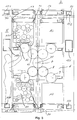
- FIGS. 1 and 2 printing towers 1, each with two printing units 5 arranged one above the other, of which FIG. 3 shows a further enlarged one, are shown in a lateral cross section and in a front view.
- a web-fed rotary printing press is formed by at least one printing unit 5 or a plurality of printing towers 1 arranged one behind the other, at least one folder 3 and at least one printing material roll stand 4.
- the printing units 5 are each constructed in a modular manner from a cylinder element 6 and four assigned, movable units 10.
- the cylinder element 6 is designed in the form of a satellite printing unit with a central cylinder 7, four blanket cylinders 8 and four form or plate cylinders 9 assigned to the blanket cylinders 8.
- the cylinder element 6 is rigidly attached to four stationary columns 30, which form lateral column pairs 30 for the printing units 5, while the units 10 can be moved in the rails 19 attached to the columns 30 in the direction of the axes of rotation 21 of the cylinders 7, 8, 9.
- the movable units 10 are each formed by an inking unit 11 and a dampening unit 15.
- the ink application rollers 12 and the dampening agent application rollers 16 can be pivoted away from the forme cylinders 9.
- the printing units 5 are each supported on the pairs of columns 30 arranged on their two sides, which together with connecting cross members 50, 150, 151, 152 form the essential part of a supporting structure 2.
- the printing units 5 are in this way framed by the lateral column pairs 30 and in each case an upper and a lower cross member 50.
- Each of the movable units 10 can be individually shifted in a straight line in the direction of the axes of rotation 21 of the cylinders 7, 8 and 9 between a working and a maintenance position.
- the units 10 run with rollers 20 in the running rails 19. In principle, however, other travel mechanisms are also conceivable.
- the two units 10 each arranged above a cylinder element 6 become hanging, and the units 10 each arranged below the cylinder element 6 are supported on the cross members 50 by the columns 30.
- the cylinder elements 6 arranged one above the other are supported on a pair of columns 30 on the right and on the left thereof, for example by corresponding alignment and connecting elements.
- the support structure 2 of the exemplary embodiment is sufficiently inherently rigid to carry both the cylinder elements and the inking and dampening units.
- the cylinder elements 6 can also be exchanged in a modular manner.
- the cylinder elements 6 can also be integrated into the supporting structure 2 in a stabilizing and load-bearing manner with a sufficiently stable design and a correspondingly firm bond with the columns 30. Corresponding compromises could be made in this case in the load-bearing capacity of the columns 30 and the cross beams 50, 150, 151, 152.
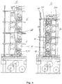
- Figure 4 in which equivalent components are provided with the same reference numerals, shows two printing units 5 on the left in a conventionally constructed printing tower 1 and, on the right, in comparison, the printing units of the printing tower 1 of Figure 1, which, in addition to the inherently rigid support structure, also has the further feature of the movable color - And dampening unit 10, so that the maximum space saving is achieved.
- the space requirement for a maintenance tunnel 60 which is necessary in the conventional printing tower 1 and which must remain free in the case of non-movable inking and dampening units 11, 15 in order to be able to carry out maintenance and repair work can be clearly seen.
- the color and dampening unit 10 can be completely omitted in the pressure tower 1 maintenance tunnel shown in FIG.
- the printing units 5 can be made flatter and narrower.
- the reduction in the pressure tower height in the exemplary embodiment is approximately 15% compared to the corresponding conventional pressure tower 1 on the left half of FIG. 4.
- the number of operating levels and the intermediate platforms are also significantly reduced in the supporting structure according to the invention.
- the support structure 2 is further developed by further columns 32, which are each arranged next to a pair of columns 30 in the longitudinal direction of the cylinders 7, 8, 9.
- the arrangement of the columns 32 is approximately mirror-symmetrical to that of the columns 30 to which they are connected by means of elongated cross members.
- the two left-hand columns 32 which only need to partially support the dead weight of the supporting structure 2, the units 10 moved out of the working position, the maintenance personnel and the equipment necessary for maintenance and repair, can be made weaker than the columns 30.
- the columns carry 32 another work crane 23 to support the work.
- a unit 10 which is in the disengaged state, ie in the maintenance position, is indicated in dashed lines.
- the parts of the inking and dampening unit 11 and 15 combined to form unit 10 are supplied with energy and possibly with data for a separate drive and possibly a control unit for the rollers of the movable unit 10 via a fixed plug connection 21.
- the lifting crane 23 can be used for a lower lifting load than is more conventional for the printing units Printing presses would be necessary, which in turn entails cost advantages.
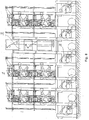
- FIG. 5 shows the pressure tower 1 from FIG. 1 in a top view, in which the column pairs 30 can be seen laterally from the two units 10 arranged next to one another and movable in the direction of the arrows A. Furthermore, a working platform 35 which is movable in the direction of arrow B transversely to the extension direction of the units 10 is indicated. Such work platforms 35 are again shown more clearly in FIG. 6 together with several units 10 moved out into the maintenance position. The work platforms 35 can each be guided under and / or over the extended units 10 of the printing units 5 along further various cross members. It is also possible to move the work platforms freely if other floors are provided on the various supports.
- the advantages of the invention come into play particularly when the printing press is arranged in a row by a plurality of printing units 5 or printing towers 1, each with a plurality of printing units 5 arranged one above the other, each with a plurality of inking and / or dampening units 11 and 15 is formed.
- the greatest cost savings and the largest space savings in terms of press length and height are expected.
- the movability of the inking and dampening units according to the invention moreover, no space is required, which would not also occur with permanently installed inking and dampening units, since their rollers and / or cylinders would also have to be pulled out of the printing machine when changing in the direction of their axes of rotation.
- the known printing presses with otherwise movable inking and dampening units always require additional space, which would not arise with a fixed arrangement.
- the concept of working platforms that can be moved under the extended fab and dampening units also contributes to saving space without requiring concessions on accessibility.
- Each inking unit and dampening unit in its maintenance position is freely accessible from three sides per printing unit.
- the support structure according to the invention enables this high degree of modularity, including the movability of the inking and dampening unit, which benefits the simple installation of the printing press and the need to change machine parts later on.
- FIG. 6 shows a front view of the printing tower of FIG. 5, in which a unit 10 of a lower and an upper printing unit is extended in the maintenance position in the direction of the axis of rotation 21 of the cylinders 7, 8, 9. It can also be seen that a work platform 35 for a lower and an upper printing unit 5 can be moved in the direction of arrow B transversely to the extension direction of the units 10. In doing so, the units 10 with the work platforms are driven under or over. It can also be seen that no additional intermediate platforms corresponding to the conventional design according to FIG. 4 are necessary for operating the units 10.
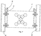
- FIG. 7 shows a detail from the front view of FIG. 3, in which a cylinder element 6 is detachably attached to the columns 30 by means of spherical alignment and connecting elements 17.
- the cylinder elements 6 are aligned in the vertical direction between the columns 30 and in the horizontal direction between the various cross members (50, 150, 151, 152) by means of the alignment and connecting elements 17, 18.
- the units 10 are aligned by aligning the running rails 19, as shown in FIG. 3, which are fastened with the same alignment and connecting elements 17, 18, not shown, as the cylinder elements 6.
- Figure 8 shows a further embodiment of the support structure according to the invention.
- a web-fed rotary printing press shown in a front view consists of at least one printing unit 5, a folder 3 and a printing-material roll stand 4 Folder also divided into different cylinder elements, not shown, which are designed so that they can be aligned with the cylinder elements 6 and detachably attached to the columns 30.
- the substrate roll stands 4 are attached to the columns 30 in the same way.
- the support frame according to the invention which is supported on the machine foundation, the costly customary machine table substructure can be dispensed with as a substantial cost saving.
- the folder and roll stand elements can also be moved in the direction of the axis of rotation 21 between a work and maintenance position.
Landscapes
- Engineering & Computer Science (AREA)
- Mechanical Engineering (AREA)
- Rotary Presses (AREA)
- Rolls And Other Rotary Bodies (AREA)
Applications Claiming Priority (2)
| Application Number | Priority Date | Filing Date | Title |
|---|---|---|---|
| DE4327278 | 1993-08-13 | ||
| DE4327278A DE4327278C5 (de) | 1993-08-13 | 1993-08-13 | Traggestell für eine Rollenrotationsdruckmaschine |
Publications (3)
| Publication Number | Publication Date |
|---|---|
| EP0638419A1 true EP0638419A1 (fr) | 1995-02-15 |
| EP0638419B1 EP0638419B1 (fr) | 1999-05-06 |
| EP0638419B2 EP0638419B2 (fr) | 2005-03-16 |
Family
ID=6495155
Family Applications (1)
| Application Number | Title | Priority Date | Filing Date |
|---|---|---|---|
| EP94810385A Expired - Lifetime EP0638419B2 (fr) | 1993-08-13 | 1994-06-29 | Cadre porteur pour une presse rotative à bobines |
Country Status (4)
| Country | Link |
|---|---|
| EP (1) | EP0638419B2 (fr) |
| DE (2) | DE4327278C5 (fr) |
| ES (1) | ES2133519T3 (fr) |
| FI (1) | FI943725A (fr) |
Cited By (16)
| Publication number | Priority date | Publication date | Assignee | Title |
|---|---|---|---|---|
| EP0813962A2 (fr) * | 1996-06-19 | 1997-12-29 | MAN Roland Druckmaschinen AG | Dispositif por remplir des cavités d'un cylindre, dispositif de raclage et procédé d'interchanger le liquide |
| DE19833468A1 (de) * | 1998-07-24 | 2000-01-27 | Koenig & Bauer Ag | Druckeinheit |
| WO2000006384A1 (fr) * | 1998-07-24 | 2000-02-10 | Koenig & Bauer Aktiengesellschaft | Machine offset rotative |
| DE10008217A1 (de) * | 2000-02-23 | 2001-08-30 | Roland Man Druckmasch | Transportvorrichtung für ein Druckwerkmodul |
| WO2002007972A1 (fr) * | 2000-07-22 | 2002-01-31 | Koenig & Bauer Aktiengesellschaft | Unite d'impression d'une machine d'impression offset dotee de modules de bati separables |
| US6363848B1 (en) | 1998-07-24 | 2002-04-02 | Koenig & Bauer Aktiengesellschaft | Printing unit with cylinders arranged in the shape of a “V” and “W” |
| US6408746B1 (en) | 1998-07-24 | 2002-06-25 | Koenig & Bauer Aktiengesellschaft | Printing unit |
| WO2004067275A1 (fr) * | 2003-01-30 | 2004-08-12 | Koenig & Bauer Aktiengesellschaft | Presse a imprimer, mode d'utilisation de la presse a imprimer et produits d'impression |
| DE10321989A1 (de) * | 2003-01-30 | 2004-08-19 | Koenig & Bauer Ag | Druckmaschine |
| DE102004008770A1 (de) * | 2004-02-23 | 2005-09-15 | Koenig & Bauer Ag | Rollenrotationsdruckmaschine |
| EP1598184A3 (fr) * | 2003-01-30 | 2005-11-30 | Koenig & Bauer Aktiengesellschaft | Machine d'impression, mode opératoire de la presse ainsi que le produit obtenu par la presse |
| US7156019B2 (en) | 2001-10-05 | 2007-01-02 | Koenig & Bauer Aktiengesellschaft | Rotary roller printing press |
| WO2007004053A3 (fr) * | 2005-07-06 | 2007-04-26 | Pakgoiz Mario Javier | Machine pour impression lithographique de fer blanc |
| EP1900522A1 (fr) * | 2004-04-05 | 2008-03-19 | Koenig & Bauer Aktiengesellschaft | Unité d'impression d'une machine d'impression rotative |
| DE102006042884A1 (de) * | 2006-09-13 | 2008-03-27 | Gallus Druckmaschinen Gmbh | Druckmaschine |
| EP2036723A2 (fr) * | 2007-09-14 | 2009-03-18 | manroland AG | Unité d'impression d'une rotative à bobines |
Families Citing this family (13)
| Publication number | Priority date | Publication date | Assignee | Title |
|---|---|---|---|---|
| DE19805898C2 (de) * | 1998-02-13 | 2003-09-18 | Roland Man Druckmasch | Druckwerk für eine Rollenrotationsdruckmaschine |
| DE10035785A1 (de) * | 2000-07-22 | 2002-02-07 | Koenig & Bauer Ag | Druckwerk einer Offsetrotationsdruckmaschine |
| DE10261999B4 (de) * | 2002-05-25 | 2015-01-29 | Windmöller & Hölscher Kg | Druckmaschine mit Trittblech zum Erreichen der oberen Farbwerke |
| DE10260574A1 (de) | 2002-12-21 | 2004-07-01 | Man Roland Druckmaschinen Ag | Modulare Druckeinheit |
| DE102004037889B4 (de) | 2004-04-05 | 2006-05-11 | Koenig & Bauer Ag | Vorrichtung zur Lagerung eines Zylinders und Druckeinheit mit wenigstens drei als Druckwerk zusammen wirkenden Zylindern |
| JP4705632B2 (ja) | 2004-04-05 | 2011-06-22 | ケーニツヒ ウント バウエル アクチエンゲゼルシヤフト | 輪転印刷機の印刷ユニット |
| WO2005097503A2 (fr) | 2004-04-05 | 2005-10-20 | Koenig & Bauer Aktiengesellschaft | Systemes d'entrainement d'une unite d'impression |
| EP1871601B1 (fr) | 2005-04-21 | 2008-10-29 | Koenig & Bauer Aktiengesellschaft | Groupe d'impression pourvu d'au moins deux cylindres cooperant |
| DE102005035875A1 (de) * | 2005-07-30 | 2007-02-15 | Man Roland Druckmaschinen Ag | Druckeinheit einer Druckmaschine sowie Druckmaschine |
| DE102006030290B3 (de) | 2006-03-03 | 2007-10-18 | Koenig & Bauer Aktiengesellschaft | Druckwerk |
| DE102006030457A1 (de) * | 2006-07-01 | 2008-01-03 | Man Roland Druckmaschinen Ag | Druckeinheit einer Rollenrotationsdruckmaschine |
| DE102007025499A1 (de) * | 2007-06-01 | 2008-12-04 | Manroland Ag | Rotationsdruckmaschine |
| DE102008025650A1 (de) * | 2008-05-28 | 2009-12-10 | Gallus Stanz- Und Druckmaschinen Gmbh | Druckwerk zum Bedrucken einer Bedruckstoffbahn in einer Druckmaschine |
Citations (6)
| Publication number | Priority date | Publication date | Assignee | Title |
|---|---|---|---|---|
| DE1169959B (de) * | 1962-04-13 | 1964-05-14 | Koenig & Bauer Schnellpressfab | Mehrfarben-Bogenrotationsmaschine fuer Hochdruck |
| FR2420426A1 (fr) * | 1978-03-22 | 1979-10-19 | Chambon Machines | Imprimeuse rotative a plusieurs couleurs et a format variable |
| EP0186862A2 (fr) * | 1984-12-20 | 1986-07-09 | J.G. Mailänder GmbH & Co. | Machine d'impression rotative du type à satellite |
| EP0308942A2 (fr) * | 1987-09-25 | 1989-03-29 | Miyakoshi Printing Machinery Co., Ltd. | Machine à imprimer rotative comportant des unités d'impression interchangeables |
| EP0315917A2 (fr) * | 1987-11-06 | 1989-05-17 | Miyakoshi Printing Machinery Co., Ltd. | Machine à rotative avec une unité de tambours interchangeables |
| EP0573877A1 (fr) * | 1992-06-12 | 1993-12-15 | MAN Roland Druckmaschinen AG | Machine à imprimer, en particulier pour imprimer une bande de papier carton massif ou rigide, avec des cylindres d'impression échangeables |
Family Cites Families (10)
| Publication number | Priority date | Publication date | Assignee | Title |
|---|---|---|---|---|
| US2460504A (en) * | 1944-10-24 | 1949-02-01 | William C Huebner | Printing apparatus |
| GB1104406A (en) * | 1965-07-30 | 1968-02-28 | Simon Ltd Henry | Improvements in or relating to in-iine machine unit installations |
| US4046070A (en) * | 1974-04-22 | 1977-09-06 | James Halley & Sons Limited | Rotary printing presses |
| SE7504029L (sv) * | 1975-04-08 | 1976-10-09 | Wifag Maschf | Falsapparat med sasom kasett utbytbar falsmekanism |
| US4384522A (en) * | 1977-12-07 | 1983-05-24 | Paper Converting Machine Company | Apparatus for producing business forms |
| DE2924591A1 (de) * | 1979-06-19 | 1981-01-22 | Maschf Augsburg Nuernberg Ag | Unterbau fuer eine rollen-rotationsdruckmaschine |
| GB8611722D0 (en) * | 1986-05-14 | 1986-06-25 | Drg Uk Ltd | Processing paper & other webs |
| DE3626287C3 (de) * | 1986-08-02 | 1997-04-03 | Koenig & Bauer Albert Ag | Falzapparat |
| DE9017332U1 (de) * | 1990-12-21 | 1991-03-21 | Baldwin-Gegenheimer GmbH, 8900 Augsburg | Vorrichtung zum flächenhaften Auftragen von streichfähigen Medien auf ein Trägermaterial |
| JPH0773908B2 (ja) * | 1991-06-21 | 1995-08-09 | 株式会社東京機械製作所 | 輪転印刷機 |
-
1993
- 1993-08-13 DE DE4327278A patent/DE4327278C5/de not_active Expired - Fee Related
-
1994
- 1994-06-29 DE DE59408202T patent/DE59408202D1/de not_active Expired - Fee Related
- 1994-06-29 ES ES94810385T patent/ES2133519T3/es not_active Expired - Lifetime
- 1994-06-29 EP EP94810385A patent/EP0638419B2/fr not_active Expired - Lifetime
- 1994-08-12 FI FI943725A patent/FI943725A/fi not_active IP Right Cessation
Patent Citations (6)
| Publication number | Priority date | Publication date | Assignee | Title |
|---|---|---|---|---|
| DE1169959B (de) * | 1962-04-13 | 1964-05-14 | Koenig & Bauer Schnellpressfab | Mehrfarben-Bogenrotationsmaschine fuer Hochdruck |
| FR2420426A1 (fr) * | 1978-03-22 | 1979-10-19 | Chambon Machines | Imprimeuse rotative a plusieurs couleurs et a format variable |
| EP0186862A2 (fr) * | 1984-12-20 | 1986-07-09 | J.G. Mailänder GmbH & Co. | Machine d'impression rotative du type à satellite |
| EP0308942A2 (fr) * | 1987-09-25 | 1989-03-29 | Miyakoshi Printing Machinery Co., Ltd. | Machine à imprimer rotative comportant des unités d'impression interchangeables |
| EP0315917A2 (fr) * | 1987-11-06 | 1989-05-17 | Miyakoshi Printing Machinery Co., Ltd. | Machine à rotative avec une unité de tambours interchangeables |
| EP0573877A1 (fr) * | 1992-06-12 | 1993-12-15 | MAN Roland Druckmaschinen AG | Machine à imprimer, en particulier pour imprimer une bande de papier carton massif ou rigide, avec des cylindres d'impression échangeables |
Cited By (38)
| Publication number | Priority date | Publication date | Assignee | Title |
|---|---|---|---|---|
| US6095045A (en) * | 1996-06-19 | 2000-08-01 | Man Roland Druckmaschinen Ag | Device for filling depressions in a cylinder; doctor blade device for this purpose and process for changing it |
| EP0813962A3 (fr) * | 1996-06-19 | 1998-09-09 | MAN Roland Druckmaschinen AG | Dispositif por remplir des cavités d'un cylindre, dispositif de raclage et procédé d'interchanger le liquide |
| EP0813962A2 (fr) * | 1996-06-19 | 1997-12-29 | MAN Roland Druckmaschinen AG | Dispositif por remplir des cavités d'un cylindre, dispositif de raclage et procédé d'interchanger le liquide |
| US6408746B1 (en) | 1998-07-24 | 2002-06-25 | Koenig & Bauer Aktiengesellschaft | Printing unit |
| DE19833468A1 (de) * | 1998-07-24 | 2000-01-27 | Koenig & Bauer Ag | Druckeinheit |
| DE19833468C2 (de) * | 1998-07-24 | 2000-05-18 | Koenig & Bauer Ag | Druckwerke |
| WO2000006385A1 (fr) * | 1998-07-24 | 2000-02-10 | Koenig & Bauer Aktiengesellschaft | Unites d'impression offset a cinq cylindres a ecart variable |
| WO2000006384A1 (fr) * | 1998-07-24 | 2000-02-10 | Koenig & Bauer Aktiengesellschaft | Machine offset rotative |
| US6363848B1 (en) | 1998-07-24 | 2002-04-02 | Koenig & Bauer Aktiengesellschaft | Printing unit with cylinders arranged in the shape of a “V” and “W” |
| US6474232B1 (en) | 1998-07-24 | 2002-11-05 | Koenig & Bauer Aktiengesellschaft | Rotary offset printing machine |
| US6539857B1 (en) | 1998-07-24 | 2003-04-01 | Koenig & Bauer Aktiengesellschaft | Five-cylinder offset printing units with adjustable spacing |
| DE10008217A1 (de) * | 2000-02-23 | 2001-08-30 | Roland Man Druckmasch | Transportvorrichtung für ein Druckwerkmodul |
| DE10008217B4 (de) * | 2000-02-23 | 2007-06-14 | Man Roland Druckmaschinen Ag | Transportvorrichtung für ein Druckwerkmodul |
| WO2002007972A1 (fr) * | 2000-07-22 | 2002-01-31 | Koenig & Bauer Aktiengesellschaft | Unite d'impression d'une machine d'impression offset dotee de modules de bati separables |
| US6786151B2 (en) | 2000-07-22 | 2004-09-07 | Koenig & Bauer Aktiengesellschaft | Printer of an offset printing machine with separable frame modules |
| EP1524115A2 (fr) * | 2000-07-22 | 2005-04-20 | Koenig & Bauer Aktiengesellschaft | Unité d'impression d'une machine d'impression offset planétaire |
| EP1524115A3 (fr) * | 2000-07-22 | 2007-08-29 | Koenig & Bauer Aktiengesellschaft | Unité d'impression d'une machine d'impression offset planétaire |
| US7448320B2 (en) | 2001-10-05 | 2008-11-11 | Koenig & Bauer Aktiengesellschaft | Printing unit and a rotary roller printing press |
| US7546801B2 (en) | 2001-10-05 | 2009-06-16 | Koenig & Bauer Aktiengesellschaft | Printing unit and a rotary roller printing press |
| US7296516B2 (en) | 2001-10-05 | 2007-11-20 | Koenig & Bauer Aktiengesellschaft | Rotary roller printing press |
| US7159512B2 (en) | 2001-10-05 | 2007-01-09 | Koenig & Bauer Aktiengesellschaft | Printing unit and a rotary roller printing press |
| US7562623B2 (en) | 2001-10-05 | 2009-07-21 | Koenig & Bauer Aktiengesellschaft | Printing unit and a rotary roller printing press |
| US7156019B2 (en) | 2001-10-05 | 2007-01-02 | Koenig & Bauer Aktiengesellschaft | Rotary roller printing press |
| DE10321989A1 (de) * | 2003-01-30 | 2004-08-19 | Koenig & Bauer Ag | Druckmaschine |
| GB2404168B (en) * | 2003-01-30 | 2006-09-20 | Koenig & Bauer Ag | Printing machine, modus operandi of said printing machine and printed products |
| EP1598184A3 (fr) * | 2003-01-30 | 2005-11-30 | Koenig & Bauer Aktiengesellschaft | Machine d'impression, mode opératoire de la presse ainsi que le produit obtenu par la presse |
| DE10321989B4 (de) * | 2003-01-30 | 2005-10-06 | Koenig & Bauer Ag | Druckmaschine |
| GB2404168A (en) * | 2003-01-30 | 2005-01-26 | Koenig & Bauer Ag | Printing machine, modus operandi of said printing machine and printed products |
| WO2004067275A1 (fr) * | 2003-01-30 | 2004-08-12 | Koenig & Bauer Aktiengesellschaft | Presse a imprimer, mode d'utilisation de la presse a imprimer et produits d'impression |
| DE102004008770A1 (de) * | 2004-02-23 | 2005-09-15 | Koenig & Bauer Ag | Rollenrotationsdruckmaschine |
| DE102004008770B4 (de) * | 2004-02-23 | 2007-09-20 | Koenig & Bauer Aktiengesellschaft | Rollenrotationsdruckmaschine |
| EP1900522A1 (fr) * | 2004-04-05 | 2008-03-19 | Koenig & Bauer Aktiengesellschaft | Unité d'impression d'une machine d'impression rotative |
| EP1894719A3 (fr) * | 2004-04-05 | 2011-04-13 | Koenig & Bauer Aktiengesellschaft | Unité d'impression d'une rotative à bobines |
| WO2007004053A3 (fr) * | 2005-07-06 | 2007-04-26 | Pakgoiz Mario Javier | Machine pour impression lithographique de fer blanc |
| DE102006042884A1 (de) * | 2006-09-13 | 2008-03-27 | Gallus Druckmaschinen Gmbh | Druckmaschine |
| US7980176B2 (en) | 2006-09-13 | 2011-07-19 | Heidelberger Druckmaschinen, Ag | Printing machine |
| EP2036723A2 (fr) * | 2007-09-14 | 2009-03-18 | manroland AG | Unité d'impression d'une rotative à bobines |
| EP2036723A3 (fr) * | 2007-09-14 | 2011-07-27 | manroland AG | Unité d'impression d'une rotative à bobines |
Also Published As
| Publication number | Publication date |
|---|---|
| DE4327278C2 (de) | 2001-03-22 |
| EP0638419B1 (fr) | 1999-05-06 |
| FI943725A0 (fi) | 1994-08-12 |
| ES2133519T3 (es) | 1999-09-16 |
| FI943725A (fi) | 1995-02-14 |
| DE59408202D1 (de) | 1999-06-10 |
| DE4327278C5 (de) | 2005-09-22 |
| EP0638419B2 (fr) | 2005-03-16 |
| DE4327278A1 (de) | 1995-02-16 |
Similar Documents
| Publication | Publication Date | Title |
|---|---|---|
| EP0638419B1 (fr) | Cadre porteur pour une presse rotative à bobines | |
| EP0749369B1 (fr) | Groupe imprimant pour rotative a bobines pour impression en couleurs | |
| EP0186862B1 (fr) | Machine d'impression rotative du type à satellite | |
| DE10008215A1 (de) | Druckwerk für eine Rotationsmaschine mit Kreuzschlitten | |
| EP0745031B1 (fr) | Groupe imprimant pour rotative a bobines pour impression en couleurs | |
| EP1100681B1 (fr) | Unites d'impression offset a cinq cylindres a ecart variable | |
| EP1303401B1 (fr) | Unite d'impression d'une machine d'impression offset dotee de modules de bati separables | |
| DE19805898A1 (de) | Druckwerk für eine Rollenrotationsdruckmaschine | |
| DE10261999A1 (de) | Druckmaschine mit Trittblech zum Erreichen der oberen Farbwerke | |
| EP1303405B1 (fr) | Groupe d'impression d'une machine offset rotative | |
| DE19516653C1 (de) | Rotationsdruckmaschine mit abschwenkbaren Gummizylindern | |
| EP1100680B1 (fr) | Machine offset rotative | |
| DE19833469C2 (de) | Offsetdruckmaschine | |
| EP1102679B1 (fr) | Unite d'impression | |
| EP1578607B1 (fr) | Unite d'impression modulaire | |
| DE102004011070B4 (de) | Ausbaubare Druckeinheit für Rollen-Offsetdruckmaschinen | |
| EP1365916B1 (fr) | Unite d'impression | |
| DE102006008303B3 (de) | Rotationsdruckmaschine | |
| DE102016124332A1 (de) | Rotationsdruckmaschine | |
| DE20023116U1 (de) | Druckwerk einer Offsetrotationsdruckmaschine | |
| DE102004019018A1 (de) | Bogen-Rotationsdruckmaschine für den Trockenoffset mit Kürzfarbwerk in Reihenbauform (Reihenbauart) |
Legal Events
| Date | Code | Title | Description |
|---|---|---|---|
| PUAI | Public reference made under article 153(3) epc to a published international application that has entered the european phase |
Free format text: ORIGINAL CODE: 0009012 |
|
| AK | Designated contracting states |
Kind code of ref document: A1 Designated state(s): BE CH DE ES FR GB IT LI NL SE |
|
| 17P | Request for examination filed |
Effective date: 19950419 |
|
| 17Q | First examination report despatched |
Effective date: 19961029 |
|
| GRAG | Despatch of communication of intention to grant |
Free format text: ORIGINAL CODE: EPIDOS AGRA |
|
| GRAG | Despatch of communication of intention to grant |
Free format text: ORIGINAL CODE: EPIDOS AGRA |
|
| GRAH | Despatch of communication of intention to grant a patent |
Free format text: ORIGINAL CODE: EPIDOS IGRA |
|
| GRAH | Despatch of communication of intention to grant a patent |
Free format text: ORIGINAL CODE: EPIDOS IGRA |
|
| GRAA | (expected) grant |
Free format text: ORIGINAL CODE: 0009210 |
|
| AK | Designated contracting states |
Kind code of ref document: B1 Designated state(s): BE CH DE ES FR GB IT LI NL SE |
|
| PG25 | Lapsed in a contracting state [announced via postgrant information from national office to epo] |
Ref country code: NL Free format text: LAPSE BECAUSE OF FAILURE TO SUBMIT A TRANSLATION OF THE DESCRIPTION OR TO PAY THE FEE WITHIN THE PRESCRIBED TIME-LIMIT Effective date: 19990506 Ref country code: ES Free format text: LAPSE BECAUSE OF FAILURE TO SUBMIT A TRANSLATION OF THE DESCRIPTION OR TO PAY THE FEE WITHIN THE PRESCRIBED TIME-LIMIT Effective date: 19990506 |
|
| REG | Reference to a national code |
Ref country code: CH Ref legal event code: EP |
|
| GBT | Gb: translation of ep patent filed (gb section 77(6)(a)/1977) |
Effective date: 19990510 |
|
| REF | Corresponds to: |
Ref document number: 59408202 Country of ref document: DE Date of ref document: 19990610 |
|
| ET | Fr: translation filed | ||
| REG | Reference to a national code |
Ref country code: ES Ref legal event code: FG2A Ref document number: 2133519 Country of ref document: ES Kind code of ref document: T3 |
|
| PLAV | Examination of admissibility of opposition |
Free format text: ORIGINAL CODE: EPIDOS OPEX |
|
| PLBI | Opposition filed |
Free format text: ORIGINAL CODE: 0009260 |
|
| PLBF | Reply of patent proprietor to notice(s) of opposition |
Free format text: ORIGINAL CODE: EPIDOS OBSO |
|
| 26 | Opposition filed |
Opponent name: KOENIG & BAUER AKTIENGESELLSCHAFT -LIZENZEN-PATENT Effective date: 20000204 |
|
| NLR1 | Nl: opposition has been filed with the epo |
Opponent name: KOENIG & BAUER AKTIENGESELLSCHAFT -LIZENZEN-PATENT |
|
| PLBF | Reply of patent proprietor to notice(s) of opposition |
Free format text: ORIGINAL CODE: EPIDOS OBSO |
|
| RDAH | Patent revoked |
Free format text: ORIGINAL CODE: EPIDOS REVO |
|
| REG | Reference to a national code |
Ref country code: GB Ref legal event code: IF02 |
|
| APAC | Appeal dossier modified |
Free format text: ORIGINAL CODE: EPIDOS NOAPO |
|
| APAE | Appeal reference modified |
Free format text: ORIGINAL CODE: EPIDOS REFNO |
|
| APAC | Appeal dossier modified |
Free format text: ORIGINAL CODE: EPIDOS NOAPO |
|
| PLBP | Opposition withdrawn |
Free format text: ORIGINAL CODE: 0009264 |
|
| APBY | Invitation to file observations in appeal sent |
Free format text: ORIGINAL CODE: EPIDOSNOBA2O |
|
| APCA | Receipt of observations in appeal recorded |
Free format text: ORIGINAL CODE: EPIDOSNOBA4O |
|
| APBU | Appeal procedure closed |
Free format text: ORIGINAL CODE: EPIDOSNNOA9O |
|
| PGFP | Annual fee paid to national office [announced via postgrant information from national office to epo] |
Ref country code: NL Payment date: 20040617 Year of fee payment: 11 |
|
| PGFP | Annual fee paid to national office [announced via postgrant information from national office to epo] |
Ref country code: ES Payment date: 20040622 Year of fee payment: 11 |
|
| PGFP | Annual fee paid to national office [announced via postgrant information from national office to epo] |
Ref country code: SE Payment date: 20040623 Year of fee payment: 11 Ref country code: BE Payment date: 20040623 Year of fee payment: 11 |
|
| PUAH | Patent maintained in amended form |
Free format text: ORIGINAL CODE: 0009272 |
|
| STAA | Information on the status of an ep patent application or granted ep patent |
Free format text: STATUS: PATENT MAINTAINED AS AMENDED |
|
| 27A | Patent maintained in amended form |
Effective date: 20050316 |
|
| AK | Designated contracting states |
Kind code of ref document: B2 Designated state(s): BE CH DE ES FR GB IT LI NL SE |
|
| REG | Reference to a national code |
Ref country code: CH Ref legal event code: AEN Free format text: AUFRECHTERHALTUNG DES PATENTES IN GEAENDERTER FORM |
|
| NLR2 | Nl: decision of opposition |
Effective date: 20050316 |
|
| GBTA | Gb: translation of amended ep patent filed (gb section 77(6)(b)/1977) | ||
| PG25 | Lapsed in a contracting state [announced via postgrant information from national office to epo] |
Ref country code: IT Free format text: LAPSE BECAUSE OF NON-PAYMENT OF DUE FEES;WARNING: LAPSES OF ITALIAN PATENTS WITH EFFECTIVE DATE BEFORE 2007 MAY HAVE OCCURRED AT ANY TIME BEFORE 2007. THE CORRECT EFFECTIVE DATE MAY BE DIFFERENT FROM THE ONE RECORDED. Effective date: 20050629 |
|
| PG25 | Lapsed in a contracting state [announced via postgrant information from national office to epo] |
Ref country code: BE Free format text: LAPSE BECAUSE OF NON-PAYMENT OF DUE FEES Effective date: 20050630 |
|
| PGFP | Annual fee paid to national office [announced via postgrant information from national office to epo] |
Ref country code: DE Payment date: 20050729 Year of fee payment: 12 |
|
| NLV1 | Nl: lapsed or annulled due to failure to fulfill the requirements of art. 29p and 29m of the patents act | ||
| PGFP | Annual fee paid to national office [announced via postgrant information from national office to epo] |
Ref country code: CH Payment date: 20050920 Year of fee payment: 12 |
|
| APAH | Appeal reference modified |
Free format text: ORIGINAL CODE: EPIDOSCREFNO |
|
| ET3 | Fr: translation filed ** decision concerning opposition | ||
| PGFP | Annual fee paid to national office [announced via postgrant information from national office to epo] |
Ref country code: FR Payment date: 20060621 Year of fee payment: 13 |
|
| PGFP | Annual fee paid to national office [announced via postgrant information from national office to epo] |
Ref country code: GB Payment date: 20060626 Year of fee payment: 13 |
|
| PG25 | Lapsed in a contracting state [announced via postgrant information from national office to epo] |
Ref country code: LI Free format text: LAPSE BECAUSE OF NON-PAYMENT OF DUE FEES Effective date: 20060630 Ref country code: CH Free format text: LAPSE BECAUSE OF NON-PAYMENT OF DUE FEES Effective date: 20060630 |
|
| PG25 | Lapsed in a contracting state [announced via postgrant information from national office to epo] |
Ref country code: DE Free format text: LAPSE BECAUSE OF NON-PAYMENT OF DUE FEES Effective date: 20070103 |
|
| REG | Reference to a national code |
Ref country code: CH Ref legal event code: PL |
|
| BERE | Be: lapsed |
Owner name: MASCHINENFABRIK *WIFAG Effective date: 20050630 |
|
| GBPC | Gb: european patent ceased through non-payment of renewal fee |
Effective date: 20070629 |
|
| REG | Reference to a national code |
Ref country code: FR Ref legal event code: ST Effective date: 20080229 |
|
| PG25 | Lapsed in a contracting state [announced via postgrant information from national office to epo] |
Ref country code: GB Free format text: LAPSE BECAUSE OF NON-PAYMENT OF DUE FEES Effective date: 20070629 |
|
| PG25 | Lapsed in a contracting state [announced via postgrant information from national office to epo] |
Ref country code: SE Free format text: LAPSE BECAUSE OF NON-PAYMENT OF DUE FEES Effective date: 20050630 |
|
| PG25 | Lapsed in a contracting state [announced via postgrant information from national office to epo] |
Ref country code: FR Free format text: LAPSE BECAUSE OF NON-PAYMENT OF DUE FEES Effective date: 20070702 |