EP0747196A1 - Plaque uniformément compressible - Google Patents
Plaque uniformément compressible Download PDFInfo
- Publication number
- EP0747196A1 EP0747196A1 EP96810360A EP96810360A EP0747196A1 EP 0747196 A1 EP0747196 A1 EP 0747196A1 EP 96810360 A EP96810360 A EP 96810360A EP 96810360 A EP96810360 A EP 96810360A EP 0747196 A1 EP0747196 A1 EP 0747196A1
- Authority
- EP
- European Patent Office
- Prior art keywords
- wall
- platen
- platen according
- support structure
- intermediate support
- Prior art date
- Legal status (The legal status is an assumption and is not a legal conclusion. Google has not performed a legal analysis and makes no representation as to the accuracy of the status listed.)
- Granted
Links
- 238000000465 moulding Methods 0.000 claims description 20
- 239000007924 injection Substances 0.000 claims description 7
- 238000002347 injection Methods 0.000 claims description 6
- 238000001746 injection moulding Methods 0.000 claims description 5
- 238000010926 purge Methods 0.000 claims description 4
- 230000001154 acute effect Effects 0.000 claims description 3
- 238000005452 bending Methods 0.000 description 8
- 238000013461 design Methods 0.000 description 6
- 230000015572 biosynthetic process Effects 0.000 description 3
- 230000007246 mechanism Effects 0.000 description 3
- 230000006835 compression Effects 0.000 description 2
- 238000007906 compression Methods 0.000 description 2
- 238000000034 method Methods 0.000 description 2
- 230000004048 modification Effects 0.000 description 2
- 238000012986 modification Methods 0.000 description 2
- 238000003825 pressing Methods 0.000 description 2
- 206010037544 Purging Diseases 0.000 description 1
- 230000009471 action Effects 0.000 description 1
- 230000008901 benefit Effects 0.000 description 1
- 239000006227 byproduct Substances 0.000 description 1
- 230000003247 decreasing effect Effects 0.000 description 1
- 238000009826 distribution Methods 0.000 description 1
- 238000005538 encapsulation Methods 0.000 description 1
- 238000003780 insertion Methods 0.000 description 1
- 230000037431 insertion Effects 0.000 description 1
- 238000004519 manufacturing process Methods 0.000 description 1
- 239000000463 material Substances 0.000 description 1
- 230000013011 mating Effects 0.000 description 1
- 230000007935 neutral effect Effects 0.000 description 1
- 230000002028 premature Effects 0.000 description 1
- 230000004044 response Effects 0.000 description 1
- 238000007789 sealing Methods 0.000 description 1
- 238000000926 separation method Methods 0.000 description 1
- 238000001721 transfer moulding Methods 0.000 description 1
Images


Classifications
-
- B—PERFORMING OPERATIONS; TRANSPORTING
- B29—WORKING OF PLASTICS; WORKING OF SUBSTANCES IN A PLASTIC STATE IN GENERAL
- B29C—SHAPING OR JOINING OF PLASTICS; SHAPING OF MATERIAL IN A PLASTIC STATE, NOT OTHERWISE PROVIDED FOR; AFTER-TREATMENT OF THE SHAPED PRODUCTS, e.g. REPAIRING
- B29C45/00—Injection moulding, i.e. forcing the required volume of moulding material through a nozzle into a closed mould; Apparatus therefor
- B29C45/17—Component parts, details or accessories; Auxiliary operations
- B29C45/1742—Mounting of moulds; Mould supports
- B29C45/1744—Mould support platens
Definitions
- the present invention is directed to platens used with molding machines and presses, and more particular to a platen having a design which allows for minimum platen deflection at minimum platen weight.
- Injection molding platens are typically block shaped as shown in U.S. Patent No. 5,188,850 to Hirata et al.; U.S. Patent No. 5,066,217 to Fukuzawa et al.; U.S. Patent No. 5,110,283 to Blüml et al.; U.S. Patent No. 5,162,782 to Yoshioka; and U.S. Patent No. 5,192,557 to Hirata et al.
- the mold platen is substantially block shaped having a substantially rectangular side which supports a mold half. During clamp-up of mold halves, a force is generated against the mold mounting face of the platen.
- the mold mounting face is caused to concavely deform, forcing the top and bottom edges of the side towards the oncoming force and causing the platen to bend and provide tension across the backside of the mold platen.
- the center of the platens separate causing a gap between the mold halves, and in some cases, the formation of flash is a by-product.
- U.S. Patent No. 4,615,857 to Baird discloses an encapsulation means and method for reducing flash during mold operations.
- injection and transfer molding of plastic is performed in a manner that virtually eliminates flash.
- Deflection of the mold press therein is measured with the mold press in the clamping configuration.
- the support structure of the mold is arranged to apply an equal force to the mold face by configuring supporting pillars and bars such that they act as individual springs against the mold face and in response to the force generated while the mold is in the clamping configuration.
- the spring constants and the lengths of the supporting pillars and bars are calculated to account for the actual deflection found in the mold press and thereby producing a uniform pressure on the molds during clamping of the press.
- the flexure of the mold platens during mold sealing is measured and the compressibility of the mold mounting blocks of the device are adjusted as a function of lateral position on one or both platens in order to compensate for platen flexure, so that a constant force is applied to the parting surface of the mold, independent of lateral position on the parting surface.
- the stiffness and length of the mounting blocks define the force provided by the mounting blocks and are determined in accordance with predetermined formulas depending upon the position of the block on the platen and the predetermined platen deflection. While Baird compensates for deflection, the method and apparatus by which this is achieved is quite complex requiring individual designs for particular forces to be generated with particular molds. Accordingly, a uniformly applicable design is not achieved.
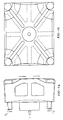
- FIGS. 1a and 1b disclose a prior art molding platen having a shape slightly different than the block shape platens discussed above in the cited patents.
- the mold platen has a profile including several openings therethrough, a front wall and a back wall.
- a plurality of slots and ribs extend toward the back wall which can and has a smaller surface area than the front wall of the platen.
- the platen also includes bores at each corner thereof for receiving tension bars that resist the force F between the platens during mold clamp-up.
- Each tie bar carries a resistance force F R as shown.
- the plurality of ribs and slots are provided for decreasing the weight of the platen.
- the front mold mounting face is under compression during mold clamp-up while the back wall is under tension as in a simple beam.
- the tie bars are drawn inwardly and deform to conform with platen face movement, as shown by the dotted line and arrows in Figure la, thereby causing the mold face to bend and have a concave configuration during molding, similar to the platens of the aforementioned patents. Accordingly, despite the design of the mold platen of FIGS. 1a and 1b, mold face bending is not compensated for and the possibility of the creation of flash is still existent. Since both sides of the platen bend, the supports at the corners of the tie bars also bend resulting in uneven loading of the tie bar supports. This causes bending of the tie bars and high stress concentrations leading to premature fatigue failure. Arrows C show how the tie bars are bent during clamp-up.
- the primary object of this invention is to provide a mold platen for use with molding or clamping or pressing applications which results in substantially flat and parallel mold mounting faces during clamp-up.
- Another object of this invention is to provide a mold platen for use in injection molding applications as above which is lightweight.
- Still another object of this invention is to provide a mold platen designed to direct clamping force during clamp-up from the tie bars at the edges of the platen towards the center mold mounting area of the platen eliminating any curvature of the platen.
- Still another object of this invention is to provide a mold platen having a mold mounting face which stays almost completely flat during clamp-up and substantially prevents the formation of flash.
- a further object of this invention is to provide a mold platen having two sides and an intermediate support structure which prevents the mold platen from non-uniformly deflecting at the molding side during clamp-up.
- Yet another object of this invention is to provide a mold platen having two walls and a central arch-shaped intermediate support structure between the two walls which substantially prevents non-uniform platen deflection at the molding side.
- Yet another object of this invention is to provide a mold platen having two sides and an intermediate conically-shaped support structure for substantially preventing non-uniform platen deflection at the molding side.
- Another object of the present invention is to provide a mold platen for eliminating uneven loading of tie bars and nuts during clamp-up.
- the foregoing objects are achieved by the mold platen of the present invention for use in a clamping operation wherein a force is generated having a first direction.
- the platen includes a first wall having edges and a center area and at least first and second sides, wherein the first side is adapted to be positioned nearest the clamping operation.
- the platen further includes a second wall spaced from and substantially parallel to the first wall, wherein the first and second walls extend substantially transverse to the first direction of the force.
- Means for directing the force from the edges of the second wall toward the center area of the first wall is provided for substantially preventing non-uniform deflection of the first wall along the first side.
- the purpose of the second wall is to resist the separation forces created by the intermediate structure.
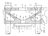
- platen 10 includes a mold mounting wall 12 adapted to hold a mold half 17, an end wall 14 and intermediate support structure 16 positioned between molding wall 12 and end wall 14.
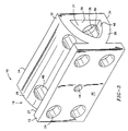
- FIGS. 4 and 5 represents additional embodiments of the platen of the present invention and from a general standpoint, the embodiments of FIGS. 2, 4 and 5 are similar.
- FIG. 4 represents the particularly preferred embodiment, i.e. one with angled instead of arched walls or one having a conically shaped intermediate portion, as shown in FIG. 5.
- FIG. 5 represents the particularly preferred embodiment, i.e. one with angled instead of arched walls or one having a conically shaped intermediate portion, as shown in FIG. 5.
- Mold mounting wall 12 is adapted to hold a mold half 17 for use in mating another mold half (not shown) for creating a mold and for sufficiently clamping the other mold half via clamping force F represented by the arrows. Reaction forces F R in tie bars 25 are further represented by the arrows. Mold mounting wall 12 is substantially rectangular in shape, although other shapes can be used, extends substantially transverse to force F, and preferably, on one of two platens on a machine, includes an aperture 18 through the center thereof for insertion of an injection unit 20. As shown in the cross-sectional view of FIG. 2, the tip 22 of injection unit 20 preferably extends through aperture 18 to connect with mold half 17 thereby contributing to efficient space utilization. Mold mounting wall 12 also includes a bore 24 being substantially larger in diameter than tie bar 25 at each corner thereof for receiving tie bars 25. Mold mounting wall 12 is adapted to receive four tie bars 25 which extend therethrough and toward end wall 14.
- Intermediate support structure 16 provides a mechanism by which mold mounting wall 12 of platen 10 is prevented from non-uniformly bending during the application of clamping force F and as a result of such non-uniform bending, preventing the creation of flash and wear on the components of the molding machine.
- Intermediate support structure 16 includes one or more internal ribs 26 and/or 28 extending from inner side 27 of mold mounting wall 12 to inner side 29 of end wall 14, causing the intermediate support structure to have a narrow end and a wide end.
- the intermediate support structure is preferably one continuous wall in a semi-spherical or conical shape which is attached to the end wall and mold mounting wall similar to as described below with respect to the upper and lower ribs.
- Ribs 26 and 28 are attached to and extend substantially outwardly from a central area 30 of inner side 27 of mold mounting wall 12, forming a narrow end, to the outer edges, 32 and 34, respectively, of the inner side 29 of end wall 14, forming a wide end and cavity 31 between ribs 26 and 28. Accordingly, central area 30 is located opposite the intended mold mounting area of mold mounting wall 12. Ribs 26 and 28 therefore support the platen face directly where the mold is located. Accordingly, in one embodiment, a singular upper rib 26 extends from central area 30 of mold mounting wall 12 to, and is attached with, an upper edge 32 of inner side 29 of end wall 14. Preferably, upper rib 26 is attached to and extends across the entire width of inner side 27 of molding wall 12 as shown in the perspective view of FIG.
- lower rib 28 is also attached to, and extends from central area 30, preferably along the entire width of inner side 27 of mold mounting wall 12 and is attached with the lower edge 34 of inner side 29 of wall 14. While ribs 26 and 28 have been described as substantially contiguous and extending across the entire width, the present invention also contemplates ribs 26 and 28 being comprised of a plurality of separate ribs having smaller widths and spaced from each other and not necessarily covering the entire width of the mold mounting and end walls.
- the resulting structure formed by upper rib 26 and lower rib 28 is substantially arch or C-shaped, wherein each rib is bowed outwardly relative cavity 31 of platen 10.
- upper rib 126 and lower rib 128 are substantially straight, extending from central area 130 to upper edge 132 and lower edge 134, respectively, of end wall 114.
- the resulting shape is substantially V-shaped.
- the cross-section taken horizontally could be substantially the same to define another embodiment, i.e. such as the conical version shown in FIG. 5.
- FIG. 4 would not include holes 124 and the portion of tie bars 125 seen in cavity 131 would not be seen since wall 226 would block the view.
- intermediate support structure 216 comprises a wall 226 which is conical or spherical in shape with the narrow portion of the conical or spherical shape attached to the inner surface 227 of mold mounting wall 212 and the wide portion of the conical or spherical shape attached to the inner surface 229 of end platen 214.
- the conical or spherical wall may be divided into sections for ease of manufacture, or may be a singular casted part. Due to the conical or spherical shape, the wall 226 of intermediate 216 typically would not extend across the entire width of the end and mold mounting walls as described above for the FIGS. 2 and 4 embodiments.
- the upper and lower ribs of the intermediate support structure or wall of the conically or spherically shaped support structure are attached with molding wall 12, 112, or 212, respectively, at an acute angle ⁇ thereto (not shown in FIG. 5, but similar to FIG. 4) and to end wall 14, 114, or 214, respectively, at an acute angle a thereto (not shown in FIG. 5, but similar to FIG. 4).
- End wall 14 is also preferably rectangular in shape, although other shapes may be used, and extends substantially parallel wall 12, transverse force F, and may include an aperture 36 therethrough in which injection unit 20 can be adapted to extend for injecting melt into mold half 17. Similar to molding wall 12, end wall 14 includes bores 38 in alignment with bores 24, one at each corner thereof, in order to receive tie bars therethrough. Each of bores 38 may include, if necessary, a countersink 40 for receiving tie bar nuts 42. Upper rib 26 and lower rib 28 may also include openings 48 and 50, respectively, therein and in alignment with bores 24 and 38 of walls 12 and 14 for receiving tie bars 25 as required.
- End wall 14 further can include purge openings 44 therein adjacent ribs 26 and 28, through which escaping melt, purgings and/or drool may exit from the platen by running down the inner surface 46 of lower rib 28 and through the purge opening 44.
- the platens as shown are formed from a casted material, it is also feasible the elements thereof, i.e. the walls and intermediate support structure, may be formed separately and fastened together in any manner which will provide the necessary strength to withstand forces developed during clamp-up.
- platen 10 can be used, for example, with both movable and stationary platens used in molding machines and mechanical presses or other clamping mechanisms wherein deflection of a platen is possible due to clamp-up forces generated, and in both singular and tandem designs of these molding machines and presses and other clamping mechanisms.
- intermediate support structure 16 and the arrangement of mold mounting wall 12 relative intermediate support structure 16 is such that the clamping forces F at the edges of the platens are directed towards the center of the platen where the mold half is located, i.e functioning on a bridge principle to provide support directly under the mold. Accordingly, the mold mounting face of the platen deforms in a substantially parallel manner thereby substantially preventing bending and the creation of flash.
- the force F which develops on the mold mounting surface of platen 10 during clamp-up is indicated by the large arrow in FIG. 2.
- the force F acting on the platen during mold clamp-up is dissipated outwardly as force F I , as indicated by the small arrows, along internal ribs 26 and 28 causing the intermediate support structure 16 to be in compression as indicated by the arrows C and causing the molding face of wall 12 to be in a neutral state in terms of bending forces acting unopposed thereon.
- end wall 14 is caused to be in tension as indicated by arrows T while the tie bars each with reaction force F R are pushed slightly outwardly due to stretching of end wall 14.
- the primary advantage of this invention is that a platen is provided for use with molding or clamping or pressing applications which results in substantially flat and parallel mold mounting faces during clamp-up.
- a platen is provided for use in injection molding applications which is lightweight.
- a platen is provided which is designed to direct clamping force during clamp-up from the tie bars at the edges of the platen towards the center mold mounting area of the platen, eliminating any curvature of the platen.
- a platen is provided having a mold mounting face which stays almost completely flat during clamp-up and substantially prevents the formation of flash.
- a platen is provided having two walls and an intermediate support structure which prevents the mold mounting side of the platen from non-uniformly deflecting during clamp-up.
- a platen is provided having two walls and a central arch-shaped intermediate support structure between the two walls which substantially prevents non-uniform platen deflection of the mold mounting side thereof.
- a platen is provided having two walls and an intermediate conically or spherically shaped support structure therebetween for substantially preventing non-uniform platen deflection at the molding side.
- Another object of the present invention is to provide a mold platen for eliminating uneven loading of tie bars and nuts during clamp up. Since bending of the platen is minimized, the loading of the tie bars is substantially uniform and any resulting tie bar bending is substantially eliminated.
Landscapes
- Engineering & Computer Science (AREA)
- Manufacturing & Machinery (AREA)
- Mechanical Engineering (AREA)
- Moulds For Moulding Plastics Or The Like (AREA)
- Handling Of Sheets (AREA)
- Diaphragms For Electromechanical Transducers (AREA)
- Polishing Bodies And Polishing Tools (AREA)
- Presses And Accessory Devices Thereof (AREA)
- Electroplating Methods And Accessories (AREA)
- Devices For Use In Laboratory Experiments (AREA)
Applications Claiming Priority (2)
| Application Number | Priority Date | Filing Date | Title |
|---|---|---|---|
| US482874 | 1995-06-07 | ||
| US08/482,874 US5593711A (en) | 1995-06-07 | 1995-06-07 | Uniformly compressible platen |
Publications (3)
| Publication Number | Publication Date |
|---|---|
| EP0747196A1 true EP0747196A1 (fr) | 1996-12-11 |
| EP0747196B1 EP0747196B1 (fr) | 2001-08-16 |
| EP0747196B2 EP0747196B2 (fr) | 2005-04-27 |
Family
ID=23917793
Family Applications (1)
| Application Number | Title | Priority Date | Filing Date |
|---|---|---|---|
| EP96810360A Expired - Lifetime EP0747196B2 (fr) | 1995-06-07 | 1996-06-04 | Plaque uniformément compressible |
Country Status (8)
| Country | Link |
|---|---|
| US (2) | US5593711A (fr) |
| EP (1) | EP0747196B2 (fr) |
| JP (1) | JP2858647B2 (fr) |
| AT (1) | ATE204226T1 (fr) |
| CA (1) | CA2177949C (fr) |
| DE (1) | DE69614451T3 (fr) |
| ES (1) | ES2162013T5 (fr) |
| MX (1) | MX9602232A (fr) |
Cited By (11)
| Publication number | Priority date | Publication date | Assignee | Title |
|---|---|---|---|---|
| WO1997031770A1 (fr) * | 1996-03-02 | 1997-09-04 | Abwicklungsgesellschaft Kunststoffmaschinen Werkstrasse Gmbh & Co. Kg | Dispositif de fermeture pour moule d'une presse d'injection |
| DE19855663C2 (de) * | 1997-12-03 | 2001-11-15 | Engel Gmbh Maschbau | Einrichtung zum Einleiten der Schließkraft bei einer Spritzgießmaschine |
| WO2002092318A1 (fr) * | 2001-05-12 | 2002-11-21 | Mannesmann Plastics Machinery Gmbh | Plateau de serrage de moule pour machine de moulage par injection et machine de moulage par injection comprenant deux plateaux de ce type |
| EP1287962A1 (fr) * | 2001-08-30 | 2003-03-05 | Battenfeld GmbH | Plateau d'une machine à mouler par injection |
| EP1275486A3 (fr) * | 2001-07-13 | 2003-06-04 | Sumitomo Heavy Industries, Ltd. | Machine de moulage comportant un dispositif de support mobile |
| WO2003084731A1 (fr) * | 2002-04-11 | 2003-10-16 | Krauss-Maffei Kunststofftechnik Gmbh | Plaque pour une machine de moulage par injection |
| KR100483849B1 (ko) * | 2001-07-13 | 2005-04-15 | 스미도모쥬기가이고교 가부시키가이샤 | 가동금형 지지장치를 구비한 성형기 |
| DE10349828A1 (de) * | 2003-10-25 | 2005-06-16 | W + S Solutions Gmbh & Co. Kg | Spritzgießmaschine mit integrierter Vorrichtung zur Austriebsminimierung an Spritzgießteilen |
| DE202008010066U1 (de) | 2007-08-16 | 2008-10-16 | Netstal-Maschinen Ag | Vorrichtung für eine Spritzgießmaschine mit einer Werkzeugaufspannplatte |
| DE102006038015B4 (de) * | 2005-09-26 | 2009-08-13 | Engel Austria Gmbh | Formaufspannplatte für eine Spritzgießmaschine |
| DE202011108818U1 (de) | 2011-12-08 | 2013-03-13 | Netstal-Maschinen Ag | Zwischenplatte für eine Spritzgießmaschine |
Families Citing this family (47)
| Publication number | Priority date | Publication date | Assignee | Title |
|---|---|---|---|---|
| US5593711A (en) * | 1995-06-07 | 1997-01-14 | Husky Injection Molding Systems Ltd. | Uniformly compressible platen |
| CN1070410C (zh) * | 1996-02-22 | 2001-09-05 | 东芝机械株式会社 | 精密注塑的夹紧装置 |
| US6027329A (en) * | 1997-03-15 | 2000-02-22 | Hpm/Stadco, Inc. | Platen having internal spring-like characteristics for preventing deformation of mold mounting face during clamping operations |
| BR9800139C1 (pt) | 1998-03-23 | 2000-03-14 | Ind Romi S A Ind Romi S A | Desenvolvimento em mecanismo de bloqueio de molde |
| TW386521U (en) * | 1998-06-18 | 2000-04-01 | Tsai Wen Feng | Improvement of labeling device for CD, optical disk |
| US6439876B1 (en) | 2000-10-30 | 2002-08-27 | Husky Injection Molding Systems, Ltd. | Injection molding machine having a platen for uniform distribution of clamping forces |
| DE10132970A1 (de) * | 2001-07-06 | 2003-01-23 | Mannesmann Plastics Machinery | Formaufspannplatte für eine Spritzgießmaschine |
| DE10144992A1 (de) * | 2001-09-12 | 2003-03-27 | Mpm Beteiligungs Gmbh | Formaufspannplatte einer Spritzgießmaschine |
| DE10214458A1 (de) * | 2002-03-30 | 2003-10-16 | Lehmann Gmbh & Co Kg | Vorrichtung zum Spritzgießen von Formteilen aus Kunststoff |
| US6855281B2 (en) * | 2002-10-28 | 2005-02-15 | The North Face Apparel Corp | Method of forming an article of footwear |
| US6905643B2 (en) * | 2002-12-04 | 2005-06-14 | Dow Global Technologies Inc. | Process for molding on a substrate |
| US7080978B2 (en) * | 2003-04-17 | 2006-07-25 | Husky Injection Molding Systems Ltd. | Platen |
| ITRM20040107A1 (it) * | 2004-03-02 | 2004-06-02 | Sipa Societa Industrializzazio | Dispositivo e metodo di condizionamento di oggetti in plastica. |
| WO2005084909A1 (fr) * | 2004-03-09 | 2005-09-15 | Sumitomo Heavy Industries, Ltd. | Dispositif de support de moule, machine à mouler et méthode de moulage |
| ITRM20040163A1 (it) * | 2004-03-30 | 2004-06-30 | Sipa Societa Industrializzazio | Apparato di stampaggio per soffiaggio di oggetti in plastica. |
| ITRM20040259A1 (it) * | 2004-05-25 | 2004-08-25 | Sipa Societa Industrializzazio | Traversa porta stampo per pressa di stampaggio e pressa comprendente tale traversa. |
| JP2006198801A (ja) * | 2005-01-18 | 2006-08-03 | Toyo Mach & Metal Co Ltd | 成形機 |
| US7491051B2 (en) | 2005-04-25 | 2009-02-17 | Mitsubishi Heavy Industries Plastic Technology Co., Ltd. | Mold clamping apparatus, injection molding machine and injection molding method |
| US20070035067A1 (en) * | 2005-08-09 | 2007-02-15 | Andreas Ujma | Molding machine plasticizing unit sub-assembly and a method of reducing shearing effects in the manufacture of plastic parts |
| US20070036879A1 (en) * | 2005-08-09 | 2007-02-15 | Andreas Ujma | Machine platen and an injection molding machine |
| JP4928133B2 (ja) * | 2006-02-13 | 2012-05-09 | 東洋機械金属株式会社 | 成形機 |
| JP4047892B2 (ja) * | 2006-03-23 | 2008-02-13 | ファナック株式会社 | 射出成形機の型締装置 |
| US7318721B2 (en) * | 2006-03-30 | 2008-01-15 | Husky Injection Molding Systems Ltd. | Molding-system platen |
| JP2008162103A (ja) * | 2006-12-27 | 2008-07-17 | Toshiba Mach Co Ltd | 型締装置と、この型締装置を備えた射出成形機 |
| US20080173190A1 (en) * | 2007-01-24 | 2008-07-24 | Husky Injection Molding Systems Ltd. | Molding-System Platen having Anti-Tilt Structure |
| US20080175944A1 (en) * | 2007-01-24 | 2008-07-24 | Husky Injection Molding Systems Ltd. | Molding-System Platen having Anti-Tilt Structure |
| US7798805B2 (en) * | 2007-01-24 | 2010-09-21 | Husky Injection Molding Systems Ltd. | Molding-system platen having tie-bar accommodation corners that resist coplanar disorientation |
| JP5247725B2 (ja) * | 2007-01-24 | 2013-07-24 | ハスキー インジェクション モールディング システムズ リミテッド | 共面位置狂いを抑えるタイバー収容コーナを有する成形システムプラテン |
| US20080175943A1 (en) * | 2007-01-24 | 2008-07-24 | Husky Injection Molding Systems Ltd. | Molding-System Platen having Anti-Tilt Structure |
| US7857612B2 (en) | 2007-01-24 | 2010-12-28 | Husky Injection Molding Systems Ltd. | Molding-system platen having anti-tilt structure |
| US7753668B2 (en) * | 2007-01-24 | 2010-07-13 | Husky Injection Molding Systems Ltd. | Platen assembly, molding system and method for platen orientation and alignment |
| JP4276274B2 (ja) * | 2007-07-04 | 2009-06-10 | ファナック株式会社 | 射出成形機の固定プラテン |
| JP4625489B2 (ja) * | 2007-09-18 | 2011-02-02 | 三菱重工プラスチックテクノロジー株式会社 | 型盤、型締め装置、射出成形機 |
| JP2010179623A (ja) * | 2009-02-09 | 2010-08-19 | Ube Machinery Corporation Ltd | 射出成形機のステーショナリプラテン |
| US20110200701A1 (en) * | 2009-12-21 | 2011-08-18 | Carsten Link | Platen for an injection molding machine |
| US8864485B2 (en) | 2010-12-03 | 2014-10-21 | Graham Engineering Corporation | Adjustable platen assembly for use in a clamp station |
| BR112013016857B1 (pt) | 2010-12-29 | 2018-05-15 | Av & R Vision & Robotiques Inc. | Máquina de fundição sob pressão de câmara fria e de fundição sob pressão de câmara quente, e, métodos de moldar um artigo metálico e de aplicar pressão na primeira e segunda porções do molde |
| US8646512B2 (en) | 2012-05-08 | 2014-02-11 | Honda Motor Co., Ltd. | Die brace and method of use thereof |
| JP5567066B2 (ja) * | 2012-05-30 | 2014-08-06 | 株式会社名機製作所 | 射出成形機 |
| JP5976567B2 (ja) * | 2013-02-14 | 2016-08-23 | 住友重機械工業株式会社 | 射出成形機 |
| US8840391B1 (en) * | 2013-03-29 | 2014-09-23 | Dan Sherrill | Drool shield for injection molding |
| AT514238B1 (de) | 2013-04-29 | 2015-02-15 | Engel Austria Gmbh | Vertikale Schließeinheit für eine Spritzgießmaschine |
| JP5800881B2 (ja) * | 2013-11-06 | 2015-10-28 | ファナック株式会社 | 射出成形機の金型取付盤 |
| JP5883045B2 (ja) | 2014-02-10 | 2016-03-09 | ファナック株式会社 | 射出成形機の固定プラテン |
| JP6329517B2 (ja) * | 2014-08-04 | 2018-05-23 | 日精樹脂工業株式会社 | 型締機構 |
| JP6383705B2 (ja) * | 2014-08-04 | 2018-08-29 | 日精樹脂工業株式会社 | 型締機構 |
| ES2829399T3 (es) | 2017-06-28 | 2021-05-31 | Diseno Y Desarrollo De Matriceria S L | Máquina de moldeo por inyección de plástico y método de moldeo |
Citations (4)
| Publication number | Priority date | Publication date | Assignee | Title |
|---|---|---|---|---|
| FR2284433A1 (fr) * | 1974-09-11 | 1976-04-09 | Hehl Karl | Groupe de serrage de moule pour machine a mouler par injection |
| EP0192814A2 (fr) * | 1985-02-19 | 1986-09-03 | Siebolt Hettinga | Procédé et dispositif de verrouillage |
| DE4004026A1 (de) * | 1989-02-15 | 1990-08-16 | Toshiba Machine Co Ltd | Form - klemmvorrichtung |
| WO1992011991A1 (fr) * | 1991-01-10 | 1992-07-23 | Cincinnati Milacron Inc. | Platine de support de moule |
Family Cites Families (20)
| Publication number | Priority date | Publication date | Assignee | Title |
|---|---|---|---|---|
| US1977549A (en) * | 1934-08-04 | 1934-10-16 | Rudolph W Glasner | Metal working press |
| US2807206A (en) * | 1952-09-01 | 1957-09-24 | Renault | Presses actuated by a fluid under pressure |
| US2719443A (en) * | 1953-03-16 | 1955-10-04 | Rohr Aircraft Corp | Drop hammer |
| US3669593A (en) * | 1970-02-10 | 1972-06-13 | Wilhelm Cyriax | Mold-closing means for molding machines |
| SE359257B (fr) * | 1972-01-03 | 1973-08-27 | Asea Ab | |
| US4243369A (en) * | 1978-12-05 | 1981-01-06 | Micro & Precision Mouldings (Cheltenham Limited) | Mould closing, clamping and opening means |
| SE429944B (sv) * | 1982-03-22 | 1983-10-10 | Fjellman Press Ab | Hogtryckspress |
| JPS6044200A (ja) * | 1983-08-22 | 1985-03-09 | Kootaki Kk | プレス装置 |
| US4615857A (en) * | 1984-11-30 | 1986-10-07 | Motorola, Inc. | Encapsulation means and method for reducing flash |
| US4976400A (en) * | 1989-06-16 | 1990-12-11 | General Motors Corporation | Plastic tooling with compression adjustment |
| JPH0383120A (ja) * | 1989-08-28 | 1991-04-09 | Mitsubishi Electric Corp | 座標入力機能付表示装置 |
| US5059105A (en) * | 1989-10-23 | 1991-10-22 | Motorola, Inc. | Resilient mold assembly |
| US5100283A (en) * | 1990-03-15 | 1992-03-31 | U-Haul International, Inc. | Hitch hoist |
| US5188850A (en) * | 1990-07-27 | 1993-02-23 | Nissie Jushi Kogyo K.K. | Clamping apparatus for molding machine |
| US5192557A (en) * | 1990-07-27 | 1993-03-09 | Nissei Jushi Kogyo K.K. | Clamping apparatus for molding machine |
| US5066217A (en) * | 1990-08-08 | 1991-11-19 | Ube Industries, Ltd. | Clamping apparatus for an injection molding machine |
| US5163363A (en) * | 1991-01-09 | 1992-11-17 | International Business Machines Corporation | Device for multiple-point application of equal forces |
| JP2694489B2 (ja) * | 1992-05-29 | 1997-12-24 | ファナック株式会社 | 射出成形機 |
| DE4403079C1 (de) * | 1994-02-02 | 1995-04-06 | Hemscheidt Maschtech Schwerin | Formschließeinrichtung für Kunststoff-Spritzgießmaschinen zur Aufnahme großer und schwerer Formwerkzeuge |
| US5593711A (en) * | 1995-06-07 | 1997-01-14 | Husky Injection Molding Systems Ltd. | Uniformly compressible platen |
-
1995
- 1995-06-07 US US08/482,874 patent/US5593711A/en not_active Expired - Lifetime
-
1996
- 1996-05-31 CA CA002177949A patent/CA2177949C/fr not_active Expired - Lifetime
- 1996-06-04 EP EP96810360A patent/EP0747196B2/fr not_active Expired - Lifetime
- 1996-06-04 DE DE69614451T patent/DE69614451T3/de not_active Expired - Lifetime
- 1996-06-04 AT AT96810360T patent/ATE204226T1/de active IP Right Maintenance
- 1996-06-04 ES ES96810360T patent/ES2162013T5/es not_active Expired - Lifetime
- 1996-06-06 MX MX9602232A patent/MX9602232A/es unknown
- 1996-06-07 JP JP8146247A patent/JP2858647B2/ja not_active Expired - Lifetime
- 1996-11-04 US US08/742,660 patent/US5776402A/en not_active Expired - Lifetime
Patent Citations (4)
| Publication number | Priority date | Publication date | Assignee | Title |
|---|---|---|---|---|
| FR2284433A1 (fr) * | 1974-09-11 | 1976-04-09 | Hehl Karl | Groupe de serrage de moule pour machine a mouler par injection |
| EP0192814A2 (fr) * | 1985-02-19 | 1986-09-03 | Siebolt Hettinga | Procédé et dispositif de verrouillage |
| DE4004026A1 (de) * | 1989-02-15 | 1990-08-16 | Toshiba Machine Co Ltd | Form - klemmvorrichtung |
| WO1992011991A1 (fr) * | 1991-01-10 | 1992-07-23 | Cincinnati Milacron Inc. | Platine de support de moule |
Cited By (15)
| Publication number | Priority date | Publication date | Assignee | Title |
|---|---|---|---|---|
| WO1997031770A1 (fr) * | 1996-03-02 | 1997-09-04 | Abwicklungsgesellschaft Kunststoffmaschinen Werkstrasse Gmbh & Co. Kg | Dispositif de fermeture pour moule d'une presse d'injection |
| DE19855663C2 (de) * | 1997-12-03 | 2001-11-15 | Engel Gmbh Maschbau | Einrichtung zum Einleiten der Schließkraft bei einer Spritzgießmaschine |
| US6984121B2 (en) | 2001-05-12 | 2006-01-10 | Mannesmann Plastics Machinery Gmbh | Platen for an injection molding machine, and two-platen injection molding machine equipped with such a platen |
| WO2002092318A1 (fr) * | 2001-05-12 | 2002-11-21 | Mannesmann Plastics Machinery Gmbh | Plateau de serrage de moule pour machine de moulage par injection et machine de moulage par injection comprenant deux plateaux de ce type |
| US7048535B2 (en) | 2001-07-13 | 2006-05-23 | Sumitomo Heavy Industries, Ltd. | Molding machine having a movable mold support apparatus |
| KR100483849B1 (ko) * | 2001-07-13 | 2005-04-15 | 스미도모쥬기가이고교 가부시키가이샤 | 가동금형 지지장치를 구비한 성형기 |
| EP1275486A3 (fr) * | 2001-07-13 | 2003-06-04 | Sumitomo Heavy Industries, Ltd. | Machine de moulage comportant un dispositif de support mobile |
| EP2266775A1 (fr) * | 2001-07-13 | 2010-12-29 | Sumitomo Heavy Industries, Ltd. | Machine de moulage comportant un dispositif de support mobile |
| EP1287962A1 (fr) * | 2001-08-30 | 2003-03-05 | Battenfeld GmbH | Plateau d'une machine à mouler par injection |
| WO2003084731A1 (fr) * | 2002-04-11 | 2003-10-16 | Krauss-Maffei Kunststofftechnik Gmbh | Plaque pour une machine de moulage par injection |
| DE10349828A1 (de) * | 2003-10-25 | 2005-06-16 | W + S Solutions Gmbh & Co. Kg | Spritzgießmaschine mit integrierter Vorrichtung zur Austriebsminimierung an Spritzgießteilen |
| DE102006038015B4 (de) * | 2005-09-26 | 2009-08-13 | Engel Austria Gmbh | Formaufspannplatte für eine Spritzgießmaschine |
| DE202008010066U1 (de) | 2007-08-16 | 2008-10-16 | Netstal-Maschinen Ag | Vorrichtung für eine Spritzgießmaschine mit einer Werkzeugaufspannplatte |
| DE202011108818U1 (de) | 2011-12-08 | 2013-03-13 | Netstal-Maschinen Ag | Zwischenplatte für eine Spritzgießmaschine |
| WO2013083520A1 (fr) | 2011-12-08 | 2013-06-13 | Netstal-Maschinen Ag | Plateau intermédiaire pour machine de moulage par injection |
Also Published As
| Publication number | Publication date |
|---|---|
| DE69614451D1 (de) | 2001-09-20 |
| MX9602232A (es) | 1998-04-30 |
| DE69614451T3 (de) | 2005-12-15 |
| ES2162013T3 (es) | 2001-12-16 |
| US5593711A (en) | 1997-01-14 |
| JP2858647B2 (ja) | 1999-02-17 |
| ES2162013T5 (es) | 2005-09-01 |
| JPH0938984A (ja) | 1997-02-10 |
| ATE204226T1 (de) | 2001-09-15 |
| CA2177949C (fr) | 1999-07-06 |
| DE69614451T2 (de) | 2002-05-16 |
| CA2177949A1 (fr) | 1996-12-08 |
| US5776402A (en) | 1998-07-07 |
| EP0747196B1 (fr) | 2001-08-16 |
| EP0747196B2 (fr) | 2005-04-27 |
Similar Documents
| Publication | Publication Date | Title |
|---|---|---|
| US5593711A (en) | Uniformly compressible platen | |
| MXPA96002232A (en) | Press plate uniformly comprimi | |
| US6439876B1 (en) | Injection molding machine having a platen for uniform distribution of clamping forces | |
| KR100715388B1 (ko) | 플래튼 및 이를 포함한 사출 성형기 | |
| AU653883B2 (en) | A clamping assembly for an injection moulding apparatus | |
| CN101400499A (zh) | 模制系统压板 | |
| RU2104155C1 (ru) | Бестраверсное устройство для замыкания формы литьевых машин (варианты) | |
| CN109996661B (zh) | 成型机 | |
| KR20080025651A (ko) | 사출성형기의 몰드조임기구 | |
| CA2500561C (fr) | Appareil de formation du corps de couvercle d'un sac gonflable | |
| KR0181221B1 (ko) | 균일 압축성 평판 | |
| US6575732B2 (en) | Injection molding machine | |
| US20010036493A1 (en) | Flexible shoe assembly | |
| CN1626707B (zh) | 用于梳理机的梳理盖板条 | |
| US7326050B2 (en) | Injection moulding machine with a substantially C-shaped machine frame | |
| KR20100003508U (ko) | 금형조립체 | |
| JPH065144Y2 (ja) | 可動盤支持装置を備えた横型射出成形機 | |
| WO1999014028A1 (fr) | Machine de moulage par injection | |
| JP4417968B2 (ja) | 射出成形機の型締装置 | |
| WO2000035654A1 (fr) | Machine de moulage par injection a compensation de deformation de cadre | |
| KR20000000715U (ko) | 금형 | |
| JPS59153560A (ja) | ダイカストマシンの射出装置 | |
| JP2001212829A (ja) | 型締め装置 |
Legal Events
| Date | Code | Title | Description |
|---|---|---|---|
| PUAI | Public reference made under article 153(3) epc to a published international application that has entered the european phase |
Free format text: ORIGINAL CODE: 0009012 |
|
| AK | Designated contracting states |
Kind code of ref document: A1 Designated state(s): AT CH DE ES FR IT LI |
|
| 17P | Request for examination filed |
Effective date: 19961212 |
|
| 17Q | First examination report despatched |
Effective date: 19980610 |
|
| GRAG | Despatch of communication of intention to grant |
Free format text: ORIGINAL CODE: EPIDOS AGRA |
|
| GRAG | Despatch of communication of intention to grant |
Free format text: ORIGINAL CODE: EPIDOS AGRA |
|
| GRAH | Despatch of communication of intention to grant a patent |
Free format text: ORIGINAL CODE: EPIDOS IGRA |
|
| GRAH | Despatch of communication of intention to grant a patent |
Free format text: ORIGINAL CODE: EPIDOS IGRA |
|
| GRAA | (expected) grant |
Free format text: ORIGINAL CODE: 0009210 |
|
| AK | Designated contracting states |
Kind code of ref document: B1 Designated state(s): AT CH DE ES FR IT LI |
|
| REF | Corresponds to: |
Ref document number: 204226 Country of ref document: AT Date of ref document: 20010915 Kind code of ref document: T |
|
| REG | Reference to a national code |
Ref country code: CH Ref legal event code: EP |
|
| REF | Corresponds to: |
Ref document number: 69614451 Country of ref document: DE Date of ref document: 20010920 |
|
| REG | Reference to a national code |
Ref country code: CH Ref legal event code: NV Representative=s name: PATENTANWAELTE BREITER + WIEDMER AG |
|
| REG | Reference to a national code |
Ref country code: ES Ref legal event code: FG2A Ref document number: 2162013 Country of ref document: ES Kind code of ref document: T3 |
|
| ET | Fr: translation filed | ||
| PLBQ | Unpublished change to opponent data |
Free format text: ORIGINAL CODE: EPIDOS OPPO |
|
| PLBI | Opposition filed |
Free format text: ORIGINAL CODE: 0009260 |
|
| 26 | Opposition filed |
Opponent name: ENGEL MASCHINENBAU GESELLSCHAFT M.B.H. Effective date: 20020515 |
|
| PLBF | Reply of patent proprietor to notice(s) of opposition |
Free format text: ORIGINAL CODE: EPIDOS OBSO |
|
| REG | Reference to a national code |
Ref country code: CH Ref legal event code: NV Representative=s name: BOVARD AG PATENTANWAELTE |
|
| PLBF | Reply of patent proprietor to notice(s) of opposition |
Free format text: ORIGINAL CODE: EPIDOS OBSO |
|
| PLBF | Reply of patent proprietor to notice(s) of opposition |
Free format text: ORIGINAL CODE: EPIDOS OBSO |
|
| PUAH | Patent maintained in amended form |
Free format text: ORIGINAL CODE: 0009272 |
|
| STAA | Information on the status of an ep patent application or granted ep patent |
Free format text: STATUS: PATENT MAINTAINED AS AMENDED |
|
| 27A | Patent maintained in amended form |
Effective date: 20050427 |
|
| AK | Designated contracting states |
Kind code of ref document: B2 Designated state(s): AT CH DE ES FR IT LI |
|
| REG | Reference to a national code |
Ref country code: CH Ref legal event code: AEN Free format text: AUFRECHTERHALTUNG DES PATENTES IN GEAENDERTER FORM |
|
| APBP | Date of receipt of notice of appeal recorded |
Free format text: ORIGINAL CODE: EPIDOSNNOA2O |
|
| APBM | Appeal reference recorded |
Free format text: ORIGINAL CODE: EPIDOSNREFNO |
|
| APBQ | Date of receipt of statement of grounds of appeal recorded |
Free format text: ORIGINAL CODE: EPIDOSNNOA3O |
|
| REG | Reference to a national code |
Ref country code: ES Ref legal event code: DC2A Date of ref document: 20050516 Kind code of ref document: T5 |
|
| APAH | Appeal reference modified |
Free format text: ORIGINAL CODE: EPIDOSCREFNO |
|
| ET3 | Fr: translation filed ** decision concerning opposition | ||
| APBU | Appeal procedure closed |
Free format text: ORIGINAL CODE: EPIDOSNNOA9O |
|
| PLCK | Communication despatched that opposition was rejected |
Free format text: ORIGINAL CODE: EPIDOSNREJ1 |
|
| PLBN | Opposition rejected |
Free format text: ORIGINAL CODE: 0009273 |
|
| 27O | Opposition rejected |
Effective date: 20060914 |
|
| REG | Reference to a national code |
Ref country code: CH Ref legal event code: PFA Owner name: HUSKY INJECTION MOLDING SYSTEMS LTD. Free format text: HUSKY INJECTION MOLDING SYSTEMS LTD.#500 QUEEN STREET SOUTH#BOLTON ONTARIO L7E 5S5 (CA) -TRANSFER TO- HUSKY INJECTION MOLDING SYSTEMS LTD.#500 QUEEN STREET SOUTH#BOLTON ONTARIO L7E 5S5 (CA) |
|
| PGFP | Annual fee paid to national office [announced via postgrant information from national office to epo] |
Ref country code: ES Payment date: 20120402 Year of fee payment: 17 |
|
| PGFP | Annual fee paid to national office [announced via postgrant information from national office to epo] |
Ref country code: FR Payment date: 20130603 Year of fee payment: 18 |
|
| REG | Reference to a national code |
Ref country code: FR Ref legal event code: ST Effective date: 20150227 |
|
| PG25 | Lapsed in a contracting state [announced via postgrant information from national office to epo] |
Ref country code: FR Free format text: LAPSE BECAUSE OF NON-PAYMENT OF DUE FEES Effective date: 20140630 |
|
| REG | Reference to a national code |
Ref country code: ES Ref legal event code: FD2A Effective date: 20150728 |
|
| PGFP | Annual fee paid to national office [announced via postgrant information from national office to epo] |
Ref country code: DE Payment date: 20150521 Year of fee payment: 20 Ref country code: CH Payment date: 20150521 Year of fee payment: 20 |
|
| PGFP | Annual fee paid to national office [announced via postgrant information from national office to epo] |
Ref country code: IT Payment date: 20150605 Year of fee payment: 20 Ref country code: AT Payment date: 20150521 Year of fee payment: 20 |
|
| PG25 | Lapsed in a contracting state [announced via postgrant information from national office to epo] |
Ref country code: ES Free format text: LAPSE BECAUSE OF NON-PAYMENT OF DUE FEES Effective date: 20140605 |
|
| REG | Reference to a national code |
Ref country code: DE Ref legal event code: R071 Ref document number: 69614451 Country of ref document: DE |
|
| REG | Reference to a national code |
Ref country code: CH Ref legal event code: PL |
|
| REG | Reference to a national code |
Ref country code: AT Ref legal event code: MK07 Ref document number: 204226 Country of ref document: AT Kind code of ref document: T Effective date: 20160604 |