EP0672994B1 - Verfahren und Vorrichtung zum Lesen eines optischen zweidimensionalen Kodes - Google Patents
Verfahren und Vorrichtung zum Lesen eines optischen zweidimensionalen Kodes Download PDFInfo
- Publication number
- EP0672994B1 EP0672994B1 EP95103511A EP95103511A EP0672994B1 EP 0672994 B1 EP0672994 B1 EP 0672994B1 EP 95103511 A EP95103511 A EP 95103511A EP 95103511 A EP95103511 A EP 95103511A EP 0672994 B1 EP0672994 B1 EP 0672994B1
- Authority
- EP
- European Patent Office
- Prior art keywords
- dimensional code
- cells
- dimensional
- image
- cell
- Prior art date
- Legal status (The legal status is an assumption and is not a legal conclusion. Google has not performed a legal analysis and makes no representation as to the accuracy of the status listed.)
- Expired - Lifetime
Links
Images


Classifications
-
- G—PHYSICS
- G06—COMPUTING; CALCULATING OR COUNTING
- G06K—GRAPHICAL DATA READING; PRESENTATION OF DATA; RECORD CARRIERS; HANDLING RECORD CARRIERS
- G06K7/00—Methods or arrangements for sensing record carriers, e.g. for reading patterns
- G06K7/10—Methods or arrangements for sensing record carriers, e.g. for reading patterns by electromagnetic radiation, e.g. optical sensing; by corpuscular radiation
- G06K7/14—Methods or arrangements for sensing record carriers, e.g. for reading patterns by electromagnetic radiation, e.g. optical sensing; by corpuscular radiation using light without selection of wavelength, e.g. sensing reflected white light
- G06K7/1404—Methods for optical code recognition
- G06K7/1439—Methods for optical code recognition including a method step for retrieval of the optical code
- G06K7/1443—Methods for optical code recognition including a method step for retrieval of the optical code locating of the code in an image
-
- G—PHYSICS
- G06—COMPUTING; CALCULATING OR COUNTING
- G06K—GRAPHICAL DATA READING; PRESENTATION OF DATA; RECORD CARRIERS; HANDLING RECORD CARRIERS
- G06K7/00—Methods or arrangements for sensing record carriers, e.g. for reading patterns
- G06K7/10—Methods or arrangements for sensing record carriers, e.g. for reading patterns by electromagnetic radiation, e.g. optical sensing; by corpuscular radiation
- G06K7/14—Methods or arrangements for sensing record carriers, e.g. for reading patterns by electromagnetic radiation, e.g. optical sensing; by corpuscular radiation using light without selection of wavelength, e.g. sensing reflected white light
- G06K7/1404—Methods for optical code recognition
- G06K7/1408—Methods for optical code recognition the method being specifically adapted for the type of code
- G06K7/1417—2D bar codes
-
- G—PHYSICS
- G06—COMPUTING; CALCULATING OR COUNTING
- G06K—GRAPHICAL DATA READING; PRESENTATION OF DATA; RECORD CARRIERS; HANDLING RECORD CARRIERS
- G06K7/00—Methods or arrangements for sensing record carriers, e.g. for reading patterns
- G06K7/10—Methods or arrangements for sensing record carriers, e.g. for reading patterns by electromagnetic radiation, e.g. optical sensing; by corpuscular radiation
- G06K7/14—Methods or arrangements for sensing record carriers, e.g. for reading patterns by electromagnetic radiation, e.g. optical sensing; by corpuscular radiation using light without selection of wavelength, e.g. sensing reflected white light
- G06K7/1404—Methods for optical code recognition
- G06K7/1439—Methods for optical code recognition including a method step for retrieval of the optical code
- G06K7/1456—Methods for optical code recognition including a method step for retrieval of the optical code determining the orientation of the optical code with respect to the reader and correcting therefore
Definitions
- This invention relates to an optically readable code for inputting information into a computer or the like, and more particularly to an optically readable two-dimensional code including cells representing binary-coded data and placed on a two-dimensional matrix so as to form a binary-coded pattern.
- a generally known method of reading a two-dimensional code includes steps of taking in an image of the two-dimensional code by means of an image input device, such as a TV camera, and then detecting the position of the concerned two-dimensional code to read out content of the code. Subsequently, the size of the code matrix is obtained based upon the two-dimensional code thus read out, and the coordinates of data cells in the code matrix are successively obtained. Then, a judgement is made as to whether each data cell is "0" or "1" (i.e. light or dark), thus converting each of the data cells into character information.
- Such a two-dimensional code is generally advantageous, when it is compared with a bar code, in that a large amount of information can be stored in a relatively smaller area.
- the two-dimensional code itself has a code arrangement unsuitable for fast reading operation.
- this code arrangement is not suitable for the processing required to handle the rotation of the two-dimensional code.
- the Japanese patent application No. 12579/1990 which is a counterpart application of the United States Patent 4,939,354, discloses a matrix having two solid sides consisting of consecutively arrayed dark (black) squares only and another two dotted sides consisting of alternately arrayed light (white) and dark squares. A detection is made to discriminate each of these four sides based on their characteristic line profile, then determining an orientation of the matrix.
- this matrix requires us to scan its image so extensively from every direction that all the characteristic patterns of these four sides are completely recognized.
- an image of the matrix is not always constant in size, thus it may cause an error in the detection of cell in the case that the position of cell is predicted by a predetermined interval.
- the light squares or dark squares are arrayed so consecutively and extensively, some of reading methods will possibly result in an erroneous detection.
- the United States Patent 4,939,354 there are disclosed two dotted sides consisting of alternately arrayed light and dark squares. Therefore, all thing need to be done else is solely determining the orientation of the code matrix, thus letting us accurately predict the positions of all the cells based upon the positions of light and dark squares of these two dotted sides, and also assuring an accurate reading operation.
- using so large amount of cells for only determining the position of each cell is not desirable since the number of the remaining cells available in the matrix for representing other information is reduced correspondingly.
- the matrix disclosed in the United States Patent 4,939,354 uses a series of linearly arrayed binary-coded cells for representing one character.
- Such a cell arrangement is disadvantageous in that there is the possibility that numerous data become unreadable due to the presence of a stain (spot or void).
- the two-dimensional codes allow us to deal with a large amount of data. It means that the two-dimensional codes require a fairly long time in the decoding operation of the data. In addition, as suggested in the above-described problem, another long time is required in a reading-out operation for picking up two-dimensional codes only from the image data taken in. Yet further, one of other factors taking a time is a decode preprocessing including a rotational angle detection and a coordinate conversion processing which are mandatory when each two-dimensional code is randomly placed with an uncertain rotational angle with respect to a reading device. Still further, the two-dimensional codes themselves are inherently weak against stain due to the nature of storing numerous information in a form of a two-dimensional pattern within a relatively small area.
- WO-A-93 01566 relating to a system and method for acquiring an optical target, wherein an optical target is acquired by an optical scanning system according to an in-band target frequency in an input signal from an optical scanning device. Both the in-band energy level and the out-of-band energy level of the input signal from the optical scanning device are determined. These two energy levels are compared and a possible detection of the target is determines according to this comparison.
- Said document also discusses the use of a concentric ring acquisition target with an optically readable label.
- a concentric ring acquisition target is formed of a center circle and a plurality of concentric rings and may be acquired by the optical scanning system. It is further taught therein that acquisition targets are preferably disposed at the center of an optically readable label.
- a principal object of the present invention is to provide a novel two-dimensional code capable of assuring an excellent accuracy in the reading operation and bringing an excellent data ratio (i.e. a ratio of a data area to the whole code area).
- the present invention defines a two-dimensional code as recited as claim 1 as well as the affiliated two-dimensional code reading apparatus of claim 7 and the two-dimensional code reading method of claim 10. Further embodiments of the invention are defined in the dependent claims.
- the present invention provides a two-dimensional code comprising: cells each representing a binary-coded data; the cells being placed on a two-dimensional matrix as a pattern that is readable by a scanning operation along a predetermined scanning line; and at least two positioning symbols disposed at predetermined positions in the matrix, each of the positioning symbols having a pattern capable of producing a waveform having an identical element width ratio irrespective of the orientation of the scanning line when the scanning line passes through the center of each positioning symbol.
- the predetermined positions are apexes of the two-dimensional matrix, or each positioning symbol has a pattern including concentric similar figures of decreasing size overlapped successively, or there are provided a series of timing cells including alternate light and dark cells, said series having an inclination of 1/1, i.e. 45°, in the two-dimensional matrix.
- the binary-coded data may include a plurality of characters, and each of the characters is represented by a group of cells disposed in a two-dimensional region of the two-dimensional matrix. Furthermore, an apex detecting cell is disposed on an apex of the matrix where no positioning symbol is disposed.
- a second aspect of the present invention provides a two-dimensional code reading apparatus for optically reading the aforementioned two-dimensional code, the reading apparatus comprising: an image pickup device taking an image of the two-dimensional code, then converting the image into image signals pixel by pixel in response to light intensity of the image, and successively outputting resultant image signals; and a decoder unit decoding the resultant image signals into binary-coded signals; wherein the decoder unit comprises: binary-encoding means for binary encoding the image signals in accordance with a level of each signal, and outputting binary-coded signals successively; memory means for storing the binary-coded signals as image data in accordance with a position of a pixel where the image was taken; symbol detecting means for detecting the specific pattern corresponding to each of the positioning symbols based on the binary-coded signals and detecting the coordinates of each of the symbols from the image data stored in the memory means based on the detected specific pattern; matrix position determining means for finalizing a contour and an orientation of the two-dimensional matrix
- the two-dimensional code comprises a series of timing cells including alternate light and dark cells arranged in the matrix, optically readable by the image pickup device; and the decoder unit further comprises timing cell detecting means for detecting coordinates of each timing cell from the image data stored in the memory means in accordance with the coordinates of the symbols obtained by the symbol detecting means, the timing cells determining the density of the image data in accordance with the intervals of the timing cells.
- the two-dimensional code is created by performing an exclusive-OR operation cell by cell between a predetermined provisional two-dimensional code and a two-dimensional cell-feature-conversion code which includes a specific conversion pattern represented by light and dark cells corresponding to the data region of the provisional two-dimensional code; and the reading means restores the information of the provisional two-dimensional code by performing an exclusive-OR operation cell by cell between the two-dimensional image data obtained from the image pickup means and two-dimensional image data of the two-dimensional cell-feature-conversion code stored in the memory means.
- a third aspect of the present invention provides a two-dimensional code reading method for optically reading the aforementioned two-dimensional code, comprising steps of: taking an image of the two-dimensional code by an image pickup device, then converting the image into image signals pixel by pixel in response to light intensity of the image, and binary encoding the image signals in accordance with a level of each signal, then storing thus binary-coded signals as image data in a memory means in accordance with a position of a pixel where the image was taken; detecting the specific pattern corresponding to each of the positioning symbols based on the binary-coded signals, as a parallel processing to the step of storing the binary-coded signals in the memory means; detecting coordinates of each of the symbols from the image data stored in the memory means based on the detection of the specific pattern; finalizing a contour and an orientation of the two-dimensional matrix based on the coordinates of the symbols, thereby identifying all the coordinates of the binary-coded cells placed on the two-dimensional matrix; and reading out the image data stored in the
- the aforementioned two-dimensional code may comprise data cells that are processed by predetermined conversion processing into a characteristic pattern different from the pattern of the positioning symbols.
- At least two positioning symbols are disposed at predetermined positions in the matrix.
- Each of the positioning symbols has a pattern capable of inducing the same element width ratio irrespective of orientation of a scanning line when the scanning line passes through the center of each positioning symbol. Accordingly, this positioning symbol enables us to surely obtain the same characteristic element width ratio irrespective of the orientation of a scanning line. It is, hence, not necessary to repeat the scanning operation extensively changing its scanning angle.
- at least two predetermined positions are quickly and easily detected. Once the positions of the predetermined two positions are detected in the code matrix, the position and a rotational angle of the whole matrix is easily calculated based on the distance and angle between them.
- the predetermined positions can be apexes (i.e. corners) of the matrix.
- apexes of the matrix they will be immediately found in the scanning search, and it will be easy to obtain the contour of the two-dimensional code. Furthermore, it is advantageous that the apexes are seldom disturbed by other code patterns when they are searched.
- the positioning symbols are disposed at at least two corners of the matrix, and each of the positioning symbol is a pattern including concentric similar figures of decreasing size overlapped successively.
- the pattern capable of gaining the same frequency component ratio is a light-and-dark pattern which shows the consistent similarity no matter which direction the scanning angle is when the scanning line passes through the center of the pattern.
- a pattern will include the concentric similar figures overlapped successively. More specifically, one typical pattern consists of a large square of dark cells, a middle square of light cells concentric with but smaller in size than the large square, and a small square of dark cells concentric with but smaller in size than the middle square.
- the figures are not limited to squares only; for example, circles, hexagons and other various figures, especially regular polygons, circles and ellipses can be preferably used.
- the most preferable positioning symbol would be a square or a rectangle since its shape fits the matrix and loss of space can be suppressed at a minimum level.
- a square is most preferable since it assures a least loss.
- the two-dimensional code may include a series of timing cells including alternate light and dark cells, said series having an inclination of 1/1, i.e. 45°, in the matrix.
- Arraying light and dark cells in an alternating manner is advantageous in that the position of each cell unit is easily detected compared with the arrangement of consecutively arrayed light (white) or dark (black) cells.
- the arrangement of the alternately arrayed light and dark cells hereinafter referred to as an alternating light-and-dark cells
- such alternating light-and-dark cells must stretch along at least two directions i.e. in both a vertical direction and a lateral direction, to cover the positions of all the cells involved in the matrix.
- the line of such an alternating light-and-dark cells is disposed with an inclination of 1/1, i.e 45°, from an apex.
- the number of cells constituting the alternating light-and-dark cells is as small as the number of cells constituting one side of the square matrix.
- the remaining cells can be effectively used for a space available for other useful information.
- the line of the alternating light-and-dark cells is disposed diagonally from an apex in view of easiness in the search of positions of the alternating light-and-dark cells.
- the matrix will include a plurality of 1/1, i.e 45°, inclined lines of alternating light-and-dark cells.
- a 1/1 i.e 45°, inclined line of alternating light-and-dark cells starting from one apex cannot connect diagonally disposed two apexes. It means that such a 1/1, i.e 45°, inclined line cannot cover all the cells. But, such a problem will be solved by providing another 1/1, i.e 45°, inclined line of alternating light-and-dark cells starting from the other apex. In the event that the problem is not yet solved, it will be effective to provide still another 1/1, i.e 45°, inclined line of alternating light-and-dark cells starting from an appropriate intermediate portion of a side. Even in such a case, it is possible to gain a larger space available for other information than that of the related art arrangement of arraying alternating light-and-dark cells along both the vertical and lateral sides.
- a group of cells representing a character in the data region can be summarized in a two-dimensional pattern.
- This two-dimensional arrangement is useful in that the number of characters becoming unreadable due to the presence of stain having a predetermined area is minimized since the two-dimensional arrangement is advantageous to reduce the affection of stain and, therefore, the number of character spoiled can be reduced.
- the two-dimensional arrangement will be, for example, embodied as a square or a rectangular pattern. In the case that the cell number of one character unit does not fit to a square or a rectangle, it will be possible to combine two characters to form a square or a rectangle.
- the two-dimensional code can be processed by a predetermined conversion processing into a desirable pattern, instead of directly placing it on the matrix.
- a pattern of the data region can be differentiated from that of the non-data region.
- the non-data region includes the above-described positioning symbols and the 1/1, i.e 45°, inclined alternating light-and-dark cells whose characteristic patterns must be detected in the beginning of the scanning operation.
- a conversion matrix of the same size as the data region in which a predetermined pattern for conversion is formed is formed. Then, the data region is converted into a different pattern by taking an exclusive-OR with this pattern. Only one predetermined pattern will not always promise that the data region is surely converted into a desirable pattern. It is thus recommendable to prepare a plurality of predetermined patterns beforehand, so that the same number of different patterns are produced by converting the data region by each of these patterns. Then, the preferable pattern is selected among them by finding out the one most different from the non-data region.
- an apex detecting cell which is disposed on an apex of the matrix where none of the positioning symbols is disposed.
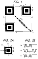
- Fig. 1 shows one embodiment of a two-dimensional code 1 in accordance with the present invention.
- This two-dimensional code 1 is a square having four apexes at its corners and comprises three isolated positioning symbols 2,2,2 placed at three corners of the two-dimensional code 1, a data region 3, a series of timing cells 4 diagonally extending in the data region 3, and an apex detecting cell 5 located at the remaining corner of the two-dimensional code 1.
- This two-dimensional code 1, a square code is constituted by the same number of vertical and lateral cells (21 cells x 21 cells). Each cell is the one selected from optically discriminable two kinds of cells, which are white (light) and black (dark) cells in the drawings and explanation in this embodiment.
- the timing cells 4 correspond to 1/1 inclined alternating light-and-dark cells.
- the apex detecting cell 5 acts as one of timing cells 4.
- Fig. 1 shows a blank condition where no data is described in the data region 3.
- the positioning symbols 2,2,2 are disposed at three of four corners of the two-dimensional code 1.
- the light and dark arrangement of cells in each positioning symbol 2 is characterized by a pattern consisting of a large square 2a of black cells, a middle square 2b of white cells concentric with but smaller in size than the large square 2a, and a small square 2c of black cells concentric with but smaller in size than the middle square 2b.
- Fig. 2 shows the scanning operation of this positioning symbol 2 and resultant light and dark signals.
- Fig. 2A shows representative three straight scanning lines (a),(b) and (c), each passing through the center of the positioning symbol with a distinctive angle.
- Fig. 2B shows signal waveforms corresponding to the light and dark patterns detectable along each of the scanning lines (a), (b) and (c), each frequency component ratio of which is identical with each other. More specifically, the frequency component ratio obtainable from each of the scanning lines (a), (b) and (c) passing through the center of the positioning symbol 2 is as follows:
- the characteristic frequency component ratio of the positioning symbol 2 is easily detectable by executing only one scanning operation in a predetermined direction. In other words, it is not necessary to repeatedly execute the scanning operation by changing the angle of the straight scanning line until the predesignated pattern is detected. Accordingly, the central position of the positioning symbol 2 can be easily and quickly found. Thus, the position of the two-dimensional code 1 is promptly identified, and the succeeding processing can be started immediately.
- the positioning symbol can be identified by only one scanning operation, it is no longer necessary to repeatedly change the angle of scan for making a judgement of whether the image taken from an image pickup device such as a TV camera includes various noises other than the two-dimensional code 1. Hence, the position of the two-dimensional code 1 is immediately recognized. In addition, all the necessary things to do after that is only to search the vicinity of thus found positioning symbol 2. Therefore, the code in the data region is speedily read out. Moreover, the means for detecting the specific frequency component ratio fits the hardware processing, which is executable in parallel with the image take-in processing by means of the TV camera etc. It means that the speed of reading out the code can be further increased.
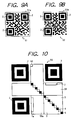
- FIG. 3 is a simple method of obtaining the contour of the two-dimensional code, realized by providing more than two positioning symbols 2 at corners of the code.
- Fig. 3A shows one example of a two-dimensional code 8 whose three corners are respectively provided a positioning symbol 2. If the central position of each of three positioning symbols 2, 2, 2 is found, it is possible to calculate the coordinates of three apexes of the two-dimensional code 8 based on the coordinates of the centers of the positioning symbols. Assuming that (x 0 , y 0 ), (x 1 , y 1 ) and (x 2 , y 2 ) represent the coordinates of the three apexes, the following equations 1 and 2 will obtain the coordinates (X 0 , Y 0 ) of the remaining apex. Thus, the contour of the two-dimensional code 8 is recognized.
- apex detecting cell 5 on an apex where the positioning symbol 2 is not disposed.
- the search will be conducted in the vicinity of the apex (X 0 , Y 0 ) obtained from the equations 1 and 2, to find out the apex detecting cell 5.
- the coordinates of the apex detecting cell 5 thus obtained as accurate apex coordinates (X 0 , Y 0 )
- the contour of the two-dimensional code is precisely obtained even if the two-dimensional code is unwantedly distorted. Needless to say, such an apex detecting cell 5 can be omitted if no distortion is expected.
- Fig. 3B shows an another two-dimensional code 9 in accordance with the present invention, which is characterized by two positioning symbols 2, 2 disposed at diagonal two corners of the two-dimensional code 9, whereas the two-dimensional code 8 of Fig. 3A includes three positioning symbols 2--2 disposed at three corners thereof. It will be preferable to additionally provide the apex detecting cell 5 in case of presence of distortion.
- the contour and an inclination ⁇ 2 of the two-dimensional code 9 are obtained from the following equations 4-8.
- a merit brought by this example is that the data ratio is increased.
- an orientation determining symbol 11 will be additionally required to determine the actual rotational position of the two-dimensional code 9.
- X 1 x 0 + x 2 - y 2 + y 0 2
- Y 1 y 0 + y 2 - x 0 + x 2 2
- X 3 x 0 + x 2 - y 0 + y 2 2
- Fig. 3C shows a two-dimensional code 13 in accordance with the present invention, which includes positioning symbols 2 disposed every corners of the two-dimensional code 13.
- This example is advantageous in that the contour of two dimensional code 13 is directly obtained even if the two-dimensional code 13 includes a significant distortion.
- An inclination ⁇ 3 is obtained from the definition tan -1 ( y 1 -y 0 /x 1 -x 0 ) .
- the data ratio is decreased.
- positioning symbols are disposed at all the corners, it is difficult to recognize the orientation of the code 13. For this reason, it is necessary to provide the orientation determining symbol 11 for identifying the orientation of the code 13.
- the timing cells 4, being alternating light and dark cells as shown in Fig. 1, have an arrangement of disposing white cells 4a and black cells 4b alternately so as to diagonally extend from one apex 1a of the two-dimensional code 1. That is, the timing cells 4 are arrayed with a 1/1 inclination (i.e. 45° inclination) in the data region 3 of the two-dimensional code 1.
- These timing cells 4--4 are used for accurately detecting the coordinates of each data cell. In other words, the density of image data is determined in accordance with intervals of these timing cells 4--4.
- Figs. 4A and 4B show representative arrangements of the timing cells 4.
- the timing cells 4 disclosed in Fig. 4A are arrayed diagonally from one apex P1 to the other apex P3 in such a manner that light and dark cells 4a and 4b are placed in an alternating manner so as to extend from the left top to the right bottom.
- the coordinates of each data cell in the data region 3 can be obtained using these timing cells 4.
- the coordinates of the center of each timing cell 4 is obtained.
- virtual lines i and j are drawn from the centers of timing cells 4 in vertical and lateral directions, each line being parallel to either side L1 or L2 of the two-dimensional code.
- the virtual lines i--i are laterally extending so as to pass through the coordinates of the centers of the timing cells 4--4, while the other virtual lines j--j are vertically extending so as to pass through the coordinates of the centers of the timing cells 4--4. Intersecting points formed by these virtual lines i--i and j--j are regarded as coordinates of each of data cells 4--4.
- the above-described method of obtaining the coordinates of each data cell using the timing cells 4 is advantageous in that error and affection of code distortion can be eliminated. Thus, the accuracy can be increased in the reading operation.
- Fig. 18 shows a conventional arrangement of the timing cells 4--4 which are disposed along two adjacent sides of the two-dimensional code.
- the number of timing cells 4 required for a 9x9 matrix is 17.
- the 9x9 matrix disclosed in Fig. 4A requires only 9 cells. In other words, the number of cells other than data cells can be reduced; therefore, the data ratio of two-dimensional code can be increased.
- the timing cells 4 can be diagonally arrayed from an intermediate portion of a side of the code.
- a series of timing cells 4 arrayed with an 1/1 inclination from an apex P13 can form intersecting points of virtual lines in the region R1, although the remaining region R2 has no intersecting points of virtual lines since it is only given one kind virtual lines (i.e. vertical lines only). It is of course possible to determine the coordinates of data cells in the region R2 based on these one kind virtual lines only. However, it is useful to provide another series of timing cells 4y in the region R2 for additionally forming lateral virtual lines, so that the coordinates of all the cells in the data region can be accurately identified.
- the data region 3 includes two protruding regions 3a and 3b where only one kind virtual lines (i.e. either vertical lines or lateral lines) are drawn.
- the area of such a protruding region is so small that accuracy is sufficiently assured without causing substantial problems.
- the protruding regions 3a and 3b are sandwiched between positioning symbols 2 and 2; therefore, it is technically possible to obtain intersecting points in such regions by drawing the other kind of virtual lines from each positioning symbol 2 based on light and dark pattern thereof. Thus, the coordinates are further accurately obtained.
- the data described in the data region 3 is generally encoded together with an error-correcting code restorable when it is contaminated by stain or the like and a CRC code for detecting an error.
- an error-correcting code restorable when it is contaminated by stain or the like
- a CRC code for detecting an error.
- burst error-correcting codes are suitable for stain or damage of the code.
- a Reed Solomon code is well known since it has an excellent error correcting efficiency.
- each character encoded by this kind of burst error-correcting code (which is expressed by a plurality of bits) is placed in the data cell region.
- Fig. 5 shows one example of such placement of a character. It is preferable that the cells 6a, each corresponding to a bit constituting part of a character, are summarized in a shape similar to a square without being dispersed.
- the example of Fig. 5 shows a group of nine cells (b0-b8) including eight bits dedicated to data of character and one bit dedicated to the parity.
- Figs. 6A and 6B illustrate the difference between a square (i.e. a two-dimensional) cell group and a linearly arrayed (i.e. a one- dimensional) cell group respectively representing a character, in order to explain that a two-dimensional code 21 including 3x3 square cell groups 6--6 is superior to a two-dimensional code 23 including 9 linearly arrayed cell groups 6--6 in view of readability under the presence of stain. More specifically, Fig. 6A shows a condition that a circular stain 16 adheres on the two-dimensional code 21 which consists of 3x3 square cell groups 6--6 each representing a character. In this case, the stain 16 is illustrated in a maximum size capable of suppressing the number of spoiled characters to be equal to only four. Fig.
- FIG. 6B shows a condition that another circular stain 16 is attached on the two-dimensional code 23 which consists of 9 linearly arrayed cell groups 6--6 piled up successively each representing a character.
- the stain 16 is illustrated in a maximum size capable of suppressing the number of spoiled characters to be equal to only four.
- a piece of stain 16a shown in Fig. 6C gives the same affection to the character cell groups 6--6 as that of a circular stain 16 having a diameter D. Accordingly, when the overall shape of the character cell groups 6--6 is arranged into a square (3 cells x 3 cells), the maximum diameter of the stain 16 only spoiling four character cell groups 6--6 is identical with the length of six consecutive cells as shown in Fig. 6A. On the other hand, when each character cell group 6 is arranged in a linear shape (1 cell x 9 cells), the maximum diameter of the stain 16 spoiling only four character cell groups 6--6 is identical with the length of four consecutive cells as shown in Fig. 6B.
- each character cell group 6 is advantageous in suppressing the number of spoiled characters as less as possible when the adverse affection by stain or damage is inevitable.
- the characters enter in an error-correcting region and easily read.
- data of each character are allocated in the cells within the data region 3.
- a predetermined character format either white or black is assigned to each cell 6a in each character cell group 6, thereby completing the pattern of the two-dimensional code 1.
- Fig. 7A shows a general binary encoding circuit using a comparator 30, which is speedy in operation and can respond to the change of brightness of the background.
- a follow-up waveform 32 approaches either a white or a black level of the input waveform 31 as shown in Fig. 7B when white cells or black cells are so consecutively and extensively arrayed.
- a resultant binary-encoded signal 33 has a width wider or narrower than the actual cell width.
- One is to provide dummy cells in the data region 3 and the character cell group 6 so as to be flexibly assigned to white or black depending upon the conditions.
- the other is to totally change the features of the cells according to a predetermined rule after white and black cells are placed in the data region 3. Either way will be practically adaptable, although the former method is disadvantageous in that the data ratio is lowered for provision of dummy cells.
- Fig. 8 shows, at upper left, a provisional two-dimensional code 41 including temporarily disposed data, and also shows, at upper center and right, two cell-feature-conversion matrix patterns 42a and 42b which are formed based on random number and certain regularity for changing cell features.
- the provisional two-dimensional code 41 is combined with each of the cell-feature-conversion matrix patterns 42a and 42b. More specifically, each cell on the provisional two-dimensional code 41 is reversed when its corresponding cell is a black cell 43a on the combined cell-feature-conversion matrix pattern 42a or 42b, while the features of the cell is not changed when its corresponding cell is a white cell 43b on the combined cell-feature-conversion matrix pattern 42a or 42b.
- the resultant pattern obtained from the above combination is identical with an exclusive-OR taken by the provisional two-dimensional code 41 and the cell-feature-conversion matrix pattern 42a or 42b.
- the above-described processing is executed with respect each of all the matrix patterns 42 prepared.
- a plurality of converted patterns 45 are obtained as much as the number of cell-feature-conversion matrix patterns prepared.
- a judgement is made as to whether white or black cells are arrayed consecutively and extensively and as to whether there happen to be a group of data cells having the same or similar frequency component ratio as that of the positioning symbol 2. From the result of this judgement, the most preferable data (i.e. an optimum placement pattern) is determined, thereby obtaining a finalized two-dimensional code 46.
- the left-hand pattern 45a is selected as an optimum placement pattern among plural patterns 45. By the way, this processing is only applied to the data region 3.
- two-dimensional code 46 Decoding operation of two-dimensional code 46 will be immediately carried out if the number of the cell-feature-conversion matrix patterns 42 is only one. However, when a plurality of matrix patterns 42 are used as described above, it is definitely necessary to find out the cell-feature-conversion matrix pattern 42 used for creating the finalized two-dimensional code 46. Thus, it is useful that the two-dimensional code 46 stores an information data 47 indicating the type of the conversion matrix pattern 42 used in the conversion processing for obtaining the two-dimensional code 46. If such an information data 47 is included, the data cells can be easily converted or reconstructed into their original pattern by taking an exclusive-OR between the corresponding cell-feature-conversion matrix pattern 42 and the two-dimensional code 46.
- Fig. 9A shows an example of dummy black line 51a surrounding all the outer periphery of the two-dimensional code 51, so that the binary-encoding operation for the positioning symbols 2--2 and outer peripheral data cells of the two-dimensional code 51 can be accurately carried out.
- the outer periphery of the two-dimensional code is a margin; therefore, it is feared that the outermost black cells in the positioning symbol 2 and the black data cells on the outer periphery cannot be accurately binary encoded as previously explained with reference to Fig. 7.
- surrounding the outer periphery of the two-dimensional code 51 by the dummy black line 51a is useful to increase the accuracy in the binary-encoding operation of the black cells in the positioning symbols 2 and in the outer peripheral region.
- the positioning symbols 2 are specially important for identifying the position of the matrix; therefore, it is preferable to provide dummy black lines 52a dedicated only to each positioning symbol 2 as shown in Fig. 9B, so that at least the frequency component of each positioning symbol is accurately detected and precisely binary encoded.
- the reading operation is easily disabled by simply drawing a line 131 across a bar code 130 as shown in Fig. 19.
- the length of a required nullifying line will be fairly long due to its two-dimensional arrangement. If the error-correcting code is involved as described above, drawing such a line is no longer effective to completely disable the two-dimensional code.
- a code-reading-prohibition cell 58 in the two-dimensional code 55.
- a reading device is prohibited to execute a reading operation. That is, the code-reading-prohibition cell 58 is checked prior to the decoding operation, and the decoding operation is prohibited when the cell 58 is black.
- the two-dimensional code 55 may include an important information 59 or a cell-feature-conversion matrix pattern information 7.
- an important information 59 or a cell-feature-conversion matrix pattern information 7 In view of adverse affection by stain, damage or brightness change of the background, it is preferable to dispose the same information 59a and 7a at different positions spaced from these information 59 and 7.
- this arrangement allows the reading device to read at least the other information (i.e. non-spoiled one), thereby assuring the reading operation of the important information 59 or 59a and the cell-feature-conversion matrix pattern information 7 or 7a.
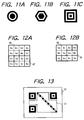
- the positioning symbol 2 can be constituted by concentric circles as shown in Fig. 11A, or concentric hexagons as shown in Fig. 11B, or any other concentric polygons.
- any concentric similar figures overlapped successively can be used as positioning symbol 2.
- the similar figures can be overlapped more as shown in Fig. 11C.
- the two-dimensional code 1 having a square contour
- the square contour can be replaced by a rectangular contour.
- a laterally elongated shape will be generally preferable as shown by a two-dimensional code 71 in Fig. 13, since such a shape well meets the lateral and vertical resolutions.
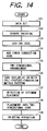
- Step 101 data are set in a work memory (Step 101). Then, objective data are binary encoded into "0" or “1” to form a two-dimensional code (Step 102). Subsequently, an error detecting code (CRC) and an error-correcting code are attached to the data (Steps 103 and 104) . Thereafter, these data are arranged in a two-dimensional pattern according to a predetermined rude (Step 105). Next, an exclusive-OR is taken by the resultant data pattern and each of cell-feature-conversion matrix patterns prepared beforehand (Step 106). Then, an optimum placement pattern is selected among resultant patterns (Step 107). After that, the optimum placement pattern is placed in the two-dimensional code (Step 108). Then, the printing operation is executed (Step 109).
- CRC error detecting code
- Step 105 an exclusive-OR is taken by the resultant data pattern and each of cell-feature-conversion matrix patterns prepared beforehand
- Step 106 an optimum placement pattern is selected among resultant patterns
- a CCD camera 500a takes an image of cells in a two-dimensional code 81, then converts the image into analog or digital signals pixel by pixel in response to light intensity of the image, and successively outputting resultant image signals.
- the pixel corresponds to each cell of the two-dimensional code 81.
- a decoder 500 comprising a CPU, a ROM, a RAM and an I/O unit, decodes the image signals of the two-dimensional code 81 into binary-coded signals, as shown in Fig. 17.
- the image signals produced from the CCD camera 500a are binary encoded (Step 300) in accordance with a level of each signal, thereby successively producing binary-coded signals.
- the binary-coded image signals are successively stored into a memory (RAM) as an image data every pixel through a hardware processing (Step 310).
- the coordinates of the positioning symbols 2 are detected based on the binary-coded image signals (Step 320). Namely, the specific pattern (i.e. the frequency component ratio of Fig. 2B) corresponding to the positioning symbol 2 is searched based on the binary-coded signals.
- Step 330 a judgement is made as to whether more than three positioning symbols 2--2 are found or not. Namely, the coordinates of each symbol 2 is obtained from the image data stored in the memory means (RAM) based on the detection of the specific pattern (Fig. 2B). The procedure of this flow chart does not proceed to the next step unless it completely detects all of three positioning symbols 2--2 of the two-dimensional code 81. Accordingly, when three positioning symbols are not found, the procedure returns to the step 300 to repeat the reading operation of image again. It may happen that a total of four positioning symbols 2--2 are detected at a time. This is believed that a confusing pattern having exactly the same frequency component ratio as that of the positioning symbol 2 exists in the data region of the two-dimensional code 81 or in a region outside the two-dimensional code 81.
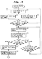
- Step 340 three of thus found positioning symbols 2--2, although they are mere candidates of positioning symbols 2--2 at this moment, are selected (Step 340). Then, the coordinates of an apex having no positioning symbol 2 is calculated (Step 350). Thereafter, a judgement is made as to whether the apex detecting cell 5 is found at the position obtained in the step 350 (Step 360) . If the apex detecting cell 5 is not detected, it is considered that selection and combination were improper. Thus, the next judgement is made as to whether there is another possible combination of the positioning symbols 2--2 (Step 370). If the answer is YES, the procedure returns to the step 340 to change the combination of the positioning symbols 2--2. If the apex detecting cell 5 is not found (i.e. "NO" in the step 370) as a result of repetitive detections based on any possible selection and combination, then the procedure returns to the step 300 to restart the binary-encoding processing of the image signals.
- the coordinates of a center of each timing cell 4 are obtained by detecting the alternately extending light and dark timing cells 4--4 one after another along a diagonal from the apex detecting cell 5 (Step 380). Then, virtual lines are drawn from the centers of these timing cells 4--4, thereby obtaining the coordinates of a center of each data cell (Step 390).
- a white-and-black pattern of the data cells is judged based on the image data (step 400).
- the cell-feature-conversion matrix pattern information 7 is read (Step 410). More specifically, the cell-feature-conversion matrix pattern is read out from the ROM, RAM or an external memory device not shown. Subsequently, an exclusive-OR is taken between thus readout conversion matrix pattern and the data cell pattern judged in the step 400, thereby restoring the content of the data cells (Step 420).
- steps 410 and 420 can be omitted when the cell features of the two-dimensional code is not converted.
- Step 430 the data region is divided into individual character cell groups. It is needless to say that division is executed in accordance with the placement of character cell groups as shown in Figs. 6A and 6B or Figs. 12A and 12B.
- Step 440 Individual data involved in each character cell group are converted into a corresponding character.
- Step 450 a judgement is made as to whether error is detected based on the error-correcting code. If any error is found, the error correction of data is executed (Step 460). When no error is found in the step 450 or after the error correction of data is finished, another judgement is made as to whether any error is found based on the error detecting code (i.e. CRC code) (Step 470). If no error is found, the procedure is terminated. If any error is found, the procedure returns to the step 300 to restart all the processing from the beginning.
- CRC code error detecting code
- the resultant data are transmitted to a host computer (not shown) wherein a predetermined control is executed based on these data.
- the positioning symbol assures the same characteristic frequency component ratio to be obtained irrespective of the orientation of a straight scanning line. Hence, it is not necessary to repeat the scanning operation changing its scanning angle.
- the matrix at least two predetermined positions are quickly and easily detected. Once the positions of the predetermined two positions are detected in the matrix, the position and a rotational angle of the whole matrix is easily calculated based on the distance and angle between them.
- the predetermined positions When the predetermined positions are apexes of the matrix, they will be immediately found in the scanning search, and are seldom disturbed by other code patterns when they are searched.
- the shape of the matrix is generally a square or a rectangle.
- a preferable shape of the positioning symbol is a square or a rectangle since it fits to the shape of the matrix and loss of space can be suppressed at a minimum level.
- a square is most preferable since it assures a least loss.
- the matrix includes a series of light and dark cells alternately extending with an inclination 1/1, the number of cells used for the alternating light-and-dark cells can be fairly reduced. Thus, the remaining cells can be effectively used for a space available for other useful information.
- the data cells can be converted into a pattern discriminable from the characteristic patterns of the positioning symbols and the 1/1 inclined alternating light-and-dark cells. It will facilitate the discrimination of the data cells from the positioning symbols and the 1/1 inclined alternating light-and-dark cells.
- the processing will become simple and speedy.
Claims (10)
- Zweidimensionaler Code mit:Zellen (b0-b8), welche jeweils binär kodierte Daten darstellen,
wobei die Zellen auf einer zweidimensionalen Matrix (1) als Muster plaziert sind, welches durch eine Abtastoperation entlang einer vorbestimmten Abtastlinie lesbar ist; dadurch gekennzeichnet, dasswenigstens zwei Positionierungssymbole (2) an vorbestimmten Positionen in der Matrix angeordnet sind, wobei jedes der Positionierungssymbole (2) ein Muster aufweist, welches zum Erzeugen einer Wellenform mit einem identischen Elementebreitenverhältnis unabhängig von irgendeiner Ausrichtung der Abtastlinie geeignet ist, wenn die Abtastlinie durch die Mitte jedes Positionierungssymbols hindurchtritt. - Zweidimensionaler Code nach Anspruch 1, dadurch gekennzeichnet, dass die vorbestimmten Positionen Gipfelpunkte der zweidimensionalen Matrix (1) sind.
- Zweidimensionaler Code nach Anspruch 1 oder 2, dadurch gekennzeichnet, dass jedes Positionierungssymbol ein Muster aufweist, welches ähnliche konzentrische Figuren (2a, 2b und 2c) von einer sich verringernden Größe enthält, die aufeinanderfolgend überlappt sind.
- Zweidimensionaler Code nach Anspruch 1, des weiteren gekennzeichnet durch eine Reihe von Timing-Zellen (4), welche abwechselnd helle und dunkle Zellen (4a und 4b) enthalten, wobei die Reihe eine Neigung von 45° in der zweidimemsionalen Matrix (1) aufweist.
- Zweidimensionaler Code nach Anspruch 1, dadurch gekennzeichnet, dass die binär codierten Daten eine Mehrzahl von Schriftzeichen (6) enthalten und jedes der Schriftzeichen durch eine Gruppe von Zellen (6a) dargestellt wird, welche in einem zweidimensionalen Gebiet (3) in der Matrix (1) angeordnet sind.
- Zweidimensionaler Code nach Anspruch 1, des weiteren gekennzeichnet durch eine Gipfelpunkterfassungszelle (5), welche auf einem Gipfelpunkt der zweidimensionalen Matrix (1) angeordnet ist, wo keines der Positionierungssymbole angeordnet ist.
- Zweidimensionales Codelesegerät zum optischen Lesen des in Anspruch 1 definierten zweidimensionalen Codes, mit:einem Bildaufnahmegerät (500a), welches ein Bild des zweidimensionalen Codes (81) aufnimmt, danach das Bild in Bildsignale, Pixel um Pixel, im Ansprechen auf die Lichtintensität des Bilds umwandelt und darauffolgend resultierende Bildsignale ausgibt;einer Decodereinheit (500), welche die resultierenden Bildsignale in binär kodierte Signale dekodiert;
wobei die Decodereinheit (500) aufweist:eine binäre Kodiereinrichtung (CPU; Schritt 300), welche die Bildsignale entsprechend einem Pegel von jedem Signal binär kodiert und die binär kodierten Signale aufeinanderfolgend ausgibt;eine Speichereinrichtung (RAM), welcher die binär kodierten Signale als Bilddaten entsprechend einer Position eines Pixels speichert, wo das Bild aufgenommen worden ist;eine Symbolerfassungseinrichtung (CPU; Schritt 320), welche das spezifische Muster entsprechend jedem der Positionierungssymbole (2) auf der Grundlage der binär kodierten Signale erfasst und die Koordinaten von jedem der Symbole (2) von den in der Speichereinrichtung (RAM) gespeicherten Bilddaten auf der Grundlage des erfassten spezifischen Musters erfasst;eine Matrixpositionsbestimmungseinrichtung (CPU; Schritte 340-390), welche eine Kontur und eine Ausrichtung der zweidimensionalen Matrix auf der Grundlage der Koordinaten der von der Symbolerfassungseinrichtung erfassten Symbole (2) vollendet, wodurch alle Koordinaten der binär kodierten Zellen identifiziert werden, welche auf der zweidimensionalen Matrix plaziert sind; undeine Leseeinrichtung (CPU; Schritt 400-470), welche die in der Speichereinrichtung (RAM) gespeicherten Bilddaten entsprechend der vollendeten Kontur und Ausrichtung der zweidimensionalen Matrix ausliest. - Zweidimensionales Codelesegerät nach Anspruch 7, dadurch gekennzeichnet, dassder zweidimensionale Code (81) eine Reihe von Timing-Zellen (4) aufweist, welche abwechselnd helle und dunkle Zellen (4a und 4b) enthalten, die in der Matrix (1) angeordnet und durch das Bildaufnahmegerät (500a) optisch lesbar sind; unddie Decodereinheit (5) des weiteren eine Timing-Zellenerfassungseinrichtung (CPU; Schritt 380) aufweist, welche Koordinaten jeder Timing-Zelle (4) von den in der Speichereinrichtung (RAM) gespeicherten Bilddaten entsprechend den Koordinaten der durch die Symbolerfassungseinrichtung (CPU; Schritt 320) erlangten Symbole (2) erfasst, wobei die Timing-Zellen (4) die Dichte der Bilddaten entsprechend den Intervallen der Timing-Zellen bestimmen.
- Zweidimensionales Codelesegerät nach Anspruch 7, dadurch gekennzeichnet, dassder zweidimensionale Code (81) unter Durchführung einer exklusiven ODER-Operation, Zelle um Zelle, zwischen einem vorbestimmten provisorischen zweidimensionalen Code (41) und einem zweidimensionalen Zellenmerkmalumwandlungscode (42) erzeugt wird, welcher ein spezifisches Umwandlungsmuster enthält, das durch helle und dunkle Zellen entsprechend dem Datengebiet des provisorischen zweidimensionalen Codes (41) dargestellt wird; unddie Leseeinrichtung (CPU; Schritt 400-470) die Information des provisorischen zweidimensionalen Codes (42) unter Durchführung einer exklusiven ODER-Operation, Zelle um Zelle, zwischen den von der Bildaufnahmeeinrichtung (500a)) erlangten zweidimensionalen Bilddaten und den zweidimensionalen Bilddaten des in der Speichereinrichtung (RAM) gespeicherten zweidimensionalen Zellenmerkmalumwandlungscodes (42) wiederherstellt.
- Zweidimensionales Codeleseverfahren zum optischen Lesen des in Anspruch 1 definierten zweidimensionalen Codes, mit den Schritten:Aufnehmen eines Bilds des zweidimensionalen Codes (81) durch ein Bildaufnahmegerät (500a), danach Umwandeln des Bilds in Bildsignale, Pixel um Pixel, im Ansprechen auf die Lichtintensität des Bilds und binäres Kodieren (Schritt 300) der Bildsignale entsprechend einem Pegel jedes Signals, danach Speichern (Schritt 310) der derart binär kodierten Signale als Bilddaten in einer Speichereinrichtung (RAM) entsprechend einer Position eines Pixels, wo das Bild aufgenommen worden ist;Erfassen (Schritt 320) des spezifischen Musters entsprechend jedem der Positionierungssymbole (2) auf der Grundlage der binär kodierten Signale als Verarbeitung parallel zu dem Schritt (Schritt 310) des Speicherns der binär kodierten Signale in der Speichereinrichtung (RAM);Erfassen (Schritt 320) von Koordinaten jedes der Symbole (2) von den in der Speichereinrichtung (RAM) gespeicherten Bilddaten auf der Grundlage der Erfassung des spezifischen Musters;Vollenden (Schritte 340-390) einer Kontur und einer Orientierung der zweidimensionalen Matrix auf der Grundlage der Koordinaten der Symbole (2), wodurch alle Koordinaten der binär kodierten Zellen identifiziert werden, welche auf der zweidimensionalen Matrix plaziert sind; undAuslesen (Schritt 400-470) der in der Speichereinrichtung (RAM) gespeicherten Bilddaten entsprechend der vollendeten Kontur und Ausrichtung der zweidimensionalen Matrix.
Applications Claiming Priority (3)
| Application Number | Priority Date | Filing Date | Title |
|---|---|---|---|
| JP42587/94 | 1994-03-14 | ||
| JP4258794A JP2938338B2 (ja) | 1994-03-14 | 1994-03-14 | 二次元コード |
| JP4258794 | 1994-03-14 |
Publications (2)
| Publication Number | Publication Date |
|---|---|
| EP0672994A1 EP0672994A1 (de) | 1995-09-20 |
| EP0672994B1 true EP0672994B1 (de) | 2000-07-26 |
Family
ID=12640203
Family Applications (1)
| Application Number | Title | Priority Date | Filing Date |
|---|---|---|---|
| EP95103511A Expired - Lifetime EP0672994B1 (de) | 1994-03-14 | 1995-03-10 | Verfahren und Vorrichtung zum Lesen eines optischen zweidimensionalen Kodes |
Country Status (3)
| Country | Link |
|---|---|
| EP (1) | EP0672994B1 (de) |
| JP (1) | JP2938338B2 (de) |
| DE (1) | DE69518098T2 (de) |
Cited By (10)
| Publication number | Priority date | Publication date | Assignee | Title |
|---|---|---|---|---|
| WO2005096219A1 (en) * | 2004-04-02 | 2005-10-13 | Silverbrook Research Pty Ltd | Surface having disposed therein or thereon coded data |
| WO2013100851A2 (en) | 2011-12-29 | 2013-07-04 | Delaval Holding Ab | Pairing of a mobile terminal with a farm control and monitoring system |
| EP2701099A1 (de) | 2012-08-24 | 2014-02-26 | I4pack GmbH | Computernetzwerk zur dynamischen Kontrolle von QR-Codes |
| WO2014074057A1 (en) | 2012-11-07 | 2014-05-15 | Delaval Holding Ab | Methods, arrangements and devices for animal management |
| EP2782060A1 (de) | 2013-03-19 | 2014-09-24 | Usual Q Smart S.L. | Kaufverfahren und System zum Einkaufen mittels zweidimensionaler grafischer Codes |
| US9355293B2 (en) | 2008-12-22 | 2016-05-31 | Canon Kabushiki Kaisha | Code detection and decoding system |
| DE102016200388A1 (de) | 2016-01-14 | 2017-07-20 | Tridonic Gmbh & Co Kg | System zur Erzeugung von Positionsinformation, entsprechendes Verfahren sowie mobile Vorrichtung und Server zur Erzeugung von Positionsinformation |
| WO2017144291A1 (de) | 2016-02-26 | 2017-08-31 | Robert Bosch Gmbh | System und verfahren zum lokalisieren |
| EP3242252A1 (de) | 2016-05-06 | 2017-11-08 | Doris Renate Purzer | Mehrdimensionale grafische codes |
| WO2023174799A1 (de) | 2022-03-16 | 2023-09-21 | Dataqon Gmbh | Dienstleister-kunden-kommunikationssystem mit zentraler datenspeicherung und -verwaltung, integriertem-synchronisiertem zeiterfassungssystem sowie lokalen terminals |
Families Citing this family (119)
| Publication number | Priority date | Publication date | Assignee | Title |
|---|---|---|---|---|
| JP3568374B2 (ja) * | 1992-09-28 | 2004-09-22 | オリンパス株式会社 | ドットコード及び情報再生システム |
| WO1994008314A1 (en) * | 1992-09-28 | 1994-04-14 | Olympus Optical Co., Ltd. | Dot code and information recording/reproducing system for recording/reproducing dot code |
| JP2867904B2 (ja) * | 1994-12-26 | 1999-03-10 | 株式会社デンソー | 2次元コード読取装置 |
| JP3448120B2 (ja) | 1994-12-27 | 2003-09-16 | シャープ株式会社 | デジタル情報記録担体 |
| JP3668275B2 (ja) * | 1995-03-15 | 2005-07-06 | シャープ株式会社 | デジタル情報記録方法、解読方法および解読装置 |
| JP3655661B2 (ja) * | 1995-03-31 | 2005-06-02 | シャープ株式会社 | デジタル情報記録担体及びそれを用いたデジタル情報読み取り方法 |
| US5862270A (en) * | 1995-12-08 | 1999-01-19 | Matsushita Electric Industrial Co., Ltd. | Clock free two-dimensional barcode and method for printing and reading the same |
| JP3209108B2 (ja) * | 1996-08-23 | 2001-09-17 | 松下電器産業株式会社 | 2次元コード読み取り装置 |
| JPH10326331A (ja) | 1997-03-24 | 1998-12-08 | Olympus Optical Co Ltd | ドットコードを有する記録媒体及びコード読取装置 |
| US6267296B1 (en) | 1998-05-12 | 2001-07-31 | Denso Corporation | Two-dimensional code and method of optically reading the same |
| US6201901B1 (en) * | 1998-06-01 | 2001-03-13 | Matsushita Electronic Industrial Co., Ltd. | Border-less clock free two-dimensional barcode and method for printing and reading the same |
| JP4122629B2 (ja) | 1998-09-03 | 2008-07-23 | 株式会社デンソー | 2次元コードの生成方法 |
| JP3458737B2 (ja) | 1998-11-27 | 2003-10-20 | 株式会社デンソー | 2次元コードの読取方法及び記録媒体 |
| US6601772B1 (en) | 2000-07-14 | 2003-08-05 | Intellidot Corporation | Compact matrix code and one-touch device and method for code reading |
| US6722567B2 (en) | 2001-06-07 | 2004-04-20 | Hewlett-Packard Development Company, L.P. | Generating and decoding graphical bar codes |
| US7082225B2 (en) | 2001-08-28 | 2006-07-25 | Nippon Telegraph And Telephone Corporation | Two dimensional image recording and reproducing scheme using similarity distribution |
| DE10220220C1 (de) * | 2002-02-18 | 2003-05-22 | Tropf Hermann | Lokalisierungsmuster für automatisch lesbare Codes und für Klarschrift, sowie Codierung von Klarschrift |
| JP4208481B2 (ja) * | 2002-04-30 | 2009-01-14 | トッパン・フォームズ株式会社 | 2次元コード読取方法および2次元コード読取システム並びにこれらに使用される2次元コードが付された物品 |
| KR100414524B1 (ko) * | 2002-10-31 | 2004-01-16 | 주식회사 아이콘랩 | 복호 특성이 우수하며 단계별 에러레벨조정이 가능한2차원 코드 및 그 코드의 인코딩 디코딩 방법 |
| EP1615420B1 (de) | 2003-04-15 | 2009-08-19 | Fujitsu Limited | Codeerkennungsverfahren und einrichtung |
| WO2004097717A1 (ja) | 2003-05-02 | 2004-11-11 | Yutaka Kiuchi | 2次元コード読取方法、表示方法、および実行プログラム |
| JP4180497B2 (ja) | 2003-12-05 | 2008-11-12 | 富士通株式会社 | コード種類判別方法、およびコード境界検出方法 |
| WO2005066884A1 (ja) * | 2003-12-26 | 2005-07-21 | Wireaction Inc. | 2次元バーコードシステム、2次元バーコード生成方法およびコンピュータプログラム |
| JP4576146B2 (ja) | 2004-04-02 | 2010-11-04 | 富士通株式会社 | 特定画像位置推定装置 |
| JP2005316755A (ja) * | 2004-04-28 | 2005-11-10 | Nec Electronics Corp | 2次元矩形コードシンボル読み取り装置及び2次元矩形コードシンボル読み取り方法 |
| ATE497219T1 (de) | 2004-10-15 | 2011-02-15 | Sony Computer Entertainment Inc | Karte und bilddatenübertragungsverfahren |
| DE602005007571D1 (de) * | 2005-02-25 | 2008-07-31 | Psion Teklogix Systems Inc | Automatische Detektion und Korrektur von Perspektivenverzerrung für Dokumentabbildungen |
| JP4088300B2 (ja) | 2005-06-01 | 2008-05-21 | 富士通株式会社 | 画像領域検出装置、画像領域検出方法および画像領域検出プログラム |
| JP4098313B2 (ja) | 2005-06-02 | 2008-06-11 | 富士通株式会社 | 画像処理装置 |
| US8511562B2 (en) | 2005-07-22 | 2013-08-20 | Content Idea Of Asia Co., Ltd. | Layered two-dimensional code, creation method thereof, and read method |
| JP2007066377A (ja) | 2005-08-30 | 2007-03-15 | Sony Corp | 記録装置、記録方法、ホログラム記録媒体 |
| KR100828539B1 (ko) | 2005-09-20 | 2008-05-13 | 후지제롯쿠스 가부시끼가이샤 | 이차원 코드의 검출 방법, 검출 장치, 및 검출 프로그램을기억한 기억 매체 |
| JP4665710B2 (ja) | 2005-10-21 | 2011-04-06 | 株式会社デンソーウェーブ | 情報コード担体 |
| JPWO2007072545A1 (ja) | 2005-12-20 | 2009-05-28 | テクニカルインフラロジック有限会社 | 情報認証ゲートウェイ、情報認証ゲートウェイを用いる情報取得システム及び情報取得方法 |
| JP4911340B2 (ja) | 2006-02-10 | 2012-04-04 | 富士ゼロックス株式会社 | 二次元コード検出システムおよび二次元コード検出プログラム |
| US8050502B2 (en) | 2006-06-21 | 2011-11-01 | Namco Bandai Games Inc. | Two-Dimensional code generation method, two-dimensional code, two-dimensional code recognition method, and image recognition device |
| WO2008053545A1 (fr) | 2006-10-31 | 2008-05-08 | Fujitsu Limited | Dispositif de chiffrage/déchiffrage d'images, procédé et programme |
| CN101589408B (zh) | 2007-01-23 | 2014-03-26 | 日本电气株式会社 | 标记生成及标记检测的系统、方法和程序 |
| WO2008134804A1 (en) * | 2007-05-03 | 2008-11-13 | Kevin Loughrey | Large number id tagging system |
| JP4348381B2 (ja) | 2007-05-30 | 2009-10-21 | 富士通株式会社 | 画像暗号化/復号化装置、方法およびプログラム |
| WO2008146390A1 (ja) | 2007-05-31 | 2008-12-04 | Pfu Limited | 紙媒体情報暗号化システム、復号システム、プログラムおよび方法 |
| US8948385B2 (en) | 2007-05-31 | 2015-02-03 | Pfu Limited | Electronic document encrypting system, decrypting system, program and method |
| US8542867B2 (en) | 2007-07-31 | 2013-09-24 | Canon Kabushiki Kaisha | Image processing for reproducing code image from original information |
| JP2009130725A (ja) * | 2007-11-26 | 2009-06-11 | Nippon Telegr & Teleph Corp <Ntt> | 可視光通信システムとその光受信装置 |
| JP5206024B2 (ja) | 2008-02-28 | 2013-06-12 | 富士通株式会社 | 画像復号化装置、画像暗号化装置、画像復号化方法および画像復号化プログラム |
| US8430329B2 (en) | 2008-03-14 | 2013-04-30 | Yutaka Kiuchi | Two-dimensional code publishing program and two-dimensional code decoding program |
| JP5071188B2 (ja) | 2008-03-24 | 2012-11-14 | 富士通株式会社 | 画像暗号化/復号化装置及びプログラム |
| JP5120156B2 (ja) | 2008-03-27 | 2013-01-16 | 株式会社デンソーウェーブ | 二次元コード |
| JP5136302B2 (ja) | 2008-03-27 | 2013-02-06 | 株式会社デンソーウェーブ | 二次元コード、二次元コード生成方法、二次元コードを表示させるコンピュータ読み取り可能なプログラム、二次元コードを利用した認証方法、及び二次元コードを利用した情報提供方法 |
| WO2009144796A1 (ja) | 2008-05-29 | 2009-12-03 | 株式会社Pfu | 電子ドキュメント処理システム、方法およびプログラム |
| JP5168124B2 (ja) * | 2008-12-18 | 2013-03-21 | 富士通株式会社 | 画像のマーカ付加装置、方法、及びプログラム |
| EP2410727B1 (de) | 2009-03-19 | 2017-08-09 | Fujitsu Limited | Markierungserzeugungsprogramm, wiederherstellungsprogramm, markierungserzeugungseinrichtung, wiederherstellungseinrichtung und markierungserzeugungsverfahren |
| JP5447235B2 (ja) | 2009-07-31 | 2014-03-19 | セイコーエプソン株式会社 | マーカー処理方法、マーカー処理装置、およびマーカー処理プログラム |
| JP5321352B2 (ja) | 2009-08-27 | 2013-10-23 | 富士ゼロックス株式会社 | 二次元コード生成装置、画像形成システム、二次元コード読み取り装置、コンピュータプログラム及び媒体 |
| JP5505007B2 (ja) | 2010-03-18 | 2014-05-28 | 富士通株式会社 | 画像処理装置、画像処理方法及び画像処理用コンピュータプログラム |
| JP5560887B2 (ja) | 2010-05-10 | 2014-07-30 | 富士ゼロックス株式会社 | 画像処理装置及び画像処理プログラム |
| JP5541360B2 (ja) | 2010-06-25 | 2014-07-09 | 富士通株式会社 | 画像処理装置および画像処理方法 |
| GB201014408D0 (en) * | 2010-08-31 | 2010-10-13 | Swipe Pay Ltd | Improvements in and relating to mobile communication devices |
| WO2012127578A1 (ja) | 2011-03-18 | 2012-09-27 | 富士通株式会社 | 画像処理装置、画像処理方法及び画像処理用コンピュータプログラム |
| WO2012127639A1 (ja) | 2011-03-22 | 2012-09-27 | 富士通株式会社 | 画像処理装置及び画像処理方法 |
| EP2751750A4 (de) * | 2011-08-30 | 2015-04-01 | Hewlett Packard Development Co | Identifizierung der benutzer-ziel-relation |
| GB2496415A (en) * | 2011-11-10 | 2013-05-15 | Skype | An image data decoding method for decoding contact information and communication event related to a second user and implementing the communication event |
| JP5586705B2 (ja) | 2012-07-05 | 2014-09-10 | 株式会社東芝 | オブジェクトにデータを埋め込む装置及び方法、並びに埋め込まれたデータを抽出する装置及び方法 |
| EP2765531B1 (de) * | 2012-08-17 | 2016-05-18 | A.T Communications Co., Ltd. | Vorrichtung zur authentifizierung zweidimensionaler codes, verfahren zur authentifizierung zweidimensionaler codes und programm |
| JP6137190B2 (ja) * | 2012-10-04 | 2017-05-31 | 新東工業株式会社 | 装置点検システム |
| JP6115750B2 (ja) * | 2012-10-25 | 2017-04-19 | 株式会社デンソーウェーブ | 画像認識システム、画像認識方法、及び携帯端末 |
| JP5743994B2 (ja) * | 2012-10-26 | 2015-07-01 | 東京書籍株式会社 | 二次元コードを表示した印刷物 |
| EP2921996B1 (de) * | 2012-11-13 | 2019-01-16 | Kyodo Printing Co., Ltd. | Zweidimensionaler code |
| EP2921997B1 (de) | 2012-11-13 | 2021-01-06 | Kyodo Printing Co., Ltd. | Zweidimensionaler code |
| JP5848464B2 (ja) | 2012-11-13 | 2016-01-27 | 共同印刷株式会社 | 二次元コード、二次元コードの作成システムおよび解析プログラム |
| ITAN20130029A1 (it) | 2013-02-15 | 2014-08-16 | Soundreflections Di Polzoni Andrea | Sistema e metodo per generare elementi contenenti codici quick response |
| WO2015001637A1 (ja) * | 2013-07-03 | 2015-01-08 | A・Tコミュニケーションズ株式会社 | 認証サーバ、認証システム、認証方法、及びプログラム |
| WO2015008102A1 (en) | 2013-07-19 | 2015-01-22 | Niss Group Sa | System and method for indentifying and authenticating a tag |
| JP6148976B2 (ja) * | 2013-12-18 | 2017-06-14 | 株式会社ミマキエンジニアリング | 境界決定方法およびメディア切断方法 |
| JP5984863B2 (ja) * | 2014-01-29 | 2016-09-06 | 京セラドキュメントソリューションズ株式会社 | 画像処理装置 |
| GB2523136A (en) * | 2014-02-13 | 2015-08-19 | Coolio Ltd | A method and apparatus for encoding and decoding digital data in an image |
| CN106462785B (zh) | 2014-05-14 | 2018-09-14 | 共同印刷株式会社 | 二维码以及二维码的分析系统 |
| WO2015174192A1 (ja) | 2014-05-14 | 2015-11-19 | 共同印刷株式会社 | 二次元コード、二次元コードの解析システム及び二次元コードの作成システム |
| JP6486016B2 (ja) * | 2014-05-16 | 2019-03-20 | 株式会社デンソーウェーブ | 情報コード生成方法、情報コード、及び情報コード利用システム |
| EP2975556A1 (de) | 2014-07-18 | 2016-01-20 | NISS Group SA | System und Verfahren zur Identifizierung und Authentifizierung von Munition |
| DE102015000135A1 (de) | 2015-01-07 | 2016-07-07 | Martin Eberlein | Verfahren zum Ausleihen eines für einen Einkaufsvorgang geeigneten Transportmittels sowie Transportmittel zur Durchführung dieses Verfahrens |
| DE102015002782A1 (de) | 2015-03-06 | 2016-09-08 | Grohe Ag | Sanitärarmatur mit Sensor |
| CN105117677B (zh) * | 2015-07-30 | 2017-10-31 | 福建联迪商用设备有限公司 | 一种qr码特征检测方法及系统 |
| US10046939B2 (en) | 2015-08-05 | 2018-08-14 | Horizon International Inc. | Sheet process apparatus and control method thereof |
| JP6233734B2 (ja) | 2015-09-01 | 2017-11-22 | 合同会社IP Bridge1号 | 読取装置、情報処理方法、情報処理装置、プログラム、記録媒体、インク、色素、及び記憶装置 |
| CN105095822B (zh) * | 2015-09-07 | 2018-07-06 | 福建联迪商用设备有限公司 | 一种汉信码特征图形检测方法及系统 |
| WO2017046967A1 (ja) * | 2015-09-15 | 2017-03-23 | 大日本印刷株式会社 | 情報保存装置および情報読出装置 |
| DE102015013001A1 (de) | 2015-10-07 | 2017-04-13 | Carsten Engel | Verfahren zur Verbindung analoger Objekte mit einer digitalen Speichereinheit |
| JP6927559B2 (ja) | 2015-12-17 | 2021-09-01 | 株式会社テララコード研究所 | 光学コード、光学コードの作成方法、光学コードの真贋判定方法、光学コードの読取装置、及び読取補助装置 |
| DE102015226684A1 (de) | 2015-12-23 | 2017-07-13 | 1112tag.com UG (haftungsbeschränkt) | Verfahren zum Zurverfügungstellen eines Zugriffs auf digitale Ressourcen auf einem Mobilgerät, sowie entsprechendes Computerprogrammprodukt, Mobilgerät, Server und Anordnung |
| JP6465051B2 (ja) | 2016-03-04 | 2019-02-06 | 株式会社デンソーウェーブ | 情報コードおよび情報コードの読取方法 |
| JP2018001333A (ja) * | 2016-06-30 | 2018-01-11 | セイコーエプソン株式会社 | 校正ボード、ロボット、及び検出方法 |
| MA39233B1 (fr) | 2016-07-27 | 2018-11-30 | Univ Abdelmalek Essaadi Tetouan | Procédé d'identification à distance du code qr au moyen d'une caméra. |
| DE102017006616A1 (de) | 2016-08-31 | 2018-03-01 | Sew-Eurodrive Gmbh & Co Kg | System zur Lageerfassung und Verfahren zur Lageerfassung |
| IT201700014359A1 (it) | 2017-02-09 | 2018-08-09 | Aitek S P A | Codice a barre anticontraffazione, sistema e metodo per la generazione e l’autenticazione di un titolo sulla base di detto codice |
| JP6880903B2 (ja) * | 2017-03-27 | 2021-06-02 | 横浜ゴム株式会社 | パンク修理液の有効期限通知装置及び方法 |
| JP2019021165A (ja) * | 2017-07-20 | 2019-02-07 | 株式会社デンソーウェーブ | 二次元コード及び二次元コード読取装置 |
| DE102017131239A1 (de) | 2017-12-22 | 2019-06-27 | Eckart Neuhaus | Zentrale Erfassung von klinischen und nicht-klinischen Messwerten in Krankenhaus, Altenheim und anderen Pflegeeinrichtungen |
| JP6473899B1 (ja) | 2017-12-29 | 2019-02-27 | 株式会社I・Pソリューションズ | 複合コードパターン、生成装置、読み取り装置、方法およびプログラム |
| DE102018200574A1 (de) | 2018-01-15 | 2019-07-18 | Zf Friedrichshafen Ag | Parksystem zur Detektion und Verwaltung von belegten und nicht belegten Parkständen |
| JP6435078B1 (ja) | 2018-03-08 | 2018-12-05 | mui Lab株式会社 | 二次元コードの表示方法及び表示装置 |
| JP6562136B2 (ja) * | 2018-08-02 | 2019-08-21 | 株式会社デンソーウェーブ | 情報コード生成方法、情報コード、及び情報コード利用システム |
| KR102219751B1 (ko) | 2019-01-21 | 2021-02-24 | 주식회사 머니브레인 | 블록체인에 기반하여 규격화된 패턴을 머클 트리 구조로 인증하는 방법 및 장치 |
| CN111507120A (zh) * | 2019-01-31 | 2020-08-07 | 北京骑胜科技有限公司 | 二维码定位框识别方法、装置、电子设备及存储介质 |
| DE102019202636B4 (de) | 2019-02-27 | 2023-11-16 | Zf Friedrichshafen Ag | Markierungsobjekt anordenbar an einen Fahrzeug-Kindersitz zum adaptiven Auslösen eines Aufprallkissens, Verfahren zum Bestimmen einer Position und/oder Ausrichtung eines Fahrzeug-Kindersitzes relativ zu einem Fahrzeugsitz und Computerprogrammprodukt zum adaptiven Auslösen eines Aufprallkissens |
| US11574330B2 (en) | 2019-04-26 | 2023-02-07 | Drum Technologies, Inc. | Distributed system to enable dynamic, on-demand sales force with merchant, seller and buyer networked |
| EP3731163A1 (de) * | 2019-04-26 | 2020-10-28 | Drum Technologies, Inc. | System und verfahren zur dynamischen bedarfsgerechten vertriebskraft und angebotsverbreitung |
| DE102020002676B3 (de) | 2020-05-05 | 2021-03-25 | Sew-Eurodrive Gmbh & Co Kg | Mobiles Transportsystem |
| IT202000013516A1 (it) | 2020-06-08 | 2021-12-08 | Mario Piccioni | Cassetta postale digitale con tecnologia biometrica |
| DE202020005824U1 (de) | 2020-06-17 | 2022-08-22 | Maximilian Knöfel | System zum Bereitstellen und Weitergeben von spezifischen Informationen einer Person und/oder einer Sache |
| DE102020115928A1 (de) | 2020-06-17 | 2021-12-23 | Maximilian Knöfel | System zum Bereitstellen und Weitergeben von spezifischen Informationen einer Person und/oder einer Sache |
| JP7351265B2 (ja) * | 2020-06-26 | 2023-09-27 | 株式会社豊田自動織機 | 認識装置及び認識方法 |
| DE102020125901A1 (de) | 2020-10-02 | 2022-04-07 | Nishi Notani | Biegsame Anzeigeeinheit mit elektronischem Papier und Solarfolie |
| DE102020129339A1 (de) | 2020-11-06 | 2022-05-12 | Windmöller & Hölscher Kg | Verfahren zum automatischen Fehlermanagement an einer Druckmaschine |
| CN112414225A (zh) * | 2020-11-13 | 2021-02-26 | 中国船舶重工集团公司第七0七研究所 | 一种二维码和圆形编码盘相结合的靶标及其识别方法 |
| DE102020132492A1 (de) | 2020-12-07 | 2022-06-09 | Windmöller & Hölscher Kg | Wickler zum Wickeln einer Materialbahn |
| CN113792564B (zh) * | 2021-09-29 | 2023-11-10 | 北京航空航天大学 | 基于不可见投影二维码的室内定位方法 |
| JP7026283B1 (ja) * | 2021-10-22 | 2022-02-25 | 敏男 松本 | 識別コード及びこれを用いた紙媒体文書電子化システム |
| WO2023078943A1 (de) | 2021-11-08 | 2023-05-11 | Sew-Eurodrive Gmbh & Co. Kg | Mobiles transportsystem |
Citations (1)
| Publication number | Priority date | Publication date | Assignee | Title |
|---|---|---|---|---|
| WO1993001566A2 (en) * | 1991-07-11 | 1993-01-21 | United Parcel Service Of America, Inc. | System and method for acquiring an optical target |
Family Cites Families (7)
| Publication number | Priority date | Publication date | Assignee | Title |
|---|---|---|---|---|
| US4924078A (en) * | 1987-11-25 | 1990-05-08 | Sant Anselmo Carl | Identification symbol, system and method |
| US5053609A (en) * | 1988-05-05 | 1991-10-01 | International Data Matrix, Inc. | Dynamically variable machine readable binary code and method for reading and producing thereof |
| US5126542A (en) * | 1988-05-05 | 1992-06-30 | International Data Matrix, Inc. | Dynamically variable machine readable binary code and method for reading and producing thereof |
| US5319181A (en) * | 1992-03-16 | 1994-06-07 | Symbol Technologies, Inc. | Method and apparatus for decoding two-dimensional bar code using CCD/CMD camera |
| US5189292A (en) * | 1990-10-30 | 1993-02-23 | Omniplanar, Inc. | Finder pattern for optically encoded machine readable symbols |
| US5202552A (en) * | 1991-04-22 | 1993-04-13 | Macmillan Bloedel Limited | Data with perimeter identification tag |
| JPH05290197A (ja) * | 1992-04-06 | 1993-11-05 | Teiriyou Sangyo Kk | 二次元コ−ドシンボルマ−クの解読方法 |
-
1994
- 1994-03-14 JP JP4258794A patent/JP2938338B2/ja not_active Expired - Lifetime
-
1995
- 1995-03-10 DE DE1995618098 patent/DE69518098T2/de not_active Expired - Lifetime
- 1995-03-10 EP EP95103511A patent/EP0672994B1/de not_active Expired - Lifetime
Patent Citations (1)
| Publication number | Priority date | Publication date | Assignee | Title |
|---|---|---|---|---|
| WO1993001566A2 (en) * | 1991-07-11 | 1993-01-21 | United Parcel Service Of America, Inc. | System and method for acquiring an optical target |
Cited By (20)
| Publication number | Priority date | Publication date | Assignee | Title |
|---|---|---|---|---|
| US7540429B2 (en) | 2004-04-02 | 2009-06-02 | Silverbrook Research Pty Ltd | Surface having disposed therein or thereon coded data |
| US7584402B2 (en) | 2004-04-02 | 2009-09-01 | Silverbrook Research Pty Ltd | Data storage format for encoding a bit stream on or in a surface |
| US7600688B2 (en) | 2004-04-02 | 2009-10-13 | Silverbrook Research Pty Ltd | System surface for decoding coded data |
| US7673218B2 (en) | 2004-04-02 | 2010-03-02 | Silverbrook Research Pty Ltd | System for decoding bit stream printed on surface |
| US7802731B2 (en) | 2004-04-02 | 2010-09-28 | Silverbrook Research Pty Ltd | Surface having coded data layers |
| US7845562B2 (en) | 2004-04-02 | 2010-12-07 | Silverbrook Research Pty Ltd | Decoding system for coded data |
| US7861143B2 (en) | 2004-04-02 | 2010-12-28 | Silverbrook Research Pty Ltd | Method of data storage by encoding bit stream on surface |
| US8006167B2 (en) | 2004-04-02 | 2011-08-23 | Silverbrook Research Pty Ltd | System for decoding coded data with PLL |
| WO2005096219A1 (en) * | 2004-04-02 | 2005-10-13 | Silverbrook Research Pty Ltd | Surface having disposed therein or thereon coded data |
| US9355293B2 (en) | 2008-12-22 | 2016-05-31 | Canon Kabushiki Kaisha | Code detection and decoding system |
| WO2013100851A2 (en) | 2011-12-29 | 2013-07-04 | Delaval Holding Ab | Pairing of a mobile terminal with a farm control and monitoring system |
| EP2701099A1 (de) | 2012-08-24 | 2014-02-26 | I4pack GmbH | Computernetzwerk zur dynamischen Kontrolle von QR-Codes |
| WO2014074057A1 (en) | 2012-11-07 | 2014-05-15 | Delaval Holding Ab | Methods, arrangements and devices for animal management |
| EP2782060A1 (de) | 2013-03-19 | 2014-09-24 | Usual Q Smart S.L. | Kaufverfahren und System zum Einkaufen mittels zweidimensionaler grafischer Codes |
| DE102016200388A1 (de) | 2016-01-14 | 2017-07-20 | Tridonic Gmbh & Co Kg | System zur Erzeugung von Positionsinformation, entsprechendes Verfahren sowie mobile Vorrichtung und Server zur Erzeugung von Positionsinformation |
| WO2017144291A1 (de) | 2016-02-26 | 2017-08-31 | Robert Bosch Gmbh | System und verfahren zum lokalisieren |
| DE102016203077A1 (de) | 2016-02-26 | 2017-08-31 | Robert Bosch Gmbh | System und Verfahren zum Lokalisieren |
| EP3242252A1 (de) | 2016-05-06 | 2017-11-08 | Doris Renate Purzer | Mehrdimensionale grafische codes |
| WO2023174799A1 (de) | 2022-03-16 | 2023-09-21 | Dataqon Gmbh | Dienstleister-kunden-kommunikationssystem mit zentraler datenspeicherung und -verwaltung, integriertem-synchronisiertem zeiterfassungssystem sowie lokalen terminals |
| BE1030391A1 (de) | 2022-03-16 | 2023-10-19 | Dataqon Gmbh | Dienstleister-Kunden-Kommunikationssystem mit zentraler Datenspeicherung und -verwaltung, integriertem-synchronisiertem Zeiterfassungssystem sowie lokalen Terminals |
Also Published As
| Publication number | Publication date |
|---|---|
| DE69518098T2 (de) | 2001-03-22 |
| EP0672994A1 (de) | 1995-09-20 |
| JP2938338B2 (ja) | 1999-08-23 |
| JPH07254037A (ja) | 1995-10-03 |
| DE69518098D1 (de) | 2000-08-31 |
Similar Documents
| Publication | Publication Date | Title |
|---|---|---|
| EP0672994B1 (de) | Verfahren und Vorrichtung zum Lesen eines optischen zweidimensionalen Kodes | |
| US5726435A (en) | Optically readable two-dimensional code and method and apparatus using the same | |
| US6604682B2 (en) | Method of and apparatus for reading a two-dimensional bar code symbol and data storage medium | |
| US6360948B1 (en) | Method of reading two-dimensional code and storage medium thereof | |
| JP2935640B2 (ja) | 機械が光学的に読取り可能な2進コードの読み出し装置及び読み出し方法 | |
| US7195166B2 (en) | Method and device for data decoding | |
| KR100742429B1 (ko) | 포지션 결정-계산 방법 | |
| EP0336778B1 (de) | Verfahren und Gerät zur polygonalen Datendekodierung | |
| JP3668275B2 (ja) | デジタル情報記録方法、解読方法および解読装置 | |
| US8006911B2 (en) | System and method for encoding and decoding large capacity 2-dimensional color bar code which can be color-corrected | |
| US6685095B2 (en) | Apparatus and method for decoding damaged optical codes | |
| US4998010A (en) | Polygonal information encoding article, process and system | |
| US5936224A (en) | Method and apparatus for reading machine-readable symbols by employing a combination of multiple operators and/or processors | |
| RU2078375C1 (ru) | Устройство сканирования для декодирования оптически считываемой этикетки и оптически считываемая этикетка для такого устройства | |
| AU752626B2 (en) | Recording of information | |
| WO2008010513A1 (fr) | symbole optique, objet auquel il est rattaché, procédé de rattachement du symbole optique à un OBJET, procédé de décodage dudit symbole, dispositif et programme associés | |
| US5854478A (en) | Method and apparatus for reading machine-readable symbols having surface or optical distortions | |
| US7077323B2 (en) | Bar code recognizing method and decoding apparatus for bar code recognition | |
| JP2004536392A5 (de) | ||
| KR890002473B1 (ko) | 문자인식방식 | |
| KR100860110B1 (ko) | 도트 패턴을 이용한 정보 입출력 방법 | |
| RU2081453C1 (ru) | Устройство сканирования для декодирования оптически считываемой этикетки и оптически считываемая этикетка для такого устройства | |
| US5835984A (en) | Optical scanner employing smart pixel array | |
| CN115879485A (zh) | 可快速定位与识别的高强固性二维码及其定位与识别方法 | |
| DK175743B1 (da) | Genstand til indkodning af polygonal information |
Legal Events
| Date | Code | Title | Description |
|---|---|---|---|
| PUAI | Public reference made under article 153(3) epc to a published international application that has entered the european phase |
Free format text: ORIGINAL CODE: 0009012 |
|
| AK | Designated contracting states |
Kind code of ref document: A1 Designated state(s): DE FR GB |
|
| 17P | Request for examination filed |
Effective date: 19960222 |
|
| RAP1 | Party data changed (applicant data changed or rights of an application transferred) |
Owner name: DENSO CORPORATION |
|
| 17Q | First examination report despatched |
Effective date: 19981105 |
|
| GRAG | Despatch of communication of intention to grant |
Free format text: ORIGINAL CODE: EPIDOS AGRA |
|
| GRAG | Despatch of communication of intention to grant |
Free format text: ORIGINAL CODE: EPIDOS AGRA |
|
| GRAG | Despatch of communication of intention to grant |
Free format text: ORIGINAL CODE: EPIDOS AGRA |
|
| GRAH | Despatch of communication of intention to grant a patent |
Free format text: ORIGINAL CODE: EPIDOS IGRA |
|
| GRAH | Despatch of communication of intention to grant a patent |
Free format text: ORIGINAL CODE: EPIDOS IGRA |
|
| GRAA | (expected) grant |
Free format text: ORIGINAL CODE: 0009210 |
|
| AK | Designated contracting states |
Kind code of ref document: B1 Designated state(s): DE FR GB |
|
| REF | Corresponds to: |
Ref document number: 69518098 Country of ref document: DE Date of ref document: 20000831 |
|
| ET | Fr: translation filed | ||
| PLBE | No opposition filed within time limit |
Free format text: ORIGINAL CODE: 0009261 |
|
| STAA | Information on the status of an ep patent application or granted ep patent |
Free format text: STATUS: NO OPPOSITION FILED WITHIN TIME LIMIT |
|
| 26N | No opposition filed | ||
| REG | Reference to a national code |
Ref country code: GB Ref legal event code: IF02 |
|
| PGFP | Annual fee paid to national office [announced via postgrant information from national office to epo] |
Ref country code: DE Payment date: 20140328 Year of fee payment: 20 |
|
| PGFP | Annual fee paid to national office [announced via postgrant information from national office to epo] |
Ref country code: FR Payment date: 20140319 Year of fee payment: 20 |
|
| PGFP | Annual fee paid to national office [announced via postgrant information from national office to epo] |
Ref country code: GB Payment date: 20140319 Year of fee payment: 20 |
|
| REG | Reference to a national code |
Ref country code: DE Ref legal event code: R071 Ref document number: 69518098 Country of ref document: DE |
|
| REG | Reference to a national code |
Ref country code: GB Ref legal event code: PE20 Expiry date: 20150309 |
|
| PG25 | Lapsed in a contracting state [announced via postgrant information from national office to epo] |
Ref country code: GB Free format text: LAPSE BECAUSE OF EXPIRATION OF PROTECTION Effective date: 20150309 |