EP0627317B1 - Boíte d'emballage et son procédé d'ouverture - Google Patents
Boíte d'emballage et son procédé d'ouverture Download PDFInfo
- Publication number
- EP0627317B1 EP0627317B1 EP94107957A EP94107957A EP0627317B1 EP 0627317 B1 EP0627317 B1 EP 0627317B1 EP 94107957 A EP94107957 A EP 94107957A EP 94107957 A EP94107957 A EP 94107957A EP 0627317 B1 EP0627317 B1 EP 0627317B1
- Authority
- EP
- European Patent Office
- Prior art keywords
- package
- ink supply
- container cartridge
- sealing member
- supply portion
- Prior art date
- Legal status (The legal status is an assumption and is not a legal conclusion. Google has not performed a legal analysis and makes no representation as to the accuracy of the status listed.)
- Expired - Lifetime
Links
Images


Classifications
-
- B—PERFORMING OPERATIONS; TRANSPORTING
- B41—PRINTING; LINING MACHINES; TYPEWRITERS; STAMPS
- B41J—TYPEWRITERS; SELECTIVE PRINTING MECHANISMS, i.e. MECHANISMS PRINTING OTHERWISE THAN FROM A FORME; CORRECTION OF TYPOGRAPHICAL ERRORS
- B41J2/00—Typewriters or selective printing mechanisms characterised by the printing or marking process for which they are designed
- B41J2/005—Typewriters or selective printing mechanisms characterised by the printing or marking process for which they are designed characterised by bringing liquid or particles selectively into contact with a printing material
- B41J2/01—Ink jet
- B41J2/17—Ink jet characterised by ink handling
- B41J2/175—Ink supply systems ; Circuit parts therefor
- B41J2/17503—Ink cartridges
- B41J2/17533—Storage or packaging of ink cartridges
-
- B—PERFORMING OPERATIONS; TRANSPORTING
- B65—CONVEYING; PACKING; STORING; HANDLING THIN OR FILAMENTARY MATERIAL
- B65D—CONTAINERS FOR STORAGE OR TRANSPORT OF ARTICLES OR MATERIALS, e.g. BAGS, BARRELS, BOTTLES, BOXES, CANS, CARTONS, CRATES, DRUMS, JARS, TANKS, HOPPERS, FORWARDING CONTAINERS; ACCESSORIES, CLOSURES, OR FITTINGS THEREFOR; PACKAGING ELEMENTS; PACKAGES
- B65D77/00—Packages formed by enclosing articles or materials in preformed containers, e.g. boxes, cartons, sacks or bags
- B65D77/003—Articles enclosed in rigid or semi-rigid containers, the whole being wrapped
-
- B—PERFORMING OPERATIONS; TRANSPORTING
- B65—CONVEYING; PACKING; STORING; HANDLING THIN OR FILAMENTARY MATERIAL
- B65D—CONTAINERS FOR STORAGE OR TRANSPORT OF ARTICLES OR MATERIALS, e.g. BAGS, BARRELS, BOTTLES, BOXES, CANS, CARTONS, CRATES, DRUMS, JARS, TANKS, HOPPERS, FORWARDING CONTAINERS; ACCESSORIES, CLOSURES, OR FITTINGS THEREFOR; PACKAGING ELEMENTS; PACKAGES
- B65D77/00—Packages formed by enclosing articles or materials in preformed containers, e.g. boxes, cartons, sacks or bags
- B65D77/04—Articles or materials enclosed in two or more containers disposed one within another
Definitions
- the present invention relates to a package according to the preamble of claim 1 and an opening method therefor for an exchangeable container cartridge for containing ink to be supplied to a recording head according to the claims 13 or 14.
- Types of container cartridge detachably mountable relative to an ink jet recording apparatus are classified into two groups. In one of them, it is connected with a recording head fixedly mounted on a recording apparatus, through a flexible tube, and it is detachably mountable to the recording apparatus.
- a flexible generally flat bladder is accommodated in a casing of plastic material, and the bladder is provided with a jointing portion of an elastic material for supplying the ink out.
- the ink is contained in the sealed bladder.
- Such an ink container cartridge can be put on market or transported without paying particular attention to the structure of a package therefor.
- an ink container cartridge is integrally constituted by a recording head and an ink container, and the integral ink cartridge is detachably mountable to an apparatus as a unit. This type is used, since downsizing is possible.
- An ink container cartridge generally, is provided with an ink absorbing material, and is provided with an air vent for fluid communication between the inside of the ink container and the outside thereof to permit supply of the ink therein.
- the recording head is provided with an ink ejection outlet or outlets, and therefore, the possibility that the ink leaks out through the ink ejection outlet or the air vent, is not avoidable.
- both of the ink ejection outlet and the air vent or only the ink ejection outlet when the air vent has a structure for preventing the ink leakage is sealed by an elastic material or an adhesive sealing tape. It is contained in a rigid casing, and an opening of the casing is covered with a covering member having a property of preventing water introduction. Then, it is packaged and put on the market.
- the portion of the sealing tape sealing the air vent is first opened, and only then, the sealing tape portion for the ink ejection outlet is removed preferably, to assure the safe removal of the sealing tape in case that the internal pressure of the ink container is increased due to ambient condition change (pressure change or temperature change) or due to the transportation thereof.
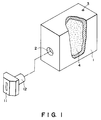
- FIG. 1 there is shown such an ink container cartridge of this type.
- An outer wall of the container cartridge 1 is provided with an ink supply port 2 for supplying the ink to a recording head 11.
- an ink supply tube 12 is connected with an ink supply port 2
- a liquid passage is established between the ink container cartridge 1 and the recording head 11.
- the ink supply port and the ink supply tube 12 ace connected with an unshown connecting tube.
- An air vent 3 is formed through an outer wall of the ink container cartridge 1 to permit introduction of the air thereinto.
- the inside of the ink container 1 is filled with an ink retaining material 4.
- the material of the ink retaining material 4 include felt, porous material having continuous pores, or the like. Particularly, it is preferable to use sponge of polyurethane foam or the like because it is easy to adjust the ink retaining power.
- the ink supply port 2, and preferably the air vent 3 also, are required to be hermetically sealed to prevent ink leakage or ink evaporation until it is connected with the ink supply tube 12 of the recording head 11 for use, that is, during the transportation or storage thereof before the use thereof.
- a sealing tape 5 is generally used.
- the sealing tape 5 is a barrier material (so-called in the field of packing).
- a material similar to the body of the container cartridge 1 is used as a bonding layer for the barrier material, so that the bonding layer is fused to increase the sealing property. This is preferable.
- Figures 2A and 2B illustrate prior art of the sealing of the ink supply port 2 using a sealing tape 5.
- Figure 2A is a perspective view illustrating a sealing tape 5 and a wall 1a of the container cartridge 1 which has the ink supply port 2.
- Figure 2B is a sectional view of the ink supply port 2 in the state that it is sealed by the sealing tape 5.
- the shock upon the removal of the sealing tape 5, or pressing by the fingers to the container cartridge 1 upon the removal of the sealing tape 5, may result in the scattering of the ink.
- the removal operation of the sealing tape 5 has to be carried out with quite high care, thus deteriorating the operativity.
- the structure of the ink container cartridge described hereinbefore is used as the structure of the container cartridge, there arises a problem from the standpoint of the ink supply to the recording head (it is difficult to produce a desired negative pressure).
- the structure of the ink supply port becomes bulky with cost increase.
- a known package and a method of opening the package accommodating a container cartridge is shown in the document JP-A-62 019 460.
- This document discloses a package accommodating a container cartridge comprising a sealing member for sealing an ink supply portion of the container cartridge, wherein the sealing member in the form of a cushion rubber is at least partly mounted to the package.
- an object of the present invention to provide a package and a method of opening the package such that the quantity of the ink scattered or discharged out of the container cartridge through an opening or openings of the cartridge is small when the opening or openings are unsealed.
- the package accommodating a container cartridge provided with an ink supply portion integral with a recording head in use has
- the method of unpacking a container cartridge provided with an ink supply portion integral with a recording head in use the container cartridge is accommodated in a package, a sealing member sealing the ink supply portion is at least partly mounted to the package and is attached to the ink supply portion, comprising the steps of:
- the method of unpacking a container cartridge provided with an ink supply portion integral with a recording head in use the container cartridge is accommodated in a package, a long sealing member seals the ink supply portion the rest of the sealing member is returned into the package and is extended to the outside of the package and an other end of the sealing member adjacent the portion sealing the ink supply portion is made integral with the package, comprising the steps of:
- Figure 1 is a perspective view of an example of a head cartridge and a container cartridge.
- Figures 2A and 2B illustrate a configuration of an ink supply port in a conventional ink container and a sealing for the ink supply port using a sealing tape.
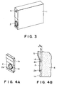
- Figure 3 shows an example of a container cartridge.
- Figure 4 illustrates a configuration of an ink supply port in a container cartridge and sealing for an ink supply port by a sealing material.
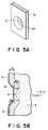
- Figure 5 shows an example of a configuration of an ink supply port in a container cartridge and sealing for an ink supply port by a sealing material.
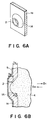
- Figure 6 shows a configuration of an ink supply port in a container cartridge and sealing for an ink supply port by a sealing material, in a further example.
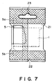
- Figure 7 illustrates an example of a packing case containing a container cartridge.
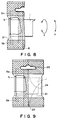
- Figure 8 illustrates an example in which a packing case is opened.
- Figure 9 illustrates another example of a packing case containing a container cartridge.
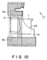
- Figure 10 illustrates another example in which the packing case is opened.
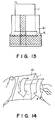
- Figure 11 illustrates a further example of a packing case containing a container cartridge.
- Figure 12 is a perspective view illustrating a method of opening the packing case of Figure 11.
- Figure 13 illustrates the packing case of Figure 11 when it is opened.
- Figure 14 illustrates the packing case of Figure 11, from which the ink cartridge is being taken out.
- Figure 15 illustrates a further example of a packing case containing a container cartridge.
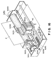
- Figure 16 is a perspective view of an example of an ink jet recording apparatus.
- FIG. 3 is a perspective view of an exchangeable container cartridge 1 to which the present invention is applied.
- the container cartridge 1 is provided at least with an ink supply port 2 for connection with an unshown ink supply tube of an ink jet recording head, and an air vent 3 for permitting introduction of the air required for the ink to be supplied out from the container cartridge 1.
- the present invention is applicable to a container cartridge 1 if it is provided with at least two openings such as an ink supply port 2 and an air vent 3, irrespective of the structure in the container cartridge 1. Accordingly, it may be a container cartridge integral with an ink jet recording head and containing porous ink retaining material in the entirety of the ink container, a container cartridge containing only ink therein, and a container cartridge in the form of a combination of the above two, which, for example, comprises an opening for connection with an ink jet recording head, a negative pressure generating material accommodating portion for accommodating a negative pressure generating material (ink absorbing material), an ink accommodating portion adjacent to the negative pressure generating material and connected therewith at a bottom.
- the present invention is suitably applicable to an ink cartridge having a negative pressure generating material accommodating portion and an ink accommodating portion.
- Figures 4A and 4B illustrate an ink container cartridge according to a first embodiment of the present invention.
- Figure 4A is a perspective view of such a wall of the container cartridge as is provided with an ink supply port 2.
- Figure 4B is a sectional view of the ink supply port 2 which is hermetically sealed by a sealing tape (material) 5.
- Designated by a reference 1a is a part of the wall provided with the ink supply port 2 in the container cartridge.
- the portion around the ink supply port 2 is provided with a thin wall portion 1a, so that the thickness of the container cartridge wall t 1 is smaller than that t 0 of a conventional wall of Figure 3. Therefore, the gap between the sealing tape 5 and the ink retaining member 4 at the ink supply port 2 is t 1 , and therefore, a volume of the space formed there is t 1 /t 0 , as compared with the conventional volume, thus reducing the volume of the space in which the ink from the ink retaining material 4 can stagnate. Therefore, the quantity of the ink stagnating there can be reduced to such an extent that the quantity of the ink scattered upon the removal of the sealing tape 5 does not result in contamination. Additionally, the waste of the ink can be avoided. In other words, the sealing tape 5 can be easily removed, thus improving the operativity.
- the container cartridge is manufactured by molding a plastic material.
- a proper wall thickness (basic wall thickness) for permitting proper molding. It is different if the material is different. For this reason, it is not preferable to reduce the thickness t 1 too much. However, by reducing it as much as possible, the above described object can be accomplished.
- FIG. 4 Another configuration other than that shown in Figure 4 is usable to reduce the wall thickness of the ink container.
- the cross-section of the ink supply port 2 may be other than circular which is shown in Figure 4.
- Figure 5 illustrates a container cartridge according to another embodiment.
- Figure 5A is a perspective view of a wall portion of the container cartridge provided with the ink supply port 2.
- Figure 5B is a sectional view of an ink supply port 2 which is sealed by a sealing tape 5.
- Designated by a reference 1a is a part of a wall provided with the ink supply port 2.
- the peripheral portion of the ink supply port 2 is recessed into the container cartridge 1 (1A), so that the wall 1a is recessed into the inside by a thickness t 4 .
- the ink retaining material 2 is compressed in a direction of an arrow C1 by the recess 1a of the container cartridge wall.
- the ink retaining material bulges by its elasticity toward the space in the ink supply port 2 in the direction of an arrow C2.
- the space formed between the sealing tape 5 and the ink retaining member 4 in the ink supply port 2 is partly occupied by the ink retaining material 4, so that the volume of the space is reduced as compared with the conventional example shown in Figure 2. Accordingly, the volume of the space in which the ink from the ink retaining material 2 can stagnate, can be reduced.
- the degree t 4 of the recess of the container wall is properly determined by one skilled in the art in accordance with the size of the ink supply port 2 and the elasticity of the ink retaining material 4, with the view to reducing the volume as much as possible.
- the configuration of the recess is not limited to that shown in Figure 5.
- the cross-section of the ink supply port 2 may be other than circular, which is shown in Figure 5.
- Figure 6 illustrates an ink container according to a further embodiment of the present invention.
- Figure 6A is a perspective view of a wall portion of the ink container provided with the ink supply port 13.
- Figure 6B is a sectional view of the ink supply port 13 which is sealed by a sealing member 16.
- Designated by a reference numeral 51 is a part of the wall provided with the ink supply port 13.
- the degree of projection is indicated by t 5 .
- the size of the ink retaining material 4 measured in a direction of an arrow D2 is such that it extends beyond an inside surface of the container by not less than t 5 .
- the ink retaining material is compressed in a direction D1, and therefore, the elasticity thereof provides such a configuration that it is bulged in a direction D2 toward the space in the ink supply port 2.
- the ink retaining material 4 partly occupies the space formed between the sealing tape 5 and the ink retaining material 4 in the ink supply port 2, so that the volume in the space is reduced as compared with the conventional example of Figure 2.
- the space permitting ink stagnation can be reduced.
- the degree of projection t 5 of the ink container wall is properly determined by one skilled in the art in accordance with degree of compression in the direction D1 and the elasticity of the ink retaining material 4 and a size of the ink supply port 2, with the view to reducing the volume of the space as much as possible.
- the configuration of the projection 1a may be other than shown in Figure 6.
- the configuration of the ink supply port 2 may be non-circular, although circular example is shown in Figure 6.
- Figure 7 illustrates a container cartridge packing case according to an embodiment of the present invention.
- the openings 2 and 3 of the container cartridge 1 are sealed by a sealing tape 5.
- a fusing layer of the sealing tape 5 and a fusing layer of the packing material 21 are fused together by heat at portions indicated by 5a and 5b.
- the hatched portions in this Figure are portions of the packing case which are bonded together or another material.
- the packing case or material 21 is provided with a notch and a hole engageable with a hook 23 in a shop.
- the sealing tape and at least two openings of the container cartridge 1 may be bonded by pressure, adhesive material, fusing and/or combination thereof, provided that the sealing is enough to prevent evaporation of the ink in the container cartridge and to endure against expansion of the air or ink therein. From the standpoint of high reliability, fusing type is preferable.
- the sealing tape 5 a single layer barrier (so-called in the field of package) or a multi-layer barrier is preferably used. It is further preferable that the fusing layer of the sealing tape may be of the same or similar material as the main body of the container cartridge and/or the connecting portion of the package material. Another sealing tape material such as paper is usable, provided that the sealing is possible by pressure, bonding or fusing.
- the package material shown in Figure 7 is opened by tearing from the notch 6, as shown in Figure 8 (first opening step).
- first opening step By this, non-sealed portion of the container cartridge (without the sealing tape 4) is exposed.
- second opening step the partly exposed cartridge is separated from the package material 21.
- the container cartridge 1 is rotated in a direction indicated by arrows a and b.
- the container cartridge may be pulled off the package material by one hand with the upper part of the package material 21 adjacent the sealing tape 5 being nipped by the fingers of the other hand. By doing so, the ink supply port 2 and the air vent 3 of the container cartridge is unsealed, to permit the container cartridge 1 to be taken out of the package.
- the non-seal portion of the container cartridge is exposed by the first step of the opening action.
- the container cartridge is, in effect, connected with the packing material 21 by the sealing tape 5, and therefore, the container cartridge does not pop out of the package material 21 by the first opening step. For this reason, contamination can be prevented even if the container cartridge is let fall thereafter. It is not until after the second opening step that the container cartridge is taken out.
- the sealing tape 5 is removed from the opening of the container cartridge, the openings 2 and 3 of the container cartridge are still within the package material.
- the ink scatters only into the package material so that the result is only the contamination of the inside of the package material, without contamination of the operator's hand or clothes.
- the package is perforated at 24.
- the first opening step is facilitated, and it is assured that the first step of the opening results in exposing only a corner portion of the container cartridge.
- the exposed corner portion of the container cartridge is nipped, and a lower portion of the package is nipped by fingers of the other hand, and thereafter, the cartridge is rotated in a direction indicated by an arrow c.
- the opening provided by the perforation 24 assures the rotational direction (c) when the cartridge is taken out of the package. In this manner, the liability of popping out of the cartridge in the first step can be assuredly prevented.
- the sealing tape is first removed from the air vent 3, and thereafter, it is removed from the ink supply port 2. Since the size of the air vent 3 is generally smaller, the scattering of the ink from the ink supply port 2 can be further reduced because the first release of the air vent 3 provides the atmospheric pressure with the inside of the ink container, and therefore, the atmospheric pressure is established in the ink container when the ink supply port 2 is released from the sealing tape. This advantageous effect is assured by the manner of the perforation formed in the package, in this embodiment. Referring to Figure 11, there is shown a package according to another embodiment of the present invention.
- one side 5a of the sealing tape 5 is fused along one side of the packing material 21.
- a tear tape 25 is bonded or fused on one complete circumferential inside surface of the packing material 21.
- the position of the tear tape 25 is such that when the package is opened about one half of the cartridge 1 is exposed so as to permit easy handling by the operator.
- An end of the tear tape 25 projects out for the easy operation.
- Designated by 26 is a printed portion for an identification mark such as bar code or the like on the package material.
- Figure 12 illustrates the opening operation.
- the package is opened.
- a part of the cartridge 1 is exposed.
- the first stage of the opening becomes easy without imparting undesirable vibration or the like to the container cartridge.
- the second opening step a portion of the package material 21 where the sealing tape 5 is fused, is nipped by the fingers of one hand, and the exposed portion of the cartridge is nipped by the fingers of the other hand, and the cartridge is rotated in a direction e, as shown in Figure 14.
- the sealing tape 5 is removed from the ink supply port 2 and the air vent 3 of the container cartridge 1, so that the container cartridge can be taken out of the package 21.
- the package is hermetically sealed.
- the hermetical sealing is not desirable, but it is desirable that the inside of the package is partly opened to the atmosphere.
- the distribution of the ink in the container cartridge is such that it is dense adjacent the ink supply port 2 to assure the ink supply to the recording head so that as small as possible amount of the ink is present adjacent the air vent 3. Therefore, it is preferable that when the sealing tape is removed from the container cartridge, it is preferable that it is removed first from the air vent 3.
- the opening of the air vent 3 having a smaller opening area than the ink supply port 2 provides the atmospheric pressure with the inside of the ink cartridge, thus properly preventing the ink discharge through the ink supply port 2.
- FIG 15 there is shown a further embodiment in which the order of removal (first the air vent 3, and then the ink supply port 2) of the sealing tape can be further preferably carried out.
- a long sealing tape 5 is used the rest of the sealing tape 5 adjacent the portion sealing the air vent 3 is returned into the package and is extended to the outside of the package, and an end 5b of the sealing tape adjacent the portion sealing the ink supply port 2 is made integral with the package material 21.
- the sealing tape 5 is removed assuredly in the order of the air vent 3 and the ink supply port 2.
- the sealing tape 5 may be further extended along the inside of the package 21 as a tear tape, as shown in Figure 11, in which case the sealing tape 25 is continuous with the tear tape.
- the removal occurs at acute angle, since then the removal can be accomplished with smaller force.
- the direction of removal is close to 180 degrees.
- the ink coming out of the container when the sealing tape is removed is discharged into the package case, and therefore, the discharged ink is of no problem.
- a combination of an embodiment of the ink container described hereinbefore and an embodiment of the package is desirable since then only a small quantity of the ink is discharged into a package upon the unsealing, from the standpoint of additional reliability and saving sate of ink.
- FIG 16 there is shown in a perspective view an example of an ink jet recording apparatus IJRA usable with the container cartridge described in the foregoing.
- a carriage HC is provided with a pin (not shown) engageable with a helical groove 5005 of the lead screw 5004 so that the carriage HC is reciprocated in a longitudinal direction of the apparatus.
- Designated by a reference numeral 5002 is a cap for capping a front side of each of recording heads in a recording head unit to be mounted on the carriage HC. It is used for recovery of the recording head, using unshown sucking means for sucking the ink out of the capped space.
- Each of the recording heads is provided with ejection outlets directed downwardly.
- Each recording head is connected with a container cartridge T.
- the cap 5002 is moved by a driving force transmitted thereto through a gear 5041 or the like so as to cap the ejection side surface of the recording head. Adjacent the cap 5002, there is provided an unshown cleaning blade for cleaning the ejection side surface of the recording head.
- the blade is supported for vertical movement in the Figure. As for the blade, any known cleaning blade is usable.
- the capping, cleaning and sucking operations are carried out when the carriage HC has reached the home position by the lead screw 5005. However, they may be carried out at known proper timing.
- Connection pads 4502 of the recording head unit mounted on the carriage HC are electrically connected with connection pads 5031 by rotation of a coupling plate 5030 of the carriage HC.
- a volume of a space between a sealing material and an ink retaining material adjacent an ink supply port of the ink container is reduced by the structure of the wall adjacent the ink supply port, so that the quantity of the ink stagnating in the space is significantly reduced. Therefore, the quantity of the ink scattered from the ink supply port upon removal of the sealing member, can be suppressed, and therefore, the operativity is improved.
- the ink leakage or another inconvenience can be avoided during translation thereof alone, so that high reliability is assured with simple structure and low cost.
- any user can easily open the package without scattering of the ink and contamination of the clothes or hand thereby.
- a package material for accommodating a container cartridge provided with an ink supply portion integral with a recording head in use includes a package material for accommodating the container cartridge, provided with opening means for permitting opening of the package material; a sealing material for sealing an ink supply portion of the container cartridge; wherein the sealing member is at least partly mounted to the package material.
Landscapes
- Engineering & Computer Science (AREA)
- Mechanical Engineering (AREA)
- Ink Jet (AREA)
- Control And Other Processes For Unpacking Of Materials (AREA)
- Supplying Of Containers To The Packaging Station (AREA)
- Closures For Containers (AREA)
Claims (17)
- Emballage (21) logeant une cartouche réservoir (1) comportant une partie (2) d'alimentation en encre qui, à l'utilisation, est monobloc avec une tête d'enregistrement, ledit emballage (21) étant munid'un moyen d'ouverture (22, 25) permettant l'ouverture dudit emballage (21) etd'un élément d'obturation (5) obturant ladite partie (2) d'alimentation en encre de la cartouche réservoir (1), ledit élément d'obturation (5) étant monté au moins partiellement sur ledit emballage (21),
caractérisé en ce queledit élément d'obturation (5) est monté au moins partiellement sur ledit emballage (21) à une position distante dudit moyen d'ouverture (22, 25) et il est fixé à ladite partie d'alimentation en encre (2) de façon qu'une traction exercée sur ladite cartouche réservoir (1) pour l'extraire dudit emballage (21) provoque l'enlèvement dudit élément d'obturation (5) de ladite partie d'alimentation en encre (2) alors que ladite partie d'alimentation en encre (2) est encore à l'intérieur dudit emballage (21). - Emballage (21) logeant une cartouche réservoir (1) comportant une partie d'alimentation en encre (2) qui, à l'utilisation, est monobloc avec une tête d'enregistrement, ledit emballage (21) comportantun moyen d'ouverture (22, 25) permettant l'ouverture dudit emballage (21) etun élément d'obturation (5) obturant ladite partie d'alimentation en encre (2) de la cartouche réservoir (1), ledit élément d'obturation (5) étant monté au moins en partie sur ledit emballage (21),
caractérisé en ce queledit élément d'obturation (5) est allongé de façon qu'une extrémité (5b) de l'élément d'obturation (5) qui est voisine de la partie obturant la partie d'alimentation en encre (2) soit rendue monobloc avec l'emballage (21) et que l'autre extrémité de l'élément d'obturation (5) soit retournée dans l'emballage (21) et parvienne à l'extérieur de l'emballage (21) de façon que ledit élément d'obturation (5) puisse être enlevé par traction exercée sur l'extrémité de l'élément d'obturation (5a) qui parvient à l'extérieur de l'emballage (21) avant que l'emballage (21) soit ouvert. - Emballage selon la revendication 1, dans lequel ledit moyen d'ouverture (22, 25) est une encoche réalisée dans une partie dudit emballage (21) de manière à ne permettre qu'à une partie de la cartouche réservoir (1) qui est distante de la partie d'alimentation en encre (2) d'être mise à découvert lorsque l'emballage (21) est ouvert.
- Emballage selon la revendication 1, dans lequel ledit moyen d'ouverture (22, 25) est une perforation réalisée dans ledit emballage (21) de manière à ne permettre qu'à une partie de la cartouche réservoir (1) qui est distante de la partie d'alimentation en encre (2) d'être mise à découvert lorsque l'emballage (21) est ouvert.
- Emballage selon la revendication 1, dans lequel ledit moyen d'ouverture (22, 25) est un ruban placé dans ledit emballage (21) de manière à ne permettre qu'à une partie de la cartouche réservoir (1) qui est distante de la partie d'alimentation en encre (2) d'être mise à découvert lorsque l'emballage (21) est ouvert.
- Emballage selon l'une des revendications 1, 3 ou 4, dans lequel ledit élément d'obturation (5) est en forme de ruban et l'une de ses extrémités longitudinales ou toutes les deux (5a, 5b) est ou sont liée(s) à l'emballage (21) par fusion.
- Emballage selon la revendication 1 ou 5, dans lequel ledit élément d'obturation (5) est en forme de ruban et une face latérale est liée par fusion à l'emballage (21) et l'autre partie d'extrémité latérale obture la partie d'alimentation en encre.
- Emballage selon la revendication 1 , dans lequel ladite cartouche réservoir (1) comporte une purge d'air (3) et dans lequel ledit élément d'obturation (5) obture aussi la purge d'air (3).
- Emballage selon la revendication 1 , dans lequel une épaisseur de paroi (t1) de la partie d'alimentation en encre (2) de la cartouche réservoir (1) est inférieure à une épaisseur (t0) d'une partie de paroi qui l'entoure.
- Emballage selon la revendication 1 , dans lequel ladite cartouche réservoir (1) contient une matière d'absorption d'encre (4) qui est déformée par son élasticité en pénétrant dans la partie d'alimentation en encre (2).
- Emballage selon la revendication 1 , dans lequel la partie d'alimentation en encre (2) est entourée d'une nervure (2a) saillante vers l'extérieur.
- Emballage selon la revendication 8 , dans lequel la purge d'air (3) est entourée d'une nervure saillante vers l'extérieur.
- Procédé de déballage d'une cartouche réservoir (1) comportant une partie d'alimentation en encre (2) qui, à l'utilisation, est monobloc avec une tête d'enregistrement, ladite cartouche réservoir (1) est logée dans un emballage, un élément d'obturation (5) qui obture ladite partie d'alimentation en encre (2) est monté au moins en partie sur ledit emballage (21) et est fixé à ladite partie d'alimentation en encre (2), comprenant les étapes de :mise à découvert d'une partie seulement de la cartouche réservoir (1) par ouverture de l'emballage (21),exercice d'une traction sur la cartouche réservoir (1) pour l'extraire dudit emballage (21) etenlèvement dudit élément d'obturation (5), l'étape d'exercice d'une traction sur ladite cartouche réservoir (1) pour l'extraire dudit emballage (21) provoquant l'enlèvement dudit élément d'obturation (5) de ladite partie d'alimentation en encre (2) pendant que ladite partie d'alimentation en encre (2) est encore à l'intérieur dudit emballage (21).
- Procédé de déballage d'une cartouche réservoir (1) comportant une partie d'alimentation en encre (2) qui, à l'utilisation, est monobloc avec une tête d'enregistrement, ladite cartouche réservoir (1) est logée dans un emballage, un élément long d'obturation (5) obture ladite partie d'alimentation en encre (2), le reste de l'élément d'obturation (5) est retourné à l'intérieur de l'emballage (21) et parvient à l'extérieur de l'emballage (21) et l'autre extrémité (5b) de l'élément d'obturation (5) qui est voisine de la partie obturant la partie d'alimentation en encre (2) est rendue monobloc avec l'emballage (21), comprenant les étapes de :mise à découvert d'une partie seulement de la cartouche réservoir (1) par ouverture de l'emballage (21),exercice d'une traction sur la cartouche réservoir (1) pour l'extraire dudit emballage (21) etenlèvement dudit élément d'obturation (5),l'étape d'enlèvement dudit élément d'obturation (5) a lieu avant que l'emballage (21) soit ouvert par traction exercée sur l'extrémité de l'élément d'obturation (5a) qui parvient à l'extérieur de l'emballage (21).
- Procédé selon la revendication 13, suivant lequel un mouvement de rotation est conféré entre ledit emballage (21) et ladite cartouche réservoir (1) à ladite étape d'enlèvement.
- Procédé selon la revendication 13, suivant lequel la cartouche réservoir (21) comporte une purge d'air (3) et ladite étape d'enlèvement est effectuée pour la partie d'alimentation en encre (2) et pour ladite purge d'air (3).
- Procédé selon la revendication 13, suivant lequel ladite cartouche réservoir (21) comporte une purge d'air (3) et suivant lequel ladite étape d'enlèvement est effectuée pour la purge d'air (3) et la partie d'alimentation en encre (2) dans cet ordre.
Applications Claiming Priority (6)
| Application Number | Priority Date | Filing Date | Title |
|---|---|---|---|
| JP122946/93 | 1993-05-25 | ||
| JP12262193A JP3165281B2 (ja) | 1993-05-25 | 1993-05-25 | 交換型インクジェット記録用インクカートリッジのパッケージおよびその開封方法 |
| JP12294693A JP3334942B2 (ja) | 1993-05-25 | 1993-05-25 | インクタンク,インクジェットカートリッジおよびインクジェット記録装置 |
| JP122621/93 | 1993-05-25 | ||
| JP22348993A JP3372600B2 (ja) | 1993-09-08 | 1993-09-08 | 梱包部材及び梱包部材の開封方法 |
| JP223489/93 | 1993-09-08 |
Publications (2)
| Publication Number | Publication Date |
|---|---|
| EP0627317A1 EP0627317A1 (fr) | 1994-12-07 |
| EP0627317B1 true EP0627317B1 (fr) | 1998-08-12 |
Family
ID=27314487
Family Applications (1)
| Application Number | Title | Priority Date | Filing Date |
|---|---|---|---|
| EP94107957A Expired - Lifetime EP0627317B1 (fr) | 1993-05-25 | 1994-05-24 | Boíte d'emballage et son procédé d'ouverture |
Country Status (10)
| Country | Link |
|---|---|
| US (1) | US5701995A (fr) |
| EP (1) | EP0627317B1 (fr) |
| KR (1) | KR0137620B1 (fr) |
| CN (1) | CN1081546C (fr) |
| AT (1) | ATE169566T1 (fr) |
| AU (1) | AU671539B2 (fr) |
| CA (1) | CA2124155C (fr) |
| DE (1) | DE69412356T2 (fr) |
| ES (1) | ES2119021T3 (fr) |
| TW (1) | TW257739B (fr) |
Cited By (2)
| Publication number | Priority date | Publication date | Assignee | Title |
|---|---|---|---|---|
| US6312115B1 (en) | 1997-03-12 | 2001-11-06 | Seiko Epson Corporation | Ink cartridge for ink jet recorder and method of manufacturing same |
| CN101437685B (zh) * | 2004-10-06 | 2011-09-14 | 惠普开发有限公司 | 储器和墨水笔组件 |
Families Citing this family (44)
| Publication number | Priority date | Publication date | Assignee | Title |
|---|---|---|---|---|
| US5682186A (en) * | 1994-03-10 | 1997-10-28 | Hewlett-Packard Company | Protective capping apparatus for an ink-jet pen |
| DE69511461T2 (de) * | 1994-05-31 | 2000-04-13 | Canon Kk | Austauschbare Tintenpatrone mit Verschlussstruktur |
| JPH08230205A (ja) * | 1995-02-28 | 1996-09-10 | Canon Inc | インクタンク保護方法及び部材とこれを有するインクタンク |
| GB2310168B (en) * | 1995-04-21 | 1998-01-07 | Seiko Epson Corp | An ink replenishment pack for ink supplied recording apparatus |
| AU705309B2 (en) * | 1995-04-21 | 1999-05-20 | Seiko Epson Corporation | An ink replenishment pack for ink supplied recording apparatus |
| US5953030A (en) * | 1995-04-24 | 1999-09-14 | Canon Kabushiki Kaisha | Ink container with improved air venting structure |
| US6168266B1 (en) | 1995-09-29 | 2001-01-02 | Canon Kabushiki Kaisha | Ink tank cartridge, a manufacturing method thereof and a packaging structure of the ink tank cartridge |
| JP3177137B2 (ja) | 1995-09-29 | 2001-06-18 | キヤノン株式会社 | インクジェット用インクカートリッジおよび該インクジェット用インクカートリッジの開口部封止方法 |
| JP3327807B2 (ja) * | 1996-03-01 | 2002-09-24 | キヤノン株式会社 | インクタンクの包装構造および該包装構造が施されるインクタンク |
| JPH10193636A (ja) * | 1996-11-18 | 1998-07-28 | Mitsubishi Pencil Co Ltd | 補充用インクカートリッジ |
| JPH10250111A (ja) * | 1997-03-17 | 1998-09-22 | Brother Ind Ltd | インクカートリッジの包装体 |
| JP3952547B2 (ja) * | 1997-08-11 | 2007-08-01 | ブラザー工業株式会社 | インクカートリッジ梱包体及びその製造方法 |
| AUPO956597A0 (en) * | 1997-10-01 | 1997-10-30 | Calidad Distributors Pty Ltd | Method and apparatus for protecting electronic contacts on printer ink cartridge during insertion to and removal from printer |
| US6270207B1 (en) * | 1998-03-30 | 2001-08-07 | Brother Kogyo Kabushiki Kaisha | Ink cartridge and remaining ink volume detection method |
| EP0958927B1 (fr) * | 1998-04-23 | 2003-10-29 | Esselte N.V. | Dispositif d'impression de ruban et cassette à ruban |
| JP3669179B2 (ja) | 1998-10-15 | 2005-07-06 | セイコーエプソン株式会社 | インクカートリッジ装置 |
| JP3592112B2 (ja) * | 1998-12-24 | 2004-11-24 | キヤノン株式会社 | 液体供給システム、液体収納容器、およびヘッドカートリッジ |
| JP2001071522A (ja) | 1999-09-03 | 2001-03-21 | Canon Inc | 液体容器およびプリント装置 |
| JP2001199082A (ja) | 1999-10-08 | 2001-07-24 | Seiko Epson Corp | インクカートリッジ、インクジェット記録装置、及びインクカートリッジの装着方法 |
| JP2001260376A (ja) * | 2000-03-16 | 2001-09-25 | Nec Corp | インクカートリッジ及びインクジェット式プリンタ |
| US6959976B2 (en) * | 2001-03-28 | 2005-11-01 | Hewlett-Packard Development Company, L.P. | Hot-melt seal for nozzles on print cartridges and method |
| JP3774675B2 (ja) * | 2001-05-10 | 2006-05-17 | キヤノン株式会社 | パッケージ |
| US6764170B2 (en) * | 2001-06-14 | 2004-07-20 | Hewlett-Packard Development Company, L.P. | Removable label for sealing an ink-jet ink reservoir |
| US6786583B2 (en) | 2001-08-30 | 2004-09-07 | Seiko Epson Corporation | Ink cartridge storage structure and method |
| CN100406262C (zh) * | 2002-03-18 | 2008-07-30 | 佳能株式会社 | 液体容器 |
| JP4250433B2 (ja) | 2002-03-18 | 2009-04-08 | キヤノン株式会社 | 液体収納容器の包装構造およびその開封方法 |
| JP3919567B2 (ja) * | 2002-03-18 | 2007-05-30 | キヤノン株式会社 | 液体収納容器の包装構造およびその開封方法 |
| JP4161846B2 (ja) * | 2003-08-08 | 2008-10-08 | セイコーエプソン株式会社 | 液体収容体 |
| US7384133B2 (en) | 2003-08-08 | 2008-06-10 | Seiko Epson Corporation | Liquid container capable of maintaining airtightness |
| US7219979B2 (en) * | 2004-02-10 | 2007-05-22 | Lexmark International, Inc. | Inkjet printhead packaging tape for sealing nozzles |
| US7102519B2 (en) * | 2004-04-30 | 2006-09-05 | Hewlett-Packard Development Company, L.P. | Concentric tag-reader method and system for RFID |
| US7611222B2 (en) * | 2004-10-06 | 2009-11-03 | Hewlett-Packard Development Company, L.P. | Nozzle shield assembly |
| US8313185B2 (en) | 2006-03-31 | 2012-11-20 | Canon Kabushiki Kaisha | Liquid container and liquid container package |
| JP4823038B2 (ja) * | 2006-12-06 | 2011-11-24 | キヤノン株式会社 | インクジェットヘッドカートリッジ、記録ヘッド、インク収納容器及びインクジェットヘッドカートリッジの製造方法 |
| JP4332752B2 (ja) * | 2006-12-28 | 2009-09-16 | ブラザー工業株式会社 | インクカートリッジ |
| US7530680B2 (en) * | 2007-01-30 | 2009-05-12 | Brother Kogyo Kabushiki Kaisha | Ink cartridges having signal blocking portions |
| US8322835B2 (en) | 2007-02-19 | 2012-12-04 | Seiko Epson Corporation | Sealing structure of fluid container, and method of manufacturing and reusing fluid container |
| US8025378B2 (en) * | 2007-03-28 | 2011-09-27 | Brother Kogyo Kabushiki Kaisha | Ink cartridges |
| JP2010036457A (ja) * | 2008-08-05 | 2010-02-18 | Seiko Epson Corp | 液体容器、包装された液体容器及びその製造方法 |
| JP6375747B2 (ja) * | 2014-07-17 | 2018-08-22 | セイコーエプソン株式会社 | 液体収容容器 |
| US10035355B2 (en) | 2016-10-13 | 2018-07-31 | Funai Electric Co., Ltd. | Packaging system for fluidic ejection cartridge with cartridge orientation control |
| US9878554B1 (en) | 2016-10-13 | 2018-01-30 | Funai Electric Co., Ltd. | Packaging system for fluidic ejection cartridge with controlled protective tape removal |
| JP7246978B2 (ja) | 2019-03-15 | 2023-03-28 | キヤノン株式会社 | 液体吐出装置及び液体充填方法 |
| JP7391637B2 (ja) | 2019-12-03 | 2023-12-05 | キヤノン株式会社 | 液体貯蔵装置および液体充填方法 |
Family Cites Families (17)
| Publication number | Priority date | Publication date | Assignee | Title |
|---|---|---|---|---|
| GB812278A (en) * | 1955-06-27 | 1959-04-22 | Gustav Schickedanz | Method of packing and packaging for pocket handkerchiefs |
| US3001674A (en) * | 1957-10-04 | 1961-09-26 | Barbara C Wooten | Container and cover therefor with removable band |
| US3002674A (en) * | 1957-12-10 | 1961-10-03 | Wright Charles Edmund | Improvements in paper bags and the like |
| US2920759A (en) * | 1958-05-05 | 1960-01-12 | Kimberly Clark Co | Cellulosic product |
| US3002694A (en) * | 1959-04-27 | 1961-10-03 | Grant Norman Cecil Scott | Spray bars for tar and the like spraying machines |
| US4170305A (en) * | 1978-08-11 | 1979-10-09 | Johnson & Johnson | Easy-open wrapper for cylindrical products |
| US4275835A (en) * | 1979-05-07 | 1981-06-30 | Miksic Boris A | Corrosion inhibiting articles |
| US4582685A (en) * | 1982-10-07 | 1986-04-15 | Helena Laboratories Corporation | Test kit for performing a medical test |
| US4598826A (en) * | 1984-11-09 | 1986-07-08 | Minnesota Mining And Manufacturing Company | Heat-sealable, laminated package |
| JPS6219460A (ja) * | 1985-07-19 | 1987-01-28 | Ricoh Co Ltd | インクカ−トリツジの梱包容器 |
| US4648509A (en) * | 1986-07-14 | 1987-03-10 | Alves Dario M | Tamper-proof package and method |
| US5231416A (en) * | 1988-11-09 | 1993-07-27 | Canon Kabushiki Kaisha | Container for ink jet head and recovering method of ink jet head using container |
| AU645492B2 (en) * | 1989-05-01 | 1994-01-20 | Canon Kabushiki Kaisha | Container for ink jet head cartridge |
| AU635562B2 (en) * | 1989-09-18 | 1993-03-25 | Canon Kabushiki Kaisha | Recording head with cover |
| US5244092A (en) * | 1989-12-06 | 1993-09-14 | Canon Kabushiki Kaisha | Package for ink jet cartridge |
| WO1991008267A1 (fr) * | 1989-12-06 | 1991-06-13 | Canon Kabushiki Kaisha | Ruban autoadhesif, tete d'enregistrement a jet d'encre, et procede de stockage |
| JPH0516387A (ja) * | 1991-07-15 | 1993-01-26 | Canon Inc | インクジエツトカートリツジ用パツケージ |
-
1994
- 1994-05-24 AT AT94107957T patent/ATE169566T1/de not_active IP Right Cessation
- 1994-05-24 AU AU63300/94A patent/AU671539B2/en not_active Ceased
- 1994-05-24 CA CA002124155A patent/CA2124155C/fr not_active Expired - Fee Related
- 1994-05-24 KR KR1019940011272A patent/KR0137620B1/ko not_active IP Right Cessation
- 1994-05-24 EP EP94107957A patent/EP0627317B1/fr not_active Expired - Lifetime
- 1994-05-24 ES ES94107957T patent/ES2119021T3/es not_active Expired - Lifetime
- 1994-05-24 DE DE69412356T patent/DE69412356T2/de not_active Expired - Lifetime
- 1994-05-25 CN CN94105828A patent/CN1081546C/zh not_active Expired - Fee Related
- 1994-05-27 TW TW083104832A patent/TW257739B/zh not_active IP Right Cessation
-
1996
- 1996-09-19 US US08/716,090 patent/US5701995A/en not_active Expired - Lifetime
Cited By (4)
| Publication number | Priority date | Publication date | Assignee | Title |
|---|---|---|---|---|
| US6312115B1 (en) | 1997-03-12 | 2001-11-06 | Seiko Epson Corporation | Ink cartridge for ink jet recorder and method of manufacturing same |
| US6854834B2 (en) | 1997-03-12 | 2005-02-15 | Seiko Epson Corporation | Ink cartridge for ink-jet recorder and method of manufacturing same |
| US6929359B2 (en) | 1997-03-12 | 2005-08-16 | Seiko Epson Corporation | Ink cartridge for ink-jet recorder and method of manufacturing same |
| CN101437685B (zh) * | 2004-10-06 | 2011-09-14 | 惠普开发有限公司 | 储器和墨水笔组件 |
Also Published As
| Publication number | Publication date |
|---|---|
| AU6330094A (en) | 1994-12-15 |
| DE69412356D1 (de) | 1998-09-17 |
| US5701995A (en) | 1997-12-30 |
| ES2119021T3 (es) | 1998-10-01 |
| CA2124155C (fr) | 2000-01-25 |
| ATE169566T1 (de) | 1998-08-15 |
| KR0137620B1 (ko) | 1998-05-15 |
| EP0627317A1 (fr) | 1994-12-07 |
| AU671539B2 (en) | 1996-08-29 |
| CA2124155A1 (fr) | 1994-11-26 |
| DE69412356T2 (de) | 1999-04-01 |
| TW257739B (fr) | 1995-09-21 |
| CN1081546C (zh) | 2002-03-27 |
| CN1100995A (zh) | 1995-04-05 |
Similar Documents
| Publication | Publication Date | Title |
|---|---|---|
| EP0627317B1 (fr) | Boíte d'emballage et son procédé d'ouverture | |
| KR0153550B1 (ko) | 잉크 카트리지용 잉크 충전 방법 및 장치 | |
| EP0761450B1 (fr) | Emballage pour cartouche d'encre et procédé d'emballage | |
| US5488400A (en) | Method for refilling ink jet cartridges | |
| JP3082963B2 (ja) | 大気連通部を備えたインク収納容器及び記録ヘッド | |
| US7303090B2 (en) | Liquid container sealing jacket, and method for unsealing liquid container fitted with liquid container jacket | |
| EP2049339B1 (fr) | Cartouche d'encre rechargeable et son élément de protection | |
| JP2003267438A (ja) | 液体収納容器の包装構造およびその開封方法 | |
| US6241348B1 (en) | Package for ink cartridge and method for manufacturing the same | |
| US5686948A (en) | Method for refilling ink jet cartridges | |
| JP2004358802A (ja) | インク袋の再充填方法及びリサイクルインク袋並びにインクカートリッジ | |
| US7275816B2 (en) | Ink tank package and method of unsealing such ink tank package | |
| JP2002347258A (ja) | インクジェットプリンタ | |
| JP4394187B2 (ja) | インク補給具 | |
| JP3423617B2 (ja) | ヘッドカートリッジ | |
| JP7404826B2 (ja) | インク補給容器セット、インク補給容器、および、その梱包体 | |
| JP3416520B2 (ja) | 液体供給システム、インクジェットカートリッジ、ヘッドカートリッジ、および液体供給容器 | |
| JPH07137274A (ja) | 交換型インクジェット用インクカートリッジ | |
| JP2000255082A (ja) | インクジェット記録用インクカートリッジの包装方法 | |
| JPH11129491A (ja) | インクカートリッジ | |
| JP3372600B2 (ja) | 梱包部材及び梱包部材の開封方法 | |
| JPH07137277A (ja) | インク収容体の包装部材 | |
| JP3663733B2 (ja) | インクジェットプリンタのインクカートリッジ | |
| JP2001322294A (ja) | インクカートリッジのためのパッケージおよびインクカートリッジの梱包方法 | |
| KR100234500B1 (ko) | 잉크 카트리지 |
Legal Events
| Date | Code | Title | Description |
|---|---|---|---|
| PUAI | Public reference made under article 153(3) epc to a published international application that has entered the european phase |
Free format text: ORIGINAL CODE: 0009012 |
|
| 17P | Request for examination filed |
Effective date: 19940524 |
|
| AK | Designated contracting states |
Kind code of ref document: A1 Designated state(s): AT BE CH DE DK ES FR GB GR IE IT LI LU NL PT SE |
|
| 17Q | First examination report despatched |
Effective date: 19960116 |
|
| GRAG | Despatch of communication of intention to grant |
Free format text: ORIGINAL CODE: EPIDOS AGRA |
|
| GRAG | Despatch of communication of intention to grant |
Free format text: ORIGINAL CODE: EPIDOS AGRA |
|
| GRAH | Despatch of communication of intention to grant a patent |
Free format text: ORIGINAL CODE: EPIDOS IGRA |
|
| GRAH | Despatch of communication of intention to grant a patent |
Free format text: ORIGINAL CODE: EPIDOS IGRA |
|
| GRAA | (expected) grant |
Free format text: ORIGINAL CODE: 0009210 |
|
| ITF | It: translation for a ep patent filed |
Owner name: SOCIETA' ITALIANA BREVETTI S.P.A. |
|
| AK | Designated contracting states |
Kind code of ref document: B1 Designated state(s): AT BE CH DE DK ES FR GB GR IE IT LI LU NL PT SE |
|
| PG25 | Lapsed in a contracting state [announced via postgrant information from national office to epo] |
Ref country code: GR Free format text: LAPSE BECAUSE OF NON-PAYMENT OF DUE FEES Effective date: 19980812 Ref country code: BE Free format text: LAPSE BECAUSE OF FAILURE TO SUBMIT A TRANSLATION OF THE DESCRIPTION OR TO PAY THE FEE WITHIN THE PRESCRIBED TIME-LIMIT Effective date: 19980812 Ref country code: AT Free format text: LAPSE BECAUSE OF FAILURE TO SUBMIT A TRANSLATION OF THE DESCRIPTION OR TO PAY THE FEE WITHIN THE PRESCRIBED TIME-LIMIT Effective date: 19980812 |
|
| REF | Corresponds to: |
Ref document number: 169566 Country of ref document: AT Date of ref document: 19980815 Kind code of ref document: T |
|
| REG | Reference to a national code |
Ref country code: CH Ref legal event code: EP |
|
| REF | Corresponds to: |
Ref document number: 69412356 Country of ref document: DE Date of ref document: 19980917 |
|
| REG | Reference to a national code |
Ref country code: ES Ref legal event code: FG2A Ref document number: 2119021 Country of ref document: ES Kind code of ref document: T3 |
|
| REG | Reference to a national code |
Ref country code: CH Ref legal event code: NV Representative=s name: BOVARD AG PATENTANWAELTE |
|
| PG25 | Lapsed in a contracting state [announced via postgrant information from national office to epo] |
Ref country code: SE Free format text: LAPSE BECAUSE OF FAILURE TO SUBMIT A TRANSLATION OF THE DESCRIPTION OR TO PAY THE FEE WITHIN THE PRESCRIBED TIME-LIMIT Effective date: 19981112 Ref country code: PT Free format text: LAPSE BECAUSE OF FAILURE TO SUBMIT A TRANSLATION OF THE DESCRIPTION OR TO PAY THE FEE WITHIN THE PRESCRIBED TIME-LIMIT Effective date: 19981112 Ref country code: DK Free format text: LAPSE BECAUSE OF FAILURE TO SUBMIT A TRANSLATION OF THE DESCRIPTION OR TO PAY THE FEE WITHIN THE PRESCRIBED TIME-LIMIT Effective date: 19981112 |
|
| ET | Fr: translation filed | ||
| REG | Reference to a national code |
Ref country code: IE Ref legal event code: FG4D |
|
| PG25 | Lapsed in a contracting state [announced via postgrant information from national office to epo] |
Ref country code: LU Free format text: LAPSE BECAUSE OF NON-PAYMENT OF DUE FEES Effective date: 19990524 Ref country code: IE Free format text: LAPSE BECAUSE OF NON-PAYMENT OF DUE FEES Effective date: 19990524 |
|
| PLBE | No opposition filed within time limit |
Free format text: ORIGINAL CODE: 0009261 |
|
| STAA | Information on the status of an ep patent application or granted ep patent |
Free format text: STATUS: NO OPPOSITION FILED WITHIN TIME LIMIT |
|
| 26N | No opposition filed | ||
| REG | Reference to a national code |
Ref country code: GB Ref legal event code: IF02 |
|
| REG | Reference to a national code |
Ref country code: CH Ref legal event code: PFA Owner name: CANON KABUSHIKI KAISHA Free format text: CANON KABUSHIKI KAISHA#30-2, 3-CHOME, SHIMOMARUKO, OHTA-KU#TOKYO 146 (JP) -TRANSFER TO- CANON KABUSHIKI KAISHA#30-2, 3-CHOME, SHIMOMARUKO, OHTA-KU#TOKYO 146 (JP) |
|
| PGFP | Annual fee paid to national office [announced via postgrant information from national office to epo] |
Ref country code: CH Payment date: 20120504 Year of fee payment: 19 Ref country code: DE Payment date: 20120531 Year of fee payment: 19 Ref country code: NL Payment date: 20120516 Year of fee payment: 19 |
|
| PGFP | Annual fee paid to national office [announced via postgrant information from national office to epo] |
Ref country code: FR Payment date: 20120620 Year of fee payment: 19 Ref country code: GB Payment date: 20120517 Year of fee payment: 19 |
|
| PGFP | Annual fee paid to national office [announced via postgrant information from national office to epo] |
Ref country code: IT Payment date: 20120514 Year of fee payment: 19 |
|
| PGFP | Annual fee paid to national office [announced via postgrant information from national office to epo] |
Ref country code: ES Payment date: 20120503 Year of fee payment: 19 |
|
| REG | Reference to a national code |
Ref country code: NL Ref legal event code: V1 Effective date: 20131201 |
|
| REG | Reference to a national code |
Ref country code: CH Ref legal event code: PL |
|
| GBPC | Gb: european patent ceased through non-payment of renewal fee |
Effective date: 20130524 |
|
| PG25 | Lapsed in a contracting state [announced via postgrant information from national office to epo] |
Ref country code: CH Free format text: LAPSE BECAUSE OF NON-PAYMENT OF DUE FEES Effective date: 20130531 Ref country code: LI Free format text: LAPSE BECAUSE OF NON-PAYMENT OF DUE FEES Effective date: 20130531 Ref country code: DE Free format text: LAPSE BECAUSE OF NON-PAYMENT OF DUE FEES Effective date: 20131203 |
|
| REG | Reference to a national code |
Ref country code: DE Ref legal event code: R119 Ref document number: 69412356 Country of ref document: DE Effective date: 20131203 |
|
| PG25 | Lapsed in a contracting state [announced via postgrant information from national office to epo] |
Ref country code: IT Free format text: LAPSE BECAUSE OF NON-PAYMENT OF DUE FEES Effective date: 20130524 Ref country code: NL Free format text: LAPSE BECAUSE OF NON-PAYMENT OF DUE FEES Effective date: 20131201 |
|
| REG | Reference to a national code |
Ref country code: FR Ref legal event code: ST Effective date: 20140131 |
|
| PG25 | Lapsed in a contracting state [announced via postgrant information from national office to epo] |
Ref country code: GB Free format text: LAPSE BECAUSE OF NON-PAYMENT OF DUE FEES Effective date: 20130524 |
|
| PG25 | Lapsed in a contracting state [announced via postgrant information from national office to epo] |
Ref country code: FR Free format text: LAPSE BECAUSE OF NON-PAYMENT OF DUE FEES Effective date: 20130531 |
|
| REG | Reference to a national code |
Ref country code: ES Ref legal event code: FD2A Effective date: 20140606 |
|
| PG25 | Lapsed in a contracting state [announced via postgrant information from national office to epo] |
Ref country code: ES Free format text: LAPSE BECAUSE OF NON-PAYMENT OF DUE FEES Effective date: 20130525 |