EP0500149A2 - Appareil pour reproduire un disque d'enregistrement numérique - Google Patents
Appareil pour reproduire un disque d'enregistrement numérique Download PDFInfo
- Publication number
- EP0500149A2 EP0500149A2 EP92107743A EP92107743A EP0500149A2 EP 0500149 A2 EP0500149 A2 EP 0500149A2 EP 92107743 A EP92107743 A EP 92107743A EP 92107743 A EP92107743 A EP 92107743A EP 0500149 A2 EP0500149 A2 EP 0500149A2
- Authority
- EP
- European Patent Office
- Prior art keywords
- playback
- area
- video
- signal
- disc
- Prior art date
- Legal status (The legal status is an assumption and is not a legal conclusion. Google has not performed a legal analysis and makes no representation as to the accuracy of the status listed.)
- Granted
Links
Images


Classifications
-
- H—ELECTRICITY
- H04—ELECTRIC COMMUNICATION TECHNIQUE
- H04N—PICTORIAL COMMUNICATION, e.g. TELEVISION
- H04N9/00—Details of colour television systems
- H04N9/79—Processing of colour television signals in connection with recording
- H04N9/80—Transformation of the television signal for recording, e.g. modulation, frequency changing; Inverse transformation for playback
- H04N9/802—Transformation of the television signal for recording, e.g. modulation, frequency changing; Inverse transformation for playback involving processing of the sound signal
-
- G—PHYSICS
- G11—INFORMATION STORAGE
- G11B—INFORMATION STORAGE BASED ON RELATIVE MOVEMENT BETWEEN RECORD CARRIER AND TRANSDUCER
- G11B19/00—Driving, starting, stopping record carriers not specifically of filamentary or web form, or of supports therefor; Control thereof; Control of operating function ; Driving both disc and head
- G11B19/02—Control of operating function, e.g. switching from recording to reproducing
- G11B19/04—Arrangements for preventing, inhibiting, or warning against double recording on the same blank or against other recording or reproducing malfunctions
-
- G—PHYSICS
- G11—INFORMATION STORAGE
- G11B—INFORMATION STORAGE BASED ON RELATIVE MOVEMENT BETWEEN RECORD CARRIER AND TRANSDUCER
- G11B19/00—Driving, starting, stopping record carriers not specifically of filamentary or web form, or of supports therefor; Control thereof; Control of operating function ; Driving both disc and head
- G11B19/02—Control of operating function, e.g. switching from recording to reproducing
- G11B19/12—Control of operating function, e.g. switching from recording to reproducing by sensing distinguishing features of or on records, e.g. diameter end mark
-
- G—PHYSICS
- G11—INFORMATION STORAGE
- G11B—INFORMATION STORAGE BASED ON RELATIVE MOVEMENT BETWEEN RECORD CARRIER AND TRANSDUCER
- G11B19/00—Driving, starting, stopping record carriers not specifically of filamentary or web form, or of supports therefor; Control thereof; Control of operating function ; Driving both disc and head
- G11B19/20—Driving; Starting; Stopping; Control thereof
- G11B19/28—Speed controlling, regulating, or indicating
-
- G—PHYSICS
- G11—INFORMATION STORAGE
- G11B—INFORMATION STORAGE BASED ON RELATIVE MOVEMENT BETWEEN RECORD CARRIER AND TRANSDUCER
- G11B20/00—Signal processing not specific to the method of recording or reproducing; Circuits therefor
- G11B20/10—Digital recording or reproducing
- G11B20/10009—Improvement or modification of read or write signals
-
- G—PHYSICS
- G11—INFORMATION STORAGE
- G11B—INFORMATION STORAGE BASED ON RELATIVE MOVEMENT BETWEEN RECORD CARRIER AND TRANSDUCER
- G11B20/00—Signal processing not specific to the method of recording or reproducing; Circuits therefor
- G11B20/10—Digital recording or reproducing
- G11B20/10527—Audio or video recording; Data buffering arrangements
-
- G—PHYSICS
- G11—INFORMATION STORAGE
- G11B—INFORMATION STORAGE BASED ON RELATIVE MOVEMENT BETWEEN RECORD CARRIER AND TRANSDUCER
- G11B27/00—Editing; Indexing; Addressing; Timing or synchronising; Monitoring; Measuring tape travel
- G11B27/10—Indexing; Addressing; Timing or synchronising; Measuring tape travel
- G11B27/102—Programmed access in sequence to addressed parts of tracks of operating record carriers
- G11B27/105—Programmed access in sequence to addressed parts of tracks of operating record carriers of operating discs
-
- G—PHYSICS
- G11—INFORMATION STORAGE
- G11B—INFORMATION STORAGE BASED ON RELATIVE MOVEMENT BETWEEN RECORD CARRIER AND TRANSDUCER
- G11B27/00—Editing; Indexing; Addressing; Timing or synchronising; Monitoring; Measuring tape travel
- G11B27/10—Indexing; Addressing; Timing or synchronising; Measuring tape travel
- G11B27/19—Indexing; Addressing; Timing or synchronising; Measuring tape travel by using information detectable on the record carrier
- G11B27/28—Indexing; Addressing; Timing or synchronising; Measuring tape travel by using information detectable on the record carrier by using information signals recorded by the same method as the main recording
- G11B27/32—Indexing; Addressing; Timing or synchronising; Measuring tape travel by using information detectable on the record carrier by using information signals recorded by the same method as the main recording on separate auxiliary tracks of the same or an auxiliary record carrier
- G11B27/327—Table of contents
- G11B27/329—Table of contents on a disc [VTOC]
-
- G—PHYSICS
- G11—INFORMATION STORAGE
- G11B—INFORMATION STORAGE BASED ON RELATIVE MOVEMENT BETWEEN RECORD CARRIER AND TRANSDUCER
- G11B7/00—Recording or reproducing by optical means, e.g. recording using a thermal beam of optical radiation by modifying optical properties or the physical structure, reproducing using an optical beam at lower power by sensing optical properties; Record carriers therefor
- G11B7/004—Recording, reproducing or erasing methods; Read, write or erase circuits therefor
- G11B7/005—Reproducing
-
- G—PHYSICS
- G11—INFORMATION STORAGE
- G11B—INFORMATION STORAGE BASED ON RELATIVE MOVEMENT BETWEEN RECORD CARRIER AND TRANSDUCER
- G11B7/00—Recording or reproducing by optical means, e.g. recording using a thermal beam of optical radiation by modifying optical properties or the physical structure, reproducing using an optical beam at lower power by sensing optical properties; Record carriers therefor
- G11B7/08—Disposition or mounting of heads or light sources relatively to record carriers
- G11B7/085—Disposition or mounting of heads or light sources relatively to record carriers with provision for moving the light beam into, or out of, its operative position or across tracks, otherwise than during the transducing operation, e.g. for adjustment or preliminary positioning or track change or selection
- G11B7/08505—Methods for track change, selection or preliminary positioning by moving the head
-
- G—PHYSICS
- G11—INFORMATION STORAGE
- G11B—INFORMATION STORAGE BASED ON RELATIVE MOVEMENT BETWEEN RECORD CARRIER AND TRANSDUCER
- G11B7/00—Recording or reproducing by optical means, e.g. recording using a thermal beam of optical radiation by modifying optical properties or the physical structure, reproducing using an optical beam at lower power by sensing optical properties; Record carriers therefor
- G11B7/08—Disposition or mounting of heads or light sources relatively to record carriers
- G11B7/09—Disposition or mounting of heads or light sources relatively to record carriers with provision for moving the light beam or focus plane for the purpose of maintaining alignment of the light beam relative to the record carrier during transducing operation, e.g. to compensate for surface irregularities of the latter or for track following
- G11B7/0941—Methods and circuits for servo gain or phase compensation during operation
-
- H—ELECTRICITY
- H04—ELECTRIC COMMUNICATION TECHNIQUE
- H04N—PICTORIAL COMMUNICATION, e.g. TELEVISION
- H04N5/00—Details of television systems
- H04N5/76—Television signal recording
- H04N5/7605—Television signal recording on discs or drums
-
- H—ELECTRICITY
- H04—ELECTRIC COMMUNICATION TECHNIQUE
- H04N—PICTORIAL COMMUNICATION, e.g. TELEVISION
- H04N5/00—Details of television systems
- H04N5/76—Television signal recording
- H04N5/91—Television signal processing therefor
-
- H—ELECTRICITY
- H04—ELECTRIC COMMUNICATION TECHNIQUE
- H04N—PICTORIAL COMMUNICATION, e.g. TELEVISION
- H04N5/00—Details of television systems
- H04N5/76—Television signal recording
- H04N5/91—Television signal processing therefor
- H04N5/93—Regeneration of the television signal or of selected parts thereof
- H04N5/931—Regeneration of the television signal or of selected parts thereof for restoring the level of the reproduced signal
-
- H—ELECTRICITY
- H04—ELECTRIC COMMUNICATION TECHNIQUE
- H04N—PICTORIAL COMMUNICATION, e.g. TELEVISION
- H04N5/00—Details of television systems
- H04N5/76—Television signal recording
- H04N5/91—Television signal processing therefor
- H04N5/93—Regeneration of the television signal or of selected parts thereof
- H04N5/95—Time-base error compensation
-
- H—ELECTRICITY
- H04—ELECTRIC COMMUNICATION TECHNIQUE
- H04N—PICTORIAL COMMUNICATION, e.g. TELEVISION
- H04N9/00—Details of colour television systems
- H04N9/79—Processing of colour television signals in connection with recording
- H04N9/7921—Processing of colour television signals in connection with recording for more than one processing mode
- H04N9/7925—Processing of colour television signals in connection with recording for more than one processing mode for more than one standard
-
- H—ELECTRICITY
- H04—ELECTRIC COMMUNICATION TECHNIQUE
- H04N—PICTORIAL COMMUNICATION, e.g. TELEVISION
- H04N9/00—Details of colour television systems
- H04N9/79—Processing of colour television signals in connection with recording
- H04N9/80—Transformation of the television signal for recording, e.g. modulation, frequency changing; Inverse transformation for playback
- H04N9/82—Transformation of the television signal for recording, e.g. modulation, frequency changing; Inverse transformation for playback the individual colour picture signal components being recorded simultaneously only
- H04N9/8205—Transformation of the television signal for recording, e.g. modulation, frequency changing; Inverse transformation for playback the individual colour picture signal components being recorded simultaneously only involving the multiplexing of an additional signal and the colour video signal
- H04N9/8211—Transformation of the television signal for recording, e.g. modulation, frequency changing; Inverse transformation for playback the individual colour picture signal components being recorded simultaneously only involving the multiplexing of an additional signal and the colour video signal the additional signal being a sound signal
- H04N9/8222—Transformation of the television signal for recording, e.g. modulation, frequency changing; Inverse transformation for playback the individual colour picture signal components being recorded simultaneously only involving the multiplexing of an additional signal and the colour video signal the additional signal being a sound signal using frequency division multiplex
-
- G—PHYSICS
- G11—INFORMATION STORAGE
- G11B—INFORMATION STORAGE BASED ON RELATIVE MOVEMENT BETWEEN RECORD CARRIER AND TRANSDUCER
- G11B2220/00—Record carriers by type
- G11B2220/20—Disc-shaped record carriers
- G11B2220/25—Disc-shaped record carriers characterised in that the disc is based on a specific recording technology
- G11B2220/2537—Optical discs
- G11B2220/2545—CDs
-
- G—PHYSICS
- G11—INFORMATION STORAGE
- G11B—INFORMATION STORAGE BASED ON RELATIVE MOVEMENT BETWEEN RECORD CARRIER AND TRANSDUCER
- G11B7/00—Recording or reproducing by optical means, e.g. recording using a thermal beam of optical radiation by modifying optical properties or the physical structure, reproducing using an optical beam at lower power by sensing optical properties; Record carriers therefor
- G11B7/007—Arrangement of the information on the record carrier, e.g. form of tracks, actual track shape, e.g. wobbled, or cross-section, e.g. v-shaped; Sequential information structures, e.g. sectoring or header formats within a track
- G11B7/0079—Zoned data area, e.g. having different data structures or formats for the user data within data layer, Zone Constant Linear Velocity [ZCLV], Zone Constant Angular Velocity [ZCAV], carriers with RAM and ROM areas
-
- G—PHYSICS
- G11—INFORMATION STORAGE
- G11B—INFORMATION STORAGE BASED ON RELATIVE MOVEMENT BETWEEN RECORD CARRIER AND TRANSDUCER
- G11B7/00—Recording or reproducing by optical means, e.g. recording using a thermal beam of optical radiation by modifying optical properties or the physical structure, reproducing using an optical beam at lower power by sensing optical properties; Record carriers therefor
- G11B7/08—Disposition or mounting of heads or light sources relatively to record carriers
- G11B7/09—Disposition or mounting of heads or light sources relatively to record carriers with provision for moving the light beam or focus plane for the purpose of maintaining alignment of the light beam relative to the record carrier during transducing operation, e.g. to compensate for surface irregularities of the latter or for track following
- G11B7/095—Disposition or mounting of heads or light sources relatively to record carriers with provision for moving the light beam or focus plane for the purpose of maintaining alignment of the light beam relative to the record carrier during transducing operation, e.g. to compensate for surface irregularities of the latter or for track following specially adapted for discs, e.g. for compensation of eccentricity or wobble
- G11B7/0953—Disposition or mounting of heads or light sources relatively to record carriers with provision for moving the light beam or focus plane for the purpose of maintaining alignment of the light beam relative to the record carrier during transducing operation, e.g. to compensate for surface irregularities of the latter or for track following specially adapted for discs, e.g. for compensation of eccentricity or wobble to compensate for eccentricity of the disc or disc tracks
-
- H—ELECTRICITY
- H04—ELECTRIC COMMUNICATION TECHNIQUE
- H04N—PICTORIAL COMMUNICATION, e.g. TELEVISION
- H04N9/00—Details of colour television systems
- H04N9/79—Processing of colour television signals in connection with recording
- H04N9/87—Regeneration of colour television signals
- H04N9/8715—Regeneration of colour television signals involving the mixing of the reproduced video signal with a non-recorded signal, e.g. a text signal
-
- H—ELECTRICITY
- H04—ELECTRIC COMMUNICATION TECHNIQUE
- H04N—PICTORIAL COMMUNICATION, e.g. TELEVISION
- H04N9/00—Details of colour television systems
- H04N9/79—Processing of colour television signals in connection with recording
- H04N9/87—Regeneration of colour television signals
- H04N9/89—Time-base error compensation
- H04N9/893—Time-base error compensation using an analogue memory, e.g. a CCD shift register, the delay of which is controlled by a voltage controlled oscillator
-
- Y—GENERAL TAGGING OF NEW TECHNOLOGICAL DEVELOPMENTS; GENERAL TAGGING OF CROSS-SECTIONAL TECHNOLOGIES SPANNING OVER SEVERAL SECTIONS OF THE IPC; TECHNICAL SUBJECTS COVERED BY FORMER USPC CROSS-REFERENCE ART COLLECTIONS [XRACs] AND DIGESTS
- Y10—TECHNICAL SUBJECTS COVERED BY FORMER USPC
- Y10S—TECHNICAL SUBJECTS COVERED BY FORMER USPC CROSS-REFERENCE ART COLLECTIONS [XRACs] AND DIGESTS
- Y10S358/00—Facsimile and static presentation processing
- Y10S358/907—Track skippers, i.e. "groove skippers"
Definitions
- the present invention relates to a method and apparatus for playback of data recording discs, and in particular to a method and apparatus for playback of data recording discs (referred to hereinafter simply as discs) having digital signals recorded thereon.
- CDs Small-diameter audio discs having a diameter of approximately 12 cm and having digital signals recorded thereon, generally called "compact discs" or CDs, are now well known.
- a composite disc having an area in which is recorded an FM modulated video signal with a PCM signal superimposed thereon, as well as an area having only a PCM signal recorded.
- the area having only PCM data recorded e.g.
- audio data in PCM form may for example be disposed in an inner peripheral area of the disc, (this area being referred to hereinafter as the CD area), while the area containing the FM video signal with superimposed PCM signal (this area being referred to hereinafter as the video area) may be disposed peripherally outward from the CD area, separated therefrom by a predetermined radial distance.
- a video signal contains higher frequency components than those of the PCM signal of the video area, so that the spectrum of the signals recorded in the video area will be as shown in Fig. 7, in which A denotes the PCM signal frequency components, and B denotes the video FM signal frequency components.
- the speed of rotation of the disc must be made higher than during that used during recording of the CD area, and therefore of course during playback it is necessary to rotate the disc at a higher speed during video area playback than during CD area playback.
- the speed of disc rotation during CD area playback is several hundred r.p.m.
- the speed of rotation is two thousand plus several hundred r.p.m. for playback from the innermost periphery of that area, and is one thousand plus several hundred r.p.m. for playback from the outermost periphery of that area, so that the speed of rotation is extremely high during video area playback.
- the frequency of the error signal supplied to the servo system which controls the position of the data detection point of the pickup with respect to the disc would be substantially higher than during CD data read-out. Since the servo loop gain is lowered when a high-frequency error signal is applied, there would be a loss of positioning control for the data detection point during such video area playback operation, so that it would be difficult to achieve satisfactory reading of video data from the disc.
- various color television standards are used at present for the video data recorded in the video area, i.e. the NTSC and the PAL standards. If the television standard of the disc does not conform to that of the playback apparatus, then synchronization for video playback will not be possible, so that video data playback cannot be executed. However, in the case of a composite disc, video data are only recorded in one area of the disc, whereas audio data are recorded throughout the entire disc. Thus, it is undesirable that is should be completely impossible to perform playback of any data whatsoever from a composite disc, simply because the television standard of the video data is different from that of the playback apparatus.
- a data recording disc playback apparatus With a data recording disc playback apparatus according to the present invention, changeover of the gain of an amplifier used for error signal amplification in a servo system which controls the position of a data detection point of a pickup is executed in accordance with whether data is being read from an inner peripheral first area of the disc, in which specific data has been recorded by digital processing to be converted to a pulse train signal, and an outer peripheral second area of the disc, in which a signal consisting of a frequency modulated video signal with a specific digital signal superimposed thereon is recorded.
- a data recording disc playback apparatus incorporates an equalizer circuit for performing compensation of the frequency characteristic of a playback digital signal, and means for changeover of the equalization characteristic of the equalizer circuit in accordance with playback from the CD area and video area of the disc respectively.
- a data recording disc playback apparatus further incorporates an amplitude control circuit for controlling the amplitude of a playback digital signal, and means for changeover of a degree of control applied by the amplitude control circuit, in accordance with playback from the CD area and video area respectively of a composite disc.
- a data recording disc playback apparatus further incorporates focus servo means, tracking servo means, carriage servo means, and spindle servo means, and means for changeover of the equalization characteristic of at least one equalizer circuit of these servo means, in accordance with playback of the CD area and video area respectively of a composite disc.
- a data recording disc playback apparatus further comprises means for changeover of the gain of at least one servo amplifier of the aforementioned servo means, in accordance with playback of the CD area and video area respectively of a composite disc.
- a data recording disc playback apparatus further comprises first means for biasing the data detection point of a pick-up along a disc radial direction, second means for displacing the pickup along the disc radial direction, and means for changeover of at least one of the pulse width and peak amplitude of drive pulses which are applied to the first means and the second means in response to a jump command.
- a data recording disc playback apparatus is configured such that, when a composite disc having a color television standard which is different from that of the playback apparatus is set on the apparatus, spindle servo control is executed during playback of the video area of the disc in accordance with a phase difference between a playback clock signal contained in a playback digital signal and a reference clock signal, and output of the playback video signal is inhibited, with only a playback digital signal being produced as output.
- control of the speed of rotation of the disc is executed on the basis of an error signal which is derived on the basis of a phase difference between a playback clock signal contained in the playback video signal and a reference clock signal, irrespective of the disc area in which playback is being performed.
- control of the disc speed of rotation is executed during playback of the CD area on the basis of an error signal which is derived from the phase difference between a playback clock signal contained in a playback digital signal and a reference clock signal, and is executed during playback of the video area on the basis of an error signal which is derived from the phase difference between a playback clock signal contained in a playback video signal and a reference clock signal.
- a data playback method is characterized in detection of a condition in which the data detection point of a pickup has reached a video area of a composite disc, and initiation of reading out recorded data by the pickup at the position thus detected to thereby derive specific data, and is further characterized in that when that data has been derived, the data detection point is displaced by a predetermined number of tracks towards the CD area of the disc, with playback of recorded data being then performed.
- a data playback method applied to a playback apparatus capable of playback of both CD discs and composite discs is characterized in that disc identifier data which is recorded in a lead-in area is read at the time of disc playback, and in that if it is judged on the basis of the data thus read that the disc being played is a composite disc and that playback of the video area of that disc is designated, then the speed of rotation of the disc is accellerated towards a maximum rated speed of rotation, while the data detection point of the pickup is moved towards the video area of the disc.
- a disc 1 is rotated by a spindle motor 2, and data recorded on the disc 1 is read out by an optical type of pickup 3.
- the pickup 3 includes a built-in laser diode, object lens, focus actuator, tracking actuator, and photo-detector, etc.
- the output signals from the pickup 3 are supplied to a decoder 4, and to a video demodulator 6 within a video playback processing circuit 5.
- the decoder 4 produces a focus error signal, for example by utilizing astigmatic aberration, and a tracking error signal, for example by utilizing the 3-beam method, and further performs regeneration of a clock signal for data demodulation purposes.
- the phase of this regenerated clock signal is compared with that of a clock signal which is produced from a clock signal generating circuit 8, and generation of a spindle error signal and data demodulation by an EFM (Eight to Fourteen Modulation) are respectively executed in accordance with the phase difference between these clock signals.
- the output data from the decoder 4 is converted to an audio signal by a D/A converter 7 (digital to analog converter).
- the regenerated clock signal produced from the decoder 4 is supplied to the clock signal generating circuit 8.
- the clock signal generating circuit 8 is configured to selectively output either a clock signal having a predetermined frequency, or a clock signal whose frequency is identical to that of the regenerated clock signal, with this selection being performed in response to a servo changeover command.
- the focus error signal and the tracking error signal produced from decoder 4 are supplied to an optical servo circuit 9.
- the optical servo circuit 9 consists of a focus servo amplifier for driving the focus actuator within the pickup 3 in response to the focus error signal, a tracking servo amplifier for driving the tracking actuator in pickup 3 in response to the tracking error signal, and a carriage servo amplifier for driving a carriage motor to move the pickup 3 along a radial direction of disc 1 in response to the tracking error signal.
- the focus servo amplifier, tracking servo amplifier and carriage servo amplifier are respectively configured such that the gain of each amplifier can be increased in response to a servo changeover command.
- the spindle error signal produced from decoder 4 is supplied to a spindle servo 10, which is also supplied with an output signal from a rotation control circuit 11.
- the spindle servo 10 is configured such as to drive the spindle motor 2 in response to one of the error signals produced from decoder 4 and rotation control circuit 11, as determined by a servo changeover command.
- a data detection point i.e. spot
- the rotation control circuit 11 is also configured such as to perform separation of the sync signal component of the video signal which is produced from video demodulator 6, and to produce as output an error signal, in accordance with an amount of phase difference between this sync signal and an output signal from reference signal generating circuit 12.
- the video signal which is produced from video demodulator 6 is supplied to a time axis compensation cicrcuit 13, which is configured to apply time axis compensation to that video signal, by variation of a signal delay time.
- a variable delay element such as a CCD (Charge Coupled Device).
- the amount of delay produced by the variable delay element is determined in accordance with the phase difference between the sync signal contained in the video signal and the output signal from reference signal generating circuit 12.
- the video signal After being subjected in this way to time axis compensation in the time axis compensation circuit 13, the video signal is transferred through a video signal processing circuit 14, in which processing such as character insertion, video muting, blue image insertion, etc, is carried out.
- the video signal is then supplied to a video output terminal.
- a video area detector 15 serves to detect when the data detection point of pickup 3 has reached a video area, and can include for example a reflective or transmissive type of photo-coupler whereby light emitted form a photo-emissive element is reflected or transmitted to fall upon a photo-receptive element when the pickup 3 reaches a predetermined position.
- a video area detection signal is thereby produced from the video area detector 15 and is supplied to the system controller 16.
- the system controller 16 is also supplied with a signal which varies in accordance with the status of the video/CD designation switch.
- the system controller 16 consists of one or more microcomputers (i.e. microprocessors), and reads in various types of data, e.g.
- the playing operation is intermediate between successive musical items, musical item numbers, performance time, etc, based upon control signals which are contained in data supplied from the decoder 4.
- the system controller 16 thereby issues various commands to the optical servo circuit 9, spindle servo 10, clock signal generating circuit 8, etc, in accordance with switch actuations performed on an operating section (not shown in the drawings), which includes the video/CD designation switch.
- Processing by the microcomputer of system controller 16 is executed in accordance with a program, which includes the subroutine whose flowchart is shown in Fig. 2. Specifically, when a switch on the operating section (not shown in the drawings) is actuated, thereby generating a "play" operation command, the processor of the microcomputer judges whether or not playback of a video area has been designated, with this judgement being based upon the status of the video/CD designation switch (step 1). If it is judged in step 1 that the video area has been designated, then the processor judges whether or not the disc 1 is a composite disc, with this judgement being based upon the TOC which is recorded in the lead-in area.
- step 2 If it is judged in step 2 that the disc 1 is not a composite disc, then the processor returns execution to the main routine. If it is judged in step 2 that disc 1 is a composite disc, then execution moves to step 3, and the data detection point of pickup 3 is moved to the video area. The processor then initiates playing operation (step 4), and execution then returns to the main routine. If a video area detection signal is generated during the execution of steps S3 or S4, then the processor executes interrupt processing whereby servo changeover commands are issued to the optical servo circuit 9, spindle servo 10 and clock signal generating circuit 8.
- step l If it is judged in step l that video area playback is not designated, then the processor judges whether or not disc 1 is a composite disc, on the basis of the TOC which is recorded in the lead-in area (step 5). If it is judged in step 5 that the disc 1 is not a composite disc, then the processor institutes restart of playing operation (step 6), and execution returns to the main routine. However If it is judged in step 5 that disc 1 is a composite disc, then execution moves to step 7, whereby playing operation is started for readout of only data which is recorded within the area of the disc which contains audio data recorded in digital form (as described in detail hereinafter), this area being referred to in the following as the CD area, i.e. excluding the video area. Execution then returns to the main routine.
- Fig. 3 is a block circuit diagram of a second embodiment of a data recording disc playback apparatus according to the present invention.
- the video playback processing circuit 5 is shown, with the remaining components of this embodiment (i.e. the disc 1, spindle motor 2, pickup 3, decoder 4, D/A converter 7, clock signal generating circuit 8, optical servo circuit 9, spindle servo 10, video area detector 15, system controller 16 and 17) being identical to those of the first embodiment of Fig. 1, and interconnected as shown in Fig. 1.
- the RF signal which is produced from pickup 3 is supplied to a time axis compensation circuit 13', and an output RF signal thereby produced from time axis compensation circuit 13' is supplied to a video demodulator 6, for video signal demodulation.
- the demodulated video signal is transferred through video signal processing circuit 14 to be supplied to a video output terminal, and is also supplied to the rotation control circuit 11.
- the time axis compensation circuit 13 in the embodiment of Fig. 1 is configured to apply time axis compensation to the RF signal by variation of a signal delay time which is produced by a variable delay element such as a CCD, in accordance with a phase difference between the sync signal contained in the video signal and the output signal of the reference signal generating circuit 12. Furthermore, as in the embodiment of Fig. 1, the rotation control circuit 11 performs phase comparison between the output signal from reference signal generating circuit 12 and the sync signal which has been separated from the video signal, and generates a spindle error signal in accordance with the amount of phase difference found by this comparison. The spindle error signal is supplied to the spindle servo 10.
- Fig. 4 is a block circuit diagram of a third embodiment of the present invention. Only the video playback section 5 is shown, and the remaining circuit components are as shown in Fig. 1 and are connected as shown in Fig. 1.
- a video signal produced from video demodulator 6 is supplied directly to a video output terminal, and is also supplied to the rotation control circuit 11 and to an time axis compensation signal generating circuit 18.
- the rotation control circuit 11 performs phase comparison between the output signal from reference signal generating circuit 12 and the sync signal which has been separated from the video signal, and generates a spindle error signal in accordance with the amount of phase difference found by this comparison, with the spindle error signal being supplied to the spindle servo 10.
- time axis compensation signal generating circuit 18 is configured such as to produce as output a time axis error signal, in accordance with the phase difference between the separated video sync signal and the output signal from reference signal generating circuit 12.
- the time axis error signal is supplied to a tangential servo amplifier 21, to drive a tangential mirror within pickup 3.
- Tangential/spindle servo means are thereby configured by the tangential servo 21 and spindle servo 10, for controlling the velocity of displacement of the data detection point of pickup 3 with respect to disc 1. More specifically, time axis compensation is applied through coarse control of the velocity of displacement of the data detection point, executed by spindle servo 10, and fine control of that velocity which is executed by the tangential servo 21.
- Fig. 5 is a block circuit diagram of a fourth embodiment of a data recording disc playback apparatus according to the present invention.
- a disc 1 spindle motor 2, pickup 3, decoder 4, video demodulator 6, D/A converter 7, optical servo circuit 9, spindle servo 10, time axis compensation circuit 13, video signal processing circuit 14, video area detector 15, system controller 16, and video/CD designation switch are mutually interconnected in the same way as the embodiment of Fig. 1.
- a reference clock signal having a specific frequency, produced from a reference clock signal generating circuit 19, is supplied to the decoder 4.
- the spindle servo 10 is responsive to a servo changeover command issued from the system controller 16 for increasing the gain of the servo amplifier which amplifies the spindle error signal.
- the time axis compensation circuit 13 is supplied with the output signal from clock signal generating circuit 20.
- the clock signal generating circuit 20 includes a quartz crystal vibrator, which oscillates in synchronism with the sync signal contained in the video signal which is produced from the video demodulator 6.
- Fig. 6 is a block circuit diagram of a fifth embodiment of a data recording disc playback apparatus according to the present invention.
- the video playback processing circuit 5 is shown.
- the remaining circuit components i.e. the disc 1, spindle motor 2, pickup 3, decoder 4, D/A converter 7, optical servo circuit 9, spindle servo 10, video area detector 15, system controller 16, and reference clock signal generating circuit 19
- the RF signal produced from pickup 3 is supplied to the time axis compensation circuit 13'
- the output RF signal from time axis compensation circuit 13' is supplied to video demodulator 6 to produce a demodulated video signal.
- This video signal is transferred through video signal processing circuit 14 to a video output terminal, and is also supplied to a clock signal generating circuit 20.
- the output signal from clock signal generating circuit 20 is supplied to a clock input terminal of the time axis compensation circuit 13'.
- the operation of this embodiment is identical to that of Fig. 5, described above.
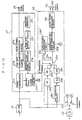
- Fig. 9 shows a block circuit diagram of a sixth embodiment of the present invention.
- a disc 1 is rotated by a spindle motor 2, and data recorded on the disc are read out by pickup 3.
- the pickup 3 includes a laser diode serving as a light source, an optical system including an object lens, a photo-detector for receiving light reflected from disc 1, a focus actuator for controlling the position of the object lens with respect to a data recording surface of disc 1, a tracking actuator etc. for controlling movement of the light spot formed by pickup 3, i.e. the data detection point, along a radial direction of disc 1.
- the output RF signal from the pickup 3 is supplied through an RF amplifier 24, to a focus error signal generating circuit 25 and a tracking error signal generating circuit 26.
- the RF signal from RF amplifier 24 is supplied to a video data demodulation system 27 and to a digital data demodulation system 28.
- the video data demodulation system 27 includes a video demodulator 27a for demodulating the playback RF signal from RF amplifier 24, to produce a video signal, which is supplied to a time axis compensation circuit 27b.
- the time axis compensation circuit 27b includes a variable delay element such as a CCD (Charge Coupled Device), and applies time axis compensation by variation of an amount of time delay in accordance with a control signal which is supplied from a time axis control circuit 27c.
- the time axis control circuit 27c produces a control signal as output, in accordance with a phase difference between an oscillator output signal produced from a quartz crystal oscillator circuit (VCXO 27d) and a signal produced by frequency division of that oscillator output signal, and the horizontal sync signal and color burst signal contained in the video signal after transfer through the time axis compensation circuit 27b.
- the clock signal generating circuit 27d oscillates in synchronism with the horizontal sync signal contained in the video signal from video demodulator 27a.
- a specific example of a configuration for such a time axis compensation circuit is given in Japanese patent Laid-Open No. 56-102182. Detailed description will therefore be omitted.
- the video signal After being subjected to time axis compensation in the time axis compensation circuit 27b in this way, the video signal is transferred through video signal processing circuit 27e, to be supplied to a video signal output terminal 29.
- the video signal processing circuit 27e executes processing which includes video muting (whereby the video signal is selectively inhibited from transfer to output terminal 29), characteristic insertion or blue picture insertion, based upon characteristic data supplied from the character generator 27f.
- the digital data demodulation system 28 includes a selector switch 28a, whose connection status is determined in accordance with the disc area (i.e. CD area of video area) which is being played, during playback of a composite disc.
- the disc area i.e. CD area of video area
- switch 28a is set to the a position thereof, and is set to the b position during playback of a video area.
- Changeover operation of switch 28a is performed in response to a changeover command which is issued from the system controller 47 (described hereinafter).
- the speed of rotation of the disc will differ substantially, depending upon whether the CD area or the video area is being played.
- the PCM audio signal will be, for example, an EFM (Eight to Fourteen Modulation) digital signal, which is superimposed upon an FM modulation video signal at the time of recording the disc. Since the EFM signal has an adverse effect upon the low frequency components of the FM video signal, the EFM signal is recorded at a level which is lower than the video carrier level by several tens of dB, although the degree of modulation is the same for both the EFM and video signals. This is illustrated in Fig. 7. Thus, the frequency characteristic and amplitude of a playback EFM signal will both be different, for the cases of CD area playback and video area playback respectively. However with the present invention, a common demodulated system is used for both forms of EFM signal playback. This is made possible by switching which is applied to the signal processing systems for EFM signals of the CD area and the video area respectively.
- EFM Average Modulation
- the playback RF signal is an EFM signal, which is subjected to frequency characteristic compensation by the equalizer circuit 28b, having a predetermined equalizer characteristic, and is amplified by a predetermined amount of gain by amplifier 28c
- the playback RF signal is an FM video signal which is combined with an EFM signal.
- the EFM signal is extracted from the playback RF signal by an EFM extraction circuit 28d (e.g. a low-pass filter), then is subjected to frequency characteristic compensation by the equalizer circuit 28e, which has a different equalization characteristic from the equalizer circuit 28b, to be then amplified in amplifier 28f, which has a higher gain than that of amplifier 28c.
- an EFM signal is derived whose frequency characteristic and amplitude are identical to those of the EFM signal obtained during CD area playback.
- the selector switch 28a is held in position a .
- the playback EFM signal selected by the selector switch 28a is supplied to demodulation and error correction circuit 28g, which performs demodulation of the EFM signal, and write-in of the demodulated signal to a memory (not shown in the drawings) such as a RAM (random access memory), and also performs control of this RAM based upon a reference clock signal produced from an reference clock signal generating circuit 28h, to perform data operations for executing data interleaving and error checking, by using parity bits contained in the data.
- a memory not shown in the drawings
- a RAM random access memory
- the demodulation and error correction circuit 28g also performs frequency division of the reference clock signal from reference clock signal generating circuit 28h, and frequency division of the frame sync signal which is detected in the EFM signal, and detects the amount of phase difference and frequency difference between the resultant frequency-divided signals.
- the demodulation and error correction circuit 28g thereby produces a spindle error signal, in accordance with these phase and frequency differences, which is supplied to an equalizer circuit 42, and also produces an error-corrected digital audio signal which is processed in an audio signal processing circuit 28i, consisting of a D/A converter, a de-glitcher circuit, etc, and is then supplied to a pair of left and right-channel audio signal channel output terminals 30L and 30R.
- a focus error signal generating circuit 25 serves to detect an amount of deviation in the vertical direction of the light spot which is focussed on the recording surface of disc 1, with respect to that recording surface, and produces a focus error signal by for example utilizing astigmatic aberration.
- the tracking error signal generating circuit 26 serves to detect an amount of deviation of the light spot with respect to the recording surface of disc 1, along the direction of a radius of the disc, and produces a tracking error signal by a known detection method such as the 3-beam method.
- the output signals from the focus error signal generating circuit 25 and the tracking error signal generating circuit 26 are applied to equalizer circuits 31 and 32 respectively, which perform compensation of the frequency characteristics of the respective error signals, and are then transferred to amplifiers 33 and 34 respectively, and then supplied to drivers 35 and 36.
- the resultant outputs from drivers 35 and 36 are drive signals which are respectively supplied to a focus actuator and tracking actuator (not shown in the drawing), which are built-into the pickup 3.
- the speed of rotation of a composite disc is extremely different during playback of a CD area and a video area respectively (as illustrated in Fig. 8).
- the disc acceleration values which are used for focussing and tracking are therefore increased, by comparison with the values which are utilized during CD area playback.
- the equalization characteristics of equalizer circuits 31 and 32 and the gains of amplifiers 33 and 34, used in the focus and tracking servo systems are respectively changed over, for playback of a CD area and a video area respectively.
- This changeover is executed by switching of elements within the respective equalizer circuits and amplifier circuits.
- servo changeover commands are issued by the system controller 47, whereby the equalization characteristics of the equalizer circuits 31 and 32 are changed such as to provide appropriate frequency characteristics for the respective error signals.
- the gains of amplifiers 33 and 34 are respectively increased, to provide the appropriate amplifiers for the respective error signals. In this way, although the frequencies of the respective error signals are increased during video area playback, by comparison with CD area playback, satisfactory focussing and tracking operation are attained in the same way as during CD area playback.
- changeover of the respective equalization characteristics of the equalizer circuits 31 and 32 and of the respective gains of amplifiers 33 and 34 are executed by switching of elements within the circuits 31 to 34.
- the tracking error signal produced from the tracking error signal generating circuit 26 is supplied to an LPF (low-pass filter) 37, to derive the low-frequency components of that signal.
- the low-frequency components are then supplied through equalizer circuits 38 and 39 to driver 40, which thereby produces a drive signal for driving a carriage motor 41.
- the carriage motor 41 constitutes a motive source for a carriage (not shown in the drawings) which moves pickup 3 along a radial direction of disc 1.
- a carriage servo system is thereby configured.
- the spindle error signal produced from the demodulation and error correction circuit 28g in the digital data demodulation system 28 is transferred through equalizer circuit 42 and amplifier 43 to be supplied to driver 44, whereby a drive-signal is produced for driving spindle motor 2 to rotate the disc 1.
- a spindle servo system is thereby configured.
- changeover of the equalization characteristics of equalizer circuits 38 and 42, and the gains of amplifiers 39 and 43 in the carriage servo circuit and spindle servo circuit is executed for playback of the video area and CD area respectively, to thereby ensure stable servo circuit operation during video area playback.
- Changeover of the respective equalization characteristics and gains is executed by switching of elements within the equalizer circuits and amplifier circuits.
- the present embodiment has been described on the assumption that the focus, tracking, carriage and spindle servo systems are all selectively changed in accordance with CD area playback operation and video area playback operation. However in some cases it may be possible in practice to obtain satisfactory results by executing changeover of the equalization characteristic and amplifier gain of only one (but at least one) servo circuit, for example the tracking servo circuit.
- the tracking servo loop is held in the open state, and track jumping by one track at a time is executed by applying kick pulses A and brake pulses B, as shown in Fig. 10(a), to the tracking actuator.
- kick pulses A and brake pulses B as shown in Fig. 10(a)
- track jumping over a number of tracks at one time e.g. 10 to 100 tracks, is executed by applying a pulse C to the carriage motor 41 in addition to the pulses A and B applied to the tracking actuator, as is well known in the art.
- the kick pulses A, brake pulses B and drive pulses C are produced by the system controller 47, and are supplied to the drivers 36 and 40 .
- Fig. 10(b) shows the waveform of the tracking error signal as the light spot of pickup 3 moves laterally across one track.
- pulses A, B and C are respectively changed over for CD area and video area playback operation, in accordance with the different speeds of disc rotation which are used. Specifically, if there is disc eccentricity, then since the speed of rotation of the disc during video area playback is high, the time required to complete each jump operation must be made shorter than in the case of CD area playback, in order to reduce the adverse effects of disc eccentricity. For this reason, the widths a, b and c of pulses A to C respectively are made greater during video area playback than during CD area playback, to thereby increase the amount of drive power which is supplied to the tracking actuator and the carriage motor 41 during each pulse.
- the determination of the widths of pulses A, B and C and changeover of the pulse widths between CD area and video area playback operation respectively can be easily implemented by the microcomputer which constitutes the system controller 47. Instead of performing changeover of the respective widths of pulses A, B, and C, it would be equally possible as shown in Fig. 12, to vary the peak amplitudes d and e (shown in Figs. 10 and 11) in accordance with video area and CD area playback. This can be accomplished as shown by using changeover switches 34a and 34b, to select the appropriate peak values of pulses A, B and C respectively, to be supplied to the tracking actuator and to the carriage motor 41.
- the assignee of the present invention has found from practical experiments that optimum operation can be obtained during single-track jumping, by making the peak value d of kick pulses A and brake pulses B larger during video area playback than during CD area playback, and making the pulse width of the brake pulses B more narrow during video area operation than during CD area operation.
- the position detector 46 serves to detect when the light from pickup 3 reaches a position corresponding to the boundary between the CD area and the video area of a composite disc, as pickup 3 moves radially across the disc, and produces a corresponding detection signal. This signal indicates that the pickup 3 has reached the video area. Since the position detector 46 functions to detect the position of pickup 3 during movement of the pickup, it is undesirable that position detector 46 should apply a load to pickup 3, and should therefore preferably consist of a combination of a photo-emissive and a photo-receptive element, with light from the photo-emissive element being transmitted to (or shielded from) the photo-receptive element when the pickup 3 attains a predetermined position.
- the position detector 46 can consist of a reflective or transmissive type of photo-coupler.
- the position detector 46 can include a slider form of potentiometer which is coupled to move with pickup 3, and which produces an output signal in accordance with the amount of displacement of pickup 3, together with a converter which receives the output signal from the potentiometer and compares that signal with a reference value signal, to produce an output signal indicating that the pickup 3 has reached a predetermined position when the potentiometer output signal coincides with the reference value signal.
- the sensing position can for example be the position at which the light spot of pickup 3 reaches the audio lead-out area shown in Fig.
- the boundary between the audio lead-out area and the video lead-in area a position which is within the video lead-in area, the boundary between the video lead-in area and the video program area, or a position within the video program area.
- the sensing position be made an intermediate position within the video lead-in area.
- the detection signal produced from position detector 46 is supplied to the system controller 47.
- the system controller 47 also receives disc designation data from the operating section 48, which indicates whether the disc to be played is a CD or a composite disc, as well as mode designation data which indicates (during playback of a composite disc) whether playback of the CD area alone, playback of the video area alone, or playback of both of these regions is to be performed. Selection of this mode designation data can be performed, for example, by toggle operation of a tactile switch or changeover operation of a slider switch or pushbutton switch, provided in the operating section 48. Alternatively, selection of the mode designation data can be performed by remote control, irrespective of the operating section 48, e.g. by using a wireless remote control unit or a wired remote control unit.
- system controller 47 Since the system controller 47 is based on a microcomputer, it executes various functions, including interchange of data between the video data demodulation system 27 and the digital data demodulation system 28 via a bus 45, and also generates changeover commands for selector switch 28a of the digital data demodulation system 28 and for the equalizer circuits and amplifiers of the respective servo systems, in accordance with detection signals from the position detector 46.
- the system controller 47 also generates commands for driver 50 of motor 59, which is the motive source for a loading mechanism (not shown in the drawings) which executes automatic transfer of a disc between a disc entry aperture in the outer case of the playback apparatus and the disc playing position.
- the system controller 47 also is supplied with FG (Frequency Generator) pulses which are produced by a frequency generator 52 that is coupled to the spindle motor 2.
- FG Frequency Generator
- the system controller 47 counts a number of clock pulses having a specific frequency, which occur within one period between successive FG pulses, and computes the speed of rotation of the spindle motor 2 (i.e. the speed of rotation of disc 1) based upon this count value and the clock pulse frequency.
- the demodulation and error correction circuit 28g of digital data demodulation system 28 irrespective of the area of the composite disc which is being played, the demodulation and error correction circuit 28g of digital data demodulation system 28 generates a spindle error signal in accordance with the phase difference between the frame sync signal within the EFM signal and a reference clock signal, and controls the speed of rotation of spindle motor 2 based upon this error signal.
- the configuration is such that control of the rotation of spindle motor 2 is executed in accordance with an error signal produced from the demodulation and error correction circuit 28g of digital data demodulation system 28, during CD area playback, while control of spindle motor 2 rotation is executed in accordance with a phase difference between the horizontal sync signal in the video signal and a reference horizontal sync signal during video area playback.
- the time axis control circuit 27c' of a video data demodulation system 27' controls a time axis compensation circuit 27b in accordance with a phase difference between a reference horizontal sync signal produced from the reference sync signal generating circuit 27g and a playback horizontal sync signal which is separated from the video signal.
- the spindle error signal generating circuit 27h performs phase comparison between the horizontal sync signal separated from the video signal (prior to application of time axis compensation to the video signal) and the reference horizontal sync signal, to derive the phase difference between these sync signals, and produces a phase difference signal which is supplied as a spindle error signal to one input of the changeover switch 53.
- a changeover switch 28j is set to the a position thereof during CD area playback, and to the b thereof during video area playback, under the control of a cchangeover command from the system controller 47.
- a clock signal generating circuit 28h' of digital signal processing system 28' is controlled by the output from switch 28j to generate a reference clock signal having a predetermined frequency during CD area playback, and a clock signal which is synchronized with the playback clock signal contained in the EFM signal, during video area playback.
- Error correction etc, are performed on the basis of the clock signal which is produced from 28h', while in addition the differences in frequency and phase between the reference clock signal and the frame sync signal during CD area playback are used to derive a spindle error signal which is supplied to the other input of switch 53.
- the switch 53 is controlled by a changeover command from system controller 47 such as to be set to the a position thereof during CD area playback, and to the b position during video area playback.
- Spindle servo control is executed based on the spindle error signal which is derived by the demodulation and error correction circuit 28g of the digital data demodulation system 28, during CD area playback, and an spindle error signal determined by the phase difference between the playback horizontal sync signal and a reference horizontal sync signal during video area playback.
- a composite disc includes a CD area and a video area, with each of these regions having a lead-in area.
- Each lead-in area includes a TOC (table of contents) recorded therein, which expresses the program contents of that area.
- the TOC of an audio area includes data which indicates whether or not the disc is a composite disc.
- the NTSC standard is used as a color television standard mainly in Japan and the U.S.A.
- the PAL standard is used mainly in European countries. Both of these standards are utilized in composite discs, and therefore the TOC of an audio lead-in area indicates whether the disc contains data in accordance with the NTSC standard or the PAL standard. Basically, NTSC standard composite discs must be played on NTSC standard playback apparatus, while PAL standard composite discs must be played on a PAL standard playback apparatus.
- a start command is issued from the operating section 48, then firstly the carriage motor 41 is activated to move pickup 3 to the innermost peripheral position of the disc recording area (step 1).
- a sensor switch is provided for sensing when this innermost peripheral position has been reached, and when this is sensed, focussing of pick-up 3 is performed.
- the TOC data of the lead-in area at the disc inner periphery is then read in (step 2). After completion of playback of the lead-in area, a judgement is made as to whether or not the TOC data has been read in.
- step 3 If it is judged in step 3 that the TOC data has been read in, then the processor judges whether or not the disc is a composite disc, based upon the contents of the TOC. (step 4). A decision is then made as to whether or not the disc is an NTSC standard disc (step 5).
- step 6 If the disc is found not to be a composite disc in step 4, then since this indicates that the disc must be a CD disc, operation is changed to the CD play mode (step 6). If it is judged in step 5 that the disc is a NTSC type, then operation changes to the NTSC standard composite disc play mode (step 7). On the other hand, If it is judged in step 5 that the disc is not of NTSC standard, then operation moves to the PAL standard composite disc play mode (step 8). Furthermore, if it is found in step 3 that the TOC data could not be read, e.g.
- the disc to be played is a composite disc, and the composite disc play mode is entered (step 9).
- an operating sequence is executed, as shown in flow charts described hereinafter.
- the playback operation of the CD play mode (step 6) is well known, and therefore description of this will be omitted.
- step 10 Upon completion of the sequence of operations of a play mode, execution returns to the main program flow, and A decision is then made as to whether or not playback of all of the program data has been completed (step 10). If data playback has been completed, then the carriage motor 41 is driven to move the pickup to its home position, (step 11), and loading motor 49 is driven whereby a loading mechanism (not shown in the drawings) performs disc ejection (step 12). This completes the operating sequence.
- Playback operation in the NTSC standard composite disc play mode (step 7) will be described referring to the flow chart of Fig. 15.
- the area (or areas) of the disc which is required to be played is designated by the user, e.g. by actuation of a switch on operating section 48.
- a decision is made as to whether the video area alone is to be played, with this decision being made in accordance with mode designation data which are supplied from the operating section 48.
- This data may designate playback of only the CD area, playback of only the video area, or playback of both the video area and the CD area (step 20) . If playback of the video area alone is not designated, then CD area playback is initiated (step 21).
- step 22 the processor judges whether or not playback of the CD area alone is designated, based on the mode designation which is then read in (step 23). If CD area playback alone is designated, then execution returns to the main flow, shown in Fig. 14. It should be noted that if CD area playback alone is designated, then search, scan, program play, and repeat operations, etc., will only be possible within the CD area.
- step 23 If it is judged in step 23 that playback of the CD area alone is not designated, then this signifies that playback of both the video area and CD area is designated, and therefore the spindle motor 2 is accelerated towards the maximum rated speed of rotation (stem 24).
- step 25 When it is detected that the data sensing light spot of pickup 3 has reached a specific position, e.g. a central position in the video lead-in area, (this detection being based on a detection output from pposition detector 46) (step 25), read-in of the video TOC data from that lead-in area is initiated (step 26), then the processor judges whether or not the TOC data has been read in (step 27).
- step 26 If it is judged in step 26 that this data has not been read in, then this is judged to indicate that the position at which the data detection point has halted is past the video lead-in area.
- the tracking actuator of pickup 3 is then driven to execute a jump back by the data detection point over a predetermined number of tracks (step 28). Execution then returns to step 26, and read-in of the playback TOC data is again attempted. Steps 26, 27, and 28 are repetitively performed until it is judged in step 27 that the TOC data has been read in. When this occurs, execution moves to video area playback operation (step 29). Both an FM modulated video signal and a PCM audio signal superimposed thereon are recorded in the video area, and both of these signals are played back during video area playback.
- search, scan, program play, and repeat operations, etc. can be carried out for the CD area alone, or for the video area alone.
- search operations extending from the CD area through the video area, or extending from the video area through the CD area can also be performed, as also can a "repeat" operation applied to both of these areas (i.e. with the program contents of both the video area and CD area being repeated.
- step 20 If it is judged in step 20 that playback of only the video area is designated, then the spindle motor 2 is accelerated to its maximum rated speed of rotation for video area playback (step 30 ).
- step 31 the carriage motor 41 is driven for accelerated rotation, whereby pickup 3 is moved at high speed towards the video lead-in area (step 31). Execution then moves to step 25. If playback of only the video area is designated, then search, scan, program play, and repeat operations, etc., can be carried out only within the video area.
- control (address) data read-in from the video area is performed by using Q-channel data of a CD format sub-code signal, then since as described hereinabove an EFM signal is recorded in the video area at a level sufficiently lower than that of the video carrier level (see Fig. 1), the data read error rate during read-out of this control data will be approximately three times as high as during CD area playback.
- data obtained during first, second and third successive read operations are designated as A, B and C respectively.
- the addresses at which the data thus read in are successively stored are increased by one, each time new data are read in.
- step 45 sensing of a detection signal produced from position detector 46 is performed. If it is judged in step 45 that the light spot of pickup 3 is within the video area, a decision is then made as to whether or not servo control is to be applied to the spindle motor in accordance with a spindle error signal derived on the basis of the frame sync signal of the EFM signal produced by demodulation and error correction circuit 28g of digital data demodulation system 28 (step 46).
- servo control will be referred to in the following simply as EFM servo control.
- step 47 changeover to EFM servo control is executed (step 47). More specifically, in the playback apparatus embodiment shown in Fig. 9, the spindle servo system is placed under EFM servo control, irrespective of the playback area of the disc, whereas in the case of the playback apparatus embodiment of Fig. 13, EFM servo control is only applied during playback of the CD area, while during playback of the video area, spindle servo control is executed in accordance with a spindle error signal which is derived based on the regenerated horizontal sync signal produced from video data demodulation system 27' (this form of spindle servo control will be referred to in the following as video servo control). Changeover between EFM servo control and video servo control is automatically carried out. In the case of the embodiment of Fig. 13, a changeover operation can be executed to place the spindle servo system under EFM servo control.
- muting is applied to the video output signal from video signal processing circuit 27e, and only the audio data are output (step 48). Also, at this time, an indication is produced on display unit 51, which signifies that a PAL standard composite disc has been inserted into an NTSC standard playback apparatus (step 49). Execution then returns to the main flow shown in Fig.. 14.
- the display unit 51 can for example employ light-emitting diodes which are caused to flash. However the invention is not limited to such an arrangement. Alternatively, rather than producing an indication on display unit 51, an indication in the form of character data, for example, can be produced on a television monitor (not shown in the drawings).
- step 9 of Fig. 14 The playback operation sequence for the case in which the composite disc play mode is selected (in step 9 of Fig. 14) will be described, with reference to the flow chart of Fig. 17.
- a decision is then made as to whether or not playback of the video area alone has been designated, with this decision being based on the mode designation data from operating section 48, which can designate playback of the CD area alone, playback of the video area alone, or playback of both of these (step 60). If it is judged in step 60 that playback of the video area alone is not designated, then execution moves to CD area playback operation (step 61). During playback of the CD area, playback of audio data will of course be performed.
- a "blue picture” may also be produced to be displayed on a television monitor (not shown in the drawings), based on "blue picture” data produced from character generator 27f, as a result of signal switching operations executed by video signal processing circuit 27e of video data demodulation system 27. DUring this CD area playback, a decision is then made as to whether or not playback of the video area alone has been designated, i.e. from the operating section 48. If this does not occur, then execution returns to step 22 of the flow shown in Fig. 15.
- step 63 If video area playback is designated while CD area playback is in progress, or if it is judged in step 16 that playback of the video area alone has been designated, then the spindle motor 2 is accelerated towards the maximum rated speed of rotation for the video area (step 63). At the same time, motor 41 is set in high-speed rotation, to move the pickup 3 rapidly towards the video lead-in area (step 64). A decision is then made as to whether or not the position detector 46 has issued a detection signal which indicates that the video area has been reached by the light spot (step 65), and then the processor judges whether or not the spindle servo loop has attained the lock-in status (step 66). If lock-in has been achieved, then execution moves to step 26 of the flow shown in Fig.. 15. The spindle servo lock-in condition is detected by the spindle servo system (for example as described in Japanese Utility Model Laid-Open No. 57-134774), which thereupon supplies a lock-in detection signal to the system controller 47.
- the predetermined position can be the position of the data detection point at the time when a change to video area playback was designated.
- the position could be the start of the musical item which was being played when the change was designated, or the start of the musical item which immediately succeeds the item which was being played when the change was designated, or (if the musical item being played at the time of change designation was the last item of the CD area) the predetermined position can be made the start of the first musical item of the CD area.
- the playback apparatus could be set in a "stop" condition.
- the playback apparatus preferably includes means whereby, in the event that it is proved that the disc being played is a CD disc, subsequent designations of video area playback are ignored.
- the display appearing on the television monitor will change from the playback video picture to the "blue picture".
- the vertical sync signal of the playback video signal and the vertical sync signal of the video signal of the "blue picture” (the latter video signal being referred to in the following gas the blue video signal) will in general not be mutually synchronized in phase, so that the blue picture produced on the monitor will appear disordered.
- the system controller 47 first acts to monitor a specific edge of the vertical sync signal pulses in the playback video signal (step 80), and then resets the character generator 27f (shown in Fig. 9) which generates the blue video signal, when that vertical sync signal pulse edge is detected.
- the vertical sync signal of the playback video signal and the vertical sync signal of the "blue picture” are sunchronized in phase.
- the term "synchronized in phase” has the significance that specific edges (e.g.
- Figs. 20(a), (b) and (c) are waveform diagrams showing the phase relationships between the horizontal sync signal of the playback video signal, the vertical sync signal of the playback video signal, and the vertical sync signal of the blue picture signal, respectively.
- I denotes a number of horizontal sync pulses which occur during an interval between a falling edge of a playback video vertical sync pulse and the next falling edge of a blue video vertical sync pulse.
- I o denotes a number of horizontal sync pulses which occur during an interval between the falling edges of two successive playback video vertical sync pulses.
- phase synchronization is achieved by adding or subtracting specific numbers of horizontal sync pulses to or from the blue video vertical sync signal, in four stages.
- a, b, c and d respectively denote numbers of horizontal sync pulses which are added or subtracted, while A, B, C and D denote numbers of times that an operation of adding (or subtracting) a, b, c and d pulses respectively is repeated.
- the numbers of pulses a, b, c and d, and the numbers of repetitions A, B, C and D are respectively predetermined and are stored in a memory of the microcomputer of operating section 48.
- step 83 the processor judges whether or not I ⁇ I o /2 , i.e. judges whether the time interval between a falling edge of a playback video vertical sync pulse and the next falling edge of a blue video vertical sync pulse is greater than 1/2 of the interval between two successive falling edges of the playback video vertical sync signal (step 84).
- Step 86 is then executed (with a "no" decision) and a pulses are subtracted (step 87).
- the value of A is reduced by one (step 88).
- step 93 is executed, and c horizontal sync pulses are subtracted (step 94), while in addition the value of C is reduced by one (step 95).
- step 84 If it is judged in step 84 that I ⁇ I o /2, then horizontal sync pulses must be added to the blue picture vertical sync signal.
- the operating flow to perform this can be the same as that of Fig. 21 (i.e. steps 85 through 96), but with a pulse addition operation being executed in each of steps 87, 91, 94 and 97, instead of a subtraction operation.
- the number of pulses which is added or subtracted is gradually increased and gradually decreased. Furthermore, the maximum number of horizontal sync pulses which is added or subtracted at one time must be held within a limit which will not result in a disordered picture, e.g. approximately 10 pulses.
- detection of the condition in which the light spot of pickup 3 has reached the video area is performed on the basis of a detection signal produced from position detector 46.
- the video carrier is separated from the playback RF signal by means of a bandpass filter 60, and the peak amplitude of the video carrier is held in a peak holding circuit 61, to be compared with a reference level by a comparator 62.
- the passband of filter 60 should be of the form indicated by the chain-line outline in Fig. 23, in order to pass the luminance signal component C of the FM modulated video signal.
- A denotes the PCM audio signal.
- a playback digital signal is obtained whose frequency characteristic and amplitude are identical both for the case of playback of the CD area and playback of the video area, and a single demodulation system can be used in common for digital playback signals produced during both playback of the CD area and of the video area, thereby enabling the manufacturing cost of the apparatus to be lowered.
- a data recording disc playback apparatus With a data recording disc playback apparatus according to the present invention, changeover of the equalization characteristic and loop gain of at least one of the servo systems of the apparatus is performed during playback of a composite disc, in accordance with playback of the video area and playback of the CD area respectively, whereby an error signal having an identical frequency characteristic and amplitude is supplied to that servo system during both CD area and video area playback.
- changeover of the equalization characteristic and loop gain of at least one of the servo systems of the apparatus is performed during playback of a composite disc, in accordance with playback of the video area and playback of the CD area respectively, whereby an error signal having an identical frequency characteristic and amplitude is supplied to that servo system during both CD area and video area playback.
- a spindle servo circuit is used to control a spindle notor, to thereby control the velocity of displacement of a data sensing light spot with respect to a disc.
- the scope of the invention also covers the application of such control to a tangential servo circuit which controls a tangential mirror or a tangential actuator.
- a data recording disc playback apparatus when a track jump operation is executed during playback of a composite disc, changeover of at least one of the peak amplitude and pulse width of drive pulses applied to a tracking actuator and to a carriage motor is executed, in accordance with playback of the video area and the CD area of the disc, respectively.
- changeover of at least one of the peak amplitude and pulse width of drive pulses applied to a tracking actuator and to a carriage motor is executed, in accordance with playback of the video area and the CD area of the disc, respectively.
- the speed of rotation of the disc differs substantially for playback of these respective areas, a satisfactory degree of track jump control is attained during playback of both the video area and the CD area.
- a data playback method detection of the video area of a composite disc is performed by utilizing a position detector. After the data sensing light spot position has been detected by using this position detector, reading of recorded data is executed, and the position of the light spot is then controlled such as to move to a position within the video lead-in area, with the latter control being executed on the basis of the data which has been read from the disc. In this way, playback is made to reliably begin from the lead-in area, so that the adverse effects of detection errors generated by the position detector, dimensional variations etc. between different discs, or position overshoot by the carriage, are substantially suppressed.
- a data recording disc playback apparatus when a composite disc having a color television standard which does not conform to that of the playback apparatus is set into the apparatus, spindle servo control is executed on the basis of a phase difference between the playback clock signal contained in a playback digital signal and a reference clock signal, during video area playback, with the playback video signal being muted and only the digital signal component of the video area being produced as output.
- the composite disc standard is different from that of the apparatus, playback of at least audio data from the video area can be achieved, thereby enhancing the value of such an apparatus to the user.
- an indication is provided to the user that the television standard of the disc does not conform to that of the playback apparatus, so that the user is notified of the reason why video playback is not possible.
- disc rotational speed control is performed on the basis of a playback clock signal which is obtained from the playback digital signal, so that even if the color television standard of the video data is different from that of the playback apparatus, playback of audio data is reliably achieved, since the CD format is common to all discs. In addition, playback of video data in black and white will be possible.
Applications Claiming Priority (17)
| Application Number | Priority Date | Filing Date | Title |
|---|---|---|---|
| JP86715/86 | 1986-04-15 | ||
| JP8671486A JPH073732B2 (ja) | 1986-04-15 | 1986-04-15 | 情報記録デイスク再生装置 |
| JP86716/86 | 1986-04-15 | ||
| JP61086716A JPH0714222B2 (ja) | 1986-04-15 | 1986-04-15 | ディスク記録情報再生装置 |
| JP61086711A JPH077523B2 (ja) | 1986-04-15 | 1986-04-15 | 情報読取装置 |
| JP8671986A JPH0648577B2 (ja) | 1986-04-15 | 1986-04-15 | 情報再生方式 |
| JP61086722A JPH0610919B2 (ja) | 1986-04-15 | 1986-04-15 | 情報記録デイスク再生装置 |
| JP8671286A JPS62243168A (ja) | 1986-04-15 | 1986-04-15 | 情報記録デイスク再生装置 |
| JP86711/86 | 1986-04-15 | ||
| JP86713/86 | 1986-04-15 | ||
| JP8671586A JPH0715781B2 (ja) | 1986-04-15 | 1986-04-15 | 情報再生方法 |
| JP86714/86 | 1986-04-15 | ||
| JP8671386A JPH065578B2 (ja) | 1986-04-15 | 1986-04-15 | 情報記録デイスク再生装置 |
| JP86712/86 | 1986-04-15 | ||
| JP86719/86 | 1986-04-15 | ||
| JP86722/86 | 1986-04-15 | ||
| EP87303360A EP0242215B1 (fr) | 1986-04-15 | 1987-04-15 | Appareil pour reproduire un disque d'enregristrement numérique |
Related Parent Applications (1)
| Application Number | Title | Priority Date | Filing Date |
|---|---|---|---|
| EP87303360.9 Division | 1987-04-15 |
Publications (3)
| Publication Number | Publication Date |
|---|---|
| EP0500149A2 true EP0500149A2 (fr) | 1992-08-26 |
| EP0500149A3 EP0500149A3 (en) | 1992-12-23 |
| EP0500149B1 EP0500149B1 (fr) | 1994-09-21 |
Family
ID=27572791
Family Applications (5)
| Application Number | Title | Priority Date | Filing Date |
|---|---|---|---|
| EP92107743A Expired - Lifetime EP0500149B1 (fr) | 1986-04-15 | 1987-04-15 | Appareil pour reproduire un disque d'enregistrement numérique |
| EP92107742A Expired - Lifetime EP0500148B1 (fr) | 1986-04-15 | 1987-04-15 | Appareil pour reproduire un disque d'enregistrement numérique |
| EP19920107745 Withdrawn EP0499295A3 (en) | 1986-04-15 | 1987-04-15 | Method and apparatus for data recording disc playback |
| EP92107746A Expired - Lifetime EP0501528B1 (fr) | 1986-04-15 | 1987-04-15 | Méthode pour reproduire un disque d'enregistrement numérique |
| EP87303360A Expired - Lifetime EP0242215B1 (fr) | 1986-04-15 | 1987-04-15 | Appareil pour reproduire un disque d'enregristrement numérique |
Family Applications After (4)
| Application Number | Title | Priority Date | Filing Date |
|---|---|---|---|
| EP92107742A Expired - Lifetime EP0500148B1 (fr) | 1986-04-15 | 1987-04-15 | Appareil pour reproduire un disque d'enregistrement numérique |
| EP19920107745 Withdrawn EP0499295A3 (en) | 1986-04-15 | 1987-04-15 | Method and apparatus for data recording disc playback |
| EP92107746A Expired - Lifetime EP0501528B1 (fr) | 1986-04-15 | 1987-04-15 | Méthode pour reproduire un disque d'enregistrement numérique |
| EP87303360A Expired - Lifetime EP0242215B1 (fr) | 1986-04-15 | 1987-04-15 | Appareil pour reproduire un disque d'enregristrement numérique |
Country Status (3)
| Country | Link |
|---|---|
| US (1) | US4761692A (fr) |
| EP (5) | EP0500149B1 (fr) |
| DE (4) | DE3750413T2 (fr) |
Cited By (1)
| Publication number | Priority date | Publication date | Assignee | Title |
|---|---|---|---|---|
| EP0598411A1 (fr) * | 1992-11-18 | 1994-05-25 | Sony Corporation | Procédé d'enregistement d'un disque et dispositif d'ajustement du point d'interruption des données audio |
Families Citing this family (47)
| Publication number | Priority date | Publication date | Assignee | Title |
|---|---|---|---|---|
| US4872068A (en) * | 1987-01-28 | 1989-10-03 | Pioneer Electronic Corporation | Disk playing method resulting in reduced start-up time |
| JPH0821214B2 (ja) * | 1987-02-27 | 1996-03-04 | パイオニア株式会社 | デイスク再生方式 |
| JPS63282958A (ja) * | 1987-05-15 | 1988-11-18 | Pioneer Electronic Corp | ディスク再生装置 |
| US5146347A (en) * | 1987-05-29 | 1992-09-08 | Pioneer Electronic Corporation | Disc player control system for quickly placing disc player in command ready state |
| US5166921A (en) * | 1987-06-17 | 1992-11-24 | Pioneer Electronic Corporation | Optical disk carrying tracking information in multiple formats and apparatus for analyzing same |
| JP2565238B2 (ja) * | 1987-10-15 | 1996-12-18 | ソニー株式会社 | 光学式ディスク再生装置 |
| EP0347511A3 (en) * | 1987-11-19 | 1990-11-14 | Kurt Matthys | Video disc with a supplementary audio and signal track |
| JP2834734B2 (ja) * | 1987-12-18 | 1998-12-14 | シャープ株式会社 | 光ディスクの情報記録方法 |
| JPH01164279A (ja) * | 1987-12-19 | 1989-06-28 | Pioneer Electron Corp | スピンドルモータの停止制御装置 |
| US5781689A (en) * | 1987-12-28 | 1998-07-14 | Canon Kabushiki Kaisha | Apparatus for reproducing audio and image signals from different areas of a medium |
| JP2524795B2 (ja) * | 1988-02-12 | 1996-08-14 | パイオニア株式会社 | ディスク再生装置 |
| JP2811445B2 (ja) * | 1988-03-22 | 1998-10-15 | パイオニア株式会社 | 画像情報の記録方法及び再生方法 |
| JP2683021B2 (ja) * | 1988-04-04 | 1997-11-26 | パイオニア株式会社 | 画像情報再生処理装置 |
| US5016113A (en) * | 1988-04-04 | 1991-05-14 | Pioneer Electronic Corporation | Apparatus for reproducing and processing picture information including graphic codes from a recording medium |
| US5103317A (en) * | 1988-04-25 | 1992-04-07 | Pioneer Electronic Corporation | Apparatus for playing recording medium having a selective special reproduction playback mode |
| JPH01273268A (ja) * | 1988-04-25 | 1989-11-01 | Pioneer Electron Corp | 情報記録再生方法 |
| JPH01273270A (ja) * | 1988-04-25 | 1989-11-01 | Pioneer Electron Corp | 記録媒体の演奏装置における演奏方式及び情報記録再生方式 |
| JPH01312773A (ja) * | 1988-06-10 | 1989-12-18 | Pioneer Electron Corp | スピンドルモータの停止制御方法 |
| JPH02152015A (ja) * | 1988-12-05 | 1990-06-12 | Pioneer Electron Corp | プリグルーブ付光ディスク及びこれを用いた記録方式 |
| US5161034A (en) * | 1989-07-18 | 1992-11-03 | Wnm Ventures Inc. | Branching table for interactive video display |
| JPH03130972A (ja) * | 1989-10-16 | 1991-06-04 | Matsushita Electric Ind Co Ltd | トラック検索装置及びトラッキング制御装置 |
| JPH03134865A (ja) * | 1989-10-19 | 1991-06-07 | Pioneer Electron Corp | 情報記録ディスク演奏装置 |
| DE69118421T2 (de) * | 1990-02-01 | 1996-09-12 | Matsushita Electric Ind Co Ltd | Gerät zur Wiedergabe von Daten, um eine hohe Übertragungsgeschwindigkeit zu realisieren |
| JPH04323982A (ja) * | 1991-04-23 | 1992-11-13 | Sharp Corp | 記録再生装置 |
| JPH0512784A (ja) * | 1991-07-03 | 1993-01-22 | Pioneer Electron Corp | デイスクプレーヤにおける信号フオーマツト識別方法 |
| US5715224A (en) * | 1991-07-05 | 1998-02-03 | Sony Corporation | Recording medium with synthesis method default value and reproducing device |
| JP3074877B2 (ja) * | 1991-11-22 | 2000-08-07 | ソニー株式会社 | 光ディスクプレーヤ |
| US5592446A (en) * | 1993-06-14 | 1997-01-07 | Sony Corporation | Dual mode recording and reproducing apparatus having two recording regions using differing reproduction principles |
| KR0129989B1 (ko) * | 1993-06-30 | 1998-10-01 | 김광호 | 자동 음색 조정방법 및 장치 |
| KR0132972B1 (ko) * | 1994-11-28 | 1998-04-18 | 배순훈 | 광자기디스크의 서보제어장치 |
| EP0758125B1 (fr) * | 1995-08-09 | 2002-01-23 | Sony Corporation | Milieu d'enregistrement, appareil d'enregistrement et appareil de lecture |
| JP3674092B2 (ja) * | 1995-08-09 | 2005-07-20 | ソニー株式会社 | 再生装置 |
| KR100205425B1 (ko) * | 1995-11-21 | 1999-07-01 | 구자홍 | 광 디스크의 기록재생장치 및 방법 |
| TW320811B (fr) * | 1996-04-12 | 1997-11-21 | Sony Co Ltd | |
| US6011765A (en) * | 1996-04-12 | 2000-01-04 | Sony Corporation | Recording medium having copying protection signals recorded in superposition on main signals |
| JPH1064182A (ja) * | 1996-08-20 | 1998-03-06 | Sony Corp | 記録再生装置および方法 |
| JPH10198965A (ja) * | 1997-01-10 | 1998-07-31 | Sony Corp | 光ディスク再生方法及び光ディスク再生装置 |
| US6741796B1 (en) * | 1997-03-25 | 2004-05-25 | Samsung Electronics, Co., Ltd. | DVD-Audio disk, and apparatus and method for playing the same |
| JP3376265B2 (ja) * | 1997-12-25 | 2003-02-10 | 株式会社東芝 | 複数コンテンツのオブジェクト共有化システム |
| JPH11265563A (ja) | 1998-03-16 | 1999-09-28 | Pioneer Electron Corp | 情報記録媒体及び情報再生装置 |
| DE10030841A1 (de) * | 2000-06-23 | 2002-01-03 | Mannesmann Vdo Ag | Audiogerät zum Abspielen komprimierter und unkomprimierter Audiodateien |
| US7171156B2 (en) * | 2001-08-13 | 2007-01-30 | Thomson Licensing | Method and apparatus for transmitting audio and non-audio information with error correction |
| US7362671B2 (en) * | 2001-08-13 | 2008-04-22 | Sony Corporation | Optical disc recording and/or playing apparatus and method |
| KR100521916B1 (ko) * | 2002-08-21 | 2005-10-13 | 엘지전자 주식회사 | 광디스크 장치에서의 가사 동기 및 오디오신호 전송방법 |
| KR100422374B1 (ko) * | 2003-02-04 | 2004-03-10 | 디브이에스 코리아 주식회사 | 광디스크 드라이브 장치의 재생 제어 방법 및 그 광디스크드라이브 장치 |
| JP2005203057A (ja) * | 2004-01-19 | 2005-07-28 | Funai Electric Co Ltd | 光ディスク記録再生装置 |
| JP4569306B2 (ja) * | 2005-02-02 | 2010-10-27 | 船井電機株式会社 | 光ディスク装置及びデフォーカス調整方法 |
Citations (3)
| Publication number | Priority date | Publication date | Assignee | Title |
|---|---|---|---|---|
| FR2506981A1 (fr) * | 1981-06-01 | 1982-12-03 | Victor Company Of Japan | Agencement de circuit destine a un electrophone pour la reproduction d'informations enregistrees prealablement sous la forme de microcuvettes |
| FR2545970A1 (fr) * | 1983-05-12 | 1984-11-16 | Victor Company Of Japan | Appareil de lecture de support d'enregistrement rotatif |
| EP0174666A2 (fr) * | 1984-09-14 | 1986-03-19 | Pioneer Electronic Corporation | Procédé et appareil pour la reproduction de données de disques d'enregistrement |
Family Cites Families (18)
| Publication number | Priority date | Publication date | Assignee | Title |
|---|---|---|---|---|
| FR1354910A (fr) * | 1963-01-24 | 1964-03-13 | Teverama Sa | Procédé d'enregistrement et de reproduction d'images cinématographiques et support d'un tel enregistrement |
| JPS55139641A (en) * | 1979-04-17 | 1980-10-31 | Matsushita Electric Ind Co Ltd | Optical reproducing device |
| JPS56102182A (en) | 1980-01-18 | 1981-08-15 | Pioneer Video Corp | Time axis correction device for video regenerative signal |
| JPS5798139A (en) * | 1980-12-09 | 1982-06-18 | Fujitsu Ltd | Optical recorder and reproducer |
| JPS6317071Y2 (fr) | 1981-02-17 | 1988-05-16 | ||
| JPS5924475A (ja) * | 1982-07-31 | 1984-02-08 | Matsushita Electric Ind Co Ltd | 再生装置 |
| JPH0675349B2 (ja) * | 1982-11-29 | 1994-09-21 | シャープ株式会社 | ディスクプレ−ヤ |
| JPS59110082A (ja) * | 1982-12-13 | 1984-06-25 | Sharp Corp | ビデオデイスク装置 |
| JPS59121668A (ja) * | 1982-12-28 | 1984-07-13 | Toshiba Corp | デイスクレコ−ド再生装置 |
| JPS59146280A (ja) * | 1983-02-09 | 1984-08-22 | Pioneer Electronic Corp | 記録情報再生装置における同期制御方式 |
| JPS601650A (ja) * | 1983-06-17 | 1985-01-07 | Victor Co Of Japan Ltd | 情報信号記録円盤再生装置 |
| JPS6042992A (ja) * | 1983-08-19 | 1985-03-07 | Victor Co Of Japan Ltd | 情報信号記録円盤 |
| JPH0828054B2 (ja) * | 1983-11-30 | 1996-03-21 | ソニー株式会社 | デイスク状記録媒体 |
| JPS60197979A (ja) * | 1984-03-19 | 1985-10-07 | Sharp Corp | ビデオデイスクプレ−ヤ |
| JPS60226077A (ja) * | 1984-04-24 | 1985-11-11 | Matsushita Electric Ind Co Ltd | トラツキング制御装置 |
| JPS6171472A (ja) * | 1984-09-14 | 1986-04-12 | Pioneer Electronic Corp | 記録デイスク演奏装置 |
| JPS6174174A (ja) * | 1984-09-19 | 1986-04-16 | Asahi Optical Co Ltd | サ−ボ回路の利得自動調整回路 |
| JPH0640393B2 (ja) * | 1985-04-05 | 1994-05-25 | 株式会社日立製作所 | トラッキング制御回路及びこれを用いた光ディスク装置 |
-
1987
- 1987-04-14 US US07/038,358 patent/US4761692A/en not_active Expired - Fee Related
- 1987-04-15 EP EP92107743A patent/EP0500149B1/fr not_active Expired - Lifetime
- 1987-04-15 EP EP92107742A patent/EP0500148B1/fr not_active Expired - Lifetime
- 1987-04-15 DE DE3750413T patent/DE3750413T2/de not_active Expired - Fee Related
- 1987-04-15 EP EP19920107745 patent/EP0499295A3/en not_active Withdrawn
- 1987-04-15 DE DE3751175T patent/DE3751175T2/de not_active Expired - Fee Related
- 1987-04-15 EP EP92107746A patent/EP0501528B1/fr not_active Expired - Lifetime
- 1987-04-15 DE DE3750590T patent/DE3750590T2/de not_active Expired - Fee Related
- 1987-04-15 EP EP87303360A patent/EP0242215B1/fr not_active Expired - Lifetime
- 1987-04-15 DE DE3750618T patent/DE3750618T2/de not_active Expired - Fee Related
Patent Citations (3)
| Publication number | Priority date | Publication date | Assignee | Title |
|---|---|---|---|---|
| FR2506981A1 (fr) * | 1981-06-01 | 1982-12-03 | Victor Company Of Japan | Agencement de circuit destine a un electrophone pour la reproduction d'informations enregistrees prealablement sous la forme de microcuvettes |
| FR2545970A1 (fr) * | 1983-05-12 | 1984-11-16 | Victor Company Of Japan | Appareil de lecture de support d'enregistrement rotatif |
| EP0174666A2 (fr) * | 1984-09-14 | 1986-03-19 | Pioneer Electronic Corporation | Procédé et appareil pour la reproduction de données de disques d'enregistrement |
Cited By (3)
| Publication number | Priority date | Publication date | Assignee | Title |
|---|---|---|---|---|
| EP0598411A1 (fr) * | 1992-11-18 | 1994-05-25 | Sony Corporation | Procédé d'enregistement d'un disque et dispositif d'ajustement du point d'interruption des données audio |
| US5473590A (en) * | 1992-11-18 | 1995-12-05 | Sony Corporation | Method for recording of disk and apparatus for adjusting position of breakpoint of audio data |
| US5504728A (en) * | 1992-11-18 | 1996-04-02 | Sony Corporation | Method for recording of disk and apparatus for adjusting position of breakpoint of audio data |
Also Published As
| Publication number | Publication date |
|---|---|
| DE3750590T2 (de) | 1995-04-20 |
| EP0501528A3 (en) | 1993-03-17 |
| EP0500148A2 (fr) | 1992-08-26 |
| EP0500149A3 (en) | 1992-12-23 |
| EP0500148B1 (fr) | 1994-09-28 |
| DE3751175D1 (de) | 1995-04-20 |
| EP0242215A2 (fr) | 1987-10-21 |
| EP0500149B1 (fr) | 1994-09-21 |
| DE3750618T2 (de) | 1995-04-27 |
| DE3750413T2 (de) | 1995-03-02 |
| EP0242215A3 (fr) | 1991-01-02 |
| DE3750590D1 (de) | 1994-10-27 |
| DE3750413D1 (de) | 1994-09-29 |
| EP0499295A2 (fr) | 1992-08-19 |
| EP0501528B1 (fr) | 1995-03-15 |
| EP0501528A2 (fr) | 1992-09-02 |
| EP0242215B1 (fr) | 1994-08-24 |
| DE3751175T2 (de) | 1995-10-12 |
| US4761692A (en) | 1988-08-02 |
| EP0500148A3 (en) | 1992-12-23 |
| DE3750618D1 (de) | 1994-11-03 |
| EP0499295A3 (en) | 1993-02-03 |
Similar Documents
| Publication | Publication Date | Title |
|---|---|---|
| EP0500148B1 (fr) | Appareil pour reproduire un disque d'enregistrement numérique | |
| US4872068A (en) | Disk playing method resulting in reduced start-up time | |
| US4885644A (en) | Spindle servo device for data recording disk reproducing apparatus | |
| JPS62243164A (ja) | 情報記録デイスク再生装置 | |
| JPS62242487A (ja) | ディスク記録情報再生装置 | |
| EP0265085A2 (fr) | Dispositif lecteur de disque à enregistrement numérique | |
| JPS6387648A (ja) | 記録ディスク情報再生装置 | |
| JPS62243167A (ja) | 情報再生方法 | |
| JPS62243175A (ja) | 情報記録デイスク再生装置 | |
| JPH0648577B2 (ja) | 情報再生方式 | |
| JPS6387652A (ja) | 記録デイスク再生装置 | |
| JPS62243168A (ja) | 情報記録デイスク再生装置 | |
| JPH065578B2 (ja) | 情報記録デイスク再生装置 | |
| JPS62243165A (ja) | 情報再生方法 | |
| JPH0748875B2 (ja) | 映像信号処理装置 | |
| JPS62243170A (ja) | デ−タの読込み方法 | |
| JPS62242488A (ja) | 映像信号処理装置 | |
| JPH077523B2 (ja) | 情報読取装置 | |
| JPH01201859A (ja) | ディスク演奏開始方法 | |
| JPS63152079A (ja) | デイスク再生装置におけるサ−チ方法 | |
| JPH0294064A (ja) | 情報記録ディスク再生装置 | |
| JPH071596B2 (ja) | 情報記録デイスク再生装置 | |
| JPH031379A (ja) | ディスクプレーヤの演奏再開方式 | |
| JPH0346125A (ja) | 光ディスクプレーヤにおける既記録部検出回路 | |
| JPS6098789A (ja) | クロスト−ク検出装置 |
Legal Events
| Date | Code | Title | Description |
|---|---|---|---|
| PUAI | Public reference made under article 153(3) epc to a published international application that has entered the european phase |
Free format text: ORIGINAL CODE: 0009012 |
|
| 17P | Request for examination filed |
Effective date: 19920604 |
|
| AC | Divisional application: reference to earlier application |
Ref document number: 242215 Country of ref document: EP |
|
| AK | Designated contracting states |
Kind code of ref document: A2 Designated state(s): DE FR GB |
|
| PUAL | Search report despatched |
Free format text: ORIGINAL CODE: 0009013 |
|
| AK | Designated contracting states |
Kind code of ref document: A3 Designated state(s): DE FR GB |
|
| 17Q | First examination report despatched |
Effective date: 19930419 |
|
| GRAA | (expected) grant |
Free format text: ORIGINAL CODE: 0009210 |
|
| AC | Divisional application: reference to earlier application |
Ref document number: 242215 Country of ref document: EP |
|
| AK | Designated contracting states |
Kind code of ref document: B1 Designated state(s): DE FR GB |
|
| REF | Corresponds to: |
Ref document number: 3750590 Country of ref document: DE Date of ref document: 19941027 |
|
| ET | Fr: translation filed | ||
| PGFP | Annual fee paid to national office [announced via postgrant information from national office to epo] |
Ref country code: GB Payment date: 19950406 Year of fee payment: 9 |
|
| PGFP | Annual fee paid to national office [announced via postgrant information from national office to epo] |
Ref country code: DE Payment date: 19950410 Year of fee payment: 9 |
|
| PGFP | Annual fee paid to national office [announced via postgrant information from national office to epo] |
Ref country code: FR Payment date: 19950411 Year of fee payment: 9 |
|
| REG | Reference to a national code |
Ref country code: GB Ref legal event code: 746 Effective date: 19950330 |
|
| PLBE | No opposition filed within time limit |
Free format text: ORIGINAL CODE: 0009261 |
|
| STAA | Information on the status of an ep patent application or granted ep patent |
Free format text: STATUS: NO OPPOSITION FILED WITHIN TIME LIMIT |
|
| REG | Reference to a national code |
Ref country code: FR Ref legal event code: D6 |
|
| 26N | No opposition filed | ||
| PG25 | Lapsed in a contracting state [announced via postgrant information from national office to epo] |
Ref country code: GB Effective date: 19960415 |
|
| GBPC | Gb: european patent ceased through non-payment of renewal fee |
Effective date: 19960415 |
|
| PG25 | Lapsed in a contracting state [announced via postgrant information from national office to epo] |
Ref country code: FR Effective date: 19961227 |
|
| PG25 | Lapsed in a contracting state [announced via postgrant information from national office to epo] |
Ref country code: DE Effective date: 19970101 |
|
| REG | Reference to a national code |
Ref country code: FR Ref legal event code: ST |