EP0278966B1 - Gerät zum speichern von garn - Google Patents
Gerät zum speichern von garn Download PDFInfo
- Publication number
- EP0278966B1 EP0278966B1 EP87905609A EP87905609A EP0278966B1 EP 0278966 B1 EP0278966 B1 EP 0278966B1 EP 87905609 A EP87905609 A EP 87905609A EP 87905609 A EP87905609 A EP 87905609A EP 0278966 B1 EP0278966 B1 EP 0278966B1
- Authority
- EP
- European Patent Office
- Prior art keywords
- storage drum
- yarn
- belt
- ring
- actuating element
- Prior art date
- Legal status (The legal status is an assumption and is not a legal conclusion. Google has not performed a legal analysis and makes no representation as to the accuracy of the status listed.)
- Expired - Lifetime
Links
- 239000013013 elastic material Substances 0.000 claims abstract description 3
- 239000011324 bead Substances 0.000 claims description 4
- 229920001084 poly(chloroprene) Polymers 0.000 claims description 4
- 229910000831 Steel Inorganic materials 0.000 claims description 3
- 230000004913 activation Effects 0.000 claims description 3
- 229920001971 elastomer Polymers 0.000 claims description 3
- 239000010959 steel Substances 0.000 claims description 3
- 238000009940 knitting Methods 0.000 claims description 2
- 238000004804 winding Methods 0.000 claims description 2
- 230000007246 mechanism Effects 0.000 claims 4
- 238000009941 weaving Methods 0.000 claims 1
- 239000000696 magnetic material Substances 0.000 description 3
- XEEYBQQBJWHFJM-UHFFFAOYSA-N Iron Chemical compound [Fe] XEEYBQQBJWHFJM-UHFFFAOYSA-N 0.000 description 2
- 238000004519 manufacturing process Methods 0.000 description 2
- 239000002245 particle Substances 0.000 description 2
- 230000002093 peripheral effect Effects 0.000 description 2
- 239000000853 adhesive Substances 0.000 description 1
- 230000001070 adhesive effect Effects 0.000 description 1
- 238000011109 contamination Methods 0.000 description 1
- 230000006735 deficit Effects 0.000 description 1
- 238000001514 detection method Methods 0.000 description 1
- 230000007613 environmental effect Effects 0.000 description 1
- 230000001771 impaired effect Effects 0.000 description 1
- 229910052742 iron Inorganic materials 0.000 description 1
- 239000000463 material Substances 0.000 description 1
- 230000005693 optoelectronics Effects 0.000 description 1
- 229920003023 plastic Polymers 0.000 description 1
- 239000004033 plastic Substances 0.000 description 1
- 239000012858 resilient material Substances 0.000 description 1
- 239000013589 supplement Substances 0.000 description 1
Images


Classifications
-
- B—PERFORMING OPERATIONS; TRANSPORTING
- B65—CONVEYING; PACKING; STORING; HANDLING THIN OR FILAMENTARY MATERIAL
- B65H—HANDLING THIN OR FILAMENTARY MATERIAL, e.g. SHEETS, WEBS, CABLES
- B65H75/00—Storing webs, tapes, or filamentary material, e.g. on reels
-
- D—TEXTILES; PAPER
- D03—WEAVING
- D03D—WOVEN FABRICS; METHODS OF WEAVING; LOOMS
- D03D47/00—Looms in which bulk supply of weft does not pass through shed, e.g. shuttleless looms, gripper shuttle looms, dummy shuttle looms
- D03D47/34—Handling the weft between bulk storage and weft-inserting means
- D03D47/36—Measuring and cutting the weft
- D03D47/361—Drum-type weft feeding devices
- D03D47/362—Drum-type weft feeding devices with yarn retaining devices, e.g. stopping pins
- D03D47/363—Construction or control of the yarn retaining devices
-
- B—PERFORMING OPERATIONS; TRANSPORTING
- B65—CONVEYING; PACKING; STORING; HANDLING THIN OR FILAMENTARY MATERIAL
- B65H—HANDLING THIN OR FILAMENTARY MATERIAL, e.g. SHEETS, WEBS, CABLES
- B65H51/00—Forwarding filamentary material
- B65H51/20—Devices for temporarily storing filamentary material during forwarding, e.g. for buffer storage
-
- D—TEXTILES; PAPER
- D03—WEAVING
- D03D—WOVEN FABRICS; METHODS OF WEAVING; LOOMS
- D03D47/00—Looms in which bulk supply of weft does not pass through shed, e.g. shuttleless looms, gripper shuttle looms, dummy shuttle looms
- D03D47/34—Handling the weft between bulk storage and weft-inserting means
- D03D47/36—Measuring and cutting the weft
Definitions
- the present invention relates to a device for storing yarn according to the preamble of claim 1.
- the known yarn storage device has actuating elements which are mounted in bores in the peripheral region of the storage drum.
- the yarn stop devices of the known yarn storage device are designed as electromagnets arranged in the ring of the yarn storage device, when actuated the respective associated actuating element is pulled out of the bore in the peripheral region of the storage drum and is pulled into the gap between the ring and the storage drum through which the yarn is pulled off Yarns spiraling from the storage drum.
- the moment the actuating element is pulled so far into the gap that it lies against the ring, it blocks the removal path for the yarn from the storage drum, so that further removal of yarn from the storage drum can be interrupted by activation of the yarn stop device .
- the return device for the actuating element of the known yarn storage device is formed by a permanent magnet which lies in the storage drum at the end of the bore for guiding the actuating element.
- the object of the present invention is to develop such a device for storing yarn in such a way that its operational safety is further improved even under unfavorable environmental conditions.
- the return device according to the invention which is formed by a belt running in the circumferential direction of the storage drum and consisting of an elastic material and engaging at least one actuating element, rests on the storage drum in the unactuated state of the respective yarn stop devices. Dirt particles can therefore only be deposited on the outside of the belt in the radial direction of the storage drum, but where contamination cannot lead to impairment of the operational safety of the actuating elements.
- the actuators are attached to the belt.
- the belt is preferably made of rubber, in particular of neoprene.
- the yarn slides when the yarn is pulled from the storage drum alone over the outer surface of the storage drum and its movement is not impaired by the belt when the yarn stop devices are not actuated.
- a particularly simple mounting of the actuating elements is achieved in that they are glued to the belt.
- the electromagnets which together with the actuating elements form the yarn stopping devices, are preferably arranged in the ring which surrounds the storage drum.
- the ring is lined on its surface opposite the actuating elements with a hard, non-magnetic band, preferably a steel band, through which on the one hand an extremely flat stop surface for the actuating elements, which also resists long operation, is formed.
- the hard, non-magnetic tape magnetically sticks the actuating elements to the electromagnet in the non-actuated state of the yarn stop devices.
- the belt is provided with recesses for receiving the actuating elements, these can on the one hand be connected to the belt particularly securely with an elastic adhesive.
- the manufacture of the belt provided with the actuating elements is facilitated by the fact that the belt is provided with the actuating elements only by the inexperienced manufacturing force only at the intended places which come to rest opposite the electromagnets.
- the belt is preferably provided on its sides or towards the storage drum with projections which engage with recesses in the storage drum in the region of the recess in order to determine the angular position or the position in the circumferential direction of the belt with respect to the storage drum.
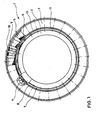
- a yarn storage device 1 consists of a storage drum 2, which is surrounded by a ring 3.
- the storage drum 2 is angularly fixed relative to the ring 3 by a permanent magnet arrangement, not shown.
- a temporary yarn supply can be applied to the storage drum 2 by means of a winding device (not shown), with which an intermittent yarn take-up of a subsequent device using the yarn, such as a loom or a knitting machine, can be compensated.
- the number of yarn turns drawn off from the storage drum 2 is determined by an optoelectronic detection device 4, which consists of a light-emitting diode and a photo transistor.
- the yarn 7 is pulled from the storage drum 2 through a gap 8, which lies between the storage drum 2 and the ring 3.
- a plurality of yarn stopping devices 5, 6 are evenly spaced from one another in the circumferential direction of the storage drum or the ring.
- Each yarn stop device 5, 6 consists of an electromagnet 5 which can be actuated by an electrical control signal and of an actuating element 6 which is located beyond the gap 8 with respect to the electromagnet 5.
- Each electromagnet 5 consists of a coil 9 with a centrally arranged core 10, which lies in the radial direction in the ring 3.
- the storage drum 2 has in the area of its casing 11 a recess 12 in the circumferential direction of the storage drum 2 in the form of an annular groove.
- This annular groove 12 is a belt 13, which consists of neoprene.
- the actuating elements 6 are glued onto the belt 13 at regular intervals, which correspond to the mutual angular distances of the electromagnets 5.
- the actuators are made of a soft magnetic material, preferably iron.
- the actuators are frustoconical.
- other shapes are conceivable instead of the truncated cone shape of the actuating element 6, but it is advantageous if the side of the actuating element, which in its actuated state faces the yarn 7, is inclined relative to the radial direction in such a way that a tension in yarn 7 leads to a reaction force directed inwards in the radial direction of the storage drum 2.
- FIG. 2 An enlarged detail view of a section of the yarn storage device shown in Figure 1 is shown in Figure 2. Those parts which correspond to the parts already described with reference to FIG. 1 are provided with the same reference symbols.
- a part of the yarn stop devices 5 is in the non-actuated state. These yarn stopping devices are designated by the reference symbol 5b.
- a yarn stopping device which is in its actuated state is highlighted by reference number 5a.
- the actuation of the yarn stop device 5a by supplying a control current to its electromagnet leads to a magnetic field which extends along the core 10 and which pulls the actuating element 6 opposite the core 10 into the annular gap 8, so that this rests on the steel strip 14 which the surface of the ring 3 opposite the storage drum 2 is lined.
- the spiral withdrawal of the yarn 7 is interrupted by the storage drum.
- the belt 13 is lifted and stretched from the storage drum 2 in the area of the annular groove 12 and thus acts as a pretensioned return spring for the actuating element 6.
- the total length of the elastic belt 13 is preferably selected to be slightly shorter than the circumference of the annular groove 12 of the storage drum 2. This results in a desired pretensioning of the return device formed by the belt 13 for the actuating element 6 even in the unactuated position of the yarn stoppers 5, 6.
- Figures 3 and 4 represent longitudinal sectional views along the planes 111-111 and IV-IV according to Figure 2.
- the ring 3 has a cavity in which the electromagnet 5 is fixed. So that the magnetic field generated by the coil 9 of the electromagnet 5 is not short-circuited, the ring 3 consists of non-magnetic material, such as a hard plastic. Likewise, the storage drum 2 is made of non-magnetic material. Preferably a magne table path is provided which extends from the outer end of the core 10 in the radial direction into an area of the storage drum 2 which ends directly below the recess 12. In this way, a particularly strong magnetic field can be generated in the area of the actuating element 6.
- the recess or annular groove 12 merges into the casing 11 of the storage drum 2 with annular beads 15 which protrude in the radial direction of the storage drum 2 beyond the casing 11 thereof. Likewise, the annular beads 15 extend inwards relative to the annular groove 12. In this way, a precise guidance of the yarn 7 as it passes through the gap 8 between the ring 3 and the storage drum 2 in the area of the actuating element 6 is ensured.
- the bottom of the annular groove 12 can be corrugated in order to allow the elastic belt 13 to be easily detached when a yarn stop device 5 is activated.
- the actuating elements can engage with the belt by positive locking instead of being glued to it.
- any elastic-resilient material can be used as the material for the belt.
- the belt does not necessarily have to be designed as a closed belt ring, but can also consist of sections which only extend over sections of the circumference of the storage drum.
Landscapes
- Engineering & Computer Science (AREA)
- Textile Engineering (AREA)
- Forwarding And Storing Of Filamentary Material (AREA)
- Looms (AREA)
- Knitting Machines (AREA)
Description
- Die vorliegende Erfindung betrifft ein Gerät zum Speichern von Garn nach dem Oberbegriff des Anspruchs 1.
- Geräte zum Speichern von Garn, die auch als Fournisseure bezeichnet werden, sind allgemein bekannt. Bezüglich der grundsätzlichen Bauweise und Funktionsweise derartiger Geräte wird auf die vorveröffentlichte europäische Patentanmeldung 83 109 818.1 der Anmelderin hingewiesen. Auf den Inhalt dieser europäischen Patentanmeldung wird einerseits als Stand der Technik und andererseits zur Ergänzung der Offenbarung der vorliegenden Erfindung Bezug genommen, um eine Beschreibung allgemein bekannter Maßnahmen auf dem Gebiet der Garnspeichergeräte entbehrlich zu machen.
- Das bekannte Garnspeichergerät weist Betätigungselemente auf, die in Bohrungen im Umfangsbereich der Speichertrommel gelagert sind. Die Garnstopgeräte des bekannten Garnspeichergeräts sind als in dem Ring des Garnspeichergeräts angeordnete Elektromagnete ausgebildet, bei deren Betätigung das jeweils zugeordnete Betätigungselement aus der Bohrung im Umfangsbereich der Speichertrommel herausgezogen wird und in den Spalt zwischen Ring und Speichertrommel gezogen wird, durch den das Garn beim Abzug des Garnes von der Speichertrommel spiralenförmig läuft. In dem Moment, in dem das Betätigungselement so weit in den Spalt hereingezogen ist, daß es am Ring anliegt, versperrt es den Abzugsweg für das Garn von der Speichertrommel, so daß durch Aktivierung des Garnstopgerätes ein weiteres Abziehen von Garn von der Speichertrommel unterbrochen werden kann. Die Rückholvorrichtung für das Betätigungselement des bekannten Garnspeichergerätes wird durch einen Dauermagneten gebildet, der in der Speichertrommel am Ende der Bohrung für die Führung des Betätigungselementes liegt. Obwohl sich das bekannte Garnspeichergerät bei vielfachem Einsatz in der Praxis hervorragend bewährt hat, kam es in einigen Ausnahmefällen nach sehr langen Betriebszeiten des Garnspeichergerätes insbesondere in unsauberer Umgebung zu Störungen in der Bewegung des Betätigungselementes, wobei teilweise ein Rückkehren des Betätigungselementes in die Bohrung oder ein Herausziehen des Betätigungselementes aus der Bohrung durch Schmutzpartikel erschwert oder gänzlich verhindert worden ist.
- Gegenüber diesem Stand der Technik liegt der vorliegenden Erfindung die Aufgabe zugrunde, ein derartiges Gerät zum Speichern von Garn so weiterzubilden, daß dessen Betriebssicherheit auch unter ungünstigen Umgebungsbedingungen weiter verbessert wird.
- Diese Aufgabe wird bei einem Gerät nach dem Oberbegriff des Anspruchs 1 durch die im kennzeichnenden Teil des Anspruchs 1 angegebene Maßnahme gelöst.
- Die erfindungsgemäße Rückholvorrichtung, die durch einen in Umfangsrichtung der Speichertrommel verlaufenden, aus einem elastischen Material bestehenden Riemen gebildet wird, der wenigstens einem Betätigungselement in Eingriff steht, liegt im unbetätigten Zustand der jeweiligen Garnstopgeräte an der Speichertrommel an. Schmutzpartikel können sich daher lediglich auf der in der radialen Richtung der Speichertrommel außenliegenden Seite des Riemens ablagern, wo jedoch eine Verschmutzung nicht zu einer Beeinträchtigung der Betriebssicherheit der Betätigungselemente führen kann. Vorzugsweise sind die Betätigungselemente auf dem Riemen befestigt. Dieser Ausgestaltung des erfindungsgemäßen Gerätes zum Speichern des Garnes hat den Vorteil, daß Führungen für die Betätigungselemente, wie sie bei Garnspeichergeräten nach dem Stand der Technik notwendig sind, entbehrlich werden.
- Vorzugsweise ist der Riemen aus Gummi, insbesondere aus Neopren gefertigt.
- Wenn der Riemen in einer in Umfangsrichtung der Speichertrommel verlaufenden Ausnehmung angeordnet wird, gleitet das Garn beim Abziehen des Garnes von der Speichertrommel alleine über die Mantelfläche der Speichertrommel und wird in seiner Bewegung durch den Riemen im nicht-betätigten Zustand der Garnstopgeräte nicht beeinträchtigt.
- In Umfangsrichtung verlaufende Wülste zwischen der Ausnehmung und dem Mantel der Speichertrommel, die in radialer Richtung der Speichertrommel über den Mantel hinausragen, bilden eine Gleitführungsfläche für das abzuziehende Garn, wodurch ein präzises Anhalten des Garnabzuges von der Speichertrommel bei Betätigung des Garnstopgerätes gewährleistet wird.
- Eine besonders einfache Halterung der Betätigungselemente wird dadurch erreicht, daß diese auf dem Riemen aufgeklebt sind.
- Vorzugsweise sind die Elektromagnete, die zusammen mit den Betätigungselementen die Garnstopgeräte bilden, in dem Ring angeordnet, der die Speichertrommel umgibt. Der Ring ist an seiner den Betätigungselementen gegenüber liegenden Fläche mit einem harten, nicht magnetischen Band, vorzugsweise einem Stahlband ausgekleidet, durch das einerseits eine äußersts ebene, auch gegen langen Betrieb widerstehende Anschlagfläche für die Betätigungselemente gebildet wird. Ferner wird durch das harte, nicht magnetische Band ein magnetisches Ankleben der Betätigungselemente an den Elektromagneten im nicht-betätigten Zustand der Garnstopgeräte erreicht.
- Wenn der Riemen mit Vertiefungen zum Aufnehmen der Betätigungselemente versehen ist, lassen sich diese einerseits besonders sicher mit einem elastischen Klebstoff mit dem Riemen verbinden. Andererseits wird die Fertigung des mit den Betätigungselementen versehenen Riemens dadurch erleichtert, daß der Riemen auch durch eine unerfahrene Fertigungskraft nur an den vorgesehenen Stellen, die gegenüber den Elektromagneten zu liegen kommen, mit den Betätigungselementen versehen wird.
- Vorzugsweise ist der Riemen zu seinen Seiten oder zu der Speichertrommel hin mit Vorsprüngen versehen, die mit Rücksprüngen in der Speichertrommel im Bereich der Ausnehmung Eingriff nehmen, um die winkelmäßige Lage bzw. die Lage in Umfangsrichtung des Riemens bezüglich der Speichertrommel festzulegen. Durch diese Ausgestaltung wird verhindert, daß im Laufe des Betriebes der Riemen auf der Speichertrommel in Umfangsrichtung wandert, wodurch ein sicheres Ansprechen der Betätigungselemente auf die von den Elektromagneten erzeugten Magnetfelder in Frage gestellt sein könnte.
- Nachfolgene wird unter Bezugnahme auf die beiliegenden Zeichnungen eine bevorzugte Ausführungsform des erfindungsgemäßen Gerätes zum Speichern von Garn näher erläutert. Es zeigen:
- Figur 1 eine schematische Darstellung der Querschnittsdarstellung eines Abzugsendes einer Speichertrommel eines Garnspeichergerätes gemäß der vorliegenden Erfindung;
- Figur 2 eine vergrößerte Detaildarstellung des in Figur 1 gezeigten Garnspeichergerätes;
- Figur 3 eine Querschnittsdarstellung durch einen Teil des Garnspeichergerätes im Bereich eines Garnstopgerätes, das sich in seinem nicht-betätigten Zustand befindet;
- Figur 4 eine weitere Querschnittsdarstellung entsprechend Figur 3, bei der das Garnstopgerät in seinem betätigten Zustand gezeigt ist.
- Wie in Figur 1 gezeigt ist, besteht ein Garnspeichergerät 1 aus einer Speichertrommel 2, die von einem Ring 3 umgeben ist.
- Die Speichertrommel 2 wird gegenüber dem Ring 3 durch eine nicht gezeigte Permanentmangnetanordnung winkelmäßig festgelegt. Auf die Speichertrommel 2 kann mittels eines (nicht dargestellten) Aufwickelgerätes ein zeitweiliger Garnvorrat aufgebracht werden, mit der eine intermittierende Garnaufnahme eines nachfolgenden, das Garn verbrauchenden Gerätes, wie beispielsweise eines Webstuhles oder einer Strickmaschine, ausgeglichen werden kann. Die Anzahl der von der Speichertrommel 2 abgezogenen Garnwindungen wird von einer optoelektronischen Erfassungseinrichtung 4, die aus einer Leuchtdiode und einem Fototransistor besteht, ermittelt. Das Garn 7 wird beim Abziehen von der Speichertrommel 2 durch einen Spalt 8 gezogen, der zwischen der Speichertrommel 2 und dem Ring 3 liegt. Eine Mehrzahl von Garnstopgeräten 5, 6 ist in Umfangsrichtung der Speichertrommel bzw. des Ringes gleichmäßig von einander beanstandet angeordnet. Jedes Garnstopgerät 5, 6 besteht aus einem durch ein elektrisches Steuersignal betätigbaren Elektromagneten 5 und aus einem Betätigungselement 6, das bezüglich des Elektromagneten 5 jenseits des Spaltes 8 liegt. Jeder Elektromagnet 5 besteht aus einer Spule 9 mit einem mittig angeordneten Kern 10, der in radialer Richtung im Ring 3 liegt. Die Speichertrommel 2 weist im Bereich ihres Mantels 11 eine in Umfangsrichtung der Speichertrommel 2 verlaufende Ausnehmung 12 in Form einer Ringnut auf. In dieser Ringnut 12 liegt ein Riemen 13, der aus Neopren besteht. Auf dem Riemen 13 sind in regelmäßigen Abständen, die den gegenseitigen Winkelabständen der Elektromagnete 5 entsprechen, die Betätigungselemente 6 aufgeklebt.
- Die Betätigungselemente bestehen aus einem weichmagnetischen Material, vorzugsweise Eisen. Die Betätigungselemente sind kegelstumpfförmig ausgebildet. Jedoch sind auch andere Formen anstelle der Kegelstumpfform des Betätigungselementes 6 denkbar, wobei es jedoch vorteilhaft ist, wenn die Seite des Betätigungselementes, die in dessen betätigten Zustand dem Garn 7 zugewandt ist, derart gegenüber der radialen Richtung geneigt ist, daß eine Spannung in Garn 7 zu einer in radialer Richtung der Speichertrommel 2 nach innen gerichteten Reaktionskraft führt.
- Eine vergrößerte Detaildarstellungeines Ausschnittes des in Figur 1 dargestellten Garnspeichergerätes ist in Figur 2 wiedergegeben. Diejenigen Teile, die den unter Bezugnahme auf Figur 1 bereits beschriebenen Teilen entsprechen, sind mit gleichen Bezugszeichen versehen. Ein Teil der Garnstopgeräte 5 befindet sich in dem nicht-betätigten Zustand. Diese Garnstopgeräte sind mit dem Bezugszeichen 5b bezeichnet. Ein Garnstopgerät, das sich in seinem betätigten Zustand befindet, ist durch das Bezugszeichen 5a hervorgehoben. Die Betätigung des Garnstopgerätes 5a durch Zuführen eines Steuerstromes zu dessen Elektromagneten führt zu einem magnetischen Feld, das sich längs des Kernes 10 erstreckt und das dem Kern 10 gegenüber liegende Betätigungselement 6 in den Ringspalt 8 zieht, so daß dies an dem Stahlband 14 anliegt, mit dem die der Speichertrommel 2 gegenüber liegende Fläche des Ringes 3 ausgekleidet ist. Hierbei wird der spiralenförmige Abzug des Garnes 7 von der Speichertrommel unterbrochen.
- Im Bereich des betätigten Garnstopgerätes oder Elektromagneten 5a wird der Riemen 13 von der Speichertrommel 2 im Bereich der Ringnut 12 abgehoben und gedehnt und wirkt somit als vorgespannte Rückholfeder für das Betätigungselement 6.
- Vorzugsweise ist die Gesamtlänge des elastischen Riemen 13 geringfügig kürzer gewählt als der Umfang der Ringnut 12 der Speichertrommel 2. Hierdurch ergibt sich eine gewünschte Vorspannung der durch den Riemen 13 gebildeten Rückholvorrichtung für das Betätigungselement 6 auch in der unbetätigten Lage der Garnstopgeräte 5,6.
- Die Figuren 3 und 4 stellen Längsschnittdarstellungen längs der Ebenen 111-111 bzw. IV-IV gemäß Figur 2 dar.
- Der Ring 3 weist einen Hohlraum auf, in dem der Elektromagnet 5 festgelegt ist. Damit das durch die Spule 9 des Elektromagneten 5 erzeugte Magnetfeld nicht kurzgeschlossen wird, besteht der Ring 3 aus nicht magnetischem Material, wie beispeilsweise einem Hartkunststoff. Ebenso ist die Speichertrommel 2 aus nicht magnetischem Material gebildet. Vorzugsweise ist ein magnetischer Pfad vorgesehen, der sich von dem in radialer Richtung äußeren Ende des Kernes 10 bis in einen Bereich der Speichertrommel 2 ersteckt, der direkt unterhalb der Ausnehmung 12 endet. Auf diese Weise kann ein besonders starkes Magnetfeld im Bereich des Betätigungselementes 6 erzeugt werden.
- Die Ausnehmung oder Ringnut 12 geht in den Mantel 11 der Speichertrommel 2 mit Ringwülsten 15 über, die in radialer Richtung der Speichertrommel 2 über deren Mantel 11 hinausragen. Gleichfalls erstrecken sich die Ringwülste 15 gegenüber der Ringnut 12 nach innen. Auf diese Weise wird eine präzise Führung des Garnes 7 bei seinem Durchlauf durch den Spalt 8 zwischen dem Ring 3 und der Speichertrommel 2 im Bereich des Betätigunselementes 6 gewährleistet.
- Der Boden der Ringnut 12 kann geriffelt ausgeführt sein, um ein leichtes Ablösen des elastischen Riemens 13 bei Aktivierung eines Garnstopgerätes 5 zu ermöglichen.
- In Abweichung von dem beschreibenen Ausführungsbeispiel können die Betätigungselemente durch Formschluß mit dem Riemen Eingriff nehmen, anstatt mit diesem verklebt zu sein.
- Als Material für den Riemen kommt neben Neopren oder Gummi jeglicher elastisch-federnder Werkstoff in Betracht.
- Der Riemen muß nicht zwangsweise als geschlossener Riemenring ausgeführt sein, sondern kann auch aus Teilstücken bestehen, die sich nur über Teilstrecken des Umfanges der Speichertrommel erstrecken.
Claims (9)
Applications Claiming Priority (2)
| Application Number | Priority Date | Filing Date | Title |
|---|---|---|---|
| DE3628485 | 1986-08-22 | ||
| DE19863628485 DE3628485A1 (de) | 1986-08-22 | 1986-08-22 | Geraet zum speichern von garn |
Publications (2)
| Publication Number | Publication Date |
|---|---|
| EP0278966A1 EP0278966A1 (de) | 1988-08-24 |
| EP0278966B1 true EP0278966B1 (de) | 1990-10-31 |
Family
ID=6307923
Family Applications (1)
| Application Number | Title | Priority Date | Filing Date |
|---|---|---|---|
| EP87905609A Expired - Lifetime EP0278966B1 (de) | 1986-08-22 | 1987-08-19 | Gerät zum speichern von garn |
Country Status (7)
| Country | Link |
|---|---|
| US (1) | US4919173A (de) |
| EP (1) | EP0278966B1 (de) |
| JP (1) | JP2568237B2 (de) |
| KR (1) | KR910000449B1 (de) |
| CS (1) | CS264296B2 (de) |
| DE (2) | DE3628485A1 (de) |
| WO (1) | WO1988001315A1 (de) |
Families Citing this family (5)
| Publication number | Priority date | Publication date | Assignee | Title |
|---|---|---|---|---|
| EP0344100B1 (de) * | 1988-05-20 | 1992-07-08 | GebràDer Sulzer Aktiengesellschaft | Elektromagnetische Einrichtung für Webmaschinen |
| JPH01321951A (ja) * | 1988-06-03 | 1989-12-27 | Gebr Sulzer Ag | 緯糸蓄積装置 |
| CA2020958C (en) * | 1989-07-11 | 2005-01-11 | Daniel L. Kacian | Nucleic acid sequence amplification methods |
| ES2110458T3 (es) * | 1991-09-20 | 1998-02-16 | Lgl Electronics Spa | Dispositivo autoajustable para frenar el hilo en las unidades alimentadoras de trama. |
| NL9402159A (nl) * | 1994-12-20 | 1996-08-01 | Te Strake Bv | Inrichting voor het sturen van een garenloop en vrijgavemiddelen voor toepassing in de inrichting. |
Family Cites Families (12)
| Publication number | Priority date | Publication date | Assignee | Title |
|---|---|---|---|---|
| DE2126845C3 (de) * | 1970-06-01 | 1981-12-24 | Aktiebolaget Iro, Ulricehamn | Fadenspeicher- und -liefervorrichtung |
| US4627474A (en) * | 1982-09-03 | 1986-12-09 | Aktiebolaget Iro | Yarn storing, feeding and measuring device |
| DE3382053D1 (de) * | 1982-09-30 | 1991-01-17 | Iro Ab | Garnspeicher- und zufuehrvorrichtung. |
| JPS59106543A (ja) * | 1982-12-13 | 1984-06-20 | 日産自動車株式会社 | 断片織機の緯糸供給装置 |
| JPS59125944A (ja) * | 1982-12-27 | 1984-07-20 | 日産自動車株式会社 | 断片織機の緯糸供給装置 |
| JPS60155755A (ja) * | 1984-01-20 | 1985-08-15 | 多川機械株式会社 | 回転ドラム式緯糸貯留装置 |
| DE3434257A1 (de) * | 1984-08-16 | 1986-02-27 | Aktiebolaget Iro, Ulricehamn | Fadenspeicher- und -liefervorrichtung |
| US4784191A (en) * | 1984-12-22 | 1988-11-15 | Kabushiki Kaisha Toyoda Jidoshokki Seisakusho | Device for storing a weft yarn for inserting in a jet loom |
| JPS62118053A (ja) * | 1985-11-18 | 1987-05-29 | Sanshin Ind Co Ltd | 船外機の燃料供給装置 |
| CH670263A5 (de) * | 1986-05-23 | 1989-05-31 | Sulzer Ag | |
| JPH01113858A (ja) * | 1987-10-28 | 1989-05-02 | Matsushita Electric Ind Co Ltd | 日本語処理装置 |
| JP2636430B2 (ja) * | 1988-11-01 | 1997-07-30 | アドバンス・コージェネレーションシステム技術研究組合 | 永久磁石付き回転子及びその製造方法 |
-
1986
- 1986-08-22 DE DE19863628485 patent/DE3628485A1/de not_active Withdrawn
-
1987
- 1987-08-17 CS CS876037A patent/CS264296B2/cs unknown
- 1987-08-19 US US07/192,510 patent/US4919173A/en not_active Expired - Fee Related
- 1987-08-19 DE DE8787905609T patent/DE3765931D1/de not_active Expired - Lifetime
- 1987-08-19 WO PCT/EP1987/000467 patent/WO1988001315A1/de not_active Ceased
- 1987-08-19 EP EP87905609A patent/EP0278966B1/de not_active Expired - Lifetime
- 1987-08-19 KR KR1019880700170A patent/KR910000449B1/ko not_active Expired
- 1987-08-19 JP JP62505141A patent/JP2568237B2/ja not_active Expired - Lifetime
Also Published As
| Publication number | Publication date |
|---|---|
| DE3628485A1 (de) | 1988-02-25 |
| JPH01501012A (ja) | 1989-04-06 |
| US4919173A (en) | 1990-04-24 |
| DE3765931D1 (de) | 1990-12-06 |
| WO1988001315A1 (fr) | 1988-02-25 |
| JP2568237B2 (ja) | 1996-12-25 |
| EP0278966A1 (de) | 1988-08-24 |
| CS603787A2 (en) | 1988-06-15 |
| KR880701680A (ko) | 1988-11-04 |
| KR910000449B1 (ko) | 1991-01-25 |
| CS264296B2 (en) | 1989-06-13 |
Similar Documents
| Publication | Publication Date | Title |
|---|---|---|
| EP0201794B1 (de) | Aus zwei Hülsenteilen bestehender Wickelträger | |
| DE68912056T2 (de) | Elektromagnetische Einheit zum Blockieren des Schussfadens in einer Schussfadenmess- und liefervorrichtung für Düsenwebmaschinen. | |
| CH632220A5 (de) | Spulenkoerper fuer garne, faeden und bandfoermiges wicklungsmaterial. | |
| DE2755887C2 (de) | Elektromagnetisch betätigbare Reibungskupplung | |
| EP0045428A1 (de) | Aussenhaken- und Fangspule zum rotativen An- und Aufwickeln | |
| DE69131493T2 (de) | Umlaufender Greifer | |
| WO1988001315A1 (fr) | Dispositif de stockage de fil | |
| DE2848587C2 (de) | Auslösevorrichtung für die selbsttätige Schnellbremsung bewegter Maschinenteile, insbesondere von Webmaschinen | |
| CH681802A5 (de) | ||
| DE69018228T2 (de) | Schussfadenzubringer für Düsenwebmaschinen. | |
| DE2509917A1 (de) | Elektromagnet | |
| DE3001069C2 (de) | ||
| DE890716C (de) | Einrichtung zur selbsttätigen Befestigung von Magnetogrammträgern und Filmen in den Aufwickelspulen | |
| DE3247210C2 (de) | Schalter | |
| DE1535099A1 (de) | Vorrichtung zur Abtastung einer Spulenkoerperoberflaeche | |
| DE4033590A1 (de) | Vorrichtung zum auftragen eines klebstoff-, farb- oder korrekturfilms | |
| EP0083926A2 (de) | Bandkassette mit verschiebbarer Spulenträgerplatte | |
| DE2522875A1 (de) | Sicherheitsgurt-aufrolleinrichtung fuer kraftfahrzeuge | |
| DE4117704C2 (de) | Abreißvorrichtung zum Abreißen von Garnen oder Zwirnen an einer Spinn- oder Zwirnmaschine | |
| DE8520923U1 (de) | Kabelaufwickelvorrichtung | |
| DE8715906U1 (de) | Fadenfangring | |
| WO1990004057A1 (de) | Fadenspeicher- und -liefervorrichtung | |
| DE29518090U1 (de) | Fadenspeicher- und -liefervorrichtung | |
| DE2050040B2 (de) | Aufsteckvorrichtung für Spulen | |
| DE2418628C3 (de) | Schleppflügel für den Überkopfabzug von Fäden |
Legal Events
| Date | Code | Title | Description |
|---|---|---|---|
| PUAI | Public reference made under article 153(3) epc to a published international application that has entered the european phase |
Free format text: ORIGINAL CODE: 0009012 |
|
| 17P | Request for examination filed |
Effective date: 19880127 |
|
| AK | Designated contracting states |
Kind code of ref document: A1 Designated state(s): BE CH DE FR GB IT LI SE |
|
| 17Q | First examination report despatched |
Effective date: 19891128 |
|
| GRAA | (expected) grant |
Free format text: ORIGINAL CODE: 0009210 |
|
| AK | Designated contracting states |
Kind code of ref document: B1 Designated state(s): BE CH DE FR GB IT LI SE |
|
| PG25 | Lapsed in a contracting state [announced via postgrant information from national office to epo] |
Ref country code: GB Effective date: 19901031 Ref country code: FR Effective date: 19901031 |
|
| REF | Corresponds to: |
Ref document number: 3765931 Country of ref document: DE Date of ref document: 19901206 |
|
| ITF | It: translation for a ep patent filed | ||
| EN | Fr: translation not filed | ||
| GBV | Gb: ep patent (uk) treated as always having been void in accordance with gb section 77(7)/1977 [no translation filed] | ||
| ITTA | It: last paid annual fee | ||
| PLBE | No opposition filed within time limit |
Free format text: ORIGINAL CODE: 0009261 |
|
| STAA | Information on the status of an ep patent application or granted ep patent |
Free format text: STATUS: NO OPPOSITION FILED WITHIN TIME LIMIT |
|
| 26N | No opposition filed | ||
| PGFP | Annual fee paid to national office [announced via postgrant information from national office to epo] |
Ref country code: BE Payment date: 19920730 Year of fee payment: 6 |
|
| PGFP | Annual fee paid to national office [announced via postgrant information from national office to epo] |
Ref country code: SE Payment date: 19920731 Year of fee payment: 6 |
|
| PGFP | Annual fee paid to national office [announced via postgrant information from national office to epo] |
Ref country code: CH Payment date: 19920929 Year of fee payment: 6 |
|
| PGFP | Annual fee paid to national office [announced via postgrant information from national office to epo] |
Ref country code: DE Payment date: 19920930 Year of fee payment: 6 |
|
| PG25 | Lapsed in a contracting state [announced via postgrant information from national office to epo] |
Ref country code: SE Effective date: 19930820 |
|
| PG25 | Lapsed in a contracting state [announced via postgrant information from national office to epo] |
Ref country code: LI Effective date: 19930831 Ref country code: CH Effective date: 19930831 Ref country code: BE Effective date: 19930831 |
|
| BERE | Be: lapsed |
Owner name: IRO A.B. Effective date: 19930831 |
|
| REG | Reference to a national code |
Ref country code: CH Ref legal event code: PL |
|
| PG25 | Lapsed in a contracting state [announced via postgrant information from national office to epo] |
Ref country code: DE Effective date: 19940503 |
|
| EUG | Se: european patent has lapsed |
Ref document number: 87905609.1 Effective date: 19940310 |
|
| PG25 | Lapsed in a contracting state [announced via postgrant information from national office to epo] |
Ref country code: IT Free format text: LAPSE BECAUSE OF NON-PAYMENT OF DUE FEES;WARNING: LAPSES OF ITALIAN PATENTS WITH EFFECTIVE DATE BEFORE 2007 MAY HAVE OCCURRED AT ANY TIME BEFORE 2007. THE CORRECT EFFECTIVE DATE MAY BE DIFFERENT FROM THE ONE RECORDED. Effective date: 20050819 |