WO2021176948A1 - ガスバリア積層体及び包装袋 - Google Patents
ガスバリア積層体及び包装袋 Download PDFInfo
- Publication number
- WO2021176948A1 WO2021176948A1 PCT/JP2021/004153 JP2021004153W WO2021176948A1 WO 2021176948 A1 WO2021176948 A1 WO 2021176948A1 JP 2021004153 W JP2021004153 W JP 2021004153W WO 2021176948 A1 WO2021176948 A1 WO 2021176948A1
- Authority
- WO
- WIPO (PCT)
- Prior art keywords
- layer
- gas barrier
- barrier laminate
- base material
- resin
- Prior art date
- Legal status (The legal status is an assumption and is not a legal conclusion. Google has not performed a legal analysis and makes no representation as to the accuracy of the status listed.)
- Ceased
Links
Images




Classifications
-
- B—PERFORMING OPERATIONS; TRANSPORTING
- B32—LAYERED PRODUCTS
- B32B—LAYERED PRODUCTS, i.e. PRODUCTS BUILT-UP OF STRATA OF FLAT OR NON-FLAT, e.g. CELLULAR OR HONEYCOMB, FORM
- B32B27/00—Layered products comprising a layer of synthetic resin
- B32B27/32—Layered products comprising a layer of synthetic resin comprising polyolefins
-
- B—PERFORMING OPERATIONS; TRANSPORTING
- B32—LAYERED PRODUCTS
- B32B—LAYERED PRODUCTS, i.e. PRODUCTS BUILT-UP OF STRATA OF FLAT OR NON-FLAT, e.g. CELLULAR OR HONEYCOMB, FORM
- B32B27/00—Layered products comprising a layer of synthetic resin
- B32B27/06—Layered products comprising a layer of synthetic resin as the main or only constituent of a layer, which is next to another layer of the same or of a different material
- B32B27/08—Layered products comprising a layer of synthetic resin as the main or only constituent of a layer, which is next to another layer of the same or of a different material of synthetic resin
-
- B—PERFORMING OPERATIONS; TRANSPORTING
- B32—LAYERED PRODUCTS
- B32B—LAYERED PRODUCTS, i.e. PRODUCTS BUILT-UP OF STRATA OF FLAT OR NON-FLAT, e.g. CELLULAR OR HONEYCOMB, FORM
- B32B21/00—Layered products comprising a layer of wood, e.g. wood board, veneer, wood particle board
-
- B—PERFORMING OPERATIONS; TRANSPORTING
- B32—LAYERED PRODUCTS
- B32B—LAYERED PRODUCTS, i.e. PRODUCTS BUILT-UP OF STRATA OF FLAT OR NON-FLAT, e.g. CELLULAR OR HONEYCOMB, FORM
- B32B27/00—Layered products comprising a layer of synthetic resin
- B32B27/28—Layered products comprising a layer of synthetic resin comprising synthetic resins not wholly covered by any one of the sub-groups B32B27/30 - B32B27/42
- B32B27/283—Layered products comprising a layer of synthetic resin comprising synthetic resins not wholly covered by any one of the sub-groups B32B27/30 - B32B27/42 comprising polysiloxanes
-
- B—PERFORMING OPERATIONS; TRANSPORTING
- B32—LAYERED PRODUCTS
- B32B—LAYERED PRODUCTS, i.e. PRODUCTS BUILT-UP OF STRATA OF FLAT OR NON-FLAT, e.g. CELLULAR OR HONEYCOMB, FORM
- B32B27/00—Layered products comprising a layer of synthetic resin
- B32B27/38—Layered products comprising a layer of synthetic resin comprising epoxy resins
-
- B—PERFORMING OPERATIONS; TRANSPORTING
- B32—LAYERED PRODUCTS
- B32B—LAYERED PRODUCTS, i.e. PRODUCTS BUILT-UP OF STRATA OF FLAT OR NON-FLAT, e.g. CELLULAR OR HONEYCOMB, FORM
- B32B7/00—Layered products characterised by the relation between layers; Layered products characterised by the relative orientation of features between layers, or by the relative values of a measurable parameter between layers, i.e. products comprising layers having different physical, chemical or physicochemical properties; Layered products characterised by the interconnection of layers
- B32B7/02—Physical, chemical or physicochemical properties
- B32B7/027—Thermal properties
-
- B—PERFORMING OPERATIONS; TRANSPORTING
- B32—LAYERED PRODUCTS
- B32B—LAYERED PRODUCTS, i.e. PRODUCTS BUILT-UP OF STRATA OF FLAT OR NON-FLAT, e.g. CELLULAR OR HONEYCOMB, FORM
- B32B7/00—Layered products characterised by the relation between layers; Layered products characterised by the relative orientation of features between layers, or by the relative values of a measurable parameter between layers, i.e. products comprising layers having different physical, chemical or physicochemical properties; Layered products characterised by the interconnection of layers
- B32B7/04—Interconnection of layers
- B32B7/10—Interconnection of layers at least one layer having inter-reactive properties
-
- B—PERFORMING OPERATIONS; TRANSPORTING
- B32—LAYERED PRODUCTS
- B32B—LAYERED PRODUCTS, i.e. PRODUCTS BUILT-UP OF STRATA OF FLAT OR NON-FLAT, e.g. CELLULAR OR HONEYCOMB, FORM
- B32B7/00—Layered products characterised by the relation between layers; Layered products characterised by the relative orientation of features between layers, or by the relative values of a measurable parameter between layers, i.e. products comprising layers having different physical, chemical or physicochemical properties; Layered products characterised by the interconnection of layers
- B32B7/04—Interconnection of layers
- B32B7/12—Interconnection of layers using interposed adhesives or interposed materials with bonding properties
-
- B—PERFORMING OPERATIONS; TRANSPORTING
- B32—LAYERED PRODUCTS
- B32B—LAYERED PRODUCTS, i.e. PRODUCTS BUILT-UP OF STRATA OF FLAT OR NON-FLAT, e.g. CELLULAR OR HONEYCOMB, FORM
- B32B9/00—Layered products comprising a layer of a particular substance not covered by groups B32B11/00 - B32B29/00
-
- B—PERFORMING OPERATIONS; TRANSPORTING
- B32—LAYERED PRODUCTS
- B32B—LAYERED PRODUCTS, i.e. PRODUCTS BUILT-UP OF STRATA OF FLAT OR NON-FLAT, e.g. CELLULAR OR HONEYCOMB, FORM
- B32B2250/00—Layers arrangement
- B32B2250/03—3 layers
-
- B—PERFORMING OPERATIONS; TRANSPORTING
- B32—LAYERED PRODUCTS
- B32B—LAYERED PRODUCTS, i.e. PRODUCTS BUILT-UP OF STRATA OF FLAT OR NON-FLAT, e.g. CELLULAR OR HONEYCOMB, FORM
- B32B2250/00—Layers arrangement
- B32B2250/05—5 or more layers
-
- B—PERFORMING OPERATIONS; TRANSPORTING
- B32—LAYERED PRODUCTS
- B32B—LAYERED PRODUCTS, i.e. PRODUCTS BUILT-UP OF STRATA OF FLAT OR NON-FLAT, e.g. CELLULAR OR HONEYCOMB, FORM
- B32B2255/00—Coating on the layer surface
- B32B2255/10—Coating on the layer surface on synthetic resin layer or on natural or synthetic rubber layer
-
- B—PERFORMING OPERATIONS; TRANSPORTING
- B32—LAYERED PRODUCTS
- B32B—LAYERED PRODUCTS, i.e. PRODUCTS BUILT-UP OF STRATA OF FLAT OR NON-FLAT, e.g. CELLULAR OR HONEYCOMB, FORM
- B32B2255/00—Coating on the layer surface
- B32B2255/20—Inorganic coating
-
- B—PERFORMING OPERATIONS; TRANSPORTING
- B32—LAYERED PRODUCTS
- B32B—LAYERED PRODUCTS, i.e. PRODUCTS BUILT-UP OF STRATA OF FLAT OR NON-FLAT, e.g. CELLULAR OR HONEYCOMB, FORM
- B32B2255/00—Coating on the layer surface
- B32B2255/20—Inorganic coating
- B32B2255/205—Metallic coating
-
- B—PERFORMING OPERATIONS; TRANSPORTING
- B32—LAYERED PRODUCTS
- B32B—LAYERED PRODUCTS, i.e. PRODUCTS BUILT-UP OF STRATA OF FLAT OR NON-FLAT, e.g. CELLULAR OR HONEYCOMB, FORM
- B32B2272/00—Resin or rubber layer comprising scrap, waste or recycling material
-
- B—PERFORMING OPERATIONS; TRANSPORTING
- B32—LAYERED PRODUCTS
- B32B—LAYERED PRODUCTS, i.e. PRODUCTS BUILT-UP OF STRATA OF FLAT OR NON-FLAT, e.g. CELLULAR OR HONEYCOMB, FORM
- B32B2307/00—Properties of the layers or laminate
- B32B2307/30—Properties of the layers or laminate having particular thermal properties
-
- B—PERFORMING OPERATIONS; TRANSPORTING
- B32—LAYERED PRODUCTS
- B32B—LAYERED PRODUCTS, i.e. PRODUCTS BUILT-UP OF STRATA OF FLAT OR NON-FLAT, e.g. CELLULAR OR HONEYCOMB, FORM
- B32B2307/00—Properties of the layers or laminate
- B32B2307/30—Properties of the layers or laminate having particular thermal properties
- B32B2307/31—Heat sealable
-
- B—PERFORMING OPERATIONS; TRANSPORTING
- B32—LAYERED PRODUCTS
- B32B—LAYERED PRODUCTS, i.e. PRODUCTS BUILT-UP OF STRATA OF FLAT OR NON-FLAT, e.g. CELLULAR OR HONEYCOMB, FORM
- B32B2307/00—Properties of the layers or laminate
- B32B2307/50—Properties of the layers or laminate having particular mechanical properties
- B32B2307/514—Oriented
-
- B—PERFORMING OPERATIONS; TRANSPORTING
- B32—LAYERED PRODUCTS
- B32B—LAYERED PRODUCTS, i.e. PRODUCTS BUILT-UP OF STRATA OF FLAT OR NON-FLAT, e.g. CELLULAR OR HONEYCOMB, FORM
- B32B2307/00—Properties of the layers or laminate
- B32B2307/50—Properties of the layers or laminate having particular mechanical properties
- B32B2307/544—Torsion strength; Torsion stiffness
-
- B—PERFORMING OPERATIONS; TRANSPORTING
- B32—LAYERED PRODUCTS
- B32B—LAYERED PRODUCTS, i.e. PRODUCTS BUILT-UP OF STRATA OF FLAT OR NON-FLAT, e.g. CELLULAR OR HONEYCOMB, FORM
- B32B2307/00—Properties of the layers or laminate
- B32B2307/70—Other properties
- B32B2307/724—Permeability to gases, adsorption
- B32B2307/7242—Non-permeable
- B32B2307/7244—Oxygen barrier
-
- B—PERFORMING OPERATIONS; TRANSPORTING
- B32—LAYERED PRODUCTS
- B32B—LAYERED PRODUCTS, i.e. PRODUCTS BUILT-UP OF STRATA OF FLAT OR NON-FLAT, e.g. CELLULAR OR HONEYCOMB, FORM
- B32B2307/00—Properties of the layers or laminate
- B32B2307/70—Other properties
- B32B2307/724—Permeability to gases, adsorption
- B32B2307/7242—Non-permeable
- B32B2307/7246—Water vapor barrier
-
- B—PERFORMING OPERATIONS; TRANSPORTING
- B32—LAYERED PRODUCTS
- B32B—LAYERED PRODUCTS, i.e. PRODUCTS BUILT-UP OF STRATA OF FLAT OR NON-FLAT, e.g. CELLULAR OR HONEYCOMB, FORM
- B32B2307/00—Properties of the layers or laminate
- B32B2307/70—Other properties
- B32B2307/732—Dimensional properties
- B32B2307/737—Dimensions, e.g. volume or area
- B32B2307/7375—Linear, e.g. length, distance or width
- B32B2307/7376—Thickness
-
- B—PERFORMING OPERATIONS; TRANSPORTING
- B32—LAYERED PRODUCTS
- B32B—LAYERED PRODUCTS, i.e. PRODUCTS BUILT-UP OF STRATA OF FLAT OR NON-FLAT, e.g. CELLULAR OR HONEYCOMB, FORM
- B32B2307/00—Properties of the layers or laminate
- B32B2307/70—Other properties
- B32B2307/75—Printability
-
- B—PERFORMING OPERATIONS; TRANSPORTING
- B32—LAYERED PRODUCTS
- B32B—LAYERED PRODUCTS, i.e. PRODUCTS BUILT-UP OF STRATA OF FLAT OR NON-FLAT, e.g. CELLULAR OR HONEYCOMB, FORM
- B32B2439/00—Containers; Receptacles
- B32B2439/02—Open containers
- B32B2439/06—Bags, sacks, sachets
-
- B—PERFORMING OPERATIONS; TRANSPORTING
- B65—CONVEYING; PACKING; STORING; HANDLING THIN OR FILAMENTARY MATERIAL
- B65D—CONTAINERS FOR STORAGE OR TRANSPORT OF ARTICLES OR MATERIALS, e.g. BAGS, BARRELS, BOTTLES, BOXES, CANS, CARTONS, CRATES, DRUMS, JARS, TANKS, HOPPERS, FORWARDING CONTAINERS; ACCESSORIES, CLOSURES, OR FITTINGS THEREFOR; PACKAGING ELEMENTS; PACKAGES
- B65D65/00—Wrappers or flexible covers; Packaging materials of special type or form
- B65D65/38—Packaging materials of special type or form
- B65D65/40—Applications of laminates for particular packaging purposes
-
- Y—GENERAL TAGGING OF NEW TECHNOLOGICAL DEVELOPMENTS; GENERAL TAGGING OF CROSS-SECTIONAL TECHNOLOGIES SPANNING OVER SEVERAL SECTIONS OF THE IPC; TECHNICAL SUBJECTS COVERED BY FORMER USPC CROSS-REFERENCE ART COLLECTIONS [XRACs] AND DIGESTS
- Y02—TECHNOLOGIES OR APPLICATIONS FOR MITIGATION OR ADAPTATION AGAINST CLIMATE CHANGE
- Y02W—CLIMATE CHANGE MITIGATION TECHNOLOGIES RELATED TO WASTEWATER TREATMENT OR WASTE MANAGEMENT
- Y02W30/00—Technologies for solid waste management
- Y02W30/50—Reuse, recycling or recovery technologies
- Y02W30/80—Packaging reuse or recycling, e.g. of multilayer packaging
Definitions
- This disclosure relates to gas barrier laminates and packaging bags.
- a laminate having a biaxially stretched PET (polyethylene terephthalate) film having excellent heat resistance and toughness as a base film and a polyolefin film such as polyethylene or polypropylene as a sealant layer is known (see, for example, Patent Document 1). ..
- polyethylene film which is a kind of polyolefin film
- polyethylene film is widely used as a packaging material, and is expected to be made into a monomaterial with polyethylene film.
- the basic physical characteristics of the polyethylene film are that it has a low melting point, and the film is easily stretched and deformed even at a low temperature. Therefore, when an inorganic oxide layer is formed on a polyethylene film by a method such as vapor deposition to impart high gas barrier properties, the inorganic oxide layer on the polyethylene film is easily cracked during or after processing, resulting in high gas barrier properties. There is a problem that it cannot be retained. Further, the inorganic oxide layer provided on the polyethylene film is particularly liable to crack at the time of bending. Therefore, there is a demand for the development of a laminate that can maintain a high gas barrier property even after bending.
- the present disclosure has been made in view of the above circumstances, and an object of the present disclosure is to provide a gas barrier laminate capable of maintaining a high gas barrier property even after bending while mainly composed of a polyolefin-based film.
- the present disclosure is also intended to provide a packaging bag using the gas barrier laminate.
- a base material layer containing polyolefin, an undercoat layer, an inorganic oxide layer, a gas barrier adhesive layer, and a resin layer containing polyolefin are laminated in this order.
- a gas barrier laminate having the above-mentioned structure.
- the thin, hard, and brittle inorganic oxide layer is easily cracked on the soft and stretchable base material layer. , There is a tendency that gas barrier properties cannot be fully exhibited.
- the gas barrier laminate of the present disclosure since the undercoat layer for providing the inorganic oxide layer is provided on the base material layer, the inorganic oxide layer is uniformly formed on the undercoat layer. And it is possible to suppress the occurrence of cracks in the inorganic oxide layer due to the elongation of the base material layer.
- the gas barrier adhesive layer protects the inorganic oxide layer and can be used for a bending test as a packaging material.
- a gas barrier laminate that can withstand can be obtained.
- the layer provided on the inorganic oxide layer is an adhesive layer that does not have a gas barrier property or a barrier layer that does not have a function as an adhesive, a high gas barrier property should be maintained after the bending test. It is difficult.
- the adhesive layer having a gas barrier property on the inorganic oxide layer cracking of the inorganic oxide layer at the time of bending can be suppressed, and a part of the inorganic oxide layer is temporarily cracked.
- the gas barrier adhesive layer can fill the slight cracks and suppress the deterioration of the gas barrier property. Further, in the gas barrier laminate of the present disclosure, since both the base material layer and the resin layer are layers containing polyolefin, it is possible to realize monomaterialization.
- the thickness of the gas barrier adhesive layer may be 50 times or more the thickness of the inorganic oxide layer. Since the gas barrier adhesive layer has not only a role as an adhesive but also a role as a protective coat layer, it can be used with a thickness of 50 times or more that of the inorganic oxide layer. When the gas barrier adhesive layer has the above thickness, cracking of the inorganic oxide layer can be more sufficiently suppressed, and the gas barrier property of the gas barrier laminate can be further improved. Further, when the gas barrier adhesive layer has the above thickness, it is possible to obtain a cushioning property that cushions an impact from the outside, and it is possible to prevent the inorganic oxide layer from being cracked by the impact.
- the oxygen permeability of the gas barrier adhesive layer may be 100 cc / m 2 , day, atm or less.
- the gas barrier property of the gas barrier laminate can be further improved, and the deterioration of the gas barrier property after bending can be further suppressed.
- the oxygen permeability of the gas barrier adhesive layer is within the above range. The decrease in gas barrier property can be further suppressed.
- the logarithmic decrement of the surface of the gas barrier adhesive layer at 30 ° C. measured by a rigid pendulum type physical property tester may be 0.1 or less.
- the logarithmic decrement of the surface of the gas barrier adhesive layer is 0.1 or less, the gas barrier property of the gas barrier laminate can be further improved, and the deterioration of the gas barrier property after bending can be further suppressed. can.
- the logarithmic decrement rate is low, the molecules on the surface of the gas barrier adhesive layer become difficult to move, and gas molecules such as oxygen do not easily pass through, so that it is considered that higher gas barrier properties can be obtained.
- the gas barrier adhesive layer may be a layer formed by using an epoxy adhesive. Since the epoxy resin tends to form a dense film due to its molecular structure, the gas barrier adhesive layer formed by using the epoxy adhesive tends to exhibit higher gas barrier properties. In particular, the gas barrier adhesive layer formed by using an epoxy adhesive and having a logarithmic decrement of 0.1 or less is likely to exhibit even more excellent gas barrier properties.
- the inorganic oxide layer may contain silicon oxide. Since the inorganic oxide layer containing silicon oxide easily suppresses deterioration of the gas barrier property due to stretching or bending, it is easy to suppress deterioration of the gas barrier property of the gas barrier laminate using the base material layer containing polyolefin, which is easily deformed.
- the resin layer may be a sealant layer
- the heat fusion temperature difference between the base material layer and the sealant layer may be 10 ° C. or more.
- the Tg difference between the undercoat layer and the gas barrier adhesive layer may be 100 ° C. or less.
- the inorganic material arranged between the undercoat layer and the gas barrier adhesive layer during heat sealing or processing of the gas barrier laminate. It is possible to prevent the inorganic oxide layer from cracking due to stress applied to the oxide layer.
- the gas barrier laminate may have a structure in which printing layers are further laminated. Further, the gas barrier laminate may have a structure in which the resin layer is used as the first resin layer and a second resin layer containing polyolefin is further laminated in addition to the first resin layer.
- the print layer is usually formed on the surface opposite to the undercoat layer of the base material layer.
- the heat fusion temperature difference between the two most distant layers among the three layers of the base material layer, the first resin layer, and the second resin layer is 10 ° C. That may be the above. This makes it easy to mold the gas barrier laminate into a packaging bag or the like by heat sealing.
- the present disclosure also provides a packaging bag made by making the above-mentioned gas barrier laminate.
- the present disclosure it is possible to provide a gas barrier laminate capable of maintaining high gas barrier properties even after bending even when a polyolefin-based film is mainly used.
- the present disclosure can also provide a packaging bag using the gas barrier laminate.
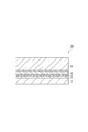
- FIG. 1 is a schematic cross-sectional view showing a gas barrier laminate according to an embodiment.
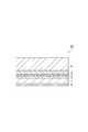
- FIG. 2 is a schematic cross-sectional view showing a gas barrier laminate according to an embodiment.
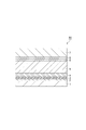
- FIG. 3 is a schematic cross-sectional view showing a gas barrier laminate according to an embodiment.
- FIG. 4 is a schematic cross-sectional view showing a gas barrier laminate according to an embodiment.
- FIG. 5 is a schematic cross-sectional view showing a gas barrier laminate according to an embodiment.
- FIG. 6 is a perspective view showing an embodiment of a packaging bag with a spout.
- FIG. 7 is a front view showing an embodiment of the tube container.
- FIG. 1 is a schematic cross-sectional view showing a gas barrier laminate according to an embodiment.
- the gas barrier laminate 10 shown in FIG. 1 includes a base material layer 1, an undercoat layer 2, an inorganic oxide layer 3, a gas barrier adhesive layer 4, and a resin layer (first resin layer) 5 in this order. Both the base material layer 1 and the first resin layer 5 contain polyolefin.
- FIG. 2 is a schematic cross-sectional view showing a gas barrier laminate according to another embodiment.
- the gas barrier laminate 20 shown in FIG. 2 further includes a print layer 6 on the outside of the base material layer (on the surface opposite to the undercoat layer 2) in the gas barrier laminate 10 shown in FIG.
- FIG. 3 is a schematic cross-sectional view showing a gas barrier laminate according to another embodiment.
- the gas barrier laminate 30 shown in FIG. 3 has a structure in which a printing layer 6 and a second resin layer 7 are laminated on the outside of the base material layer in the gas barrier laminate 10 shown in FIG. 1 via an adhesive layer 8.
- the second resin layer 7 contains polyolefin.
- FIG. 4 is a schematic cross-sectional view showing a gas barrier laminate according to another embodiment.
- the gas barrier laminate 40 shown in FIG. 4 includes a first resin layer 5, a printing layer 6, a gas barrier adhesive layer 4, an inorganic oxide layer 3, an undercoat layer 2, a base material layer 1, an adhesive layer 8, and the like.
- the second resin layer 7 is provided in this order.
- FIG. 5 is a schematic cross-sectional view showing a gas barrier laminate according to another embodiment.
- the gas barrier laminate 50 shown in FIG. 5 has a print layer 6 and an adhesive layer on the outside of the first resin layer 5 (on the surface opposite to the gas barrier adhesive layer 4) in the gas barrier laminate 10 shown in FIG. It has a structure in which 8 and the second resin layer 7 are laminated.
- the first resin layer 5 can be provided with a function as a sealant layer.
- the second resin layer 7 can be provided with a function as a sealant layer.
- the base material layer 1 is a film serving as a support and contains polyolefin.
- the content of the polyolefin in the base material layer 1 may be 50% by mass or more, 80% by mass or more, or 100% by mass based on the total amount of the base material layer 1. It is preferable to use polyolefin as the material of the base material layer 1 from the viewpoint of recyclability. Further, the higher the content of polyolefin in the base material layer 1, the better the recyclability.
- the base material layer 1 may be made of a polyolefin film.
- the polyolefin include polyethylene (PE), polypropylene (PP), polybutene (PB) and the like.
- the polyolefin may be polyethylene.
- the polyolefin include acid-modified polyolefins obtained by graft-modifying a polyolefin with an unsaturated carboxylic acid, an acid anhydride of an unsaturated carboxylic acid, an ester of an unsaturated carboxylic acid, or the like.
- the polyolefin is preferably polypropylene from the viewpoint of retort treatment resistance.
- the polypropylene may be a homopolypropylene or a propylene copolymer.
- a coat layer such as an easy-adhesion layer containing a propylene copolymer may be provided on the laminated surface of the base material layer 1 (the surface on the side where the undercoat layer 2 is laminated).
- the easy-adhesion layer can be provided between the base material layer 1 and the undercoat layer 2.
- the density of the polyolefin contained in the base material layer 1 may be 0.900 g / cm 3 or more, or 0.910 g / cm 3 or more. Also, if the polyolefin contained in the substrate layer 1 is a polyethylene, its density may also be 0.930 g / cm 3 or more, may also be 0.935 g / cm 3 or more, 0.945 g / It may be cm 3 or more. When the density of the polyolefin is 0.935 g / cm 3 or more, it is easy to prevent the base material layer 1 from stretching and wrinkling during roll processing, and it is easy to prevent the inorganic oxide layer 3 from cracking. ..
- the base material layer 1 may contain a biomass-derived or recycled polyolefin.
- the structure of the base material layer 1 may be a multi-layer structure including a plurality of layers (films) containing polyolefins having different densities. It is desirable that the base material layer 1 is appropriately multi-layered in consideration of processability, rigidity, waist strength, heat resistance, powder removal during transportation, and the like of the film constituting the base material layer 1.
- the film constituting the base material layer 1 can be produced by appropriately selecting and using high-density polyolefin, medium-density polyolefin, low-density polyolefin, and the like. When the density of the film is measured as the base material layer 1, the density is preferably 0.900 g / cm 3 or more. Further, the content of the slip agent, antistatic agent, etc.
- the base material layer 1 having a plurality of layers can be laminated and formed into a film by extrusion coating, coextrusion coating, sheet molding, coextrusion blow molding, or the like.
- the total thickness of the base material layer 1 including the plurality of layers is preferably about 10 to 100 ⁇ m, more preferably 15 to 50 ⁇ m.
- the film constituting the base material layer 1 may be a stretched film or a non-stretched film.
- the film constituting the base material layer 1 may be a stretched film.
- the printing layer 6 is provided on the base material layer 1, there is an advantage that the stretched film is easier to print.
- the gas barrier laminate can be more preferably used for the purpose of performing the boil treatment.
- the stretching method is not particularly limited, and any method may be used as long as a film having stable dimensions can be supplied, such as stretching by inflation, uniaxial stretching, or biaxial stretching.
- the base material layer 1 preferably has a heat shrinkage rate of 3% or less in the traveling direction (MD direction) and the vertical direction (TD direction) after being heated at 100 ° C. for 15 minutes, and more preferably 2% or less. It is preferably 1.5% or less, and more preferably 1.5% or less.
- MD direction traveling direction
- TD direction vertical direction
- the heat shrinkage rate of the base material layer 1 is within the above range, it is easy to prevent the base material layer 1 from stretching and wrinkling during roll processing, and it is possible to prevent the inorganic oxide layer 3 from cracking. easy.
- the heat shrinkage rate (%) is a value calculated by the following formula.
- Heat shrinkage rate (%) ⁇ (length before heating-length after heating) / length before heating ⁇ x 100
- the procedure for measuring the heat shrinkage rate is as follows. (1) The base material layer 1 is cut out into a size of 20 cm ⁇ 20 cm and used as a measurement sample. (2) Draw a 10 cm line in the MD direction or TD direction of the measurement sample (length before heating). (3) The measurement sample is heated at 100 ° C. for 15 minutes. (4) Measure the length of the written line in the MD direction or the TD direction (length after heating). (5) The heat shrinkage rate is calculated from the above formula.
- the thickness of the base material layer 1 is not particularly limited. Depending on the application, the thickness can be 6 to 200 ⁇ m, but from the viewpoint of obtaining excellent impact resistance and excellent gas barrier property, it may be 9 to 50 ⁇ m or 12 to 38 ⁇ m.
- the base material layer 1 has a corona treatment, a plasma treatment, a low temperature plasma treatment, and a frame on the laminated surface within a range that does not impair the barrier performance.
- Various pretreatments such as treatment, chemical treatment, solvent treatment, ozone treatment, etc. may be performed, or a coat layer such as an easy-adhesion layer may be provided.
- the base material layer 1 may contain additives such as fillers, antiblocking agents, antistatic agents, plasticizers, lubricants, and antioxidants. Any one of these additives may be used alone, or two or more thereof may be used in combination.
- An undercoat layer (anchor coat layer) 2 is provided on the surface of the base material layer 1 on which the inorganic oxide layer 3 is laminated.
- the undercoat layer 2 has improved adhesion performance between the base material layer 1 and the inorganic oxide layer 3, improved smoothness on the surface of the base material layer 1, and cracking of the inorganic oxide layer 3 due to elongation of the base material layer 1. It can have the effect of suppressing the occurrence of. By improving the smoothness, it becomes easy to form the inorganic oxide layer 3 uniformly without defects, and it is easy to develop a high barrier property.
- the undercoat layer 2 can be formed by using a composition for forming an undercoat layer (anchor coating agent).
- the resin used for the anchor coating agent examples include acrylic resin, epoxy resin, acrylic urethane resin, polyester polyurethane resin, and polyether polyurethane resin.
- the resin used for the anchor coating agent an acrylic urethane resin and a polyester polyurethane resin are preferable from the viewpoint of heat resistance and interlayer adhesion strength.
- the undercoat layer 2 can be formed by using these resins or an anchor coating agent containing a component that reacts to form these resins.
- the thickness of the undercoat layer 2 is not particularly limited, but is preferably in the range of 0.01 to 5 ⁇ m, more preferably in the range of 0.03 to 3 ⁇ m, and preferably in the range of 0.05 to 2 ⁇ m. Is particularly preferable. When the thickness of the undercoat layer 2 is at least the above lower limit value, more sufficient interlayer adhesion strength tends to be obtained, while when it is at least the above upper limit value, the desired gas barrier property tends to be easily exhibited.
- a known coating method can be used without particular limitation, and a dipping method (dipping method); a spray, a coater, a printing machine, a brush, or the like is used.
- the method can be mentioned.
- the types of coaters and printing machines used in these methods and their coating methods include gravure coaters such as direct gravure method, reverse gravure method, kiss reverse gravure method, and offset gravure method, reverse roll coater, and micro gravure. Examples include coaters, chamber doctor combined coaters, air knife coaters, dip coaters, bar coaters, comma coaters, and die coaters.
- the coating amount of the undercoat layer 2 is preferably mass per 1 m 2 after drying by coating an anchor coating agent is 0.01 ⁇ 5g / m 2, 0.03 ⁇ 3g / m 2 Is more preferable. If the mass per 1 m 2 after applying the anchor coating agent and drying is at least the above lower limit, the film formation tends to be sufficient, while if it is at least the above upper limit, it is easy to sufficiently dry and the solvent is released. It tends to be difficult to remain.
- the method for drying the undercoat layer 2 is not particularly limited, but a method by natural drying, a method of drying in an oven set to a predetermined temperature, a dryer attached to the coater, for example, an arch dryer, a floating dryer, a drum, etc. A method using a dryer, an infrared dryer, or the like can be mentioned. Further, the drying conditions can be appropriately selected depending on the drying method. For example, in the method of drying in an oven, it is preferable to dry at a temperature of 60 to 100 ° C. for about 1 second to 2 minutes.
- a polyvinyl alcohol-based resin can be used instead of the above-mentioned resin.
- the polyvinyl alcohol-based resin may have a vinyl alcohol unit obtained by saponifying the vinyl ester unit, and examples thereof include polyvinyl alcohol (PVA) and ethylene-vinyl alcohol copolymer (EVOH).
- the PVA for example, vinyl esters such as vinyl acetate, vinyl formate, vinyl propionate, vinyl valerate, vinyl caprate, vinyl laurate, vinyl stearate, vinyl pivalate, and vinyl versatic acid are independently polymerized. Then, the saponified resin is mentioned.
- the PVA may be a copolymerized or post-modified modified PVA.
- the modified PVA can be obtained, for example, by copolymerizing a vinyl ester with an unsaturated monomer copolymerizable with the vinyl ester and then saponifying the vinyl ester.
- Unsaturated monomers copolymerizable with vinyl esters include, for example, olefins such as ethylene, propylene, isobutylene, ⁇ -octene, ⁇ -dodecene, ⁇ -octadecene; 3-butene-1-ol, 4-pentin-1-ol.
- olefins such as ethylene, propylene, isobutylene, ⁇ -octene, ⁇ -dodecene, ⁇ -octadecene; 3-butene-1-ol, 4-pentin-1-ol.
- the degree of polymerization of PVA is preferably 300 to 3000. When the degree of polymerization is 300 or more, the barrier property is likely to be improved, and when it is 3000 or less, the viscosity is too high and it is easy to prevent the coating suitability from being lowered.
- the degree of saponification of PVA is preferably 90 mol% or more, more preferably 95 mol% or more, still more preferably 99 mol% or more. Further, the degree of saponification of PVA may be 100 mol% or less or 99.9 mol% or less.
- the degree of polymerization and the degree of saponification of PVA can be measured according to the method described in JIS K 6726 (1994).
- EVOH is generally a copolymer of ethylene and an acid vinyl ester such as vinyl acetate, vinyl formate, vinyl propionate, vinyl valerate, vinyl caprate, vinyl laurate, vinyl stearate, vinyl pivalate, vinyl versatic acid and the like. Obtained by converting coalescence into Ken.
- the degree of polymerization of EVOH is preferably 300 to 3000. When the degree of polymerization is 300 or more, the barrier property is likely to be improved, and when it is 3000 or less, the viscosity is too high and it is easy to prevent the coating suitability from being lowered.
- the degree of saponification of the vinyl ester component of EVOH is preferably 90 mol% or more, more preferably 95 mol% or more, still more preferably 99 mol% or more. Further, the degree of saponification of EVOH may be 100 mol% or less or 99.9 mol% or less.
- the degree of saponification of EVOH is determined from the peak area of hydrogen atoms contained in the vinyl ester structure and the peak area of hydrogen atoms contained in the vinyl alcohol structure by performing nuclear magnetic resonance (1 H-NMR) measurement.
- the ethylene unit content of EVOH is 10 mol% or more, more preferably 15 mol% or more, further preferably 20 mol% or more, and particularly preferably 25 mol% or more.
- the ethylene unit content of EVOH is preferably 65 mol% or less, more preferably 55 mol% or less, still more preferably 50 mol% or less.
- the gas barrier property or dimensional stability under high humidity can be kept good.
- the gas barrier property can be enhanced.
- the ethylene unit content of EVOH can be determined by the NMR method.
- examples of the method for forming the undercoat layer 2 include coating with a polyvinyl alcohol-based resin solution, multi-layer extrusion, and the like.
- the constituent material of the inorganic oxide layer 3 examples include inorganic oxides such as aluminum oxide, silicon oxide, magnesium oxide, and tin oxide. From the viewpoint of transparency and barrier property, the inorganic oxide may be selected from the group consisting of aluminum oxide, silicon oxide, and magnesium oxide. Further, from the viewpoint of excellent tensile stretchability during processing, it is preferable that the inorganic oxide layer 3 is a layer using silicon oxide. By using the inorganic oxide layer 3, a high barrier property can be obtained with a very thin layer within a range that does not affect the recyclability of the gas barrier laminate.
- the O / Si ratio of the inorganic oxide layer 3 is 1.7 or more.
- the content ratio of metallic Si is suppressed and good transparency can be easily obtained.
- the O / Si ratio is preferably 2.0 or less.
- the crystallinity of SiO becomes high and the inorganic oxide layer can be prevented from becoming too hard, and good tensile resistance can be obtained. As a result, it is possible to prevent cracks from being generated in the inorganic oxide layer 3 when the gas barrier adhesive layer 4 is laminated.
- the base material layer 1 may shrink due to the heat during the boiling treatment even after molding into the packaging bag, but the O / Si ratio of 2.0 or less makes it easy for the inorganic oxide layer to follow the shrinkage. , It is possible to suppress the decrease in barrier property. From the viewpoint of obtaining these effects more sufficiently, the O / Si ratio of the inorganic oxide layer 3 is preferably 1.75 or more and 1.9 or less, and more preferably 1.8 or more and 1.85 or less. ..
- the O / Si ratio of the inorganic oxide layer 3 can be determined by X-ray photoelectron spectroscopy (XPS).
- XPS X-ray photoelectron spectroscopy
- the measuring device is an X-ray photoelectron spectroscopic analyzer (manufactured by JEOL Ltd., trade name: JPS-90MXV), the X-ray source is non-monochromatic MgK ⁇ (1253.6 eV), and 100 W (10 kV-10 mA). ) Can be measured with the X-ray output.
- a relative sensitivity factor of 2.28 for O1s and 0.9 for Si2p can be used, respectively.
- the film thickness of the inorganic oxide layer 3 is preferably 10 nm or more and 50 nm or less.
- the film thickness is 10 nm or more, sufficient gas barrier properties can be obtained.
- the film thickness is 50 nm or less, it is possible to suppress the occurrence of cracks due to the deformation of the thin film due to the internal stress, and to suppress the deterioration of the gas barrier property.
- the film thickness is 50 nm or less, it is easy to suppress an increase in cost due to an increase in the amount of material used and a long film formation time, which is preferable from an economical point of view.
- the film thickness of the inorganic oxide layer is more preferably 20 nm or more and 40 nm or less.
- the inorganic oxide layer 3 can be formed by, for example, vacuum film formation.
- a physical vapor deposition method or a chemical vapor deposition method can be used.
- the physical vapor deposition method include, but are not limited to, a vacuum deposition method, a sputtering method, and an ion plating method.
- the chemical vapor deposition method include, but are not limited to, a thermal CVD method, a plasma CVD method, and an optical CVD method.
- resistance heating type vacuum deposition method In the above vacuum deposition, resistance heating type vacuum deposition method, EB (Electron Beam) heating type vacuum deposition method, induction heating type vacuum deposition method, sputtering method, reactive sputtering method, dual magnetron sputtering method, plasma chemical vapor deposition method (PECVD method) and the like are particularly preferably used.
- EB Electro Beam
- induction heating type vacuum deposition method sputtering method, reactive sputtering method, dual magnetron sputtering method, plasma chemical vapor deposition method (PECVD method) and the like
- PECVD method plasma chemical vapor deposition method
- the heating means of the vacuum vapor deposition method it is preferable to use any one of an electron beam heating method, a resistance heating method, and an induction heating method.
- the gas barrier adhesive layer 4 has the effect of adhering the inorganic oxide layer 3 and the first resin layer 5 and protecting the inorganic oxide layer 3 to prevent the inorganic oxide layer 3 from cracking during bending.
- the gas barrier adhesive layer 4 is a layer having a gas barrier property. By providing the gas barrier adhesive layer 4, the gas barrier property of the gas barrier laminate can be improved.
- the oxygen permeability of the gas barrier adhesive layer 4 is preferably 150 cc / m 2 ⁇ day ⁇ atm or less, more preferably 100 cc / m 2 ⁇ day ⁇ atm or less, and 80 cc / m 2 ⁇ day ⁇ ⁇ . It is more preferably atm or less, and particularly preferably 50 cc / m 2 ⁇ day ⁇ atm or less.
- the gas barrier property of the gas barrier laminate can be sufficiently improved, and even if the inorganic oxide layer 3 is slightly cracked, the gaps thereof can be filled.
- the gas barrier adhesive layer 4 can enter and complement the gas barrier adhesive layer 4, and can suppress the deterioration of the gas barrier property.
- the gas barrier adhesive layer 4 is formed by using an adhesive that can exhibit gas barrier properties after curing.
- the adhesive used for forming the gas barrier adhesive layer 4 include epoxy-based adhesives, polyester-polyurethane-based adhesives, and the like.
- Specific examples of the adhesive capable of exhibiting gas barrier properties after curing include "Maxive” manufactured by Mitsubishi Gas Chemical Company, "Paslim” manufactured by DIC, and the like.
- the surface of the gas barrier adhesive layer 4 preferably has a logarithmic decrement rate of 0.1 or less, more preferably 0.05 or less, as measured by a rigid pendulum type physical property tester at 30 ° C. , 0.03 or less is more preferable.
- the logarithmic decrement of the surface of the gas barrier adhesive layer 4 is within the above range, the gas barrier property of the gas barrier laminate can be further improved, and the deterioration of the gas barrier property after bending can be further suppressed. ..
- the thickness of the gas barrier adhesive layer 4 is preferably 50 times or more the thickness of the inorganic oxide layer 3.
- the thickness of the adhesive layer 4 is within the above range, cracking of the inorganic oxide layer 3 can be more sufficiently suppressed, and the gas barrier property of the gas barrier laminate can be further improved.
- the thickness of the gas barrier adhesive layer 4 is within the above range, it is possible to obtain a cushioning property that cushions an impact from the outside, and it is possible to prevent the inorganic oxide layer 3 from being cracked by the impact. ..
- the thickness of the gas barrier adhesive layer 4 is preferably 300 times or less the thickness of the inorganic oxide layer 3.
- the thickness of the gas barrier adhesive layer 4 is preferably 0.1 to 20 ⁇ m, more preferably 0.5 to 10 ⁇ m, and even more preferably 1 to 5 ⁇ m.
- the thickness of the gas barrier adhesive layer 4 is at least the above lower limit value, cracking of the inorganic oxide layer 3 can be more sufficiently suppressed, and the gas barrier property of the gas barrier laminate can be further improved. can.
- the thickness of the gas barrier adhesive layer 4 is at least the above lower limit value, it is possible to obtain a cushioning property that cushions an impact from the outside, and it is possible to prevent the inorganic oxide layer 3 from being cracked by the impact. can.
- the thickness of the gas barrier adhesive layer 4 is not more than the above upper limit value, the flexibility of the gas barrier laminated body tends to be sufficiently maintained.
- the adhesive for forming the gas barrier adhesive layer 4 is, for example, a bar coating method, a dipping method, a roll coating method, a gravure coating method, a reverse coating method, an air knife coating method, a comma coating method, a die coating method, and a screen printing method. , Spray coating method, gravure offset method, etc. can be applied.
- the temperature at which the coating film formed by applying this adhesive is dried can be, for example, 30 to 200 ° C, preferably 50 to 180 ° C.
- the temperature at which the coating film is cured can be, for example, room temperature to 70 ° C., preferably 30 to 60 ° C.
- the gas barrier adhesive layer 4 and the inorganic oxide layer 3 are in direct contact with each other (no other layer is interposed between them). Therefore, the gas barrier adhesive layer 4 is preferably formed by applying the above-mentioned adhesive onto the inorganic oxide layer 3 and drying and curing it. Similarly, it is preferable that the inorganic oxide layer 3 and the undercoat layer 2 are in direct contact with each other (no other layer is interposed between them) from the viewpoint of preventing cracking of the inorganic oxide layer 3.
- the first resin layer 5 is a layer containing polyolefin.
- the content of the polyolefin in the first resin layer 5 may be 50% by mass or more, 80% by mass or more, or 100% by mass based on the total amount of the first resin layer 5.
- the first resin layer 5 may contain a biomass-derived or recycled polyolefin.
- the first resin layer 5 may be a sealant layer.
- the sealant layer is a layer that imparts sealing properties by heat sealing in the gas barrier laminate.
- the sealant layer may be made of a polyolefin film.
- the polyolefin may be polyethylene.
- thermoplastic resins polyolefin resins are generally used as the material of the sealant layer. Specifically, low-density polyethylene resin (LDPE), medium-density polyethylene resin (MDPE), and linear low-density polyethylene resin. (LLDPE), ethylene-vinyl acetate copolymer (EVA), ethylene- ⁇ olefin copolymer, ethylene- (meth) acrylic acid copolymer and other ethylene resins, polyethylene and polybutene blend resins, homopolypropylene Polypropylene-based resins such as resin (PP), propylene-ethylene random copolymer, propylene-ethylene block copolymer, and propylene- ⁇ -olefin copolymer can be used. These thermoplastic resins can be appropriately selected depending on the intended use and temperature conditions such as boiling treatment.
- LDPE low-density polyethylene resin
- MDPE medium-density polyethylene resin
- LLDPE linear low-density polyethylene resin
- EVA
- additives such as flame retardants, slip agents, anti-blocking agents, antioxidants, light stabilizers, and tackifiers may be added to the sealant layer.
- the thickness of the sealant layer is determined by the mass of the contents, the shape of the packaging bag, etc., but a thickness of about 30 to 150 ⁇ m is preferable.
- a method for laminating a film-shaped sealant layer made of the above-mentioned thermoplastic resin with an adhesive for forming the above-mentioned gas barrier adhesive layer 4, a one-component curing type or a two-component curing method dry laminating method of laminating with an adhesive such as mold urethane adhesive, non-solvent dry laminating method of laminating a film-shaped sealant layer with a solvent-free adhesive, and heating and melting the above-mentioned thermoplastic resin to form a curtain. Both can be formed by a known laminating method such as an extrusion laminating method of extruding and laminating.
- the first resin layer 5 when the first resin layer 5 is not a sealant layer, the first resin layer 5 can have the same structure as the base material layer 1.
- the print layer 6 is provided at a position visible from the outside of the gas barrier laminate for the purpose of displaying information about the contents, identifying the contents, or improving the design of the packaging bag.
- the printing method and printing ink are not particularly limited, and are appropriately selected from known printing methods and printing inks in consideration of printability on a film, design such as color tone, adhesion, safety as a food container, and the like.
- NS As the printing method, for example, a gravure printing method, an offset printing method, a gravure offset printing method, a flexographic printing method, an inkjet printing method, or the like can be used. Above all, the gravure printing method can be preferably used from the viewpoint of productivity and high definition of the pattern. Biomass ink or biodegradable ink may be used as the ink from the viewpoint of environmental consideration.
- the surface of the layer (base material layer 1, first resin layer 5 or second resin layer 7) forming the print layer 6 is subjected to corona treatment, plasma treatment, frame treatment or the like.
- Various pretreatments may be applied, or a coat layer such as an easy-adhesion layer may be provided.
- the second resin layer 7 is a layer containing polyolefin.
- the content of the polyolefin in the second resin layer 7 may be 50% by mass or more, 80% by mass or more, or 100% by mass based on the total amount of the second resin layer 7.
- the second resin layer 7 may contain a biomass-derived or recycled polyolefin.
- the second resin layer 7 may be a sealant layer. The structure of the sealant layer is as described above.
- the second resin layer 7 when the second resin layer 7 is not a sealant layer, the second resin layer 7 can have the same structure as the base material layer 1.
- the stacking position of the print layer 6 and the second resin layer 7 is not particularly limited.
- the second resin layer 7 may be formed on the surface of the base material layer 1 opposite to the undercoat layer 2, and may be formed on the surface of the first resin layer 5 opposite to the gas barrier adhesive layer 4. It may be formed on the surface, or may be formed between the gas barrier adhesive layer 4 and the first resin layer 5.
- the second resin layer 7 may be laminated with another layer via an adhesive layer 8 made of a general adhesive.
- the printing layer 6 may be formed on the surface of the base material layer 1 opposite to the undercoat layer 2, and may be formed on the surface of the first resin layer 5 opposite to the gas barrier adhesive layer 4. It may be formed in, or may be formed between the gas barrier adhesive layer 4 and the first resin layer 5.
- the gas barrier laminate includes the second resin layer 7
- the printing layer 6 may be formed on one surface of the second resin layer 7.
- the print layer 6 may be formed on the second resin layer 7 in advance, and the second resin layer 7 on which the print layer 6 is formed may be laminated with another layer via the adhesive layer 8.
- Adhesive layer 8 A known adhesive can be used as the adhesive constituting the adhesive layer 8.
- the material of the adhesive for example, a polyester-isocyanate resin, a urethane resin, a polyether resin, or the like can be used.
- an adhesive for forming the gas barrier adhesive layer 4 described above may be used. From the viewpoint of environmental consideration, the adhesive may be one in which the polymer component is derived from biomass or one having biodegradability.
- the heat fusion temperature difference between the two most distant layers among the three layers of the base material layer 1, the first resin layer 5, and the second resin layer 7 is 10 ° C. or more. Is preferable, and it is more preferably 15 ° C. or higher, and even more preferably 20 ° C. or higher.
- one of the two most distant layers is a sealant layer. Therefore, by setting the heat fusion temperature difference within the above range, it becomes easy to mold the gas barrier laminate into a packaging bag or the like by heat sealing.
- the heat fusion temperature of the base material layer 1 is preferably 100 ° C. or higher, more preferably 120 ° C. or higher. When the heat fusion temperature is 100 ° C. or higher, the melting point difference (heat fusion temperature difference) from the sealant layer becomes large, and heat sealing tends to be easy.
- the heat fusion temperature of the base material layer 1 is preferably higher than the heat fusion temperature of the sealant layer.
- the heat fusion temperature of the layer used as the sealant layer is preferably adjusted according to the type of polyolefin contained in the sealant layer.
- the heat fusion temperature of the sealant layer is preferably 130 ° C. or lower, more preferably 110 ° C. or lower.
- the heat fusion temperature of the sealant layer is preferably 160 ° C. or lower, more preferably 150 ° C. or lower.
- the melting point difference heat fusion temperature difference
- the melting point difference heat fusion temperature difference
- the preferred range of the heat fusion temperature of the layer other than the sealant layer is the same as that of the base material layer 1.
- the heat fusion temperature of each layer is the heat seal temperature of the layer to be measured, which is measured by a measurement method based on JIS Z0238: 1998. Specifically, when two layers to be measured are overlapped and heated with a heat seal tester at a pressure of 0.2 MPa for 1 second to form a heat seal portion, the heat seal portion that is heat-sealed and does not peel off is formed. The lowest temperature that can be formed is the heat fusion temperature.
- the Tg difference between the undercoat layer 2 and the gas barrier adhesive layer 4 is preferably 100 ° C. or lower, more preferably 80 ° C. or lower, and more preferably 50 ° C. or lower. It is more preferably 30 ° C. or lower, and particularly preferably 30 ° C. or lower.
- stress is applied to the inorganic oxide layer 3 arranged between the undercoat layer 2 and the gas barrier adhesive layer 4 during heat sealing or processing of the gas barrier laminate. It is possible to more sufficiently suppress the cracking of the inorganic oxide layer 3.
- the Tg of the undercoat layer 2 is preferably 20 to 180 ° C, more preferably 40 to 150 ° C.
- the undercoat layer 2 is not too hard, so that it can easily follow the flexibility of the base material layer 1, and it is possible to prevent the undercoat layer 2 from peeling off and the adhesion from being lowered when laminated. Easy to do.
- Tg is 20 ° C. or higher, it is possible to prevent the undercoat layer 2 from becoming too soft because Tg is at room temperature or lower, and the inorganic oxide layer 3 cannot follow the undercoat layer 2 and cracks occur. Therefore, it is possible to prevent the barrier property from being lowered.
- the Tg of the gas barrier adhesive layer 4 is preferably 20 to 180 ° C, more preferably 40 to 150 ° C.
- the gas barrier adhesive layer 4 is not too hard, so that it can easily follow the flexibility of the base material layer 1, and when laminated, the gas barrier adhesive layer 4 is peeled off and the adhesiveness is lowered. It is easy to suppress doing.
- Tg is 20 ° C. or higher, since Tg is room temperature or lower, it is easy to suppress the movement of the molecules constituting the gas barrier adhesive layer 4 at room temperature, and the expression of the barrier property becomes insufficient. It can be suppressed.
- the Tg of each layer can be measured by, for example, the following method.
- the composition (coating liquid) for forming each layer is placed in a container, and the solvent is removed and cured at 60 ° C. for 1 day.
- the cured product is taken out, the initial temperature is set to 0 ° C. using a differential scanning calorimeter, the temperature is held at 0 ° C. for 5 minutes, and then the temperature rise rate is continuously 200 ° C./min.
- the peak under the measurement condition called 2nd run that appears when the temperature is continuously raised to 200 ° C at a heating rate of 10 ° C / min is defined as Tg. do.
- the peak that appears at the first temperature rise is largely affected by the solvent and the uncured material, and Tg should be read. Is difficult. Therefore, the peak obtained from the 2nd run is defined as Tg of each layer.
- all the films constituting the gas barrier laminate can be polyolefin films.
- a gas barrier laminate can be said to be a packaging material (monomaterial) made of a single material having excellent recyclability.
- the total mass of the components other than the polyolefin component can be 10% by mass or less, and 7.5% by mass or less, based on the total mass of the gas barrier laminate. good.
- the thickness of the gas barrier laminate can be appropriately determined according to the application.
- the thickness of the gas barrier laminate can be, for example, 0.01 to 10 mm, preferably 0.1 to 1.0 mm.
- the gas barrier laminate shall be suitably used for various applications such as packaging products such as containers and bags, sheet molded products such as decorative sheets and trays, optical films, resin plates, various label materials, lid materials, and laminated tubes.
- packaging products such as containers and bags
- sheet molded products such as decorative sheets and trays, optical films, resin plates, various label materials, lid materials, and laminated tubes.
- it can be suitably used for packaged products.
- packaged product include a pillow bag, a standing pouch, a 3-way seal bag, and a 4-way seal bag.
- the packaging bag is made by making the above-mentioned gas barrier laminate.
- the packaging bag may be formed into a bag shape by folding one gas barrier laminate in half so that the sealant layers face each other and then heat-sealing on three sides to form the two gas barrier laminates. After stacking the sealant layers so as to face each other, the sealant layers may be heat-sealed on four sides to form a bag shape.
- the packaging bag can contain the contents such as foods and pharmaceuticals as the contents.
- the packaging bag can be subjected to heat sterilization treatment such as retort treatment and boiling treatment.
- Retort treatment is a method of pressurizing and sterilizing microorganisms such as molds, yeasts, and bacteria in order to store foods, pharmaceuticals, etc. in general.
- a packaging bag containing food or the like is subjected to pressure sterilization treatment at 105 to 140 ° C. and 0.15 to 0.30 MPa under the conditions of 10 to 120 minutes.
- Boil treatment is a method of moist heat sterilization to store foods, pharmaceuticals, etc.
- the packaging bag containing food or the like is subjected to moist heat sterilization treatment under the conditions of 60 to 100 ° C. and atmospheric pressure for 10 to 120 minutes.
- the boil treatment is usually carried out at 100 ° C. or lower using a hot water tank.
- a hot water tank there are a batch type in which the material is immersed in a hot water tank at a constant temperature and treated for a certain period of time and then taken out, and a continuous type in which the inside of the hot water tank is passed through a tunnel type for treatment.
- the packaging bag of the present embodiment can also be suitably used for the purpose of performing a boil treatment.
- the packaging bag may have a shape having a bent portion (bent portion) such as a standing pouch.
- the packaging bag of the present embodiment can maintain high gas barrier properties even if it has a bent portion.
- the packaging bag is a packaging bag with a spout.
- the structure of the packaging bag with a spout is such that the spout is sandwiched between the two gas barrier laminates forming the packaging bag and fixed, or a hole is made in one side of the packaging bag and the spout is adhered and fixed.
- the spout may be provided on the upper surface of the packaging bag, diagonally above the packaging bag, or on the side surface or bottom surface of the packaging bag.
- a straw that reaches the bottom of the container may be provided in addition to the spout plug (so-called spout) so that the food can be sucked out by directly attaching the mouth.
- FIG. 6 is a perspective view showing an embodiment of a packaging bag with a spout (gusset bag with a spout).
- the packaging bag 100 with a spout shown in FIG. 6 has a structure in which the spout 104 is sandwiched and fixed to the seal portion 130 of the gas barrier laminate forming the packaging bag 140, and the spout 104 has a structure at the bottom of the container. A reachable straw 105 is provided. Further, the packaging bag 100 with a spout can be sealed by closing the spout cap 104a.
- the packaging bag 140 constituting the packaging bag 100 with a spout may be a gusset bag that can stand on its own by expanding the lower part of the bag when the contents are filled and forming a downward swelling shape.
- the gas barrier laminate of the present embodiment includes a base material layer containing polyolefin and a resin layer containing polyolefin, it is soft and maintains high gas barrier properties even after bending, so that it is suitably used as a squeeze pouch. be able to.
- the squeezed pouch may be provided with a resealable spout, or the pouch may be cut off and a spout may be provided as a single-use pouch.
- a packaging bag with a spout is a bag-in-box in which a bag (inner bag) for storing liquids such as soft drinks and alcoholic beverages is stored in a carton (outer box).
- the gas barrier laminate of the present embodiment can be used for the bag-in-box bag, particularly for a bag body provided with a spout (tube) for pouring.
- the gas barrier laminate of the present embodiment can be used for the body of the tube container.
- the tube container is generally composed of a body portion made of a gas barrier laminate and a spout portion manufactured by extrusion molding.
- the spout portion is composed of a spout portion for discharging the contents and a shoulder portion for guiding the contents held in the body portion to the spout portion.
- FIG. 7 is a front view showing an embodiment of the tube container.
- the tube container 500 shown in FIG. 7 includes a body portion 510 made of a gas barrier laminated body, a spout portion 520 attached to one end of the body portion 510, and a cap 530 attached to the spout portion 520.
- the contents of the body portion 510 are such that the sealant layers of the gas barrier laminate are bonded to each other at the seal portion 513 and the bottom portion 511 located at the other end opposite to one end to which the spout portion 520 is attached is closed.
- It is a tubular member formed so as to be able to accommodate the sealant.
- the spout portion 520 is composed of a spout portion 522 for discharging the contents and a shoulder portion 521 for guiding the contents held by the body portion 510 to the spout portion 522.
- the cap 530 is a member that enables the opening of the spout portion 522 to be closed and opened.
- the layer structure of the body of the laminated tube which is a kind of tube container, includes, for example, from the innermost layer to the first resin layer (sealant layer), a gas barrier adhesive layer, an inorganic oxide layer, an undercoat layer, and a base material layer. It can be an adhesive layer, a second resin layer (sealant layer), or from the innermost layer to the second resin layer (sealant layer), an adhesive layer, a base material layer, an undercoat layer, an inorganic oxide layer, and a gas barrier property.
- the printing layer is provided on one surface of the second resin layer, and even if it is attached to the base material layer via the adhesive layer, it is provided on one surface of the first resin layer and the inorganic oxidation of the base material layer is provided via the gas barrier adhesive layer. It may be bonded to the material layer forming surface.
- the first or second resin layer of the outermost layer is not separated from the sealant layer, but is a resin layer similar to the base material layer not intended for heat sealing, and the end portion of the gas barrier laminate.
- the body portion can also be formed into a tubular shape by adhering the sealant layers, which are the innermost layers of the (seal portion), to face each other.
- sealant layers which are the innermost layers of the (seal portion)
- high-density polyethylene or polypropylene resin can be selected as the material for the outermost layer, and the durability and cosmeticity of the tube container can be improved.
- the sealant layer generally requires a thickness of 60 to 100 ⁇ m, a base material layer (thickness of about 20 to 30 ⁇ m) other than the sealant layer can be used as the outermost layer, so that the amount of plastic used in the entire container can be increased. Can be reduced.
- the amount of plastic used in the entire tube container can be further reduced by not providing the second resin layer with the outermost layer as the base material layer.
- the print layer may be formed on the outermost base material layer and protected by an overprint varnish.
- the thickness of the body laminate is thinner than that of a tube container having sealant layers on both sides of the laminate, so that the stress applied to the gas barrier layer during bending is relatively large.
- the laminate of the present embodiment has a gas barrier property and maintains a high gas barrier property even after bending, so that it can be preferably used.
- the shoulder portion may be provided perpendicularly to the body portion without providing a taper so that the contents can be squeezed out to the end.
- the recyclability can be improved.
- the material of the spout portion and the cap of the tube container is not particularly limited, but the recyclability can be further improved by using the same resin as the base material layer.
- an easily peelable film that closes the opening may be attached from the outside of the spout portion in order to perform sealing until the first opening.
- the gas barrier laminate of the present embodiment can also be used as such an opening sealing lid material in combination with an easily peelable sealant.
- composition for forming undercoat layer Acrylic polyol and tolylene diisocyanate are mixed so that the number of NCO groups of tolylene diisocyanate is equal to the number of OH groups of acrylic polyol, and the total solid content (total amount of acrylic polyol and tolylene diisocyanate) is mixed. ) was diluted with ethyl acetate so as to be 5% by mass. ⁇ - (3,4-Epoxycyclohexyl) trimethoxysilane was further added to the diluted mixed solution so as to be 5 parts by mass with respect to 100 parts by mass of the total amount of acrylic polyol and tolylene diisocyanate. A composition for forming an undercoat layer (anchor coating agent) was prepared by mixing.
- Adhesive A 16 parts by mass of Maxive C93T manufactured by Mitsubishi Gas Chemicals and 5 parts by mass of Maxive M-100 manufactured by Mitsubishi Gas Chemicals were added to 23 parts by mass of a solvent in which ethyl acetate and methanol were mixed at a mass ratio of 1: 1. The mixture was mixed to prepare Adhesive A, which is an epoxy-based adhesive.
- Adhesive B which is a polyester-polyurethane adhesive, was prepared by mixing 100 parts by mass of Paslim VM001 manufactured by DIC, 25 parts by mass of Paslim VM108CP manufactured by DIC, and 25 parts by mass of ethyl acetate.
- Adhesive C which is a urethane-based adhesive, was prepared by mixing 100 parts by mass of Takelac A525 manufactured by Mitsui Chemicals, 11 parts by mass of Takenate A52 manufactured by Mitsui Chemicals, and 84 parts by mass of ethyl acetate.
- Adhesive D which is an epoxy-based adhesive, was prepared by mixing 100 parts by mass of AD393 manufactured by Toyo Ink Co., Ltd., 6 parts by mass of CAT-EP5 manufactured by Toyo Ink Co., Ltd., and 54 parts by mass of isopropyl alcohol.
- Example 1 (Formation of undercoat layer (anchor coat layer))
- the composition for forming an undercoat layer is applied to a corona-treated surface of an A4 size unstretched high-density polyethylene film (thickness 32 ⁇ m) as a base material layer with a wire bar, dried and cured at 60 ° C.
- An undercoat layer having a coating amount of the acrylic urethane resin of 0.1 g / m 2 was formed.
- inorganic oxide layer (silica vapor deposition film)
- a transparent inorganic oxide layer (silica vapor deposition film) made of silicon oxide having a thickness of 30 nm was formed on the undercoat layer by a vacuum vapor deposition apparatus using an electron beam heating method.
- the silica vapor deposition film the vapor deposition material type was adjusted to form a thin film deposition film having an O / Si ratio of 1.8.
- Adhesive A is applied on the inorganic oxide layer with a wire bar and dried at 60 ° C. to form a gas barrier adhesive layer having a thickness of 3 ⁇ m, which is then used as a first resin layer (sealant layer).
- An unstretched film manufactured by Mitsui Chemicals Tohcello Co., Ltd., trade name: TUX-MCS
- LLDPE linear low-density polyethylene resin
- Example 2 A gas barrier laminate was obtained in the same manner as in Example 1 except that the inorganic oxide layer was formed by the following method. That is, a transparent inorganic oxide layer (alumina vapor deposition film) made of aluminum oxide having a thickness of 15 nm was formed on the undercoat layer by a vacuum vapor deposition apparatus using an electron beam heating method.
- a transparent inorganic oxide layer alumina vapor deposition film made of aluminum oxide having a thickness of 15 nm was formed on the undercoat layer by a vacuum vapor deposition apparatus using an electron beam heating method.
- Examples 3 to 4 A gas barrier laminate was obtained in the same manner as in Example 1 except that the thickness of the inorganic oxide layer (silica vapor deposition film) was changed as shown in Table 1.
- Example 5 A gas barrier laminate was obtained in the same manner as in Example 1 except that the adhesive B was used instead of the adhesive A.
- Example 1 A gas barrier laminate was obtained in the same manner as in Example 1 except that the undercoat layer was not formed.
- Example 2 A gas barrier laminate was obtained in the same manner as in Example 1 except that the inorganic oxide layer was not formed.
- Example 4 A gas barrier laminate was obtained in the same manner as in Example 1 except that the adhesive D was used instead of the adhesive A.
- the adhesive layer formed by using the adhesive D did not have a gas barrier property.
- undercoat layer (anchor coat layer)
- a roll-to-roll gas barrier laminate was produced.
- the composition for forming an undercoat layer is applied to a corona-treated surface of an unstretched high-density polyethylene film (thickness 32 ⁇ m) having a width of 1 m by a gravure roll coating method, dried and cured at 60 ° C., and then acrylic.
- An undercoat layer having a coating amount of urethane resin of 0.1 g / m 2 was formed.
- inorganic oxide layer (silica vapor deposition film)
- a transparent inorganic oxide layer (silica vapor deposition film) made of silicon oxide having a thickness of 30 nm was formed on the undercoat layer by a vacuum vapor deposition apparatus using an electron beam heating method.
- the silica vapor deposition film the vapor deposition material type was adjusted to form a thin film deposition film having an O / Si ratio of 1.8.
- Adhesive A is applied onto the inorganic oxide layer by a gravure coating method and dried at 60 ° C. to form a gas barrier adhesive layer having a thickness of 3 ⁇ m, which is then used as a first resin layer (sealant layer).
- An unstretched film having a thickness of 60 ⁇ m (manufactured by Mitsui Chemicals Tohcello Co., Ltd., trade name: TUX-MCS) made of linear low-density polyethylene resin (LLDPE) was bonded. Then, it was aged at 40 ° C. for 4 days. As a result, a gas barrier laminate having a laminated structure of a base material layer / undercoat layer / inorganic oxide layer / gas barrier adhesive layer / first resin layer (sealant layer) was obtained.
- Example 7 A gas barrier laminate was obtained in the same manner as in Example 6 except that a stretched high-density polyethylene film (manufactured by Tokyo Ink Co., Ltd., trade name: SMUQ, thickness 25 ⁇ m) was used as the base material layer.
- a stretched high-density polyethylene film manufactured by Tokyo Ink Co., Ltd., trade name: SMUQ, thickness 25 ⁇ m
- Example 8 A gas barrier laminate was obtained in the same manner as in Example 6 except that an unstretched medium-density polyethylene film (manufactured by Tamapoli Co., Ltd., trade name: UB-3, thickness 40 ⁇ m) was used as the base material layer.
- an unstretched medium-density polyethylene film manufactured by Tamapoli Co., Ltd., trade name: UB-3, thickness 40 ⁇ m
- Example 9 Implemented except that a 100 ⁇ m-thick unstretched film (manufactured by Mitsui Chemicals Tocello Co., Ltd., trade name: TUX-MCS) made of linear low-density polyethylene resin (LLDPE) was used as the first resin layer (sealant layer).
- LLDPE linear low-density polyethylene resin
- undercoat layer (anchor coat layer)
- a roll-to-roll gas barrier laminate was produced.
- the composition for forming an undercoat layer is applied to a corona-treated surface of a 1 m-wide unstretched medium-density polyethylene film (manufactured by Tamapoli, trade name: UB-3, thickness 40 ⁇ m) by a gravure roll coating method. Then, it was dried and cured at 60 ° C. to form an undercoat layer in which the coating amount of the acrylic urethane resin was 0.1 g / m 2.
- inorganic oxide layer (silica vapor deposition film)
- a transparent inorganic oxide layer (silica vapor deposition film) made of silicon oxide having a thickness of 30 nm was formed on the undercoat layer by a vacuum vapor deposition apparatus using an electron beam heating method.
- the silica vapor deposition film the vapor deposition material type was adjusted to form a thin film deposition film having an O / Si ratio of 1.8.
- Adhesive A is applied onto the inorganic oxide layer by a gravure coating method and dried at 60 ° C. to form a gas barrier adhesive layer having a thickness of 3 ⁇ m, which is then used as a first resin layer (sealant layer).
- An unstretched film manufactured by Tamapoli Co., Ltd., trade name: LK410L
- LLDPE linear low-density polyethylene resin
- Example 11 (Formation of undercoat layer (anchor coat layer))
- a roll-to-roll gas barrier laminate was produced.
- the composition for forming an undercoat layer is applied to a corona-treated surface of an unstretched high-density polyethylene film (thickness 32 ⁇ m) having a width of 1 m by a gravure roll coating method, dried and cured at 60 ° C., and then acrylic.
- An undercoat layer having a coating amount of urethane resin of 0.1 g / m 2 was formed.
- inorganic oxide layer (silica vapor deposition film)
- a transparent inorganic oxide layer (silica vapor deposition film) made of silicon oxide having a thickness of 30 nm was formed on the undercoat layer by a vacuum vapor deposition apparatus using an electron beam heating method.
- the silica vapor deposition film the vapor deposition material type was adjusted to form a thin film deposition film having an O / Si ratio of 1.8.
- a pattern was printed by a printing machine on the surface opposite to the undercoat layer of the base material layer to form a printing layer.
- Adhesive A is applied onto the inorganic oxide layer by a gravure coating method and dried at 60 ° C. to form a gas barrier adhesive layer having a thickness of 3 ⁇ m, which is then used as a first resin layer (sealant layer).
- An unstretched film manufactured by Tamapoli Co., Ltd., trade name: LK410L
- LLDPE linear low-density polyethylene resin
- Example 12 (Formation of undercoat layer (anchor coat layer))
- a roll-to-roll gas barrier laminate was produced.
- the composition for forming an undercoat layer is applied to a corona-treated surface of an unstretched high-density polyethylene film (thickness 32 ⁇ m) having a width of 1 m by a gravure roll coating method, dried and cured at 60 ° C., and then acrylic.
- An undercoat layer having a coating amount of urethane resin of 0.1 g / m 2 was formed.
- inorganic oxide layer (silica vapor deposition film)
- a transparent inorganic oxide layer (silica vapor deposition film) made of silicon oxide having a thickness of 30 nm was formed on the undercoat layer by a vacuum vapor deposition apparatus using an electron beam heating method.
- the silica vapor deposition film the vapor deposition material type was adjusted to form a thin film deposition film having an O / Si ratio of 1.8.
- Adhesive A is applied onto the inorganic oxide layer by a gravure coating method and dried at 60 ° C. to form a gas barrier adhesive layer having a thickness of 3 ⁇ m, and then a first resin layer on which a printing layer is formed. Was bonded with the printing layer side facing the gas barrier adhesive layer.
- the back surface of the base material layer is subjected to corona treatment, the adhesive C is applied by a gravure coating method and dried at 60 ° C. to form an adhesive layer having a thickness of 3 ⁇ m, and then a second resin layer (sealant) is formed.
- Example 13 A biaxially stretched polypropylene film (manufactured by Mitsui Chemicals Tohcello Co., Ltd., trade name: ME-1, thickness 20 ⁇ m, OPP film with easy adhesive coating) was used as the base material layer, and the thickness was used as the first resin layer (sealant layer).
- ME-1 thickness 20 ⁇ m, OPP film with easy adhesive coating
- ME-1 thickness 20 ⁇ m, OPP film with easy adhesive coating
- Heat shrinkage rate The heat shrinkage of the base material layer in the traveling direction (MD direction) and the vertical direction (TD direction) after heating at 100 ° C. for 15 minutes was measured.
- the heat shrinkage rate (%) is a value calculated by the following formula.
- Heat shrinkage rate (%) ⁇ (length before heating-length after heating) / length before heating ⁇ x 100
- the procedure for measuring the heat shrinkage rate is as follows. (1) The base material layer is cut out to a size of 20 cm ⁇ 20 cm and used as a measurement sample. (2) Draw a 10 cm line in the MD direction or TD direction of the measurement sample (length before heating). (3) The measurement sample is heated at 100 ° C. for 15 minutes. (4) Measure the length of the written line in the MD direction or the TD direction (length after heating). (5) The heat shrinkage rate is calculated from the above formula.
- the density of the base material layer is measured by a measuring method based on JIS K7112: 1999.
- the heat fusion temperature of the base material layer, the first resin layer and the second resin layer is obtained by measuring the heat seal temperature of the layer to be measured by a measurement method based on JIS Z0238: 1998. Specifically, when two layers to be measured are overlapped and heated with a heat seal tester at a pressure of 0.2 MPa for 1 second to form a heat seal portion, the heat seal portion that is heat-sealed and does not peel off is formed. The lowest temperature that can be formed was defined as the heat fusion temperature.
- Tables 1 to 3 and 7 show the heat fusion temperature difference between the two most distant layers among the three layers of the base material layer, the first resin layer and the second resin layer.
- the two most distant layers are the first resin layer and the second resin layer in Example 12, and the base material layer and the first resin layer in the other Examples and Comparative Examples.
- Tg Glass transition temperature
- Tables 1 to 3 and 7 show the Tg difference between the undercoat layer and the gas barrier adhesive layer or the non-gas barrier adhesive layer.
- Adhesives A to D were applied on an aluminum foil having a thickness of 20 ⁇ m with a wire bar and dried at 60 to form a coating film having a thickness of 3 ⁇ m. This coating film was aged at 50 ° C. for 4 days to prepare a sample sample.
- the logarithmic decrement was measured using a rigid pendulum type physical property tester (manufactured by A & D Co., Ltd., trade name: RPT-3000W).
- RPT-3000W rigid pendulum type physical property tester
- As the frame shape (pendulum) RBP-020 having a pipe diameter of 2 mm and a frame weight of 14 g was used. The measurement width was 20 mm, and a sample sample was cut out together with the aluminum foil and fixed to a dedicated aluminum plate.
- the measurement temperature was -80 ° C to 200 ° C, and the heating rate was 10 ° C / min.
- the logarithmic decrement at three points was measured, the data of the logarithmic decrement at 30 ° C. was read, and the average value was calculated.
- a small logarithmic decrement means that the resin molecules constituting the surface to be measured are difficult to move even when exposed to heat.
- OTR Oxygen permeability
- the oxygen permeability of the gas barrier adhesive layer and the non-gas barrier adhesive layer was measured by the following method.
- Adhesives A to D are applied to the corona-treated surface of an A4 size polyethylene (PE) film (thickness 32 ⁇ m) with a wire bar, dried and cured at 60 ° C., and a coating film with a thickness of 3 ⁇ m (gas barrier property).
- PE polyethylene
- An unstretched film (manufactured by Mitsui Chemicals Tohcello Co., Ltd., trade name: TUX-MCS) having a thickness of 60 ⁇ m made of linear low-density polyethylene resin (LLDPE) was laminated on this coating film to obtain a laminate.
- the oxygen permeability of the obtained laminate was measured under the conditions of a temperature of 30 ° C. and a relative humidity of 70% (JIS K-7126, method B). The measurement was performed using an oxygen permeability measuring device (manufactured by MOCON, trade name: OX-TRAN2 / 20).
- the oxygen permeability of the adhesive layer is set to> 200 cc / m 2 ⁇ day ⁇ atm.
- Oxygen permeability (OTR) and water vapor transmission rate (WTR) were measured for the samples before (early) and after this bending test. The results are shown in Tables 4-6 and 8.
- the method for measuring oxygen permeability and water vapor transmission rate is as follows.
- Oxygen permeability measuring device manufactured by MOCON, trade name: OX-TRAN2 / 20
- Measured under conditions of temperature 30 ° C and relative humidity 70% JIS K-7126, B method
- Measured values are expressed in units [cc / m 2 , day, atm].
- Moisture vapor transmission rate Moisture vapor transmission rate measuring device (manufactured by MOCON, trade name: PERMATRAN-W 3/33) Measured under conditions of temperature 40 ° C and relative humidity 90% (JIS K-7126, B method) Measured values are expressed in units [g / m 2 ⁇ day].
- the gas barrier laminates obtained in Examples 5 to 8 were cut out to a size of 15 cm ⁇ 10 cm, and the two cut out gas barrier laminates (wrapping films) were laminated so that the sealant layers faced each other, and 3 in a pouch shape.
- the obtained pouch was boiled at 80 ° C. for 30 minutes or 95 ° C. for 30 minutes using a boiling treatment device.
- OTR oxygen permeability
- WTR water vapor transmission rate
- a standing pouch having a width of 140 mm, a height of 210 mm, and a folding of 35 mm was produced by a bag making machine. The appearance of the pouches after bag making was observed, and no problems were found in any of the pouches.
- the pouch after bag making was filled with 100 g of liquid kitchen detergent (manufactured by Lion Corporation, trade name: Charmy Magica) as the contents, and stored at 40 ° C. and 90% RH for 1 month.
- OTR oxygen permeability
- WTR water vapor permeability
- the gas barrier laminates obtained in Example 13 and Comparative Example 5 were cut out to a size of 15 cm ⁇ 20 cm.
- the cut out gas barrier laminate (wrapping film) was bent at the central portion in the longitudinal direction so that the sealant layers face each other, and was impulsively sealed in a pouch shape in two directions. 200 ml of tap water was put into the pouch as the content, and the remaining one side was impulse-sealed to prepare a three-way sealed pouch (packaging bag).
- the obtained pouch was subjected to retort treatment at 0.2 MPa and 121 ° C. for 30 minutes or retort treatment at 0.27 MPa and 130 ° C.
- the gas barrier laminate according to the present disclosure can maintain high gas barrier properties even after bending, and substantially all of its constituent films can be polyolefin films.
- Such a gas barrier laminate can be said to be a packaging material (monomaterial) made of a single material, and excellent recyclability is expected.
Landscapes
- Engineering & Computer Science (AREA)
- Mechanical Engineering (AREA)
- Life Sciences & Earth Sciences (AREA)
- Wood Science & Technology (AREA)
- Physics & Mathematics (AREA)
- Thermal Sciences (AREA)
- Laminated Bodies (AREA)
Priority Applications (5)
| Application Number | Priority Date | Filing Date | Title |
|---|---|---|---|
| CN202180011417.6A CN115175815A (zh) | 2020-03-03 | 2021-02-04 | 阻气层叠体及包装袋 |
| US17/908,043 US20230087185A1 (en) | 2020-03-03 | 2021-02-04 | Gas barrier laminate and packaging bag |
| JP2022505064A JP7798025B2 (ja) | 2020-03-03 | 2021-02-04 | ガスバリア積層体及び包装袋 |
| EP21763816.2A EP4101639A4 (en) | 2020-03-03 | 2021-02-04 | GAS BARRIER LAMINATE AND PACKING BAG |
| JP2025278850A JP2026053545A (ja) | 2020-03-03 | 2025-12-23 | ガスバリア積層体及び包装袋 |
Applications Claiming Priority (2)
| Application Number | Priority Date | Filing Date | Title |
|---|---|---|---|
| JP2020-035957 | 2020-03-03 | ||
| JP2020035957 | 2020-03-03 |
Publications (1)
| Publication Number | Publication Date |
|---|---|
| WO2021176948A1 true WO2021176948A1 (ja) | 2021-09-10 |
Family
ID=77612965
Family Applications (1)
| Application Number | Title | Priority Date | Filing Date |
|---|---|---|---|
| PCT/JP2021/004153 Ceased WO2021176948A1 (ja) | 2020-03-03 | 2021-02-04 | ガスバリア積層体及び包装袋 |
Country Status (5)
| Country | Link |
|---|---|
| US (1) | US20230087185A1 (https=) |
| EP (1) | EP4101639A4 (https=) |
| JP (2) | JP7798025B2 (https=) |
| CN (1) | CN115175815A (https=) |
| WO (1) | WO2021176948A1 (https=) |
Cited By (25)
| Publication number | Priority date | Publication date | Assignee | Title |
|---|---|---|---|---|
| WO2022131264A1 (ja) * | 2020-12-17 | 2022-06-23 | 凸版印刷株式会社 | 積層体、包装袋及びスタンディングパウチ |
| WO2022138188A1 (ja) * | 2020-12-22 | 2022-06-30 | Dic株式会社 | ガスバリア性積層体、包装材 |
| WO2023033159A1 (ja) * | 2021-09-03 | 2023-03-09 | 凸版印刷株式会社 | 積層体、包装体及び包装物品 |
| WO2023058374A1 (ja) * | 2021-10-06 | 2023-04-13 | 凸版印刷株式会社 | 積層体、包装体及び包装物品 |
| WO2023062963A1 (ja) * | 2021-10-11 | 2023-04-20 | 凸版印刷株式会社 | 積層体、包装体及び包装物品 |
| WO2023074508A1 (ja) * | 2021-11-01 | 2023-05-04 | 東洋紡株式会社 | 積層フィルム、積層体および包装材料 |
| JP2023085732A (ja) * | 2021-12-09 | 2023-06-21 | 凸版印刷株式会社 | ガスバリアフィルムおよび積層体 |
| JP2023100359A (ja) * | 2022-01-06 | 2023-07-19 | 株式会社細川洋行 | 包装袋用積層体、包装袋、スパウト付き包装袋及び内容物入りスパウト付き包装袋 |
| JP2023100362A (ja) * | 2022-01-06 | 2023-07-19 | 株式会社細川洋行 | 包装袋用積層体、包装袋、スパウト付き包装袋及び内容物入りスパウト付き包装袋 |
| JP2023132679A (ja) * | 2022-03-11 | 2023-09-22 | 凸版印刷株式会社 | 積層体、包装材料、および包装体 |
| JP2023132680A (ja) * | 2022-03-11 | 2023-09-22 | 凸版印刷株式会社 | 積層体、包装材料、および包装体 |
| JP2023132673A (ja) * | 2022-03-11 | 2023-09-22 | 凸版印刷株式会社 | 積層体、包装材料、および包装体 |
| JP2023135976A (ja) * | 2022-03-16 | 2023-09-29 | 凸版印刷株式会社 | 積層体及び包装材料 |
| JP7373682B1 (ja) | 2023-02-08 | 2023-11-02 | 大日本印刷株式会社 | 積層体および包装袋 |
| JP7373683B1 (ja) | 2023-02-08 | 2023-11-02 | 大日本印刷株式会社 | 積層体および包装袋 |
| WO2024162182A1 (ja) * | 2023-02-01 | 2024-08-08 | Toppanホールディングス株式会社 | スパウト付き包装袋、及び、スパウト付き包装袋の製造方法 |
| WO2024166967A1 (ja) * | 2023-02-08 | 2024-08-15 | 大日本印刷株式会社 | 積層体および包装袋 |
| WO2024166966A1 (ja) * | 2023-02-08 | 2024-08-15 | 大日本印刷株式会社 | 積層体および包装袋 |
| WO2024166956A1 (ja) * | 2023-02-08 | 2024-08-15 | 大日本印刷株式会社 | 積層体および包装袋 |
| EP4360871A4 (en) * | 2021-06-21 | 2024-10-16 | Toppan Inc. | GAS BARRIER FILM, LAMINATE AND PACKAGING MATERIAL |
| EP4360872A4 (en) * | 2021-06-21 | 2024-10-16 | Toppan Inc. | GAS BARRIER FILM, LAMINATE AND PACKAGING MATERIAL |
| WO2025084406A1 (ja) * | 2023-10-19 | 2025-04-24 | Toppanホールディングス株式会社 | ガスバリアフィルムおよび製造方法 |
| WO2025164285A1 (ja) * | 2024-01-31 | 2025-08-07 | アールエム東セロ株式会社 | ポリエチレンフィルム、包装材および包装体 |
| WO2025164286A1 (ja) * | 2024-01-31 | 2025-08-07 | アールエム東セロ株式会社 | ポリエチレンフィルム、包装材および包装体 |
| WO2025229920A1 (ja) * | 2024-04-30 | 2025-11-06 | Toppanホールディングス株式会社 | 消火材パッケージ及び電気設備 |
Families Citing this family (2)
| Publication number | Priority date | Publication date | Assignee | Title |
|---|---|---|---|---|
| JP7088138B2 (ja) * | 2019-07-29 | 2022-06-21 | 凸版印刷株式会社 | 積層体及び包装袋 |
| DE102022120789A1 (de) | 2022-08-17 | 2024-02-22 | Huhtamaki Flexible Packaging Germany Gmbh & Co. Kg | Retortensterilisierbares Lagenmaterial mit Barrierelage aus Metalloxid |
Citations (8)
| Publication number | Priority date | Publication date | Assignee | Title |
|---|---|---|---|---|
| JP2002370749A (ja) * | 2001-06-13 | 2002-12-24 | Dainippon Printing Co Ltd | 自立性袋 |
| JP2012076288A (ja) * | 2010-09-30 | 2012-04-19 | Dainippon Printing Co Ltd | ガスバリア性フィルム積層体、及び包装袋 |
| JP2013022918A (ja) * | 2011-07-25 | 2013-02-04 | Dainippon Printing Co Ltd | バリア性積層フィルム |
| JP2014144534A (ja) * | 2013-01-25 | 2014-08-14 | Mitsubishi Gas Chemical Co Inc | 酸素吸収性密封容器 |
| JP2017178357A (ja) | 2016-03-30 | 2017-10-05 | 東洋製罐株式会社 | 包装袋 |
| JP2018171796A (ja) * | 2017-03-31 | 2018-11-08 | 大日本印刷株式会社 | 易開封性ガスバリア積層体、及び該積層体からなる易開封性ガスバリア包装材料とピロー包装袋 |
| JP2019166779A (ja) * | 2018-03-26 | 2019-10-03 | 大日本印刷株式会社 | 易開封性ガスバリア積層体、及び該積層体からなる易開封性ガスバリア包装材料と包装袋 |
| JP2020011390A (ja) * | 2018-07-13 | 2020-01-23 | 凸版印刷株式会社 | 積層体 |
Family Cites Families (28)
| Publication number | Priority date | Publication date | Assignee | Title |
|---|---|---|---|---|
| US4123577A (en) * | 1976-07-08 | 1978-10-31 | Standard Oil Company (Indiana) | Primary backing for tufted carpets and carpets made therefrom |
| JPH1076593A (ja) * | 1996-09-03 | 1998-03-24 | Daicel Chem Ind Ltd | バリア性複合フィルムおよびその製造方法 |
| JP4334657B2 (ja) | 1999-03-16 | 2009-09-30 | 大日本印刷株式会社 | バリア性フィルムおよびそれを使用した積層材 |
| JP2001266952A (ja) * | 2000-03-23 | 2001-09-28 | Sony Corp | リチウムイオン電池およびその製造方法 |
| JP4474750B2 (ja) * | 2000-07-28 | 2010-06-09 | 凸版印刷株式会社 | ガスバリア性透明積層体 |
| JP2002052637A (ja) * | 2000-08-09 | 2002-02-19 | Yupo Corp | 容易に引き裂き可能なガスバリヤー性積層フィルム |
| JP4089376B2 (ja) * | 2002-09-30 | 2008-05-28 | 凸版印刷株式会社 | 生分解性を有するバリア性積層包装材料 |
| US7812293B2 (en) * | 2006-03-14 | 2010-10-12 | Pliant Corporation | Freezable/microwavable packaging films and venting packages |
| US20090176103A1 (en) * | 2006-04-13 | 2009-07-09 | Takashi Arai | Gas Barrier Film |
| EP1898470B1 (en) * | 2006-08-30 | 2011-07-27 | Keiwa Inc. | Use of a back sheet for photovoltaic modules and resulting photovoltaic module |
| JP5533403B2 (ja) * | 2010-07-30 | 2014-06-25 | 凸版印刷株式会社 | 飲料用容器の蓋材、その蓋材を用いた飲料用容器 |
| TWI586738B (zh) * | 2012-02-08 | 2017-06-11 | Mitsubishi Gas Chemical Co | 氧吸收性樹脂組成物及使用其之氧吸收性多層體、使用該等之成形體及醫療用容器 |
| JP5870781B2 (ja) | 2012-03-13 | 2016-03-01 | 大日本印刷株式会社 | 蓋材用積層体、蓋材、分配包装容器、分配包装体、及び蓋材用積層体の製造方法 |
| HK1204795A1 (en) * | 2012-04-27 | 2015-12-04 | Mitsubishi Gas Chemical Company, Inc. | Epoxy resin curing agent, epoxy resin composition, gas barrier adhesive agent, and gas barrier laminate body |
| CN105121154B (zh) * | 2013-03-29 | 2017-10-24 | 凸版印刷株式会社 | 阻气性层叠体及阻气性层叠体的制造方法 |
| US20160339663A1 (en) * | 2015-02-10 | 2016-11-24 | Nova Chemicals (International) S.A. | Film structures for use in recylcable packaging |
| WO2017002753A1 (ja) * | 2015-07-01 | 2017-01-05 | 株式会社細川洋行 | 積層体、包装袋、口栓付包装袋および水素水入り口栓付包装袋 |
| WO2017073671A1 (ja) * | 2015-10-27 | 2017-05-04 | 凸版印刷株式会社 | 発光体保護フィルム、波長変換シート、バックライトユニット及びエレクトロルミネッセンス発光ユニット |
| US11535012B2 (en) * | 2015-12-15 | 2022-12-27 | Borealis Ag | Polyethylene based laminated film structure with barrier properties |
| JP6079908B2 (ja) | 2016-01-14 | 2017-02-15 | 大日本印刷株式会社 | 蓋材用積層体、蓋材、分配包装容器、及び分配包装体 |
| JP6657993B2 (ja) * | 2016-01-22 | 2020-03-04 | 大日本印刷株式会社 | 蓋材用積層体、蓋材、分配包装容器、分配包装体、及び蓋材用積層体の製造方法 |
| JP2019515845A (ja) * | 2016-03-18 | 2019-06-13 | アムコア フレキスィブルス セレスタ エスエーエス | レトルト包装のための印刷されたフレキシブル積層体 |
| WO2017179513A1 (ja) * | 2016-04-11 | 2017-10-19 | 凸版印刷株式会社 | バリアフィルム積層体及びその製造方法、波長変換シート、バックライトユニット、並びにエレクトロルミネッセンス発光ユニット |
| JP6903879B2 (ja) * | 2016-07-29 | 2021-07-14 | 大日本印刷株式会社 | 酸素バリア性を有する積層体および該積層体からなる包装材料 |
| CN110290922A (zh) * | 2017-02-14 | 2019-09-27 | 出光统一科技株式会社 | 层叠体、成形体和成形体的制造方法 |
| EP3603955A4 (en) * | 2017-03-31 | 2021-01-06 | Dai Nippon Printing Co., Ltd. | GAS BARRIER LAMINATE, AS WELL AS GAS BARRIER PACKAGING MATERIAL AND PILLOW PACKAGING BAG EACH FORMED LAMINATED |
| US20180339498A1 (en) * | 2017-05-23 | 2018-11-29 | Inland Label And Marketing Services, Llc | Multilayer structures for flexible packaging |
| US20210023828A1 (en) * | 2018-03-26 | 2021-01-28 | Dai Nippon Printing Co., Ltd. | Laminate, and packaging material, packaging bag and stand-up pouch each comprising said laminate, and multi-layer substrate |
-
2021
- 2021-02-04 CN CN202180011417.6A patent/CN115175815A/zh active Pending
- 2021-02-04 EP EP21763816.2A patent/EP4101639A4/en active Pending
- 2021-02-04 JP JP2022505064A patent/JP7798025B2/ja active Active
- 2021-02-04 WO PCT/JP2021/004153 patent/WO2021176948A1/ja not_active Ceased
- 2021-02-04 US US17/908,043 patent/US20230087185A1/en active Pending
-
2025
- 2025-12-23 JP JP2025278850A patent/JP2026053545A/ja active Pending
Patent Citations (8)
| Publication number | Priority date | Publication date | Assignee | Title |
|---|---|---|---|---|
| JP2002370749A (ja) * | 2001-06-13 | 2002-12-24 | Dainippon Printing Co Ltd | 自立性袋 |
| JP2012076288A (ja) * | 2010-09-30 | 2012-04-19 | Dainippon Printing Co Ltd | ガスバリア性フィルム積層体、及び包装袋 |
| JP2013022918A (ja) * | 2011-07-25 | 2013-02-04 | Dainippon Printing Co Ltd | バリア性積層フィルム |
| JP2014144534A (ja) * | 2013-01-25 | 2014-08-14 | Mitsubishi Gas Chemical Co Inc | 酸素吸収性密封容器 |
| JP2017178357A (ja) | 2016-03-30 | 2017-10-05 | 東洋製罐株式会社 | 包装袋 |
| JP2018171796A (ja) * | 2017-03-31 | 2018-11-08 | 大日本印刷株式会社 | 易開封性ガスバリア積層体、及び該積層体からなる易開封性ガスバリア包装材料とピロー包装袋 |
| JP2019166779A (ja) * | 2018-03-26 | 2019-10-03 | 大日本印刷株式会社 | 易開封性ガスバリア積層体、及び該積層体からなる易開封性ガスバリア包装材料と包装袋 |
| JP2020011390A (ja) * | 2018-07-13 | 2020-01-23 | 凸版印刷株式会社 | 積層体 |
Non-Patent Citations (1)
| Title |
|---|
| See also references of EP4101639A4 |
Cited By (32)
| Publication number | Priority date | Publication date | Assignee | Title |
|---|---|---|---|---|
| WO2022131264A1 (ja) * | 2020-12-17 | 2022-06-23 | 凸版印刷株式会社 | 積層体、包装袋及びスタンディングパウチ |
| WO2022138188A1 (ja) * | 2020-12-22 | 2022-06-30 | Dic株式会社 | ガスバリア性積層体、包装材 |
| EP4360871A4 (en) * | 2021-06-21 | 2024-10-16 | Toppan Inc. | GAS BARRIER FILM, LAMINATE AND PACKAGING MATERIAL |
| EP4360872A4 (en) * | 2021-06-21 | 2024-10-16 | Toppan Inc. | GAS BARRIER FILM, LAMINATE AND PACKAGING MATERIAL |
| WO2023033159A1 (ja) * | 2021-09-03 | 2023-03-09 | 凸版印刷株式会社 | 積層体、包装体及び包装物品 |
| WO2023058374A1 (ja) * | 2021-10-06 | 2023-04-13 | 凸版印刷株式会社 | 積層体、包装体及び包装物品 |
| WO2023062963A1 (ja) * | 2021-10-11 | 2023-04-20 | 凸版印刷株式会社 | 積層体、包装体及び包装物品 |
| JP2023067401A (ja) * | 2021-11-01 | 2023-05-16 | 東洋紡株式会社 | 積層フィルム、積層体および包装材料 |
| JP7754237B2 (ja) | 2021-11-01 | 2025-10-15 | 東洋紡株式会社 | 積層フィルム、積層体および包装材料 |
| JP7533423B2 (ja) | 2021-11-01 | 2024-08-14 | 東洋紡株式会社 | 積層フィルム、積層体および包装材料 |
| WO2023074508A1 (ja) * | 2021-11-01 | 2023-05-04 | 東洋紡株式会社 | 積層フィルム、積層体および包装材料 |
| JP2024133299A (ja) * | 2021-11-01 | 2024-10-01 | 東洋紡株式会社 | 積層フィルム、積層体および包装材料 |
| JP2023085732A (ja) * | 2021-12-09 | 2023-06-21 | 凸版印刷株式会社 | ガスバリアフィルムおよび積層体 |
| JP2023100359A (ja) * | 2022-01-06 | 2023-07-19 | 株式会社細川洋行 | 包装袋用積層体、包装袋、スパウト付き包装袋及び内容物入りスパウト付き包装袋 |
| JP2023100362A (ja) * | 2022-01-06 | 2023-07-19 | 株式会社細川洋行 | 包装袋用積層体、包装袋、スパウト付き包装袋及び内容物入りスパウト付き包装袋 |
| JP2023132673A (ja) * | 2022-03-11 | 2023-09-22 | 凸版印刷株式会社 | 積層体、包装材料、および包装体 |
| JP2023132679A (ja) * | 2022-03-11 | 2023-09-22 | 凸版印刷株式会社 | 積層体、包装材料、および包装体 |
| JP2023132680A (ja) * | 2022-03-11 | 2023-09-22 | 凸版印刷株式会社 | 積層体、包装材料、および包装体 |
| JP7831037B2 (ja) | 2022-03-16 | 2026-03-17 | Toppanホールディングス株式会社 | 積層体及び包装材料 |
| JP2023135976A (ja) * | 2022-03-16 | 2023-09-29 | 凸版印刷株式会社 | 積層体及び包装材料 |
| WO2024162182A1 (ja) * | 2023-02-01 | 2024-08-08 | Toppanホールディングス株式会社 | スパウト付き包装袋、及び、スパウト付き包装袋の製造方法 |
| JP2024112742A (ja) * | 2023-02-08 | 2024-08-21 | 大日本印刷株式会社 | 積層体および包装袋 |
| JP7373682B1 (ja) | 2023-02-08 | 2023-11-02 | 大日本印刷株式会社 | 積層体および包装袋 |
| JP2024112743A (ja) * | 2023-02-08 | 2024-08-21 | 大日本印刷株式会社 | 積層体および包装袋 |
| WO2024166956A1 (ja) * | 2023-02-08 | 2024-08-15 | 大日本印刷株式会社 | 積層体および包装袋 |
| WO2024166966A1 (ja) * | 2023-02-08 | 2024-08-15 | 大日本印刷株式会社 | 積層体および包装袋 |
| WO2024166967A1 (ja) * | 2023-02-08 | 2024-08-15 | 大日本印刷株式会社 | 積層体および包装袋 |
| JP7373683B1 (ja) | 2023-02-08 | 2023-11-02 | 大日本印刷株式会社 | 積層体および包装袋 |
| WO2025084406A1 (ja) * | 2023-10-19 | 2025-04-24 | Toppanホールディングス株式会社 | ガスバリアフィルムおよび製造方法 |
| WO2025164285A1 (ja) * | 2024-01-31 | 2025-08-07 | アールエム東セロ株式会社 | ポリエチレンフィルム、包装材および包装体 |
| WO2025164286A1 (ja) * | 2024-01-31 | 2025-08-07 | アールエム東セロ株式会社 | ポリエチレンフィルム、包装材および包装体 |
| WO2025229920A1 (ja) * | 2024-04-30 | 2025-11-06 | Toppanホールディングス株式会社 | 消火材パッケージ及び電気設備 |
Also Published As
| Publication number | Publication date |
|---|---|
| JP2026053545A (ja) | 2026-03-25 |
| EP4101639A4 (en) | 2024-02-28 |
| EP4101639A1 (en) | 2022-12-14 |
| US20230087185A1 (en) | 2023-03-23 |
| CN115175815A (zh) | 2022-10-11 |
| JP7798025B2 (ja) | 2026-01-14 |
| JPWO2021176948A1 (https=) | 2021-09-10 |
Similar Documents
| Publication | Publication Date | Title |
|---|---|---|
| JP7798025B2 (ja) | ガスバリア積層体及び包装袋 | |
| US12502877B2 (en) | Laminate and packaging bag | |
| US12269241B2 (en) | Gas barrier film | |
| US20240025612A1 (en) | Laminate, packaging bag, and standing pouch | |
| CN119384355A (zh) | 阻气膜、包装膜和包装袋 | |
| JP2022034746A (ja) | ガスバリア積層体 | |
| WO2022071248A1 (ja) | 包装材、包装袋及び包装体 | |
| US20240262090A1 (en) | Laminate, package, and packaged article | |
| JP2022093021A (ja) | バリアフィルム、積層体、及び包装容器 | |
| JP7231095B2 (ja) | 積層体及び包装袋 | |
| US20240326394A1 (en) | Barrier film, packaging material, packaging container, and packaging product | |
| JP7774131B2 (ja) | 熱成形可能なシート及び熱成形されたパッケージ | |
| CN116568495A (zh) | 层叠体、包装袋及自立袋 | |
| JP2025184437A (ja) | ガスバリア積層体及び包装袋 | |
| US20250303678A1 (en) | Laminate and packaging bag | |
| JP2025089902A (ja) | ガスバリア積層体、並びにこれを用いた包装材及び真空断熱材 | |
| US20240359439A1 (en) | Thermoformable sheet and thermoformed package | |
| WO2024111580A1 (ja) | 積層体及び液体紙容器 | |
| JP2025021762A (ja) | 延伸基材、バリア性基材、積層体および包装容器 | |
| JP2024176275A (ja) | 積層体及び包装材料 | |
| JP2024177008A (ja) | 延伸基材、バリア性基材、積層体および包装容器 | |
| EP4644113A1 (en) | Transfer film | |
| JP2024177011A (ja) | 延伸基材、バリア性基材、積層体および包装容器 | |
| JP2023178816A (ja) | 包装用積層体及び包装袋 | |
| JP2024160830A (ja) | 積層体、チューブ容器本体およびチューブ容器 |
Legal Events
| Date | Code | Title | Description |
|---|---|---|---|
| 121 | Ep: the epo has been informed by wipo that ep was designated in this application |
Ref document number: 21763816 Country of ref document: EP Kind code of ref document: A1 |
|
| ENP | Entry into the national phase |
Ref document number: 2022505064 Country of ref document: JP Kind code of ref document: A |
|
| ENP | Entry into the national phase |
Ref document number: 2021763816 Country of ref document: EP Effective date: 20220906 |
|
| WWE | Wipo information: entry into national phase |
Ref document number: 202217054096 Country of ref document: IN |
|
| NENP | Non-entry into the national phase |
Ref country code: DE |