WO2022131264A1 - 積層体、包装袋及びスタンディングパウチ - Google Patents
積層体、包装袋及びスタンディングパウチ Download PDFInfo
- Publication number
- WO2022131264A1 WO2022131264A1 PCT/JP2021/046090 JP2021046090W WO2022131264A1 WO 2022131264 A1 WO2022131264 A1 WO 2022131264A1 JP 2021046090 W JP2021046090 W JP 2021046090W WO 2022131264 A1 WO2022131264 A1 WO 2022131264A1
- Authority
- WO
- WIPO (PCT)
- Prior art keywords
- layer
- base material
- gas barrier
- film
- adhesive
- Prior art date
Links
- 238000004806 packaging method and process Methods 0.000 title claims description 45
- 239000010410 layer Substances 0.000 claims abstract description 581
- -1 polyethylene Polymers 0.000 claims abstract description 131
- 239000000565 sealant Substances 0.000 claims abstract description 121
- 239000004698 Polyethylene Substances 0.000 claims abstract description 107
- 229920000573 polyethylene Polymers 0.000 claims abstract description 107
- 239000012790 adhesive layer Substances 0.000 claims abstract description 106
- 230000004888 barrier function Effects 0.000 claims description 193
- 239000000463 material Substances 0.000 claims description 179
- 239000010408 film Substances 0.000 claims description 156
- 229920005989 resin Polymers 0.000 claims description 60
- 239000011347 resin Substances 0.000 claims description 60
- 239000000853 adhesive Substances 0.000 claims description 57
- 230000001070 adhesive effect Effects 0.000 claims description 57
- 239000011247 coating layer Substances 0.000 claims description 56
- 238000007639 printing Methods 0.000 claims description 31
- VYPSYNLAJGMNEJ-UHFFFAOYSA-N Silicium dioxide Chemical compound O=[Si]=O VYPSYNLAJGMNEJ-UHFFFAOYSA-N 0.000 claims description 24
- 230000004927 fusion Effects 0.000 claims description 20
- 238000000427 thin-film deposition Methods 0.000 claims description 18
- 229910052814 silicon oxide Inorganic materials 0.000 claims description 14
- 238000009835 boiling Methods 0.000 claims description 10
- 229920003169 water-soluble polymer Polymers 0.000 claims description 8
- 229910044991 metal oxide Inorganic materials 0.000 claims description 5
- 150000004706 metal oxides Chemical class 0.000 claims description 5
- 238000004519 manufacturing process Methods 0.000 claims description 3
- 239000000758 substrate Substances 0.000 abstract description 7
- 239000007789 gas Substances 0.000 description 175
- 239000002585 base Substances 0.000 description 142
- 238000000034 method Methods 0.000 description 131
- 238000007740 vapor deposition Methods 0.000 description 62
- 239000011248 coating agent Substances 0.000 description 45
- 238000000576 coating method Methods 0.000 description 41
- 229920002451 polyvinyl alcohol Polymers 0.000 description 35
- 239000004372 Polyvinyl alcohol Substances 0.000 description 34
- 235000019422 polyvinyl alcohol Nutrition 0.000 description 34
- 239000000203 mixture Substances 0.000 description 27
- XLYOFNOQVPJJNP-UHFFFAOYSA-N water Substances O XLYOFNOQVPJJNP-UHFFFAOYSA-N 0.000 description 26
- 238000010438 heat treatment Methods 0.000 description 25
- OKKJLVBELUTLKV-UHFFFAOYSA-N Methanol Chemical compound OC OKKJLVBELUTLKV-UHFFFAOYSA-N 0.000 description 24
- 229920001903 high density polyethylene Polymers 0.000 description 23
- 239000004700 high-density polyethylene Substances 0.000 description 23
- 238000007789 sealing Methods 0.000 description 23
- KFZMGEQAYNKOFK-UHFFFAOYSA-N Isopropanol Chemical compound CC(C)O KFZMGEQAYNKOFK-UHFFFAOYSA-N 0.000 description 22
- QVGXLLKOCUKJST-UHFFFAOYSA-N atomic oxygen Chemical compound [O] QVGXLLKOCUKJST-UHFFFAOYSA-N 0.000 description 18
- 229920000092 linear low density polyethylene Polymers 0.000 description 18
- 239000004707 linear low-density polyethylene Substances 0.000 description 18
- 239000001301 oxygen Substances 0.000 description 18
- 229910052760 oxygen Inorganic materials 0.000 description 18
- 239000000126 substance Substances 0.000 description 18
- 230000035699 permeability Effects 0.000 description 17
- 239000006087 Silane Coupling Agent Substances 0.000 description 16
- XEKOWRVHYACXOJ-UHFFFAOYSA-N Ethyl acetate Chemical compound CCOC(C)=O XEKOWRVHYACXOJ-UHFFFAOYSA-N 0.000 description 15
- 239000003054 catalyst Substances 0.000 description 14
- 230000000052 comparative effect Effects 0.000 description 14
- 150000001875 compounds Chemical class 0.000 description 14
- 229910052751 metal Inorganic materials 0.000 description 14
- 239000002184 metal Substances 0.000 description 14
- 239000005022 packaging material Substances 0.000 description 14
- 150000004703 alkoxides Chemical class 0.000 description 13
- 238000003851 corona treatment Methods 0.000 description 13
- 239000007788 liquid Substances 0.000 description 13
- 229920001179 medium density polyethylene Polymers 0.000 description 13
- 239000004701 medium-density polyethylene Substances 0.000 description 13
- 125000000058 cyclopentadienyl group Chemical group C1(=CC=CC1)* 0.000 description 12
- 238000001035 drying Methods 0.000 description 12
- 238000011156 evaluation Methods 0.000 description 12
- 229920000642 polymer Polymers 0.000 description 12
- VGGSQFUCUMXWEO-UHFFFAOYSA-N Ethene Chemical compound C=C VGGSQFUCUMXWEO-UHFFFAOYSA-N 0.000 description 11
- 239000005977 Ethylene Substances 0.000 description 11
- 230000015572 biosynthetic process Effects 0.000 description 11
- 230000006866 deterioration Effects 0.000 description 11
- 238000010894 electron beam technology Methods 0.000 description 11
- 125000002887 hydroxy group Chemical group [H]O* 0.000 description 11
- 229920000219 Ethylene vinyl alcohol Polymers 0.000 description 10
- BOTDANWDWHJENH-UHFFFAOYSA-N Tetraethyl orthosilicate Chemical compound CCO[Si](OCC)(OCC)OCC BOTDANWDWHJENH-UHFFFAOYSA-N 0.000 description 10
- 229920006262 high density polyethylene film Polymers 0.000 description 10
- 229920001684 low density polyethylene Polymers 0.000 description 10
- 239000004702 low-density polyethylene Substances 0.000 description 10
- 238000006116 polymerization reaction Methods 0.000 description 10
- 239000000243 solution Substances 0.000 description 10
- 239000002904 solvent Substances 0.000 description 10
- VZSRBBMJRBPUNF-UHFFFAOYSA-N 2-(2,3-dihydro-1H-inden-2-ylamino)-N-[3-oxo-3-(2,4,6,7-tetrahydrotriazolo[4,5-c]pyridin-5-yl)propyl]pyrimidine-5-carboxamide Chemical compound C1C(CC2=CC=CC=C12)NC1=NC=C(C=N1)C(=O)NCCC(N1CC2=C(CC1)NN=N2)=O VZSRBBMJRBPUNF-UHFFFAOYSA-N 0.000 description 9
- 239000007983 Tris buffer Substances 0.000 description 9
- 239000000654 additive Substances 0.000 description 9
- 239000004715 ethylene vinyl alcohol Substances 0.000 description 9
- 239000012948 isocyanate Substances 0.000 description 9
- ZFSLODLOARCGLH-UHFFFAOYSA-N isocyanuric acid Chemical compound OC1=NC(O)=NC(O)=N1 ZFSLODLOARCGLH-UHFFFAOYSA-N 0.000 description 9
- TWNQGVIAIRXVLR-UHFFFAOYSA-N oxo(oxoalumanyloxy)alumane Chemical compound O=[Al]O[Al]=O TWNQGVIAIRXVLR-UHFFFAOYSA-N 0.000 description 9
- 238000002360 preparation method Methods 0.000 description 9
- 150000003623 transition metal compounds Chemical class 0.000 description 9
- 229920001567 vinyl ester resin Polymers 0.000 description 9
- LFQSCWFLJHTTHZ-UHFFFAOYSA-N Ethanol Chemical compound CCO LFQSCWFLJHTTHZ-UHFFFAOYSA-N 0.000 description 8
- 125000000217 alkyl group Chemical group 0.000 description 8
- 238000005229 chemical vapour deposition Methods 0.000 description 8
- 238000000151 deposition Methods 0.000 description 8
- 230000008021 deposition Effects 0.000 description 8
- 238000010030 laminating Methods 0.000 description 8
- 238000007127 saponification reaction Methods 0.000 description 8
- 238000001771 vacuum deposition Methods 0.000 description 8
- 238000007756 gravure coating Methods 0.000 description 7
- 230000001771 impaired effect Effects 0.000 description 7
- 239000003446 ligand Substances 0.000 description 7
- 238000005259 measurement Methods 0.000 description 7
- 239000007787 solid Substances 0.000 description 7
- ZWEHNKRNPOVVGH-UHFFFAOYSA-N 2-Butanone Chemical compound CCC(C)=O ZWEHNKRNPOVVGH-UHFFFAOYSA-N 0.000 description 6
- 239000002028 Biomass Substances 0.000 description 6
- JOYRKODLDBILNP-UHFFFAOYSA-N Ethyl urethane Chemical compound CCOC(N)=O JOYRKODLDBILNP-UHFFFAOYSA-N 0.000 description 6
- VEXZGXHMUGYJMC-UHFFFAOYSA-N Hydrochloric acid Chemical compound Cl VEXZGXHMUGYJMC-UHFFFAOYSA-N 0.000 description 6
- YXFVVABEGXRONW-UHFFFAOYSA-N Toluene Chemical compound CC1=CC=CC=C1 YXFVVABEGXRONW-UHFFFAOYSA-N 0.000 description 6
- PNEYBMLMFCGWSK-UHFFFAOYSA-N aluminium oxide Inorganic materials [O-2].[O-2].[O-2].[Al+3].[Al+3] PNEYBMLMFCGWSK-UHFFFAOYSA-N 0.000 description 6
- 239000007864 aqueous solution Substances 0.000 description 6
- 150000001732 carboxylic acid derivatives Chemical class 0.000 description 6
- 125000000524 functional group Chemical group 0.000 description 6
- CPLXHLVBOLITMK-UHFFFAOYSA-N magnesium oxide Inorganic materials [Mg]=O CPLXHLVBOLITMK-UHFFFAOYSA-N 0.000 description 6
- 230000000737 periodic effect Effects 0.000 description 6
- 229920000728 polyester Polymers 0.000 description 6
- 229920005749 polyurethane resin Polymers 0.000 description 6
- 229920002803 thermoplastic polyurethane Polymers 0.000 description 6
- 239000010409 thin film Substances 0.000 description 6
- NIXOWILDQLNWCW-UHFFFAOYSA-N acrylic acid group Chemical group C(C=C)(=O)O NIXOWILDQLNWCW-UHFFFAOYSA-N 0.000 description 5
- 125000004432 carbon atom Chemical group C* 0.000 description 5
- 239000003795 chemical substances by application Substances 0.000 description 5
- 238000007598 dipping method Methods 0.000 description 5
- 230000007613 environmental effect Effects 0.000 description 5
- 235000019441 ethanol Nutrition 0.000 description 5
- 230000007062 hydrolysis Effects 0.000 description 5
- 238000006460 hydrolysis reaction Methods 0.000 description 5
- 230000006698 induction Effects 0.000 description 5
- 239000000395 magnesium oxide Substances 0.000 description 5
- 238000009832 plasma treatment Methods 0.000 description 5
- 238000012545 processing Methods 0.000 description 5
- 239000000377 silicon dioxide Substances 0.000 description 5
- 125000001424 substituent group Chemical group 0.000 description 5
- BPSIOYPQMFLKFR-UHFFFAOYSA-N trimethoxy-[3-(oxiran-2-ylmethoxy)propyl]silane Chemical compound CO[Si](OC)(OC)CCCOCC1CO1 BPSIOYPQMFLKFR-UHFFFAOYSA-N 0.000 description 5
- YLZOPXRUQYQQID-UHFFFAOYSA-N 3-(2,4,6,7-tetrahydrotriazolo[4,5-c]pyridin-5-yl)-1-[4-[2-[[3-(trifluoromethoxy)phenyl]methylamino]pyrimidin-5-yl]piperazin-1-yl]propan-1-one Chemical compound N1N=NC=2CN(CCC=21)CCC(=O)N1CCN(CC1)C=1C=NC(=NC=1)NCC1=CC(=CC=C1)OC(F)(F)F YLZOPXRUQYQQID-UHFFFAOYSA-N 0.000 description 4
- 239000004721 Polyphenylene oxide Substances 0.000 description 4
- XUIMIQQOPSSXEZ-UHFFFAOYSA-N Silicon Chemical group [Si] XUIMIQQOPSSXEZ-UHFFFAOYSA-N 0.000 description 4
- SMZOGRDCAXLAAR-UHFFFAOYSA-N aluminium isopropoxide Chemical compound [Al+3].CC(C)[O-].CC(C)[O-].CC(C)[O-] SMZOGRDCAXLAAR-UHFFFAOYSA-N 0.000 description 4
- 229920001577 copolymer Polymers 0.000 description 4
- 238000005336 cracking Methods 0.000 description 4
- 239000013078 crystal Substances 0.000 description 4
- 238000001514 detection method Methods 0.000 description 4
- 230000000694 effects Effects 0.000 description 4
- 150000002148 esters Chemical class 0.000 description 4
- 235000013305 food Nutrition 0.000 description 4
- 125000004435 hydrogen atom Chemical group [H]* 0.000 description 4
- 229920005679 linear ultra low density polyethylene Polymers 0.000 description 4
- AXZKOIWUVFPNLO-UHFFFAOYSA-N magnesium;oxygen(2-) Chemical compound [O-2].[Mg+2] AXZKOIWUVFPNLO-UHFFFAOYSA-N 0.000 description 4
- 238000002156 mixing Methods 0.000 description 4
- 239000000178 monomer Substances 0.000 description 4
- 238000005240 physical vapour deposition Methods 0.000 description 4
- 229920000570 polyether Polymers 0.000 description 4
- 229920005862 polyol Polymers 0.000 description 4
- 238000004544 sputter deposition Methods 0.000 description 4
- DVKJHBMWWAPEIU-UHFFFAOYSA-N toluene 2,4-diisocyanate Chemical compound CC1=CC=C(N=C=O)C=C1N=C=O DVKJHBMWWAPEIU-UHFFFAOYSA-N 0.000 description 4
- 125000000391 vinyl group Chemical group [H]C([*])=C([H])[H] 0.000 description 4
- 229910052726 zirconium Inorganic materials 0.000 description 4
- CRSBERNSMYQZNG-UHFFFAOYSA-N 1-dodecene Chemical compound CCCCCCCCCCC=C CRSBERNSMYQZNG-UHFFFAOYSA-N 0.000 description 3
- KWKAKUADMBZCLK-UHFFFAOYSA-N 1-octene Chemical compound CCCCCCC=C KWKAKUADMBZCLK-UHFFFAOYSA-N 0.000 description 3
- CSCPPACGZOOCGX-UHFFFAOYSA-N Acetone Chemical compound CC(C)=O CSCPPACGZOOCGX-UHFFFAOYSA-N 0.000 description 3
- RTZKZFJDLAIYFH-UHFFFAOYSA-N Diethyl ether Chemical compound CCOCC RTZKZFJDLAIYFH-UHFFFAOYSA-N 0.000 description 3
- 239000004593 Epoxy Substances 0.000 description 3
- IMROMDMJAWUWLK-UHFFFAOYSA-N Ethenol Chemical group OC=C IMROMDMJAWUWLK-UHFFFAOYSA-N 0.000 description 3
- ZMXDDKWLCZADIW-UHFFFAOYSA-N N,N-Dimethylformamide Chemical compound CN(C)C=O ZMXDDKWLCZADIW-UHFFFAOYSA-N 0.000 description 3
- LRHPLDYGYMQRHN-UHFFFAOYSA-N N-Butanol Chemical compound CCCCO LRHPLDYGYMQRHN-UHFFFAOYSA-N 0.000 description 3
- CBENFWSGALASAD-UHFFFAOYSA-N Ozone Chemical compound [O-][O+]=O CBENFWSGALASAD-UHFFFAOYSA-N 0.000 description 3
- XTXRWKRVRITETP-UHFFFAOYSA-N Vinyl acetate Chemical compound CC(=O)OC=C XTXRWKRVRITETP-UHFFFAOYSA-N 0.000 description 3
- 230000000996 additive effect Effects 0.000 description 3
- 229910052782 aluminium Inorganic materials 0.000 description 3
- 239000003963 antioxidant agent Substances 0.000 description 3
- 239000002216 antistatic agent Substances 0.000 description 3
- 230000005540 biological transmission Effects 0.000 description 3
- 239000003426 co-catalyst Substances 0.000 description 3
- 239000003086 colorant Substances 0.000 description 3
- 230000007547 defect Effects 0.000 description 3
- 238000007607 die coating method Methods 0.000 description 3
- 239000002270 dispersing agent Substances 0.000 description 3
- 238000011049 filling Methods 0.000 description 3
- 238000007646 gravure printing Methods 0.000 description 3
- 239000000976 ink Substances 0.000 description 3
- 150000002484 inorganic compounds Chemical class 0.000 description 3
- 229910052809 inorganic oxide Inorganic materials 0.000 description 3
- 239000011229 interlayer Substances 0.000 description 3
- 238000005304 joining Methods 0.000 description 3
- 238000000465 moulding Methods 0.000 description 3
- VLKZOEOYAKHREP-UHFFFAOYSA-N n-Hexane Chemical compound CCCCCC VLKZOEOYAKHREP-UHFFFAOYSA-N 0.000 description 3
- CCCMONHAUSKTEQ-UHFFFAOYSA-N octadec-1-ene Chemical compound CCCCCCCCCCCCCCCCC=C CCCMONHAUSKTEQ-UHFFFAOYSA-N 0.000 description 3
- 238000007645 offset printing Methods 0.000 description 3
- 238000002203 pretreatment Methods 0.000 description 3
- 230000008569 process Effects 0.000 description 3
- 238000004064 recycling Methods 0.000 description 3
- 238000007650 screen-printing Methods 0.000 description 3
- 230000035939 shock Effects 0.000 description 3
- 229910000077 silane Inorganic materials 0.000 description 3
- 125000003808 silyl group Chemical group [H][Si]([H])([H])[*] 0.000 description 3
- 239000002356 single layer Substances 0.000 description 3
- 239000012748 slip agent Substances 0.000 description 3
- 239000003381 stabilizer Substances 0.000 description 3
- 230000001954 sterilising effect Effects 0.000 description 3
- 238000004659 sterilization and disinfection Methods 0.000 description 3
- 238000012360 testing method Methods 0.000 description 3
- XOLBLPGZBRYERU-UHFFFAOYSA-N tin dioxide Chemical compound O=[Sn]=O XOLBLPGZBRYERU-UHFFFAOYSA-N 0.000 description 3
- 229910001887 tin oxide Inorganic materials 0.000 description 3
- 229910052719 titanium Inorganic materials 0.000 description 3
- 239000010936 titanium Substances 0.000 description 3
- 229920002554 vinyl polymer Polymers 0.000 description 3
- 239000004034 viscosity adjusting agent Substances 0.000 description 3
- 239000004711 α-olefin Substances 0.000 description 3
- VXNZUUAINFGPBY-UHFFFAOYSA-N 1-Butene Chemical compound CCC=C VXNZUUAINFGPBY-UHFFFAOYSA-N 0.000 description 2
- AFFLGGQVNFXPEV-UHFFFAOYSA-N 1-decene Chemical compound CCCCCCCCC=C AFFLGGQVNFXPEV-UHFFFAOYSA-N 0.000 description 2
- GQEZCXVZFLOKMC-UHFFFAOYSA-N 1-hexadecene Chemical compound CCCCCCCCCCCCCCC=C GQEZCXVZFLOKMC-UHFFFAOYSA-N 0.000 description 2
- LIKMAJRDDDTEIG-UHFFFAOYSA-N 1-hexene Chemical compound CCCCC=C LIKMAJRDDDTEIG-UHFFFAOYSA-N 0.000 description 2
- IXPNQXFRVYWDDI-UHFFFAOYSA-N 1-methyl-2,4-dioxo-1,3-diazinane-5-carboximidamide Chemical compound CN1CC(C(N)=N)C(=O)NC1=O IXPNQXFRVYWDDI-UHFFFAOYSA-N 0.000 description 2
- HFDVRLIODXPAHB-UHFFFAOYSA-N 1-tetradecene Chemical compound CCCCCCCCCCCCC=C HFDVRLIODXPAHB-UHFFFAOYSA-N 0.000 description 2
- LZMNXXQIQIHFGC-UHFFFAOYSA-N 3-[dimethoxy(methyl)silyl]propyl 2-methylprop-2-enoate Chemical compound CO[Si](C)(OC)CCCOC(=O)C(C)=C LZMNXXQIQIHFGC-UHFFFAOYSA-N 0.000 description 2
- OXYZDRAJMHGSMW-UHFFFAOYSA-N 3-chloropropyl(trimethoxy)silane Chemical compound CO[Si](OC)(OC)CCCCl OXYZDRAJMHGSMW-UHFFFAOYSA-N 0.000 description 2
- KNTKCYKJRSMRMZ-UHFFFAOYSA-N 3-chloropropyl-dimethoxy-methylsilane Chemical compound CO[Si](C)(OC)CCCCl KNTKCYKJRSMRMZ-UHFFFAOYSA-N 0.000 description 2
- XDLMVUHYZWKMMD-UHFFFAOYSA-N 3-trimethoxysilylpropyl 2-methylprop-2-enoate Chemical compound CO[Si](OC)(OC)CCCOC(=O)C(C)=C XDLMVUHYZWKMMD-UHFFFAOYSA-N 0.000 description 2
- WSSSPWUEQFSQQG-UHFFFAOYSA-N 4-methyl-1-pentene Chemical compound CC(C)CC=C WSSSPWUEQFSQQG-UHFFFAOYSA-N 0.000 description 2
- DFVOXRAAHOJJBN-UHFFFAOYSA-N 6-methylhept-1-ene Chemical compound CC(C)CCCC=C DFVOXRAAHOJJBN-UHFFFAOYSA-N 0.000 description 2
- KAKZBPTYRLMSJV-UHFFFAOYSA-N Butadiene Chemical group C=CC=C KAKZBPTYRLMSJV-UHFFFAOYSA-N 0.000 description 2
- 229920002134 Carboxymethyl cellulose Polymers 0.000 description 2
- IAZDPXIOMUYVGZ-UHFFFAOYSA-N Dimethylsulphoxide Chemical compound CS(C)=O IAZDPXIOMUYVGZ-UHFFFAOYSA-N 0.000 description 2
- 229920010126 Linear Low Density Polyethylene (LLDPE) Polymers 0.000 description 2
- IMNFDUFMRHMDMM-UHFFFAOYSA-N N-Heptane Chemical compound CCCCCCC IMNFDUFMRHMDMM-UHFFFAOYSA-N 0.000 description 2
- AMQJEAYHLZJPGS-UHFFFAOYSA-N N-Pentanol Chemical compound CCCCCO AMQJEAYHLZJPGS-UHFFFAOYSA-N 0.000 description 2
- MKYBYDHXWVHEJW-UHFFFAOYSA-N N-[1-oxo-1-(2,4,6,7-tetrahydrotriazolo[4,5-c]pyridin-5-yl)propan-2-yl]-2-[[3-(trifluoromethoxy)phenyl]methylamino]pyrimidine-5-carboxamide Chemical compound O=C(C(C)NC(=O)C=1C=NC(=NC=1)NCC1=CC(=CC=C1)OC(F)(F)F)N1CC2=C(CC1)NN=N2 MKYBYDHXWVHEJW-UHFFFAOYSA-N 0.000 description 2
- NIPNSKYNPDTRPC-UHFFFAOYSA-N N-[2-oxo-2-(2,4,6,7-tetrahydrotriazolo[4,5-c]pyridin-5-yl)ethyl]-2-[[3-(trifluoromethoxy)phenyl]methylamino]pyrimidine-5-carboxamide Chemical compound O=C(CNC(=O)C=1C=NC(=NC=1)NCC1=CC(=CC=C1)OC(F)(F)F)N1CC2=C(CC1)NN=N2 NIPNSKYNPDTRPC-UHFFFAOYSA-N 0.000 description 2
- AFCARXCZXQIEQB-UHFFFAOYSA-N N-[3-oxo-3-(2,4,6,7-tetrahydrotriazolo[4,5-c]pyridin-5-yl)propyl]-2-[[3-(trifluoromethoxy)phenyl]methylamino]pyrimidine-5-carboxamide Chemical compound O=C(CCNC(=O)C=1C=NC(=NC=1)NCC1=CC(=CC=C1)OC(F)(F)F)N1CC2=C(CC1)NN=N2 AFCARXCZXQIEQB-UHFFFAOYSA-N 0.000 description 2
- 238000005481 NMR spectroscopy Methods 0.000 description 2
- BPQQTUXANYXVAA-UHFFFAOYSA-N Orthosilicate Chemical compound [O-][Si]([O-])([O-])[O-] BPQQTUXANYXVAA-UHFFFAOYSA-N 0.000 description 2
- 229910004298 SiO 2 Inorganic materials 0.000 description 2
- 229920002472 Starch Polymers 0.000 description 2
- WYURNTSHIVDZCO-UHFFFAOYSA-N Tetrahydrofuran Chemical compound C1CCOC1 WYURNTSHIVDZCO-UHFFFAOYSA-N 0.000 description 2
- 239000004708 Very-low-density polyethylene Substances 0.000 description 2
- 238000004833 X-ray photoelectron spectroscopy Methods 0.000 description 2
- QCWXUUIWCKQGHC-UHFFFAOYSA-N Zirconium Chemical compound [Zr] QCWXUUIWCKQGHC-UHFFFAOYSA-N 0.000 description 2
- JAWMENYCRQKKJY-UHFFFAOYSA-N [3-(2,4,6,7-tetrahydrotriazolo[4,5-c]pyridin-5-ylmethyl)-1-oxa-2,8-diazaspiro[4.5]dec-2-en-8-yl]-[2-[[3-(trifluoromethoxy)phenyl]methylamino]pyrimidin-5-yl]methanone Chemical compound N1N=NC=2CN(CCC=21)CC1=NOC2(C1)CCN(CC2)C(=O)C=1C=NC(=NC=1)NCC1=CC(=CC=C1)OC(F)(F)F JAWMENYCRQKKJY-UHFFFAOYSA-N 0.000 description 2
- 125000000218 acetic acid group Chemical group C(C)(=O)* 0.000 description 2
- 239000002253 acid Substances 0.000 description 2
- 150000008065 acid anhydrides Chemical class 0.000 description 2
- 238000007718 adhesive strength test Methods 0.000 description 2
- 238000007754 air knife coating Methods 0.000 description 2
- 239000003125 aqueous solvent Substances 0.000 description 2
- 239000012298 atmosphere Substances 0.000 description 2
- 125000004429 atom Chemical group 0.000 description 2
- 238000007611 bar coating method Methods 0.000 description 2
- 239000002981 blocking agent Substances 0.000 description 2
- 238000000071 blow moulding Methods 0.000 description 2
- 239000001768 carboxy methyl cellulose Substances 0.000 description 2
- 235000010948 carboxy methyl cellulose Nutrition 0.000 description 2
- 239000008112 carboxymethyl-cellulose Substances 0.000 description 2
- 238000009833 condensation Methods 0.000 description 2
- 230000005494 condensation Effects 0.000 description 2
- 239000000470 constituent Substances 0.000 description 2
- 230000006378 damage Effects 0.000 description 2
- 230000032798 delamination Effects 0.000 description 2
- 229940079593 drug Drugs 0.000 description 2
- 239000003814 drug Substances 0.000 description 2
- 230000009977 dual effect Effects 0.000 description 2
- BXKDSDJJOVIHMX-UHFFFAOYSA-N edrophonium chloride Chemical compound [Cl-].CC[N+](C)(C)C1=CC=CC(O)=C1 BXKDSDJJOVIHMX-UHFFFAOYSA-N 0.000 description 2
- 229920006332 epoxy adhesive Polymers 0.000 description 2
- YCUBDDIKWLELPD-UHFFFAOYSA-N ethenyl 2,2-dimethylpropanoate Chemical compound CC(C)(C)C(=O)OC=C YCUBDDIKWLELPD-UHFFFAOYSA-N 0.000 description 2
- CMDXMIHZUJPRHG-UHFFFAOYSA-N ethenyl decanoate Chemical compound CCCCCCCCCC(=O)OC=C CMDXMIHZUJPRHG-UHFFFAOYSA-N 0.000 description 2
- GLVVKKSPKXTQRB-UHFFFAOYSA-N ethenyl dodecanoate Chemical compound CCCCCCCCCCCC(=O)OC=C GLVVKKSPKXTQRB-UHFFFAOYSA-N 0.000 description 2
- GFJVXXWOPWLRNU-UHFFFAOYSA-N ethenyl formate Chemical compound C=COC=O GFJVXXWOPWLRNU-UHFFFAOYSA-N 0.000 description 2
- AFSIMBWBBOJPJG-UHFFFAOYSA-N ethenyl octadecanoate Chemical compound CCCCCCCCCCCCCCCCCC(=O)OC=C AFSIMBWBBOJPJG-UHFFFAOYSA-N 0.000 description 2
- BLZSRIYYOIZLJL-UHFFFAOYSA-N ethenyl pentanoate Chemical compound CCCCC(=O)OC=C BLZSRIYYOIZLJL-UHFFFAOYSA-N 0.000 description 2
- UIWXSTHGICQLQT-UHFFFAOYSA-N ethenyl propanoate Chemical compound CCC(=O)OC=C UIWXSTHGICQLQT-UHFFFAOYSA-N 0.000 description 2
- NKSJNEHGWDZZQF-UHFFFAOYSA-N ethenyl(trimethoxy)silane Chemical compound CO[Si](OC)(OC)C=C NKSJNEHGWDZZQF-UHFFFAOYSA-N 0.000 description 2
- 125000001495 ethyl group Chemical group [H]C([H])([H])C([H])([H])* 0.000 description 2
- 238000007765 extrusion coating Methods 0.000 description 2
- 239000000945 filler Substances 0.000 description 2
- 238000007667 floating Methods 0.000 description 2
- 229910052735 hafnium Inorganic materials 0.000 description 2
- VBJZVLUMGGDVMO-UHFFFAOYSA-N hafnium atom Chemical compound [Hf] VBJZVLUMGGDVMO-UHFFFAOYSA-N 0.000 description 2
- 125000005843 halogen group Chemical group 0.000 description 2
- UIZVMOZAXAMASY-UHFFFAOYSA-N hex-5-en-1-ol Chemical compound OCCCCC=C UIZVMOZAXAMASY-UHFFFAOYSA-N 0.000 description 2
- FFUAGWLWBBFQJT-UHFFFAOYSA-N hexamethyldisilazane Chemical compound C[Si](C)(C)N[Si](C)(C)C FFUAGWLWBBFQJT-UHFFFAOYSA-N 0.000 description 2
- 238000007733 ion plating Methods 0.000 description 2
- 150000002513 isocyanates Chemical class 0.000 description 2
- MRELNEQAGSRDBK-UHFFFAOYSA-N lanthanum(3+);oxygen(2-) Chemical compound [O-2].[O-2].[O-2].[La+3].[La+3] MRELNEQAGSRDBK-UHFFFAOYSA-N 0.000 description 2
- 239000004611 light stabiliser Substances 0.000 description 2
- 238000001755 magnetron sputter deposition Methods 0.000 description 2
- 238000000691 measurement method Methods 0.000 description 2
- 239000000155 melt Substances 0.000 description 2
- 229920000609 methyl cellulose Polymers 0.000 description 2
- 125000002496 methyl group Chemical group [H]C([H])([H])* 0.000 description 2
- 239000001923 methylcellulose Substances 0.000 description 2
- 235000010981 methylcellulose Nutrition 0.000 description 2
- VAMFXQBUQXONLZ-UHFFFAOYSA-N n-alpha-eicosene Natural products CCCCCCCCCCCCCCCCCCC=C VAMFXQBUQXONLZ-UHFFFAOYSA-N 0.000 description 2
- 230000003287 optical effect Effects 0.000 description 2
- 150000002894 organic compounds Chemical class 0.000 description 2
- 125000000962 organic group Chemical group 0.000 description 2
- 150000002902 organometallic compounds Chemical class 0.000 description 2
- YWAKXRMUMFPDSH-UHFFFAOYSA-N pentene Chemical compound CCCC=C YWAKXRMUMFPDSH-UHFFFAOYSA-N 0.000 description 2
- 230000002093 peripheral effect Effects 0.000 description 2
- 230000000704 physical effect Effects 0.000 description 2
- 238000005268 plasma chemical vapour deposition Methods 0.000 description 2
- 238000000623 plasma-assisted chemical vapour deposition Methods 0.000 description 2
- 239000005020 polyethylene terephthalate Substances 0.000 description 2
- 229920000139 polyethylene terephthalate Polymers 0.000 description 2
- 239000002685 polymerization catalyst Substances 0.000 description 2
- 229920000098 polyolefin Polymers 0.000 description 2
- 229920002635 polyurethane Polymers 0.000 description 2
- 239000004814 polyurethane Substances 0.000 description 2
- 229920000036 polyvinylpyrrolidone Polymers 0.000 description 2
- 239000001267 polyvinylpyrrolidone Substances 0.000 description 2
- 235000013855 polyvinylpyrrolidone Nutrition 0.000 description 2
- 239000000843 powder Substances 0.000 description 2
- BDERNNFJNOPAEC-UHFFFAOYSA-N propan-1-ol Chemical compound CCCO BDERNNFJNOPAEC-UHFFFAOYSA-N 0.000 description 2
- 239000002994 raw material Substances 0.000 description 2
- 238000005546 reactive sputtering Methods 0.000 description 2
- 230000009257 reactivity Effects 0.000 description 2
- 102220012437 rs397516085 Human genes 0.000 description 2
- 229910052710 silicon Inorganic materials 0.000 description 2
- LIVNPJMFVYWSIS-UHFFFAOYSA-N silicon monoxide Chemical compound [Si-]#[O+] LIVNPJMFVYWSIS-UHFFFAOYSA-N 0.000 description 2
- 239000000661 sodium alginate Substances 0.000 description 2
- 235000010413 sodium alginate Nutrition 0.000 description 2
- 229940005550 sodium alginate Drugs 0.000 description 2
- 239000007921 spray Substances 0.000 description 2
- 238000005507 spraying Methods 0.000 description 2
- 239000008107 starch Substances 0.000 description 2
- 235000019698 starch Nutrition 0.000 description 2
- 239000008399 tap water Substances 0.000 description 2
- 235000020679 tap water Nutrition 0.000 description 2
- 238000002230 thermal chemical vapour deposition Methods 0.000 description 2
- 229920001866 very low density polyethylene Polymers 0.000 description 2
- 230000037303 wrinkles Effects 0.000 description 2
- VAYTZRYEBVHVLE-UHFFFAOYSA-N 1,3-dioxol-2-one Chemical compound O=C1OC=CO1 VAYTZRYEBVHVLE-UHFFFAOYSA-N 0.000 description 1
- RYHBNJHYFVUHQT-UHFFFAOYSA-N 1,4-Dioxane Chemical compound C1COCCO1 RYHBNJHYFVUHQT-UHFFFAOYSA-N 0.000 description 1
- YIWGJFPJRAEKMK-UHFFFAOYSA-N 1-(2H-benzotriazol-5-yl)-3-methyl-8-[2-[[3-(trifluoromethoxy)phenyl]methylamino]pyrimidine-5-carbonyl]-1,3,8-triazaspiro[4.5]decane-2,4-dione Chemical compound CN1C(=O)N(c2ccc3n[nH]nc3c2)C2(CCN(CC2)C(=O)c2cnc(NCc3cccc(OC(F)(F)F)c3)nc2)C1=O YIWGJFPJRAEKMK-UHFFFAOYSA-N 0.000 description 1
- 229940106006 1-eicosene Drugs 0.000 description 1
- FIKTURVKRGQNQD-UHFFFAOYSA-N 1-eicosene Natural products CCCCCCCCCCCCCCCCCC=CC(O)=O FIKTURVKRGQNQD-UHFFFAOYSA-N 0.000 description 1
- FRPZMMHWLSIFAZ-UHFFFAOYSA-N 10-undecenoic acid Chemical compound OC(=O)CCCCCCCCC=C FRPZMMHWLSIFAZ-UHFFFAOYSA-N 0.000 description 1
- 238000005160 1H NMR spectroscopy Methods 0.000 description 1
- YBYIRNPNPLQARY-UHFFFAOYSA-N 1H-indene Natural products C1=CC=C2CC=CC2=C1 YBYIRNPNPLQARY-UHFFFAOYSA-N 0.000 description 1
- SMZOUWXMTYCWNB-UHFFFAOYSA-N 2-(2-methoxy-5-methylphenyl)ethanamine Chemical compound COC1=CC=C(C)C=C1CCN SMZOUWXMTYCWNB-UHFFFAOYSA-N 0.000 description 1
- JAHNSTQSQJOJLO-UHFFFAOYSA-N 2-(3-fluorophenyl)-1h-imidazole Chemical compound FC1=CC=CC(C=2NC=CN=2)=C1 JAHNSTQSQJOJLO-UHFFFAOYSA-N 0.000 description 1
- OEPOKWHJYJXUGD-UHFFFAOYSA-N 2-(3-phenylmethoxyphenyl)-1,3-thiazole-4-carbaldehyde Chemical compound O=CC1=CSC(C=2C=C(OCC=3C=CC=CC=3)C=CC=2)=N1 OEPOKWHJYJXUGD-UHFFFAOYSA-N 0.000 description 1
- MWWXARALRVYLAE-UHFFFAOYSA-N 2-acetyloxybut-3-enyl acetate Chemical compound CC(=O)OCC(C=C)OC(C)=O MWWXARALRVYLAE-UHFFFAOYSA-N 0.000 description 1
- XEEYSDHEOQHCDA-UHFFFAOYSA-N 2-methylprop-2-ene-1-sulfonic acid Chemical compound CC(=C)CS(O)(=O)=O XEEYSDHEOQHCDA-UHFFFAOYSA-N 0.000 description 1
- IGDCJKDZZUALAO-UHFFFAOYSA-N 2-prop-2-enoxypropane-1,3-diol Chemical compound OCC(CO)OCC=C IGDCJKDZZUALAO-UHFFFAOYSA-N 0.000 description 1
- ZSPTYLOMNJNZNG-UHFFFAOYSA-N 3-Buten-1-ol Chemical compound OCCC=C ZSPTYLOMNJNZNG-UHFFFAOYSA-N 0.000 description 1
- YHQXBTXEYZIYOV-UHFFFAOYSA-N 3-methylbut-1-ene Chemical compound CC(C)C=C YHQXBTXEYZIYOV-UHFFFAOYSA-N 0.000 description 1
- HRPVXLWXLXDGHG-UHFFFAOYSA-N Acrylamide Chemical compound NC(=O)C=C HRPVXLWXLXDGHG-UHFFFAOYSA-N 0.000 description 1
- 239000004925 Acrylic resin Substances 0.000 description 1
- 229920000178 Acrylic resin Polymers 0.000 description 1
- 229910018072 Al 2 O 3 Inorganic materials 0.000 description 1
- IJGRMHOSHXDMSA-UHFFFAOYSA-N Atomic nitrogen Chemical compound N#N IJGRMHOSHXDMSA-UHFFFAOYSA-N 0.000 description 1
- DKPFZGUDAPQIHT-UHFFFAOYSA-N Butyl acetate Natural products CCCCOC(C)=O DKPFZGUDAPQIHT-UHFFFAOYSA-N 0.000 description 1
- BVKZGUZCCUSVTD-UHFFFAOYSA-L Carbonate Chemical compound [O-]C([O-])=O BVKZGUZCCUSVTD-UHFFFAOYSA-L 0.000 description 1
- XDTMQSROBMDMFD-UHFFFAOYSA-N Cyclohexane Chemical compound C1CCCCC1 XDTMQSROBMDMFD-UHFFFAOYSA-N 0.000 description 1
- MYMOFIZGZYHOMD-UHFFFAOYSA-N Dioxygen Chemical compound O=O MYMOFIZGZYHOMD-UHFFFAOYSA-N 0.000 description 1
- CERQOIWHTDAKMF-UHFFFAOYSA-N Methacrylic acid Chemical compound CC(=C)C(O)=O CERQOIWHTDAKMF-UHFFFAOYSA-N 0.000 description 1
- FXHOOIRPVKKKFG-UHFFFAOYSA-N N,N-Dimethylacetamide Chemical compound CN(C)C(C)=O FXHOOIRPVKKKFG-UHFFFAOYSA-N 0.000 description 1
- WHNWPMSKXPGLAX-UHFFFAOYSA-N N-Vinyl-2-pyrrolidone Chemical compound C=CN1CCCC1=O WHNWPMSKXPGLAX-UHFFFAOYSA-N 0.000 description 1
- VCUFZILGIRCDQQ-KRWDZBQOSA-N N-[[(5S)-2-oxo-3-(2-oxo-3H-1,3-benzoxazol-6-yl)-1,3-oxazolidin-5-yl]methyl]-2-[[3-(trifluoromethoxy)phenyl]methylamino]pyrimidine-5-carboxamide Chemical compound O=C1O[C@H](CN1C1=CC2=C(NC(O2)=O)C=C1)CNC(=O)C=1C=NC(=NC=1)NCC1=CC(=CC=C1)OC(F)(F)F VCUFZILGIRCDQQ-KRWDZBQOSA-N 0.000 description 1
- MXRIRQGCELJRSN-UHFFFAOYSA-N O.O.O.[Al] Chemical compound O.O.O.[Al] MXRIRQGCELJRSN-UHFFFAOYSA-N 0.000 description 1
- 239000004743 Polypropylene Substances 0.000 description 1
- OFOBLEOULBTSOW-UHFFFAOYSA-N Propanedioic acid Natural products OC(=O)CC(O)=O OFOBLEOULBTSOW-UHFFFAOYSA-N 0.000 description 1
- 229910010413 TiO 2 Inorganic materials 0.000 description 1
- RTAQQCXQSZGOHL-UHFFFAOYSA-N Titanium Chemical compound [Ti] RTAQQCXQSZGOHL-UHFFFAOYSA-N 0.000 description 1
- BZHJMEDXRYGGRV-UHFFFAOYSA-N Vinyl chloride Chemical compound ClC=C BZHJMEDXRYGGRV-UHFFFAOYSA-N 0.000 description 1
- 238000002441 X-ray diffraction Methods 0.000 description 1
- GEIAQOFPUVMAGM-UHFFFAOYSA-N ZrO Inorganic materials [Zr]=O GEIAQOFPUVMAGM-UHFFFAOYSA-N 0.000 description 1
- VZUAUHWZIKOMFC-ONEGZZNKSA-N [(e)-4-acetyloxybut-2-enyl] acetate Chemical compound CC(=O)OC\C=C\COC(C)=O VZUAUHWZIKOMFC-ONEGZZNKSA-N 0.000 description 1
- RMKZLFMHXZAGTM-UHFFFAOYSA-N [dimethoxy(propyl)silyl]oxymethyl prop-2-enoate Chemical compound CCC[Si](OC)(OC)OCOC(=O)C=C RMKZLFMHXZAGTM-UHFFFAOYSA-N 0.000 description 1
- 239000003377 acid catalyst Substances 0.000 description 1
- 150000007513 acids Chemical class 0.000 description 1
- 125000005396 acrylic acid ester group Chemical group 0.000 description 1
- 230000004913 activation Effects 0.000 description 1
- 239000003513 alkali Substances 0.000 description 1
- 150000001336 alkenes Chemical class 0.000 description 1
- 125000003342 alkenyl group Chemical group 0.000 description 1
- 125000002947 alkylene group Chemical group 0.000 description 1
- RZJRJXONCZWCBN-UHFFFAOYSA-N alpha-octadecene Natural products CCCCCCCCCCCCCCCCCC RZJRJXONCZWCBN-UHFFFAOYSA-N 0.000 description 1
- AZDRQVAHHNSJOQ-UHFFFAOYSA-N alumane Chemical group [AlH3] AZDRQVAHHNSJOQ-UHFFFAOYSA-N 0.000 description 1
- XAGFODPZIPBFFR-UHFFFAOYSA-N aluminium Chemical compound [Al] XAGFODPZIPBFFR-UHFFFAOYSA-N 0.000 description 1
- 150000001408 amides Chemical class 0.000 description 1
- 125000003277 amino group Chemical group 0.000 description 1
- 150000001450 anions Chemical class 0.000 description 1
- 230000003078 antioxidant effect Effects 0.000 description 1
- 125000003710 aryl alkyl group Chemical group 0.000 description 1
- 125000003118 aryl group Chemical group 0.000 description 1
- 125000003828 azulenyl group Chemical group 0.000 description 1
- 238000005452 bending Methods 0.000 description 1
- 150000001639 boron compounds Chemical class 0.000 description 1
- KHAVLLBUVKBTBG-UHFFFAOYSA-N caproleic acid Natural products OC(=O)CCCCCCCC=C KHAVLLBUVKBTBG-UHFFFAOYSA-N 0.000 description 1
- 230000003197 catalytic effect Effects 0.000 description 1
- 238000006243 chemical reaction Methods 0.000 description 1
- 238000004581 coalescence Methods 0.000 description 1
- 230000000295 complement effect Effects 0.000 description 1
- 239000002131 composite material Substances 0.000 description 1
- 238000010276 construction Methods 0.000 description 1
- 239000000356 contaminant Substances 0.000 description 1
- 238000001816 cooling Methods 0.000 description 1
- 238000004132 cross linking Methods 0.000 description 1
- 239000003431 cross linking reagent Substances 0.000 description 1
- LDHQCZJRKDOVOX-NSCUHMNNSA-N crotonic acid Chemical compound C\C=C\C(O)=O LDHQCZJRKDOVOX-NSCUHMNNSA-N 0.000 description 1
- 238000007766 curtain coating Methods 0.000 description 1
- 238000005520 cutting process Methods 0.000 description 1
- 125000004093 cyano group Chemical group *C#N 0.000 description 1
- 125000004966 cyanoalkyl group Chemical group 0.000 description 1
- 125000002944 cyanoaryl group Chemical group 0.000 description 1
- 230000018044 dehydration Effects 0.000 description 1
- 238000006297 dehydration reaction Methods 0.000 description 1
- 238000013461 design Methods 0.000 description 1
- GUJOJGAPFQRJSV-UHFFFAOYSA-N dialuminum;dioxosilane;oxygen(2-);hydrate Chemical compound O.[O-2].[O-2].[O-2].[Al+3].[Al+3].O=[Si]=O.O=[Si]=O.O=[Si]=O.O=[Si]=O GUJOJGAPFQRJSV-UHFFFAOYSA-N 0.000 description 1
- 238000007865 diluting Methods 0.000 description 1
- 229910001873 dinitrogen Inorganic materials 0.000 description 1
- 229910001882 dioxygen Inorganic materials 0.000 description 1
- 208000028659 discharge Diseases 0.000 description 1
- KPUWHANPEXNPJT-UHFFFAOYSA-N disiloxane Chemical class [SiH3]O[SiH3] KPUWHANPEXNPJT-UHFFFAOYSA-N 0.000 description 1
- 239000012153 distilled water Substances 0.000 description 1
- 238000009826 distribution Methods 0.000 description 1
- 229940069096 dodecene Drugs 0.000 description 1
- 230000002708 enhancing effect Effects 0.000 description 1
- 125000003700 epoxy group Chemical group 0.000 description 1
- 239000003822 epoxy resin Substances 0.000 description 1
- SBRXLTRZCJVAPH-UHFFFAOYSA-N ethyl(trimethoxy)silane Chemical compound CC[Si](OC)(OC)OC SBRXLTRZCJVAPH-UHFFFAOYSA-N 0.000 description 1
- 229920001038 ethylene copolymer Polymers 0.000 description 1
- 230000001747 exhibiting effect Effects 0.000 description 1
- 238000001125 extrusion Methods 0.000 description 1
- 239000003063 flame retardant Substances 0.000 description 1
- 239000012530 fluid Substances 0.000 description 1
- 125000003983 fluorenyl group Chemical group C1(=CC=CC=2C3=CC=CC=C3CC12)* 0.000 description 1
- 125000001153 fluoro group Chemical group F* 0.000 description 1
- 239000002803 fossil fuel Substances 0.000 description 1
- 238000010528 free radical solution polymerization reaction Methods 0.000 description 1
- 238000012685 gas phase polymerization Methods 0.000 description 1
- 125000001188 haloalkyl group Chemical group 0.000 description 1
- FUZZWVXGSFPDMH-UHFFFAOYSA-N hexanoic acid Chemical compound CCCCCC(O)=O FUZZWVXGSFPDMH-UHFFFAOYSA-N 0.000 description 1
- 238000007602 hot air drying Methods 0.000 description 1
- 150000002430 hydrocarbons Chemical group 0.000 description 1
- 239000001257 hydrogen Substances 0.000 description 1
- 229910052739 hydrogen Inorganic materials 0.000 description 1
- 230000003301 hydrolyzing effect Effects 0.000 description 1
- 230000006872 improvement Effects 0.000 description 1
- 125000003454 indenyl group Chemical group C1(C=CC2=CC=CC=C12)* 0.000 description 1
- 238000007641 inkjet printing Methods 0.000 description 1
- 229910010272 inorganic material Inorganic materials 0.000 description 1
- 150000008040 ionic compounds Chemical class 0.000 description 1
- 150000002500 ions Chemical class 0.000 description 1
- IQPQWNKOIGAROB-UHFFFAOYSA-N isocyanate group Chemical group [N-]=C=O IQPQWNKOIGAROB-UHFFFAOYSA-N 0.000 description 1
- 125000001449 isopropyl group Chemical group [H]C([H])([H])C([H])(*)C([H])([H])[H] 0.000 description 1
- 238000007759 kiss coating Methods 0.000 description 1
- 229910052747 lanthanoid Inorganic materials 0.000 description 1
- 239000000314 lubricant Substances 0.000 description 1
- VZCYOOQTPOCHFL-UPHRSURJSA-N maleic acid Chemical compound OC(=O)\C=C/C(O)=O VZCYOOQTPOCHFL-UPHRSURJSA-N 0.000 description 1
- 239000011976 maleic acid Substances 0.000 description 1
- FPYJFEHAWHCUMM-UHFFFAOYSA-N maleic anhydride Chemical compound O=C1OC(=O)C=C1 FPYJFEHAWHCUMM-UHFFFAOYSA-N 0.000 description 1
- FQPSGWSUVKBHSU-UHFFFAOYSA-N methacrylamide Chemical compound CC(=C)C(N)=O FQPSGWSUVKBHSU-UHFFFAOYSA-N 0.000 description 1
- 125000000956 methoxy group Chemical class [H]C([H])([H])O* 0.000 description 1
- LVHBHZANLOWSRM-UHFFFAOYSA-N methylenebutanedioic acid Natural products OC(=O)CC(=C)C(O)=O LVHBHZANLOWSRM-UHFFFAOYSA-N 0.000 description 1
- 239000011259 mixed solution Substances 0.000 description 1
- 230000004048 modification Effects 0.000 description 1
- 238000012986 modification Methods 0.000 description 1
- 229910052901 montmorillonite Inorganic materials 0.000 description 1
- OMNKZBIFPJNNIO-UHFFFAOYSA-N n-(2-methyl-4-oxopentan-2-yl)prop-2-enamide Chemical compound CC(=O)CC(C)(C)NC(=O)C=C OMNKZBIFPJNNIO-UHFFFAOYSA-N 0.000 description 1
- TVMXDCGIABBOFY-UHFFFAOYSA-N n-Octanol Natural products CCCCCCCC TVMXDCGIABBOFY-UHFFFAOYSA-N 0.000 description 1
- 150000002825 nitriles Chemical class 0.000 description 1
- JRZJOMJEPLMPRA-UHFFFAOYSA-N olefin Natural products CCCCCCCC=C JRZJOMJEPLMPRA-UHFFFAOYSA-N 0.000 description 1
- 239000012788 optical film Substances 0.000 description 1
- 150000002901 organomagnesium compounds Chemical class 0.000 description 1
- 230000003647 oxidation Effects 0.000 description 1
- 238000007254 oxidation reaction Methods 0.000 description 1
- CRWVOXFUXPYTRK-UHFFFAOYSA-N pent-4-yn-1-ol Chemical compound OCCCC#C CRWVOXFUXPYTRK-UHFFFAOYSA-N 0.000 description 1
- 125000000951 phenoxy group Chemical group [H]C1=C([H])C([H])=C(O*)C([H])=C1[H] 0.000 description 1
- 239000000049 pigment Substances 0.000 description 1
- 229920003023 plastic Polymers 0.000 description 1
- 239000004033 plastic Substances 0.000 description 1
- 239000013502 plastic waste Substances 0.000 description 1
- 239000004014 plasticizer Substances 0.000 description 1
- 229920000647 polyepoxide Polymers 0.000 description 1
- 229920013716 polyethylene resin Polymers 0.000 description 1
- 229920001155 polypropylene Polymers 0.000 description 1
- 229920001709 polysilazane Polymers 0.000 description 1
- 229920002689 polyvinyl acetate Polymers 0.000 description 1
- 239000011118 polyvinyl acetate Substances 0.000 description 1
- UIIIBRHUICCMAI-UHFFFAOYSA-N prop-2-ene-1-sulfonic acid Chemical compound OS(=O)(=O)CC=C UIIIBRHUICCMAI-UHFFFAOYSA-N 0.000 description 1
- 125000001436 propyl group Chemical group [H]C([*])([H])C([H])([H])C([H])([H])[H] 0.000 description 1
- QQONPFPTGQHPMA-UHFFFAOYSA-N propylene Natural products CC=C QQONPFPTGQHPMA-UHFFFAOYSA-N 0.000 description 1
- 125000004805 propylene group Chemical group [H]C([H])([H])C([H])([*:1])C([H])([H])[*:2] 0.000 description 1
- 238000004445 quantitative analysis Methods 0.000 description 1
- 239000012744 reinforcing agent Substances 0.000 description 1
- 238000007763 reverse roll coating Methods 0.000 description 1
- 230000035945 sensitivity Effects 0.000 description 1
- RMAQACBXLXPBSY-UHFFFAOYSA-N silicic acid Chemical compound O[Si](O)(O)O RMAQACBXLXPBSY-UHFFFAOYSA-N 0.000 description 1
- 239000002002 slurry Substances 0.000 description 1
- 238000003980 solgel method Methods 0.000 description 1
- 238000003860 storage Methods 0.000 description 1
- 125000000547 substituted alkyl group Chemical group 0.000 description 1
- 125000003107 substituted aryl group Chemical group 0.000 description 1
- 238000004381 surface treatment Methods 0.000 description 1
- 230000002195 synergetic effect Effects 0.000 description 1
- YLQBMQCUIZJEEH-UHFFFAOYSA-N tetrahydrofuran Natural products C=1C=COC=1 YLQBMQCUIZJEEH-UHFFFAOYSA-N 0.000 description 1
- LFQCEHFDDXELDD-UHFFFAOYSA-N tetramethyl orthosilicate Chemical compound CO[Si](OC)(OC)OC LFQCEHFDDXELDD-UHFFFAOYSA-N 0.000 description 1
- 125000003396 thiol group Chemical group [H]S* 0.000 description 1
- VZCYOOQTPOCHFL-UHFFFAOYSA-N trans-butenedioic acid Natural products OC(=O)C=CC(O)=O VZCYOOQTPOCHFL-UHFFFAOYSA-N 0.000 description 1
- LDHQCZJRKDOVOX-UHFFFAOYSA-N trans-crotonic acid Natural products CC=CC(O)=O LDHQCZJRKDOVOX-UHFFFAOYSA-N 0.000 description 1
- 238000012546 transfer Methods 0.000 description 1
- 229910052723 transition metal Inorganic materials 0.000 description 1
- 150000003624 transition metals Chemical class 0.000 description 1
- 239000013638 trimer Substances 0.000 description 1
- DQZNLOXENNXVAD-UHFFFAOYSA-N trimethoxy-[2-(7-oxabicyclo[4.1.0]heptan-4-yl)ethyl]silane Chemical compound C1C(CC[Si](OC)(OC)OC)CCC2OC21 DQZNLOXENNXVAD-UHFFFAOYSA-N 0.000 description 1
- 229920001862 ultra low molecular weight polyethylene Polymers 0.000 description 1
- 238000009281 ultraviolet germicidal irradiation Methods 0.000 description 1
- 239000006097 ultraviolet radiation absorber Substances 0.000 description 1
- 229960002703 undecylenic acid Drugs 0.000 description 1
- NLVXSWCKKBEXTG-UHFFFAOYSA-N vinylsulfonic acid Chemical compound OS(=O)(=O)C=C NLVXSWCKKBEXTG-UHFFFAOYSA-N 0.000 description 1
Images


Classifications
-
- B—PERFORMING OPERATIONS; TRANSPORTING
- B32—LAYERED PRODUCTS
- B32B—LAYERED PRODUCTS, i.e. PRODUCTS BUILT-UP OF STRATA OF FLAT OR NON-FLAT, e.g. CELLULAR OR HONEYCOMB, FORM
- B32B27/00—Layered products comprising a layer of synthetic resin
- B32B27/06—Layered products comprising a layer of synthetic resin as the main or only constituent of a layer, which is next to another layer of the same or of a different material
- B32B27/08—Layered products comprising a layer of synthetic resin as the main or only constituent of a layer, which is next to another layer of the same or of a different material of synthetic resin
-
- B—PERFORMING OPERATIONS; TRANSPORTING
- B32—LAYERED PRODUCTS
- B32B—LAYERED PRODUCTS, i.e. PRODUCTS BUILT-UP OF STRATA OF FLAT OR NON-FLAT, e.g. CELLULAR OR HONEYCOMB, FORM
- B32B27/00—Layered products comprising a layer of synthetic resin
- B32B27/16—Layered products comprising a layer of synthetic resin specially treated, e.g. irradiated
-
- B—PERFORMING OPERATIONS; TRANSPORTING
- B32—LAYERED PRODUCTS
- B32B—LAYERED PRODUCTS, i.e. PRODUCTS BUILT-UP OF STRATA OF FLAT OR NON-FLAT, e.g. CELLULAR OR HONEYCOMB, FORM
- B32B27/00—Layered products comprising a layer of synthetic resin
- B32B27/18—Layered products comprising a layer of synthetic resin characterised by the use of special additives
- B32B27/20—Layered products comprising a layer of synthetic resin characterised by the use of special additives using fillers, pigments, thixotroping agents
-
- B—PERFORMING OPERATIONS; TRANSPORTING
- B32—LAYERED PRODUCTS
- B32B—LAYERED PRODUCTS, i.e. PRODUCTS BUILT-UP OF STRATA OF FLAT OR NON-FLAT, e.g. CELLULAR OR HONEYCOMB, FORM
- B32B27/00—Layered products comprising a layer of synthetic resin
- B32B27/18—Layered products comprising a layer of synthetic resin characterised by the use of special additives
- B32B27/22—Layered products comprising a layer of synthetic resin characterised by the use of special additives using plasticisers
-
- B—PERFORMING OPERATIONS; TRANSPORTING
- B32—LAYERED PRODUCTS
- B32B—LAYERED PRODUCTS, i.e. PRODUCTS BUILT-UP OF STRATA OF FLAT OR NON-FLAT, e.g. CELLULAR OR HONEYCOMB, FORM
- B32B27/00—Layered products comprising a layer of synthetic resin
- B32B27/32—Layered products comprising a layer of synthetic resin comprising polyolefins
-
- B—PERFORMING OPERATIONS; TRANSPORTING
- B32—LAYERED PRODUCTS
- B32B—LAYERED PRODUCTS, i.e. PRODUCTS BUILT-UP OF STRATA OF FLAT OR NON-FLAT, e.g. CELLULAR OR HONEYCOMB, FORM
- B32B7/00—Layered products characterised by the relation between layers; Layered products characterised by the relative orientation of features between layers, or by the relative values of a measurable parameter between layers, i.e. products comprising layers having different physical, chemical or physicochemical properties; Layered products characterised by the interconnection of layers
- B32B7/02—Physical, chemical or physicochemical properties
- B32B7/027—Thermal properties
-
- B—PERFORMING OPERATIONS; TRANSPORTING
- B32—LAYERED PRODUCTS
- B32B—LAYERED PRODUCTS, i.e. PRODUCTS BUILT-UP OF STRATA OF FLAT OR NON-FLAT, e.g. CELLULAR OR HONEYCOMB, FORM
- B32B7/00—Layered products characterised by the relation between layers; Layered products characterised by the relative orientation of features between layers, or by the relative values of a measurable parameter between layers, i.e. products comprising layers having different physical, chemical or physicochemical properties; Layered products characterised by the interconnection of layers
- B32B7/04—Interconnection of layers
- B32B7/12—Interconnection of layers using interposed adhesives or interposed materials with bonding properties
-
- B—PERFORMING OPERATIONS; TRANSPORTING
- B32—LAYERED PRODUCTS
- B32B—LAYERED PRODUCTS, i.e. PRODUCTS BUILT-UP OF STRATA OF FLAT OR NON-FLAT, e.g. CELLULAR OR HONEYCOMB, FORM
- B32B2250/00—Layers arrangement
- B32B2250/02—2 layers
-
- B—PERFORMING OPERATIONS; TRANSPORTING
- B32—LAYERED PRODUCTS
- B32B—LAYERED PRODUCTS, i.e. PRODUCTS BUILT-UP OF STRATA OF FLAT OR NON-FLAT, e.g. CELLULAR OR HONEYCOMB, FORM
- B32B2250/00—Layers arrangement
- B32B2250/03—3 layers
-
- B—PERFORMING OPERATIONS; TRANSPORTING
- B32—LAYERED PRODUCTS
- B32B—LAYERED PRODUCTS, i.e. PRODUCTS BUILT-UP OF STRATA OF FLAT OR NON-FLAT, e.g. CELLULAR OR HONEYCOMB, FORM
- B32B2250/00—Layers arrangement
- B32B2250/04—4 layers
-
- B—PERFORMING OPERATIONS; TRANSPORTING
- B32—LAYERED PRODUCTS
- B32B—LAYERED PRODUCTS, i.e. PRODUCTS BUILT-UP OF STRATA OF FLAT OR NON-FLAT, e.g. CELLULAR OR HONEYCOMB, FORM
- B32B2250/00—Layers arrangement
- B32B2250/05—5 or more layers
-
- B—PERFORMING OPERATIONS; TRANSPORTING
- B32—LAYERED PRODUCTS
- B32B—LAYERED PRODUCTS, i.e. PRODUCTS BUILT-UP OF STRATA OF FLAT OR NON-FLAT, e.g. CELLULAR OR HONEYCOMB, FORM
- B32B2250/00—Layers arrangement
- B32B2250/24—All layers being polymeric
- B32B2250/242—All polymers belonging to those covered by group B32B27/32
-
- B—PERFORMING OPERATIONS; TRANSPORTING
- B32—LAYERED PRODUCTS
- B32B—LAYERED PRODUCTS, i.e. PRODUCTS BUILT-UP OF STRATA OF FLAT OR NON-FLAT, e.g. CELLULAR OR HONEYCOMB, FORM
- B32B2255/00—Coating on the layer surface
- B32B2255/10—Coating on the layer surface on synthetic resin layer or on natural or synthetic rubber layer
-
- B—PERFORMING OPERATIONS; TRANSPORTING
- B32—LAYERED PRODUCTS
- B32B—LAYERED PRODUCTS, i.e. PRODUCTS BUILT-UP OF STRATA OF FLAT OR NON-FLAT, e.g. CELLULAR OR HONEYCOMB, FORM
- B32B2255/00—Coating on the layer surface
- B32B2255/20—Inorganic coating
-
- B—PERFORMING OPERATIONS; TRANSPORTING
- B32—LAYERED PRODUCTS
- B32B—LAYERED PRODUCTS, i.e. PRODUCTS BUILT-UP OF STRATA OF FLAT OR NON-FLAT, e.g. CELLULAR OR HONEYCOMB, FORM
- B32B2255/00—Coating on the layer surface
- B32B2255/26—Polymeric coating
-
- B—PERFORMING OPERATIONS; TRANSPORTING
- B32—LAYERED PRODUCTS
- B32B—LAYERED PRODUCTS, i.e. PRODUCTS BUILT-UP OF STRATA OF FLAT OR NON-FLAT, e.g. CELLULAR OR HONEYCOMB, FORM
- B32B2255/00—Coating on the layer surface
- B32B2255/28—Multiple coating on one surface
-
- B—PERFORMING OPERATIONS; TRANSPORTING
- B32—LAYERED PRODUCTS
- B32B—LAYERED PRODUCTS, i.e. PRODUCTS BUILT-UP OF STRATA OF FLAT OR NON-FLAT, e.g. CELLULAR OR HONEYCOMB, FORM
- B32B2307/00—Properties of the layers or laminate
- B32B2307/30—Properties of the layers or laminate having particular thermal properties
- B32B2307/306—Resistant to heat
-
- B—PERFORMING OPERATIONS; TRANSPORTING
- B32—LAYERED PRODUCTS
- B32B—LAYERED PRODUCTS, i.e. PRODUCTS BUILT-UP OF STRATA OF FLAT OR NON-FLAT, e.g. CELLULAR OR HONEYCOMB, FORM
- B32B2307/00—Properties of the layers or laminate
- B32B2307/30—Properties of the layers or laminate having particular thermal properties
- B32B2307/31—Heat sealable
-
- B—PERFORMING OPERATIONS; TRANSPORTING
- B32—LAYERED PRODUCTS
- B32B—LAYERED PRODUCTS, i.e. PRODUCTS BUILT-UP OF STRATA OF FLAT OR NON-FLAT, e.g. CELLULAR OR HONEYCOMB, FORM
- B32B2307/00—Properties of the layers or laminate
- B32B2307/70—Other properties
- B32B2307/72—Density
-
- B—PERFORMING OPERATIONS; TRANSPORTING
- B32—LAYERED PRODUCTS
- B32B—LAYERED PRODUCTS, i.e. PRODUCTS BUILT-UP OF STRATA OF FLAT OR NON-FLAT, e.g. CELLULAR OR HONEYCOMB, FORM
- B32B2307/00—Properties of the layers or laminate
- B32B2307/70—Other properties
- B32B2307/724—Permeability to gases, adsorption
- B32B2307/7242—Non-permeable
- B32B2307/7244—Oxygen barrier
-
- B—PERFORMING OPERATIONS; TRANSPORTING
- B32—LAYERED PRODUCTS
- B32B—LAYERED PRODUCTS, i.e. PRODUCTS BUILT-UP OF STRATA OF FLAT OR NON-FLAT, e.g. CELLULAR OR HONEYCOMB, FORM
- B32B2307/00—Properties of the layers or laminate
- B32B2307/70—Other properties
- B32B2307/75—Printability
-
- B—PERFORMING OPERATIONS; TRANSPORTING
- B32—LAYERED PRODUCTS
- B32B—LAYERED PRODUCTS, i.e. PRODUCTS BUILT-UP OF STRATA OF FLAT OR NON-FLAT, e.g. CELLULAR OR HONEYCOMB, FORM
- B32B2439/00—Containers; Receptacles
- B32B2439/40—Closed containers
- B32B2439/46—Bags
-
- B—PERFORMING OPERATIONS; TRANSPORTING
- B32—LAYERED PRODUCTS
- B32B—LAYERED PRODUCTS, i.e. PRODUCTS BUILT-UP OF STRATA OF FLAT OR NON-FLAT, e.g. CELLULAR OR HONEYCOMB, FORM
- B32B2439/00—Containers; Receptacles
- B32B2439/70—Food packaging
-
- B—PERFORMING OPERATIONS; TRANSPORTING
- B65—CONVEYING; PACKING; STORING; HANDLING THIN OR FILAMENTARY MATERIAL
- B65D—CONTAINERS FOR STORAGE OR TRANSPORT OF ARTICLES OR MATERIALS, e.g. BAGS, BARRELS, BOTTLES, BOXES, CANS, CARTONS, CRATES, DRUMS, JARS, TANKS, HOPPERS, FORWARDING CONTAINERS; ACCESSORIES, CLOSURES, OR FITTINGS THEREFOR; PACKAGING ELEMENTS; PACKAGES
- B65D75/00—Packages comprising articles or materials partially or wholly enclosed in strips, sheets, blanks, tubes, or webs of flexible sheet material, e.g. in folded wrappers
- B65D75/008—Standing pouches, i.e. "Standbeutel"
-
- B—PERFORMING OPERATIONS; TRANSPORTING
- B65—CONVEYING; PACKING; STORING; HANDLING THIN OR FILAMENTARY MATERIAL
- B65D—CONTAINERS FOR STORAGE OR TRANSPORT OF ARTICLES OR MATERIALS, e.g. BAGS, BARRELS, BOTTLES, BOXES, CANS, CARTONS, CRATES, DRUMS, JARS, TANKS, HOPPERS, FORWARDING CONTAINERS; ACCESSORIES, CLOSURES, OR FITTINGS THEREFOR; PACKAGING ELEMENTS; PACKAGES
- B65D81/00—Containers, packaging elements, or packages, for contents presenting particular transport or storage problems, or adapted to be used for non-packaging purposes after removal of contents
- B65D81/34—Containers, packaging elements, or packages, for contents presenting particular transport or storage problems, or adapted to be used for non-packaging purposes after removal of contents for packaging foodstuffs or other articles intended to be cooked or heated within the package
- B65D81/3415—Containers, packaging elements, or packages, for contents presenting particular transport or storage problems, or adapted to be used for non-packaging purposes after removal of contents for packaging foodstuffs or other articles intended to be cooked or heated within the package specially adapted to be heated in hot water, e.g. boil pouches
Definitions
- This disclosure relates to laminates, packaging bags and standing pouches. More specifically, the present disclosure relates to a highly recyclable laminate, and a packaging bag and a standing pouch using the laminate.
- a laminate having a biaxially stretched PET (polyethylene terephthalate) film having excellent heat resistance and toughness as a base film and a polyolefin film such as polyethylene or polypropylene as a sealant layer is known (see, for example, Patent Document 1). ..
- packaging materials with high recyclability are required.
- the content of the main resin contained in the packaging material is 90% by mass or more, which is highly recyclable.
- most of the conventional packaging materials are composed of a plurality of resin materials. Moreover, because it does not meet this standard, it is not recycled at present.
- Patent Document 2 describes that the base material and the heat seal layer are made of polyethylene in a laminate provided with the base material, the adhesive layer, and the heat seal layer. By composing the base material and the heat seal layer with the same material, it becomes easy to clear the above criteria. A stretched polyethylene film is used as the base material.
- polyethylene film which is a kind of polyolefin film, is widely used as a packaging material, and is expected to be made into a monomaterial with polyethylene film.
- the packaging material When the packaging material is made into a monomaterial with a polyethylene film, a stretched polyethylene film is used as the polyethylene film for the surface base material from the viewpoint of printability and bag making suitability.
- the stretched polyethylene film has a problem that it has low adhesion to other layers to be laminated and is easily peeled off. Therefore, the packaging material made into a monomaterial with a polyethylene film can be used only for a light packaging material that does not require high adhesion.
- This disclosure has been made in view of the above-mentioned problems of the prior art, is useful for realizing monomaterialization with a polyethylene film, and has good adhesion strength and bag-making suitability.
- the primary purpose is to provide bags.
- the second purpose of this disclosure is to provide a laminate that has sufficient impact resistance when applied to packaging bags, standing pouches, etc., and is easy to recycle.
- the present disclosure comprises a base material layer, a sealant layer, and an adhesive layer in contact with the sealant layer arranged between the base material layer and the sealant layer.
- the base material layer is made of an unstretched film containing polyethylene as a main component having a density of 0.940 g / cm 3 or more
- the sealant layer is an unstretched film containing polyethylene as a main component.
- a laminated body made of a film and having a polyethylene content of 90% by mass or more in the laminated body.
- an unstretched film containing polyethylene as a main component for the base material layer, good adhesion between the base material layer and other layers can be obtained. Further, when the density of the polyethylene constituting the base material layer is 0.940 g / cm 3 or more, the bag making suitability and the print suitability are good. Further, since an unstretched film containing polyethylene as a main component is used for the sealant layer and the content of polyethylene in the laminate is 90% by mass or more, it is made into a monomaterial with a polyethylene film and has excellent recyclability. All-polyethylene packaging material can be provided.
- the adhesion strength is increased and the strength as a packaging material is improved, so that a pouch such as a standing pouch in which the content is filled with a liquid is formed. Even in this case, it is possible to prevent the bag from breaking when the bag is dropped.
- the laminated body may further include a gas barrier layer arranged between the base material layer and the adhesive layer.
- a gas barrier layer arranged between the base material layer and the adhesive layer.
- the gas barrier layer may include a thin-film deposition layer. Further, the vapor-filmed layer may contain silicon oxide. Further, the gas barrier layer may include a gas barrier coating layer containing a water-soluble polymer. By including the vapor-filmed layer and the gas-barrier coating layer in the gas barrier layer, the gas barrier property of the laminated body is further improved.
- the adhesive layer may be a layer made of a cured product of a gas barrier adhesive. In this case, the gas barrier property of the laminated body is further improved.
- the laminate may further include a printing layer arranged between the base material layer and the sealant layer. Further, the laminate may further include a resin layer made of an unstretched film containing polyethylene as a main component, which is arranged between the base material layer and the sealant layer.
- the heat fusion temperature difference between the base material layer and the sealant layer may be 10 ° C. or more.
- the suitability for bag making is further improved, and it becomes easy to mold the laminate into a packaging bag or the like by heat sealing.
- the present disclosure also provides a packaging bag made by making the laminate of the present disclosure.
- the packaging bag may be for boiling.
- the first aspect of the present disclosure is to bond the base material layer, the adhesive layer provided on the first surface side of the base material layer, and the adhesive layer.
- a laminate comprising a sealant layer.
- the base material layer and the sealant layer are unstretched films containing polyethylene as a main component, and the proportion of polyethylene in the laminate is 90% by mass or more.
- the second aspect of the present disclosure is a packaging bag formed by joining a sealant layer using the laminate according to the first aspect.
- the third aspect of the present disclosure is a standing pouch formed by joining a sealant layer using the laminate according to the first aspect.
- the first aspect of the present disclosure it is possible to provide a laminate which is useful for realizing monomaterialization of a polyethylene film and has good adhesion strength and bag making suitability, and a packaging bag using the same. ..
- a laminate having sufficient impact resistance when applied to a packaging bag, a standing pouch, etc. and easily recyclable, and a packaging bag and a standing pouch using the same are provided. be able to.
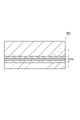
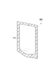
- FIG. 1 is a schematic cross-sectional view showing a laminated body according to an embodiment.
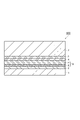
- FIG. 2 is a schematic cross-sectional view showing a laminated body according to an embodiment.
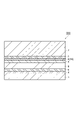
- FIG. 3 is a schematic cross-sectional view showing a laminated body according to an embodiment.
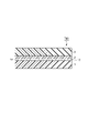
- FIG. 4 is a schematic cross-sectional view showing a laminated body according to an embodiment.
- FIG. 5 is a schematic cross-sectional view showing a laminated body according to an embodiment.
- FIG. 6 is a schematic cross-sectional view showing a laminated body according to an embodiment.
- FIG. 7 is a schematic cross-sectional view showing a laminated body according to an embodiment.
- FIG. 8 is a schematic cross-sectional view showing a standing pouch according to an embodiment.
- FIG. 9 is a schematic cross-sectional view showing a laminated body according to an embodiment.
- the configuration of the first side surface may be applied to the second side surface
- the configuration of the second side surface may be applied to the first side surface
- FIG. 1 is a schematic cross-sectional view showing a laminated body according to an embodiment.
- the laminate 100 shown in FIG. 1 includes a base material layer 1, an adhesive layer 2, and a sealant layer 3 in this order.
- FIG. 2 is a schematic cross-sectional view showing a laminated body according to another embodiment.
- the laminate 200 shown in FIG. 2 further includes a printing layer 4 between the base material layer 1 and the adhesive layer 2 in the laminate 100 shown in FIG. 1.
- FIG. 3 is a schematic cross-sectional view showing a laminated body according to another embodiment.
- the laminate 300 shown in FIG. 3 includes a base material layer 1, an undercoat layer 5, a gas barrier layer 10 composed of a vapor deposition layer 6, an adhesive layer 2, and a sealant layer 3 in this order.
- FIG. 4 is a schematic cross-sectional view showing a laminated body according to another embodiment.
- the laminated body 400 shown in FIG. 4 has the same structure as the laminated body 300 shown in FIG. 3 except that the gas barrier layer 10 is composed of the vapor-filmed layer 6 and the gas barrier coating layer 7.
- FIG. 5 is a schematic cross-sectional view showing a laminated body according to another embodiment.
- the laminate 500 shown in FIG. 5 further includes a print layer 4 between the gas barrier layer 10 and the adhesive layer 2 in the laminate 400 shown in FIG.
- FIG. 6 is a schematic cross-sectional view showing a laminated body according to another embodiment.
- the laminate 600 shown in FIG. 6 includes a base material layer 1, a printing layer 4, an adhesive layer 9, a resin layer 8, an undercoat layer 5, a gas barrier layer 10 composed of a vapor deposition layer 6, an adhesive layer 2, and a sealant layer. 3 is provided in this order.
- both the base material layer 1 and the sealant layer 3 are made of an unstretched film containing polyethylene as a main component.
- the resin layer 8 is made of an unstretched film containing polyethylene as a main component.
- the "main component” means a component having a content of 50% by mass or more in the unstretched film.
- the base material layer 1 is one outermost layer of the laminated body, and the sealant layer is the other outermost layer of the laminated body.
- the base material layer 1 is a layer serving as a support, and is made of an unstretched film containing polyethylene as a main component having a density of 0.940 g / cm 3 or more.
- the content of polyethylene in the base material layer 1 may be 50% by mass or more, 80% by mass or more, or 100% by mass, based on the total amount of the base material layer 1. It is preferable to use polyethylene as the material of the base material layer 1 from the viewpoint of recyclability. Further, the higher the content of polyethylene in the base material layer 1, the better the recyclability.
- the polyethylene contained in the base material layer 1 may be an acid-modified polyethylene obtained by graft-modifying polyethylene with an unsaturated carboxylic acid, an acid anhydride of an unsaturated carboxylic acid, an ester of an unsaturated carboxylic acid, or the like. ..
- the density of polyethylene contained in the base material layer 1 is 0.940 g / cm 3 or more, preferably 0.945 g / cm 3 or more, and more preferably 0.950 g / cm 3 or more.
- the density of polyethylene is 0.940 g / cm 3 or more, it becomes easy to fuse only the sealant layer 3 at the time of heat sealing when the laminate is formed into a bag shape, so that the bag making suitability is good.
- the density of polyethylene is 0.940 g / cm 3 or more, the printability becomes good when the print layer 4 is formed on the base material layer 1.
- the density of polyethylene is 0.940 g / cm 3 or more, it is easy to prevent the base material layer 1 from stretching and wrinkling during the roll processing, and the vapor deposition layer 6 is provided on the base material layer 1. In this case, it is easy to prevent the vapor deposition layer 6 from cracking.
- the structure of the base material layer 1 may be a multilayer structure including a plurality of unstretched films each containing polyethylene having different densities as a main component.
- the base material layer 1 may be appropriately multi-layered in consideration of processability, rigidity, waist strength, heat resistance, powder removal during transportation, and the like of the film constituting the base material layer 1.
- the density of the film When the density of the film is measured as the base material layer 1, the density needs to be 0.940 g / cm 3 or more. Further, the content of the slip agent, the antistatic agent and the like may be changed in each layer for laminating.
- the base material layer 1 having a plurality of layers can be laminated and formed into a film by extrusion coating, coextrusion coating, sheet molding, coextrusion blow molding, or the like.
- the total thickness of the base material layer 1 including the plurality of layers is preferably about 10 to 100 ⁇ m, more preferably 15 to 50 ⁇ m.
- the unstretched film constituting the base material layer 1 may have a molecular orientation (MOR) of 1.07 or less, 1.05 or less, or 1.04 or less.
- MOR molecular orientation
- the degree of molecular orientation can be measured by a molecular orientation meter.
- the base material layer 1 preferably has a heat shrinkage rate of 3% or less in the traveling direction (MD direction) and the vertical direction (TD direction) after being heated at 100 ° C. for 15 minutes, and more preferably 2% or less. It is preferably 1.5% or less, and more preferably 1.5% or less.
- MD direction traveling direction
- TD direction vertical direction
- the heat shrinkage rate of the base material layer 1 is within the above range, it is easy to prevent the base material layer 1 from stretching and wrinkling during the roll processing, and it is easy to suppress the occurrence of cracks in the vapor deposition layer 6.
- the heat shrinkage rate (%) is a value calculated by the following formula.
- Heat shrinkage rate (%) ⁇ (length before heating-length after heating) / length before heating ⁇ x 100
- the procedure for measuring the heat shrinkage rate is as follows. (1) The base material layer 1 is cut into 20 cm ⁇ 20 cm and used as a measurement sample. (2) Draw a 10 cm line in the MD direction or TD direction of the measurement sample (length before heating). (3) The measurement sample is heated at 100 ° C. for 15 minutes. (4) Measure the length of the written line in the MD direction or the TD direction (length after heating). (5) The heat shrinkage rate is calculated from the above formula.
- the thickness of the base material layer 1 is not particularly limited.
- the thickness can be 6 to 200 ⁇ m depending on the application, but may be 9 to 50 ⁇ m or 12 to 38 ⁇ m from the viewpoint of obtaining excellent impact resistance and excellent bag making suitability. ..
- the substrate layer 1 is subjected to corona treatment and plasma on the laminated surface within a range that does not impair the barrier performance.
- Various pretreatments such as treatment, low temperature plasma treatment, frame treatment, chemical treatment, solvent treatment, ozone treatment, etc. may be performed, or a coat layer such as an easy-adhesion layer may be provided.
- the base material layer 1 may contain additives such as fillers, antiblocking agents, antistatic agents, plasticizers, lubricants, and antioxidants. Any one of these additives may be used alone, or two or more thereof may be used in combination.
- An undercoat layer (anchor coat layer) 5 may be provided on the surface of the base material layer 1 on which the thin-film deposition layer 6 is laminated.
- the undercoat layer 5 improves the adhesion performance between the base material layer 1 and the vapor deposition layer 6, improves the smoothness of the surface of the base material layer 1, and suppresses the occurrence of cracks in the vapor deposition layer 6 due to the elongation of the base material layer 1. , Can be produced. By improving the smoothness, it becomes easy to form the vapor-filmed layer 6 uniformly without defects, and it is easy to develop a high barrier property.
- the undercoat layer 5 can be formed by using a composition for forming an undercoat layer (anchor coating agent).
- the resin used for the anchor coating agent examples include acrylic resin, epoxy resin, acrylic urethane resin, polyester polyurethane resin, and polyether polyurethane resin.
- the resin used for the anchor coating agent an acrylic urethane resin and a polyester polyurethane resin are preferable from the viewpoint of heat resistance and interlayer adhesion strength.
- the undercoat layer 5 can be formed by using these resins or an anchor coating agent containing a component that reacts to form these resins.
- the thickness of the undercoat layer 5 is not particularly limited, but is preferably in the range of 0.01 to 5 ⁇ m, more preferably in the range of 0.03 to 3 ⁇ m, and more preferably in the range of 0.05 to 2 ⁇ m. Is particularly preferable. When the thickness of the undercoat layer 5 is at least the above lower limit value, more sufficient interlayer adhesion strength tends to be obtained, while when it is at least the above upper limit value, the desired gas barrier property tends to be easily developed.
- a known coating method can be used without particular limitation, and a dipping method (dipping method); a spray, a coater, a printing machine, a brush, or the like is used.
- the method can be mentioned.
- the types of coaters and printing machines used in these methods and their coating methods include gravure coaters such as direct gravure method, reverse gravure method, kiss reverse gravure method, and offset gravure method, reverse roll coater, and micro gravure. Examples include coaters, chamber doctor combined coaters, air knife coaters, dip coaters, bar coaters, comma coaters, and die coaters.
- the amount of the undercoat layer 5 applied is preferably 0.01 to 5 g / m 2 per 1 m 2 after the anchor coating agent is applied and dried, and 0.03 to 3 g / m 2 is preferable. Is more preferable.
- the mass per 1 m 2 after applying the anchor coating agent and drying is at least the above lower limit value, the film formation tends to be sufficient, while when it is at least the above upper limit value, it is easy to sufficiently dry. The solvent tends to be difficult to remain.
- the method for drying the undercoat layer 5 is not particularly limited, but a method by natural drying, a method of drying in an oven set to a predetermined temperature, a dryer attached to the coater, for example, an arch dryer, a floating dryer, a drum, etc. Examples thereof include a method using a dryer, an infrared dryer, and the like. Further, the drying conditions can be appropriately selected depending on the method of drying. For example, in the method of drying in an oven, it is preferable to dry at a temperature of 60 to 100 ° C. for about 1 second to 2 minutes.
- a polyvinyl alcohol-based resin can be used instead of the above-mentioned resin.
- the polyvinyl alcohol-based resin may have a vinyl alcohol unit obtained by saponifying vinyl ester units, and examples thereof include polyvinyl alcohol (PVA) and ethylene-vinyl alcohol copolymer (EVOH).
- the PVA for example, vinyl esters such as vinyl acetate, vinyl formate, vinyl propionate, vinyl valerate, vinyl caprate, vinyl laurate, vinyl stearate, vinyl pivalate, and vinyl versatic acid are independently polymerized. Then, the saponified resin is mentioned.
- the PVA may be a copolymerized or post-modified modified PVA.
- the modified PVA can be obtained, for example, by copolymerizing a vinyl ester with an unsaturated monomer copolymerizable with the vinyl ester and then saponifying the vinyl ester.
- Examples of unsaturated monomers copolymerizable with vinyl esters include olefins such as ethylene, propylene, isobutylene, ⁇ -octene, ⁇ -dodecene, and ⁇ -octadecene; 3-butene-1-ol and 4-pentin-1-ol.
- 5-Hexen-1-ol and other hydroxy group-containing ⁇ -olefins acrylic acid, methacrylic acid, crotonic acid, maleic acid, maleic anhydride, itaconic acid, undecylenic acid and other unsaturated acids; Nitrile; amides such as diacetone acrylamide, acrylamide, and methacrylamide; olefin sulfonic acids such as ethylene sulfonic acid, allyl sulfonic acid, and methallyl sulfonic acid; alkyl vinyl ethers, dimethyl allyl vinyl ketones, N-vinylpyrrolidone, vinyl chloride, vinyl ethylene.
- Vinyl compounds such as carbonate, 2,2-dialkyl-4-vinyl-1,3-diokinlan, glycerin monoallyl ether, 3,4-diacetoxy-1-butene; vinylidene chloride, 1,4-diacetoxy-2-butene, Examples include vinylene carbonate and the like.
- the degree of polymerization of PVA is preferably 300 to 3000. When the degree of polymerization is 300 or more, the barrier property is likely to be improved, and when it is 3000 or less, the viscosity is too high and it is easy to suppress the deterioration of the coating suitability.
- the degree of saponification of PVA is preferably 90 mol% or more, more preferably 95 mol% or more, still more preferably 99 mol% or more. Further, the saponification degree of PVA may be 100 mol% or less or 99.9 mol% or less.
- the degree of polymerization and saponification of PVA can be measured according to the method described in JIS K 6726 (1994).
- EVOH is generally the co-weight of ethylene with an acid vinyl ester such as vinyl acetate, vinyl formate, vinyl propionate, vinyl valerate, vinyl caprate, vinyl laurate, vinyl stearate, vinyl pivalate, vinyl versatic acid and the like. Obtained by converting the coalescence into Ken.
- an acid vinyl ester such as vinyl acetate, vinyl formate, vinyl propionate, vinyl valerate, vinyl caprate, vinyl laurate, vinyl stearate, vinyl pivalate, vinyl versatic acid and the like. Obtained by converting the coalescence into Ken.
- the degree of polymerization of EVOH is preferably 300 to 3000. When the degree of polymerization is 300 or more, the barrier property is likely to be improved, and when it is 3000 or less, the viscosity is too high and it is easy to suppress the deterioration of the coating suitability.
- the saponification degree of the vinyl ester component of EVOH is preferably 90 mol% or more, more preferably 95 mol% or more, still more preferably 99 mol% or more. Further, the saponification degree of EVOH may be 100 mol% or less or 99.9 mol% or less.
- the degree of saponification of EVOH is determined from the peak area of hydrogen atoms contained in the vinyl ester structure and the peak area of hydrogen atoms contained in the vinyl alcohol structure by performing nuclear magnetic resonance ( 1 H-NMR) measurement.
- the ethylene unit content of EVOH is 10 mol% or more, more preferably 15 mol% or more, further preferably 20 mol% or more, and particularly preferably 25 mol% or more.
- the ethylene unit content of EVOH is preferably 65 mol% or less, more preferably 55 mol% or less, still more preferably 50 mol% or less.
- the gas barrier property or the dimensional stability under high humidity can be kept good.
- the gas barrier property can be enhanced.
- the ethylene unit content of EVOH can be determined by the NMR method.
- examples of the method for forming the undercoat layer 5 include coating with a polyvinyl alcohol-based resin solution, multi-layer extrusion, and the like.
- the constituent material of the vapor-deposited layer 6 examples include inorganic oxides such as aluminum oxide, silicon oxide, magnesium oxide, and tin oxide. From the viewpoint of transparency and barrier property, the inorganic oxide may be selected from the group consisting of aluminum oxide, silicon oxide, and magnesium oxide. Further, from the viewpoint of excellent tensile stretchability during processing, the vapor deposition layer 6 is preferably a layer containing silicon oxide. By using the thin-film deposition layer 6, it is possible to obtain a high barrier property in a very thin layer within a range that does not affect the recyclability of the laminated body.
- the O / Si ratio of the thin-film deposition layer 6 is 1.7 or more.
- the O / Si ratio is 1.7 or more, the content ratio of metallic Si is suppressed and good transparency is easily obtained.
- the O / Si ratio is preferably 2.0 or less.
- the crystallinity of SiO becomes high and the vapor deposition layer 6 can be prevented from becoming too hard, and good tensile resistance can be obtained. As a result, it is possible to prevent cracks from being generated in the vapor-deposited layer 6 when the adhesive layer 2 is laminated.
- the base material layer 1 may shrink due to the heat during the boiling process even after molding into the packaging bag, but the O / Si ratio of 2.0 or less makes it easy for the vapor deposition layer 6 to follow the shrinkage. It is possible to suppress the deterioration of the barrier property. From the viewpoint of more sufficiently obtaining these effects, the O / Si ratio of the vapor deposition layer 6 is preferably 1.75 or more and 1.9 or less, and more preferably 1.8 or more and 1.85 or less.
- the O / Si ratio of the thin-film deposition layer 6 can be determined by X-ray photoelectron spectroscopy (XPS).
- XPS X-ray photoelectron spectroscopy
- the measuring device is an X-ray photoelectron spectroscopic analyzer (manufactured by JEOL Ltd., trade name: JPS-90MXV), and the X-ray source is a non-monochromatic MgK ⁇ (1253.6 eV), 100 W (10 kV-10 mA). ) Can be measured with the X-ray output.
- a relative sensitivity factor of 2.28 for O1s and 0.9 for Si2p can be used, respectively.
- the film thickness of the thin-film deposition layer 6 is preferably 10 nm or more and 50 nm or less.
- the film thickness is 10 nm or more, sufficient gas barrier properties can be obtained.
- the film thickness is 50 nm or less, it is possible to suppress the generation of cracks due to deformation due to the internal stress of the thin film and suppress the deterioration of the gas barrier property.
- the film thickness of the vapor deposition layer 6 is more preferably 20 nm or more and 40 nm or less.
- the thin-film deposition layer 6 can be formed, for example, by vacuum film formation.
- a physical vapor deposition method or a chemical vapor deposition method can be used.
- the physical vapor deposition method include, but are not limited to, a vacuum vapor deposition method, a sputtering method, and an ion plating method.
- the chemical vapor deposition method include, but are not limited to, a thermal CVD method, a plasma CVD method, and an optical CVD method.
- resistance heating type vacuum deposition method In the above vacuum film formation, resistance heating type vacuum deposition method, EB (Electron Beam) heating type vacuum deposition method, induction heating type vacuum deposition method, sputtering method, reactive sputtering method, dual magnetron sputtering method, plasma chemical vapor deposition method (PECVD method) and the like are particularly preferably used.
- EB Electro Beam
- induction heating type vacuum deposition method sputtering method, reactive sputtering method, dual magnetron sputtering method, plasma chemical vapor deposition method (PECVD method) and the like
- PECVD method plasma chemical vapor deposition method
- the heating means of the vacuum vapor deposition method it is preferable to use any one of an electron beam heating method, a resistance heating method, and an induction heating method.
- the adhesive layer 2 is provided at a position in contact with the sealant layer 3 and is a layer for adhering the sealant layer 3 to another layer.
- the other layers are, for example, a base material layer 1, a printing layer 4, a vapor deposition layer 6, or a gas barrier coating layer 7.
- a known adhesive can be used as the adhesive constituting the adhesive layer 2.
- a polyester-isocyanate resin, a urethane resin, a polyether resin, or the like can be used as the material of the adhesive.
- the adhesive layer 2 may be a gas barrier adhesive layer having a gas barrier property.
- the gas barrier property of the laminated body can be improved.
- the adhesive layer 2 is preferably a gas barrier adhesive layer.
- the oxygen permeability of the gas barrier adhesive layer is preferably 150 cc / m 2 ⁇ day ⁇ atm or less, more preferably 100 cc / m 2 ⁇ day ⁇ atm or less, and 80 cc / m 2 ⁇ day ⁇ atm. It is more preferably 50 cc / m 2 ⁇ day ⁇ atm or less, and particularly preferably 50 cc / m 2 ⁇ day ⁇ atm or less.
- the gas barrier property of the laminated body can be sufficiently improved. Further, when the gas barrier adhesive layer is provided at a position in contact with the vapor deposition layer 6, the oxygen permeability is within the above range, and even if the vapor deposition layer 6 is slightly cracked, the gap thereof. The gas barrier adhesive layer can enter and complement the gas barrier property, and the deterioration of the gas barrier property can be suppressed.
- the gas barrier adhesive layer may be a layer made of a cured product of the gas barrier adhesive.
- the gas barrier adhesive layer is formed by using a gas barrier adhesive that can exhibit gas barrier properties after curing.
- the gas barrier adhesive used for forming the gas barrier adhesive layer include an epoxy adhesive and a polyester / polyurethane adhesive.
- Specific examples of the gas barrier adhesive that can exhibit gas barrier properties after curing include "Maxive” manufactured by Mitsubishi Gas Chemical Company, "Paslim” manufactured by DIC Corporation, and the like.
- the surface of the gas barrier adhesive layer preferably has a logarithmic decrement of 0.1 or less, more preferably 0.05 or less, as measured by a rigid pendulum type physical property tester at 30 ° C. It is more preferably 0.03 or less.
- the logarithmic decrement of the surface of the gas barrier adhesive layer is within the above range, so that the gas barrier property of the laminated body can be further improved and the gas barrier property can be further improved. It is possible to further suppress the deterioration of the gas barrier property after bending.
- the thickness of the gas barrier adhesive layer is preferably 50 times or more the thickness of the vapor deposition layer 6.
- the thickness of the gas barrier adhesive layer is within the above range, cracking of the vapor-deposited layer 6 can be more sufficiently suppressed, and the gas barrier property of the laminated body can be further improved.
- the thickness of the gas barrier adhesive layer is within the above range, it is possible to obtain a cushioning property for alleviating an impact from the outside, and it is possible to prevent the vapor-deposited layer 6 from being cracked by the impact.
- the thickness of the gas barrier adhesive layer is preferably 300 times or less the thickness of the vapor-deposited layer 6.
- the thickness of the adhesive layer 2 is preferably 0.1 to 20 ⁇ m, more preferably 0.5 to 10 ⁇ m, and even more preferably 1 to 5 ⁇ m.
- the thickness of the adhesive layer 2 is at least the above lower limit value, the adhesion between the sealant layer 3 and other layers can be further improved. Further, when the thickness of the adhesive layer 2 is at least the above lower limit value, it is possible to obtain a cushioning property for alleviating an impact from the outside. On the other hand, when the thickness of the adhesive layer 2 is not more than the above upper limit value, the flexibility of the laminated body tends to be sufficiently maintained.
- the adhesive for forming the adhesive layer 2 is, for example, a bar coating method, a dipping method, a roll coating method, a gravure coating method, a reverse coating method, an air knife coating method, a comma coating method, a die coating method, a screen printing method, and a spray. It can be applied by a coating method, a gravure offset method, or the like.
- the temperature at which the coating film formed by applying this adhesive is dried can be, for example, 30 to 200 ° C, preferably 50 to 180 ° C.
- the temperature at which the coating film is cured can be, for example, room temperature to 70 ° C., preferably 30 to 60 ° C.
- the adhesive layer 2 and the vapor-film deposition layer 6 are in direct contact with each other (no other layer is interposed between them) from the viewpoint of preventing cracking of the vapor-film deposition layer 6. .. Therefore, it is preferable that the adhesive layer 2 is formed by applying the adhesive on the vapor-deposited layer 6 and drying and curing the adhesive layer 2. Similarly, it is preferable that the thin-film deposition layer 6 and the undercoat layer 5 are in direct contact with each other (no other layer is interposed between them) from the viewpoint of preventing the vapor-film deposition layer 6 from cracking.
- the gas barrier covering layer 7 protects the vapor-filmed layer 6 and contributes to the improvement of the gas barrier property, thereby exhibiting a high gas barrier property due to a synergistic effect with the vapor-filmed layer 6.
- the gas barrier coating layer 7 may contain a water-soluble polymer, may contain at least one of a metal alkoxide and a hydrolyzate thereof, and may contain a water-soluble polymer, a metal alkoxide and a hydrolyzate thereof. It may contain at least one of them.
- the water-soluble polymer may have a hydroxy group.
- the gas barrier coating layer 7 can be formed through a step of forming a coating film containing the above components on the surface of the vapor-film deposition layer 6.
- water-soluble polymer examples include polyvinyl alcohol, polyvinylpyrrolidone, starch, methyl cellulose, carboxymethyl cellulose, sodium alginate and the like.
- polyvinyl alcohol hereinafter abbreviated as PVA
- PVA polyvinyl alcohol
- the PVA referred to here is generally obtained by saponifying polyvinyl acetate.
- a so-called partially saponified PVA in which several tens of percent of acetic acid groups remain and only a few percent of acetic acid groups remain. Complete PVA or the like can be used.
- the water-soluble polymer may form an organic-inorganic composite by hydrolysis and dehydration condensation (for example, sol-gel method) together with a metal alkoxide and / or a hydrolyzate thereof.
- the metal alkoxide is a compound represented by the following general formula.
- M represents a metal atom such as Si, Ti, Al, Zr, R represents an alkyl group such as -CH 3 , -C 2 H 5 , and n represents an integer corresponding to the valence of M.
- Specific examples thereof include tetraethoxysilane [Si (OC 2 H 5 ) 4 ] and triisopropoxyaluminum [Al (O-iso-C 3 H 7 ) 3 ].
- Tetraethoxysilane and triisopropoxyaluminum are preferable because they are relatively stable in an aqueous solvent after hydrolysis.
- hydrolyzate and polymer of the metal alkoxide examples include the following compounds. ⁇ Hydrolyzes and polymers of tetraethoxysilane: silicic acid (Si (OH) 4 ), etc. ⁇ Hydrolyides and polymers of tripropoxyaluminum: aluminum hydroxide (Al (OH) 3 ), etc.
- the gas barrier coating layer 7 may further contain a silane coupling agent.
- silane coupling agent examples include compounds represented by the following general formulas.
- R 1 Si (OR 2 ) n R 1 indicates an organic functional group, and R 2 indicates an alkyl group such as CH 3 , C 2 H 5 and the like.
- R 1 indicates an organic functional group
- R 2 indicates an alkyl group such as CH 3 , C 2 H 5 and the like.
- ethyltrimethoxysilane vinyltrimethoxysilane, ⁇ -chloropropylmethyldimethoxysilane, ⁇ -chloropropyltrimethoxysilane, glycidoxypropyltrimethoxysilane, ⁇ -methacryloxypropyltrimethoxysilane, ⁇ -
- silane coupling agent such as methacryloxypropylmethyldimethoxysilane.
- an isocyanate compound or a known additive such as a dispersant, a stabilizer, a viscosity modifier, or a colorant is added to the gas barrier coating layer 7 as necessary, as long as the gas barrier property is not impaired. Is also possible.
- the thickness (thickness) of the gas barrier coating layer 7 is preferably in the range of 50 to 1000 nm, and more preferably in the range of 100 to 500 nm. When the film thickness is 50 nm or more, a more sufficient gas barrier property tends to be obtained, and when the film thickness is 1000 nm or less, the thin film tends to maintain sufficient flexibility.
- Examples of the solvent used for forming the coating film include water, methyl alcohol, ethyl alcohol, isopropyl alcohol, n-propyl alcohol, n-butyl alcohol, n-pentyl alcohol, dimethylsulfoxide, dimethylformamide and dimethylacetamide. , Toluene, hexane, heptane, cyclohexane, acetone, methyl ethyl ketone, diethyl ether, dioxane, tetrahydrofuran, ethyl acetate, butyl acetate. These solvents may be used alone or in combination of two or more.
- methyl alcohol, ethyl alcohol, isopropyl alcohol, toluene, ethyl acetate, methyl ethyl ketone and water are preferable from the viewpoint of coatability. Further, from the viewpoint of manufacturability, methyl alcohol, ethyl alcohol, isopropyl alcohol and water are preferable.
- Additives such as isocyanate compounds, silane coupling agents, dispersants, stabilizers, viscosity modifiers and colorants may be added to the coating liquid as necessary, as long as the gas barrier properties are not impaired.
- a silane compound (silane coupling agent) represented by the formula (R 1 Si (OR 2 ) 3 ) n may be added to the coating liquid.
- the organic functional group (R 1 ) is preferably a non-aqueous functional group such as vinyl, epoxy, methacryloxy, ureido and isocyanate.
- silane coupling agent examples include 1,3,5-tris (3-trialkoxysilylalkyl) isocyanurate, 3-glycidoxypropyltrimethoxysilane, and 2- (3,4 epoxycyclohexyl) ethyltrimethoxysilane. Can be mentioned.
- the gas barrier coating layer 7 can be formed through a step of applying a coating liquid on the surface of the vapor deposition layer 6.
- a coating liquid on the surface of the vapor deposition layer 6.
- the coating method the cast method, dipping method, roll coating method, gravure coating method, screen printing method, reverse coating method, spray coating method, kit coating method, die coating method, metering bar coating method, and chamber doctor are used together. Conventionally known methods such as a coating method and a curtain coating method can be used.
- the gas barrier coating layer 7 is formed by heating and drying the coating film formed by applying the coating liquid.
- the sealant layer 3 is a layer made of an unstretched film containing polyethylene as a main component.
- the content of polyethylene in the sealant layer 3 may be 50% by mass or more, 80% by mass or more, or 100% by mass based on the total amount of the sealant layer 3.
- the sealant layer 3 is a layer that imparts sealing properties by heat sealing in the laminated body.
- low-density polyethylene resin LDPE
- MDPE medium-density polyethylene resin
- LLDPE linear low-density polyethylene resin
- these polyethylene resins can be appropriately selected depending on the intended use and temperature conditions such as boiling treatment.
- the polyethylene contained in the sealant layer 3 may be an acid-modified polyethylene obtained by graft-modifying polyethylene with an unsaturated carboxylic acid, an acid anhydride of an unsaturated carboxylic acid, an ester of an unsaturated carboxylic acid, or the like.
- the density of polyethylene contained in the sealant layer 3 is preferably lower than that of polyethylene contained in the base material layer 1, more preferably less than 0.94 g / cm 3 , and 0.90 to 0.925 g / cm. It is more preferably 3 .
- the structure of the sealant layer 3 may be a multilayer structure including a plurality of unstretched films each containing polyethylene having different densities as a main component.
- the sealant layer 3 may be appropriately multi-layered in consideration of processability, rigidity, waist strength, heat resistance, powder removal during transportation, and the like of the film constituting the sealant layer 3.
- the density of the film is measured as the sealant layer 3, the density is preferably less than the density of the base material layer 1. Further, the content of additives and the like described later may be changed in each layer for laminating.
- the sealant layer 3 having a plurality of layers can be laminated and formed into a film by extrusion coating, coextrusion coating, sheet molding, coextrusion blow molding, or the like.
- additives such as flame retardants, slip agents, anti-blocking agents, antioxidants, light stabilizers, and tackifiers may be added to the sealant layer 3.
- the thickness of the sealant layer 3 is determined by the mass of the contents, the shape of the packaging bag, and the like, but a thickness of about 30 to 150 ⁇ m is preferable.
- Examples of the method for forming the sealant layer 3 include a method in which an unstretched film containing polyethylene as a main component is bonded with an adhesive for forming the adhesive layer 2 described above.
- the sealant layer 3 has various pretreatments such as corona treatment, plasma treatment, low temperature plasma treatment, frame treatment, chemical treatment, solvent treatment, and ozone treatment on the laminated surface. Or a coat layer such as an easy-adhesion layer may be provided.
- the print layer 4 is provided at a position visible from the outside of the laminated body for the purpose of displaying information about the contents, identifying the contents, or improving the design of the packaging bag.
- the printing method and printing ink are not particularly limited, and are appropriately selected from known printing methods and printing inks in consideration of printability on a film, designability such as color tone, adhesion, safety as a food container, and the like.
- a gravure printing method, an offset printing method, a gravure offset printing method, a flexo printing method, an inkjet printing method, or the like can be used. Above all, the gravure printing method can be preferably used from the viewpoint of productivity and high definition of the pattern.
- the surface of the layer (base material layer 1 or resin layer 8) forming the print layer 4 can be easily subjected to various pretreatments such as corona treatment, plasma treatment, and frame treatment.
- a coat layer such as an adhesive layer may be provided.
- the stacking position of the print layer 4 is not particularly limited.
- the printed layer 4 may be formed, for example, on the surface of the base material layer 1 on the sealant layer 3 side.
- the printed layer 4 may be formed on the surface of the gas barrier layer 10 on the sealant layer 3 side.
- the laminated body includes the resin layer 8
- the printed layer 4 may be formed on one surface of the resin layer 8.
- the print layer 4 is formed in advance on the surface of the base material layer 1 or the resin layer 8, and the base material layer 1 or the resin layer 8 on which the print layer 4 is formed is passed through the adhesive layer 2 or the adhesive layer 9. It may be laminated with another layer.
- the resin layer 8 is a layer made of an unstretched film containing polyethylene as a main component, which is arranged between the base material layer 1 and the sealant layer 3.
- the content of polyethylene in the resin layer 8 may be 50% by mass or more, 80% by mass or more, or 100% by mass, based on the total amount of the resin layer 8.
- the resin layer 8 can have the same structure as the base material layer 1. By providing the resin layer 8, it is possible to form a chewy laminate. Further, by providing the printing layer 4 on one surface of the base material layer 1 and the resin layer 8 and providing the gas barrier layer 10 on the other surface, the base film and the gas barrier layer 10 forming the printing layer 4 are formed. It can be separated from the base film to be printed.
- the risk of defects when forming the print layer and the risk of defects when forming the gas barrier layer can be separated, and the process of applying a heat load to one base film can be reduced. Can be done. Further, by providing the resin layer 8, it becomes easy to provide the printing layer 4 on the inner surface of the laminated body instead of the outer surface.
- the stacking position of the resin layer 8 is not particularly limited as long as it is between the base material layer 1 and the sealant layer 3.
- the resin layer 8 may be arranged between the gas barrier layer 10 and the base material layer 1.
- the resin layer 8 may be laminated with another layer via the adhesive layer 9.
- Adhesive layer 9 As the adhesive constituting the adhesive layer 9, a known adhesive can be used. As the material of the adhesive, for example, a polyester-isocyanate resin, a urethane resin, a polyether resin, or the like can be used. Further, as the adhesive, an adhesive for forming the above-mentioned adhesive layer 2 may be used.
- the heat fusion temperature difference between the base material layer 1 and the sealant layer 3 is preferably 10 ° C. or higher, more preferably 15 ° C. or higher, and further preferably 20 ° C. or higher. preferable.
- the heat fusion temperature of the base material layer 1 is preferably higher than the heat fusion temperature of the sealant layer, more preferably 100 ° C. or higher, still more preferably 120 ° C. or higher.
- the heat fusion temperature is at least the above lower limit value, it becomes easy to mold the laminate into a packaging bag or the like by heat sealing.
- the heat fusion temperature of the sealant layer 3 is preferably lower than the heat fusion temperature of the base material layer 1, more preferably 130 ° C. or lower, and further preferably 110 ° C. or lower.
- the heat fusion temperature is not more than the above upper limit value, it becomes easy to mold the laminate into a packaging bag or the like by heat sealing.
- the heat fusion temperature of each layer is the heat seal temperature of the layer to be measured, which is measured by a measurement method based on JIS Z0238: 1998. Specifically, when two layers to be measured are overlapped and heated with a heat seal tester at a pressure of 0.2 MPa for 1 second to form a heat seal portion, the heat seal portion that is heat-sealed and does not peel off is formed. The lowest temperature that can be formed is the heat fusion temperature.
- the films constituting the laminate can be polyethylene films.
- Such a laminate can be said to be a packaging material (monomaterial) made of a single material having excellent recyclability. From this viewpoint, the content of polyethylene in the laminate is 90% by mass or more, preferably 92.5% by mass or more.
- the thickness of the laminated body can be appropriately determined according to the application.
- the thickness of the laminate can be, for example, 0.01 to 10 mm, preferably 0.1 to 1.0 mm.
- the laminated body has a laminate strength of 2.5 N / 15 mm or more measured under the condition of a peeling speed of 300 mm / min based on the peeling adhesive strength test method (JIS K6854-2, ISO8510-2) at 180 degree peeling. It is preferable to have.
- the laminate strength is 2.5 N / 15 mm or more, even when a pouch filled with a liquid is formed in the contents, it is possible to prevent the bag from breaking when the bag is dropped.
- the laminate can be suitably used for various applications such as packaging products such as containers and bags, sheet molded products such as decorative sheets and trays, optical films, resin plates, various label materials, lid materials, and laminated tubes. It can be used particularly preferably for packaged products. Examples of the packaged product include a pillow bag, a standing pouch, a three-way seal bag, and a four-way seal bag.
- the packaging bag is made by making the above-mentioned laminate.
- the packaging bag may be formed into a bag shape by folding one laminated body in half so that the sealant layers face each other and then heat-sealing on three sides to form a bag shape.
- the bags may be formed into a bag shape by heat-sealing the four sides after stacking them so as to face each other.
- the packaging bag can contain the contents such as foods and medicines as the contents.
- the packaging bag can be subjected to heat sterilization treatment such as boiling treatment.
- Boil treatment is a method of moist heat sterilization to store foods, medicines, etc. Normally, although it depends on the contents, the packaging bag containing food or the like is subjected to moist heat sterilization treatment under the conditions of 60 to 100 ° C. and atmospheric pressure for 10 to 120 minutes.
- the boiling treatment is usually carried out at 100 ° C. or lower using a hot water tank.
- a hot water tank there are a batch type in which the material is immersed in a hot water tank at a constant temperature and treated for a certain period of time and then taken out, and a continuous type in which the inside of the hot water tank is passed through a tunnel type for treatment.
- the packaging bag of the present embodiment can also be suitably used for the purpose of applying a boil treatment.
- the packaging bag may have a shape having a bent portion (bent portion) such as a standing pouch.
- the packaging bag of the present embodiment can maintain high adhesion even in a shape having a bent portion.
- FIG. 7 is a schematic cross-sectional view of the laminated body 700 according to the present embodiment.
- the laminate 700 includes a base material layer (base material) 1, a gas barrier layer 10, an adhesive layer (adhesive layer) 2, and a sealant layer (heat seal layer) 3.
- the base material layer 1 is an unstretched film made of polyethylene. As a result, shrinkage and curl during processing of the laminated body 700 can be suppressed, and workability in the bag making and filling / sealing processes can be stabilized.
- the haze value of the unstretched film is preferably 45% or less, more preferably 30% or less.
- the haze value in the present disclosure is defined as measured in accordance with JIS K7105.
- the unstretched film may be produced by the method described later, or a commercially available film may be obtained.
- An image may be formed on the surface of the base material layer 1. It is preferable to form an image on the first surface 1a on the side where the gas barrier layer 10 is formed because deterioration over time due to contact with the outside air can be prevented.
- the image to be formed is not particularly limited, and may be characters, patterns, symbols, combinations thereof, and the like.
- the image formation on the base material layer is performed using an ink derived from biomass. This makes it possible to produce a packaging material having a smaller environmental load by using the laminated body 700.
- the method for forming an image is not particularly limited, and various conventionally known printing methods such as a gravure printing method, an offset printing method, and a flexographic printing method can be mentioned. Of these, the flexographic printing method is preferable from the viewpoint of environmental load.
- Polyethylene contained in the base material layer as a main component includes high-density polyethylene (HDPE), medium-density polyethylene (MDPE), low-density polyethylene (LDPE), linear low-density polyethylene (LLDPE), and ultra-low-density polyethylene (VLDPE). ) Can be used.
- HDPE high-density polyethylene
- MDPE medium-density polyethylene
- LDPE low-density polyethylene
- LLDPE linear low-density polyethylene
- VLDPE ultra-low-density polyethylene
- polyethylene having a density of 0.945 g / cm 3 or more can be used.
- medium density polyethylene polyethylene having a density of 0.925 g / cm 3 or more and less than 0.945 g / cm 3 can be used.
- low-density polyethylene polyethylene having a density of 0.900 g / cm 3 or more and less than 0.925 g / cm 3 can be used.
- linear low-density polyethylene polyethylene having a density of 0.900 g / cm 3 or more and less than 0.925 g / cm 3 can be used.
- ultra-low density polyethylene polyethylene having a density of less than 0.900 g / cm 3 can be used.
- high-density polyethylene is preferable from the viewpoint of printability, strength and heat resistance.
- polyethylenes having different densities and branches can be obtained by appropriately selecting a polymerization method.
- a multisite catalyst such as a Cheegler-Natta catalyst or a single site catalyst such as a metallocene-based catalyst is used as a polymerization catalyst by any of gas phase polymerization, slurry polymerization, solution polymerization, and high pressure ion polymerization. It is preferable to carry out in one stage or in multiple stages of two or more stages.
- the above-mentioned single-site catalyst is a catalyst capable of forming a uniform active species, and is usually prepared by contacting a metallocene-based transition metal compound or a non-metallocene-based transition metal compound with an activation co-catalyst. ..
- a single-site catalyst is preferable because it has a uniform active site structure and can polymerize a polymer having a high molecular weight and a high uniformity structure as compared with a multi-site catalyst.
- As the single-site catalyst it is particularly preferable to use a metallocene-based catalyst.
- the metallocene-based catalyst is a catalyst containing a transition metal compound of Group IV of the Periodic Table containing a ligand having a cyclopentadienyl skeleton, a cocatalyst, an organometallic compound if necessary, and each catalyst component of the carrier. be.
- the cyclopentadienyl skeleton is a cyclopentadienyl group, a substituted cyclopentadienyl group or the like.
- the substituted cyclopentadienyl group includes a hydrocarbon group having 1 to 30 carbon atoms, a silyl group, a silyl substituted alkyl group, a silyl substituted aryl group, a cyano group, a cyanoalkyl group, a cyanoaryl group, a halogen group, a haloalkyl group, and a halosilyl.
- the substituted cyclopentadienyl group may have two or more substituents, and the substituents are bonded to each other to form a ring, and an indenyl ring, a fluorenyl ring, an azulenyl ring, a hydrogenator thereof, or the like can be formed. It may be formed. Rings formed by bonding substituents to each other may further have substituents to each other.
- transition metal compound of Group IV of the Periodic Table containing a ligand having a cyclopentadienyl skeleton examples include zirconium, titanium and hafnium, and zirconium and hafnium are particularly preferable.
- the transition metal compound usually has two ligands having a cyclopentadienyl skeleton, and the ligands having each cyclopentadienyl skeleton are preferably bonded to each other by a bridging group.
- cross-linking group examples include a substituted silylene group such as an alkylene group having 1 to 4 carbon atoms, a silylene group, a dialkylsilylene group and a diarylcyrylene group, and a substituted gelmilene group such as a dialkylgelmylene group and a diarylgelmylene group. It is preferably a substituted silylene group.
- the above-mentioned transition metal compound of Group IV of the Periodic Table containing a ligand having a cyclopentadienyl skeleton can have one or a mixture of two or more as a catalytic component.
- the co-catalyst is one that can effectively use the above-mentioned transition metal compound of Group IV of the Periodic Table as a polymerization catalyst, or can balance the ionic charge in a catalytically activated state.
- Co-catalysts include benzene-soluble organoxane, which is an organoaluminum oxy compound, benzene-insoluble organoaluminum oxy compound, ion-exchangeable layered silicate, boron compound, active hydrogen group-containing or non-active hydrogen group-containing or non-coordinating anion. Examples thereof include ionic compounds, lanthanoid salts such as lanthanum oxide, tin oxide, and phenoxy compounds containing a fluoro group.
- the transition metal compound of Group IV of the Periodic Table which contains a ligand having a cyclopentadienyl skeleton, may be used by being carried on a carrier of an inorganic or organic compound.
- a porous oxide of an inorganic or organic compound is preferable, and specifically, an ion-exchangeable layered silicate such as montmorillonite, SiO 2 , Al 2 O 3 , MgO, ZrO 2 , TiO 2 , B 2 O. 3 , CaO, ZnO, BaO, ThO 2 , and mixtures thereof.
- organometallic compound used as needed include organoaluminum compounds, organomagnesium compounds, and organozinc compounds. Of these, organoaluminum is preferably used.
- Copolymers of ethylene and other monomers can also be used as long as the characteristics of the present disclosure are not impaired.
- the ethylene copolymer include a copolymer composed of ethylene and an ⁇ -olefin having 3 to 20 carbon atoms.
- ⁇ -olefins having 3 to 20 carbon atoms include propylene, 1-butene, 1-pentene, 1-hexene, 1-octene, 1-decene, 1-dodecene, 1-tetradecene, 1-hexadecene, 1-octadecene, and the like. Examples thereof include 1-eicosene, 3-methyl-1-butene, 4-methyl-1-pentene and 6-methyl-1-heptene.
- a copolymer with vinyl acetate, acrylic acid ester, or the like may be used as long as the object of the present disclosure is not impaired.
- biomass-derived ethylene may be used instead of ethylene obtained from fossil fuel. Since such biomass-derived polyethylene is a carbon-neutral material, it can be used as a packaging material with even less environmental impact.
- biomass-derived polyethylene can be produced, for example, by a method as described in Japanese Patent Application Laid-Open No. 2013-177531. Further, commercially available biomass-derived polyethylene (for example, green PE commercially available from Braskem) may be used.
- Polyethylene recycled by mechanical recycling can also be used for the base material layer 1.
- mechanical recycling generally means that the recovered polyethylene film or the like is crushed and alkaline-cleaned to remove stains and foreign substances on the film surface, and then dried under high temperature and reduced pressure for a certain period of time to stay inside the film. This is a method in which a contaminant is diffused and decontaminated to remove stains on a film made of polyethylene, and the film is returned to polyethylene again.
- the base material layer 1 can contain additives as long as the characteristics of the present disclosure are not impaired.
- the additive include a cross-linking agent, an antioxidant, an anti-blocking agent, a slip agent, an ultraviolet absorber, a light stabilizer, a filler, a reinforcing agent, an antistatic agent, a pigment, and a resin for modification.
- the thickness of the base material layer 1 is preferably 10 ⁇ m or more and 50 ⁇ m or less, and more preferably 12 ⁇ m or more and 35 ⁇ m or less. By setting the thickness of the base material layer 1 to 10 ⁇ m or more, the strength of the laminated body 700 can be improved. Further, by setting the thickness of the base material layer 1 to 50 ⁇ m or less, the processability of the laminated body 700 can be improved.
- the base material layer 1 can be produced by forming a film of polyethylene by a T-die method, an inflation method, or the like.
- the melt flow rate (MFR) of polyethylene is preferably 3 g / 10 minutes or more and 20 g / 10 minutes or less.
- MFR melt flow rate
- the MFR of polyethylene is preferably 0.5 g / 10 minutes or more and 5 g / 10 minutes or less.
- the processability of the laminated body 700 can be improved.
- the film forming property can be improved.
- the base material layer 1 is preferably surface-treated.
- the surface treatment method is not particularly limited, for example, corona discharge treatment, ozone treatment, low temperature plasma treatment using oxygen gas and / or nitrogen gas, physical treatment such as glow discharge treatment, and oxidation using chemicals. Examples include chemical treatment such as treatment.
- an anchor coat layer (undercoat layer) may be formed by using a known anchor coating agent on the first surface 1a on which the gas barrier layer is formed. good. This makes it possible to improve the adhesion of the gas barrier layer made of a metal oxide.
- the anchor coating agent include polyester-based polyurethane resins and polyether-based polyurethane resins. From the viewpoint of heat resistance and interlayer adhesion strength, polyester polyurethane resin is preferable.
- the gas barrier layer 10 is provided on the first surface 1a side of the base material layer 1 directly or via another layer, and imparts oxygen barrier property and water vapor barrier property to the laminated body 700.
- the gas barrier layer examples include a vapor-deposited layer made of a metal oxide such as aluminum oxide, silicon oxide, magnesium oxide, and tin oxide.
- the metal oxide may be selected from the group consisting of aluminum oxide, silicon oxide, and magnesium oxide. Further, considering printability and cost, aluminum oxide and silicon oxide are selected. Further, from the viewpoint of excellent tensile stretchability during processing, it is more preferable to use a layer using silicon oxide.
- a thin-film vapor deposition layer made of a metal oxide for the gas barrier layer a high barrier property can be obtained with a very thin layer within a range that does not affect the recyclability of the gas barrier laminate.
- the O / Al ratio is preferably 1.4 or more.
- the O / Al ratio is 1.4 or more, the content ratio of unbonded aluminum atoms is suppressed and good transparency can be easily obtained.
- the O / Al ratio is preferably 1.7 or less.
- the crystallinity of AlO becomes high and it is possible to prevent the vapor-film deposition layer from becoming too hard, and good tensile resistance can be obtained.
- the base material layer 1 may shrink due to the heat during the boiling treatment, but if the O / Al ratio of the gas barrier layer 10 is 1.7 or less, this shrinkage is followed.
- the O / Al ratio of the vapor-filmed layer to be the gas barrier layer 10 is preferably 1.4 or more and 1.7 or less, and preferably 1.5 or more and 1.55 or less. More preferred.
- the O / Si ratio is preferably 1.7 or more.
- the O / Si ratio is 1.7 or more, the content ratio of unbonded silicon atoms is suppressed and good transparency can be easily obtained.
- the O / Si ratio is preferably 2.0 or less.
- the O / Si ratio is 2.0 or less, the crystallinity of SiO becomes high and the vapor deposition layer can be prevented from becoming too hard, and good tensile resistance can be obtained.
- the O / Si ratio of the gas barrier layer 10 is 2.0 or less, it is easy to follow the shrinkage described above, and it is possible to suppress the deterioration of the barrier property. From the viewpoint of obtaining these effects more sufficiently, the O / Si ratio of the vapor-filmed layer to be the gas barrier layer 10 is preferably 1.75 or more and 1.9 or less, and preferably 1.8 or more and 1.85 or less. More preferred.
- the film thickness of the vapor-filmed layer made of aluminum oxide is preferably 5 nm or more and 30 nm or less.
- the film thickness is 5 nm or more, sufficient gas barrier properties can be obtained.
- the film thickness is 30 nm or less, it is possible to suppress the generation of cracks due to deformation due to the internal stress of the thin film and suppress the deterioration of the gas barrier property. If the film thickness exceeds 30 nm, the cost tends to increase due to an increase in the amount of material used and a long film formation time, which is not preferable from an economical point of view.
- the film thickness of the vapor-film deposition layer is more preferably 7 nm or more and 15 nm or less.
- the film thickness of the thin-film vapor deposition layer made of silicon oxide is preferably 10 nm or more and 50 nm or less.
- the film thickness is 10 nm or more, sufficient gas barrier properties can be obtained.
- the film thickness is 50 nm or less, it is possible to suppress the generation of cracks due to deformation due to the internal stress of the thin film and suppress the deterioration of the gas barrier property. If the film thickness exceeds 50 nm, the cost tends to increase due to an increase in the amount of material used and a long film formation time, which is not preferable from an economical point of view.
- the film thickness of the vapor-film deposition layer is more preferably 20 nm or more and 40 nm or less.
- the thin-film deposition layer can be formed, for example, by vacuum film formation.
- a physical vapor deposition method or a chemical vapor deposition method can be used.
- the physical vapor deposition method include, but are not limited to, a vacuum vapor deposition method, a sputtering method, and an ion plating method.
- the chemical vapor deposition method include, but are not limited to, a thermal CVD method, a plasma CVD method, and an optical CVD method.
- resistance heating type vacuum deposition method In the above vacuum film formation, resistance heating type vacuum deposition method, EB (Electron Beam) heating type vacuum deposition method, induction heating type vacuum deposition method, sputtering method, reactive sputtering method, dual magnetron sputtering method, plasma chemical vapor deposition method (PECVD method) and the like are particularly preferably used.
- EB Electro Beam
- induction heating type vacuum deposition method sputtering method, reactive sputtering method, dual magnetron sputtering method, plasma chemical vapor deposition method (PECVD method) and the like
- PECVD method plasma chemical vapor deposition method
- the heating means of the vacuum vapor deposition method it is preferable to use any one of an electron beam heating method, a resistance heating method, and an induction heating method.
- the adhesive layer 2 is a layer containing at least one type of adhesive, and is provided between the gas barrier layer 10 and the sealant layer 3 to bond the two. Any adhesive such as a one-component curable type or a two-component curable urethane adhesive can be used for the adhesive layer 2. These adhesives may contain a layered inorganic compound for the purpose of further enhancing the barrier property.
- the thickness of the adhesive layer 2 is preferably 0.5 ⁇ m or more and 6 ⁇ m or less, more preferably 0.8 ⁇ m or more and 5 ⁇ m or less, and further preferably 1 ⁇ m or more and 4.5 ⁇ m or less.
- the adhesive layer 2 can be formed by various known methods such as a direct gravure roll coating method, a gravure roll coating method, a kiss coating method, a reverse roll coating method, a fonten method and a transfer roll coating method.
- the sealant layer 3 is made of polyethylene, and is joined by heat fusion (heat sealing) when forming a packaging material such as a standing pouch using the laminated body 700.
- the polyethylene constituting the sealant layer 3 can be selected from the group consisting of low density polyethylene (LDPE), linear low density polyethylene (LLDPE) and ultralow density polyethylene (VLDPE) from the viewpoint of heat sealability. preferable.
- the polyethylene of the base material layer 1 and the polyethylene of the sealant layer 3 may be the same or different. Further, from the viewpoint of environmental load, it is preferable that polyethylene derived from biomass or recycled polyethylene is used for the sealant layer.
- a copolymer of ethylene and other monomers can be used for the sealant layer 3 as long as the characteristics of the laminated body 700 are not impaired.
- the sealant layer 3 may be a single layer or may have a multilayer structure. If it has a multi-layer structure, it may include a layer containing at least one of medium density polyethylene and high density polyethylene.
- the sealant layer 3 is, for example, a layer containing at least one of low-density polyethylene, linear low-density polyethylene, and ultra-low-density polyethylene / a layer containing at least one of medium-density polyethylene and high-density polyethylene / low-density polyethylene. It can have a three-layer structure including a layer containing at least one of linear low-density polyethylene and ultra-low-density polyethylene. With such a configuration, it is possible to further improve the bag-making suitability and strength of the laminated body 700 while maintaining the heat-sealing property.
- the thickness of the sealant layer 3 can be appropriately changed according to the weight of the contents to be filled in the package material to be produced.
- the thickness of the sealant layer 3 is preferably 20 ⁇ m or more and 60 ⁇ m or less.
- the thickness is preferably 20 ⁇ m or more and 60 ⁇ m or less.
- the thickness of the sealant layer 3 is preferably 50 ⁇ m or more and 200 ⁇ m or less.
- the thickness is preferably 50 ⁇ m or more and 200 ⁇ m or less.
- the proportion of polyethylene in the laminate 700 is 90% by mass or more. There is. As a result, the laminated body 700 has high recyclability.
- the ratio (%) of polyethylene to the laminated body 700 can be calculated by the following formula (1). (Mass of base material layer 1 + mass of sealant layer 3) / mass of the entire laminated body ⁇ 100 ... (1)
- ⁇ Packaging bag and standing pouch> In a state where one laminated body 700 is bent while the sealant layer 3 is opposed to each other, or two laminated bodies 700 are stacked while the sealant layer 3 is opposed to each other, the sealant layer at the peripheral portion is left with the filling portion of the contents. When 3 is joined by heat sealing, a packaging bag made of the laminated body 700 can be formed.
- the standing pouch 900 as shown in FIG. 8 can be formed by using the laminated body 700.
- the above-mentioned packaging bag and standing pouch can contain various contents of solid, liquid, and gas.
- Patent Document 2 including a stretched high-density polyethylene film layer may easily break due to an impact when dropped. This phenomenon was particularly likely to occur when the contents were filled and sealed with a fluid liquid (including cases containing solids).
- the base material layer was torn along the molecular chain. It was considered that this was largely due to the fact that the crystal molecular chains were oriented in a certain direction in the stretched high-density polyethylene film which was the base material layer. Furthermore, it was also found that the crystal molecular chains are aligned not only in the plane direction but also in the thickness direction, which facilitates delamination.
- the unstretched polyethylene film is a film that has not been stretched, and spherical crystals (spherulite) of about 10 to 100 ⁇ m composed of randomly folded polyethylene molecular chains are formed.
- spherical crystals spherulite
- FIG. 9 shows the laminated body 800 according to the present embodiment.
- the laminate includes an adhesive layer 2A instead of the adhesive layer 2.
- the adhesive layer 2A is formed of a barrier adhesive (gas barrier adhesive) that can exhibit gas barrier properties after curing.
- gas barrier adhesive used for the adhesive layer 2A examples include epoxy adhesives, polyester / polyurethane adhesives, and the like. Specific examples include “Maxive” manufactured by Mitsubishi Gas Chemical Company, “Paslim” manufactured by DIC Corporation, and the like.
- the laminated body 800 according to the present embodiment has the same effect as the laminated body 700 according to the first embodiment. Further, by providing the adhesive layer 2A, the adhesive layer 2A protects the gas barrier layer and exhibits a barrier property independently of the gas barrier layer. For this reason, the gas barrier layer is subject to physical shocks such as rubbing generated during the manufacture of laminates, thermal shock due to heat sealing during the manufacture of standing pouches and filling of contents, and drop shocks during distribution of packaging bags filled with contents. It is possible to suppress the occurrence of cracks and to minimize the deterioration of the barrier even if cracks occur.
- the gas barrier layer may include a gas barrier coating layer (overcoat layer).
- the gas barrier coating layer can be provided between the vapor deposition layer and the adhesive layer.
- the gas barrier coating layer protects the thin-film deposition layer and exhibits barrier properties independently of the thin-film deposition layer.
- the gas barrier coating layer is mainly composed of an aqueous solution or a water / alcohol mixed solution containing at least one selected from the group consisting of a hydroxyl group-containing polymer compound, a metal alkoxide, a silane coupling agent, and a hydrolyzate thereof. It can be formed by using a composition for forming a gas barrier coating layer (hereinafter, also referred to as a coating agent).
- the coating agent preferably contains at least a silane coupling agent or a hydrolyzate thereof from the viewpoint of more sufficiently maintaining the gas barrier property after hot water treatment such as retort treatment, and is preferably a hydroxyl group-containing polymer compound, a metal alkoxide and the like. It is more preferable to contain at least one selected from the group consisting of those hydrolysates and a silane coupling agent or a hydrolyzate thereof, and a hydroxyl group-containing polymer compound or a hydrolyzate thereof, a metal alkoxide or a metal alkoxide or the like. It is more preferable to contain the hydrolyzate and the silane coupling agent or the hydrolyzate thereof.
- the metal alkoxide and the silane coupling agent are directly or preliminarily hydrolyzed in a solution in which a hydroxyl group-containing polymer compound which is a water-soluble polymer is dissolved in an aqueous (water or water / alcohol mixed) solvent. It can be prepared by mixing those that have undergone treatment such as alkoxide.
- hydroxyl group-containing polymer compound used in the coating agent examples include polyvinyl alcohol (PVA), polyvinylpyrrolidone, starch, methyl cellulose, carboxymethyl cellulose, sodium alginate and the like. It is preferable to use PVA as a coating agent because the gas barrier property of the gas barrier property coating layer is particularly excellent.
- the gas barrier coating layer is formed from a composition containing at least one selected from the group consisting of a metal alkoxide represented by the following general formula (I) and a hydrolyzate thereof from the viewpoint of obtaining excellent gas barrier properties.
- a metal alkoxide represented by the following general formula (I)
- M (OR 3 ) m (R 4 ) nm ...
- R 3 and R 4 are independently monovalent organic groups having 1 to 8 carbon atoms, and are preferably alkyl groups such as a methyl group and an ethyl group.
- M represents an n-valent metal atom such as Si, Ti, Al, Zr and the like.
- m is an integer from 1 to n.
- metal alkoxide examples include tetraethoxysilane [Si (OC 2 H 5 ) 4 ] and triisopropoxyaluminum [Al (O-2'-C 3 H 7 ) 3 ].
- Tetraethoxysilane and triisopropoxyaluminum are preferred because they are relatively stable in aqueous solvents after hydrolysis.
- Examples of the silane coupling agent include compounds represented by the following general formula (II). Si (OR 11 ) p (R 12 ) 3-p R 13 ... (II)
- R 11 represents an alkyl group such as a methyl group or an ethyl group.
- R 12 represents a monovalent organic group such as an alkyl group, an aralkyl group, an aryl group, an alkenyl group, an alkyl group substituted with an acryloxy group, or an alkyl group substituted with a methacryloxy group.
- R 13 represents a monovalent organic functional group.
- p indicates an integer of 1 to 3.
- the monovalent organic functional group represented by R 13 includes a glycidyloxy group, an epoxy group, a mercapto group, a hydroxyl group, an amino group, an alkyl group substituted with a halogen atom, or a monovalent organic functional group containing an isocyanate group. The group is mentioned.
- silane coupling agent examples include vinyltrimethoxysilane, ⁇ -chloropropylmethyldimethoxysilane, ⁇ -chloropropyltrimethoxysilane, glycidoxypropyltrimethoxysilane, ⁇ -methacryloxypropyltrimethoxysilane, and ⁇ -.
- silane coupling agent such as methacryloxypropylmethyldimethoxysilane.
- the silane coupling agent may be a polymerized multimer of the compound represented by the above general formula (II).
- a trimer is preferable, and 1,3,5-tris (3-trialkoxysilylalkyl) isocyanurate is more preferable.
- This is a condensed polymer of 3-isocyanate alkylalkoxysilane. It is known that the 1,3,5-tris (3-trialkoxysilylalkyl) isocyanurate has no chemical reactivity in the isocyanate portion, but the reactivity is ensured by the polarity of the nurate portion.
- 3-isocyanate alkylalkoxylan is added to an adhesive or the like like 3-isocyanate alkylalkoxylan, and is known as an adhesive improving agent. Therefore, by adding 1,3,5-tris (3-trialkoxysilylalkyl) isocyanurate to the hydroxyl group-containing polymer compound, the water resistance of the gas barrier coating layer can be improved by hydrogen bonding.
- 3-Isocyanatealkylalkoxylan is highly reactive and has low liquid stability, whereas 1,3,5-tris (3-trialkoxysilylalkyl) isocyanurate is not water-soluble due to its polarity. However, it is easy to disperse in an aqueous solution, and the liquid viscosity can be kept stable.
- the water resistance is equivalent to that of 3-isocyanatealkylalkoxylan and 1,3,5-tris (3-trialkoxysilylalkyl) isocyanurate.
- 1,3,5-Tris (3-trialkoxysilylalkyl) isocyanurate may be produced by thermal condensation of 3-isocyanatepropylalkoxysilane, and may contain the raw material 3-isocyanatepropylalkoxysilane. However, there is no particular problem. More preferably, it is 1,3,5-tris (3-trialkoxysilylpropyl) isocyanurate, and more preferably 1,3,5-tris (3-trimethoxysilylpropyl) isocyanurate. Since this methoxy group has a high hydrolysis rate and those containing a propyl group can be obtained at a relatively low cost, 1,3,5-tris (3-trimethoxysilylpropyl) isocyanurate is practically advantageous.
- an isocyanate compound or a known additive such as a dispersant, a stabilizer, a viscosity modifier, or a colorant may be added to the coating agent as long as the gas barrier property is not impaired.
- the thickness of the gas barrier coating layer is preferably 50 to 1000 nm, more preferably 100 to 500 nm. When the thickness of the gas barrier coating layer is 50 nm or more, more sufficient gas barrier property tends to be obtained, and when it is 1000 nm or less, sufficient flexibility tends to be maintained.
- the coating liquid for forming the gas barrier coating layer is, for example, a dipping method, a roll coating method, a gravure coating method, a reverse gravure coating method, an air knife coating method, a comma coating method, a die coating method, a screen printing method, a spray coating method, and the like. It can be applied by the gravure offset method or the like.
- the coating film to which this coating liquid is applied can be dried by, for example, a hot air drying method, a hot roll drying method, a high frequency irradiation method, an infrared irradiation method, a UV irradiation method, or a combination thereof.
- the temperature at which the coating film is dried can be, for example, a temperature of 50 to 150 ° C., preferably a temperature of 70 to 100 ° C.
- the gas barrier coating layer may be formed by using a coating agent containing a polyvinyl alcohol-based resin and a silane compound.
- An acid catalyst, an alkali catalyst, a photoinitiator, or the like may be added to the coating agent, if necessary.
- the above-mentioned polyvinyl alcohol resin can be used.
- the silane compound include a silane coupling agent, polysilazane, siloxane and the like, and specific examples thereof include tetramethoxysilane, tetraethoxysilane, glycidoxypropyltrimethoxysilane, acryloxypropyltrimethoxysilane and hexamethyldisilazane. And so on.
- composition for forming undercoat layer Acrylic polyol and tolylene diisocyanate are mixed so that the number of NCO groups of tolylene diisocyanate is equal to the number of OH groups of acrylic polyol, and the total solid content (total amount of acrylic polyol and tolylene diisocyanate) is mixed. ) was diluted with ethyl acetate so as to be 5% by mass. ⁇ - (3,4-Epoxycyclohexyl) trimethoxysilane was further added to the diluted mixture so as to be 5 parts by mass with respect to 100 parts by mass of the total amount of the acrylic polyol and the tolylene diisocyanate. By mixing, a composition for forming an undercoat layer (anchor coating agent) AC-1 was prepared. In Tables 2 and 3, the undercoat layer is referred to as "AC layer".
- Adhesive A LX500 / KR500 (trade name) manufactured by DIC Graphic Co., Ltd., which is a urethane-based adhesive, was used as the adhesive A.
- Adhesive B 16 parts by mass of Maxive C93T manufactured by Mitsubishi Gas Chemicals and 5 parts by mass of Maxive M-100 manufactured by Mitsubishi Gas Chemicals are added to 23 parts by mass of a solvent in which ethyl acetate and methanol are mixed at a mass ratio of 1: 1. The mixture was mixed to prepare an adhesive B which is an epoxy-based adhesive.
- composition for forming a gas barrier coating layer (OC-1) The solution shown below was prepared and used as a coating liquid for forming a gas barrier coating layer.
- a polyvinyl alcohol resin (PVA, trade name: Selfol-325 (saponification degree 98 to 99%, polymerization degree 1700), Sekisui Specialty Chemicals American, manufactured by LLC.) was used.
- the polyvinyl alcohol resin and water were mixed and heated to 95 ° C., and the polyvinyl alcohol resin was dissolved in water.
- the composition for forming a gas barrier coating layer OC-1 was prepared.
- the gas barrier coating layer is referred to as “OC layer”.
- OC-2 An aqueous solution of polyvinyl alcohol resin (PVA, trade name: Poval PVA-105, manufactured by Claret, polyvinyl alcohol with a saponification degree of 98 to 99% and a polymerization degree of 500), tetraethoxysilane (TEOS), and ⁇ -glycid.
- PVA polyvinyl alcohol resin
- TEOS tetraethoxysilane
- ⁇ -glycid An aqueous solution obtained by hydrolyzing xipropyltrimethoxysilane (GPTMS, trade name: KBM-403, manufactured by Shin-Etsu Chemical Co., Ltd.) with 0.02 mol / L hydrochloric acid was prepared. This aqueous solution was formulated so that the mass ratio of PVA: TEOS: GPTMS before hydrolysis was 40:50:10.
- Isopropyl alcohol is added as a diluting solvent to this aqueous solution, and the solvent component is adjusted so that the mass ratio of water: isopropyl alcohol is 90:10, and the composition for forming a gas barrier coating layer having a solid content concentration of 5% by mass.
- the product OC-2 was prepared.
- Adhesive A is applied to the wire bar on the corona-treated surface of A4 size unstretched high-density polyethylene film (unstretched HDPE, density 0.956 g / cm 3 , thickness 32 ⁇ m) that has been corona-treated as a base material layer.
- the coating was applied and dried at 60 ° C. to form an adhesive layer having a thickness of 3 ⁇ m.
- an unstretched film having a thickness of 60 ⁇ m made of a linear low-density polyethylene resin as a sealant layer (unstretched LLDPE-1, density 0.920 g / cm 3 , manufactured by Mitsui Chemicals Tocello Co., Ltd., trade name: TUX-MCS). was pasted together. Then, it was aged at 40 ° C. for 4 days. As a result, a laminated body having a laminated structure of a base material layer / an adhesive layer / a sealant layer was obtained.
- Example 1-2 A4 size unstretched medium density polyethylene film (unstretched HDPE, density 0.940 g / cm 3 , manufactured by Tamapoli, trade name: UB-3, thickness 40 ⁇ m) that has been subjected to corona treatment is used as the base material layer.
- a laminated body having a laminated structure of a base material layer / an adhesive layer / a sealant layer was obtained in the same manner as in Example 1-1 except for the above.
- Example 1-3 As the sealant layer, an unstretched film (unstretched LLDPE-2, density 0.920 g / cm 3 , manufactured by Tamapoli, trade name: UB-106) made of a linear low-density polyethylene resin and having a thickness of 60 ⁇ m was used. A laminated body having a laminated structure of a base material layer / an adhesive layer / a sealant layer was obtained in the same manner as in Example 1-1 except for the above.
- unstretched film unstretched LLDPE-2, density 0.920 g / cm 3 , manufactured by Tamapoli, trade name: UB-106
- a laminated body having a laminated structure of a base material layer / an adhesive layer / a sealant layer was obtained in the same manner as in Example 1-1 except for the above.
- Example 1-1 A4 size stretched high-density polyethylene film (stretched HDPE-1, density 0.960 g / cm 3 , manufactured by Tokyo Ink Co., Ltd., trade name: SMUQ, thickness 25 ⁇ m) subjected to corona treatment is used as the base material layer.
- a laminated body having a laminated structure of a base material layer / an adhesive layer / a sealant layer was obtained in the same manner as in Example 1-1 except for the above.
- Example 1-2 As the base material layer, an A4 size stretched high-density polyethylene film (stretched HDPE-2, density 0.960 g / cm 3 , manufactured by Futamura Chemical Co., Ltd., trade name: PE3KH, thickness 25 ⁇ m) subjected to corona treatment was used. A laminated body having a laminated structure of a base material layer / an adhesive layer / a sealant layer was obtained in the same manner as in Example 1-1 except for the above.
- A4 size stretched high-density polyethylene film stretched HDPE-2, density 0.960 g / cm 3 , manufactured by Futamura Chemical Co., Ltd., trade name: PE3KH, thickness 25 ⁇ m
- Example 1-3 As a base material layer, A4 size unstretched low-density polyethylene film (unstretched LLDPE-1, density 0.920 g / cm 3 , manufactured by Mitsui Chemicals Tocello Co., Ltd., trade name: TUX-MCS, thickness) treated with corona. A laminate having a laminated structure of a base material layer / an adhesive layer / a sealant layer was obtained in the same manner as in Example 1-1 except that 40 ⁇ m) was used.
- LLDPE-1 unstretched LLDPE-1, density 0.920 g / cm 3 , manufactured by Mitsui Chemicals Tocello Co., Ltd., trade name: TUX-MCS, thickness
- Example 1-4 A laminate having a laminated structure of a base material layer / an adhesive layer / a sealant layer was obtained in the same manner as in Example 1-1 except that the adhesive B was used instead of the adhesive A.
- Example 1-5 The composition for forming the undercoat layer on the corona-treated surface of an A4 size unstretched high-density polyethylene film (unstretched HDPE, density 0.956 g / cm 3 , thickness 32 ⁇ m) subjected to corona treatment as a base material layer.
- the product AC-1 was coated with a wire bar, dried and cured at 60 ° C. to form an undercoat layer in which the coating amount of the acrylic urethane resin was 0.1 g / m 2 .
- a transparent vapor deposition layer made of silicon oxide having a thickness of 30 nm was formed on the undercoat layer by a vacuum vapor deposition apparatus using an electron beam heating method.
- the vapor-filming material type was adjusted to form a thin-film deposition film having an O / Si ratio of 1.8.
- Adhesive A is applied on the vapor-deposited layer with a wire bar and dried at 60 ° C. to form an adhesive layer having a thickness of 3 ⁇ m, and then a linear low-density polyethylene resin (LLDPE) as a sealant layer is formed.
- LLDPE linear low-density polyethylene resin
- An unstretched film having a thickness of 60 ⁇ m (unstretched LLDPE-1, density 0.920 g / cm 3 , manufactured by Mitsui Kagaku Tohcello Co., Ltd., trade name: TUX-MCS) was bonded. Then, it was aged at 40 ° C. for 4 days. As a result, a laminated body having a laminated structure of a base material layer / an undercoat layer / a thin-film deposition layer / an adhesive layer / a sealant layer was obtained.
- Example 1-6 Substrate layer / undercoat layer / thin-film deposition layer / gas barrier coating layer / adhesive layer / sealant layer in the same manner as in Example 1-5 except that the gas barrier coating layer was formed on the vapor deposition layer by the following procedure. A laminated body having the laminated structure of the above was obtained. That is, the composition OC-1 for forming a gas barrier coating layer was applied on the undercoat layer with a wire bar and dried at 60 ° C. to form a gas barrier coating layer having a thickness of 0.3 ⁇ m.
- Example 1-7 Substrate layer / undercoat layer / vapor deposition in the same manner as in Example 1-6 except that the gas barrier coating layer forming composition OC-2 was used instead of the gas barrier coating layer forming composition OC-1. A laminated body having a laminated structure of a layer / gas barrier coating layer / adhesive layer / sealant layer was obtained.
- Example 1-8 A laminate having a laminated structure of a base material layer / an undercoat layer / a vapor deposition layer / an adhesive layer / a sealant layer was prepared in the same manner as in Example 1-5 except that the adhesive B was used instead of the adhesive A. Obtained.
- Example 1-9 A vacuum vapor deposition apparatus using an induction heating method on the corona-treated surface of A4 size unstretched high-density polyethylene film (unstretched HDPE, density 0.956 g / cm 3 , thickness 32 ⁇ m) that has been corona-treated as a substrate layer. A vapor-deposited layer made of aluminum having a thickness of 50 nm was formed.
- A4 size unstretched high-density polyethylene film unstretched HDPE, density 0.956 g / cm 3 , thickness 32 ⁇ m
- Adhesive B is applied on the vapor-deposited layer with a wire bar and dried at 60 ° C. to form an adhesive layer having a thickness of 3 ⁇ m, and then a linear low-density polyethylene resin (LLDPE) as a sealant layer is formed.
- LLDPE linear low-density polyethylene resin
- An unstretched film having a thickness of 60 ⁇ m (unstretched LLDPE-1, density 0.920 g / cm 3 , manufactured by Mitsui Kagaku Tohcello Co., Ltd., trade name: TUX-MCS) was bonded. Then, it was aged at 40 ° C. for 4 days. As a result, a laminated body having a laminated structure of a base material layer / a vapor deposition layer / an adhesive layer / a sealant layer was obtained.
- Example 1-10 A laminate having a laminated structure of a base material layer / undercoat layer / vapor deposition layer / adhesive layer / sealant layer was obtained in the same manner as in Example 1-8 except that the vapor deposition layer was formed by the following method. That is, a transparent vapor deposition layer (alumina vapor deposition film) made of aluminum oxide having a thickness of 15 nm was formed on the undercoat layer by a vacuum vapor deposition apparatus using an electron beam heating method. As the alumina vapor deposition film, the vapor deposition material type was adjusted to form a vapor deposition film having an O / Al ratio of 1.5.
- a transparent vapor deposition layer alumina vapor deposition film
- the vapor deposition material type was adjusted to form a vapor deposition film having an O / Al ratio of 1.5.
- Example 1-4 A4 size stretched high-density polyethylene film (stretched HDPE-1, density 0.960 g / cm 3 , manufactured by Tokyo Ink Co., Ltd., trade name: SMUQ, thickness 25 ⁇ m) subjected to corona treatment is used as the base material layer.
- a laminate having a laminated structure of a base material layer / an undercoat layer / a vapor deposition layer / a gas barrier coating layer / an adhesive layer / a sealant layer was obtained in the same manner as in Example 1-7 except for the above.
- Example 1-11 A printed layer was formed on the base material layer by the following procedure, and as a sealant layer, an unstretched film (unstretched LLDPE-2, density 0.920 g /) made of a linear low-density polyethylene resin and having a thickness of 60 ⁇ m.
- an unstretched film unstretched LLDPE-2, density 0.920 g /
- cm 3 manufactured by Tamapoli Co., Ltd., trade name: UB-106
- Example 1-12 A printed layer was formed on the gas barrier coating layer by the following procedure, and as a sealant layer, an unstretched film (unstretched LLDPE-1, density 0.920 g) made of a linear low-density polyethylene resin and having a thickness of 60 ⁇ m. / Cm 3 , Mitsui Chemicals Tohcello Co., Ltd., trade name: TUX-MCS) in the same manner as in Example 1-7, base layer / undercoat layer / vapor deposition layer / gas barrier coating layer / printing A laminated body having a laminated structure of a layer / an adhesive layer / a sealant layer was obtained. That is, a pattern was printed on the gas barrier coating layer by a printing machine to form a printing layer.
- an unstretched film unstretched LLDPE-1, density 0.920 g
- TUX-MCS base layer / undercoat layer / vapor deposition layer / gas barrier coating layer / printing
- Example 1-13 A pattern is printed on the corona-treated surface of an A4 size unstretched high-density polyethylene film (unstretched HDPE, density 0.956 g / cm 3 , thickness 32 ⁇ m) that has been corona-treated as a base material layer. , Formed a print layer. As a result, a first film with a print layer was obtained.
- A4 size unstretched high-density polyethylene film unstretched HDPE, density 0.956 g / cm 3 , thickness 32 ⁇ m
- a transparent vapor deposition layer made of silicon oxide having a thickness of 30 nm was formed on the undercoat layer by a vacuum vapor deposition apparatus using an electron beam heating method.
- the vapor-filming material type was adjusted to form a thin-film deposition film having an O / Si ratio of 1.8.
- Adhesive B is applied on the vapor-deposited layer with a wire bar and dried at 60 ° C. to form an adhesive layer having a thickness of 3 ⁇ m, and then a thickness made of a linear low-density polyethylene resin as a sealant layer.
- An unstretched film having a size of 60 ⁇ m (unstretched LLDPE-1, density 0.920 g / cm 3 , manufactured by Mitsui Chemicals Tohcello Co., Ltd., trade name: TUX-MCS) was bonded. Then, it was aged at 40 ° C. for 4 days. As a result, a second film with a gas barrier layer was obtained.
- Adhesive A is applied on the print layer of the first film with a print layer with a wire bar and dried at 60 ° C. to form an adhesive layer having a thickness of 3 ⁇ m, and then the second film with a gas barrier layer is formed. , The resin layer and the adhesive layer were bonded so as to be in contact with each other, and aged at 40 ° C. for 4 days. As a result, a laminate having a laminated structure of a base material layer / a printing layer / an adhesive layer / a resin layer / an undercoat layer / a vapor deposition layer / an adhesive layer / a sealant layer was obtained.
- the degree of molecular orientation of the base material layer and the sealant layer was measured using a molecular orientation meter (manufactured by Oji Measuring Instruments Co., Ltd., trade name: MOA-5012A).
- the heat fusion temperature of the base material layer and the sealant layer is obtained by measuring the heat seal temperature of the layer to be measured by a measurement method based on JIS Z0238: 1998. Specifically, when two layers to be measured are overlapped and heated with a heat seal tester at a pressure of 0.2 MPa for 1 second to form a heat seal portion, the heat seal portion that is heat-sealed and does not peel off is formed. The lowest temperature that can be formed was defined as the heat fusion temperature.
- Tables 1 to 3 show the heat fusion temperature difference between the base material layer and the sealant layer.
- Oxygen permeability (OTR) The oxygen permeability of the adhesive layer was measured by the following method.
- Adhesive A or B is applied to the corona-treated surface of an A4 size polyethylene (PE) film (thickness 32 ⁇ m) with a wire bar, dried and cured at 60 ° C., and a coating film having a thickness of 3 ⁇ m (thickness 3 ⁇ m). Adhesive layer) was formed.
- An unstretched film manufactured by Mitsui Chemicals Tocello Co., Ltd., trade name: TUX-MCS
- LLDPE linear low-density polyethylene resin
- the oxygen permeability of the obtained laminate was measured under the conditions of a temperature of 30 ° C. and a relative humidity of 70% (JIS K7126-2 (isopressure method)).
- the measurement was performed using an oxygen permeability measuring device (manufactured by MOCON, trade name: OX-TRAN2 / 20). Since the detection limit of this measuring device is 200 cc / m 2 ⁇ day ⁇ atm, when the measured value is equal to or higher than the detection limit, the oxygen permeability of the adhesive layer is set to> 200 cc / m 2 ⁇ day ⁇ atm.
- a heat sealing curve consisting of the heat sealing temperature and the heat sealing strength was created.
- the temperature range from the temperature at which a heat seal strength of 10 N / 15 mm or more can be obtained to the temperature at which the seal portion melts due to heat fusion and the appearance is deformed is defined as the bag-making suitable temperature. It was judged that the bag-making suitability was good when the temperature was 10 ° C. or higher.
- the case where the bag-making aptitude temperature range was 10 ° C. or higher was designated as "A”
- the case where the bag-making aptitude temperature range was less than 10 ° C. was designated as "B".
- the oxygen permeability (cc / m2 , day, atm) of the laminated body in an atmosphere of 30 ° C. and 70% RH is based on JIS K7126-2 (isopressure method), and the oxygen permeability measuring device (manufactured by MOCON). , Product name: OX-TRAN2 / 20). Since the detection limit of this measuring device is 200 cc / m 2 ⁇ day ⁇ atm, when the measured value is equal to or higher than the detection limit, the oxygen permeability (cc /) of the laminated body in an atmosphere of 30 ° C. and 70% RH.
- Two samples were prepared by cutting the laminate into a length of 150 mm and a width of 138 mm. Two samples are stacked so that each sealant layer is on the inside, and one side of the vertical end and two sides of both ends in the horizontal direction are heat-sealed with a heat sealer to form a 10 mm wide seal. Then, a pouch having one side open at the vertical end was prepared. Next, 150 g of water was filled through the opening of the pouch. Then, the opening was heat-sealed with a heat sealer over a width of 10 mm to form a sealing portion, and the pouch was sealed.
- the sealed pouch was dropped horizontally from a height of 50 cm.
- the number of drops was 10, and the number of pouches to be dropped horizontally was 5.
- After 10 horizontal drops the presence or absence of bag breakage was visually confirmed for each of the five pouches.
- Impact resistance was evaluated according to the following evaluation criteria. The impact resistance of the laminate whose bag-making suitability was "B" and the pouch could not be produced was not evaluated. A: No bag breakage was confirmed in any of the five pouches after 10 horizontal drops. B: After 10 horizontal drops, bag breakage is confirmed on one or more pouches.
- Printability With respect to the laminate on which the print layer was formed, the print layer was visually confirmed after printing, and the printability was evaluated according to the following evaluation criteria. A: No pitch deviation of the printed pattern is confirmed, and no slack or wrinkles of the film are confirmed after printing. B: At least one of pitch shift of the printed pattern, slack and wrinkles of the film after printing is confirmed.
- composition for forming an undercoat layer (anchor coating agent) was prepared by the same method as described above.
- composition (overcoat agent) for forming a gas barrier coating layer was prepared by mixing the following solutions A, B and C at a mass ratio of 70/20/10, respectively.
- the gas barrier coating layer is referred to as “OC layer”.
- Solution A Tetraethoxysilane (Si (OC 2 H 5 ) 4 ) 17.9 g and 10 g of methanol were added with 72.1 g of 0.1N hydrochloric acid, and the mixture was stirred for 30 minutes and hydrolyzed to have a solid content of 5% by mass (SiO 2 ).
- Hydrochloric acid solution B solution 5% by mass water / methanol solution of polyvinyl alcohol (water: methanol mass ratio is 95: 5)
- Solution C 1,3,5-tris (3-trialkoxysilylpropyl) isocyanurate was diluted with a water / isopropyl alcohol mixture (water: isopropyl alcohol mass ratio 1: 1) to a solid content of 5% by mass. Hydrolyzed solution
- the O / Al ratio of the alumina vapor deposition film was set to 1.5 by adjusting the vapor deposition material type.
- the above-mentioned composition for forming a gas barrier coating layer was applied onto the vapor-filmed layer by a gravure coating method and dried to form a gas barrier coating layer having a gas barrier function and having a thickness of 0.3 ⁇ m. From the above, the base material A in which the thin-film deposition layer made of alumina and the gas barrier coating layer were formed was obtained.
- Preparation of base material B The composition for forming an undercoat layer was applied to the same unstretched polyethylene film as the base material A by a gravure coating method and dried to provide an undercoat layer having a thickness of 0.1 ⁇ m. Next, a transparent vapor deposition layer (silica vapor deposition film) having a thickness of 30 nm made of silicon oxide was formed by a vacuum vapor deposition apparatus using an electron beam heating method. The O / Si ratio of the silica-film-deposited film was set to 1.8 by adjusting the vapor-film deposition material type. From the above, the base material B on which the vapor-filmed layer made of silica was formed was obtained.
- Preparation of base material C A point using a uniaxially stretched polyethylene film (three-layer structure of HDPE / MDPE / HDPE) in which one side of a polyethylene film having a thickness of 25 ⁇ m was subjected to corona treatment and stretched only in the MD (machine direction) direction (film forming flow direction). Except for this, the same procedure as for the base material A was used to obtain a base material C on which a vapor-deposited layer made of alumina and a gas barrier coating layer were formed.
- base material D A biaxially stretched polyethylene film (HDPE / MDPE / HDPE) having a corona treatment on one side of a polyethylene film having a thickness of 25 ⁇ m and stretched in the MD direction and the TD direction (transverse direction: a direction orthogonal to the MD direction on the surface). ) was used, and the base material D on which the vapor-deposited layer made of silica was formed was obtained by the same procedure as that of the base material B.
- HDPE / MDPE / HDPE having a corona treatment on one side of a polyethylene film having a thickness of 25 ⁇ m and stretched in the MD direction and the TD direction (transverse direction: a direction orthogonal to the MD direction on the surface).
- Example 2-1 An unstretched polyethylene film with a thickness of 25 ⁇ m (HDPE / MDPE / HDPE three-layer structure) with one side treated with corona, and an unstretched polyethylene film with a thickness of 40 ⁇ m (single-layer structure of LLDPE) as a sealant layer.
- Example 2-1 was laminated by a dry laminating method using a urethane-based adhesive. From the above, the laminated body according to Example 2-1 was obtained.
- Example 2-1 is an example not provided with a gas barrier layer.
- Example 2-2 The same sealant layer as in Example 2-1 was laminated on the gas barrier coating layer side of the base material A by a dry laminating method using a urethane adhesive. From the above, the laminated body according to Example 2-2 was obtained.
- Example 2-3 The same sealant layer as in Example 2-1 was laminated on the vapor-filmed layer side of the base material B by a dry laminating method using a gas barrier adhesive.
- the gas barrier adhesive consists of 23 parts by mass of a solvent obtained by mixing ethyl acetate and methanol at a mass ratio of 1: 1 with 16 parts by mass of Maxive C93T manufactured by Mitsubishi Gas Chemicals and Maxive M-100 manufactured by Mitsubishi Gas Chemicals. Was mixed with 5 parts by mass, and an epoxy-based adhesive was used.
- the thickness of the gas barrier adhesive was 3 ⁇ m. From the above, the laminated body according to Example 2-3 was obtained.
- Comparative Example 2-1 A 25 ⁇ m-thick biaxially stretched polyethylene film (HDPE / MDPE / HDPE three-layer structure) with one side treated with corona, and an unstretched polyethylene film (LLDPE single-layer structure) with a thickness of 40 ⁇ m as a sealant layer. And were laminated by a dry laminating method using a urethane-based adhesive. From the above, the laminated body according to Comparative Example 2-1 was obtained. Comparative Example 2-1 does not have a gas barrier layer.
- Comparative Example 2-2 The same sealant layer as in Example 2-1 was laminated on the gas barrier coating layer side of the base material C by a dry laminating method using a urethane adhesive. From the above, the laminated body according to Comparative Example 2-2 was obtained.
- Comparative Example 2-3 The same sealant layer as in Example 2-1 was laminated on the vapor-filmed layer side of the base material D by a dry laminating method using the same gas barrier adhesive as in Example 2-3.
- the thickness of the gas barrier adhesive was 3 ⁇ m. From the above, the laminated body according to Comparative Example 2-3 was obtained.
- Oxygen permeability OTR
- Oxygen permeability was measured at 30 ° C. and 70% RH (relative humidity) by the Mokon method.
- RH relative humidity
- the gas barrier layer is not essential in the laminated body of the present disclosure. That is, when the content is used for a packaging material that does not require barrier properties, the gas barrier layer may be omitted. Even when the gas barrier layer is provided, the gas barrier coating layer is not essential.
Landscapes
- Engineering & Computer Science (AREA)
- Mechanical Engineering (AREA)
- Life Sciences & Earth Sciences (AREA)
- Food Science & Technology (AREA)
- Physics & Mathematics (AREA)
- Thermal Sciences (AREA)
- Laminated Bodies (AREA)
Abstract
Description
ところで近年、海洋プラスチックごみ問題等に端を発する環境意識の高まりから、プラスチック材料の分別回収と再資源化のさらなる高効率化が求められるようになってきている。すなわち、従来、様々な異種材料を組み合わせることで高性能化を図ってきた包装用の積層体においても、モノマテリアル化が求められるようになってきた。
発明者らは、特許文献2に記載の積層体を包装袋やスタンディングパウチ等に適用した際に、耐衝撃性が十分でない場合があることを見出した。発明者らは、高いリサイクル性を保持しつつ、この問題を解決した。
上記第一の目的を達成するために、本開示は、基材層と、シーラント層と、上記基材層と上記シーラント層との間に配置された、上記シーラント層と接する接着剤層と、を備える積層体であって、上記基材層は、密度が0.940g/cm3以上であるポリエチレンを主成分とする未延伸フィルムからなり、上記シーラント層は、ポリエチレンを主成分とする未延伸フィルムからなり、上記積層体に占めるポリエチレンの含有量が90質量%以上である、積層体を提供する。
上記第二の目的を達成するために、本開示の第一の態様は、基材層と、上記基材層の第一面側に設けられた接着剤層と、上記接着剤層と接合されたシーラント層と、を備える積層体を提供する。上記基材層及び上記シーラント層は、ポリエチレンを主成分とする未延伸フィルムであり、上記積層体に占めるポリエチレンの割合が90質量%以上である。
<積層体>
図1は、一実施形態に係る積層体を示す模式断面図である。図1に示す積層体100は、基材層1、接着剤層2、及び、シーラント層3をこの順に備える。
基材層1は支持体となる層であり、密度が0.940g/cm3以上であるポリエチレンを主成分とする未延伸フィルムからなる。基材層1中のポリエチレンの含有量は、基材層1全量を基準として50質量%以上であってよく、80質量%以上であってよく、100質量%であってよい。基材層1の材料としてポリエチレンを用いることは、リサイクル性の観点から好ましい。また、基材層1中のポリエチレンの含有量が高いほど、リサイクル性が向上する。
熱収縮率(%)={(加熱前の長さ-加熱後の長さ)/加熱前の長さ}×100
熱収縮率の測定手順は以下のとおりである。
(1)基材層1を20cm×20cmに切り出して測定サンプルとする。
(2)測定サンプルのMD方向又はTD方向に10cmの線を書き込む(加熱前の長さ)。
(3)測定サンプルを100℃で15分間加熱する。
(4)書き込んだ線のMD方向又はTD方向の長さを測定する(加熱後の長さ)。
(5)上記式より熱収縮率を算出する。
基材層1の蒸着層6を積層する面には、下引層(アンカーコート層)5が設けられてもよい。下引層5は、基材層1と蒸着層6との密着性能向上、基材層1表面の平滑性向上、及び、基材層1の伸びに起因した蒸着層6の割れの発生の抑制、といった効果を奏することができる。なお、平滑性が向上することで蒸着層6を欠陥なく均一に成膜し易くなり、高いバリア性を発現し易い。下引層5は下引層形成用組成物(アンカーコート剤)を用いて形成することができる。
蒸着層6の構成材料としては、例えば、酸化アルミニウム、酸化ケイ素、酸化マグネシウム、酸化錫等の無機酸化物が挙げられる。透明性及びバリア性の観点から、無機酸化物としては、酸化アルミニウム、酸化ケイ素、及び酸化マグネシウムからなる群より選択されてよい。また、加工時に引っ張り延伸性に優れる観点から、蒸着層6は酸化ケイ素を含む層とすることが好ましい。蒸着層6を用いることにより、積層体のリサイクル性に影響を与えない範囲のごく薄い層で、高いバリア性を得ることができる。
接着剤層2は、シーラント層3と接する位置に設けられ、シーラント層3と他の層とを接着する層である。上記他の層は、例えば、基材層1、印刷層4、蒸着層6、又は、ガスバリア性被覆層7である。
ガスバリア性被覆層7は、蒸着層6を保護するとともに、ガスバリア性の向上に寄与し、これにより蒸着層6との相乗効果による高いガスバリア性を発現させるためのものである。ガスバリア性被覆層7は、水溶性高分子を含有していてもよく、金属アルコキシド及びその加水分解物の少なくとも一方を含有していてもよく、水溶性高分子と金属アルコキシド及びその加水分解物の少なくとも一方とを含有していてもよい。水溶性高分子は、ヒドロキシ基を有していてもよい。ガスバリア性被覆層7は、蒸着層6の表面上に、上記成分を含む塗膜を形成する工程を経て形成することができる。
M(OR)n
(MはSi、Ti、Al、Zr等の金属原子を示し、Rは-CH3、-C2H5等のアルキル基を示し、nはMの価数に対応した整数を示す。)
具体的には、テトラエトキシシラン〔Si(OC2H5)4〕、トリイソプロポキシアルミニウム〔Al(O-iso-C3H7)3〕などが挙げられる。テトラエトキシシラン、トリイソプロポキシアルミニウムは、加水分解後、水系の溶媒中において比較的安定であるので好ましい。金属アルコキシドの加水分解物及び重合物として、例えば、以下の化合物が挙げられる。
・テトラエトキシシランの加水分解物や重合物:ケイ酸(Si(OH)4)など
・トリプロポキシアルミニウムの加水分解物や重合物:水酸化アルミニウム(Al(OH)3)など
R1Si(OR2)n
(R1は有機官能基を示し、R2はCH3,C2H5等のアルキル基を示す。)
具体的には、エチルトリメトキシシラン、ビニルトリメトキシシラン、γ-クロロプロピルメチルジメトキシシラン、γ-クロロプロピルトリメトキシシラン、グリシドオキシプロピルトリメトキシシラン、γ-メタクリロキシプロピルトリメトキシシラン、γ-メタクリロキシプロピルメチルジメトキシシラン等のシランカップリング剤等が挙げられる。更に、ガスバリア性被覆層7には、そのガスバリア性を損なわない範囲で、イソシアネート化合物、あるいは、分散剤、安定化剤、粘度調整剤、着色剤などの公知の添加剤を必要に応じて加えることも可能である。
シーラント層3は、ポリエチレンを主成分とする未延伸フィルムからなる層である。シーラント層3中のポリエチレンの含有量は、シーラント層3全量を基準として50質量%以上であってよく、80質量%以上であってよく、100質量%であってよい。シーラント層3は、積層体においてヒートシールによる封止性を付与する層である。
印刷層4は、内容物に関する情報の表示、内容物の識別、あるいは包装袋の意匠性向上を目的として、積層体の外側から見える位置に設けられる。印刷方法及び印刷インキは特に制限されず、既知の印刷方法及び印刷インキの中からフィルムへの印刷適性、色調などの意匠性、密着性、食品容器としての安全性などを考慮して適宜選択される。印刷方法としては、例えば、グラビア印刷法、オフセット印刷法、グラビアオフセット印刷法、フレキソ印刷法、インクジェット印刷法などを用いることができる。中でもグラビア印刷法は生産性や絵柄の高精細度の観点から、好ましく用いることができる。
樹脂層8は、基材層1とシーラント層3との間に配置される、ポリエチレンを主成分とする未延伸フィルムからなる層である。樹脂層8中のポリエチレンの含有量は、樹脂層8全量を基準として50質量%以上であってよく、80質量%以上であってよく、100質量%であってよい。樹脂層8は、基材層1と同様の構成とすることができる。樹脂層8を設けることで、腰のある積層体を形成することがきる。また、基材層1及び樹脂層8の一方の面上に印刷層4を設け、他方の面上にガスバリア層10を設けることで、印刷層4を形成する基材フィルムとガスバリア層10を形成する基材フィルムとを分けることができる。この場合、印刷層を形成する際の不良発生のリスクと、ガスバリア層を形成する際の不良発生のリスクとを分けることができると共に、1枚の基材フィルムに熱負荷がかかる工程を減らすことができる。また、樹脂層8を設けることで、積層体の外面ではなく内面に印刷層4を設けることが容易となる。
接着剤層9を構成する接着剤としては、公知の接着剤を用いることができる。接着剤の材料としては、例えば、ポリエステル-イソシアネート系樹脂、ウレタン樹脂、ポリエーテル系樹脂などを用いることができる。また、接着剤として、上述した接着剤層2を形成するための接着剤を用いてもよい。
上述した積層体において、基材層1とシーラント層3との熱融着温度差は、10℃以上であることが好ましく、15℃以上であることがより好ましく、20℃以上であることが更に好ましい。この熱融着温度差を上記範囲内とすることで、ヒートシールにより積層体を包装袋などへ成形することが容易となる。
上記のとおり、積層体を構成するフィルムは、全てポリエチレンフィルムとすることができる。そのような積層体は、リサイクル性に優れる単一素材からなる(モノマテリアルの)包装材料と言うことができる。この観点から、積層体に占めるポリエチレンの含有量は90質量%以上であり、92.5質量%以上であることが好ましい。
包装袋は、上述した積層体を製袋してなるものである。包装袋は、1枚の積層体をシーラント層が対向するように二つ折りにした後、3方をヒートシールすることによって袋形状としたものであってもよく、2枚の積層体をシーラント層が対向するように重ねた後、4方をヒートシールすることによって袋形状としたものであってもよい。包装袋は、内容物として食品、医薬品等の内容物を収容することができる。包装袋は、ボイル処理などの加熱殺菌処理を施すことができる。
<積層体>
図7は、本実施形態に係る積層体700の模式断面図である。積層体700は、基材層(基材)1と、ガスバリア層10と、接着剤層(接着層)2と、シーラント層(ヒートシール層)3とを備えている。
(基材層1の質量+シーラント層3の質量)/積層体全体の質量×100…(1)
シーラント層3を対向させつつ1枚の積層体700を折り曲げたり、シーラント層3を対向させつつ2枚の積層体700を重ねたりした状態で、内容物の充填部を残して周縁部のシーラント層3をヒートシールにより接合すると、積層体700からなる包装袋を形成できる。
M(OR3)m(R4)n-m …(I)
なお、上記一般式(I)中、R3及びR4はそれぞれ独立に炭素数1~8の1価の有機基であり、メチル基、エチル基等のアルキル基であることが好ましい。MはSi、Ti、Al、Zr等のn価の金属原子を示す。mは1~nの整数である。R3又はR4が複数存在する場合、R3同士又はR4同士は同一でも異なっていてもよい。
Si(OR11)p(R12)3-pR13 …(II)
なお、上記一般式(II)中、R11はメチル基、エチル基等のアルキル基を示す。R12はアルキル基、アラルキル基、アリール基、アルケニル基、アクリロキシ基で置換されたアルキル基、又は、メタクリロキシ基で置換されたアルキル基等の1価の有機基を示す。R13は1価の有機官能基を示す。pは1~3の整数を示す。R11又はR12が複数存在する場合、R11同士又はR12同士は同一でも異なっていてもよい。R13で示される1価の有機官能基としては、グリシジルオキシ基、エポキシ基、メルカプト基、水酸基、アミノ基、ハロゲン原子で置換されたアルキル基、又は、イソシアネート基を含有する1価の有機官能基が挙げられる。
アクリルポリオールとトリレンジイソシアネートとを、アクリルポリオールのOH基の数に対してトリレンジイソシアネートのNCO基の数が等量となるように混合し、全固形分(アクリルポリオール及びトリレンジイソシアネートの合計量)が5質量%になるよう酢酸エチルで希釈した。希釈後の混合液に、さらにβ-(3,4-エポキシシクロヘキシル)トリメトキシシランを、アクリルポリオール及びトリレンジイソシアネートの合計量100質量部に対して5質量部となるように添加し、これらを混合することで下引層形成用組成物(アンカーコート剤)AC-1を調製した。表2及び表3中、下引層は「AC層」と記載する。
(接着剤A)
ウレタン系接着剤であるDICグラフィック社製のLX500/KR500(商品名)を、接着剤Aとして用いた。
酢酸エチルとメタノールとを質量比1:1で混合した溶媒23質量部に、三菱ガス化学社製のマクシーブC93Tを16質量部と、三菱ガス化学社製のマクシーブM-100を5質量部とを混合して、エポキシ系接着剤である接着剤Bを調製した。
(OC-1)
下記に示す溶液を用意し、ガスバリア性被覆層形成用の塗液とした。水酸基含有高分子化合物として、ポリビニルアルコール樹脂(PVA、商品名:Selvol-325(けん化度98~99%、重合度1700)、Sekisui Specialty Chemicals America,LLC.社製)を用いた。ポリビニルアルコール樹脂及び水を混合して、95℃に加熱し、ポリビニルアルコール樹脂を水に溶解した。この混合物を室温まで冷却した後、最終的な固形分濃度が5質量%となるように、水及びイソプロパノール(質量比は1:1)で希釈し、ガスバリア性被覆層形成用組成物OC-1を調製した。表2及び表3中、ガスバリア性被覆層は「OC層」と記載する。
ポリビニルアルコール樹脂(PVA、商品名:ポバールPVA-105、クラレ社製、けん化度98~99%、重合度500のポリビニルアルコール)を溶解した水溶液と、テトラエトキシシラン(TEOS)と、γ-グリシドキシプロピルトリメトキシシラン(GPTMS、商品名:KBM-403、信越化学工業(株)製)とをそれぞれ0.02mol/Lの塩酸で加水分解した水溶液を用意した。この水溶液は、加水分解前の質量比で、PVA:TEOS:GPTMSが40:50:10となるように配合されたものである。この水溶液に、希釈溶剤としてイソプロピルアルコールを加え、溶剤成分が、質量比として水:イソプロピルアルコールが90:10となるように調整し、固形分濃度が5質量%であるガスバリア性被覆層形成用組成物OC-2を調製した。
基材層としてのコロナ処理が施されたA4サイズの未延伸高密度ポリエチレンフィルム(未延伸HDPE、密度0.956g/cm3、厚さ32μm)のコロナ処理面に、接着剤Aをワイヤーバーにて塗工して60℃で乾燥させ、厚さ3μmの接着剤層を形成した。次いで、シーラント層としての直鎖状低密度ポリエチレン樹脂からなる厚さ60μmの未延伸フィルム(未延伸LLDPE-1、密度0.920g/cm3、三井化学東セロ社製、商品名:TUX-MCS)を貼り合わせた。その後、40℃で4日間のエージングを行った。これにより、基材層/接着剤層/シーラント層の積層構造を有する積層体を得た。
基材層として、コロナ処理が施されたA4サイズの未延伸中密度ポリエチレンフィルム(未延伸HDPE、密度0.940g/cm3、タマポリ社製、商品名:UB-3、厚さ40μm)を用いたこと以外は実施例1-1と同様にして、基材層/接着剤層/シーラント層の積層構造を有する積層体を得た。
シーラント層として、直鎖状低密度ポリエチレン樹脂からなる厚さ60μmの未延伸フィルム(未延伸LLDPE-2、密度0.920g/cm3、タマポリ社製、商品名:UB-106)を用いたこと以外は実施例1-1と同様にして、基材層/接着剤層/シーラント層の積層構造を有する積層体を得た。
基材層として、コロナ処理が施されたA4サイズの延伸高密度ポリエチレンフィルム(延伸HDPE-1、密度0.960g/cm3、東京インキ株式会社製、商品名:SMUQ、厚さ25μm)を用いたこと以外は実施例1-1と同様にして、基材層/接着剤層/シーラント層の積層構造を有する積層体を得た。
基材層として、コロナ処理が施されたA4サイズの延伸高密度ポリエチレンフィルム(延伸HDPE-2、密度0.960g/cm3、フタムラ化学社製、商品名:PE3KH、厚さ25μm)を用いたこと以外は実施例1-1と同様にして、基材層/接着剤層/シーラント層の積層構造を有する積層体を得た。
基材層として、コロナ処理が施されたA4サイズの未延伸低密度ポリエチレンフィルム(未延伸LLDPE-1、密度0.920g/cm3、三井化学東セロ社製、商品名:TUX-MCS、厚さ40μm)を用いたこと以外は実施例1-1と同様にして、基材層/接着剤層/シーラント層の積層構造を有する積層体を得た。
接着剤Aに代えて接着剤Bを用いたこと以外は実施例1-1と同様にして、基材層/接着剤層/シーラント層の積層構造を有する積層体を得た。
基材層としてのコロナ処理が施されたA4サイズの未延伸高密度ポリエチレンフィルム(未延伸HDPE、密度0.956g/cm3、厚さ32μm)のコロナ処理面に、上記下引層形成用組成物AC-1をワイヤーバーにて塗工し、60℃で乾燥及び硬化させ、アクリルウレタン系樹脂の塗布量が0.1g/m2である下引層を形成した。
蒸着層上に以下の手順でガスバリア性被覆層を形成したこと以外は実施例1-5と同様にして、基材層/下引層/蒸着層/ガスバリア性被覆層/接着剤層/シーラント層の積層構造を有する積層体を得た。すなわち、下引層上に、ガスバリア性被覆層形成用組成物OC-1をワイヤーバーにて塗工して60℃で乾燥させ、厚さ0.3μmのガスバリア性被覆層を形成した。
ガスバリア性被覆層形成用組成物OC-1に代えてガスバリア性被覆層形成用組成物OC-2を用いたこと以外は実施例1-6と同様にして、基材層/下引層/蒸着層/ガスバリア性被覆層/接着剤層/シーラント層の積層構造を有する積層体を得た。
接着剤Aに代えて接着剤Bを用いたこと以外は実施例1-5と同様にして、基材層/下引層/蒸着層/接着剤層/シーラント層の積層構造を有する積層体を得た。
基材層としてのコロナ処理が施されたA4サイズの未延伸高密度ポリエチレンフィルム(未延伸HDPE、密度0.956g/cm3、厚さ32μm)のコロナ処理面に、誘導加熱方式による真空蒸着装置により、厚さ50nmのアルミニウムからなる蒸着層を形成した。
蒸着層を以下の方法で形成したこと以外は実施例1-8と同様にして、基材層/下引層/蒸着層/接着剤層/シーラント層の積層構造を有する積層体を得た。すなわち、下引層上に、電子線加熱方式による真空蒸着装置により、厚さ15nmの酸化アルミニウムからなる透明な蒸着層(アルミナ蒸着膜)を形成した。アルミナ蒸着膜としては、蒸着材料種を調整し、O/Al比が1.5である蒸着膜を形成した。
基材層として、コロナ処理が施されたA4サイズの延伸高密度ポリエチレンフィルム(延伸HDPE-1、密度0.960g/cm3、東京インキ株式会社製、商品名:SMUQ、厚さ25μm)を用いたこと以外は実施例1-7と同様にして、基材層/下引層/蒸着層/ガスバリア性被覆層/接着剤層/シーラント層の積層構造を有する積層体を得た。
基材層上に以下の手順で印刷層を形成したこと、及び、シーラント層として、直鎖状低密度ポリエチレン樹脂からなる厚さ60μmの未延伸フィルム(未延伸LLDPE-2、密度0.920g/cm3、タマポリ社製、商品名:UB-106)を用いたこと以外は実施例1-1と同様にして、基材層/印刷層/接着剤層/シーラント層の積層構造を有する積層体を得た。すなわち、基材層上に、印刷機により絵柄を印刷し、印刷層を形成した。
ガスバリア性被覆層上に以下の手順で印刷層を形成したこと、及び、シーラント層として、直鎖状低密度ポリエチレン樹脂からなる厚さ60μmの未延伸フィルム(未延伸LLDPE-1、密度0.920g/cm3、三井化学東セロ社製、商品名:TUX-MCS)を用いたこと以外は実施例1-7と同様にして、基材層/下引層/蒸着層/ガスバリア性被覆層/印刷層/接着剤層/シーラント層の積層構造を有する積層体を得た。すなわち、ガスバリア性被覆層上に、印刷機により絵柄を印刷し、印刷層を形成した。
基材層としてのコロナ処理が施されたA4サイズの未延伸高密度ポリエチレンフィルム(未延伸HDPE、密度0.956g/cm3、厚さ32μm)のコロナ処理面に、印刷機により絵柄を印刷し、印刷層を形成した。これにより、印刷層付き第1フィルムを得た。
(密度)
基材層、シーラント層及び樹脂層の密度は、JIS K7112:1999に準拠した測定方法により測定されたものである。
基材層及びシーラント層の分子配向度は、分子配向計(王子計測機器(株)製、商品名:MOA-5012A)を用いて測定した。
基材層及びシーラント層の熱融着温度は、JIS Z0238:1998に準拠した測定方法により、測定対象層のヒートシール温度を測定したものである。具体的には、測定対象層を2枚重ね合わせ、ヒートシールテスターにより、0.2MPaの圧力で1秒間加熱してヒートシール部を形成したときに、熱融着して剥がれないヒートシール部を形成できる最低温度を熱融着温度とした。また、表1~表3には、基材層とシーラント層との熱融着温度差を示した。
接着剤層の酸素透過度を以下の方法で測定した。A4サイズのポリエチレン(PE)フィルム(厚さ32μm)のコロナ処理面に、接着剤A又は接着剤Bをワイヤーバーにて塗工し、60℃で乾燥及び硬化させ、厚さ3μmの塗膜(接着剤層)を形成した。この塗膜の上に、直鎖状低密度ポリエチレン樹脂(LLDPE)からなる厚さ60μmの未延伸フィルム(三井化学東セロ社製、商品名:TUX-MCS)を貼り合わせて積層体を得た。得られた積層体の酸素透過度を、温度30℃、相対湿度70%の条件で測定した(JIS K7126-2(等圧法))。測定は、酸素透過度測定装置(MOCON社製、商品名:OX-TRAN2/20)を用いて行った。この測定装置の検出限界は200cc/m2・day・atmであるため、測定値が検出限界以上である場合は、接着剤層の酸素透過度は>200cc/m2・day・atmとした。
(密着強度(ラミネート強度))
積層体を幅15mmの短冊状にカットし、テンシロン万能材料試験機(株式会社エー・アンド・デイ製)により、積層体を、300mm/分の速度で剥離させて、ラミネート強度を測定した。測定は180度剥離でのはく離接着強さ試験方法(JIS K6854-2、ISO8510-2)に従って行った。
積層体を二枚準備した。二枚の積層体のシーラント層が向き合うように重ね合わせ、ヒートシーラーを用い、可変温度条件で、0.2MPa、1秒間の条件でヒートシールした。ヒートシール後の試料を15mm幅の短冊状にカットし、JIS Z0238:1998に記載された「袋のヒートシール強さ試験」に準拠して、ヒートシール強度測定を行った。ヒートシール強度の測定は、テンシロン万能材料試験機(株式会社エー・アンド・デイ製)を用いて、引張速度300mm/分にて行った。可変温度条件でヒートシールを行うことにより、ヒートシール温度とヒートシール強度からなるヒートシール曲線を作成した。このヒートシール曲線において、10N/15mm以上のヒートシール強度が得られる温度から、シール部が熱融着により溶けて外観が変形してしまう温度までの温度範囲を製袋適性温度とし、この温度範囲が10℃以上あるものを、製袋適性が良好であると判断した。表4~表6中の製袋適性の評価において、製袋適性温度範囲が10℃以上である場合を「A」、製袋適性温度範囲が10℃未満である場合を「B」とした。
30℃、70%RHの雰囲気下での積層体の酸素透過度(cc/m2・day・atm)を、JIS K7126-2(等圧法)に準拠し、酸素透過度測定装置(MOCON社製、商品名:OX-TRAN2/20)を用いて測定した。この測定装置の検出限界は200cc/m2・day・atmであるため、測定値が検出限界以上である場合は、30℃、70%RHの雰囲気下での積層体の酸素透過度(cc/m2・day・atm)を、JIS K7126-1(差圧法)に準拠し、差圧式ガス透過度測定装置(YANACO社製、商品名:GTR-100G、ガス:酸素)を用いて測定した。
積層体を縦150mm×横138mmにカットしたサンプルを2枚用意した。2枚のサンプルを、それぞれのシーラント層が内側となるように重ね、縦方向端部の1辺と横方向両端部の2辺とを、ヒートシーラーで熱封緘して10mm幅のシール部を形成し、縦方向端部の一辺が開口しているパウチを作製した。次に、パウチの開口部から150gの水を充填した。その後、開口部をヒートシーラーで10mm幅にわたって熱封緘してシール部を形成し、パウチを密閉した。
A:10回の水平落下後に、5つのパウチのいずれにも破袋が確認されない。
B:10回の水平落下後に、1つ以上のパウチに破袋が確認される。
印刷層を形成した積層体について、印刷後に印刷層を目視にて確認し、印刷適性を下記の評価基準に従い評価した。
A:印刷絵柄のピッチのずれが確認されず、且つ、印刷後にフィルムのたるみ及びシワが確認されない。
B:印刷絵柄のピッチのずれ、印刷後のフィルムのたるみ及びシワ、のうちの少なくとも一つが確認される。
積層体を15cm×21cmのサイズに切り出し、切り出した2枚の積層体を、互いのシーラント層が対向するように重ね、パウチ状に3方インパルスシールした。パウチ内に内容物として200mlの水道水を入れ、残り一辺をインパルスシールして、4方シールされたパウチ(包装袋)を作製した。得られたパウチに対し、ボイル処理装置にて80℃で30分間、又は、95℃で30分間のボイル処理を行った。ボイル後、開封してパウチ内の水道水を捨て、十分に乾燥させた状態で、上記と同様の方法でラミネート強度及び酸素透過度(OTR)を測定した。なお、実施例1-11~1-13の積層体について、ボイル後にパウチの外観を観察し、フィルムのデラミネーションや浮きなどがないかを目視にて確認したが、いずれのパウチにも問題は見られなかった。


上記と同様の方法で、下引層形成用組成物(アンカーコート剤)AC-1を調製した。
下記のA液、B液及びC液を、それぞれ70/20/10の質量比で混合することで、ガスバリア性被覆層形成用組成物(オーバーコート剤)を調製した。表7中、ガスバリア性被覆層は「OC層」と記載する。
A液:テトラエトキシシラン(Si(OC2H5)4)17.9gとメタノール10gに0.1N塩酸72.1gを加えて30分間攪拌して加水分解させた固形分5質量%(SiO2換算)の加水分解溶液
B液:ポリビニルアルコールの5質量%水/メタノール溶液(水:メタノールの質量比は95:5)
C液:1,3,5-トリス(3-トリアルコキシシリルプロピル)イソシアヌレートを水/イソプロピルアルコールの混合液(水:イソプロピルアルコールの質量比は1:1)で固形分5質量%に希釈した加水分解溶液
片面にコロナ処理を施した厚み25μmの未延伸ポリエチレンフィルム(HDPE/MDPE/HDPEの3層構成)のコロナ処理面に、上述した下引層形成用組成物をグラビアコート法により塗布、乾燥し、厚み0.1μmの下引層を設けた。次に、電子線加熱方式による真空蒸着装置により、酸化アルミニウムからなる厚さ10nmの透明な蒸着層(アルミナ蒸着膜)を形成した。アルミナ蒸着膜のO/Al比は、蒸着材料種を調整することにより1.5とした。蒸着層の上に上述したガスバリア性被覆層形成用組成物をグラビアコート法により塗布して乾燥し、ガスバリア機能を有する厚さ0.3μmのガスバリア性被覆層を形成した。以上により、アルミナからなる蒸着層とガスバリア性被覆層とが形成された基材Aを得た。
基材Aと同一の未延伸ポリエチレンフィルムに下引層形成用組成物をグラビアコート法により塗布、乾燥し、厚み0.1μmの下引層を設けた。次に、電子線加熱方式による真空蒸着装置により、酸化ケイ素からなる厚さ30nmの透明な蒸着層(シリカ蒸着膜)を形成した。シリカ蒸着膜のO/Si比は、蒸着材料種を調整することにより1.8とした。以上により、シリカからなる蒸着層が形成された基材Bを得た。
厚み25μmのポリエチレンフィルムの片面にコロナ処理を施し、MD(machine direction)方向(製膜の流れ方向)のみに延伸した一軸延伸ポリエチレンフィルム(HDPE/MDPE/HDPEの3層構成)を使用した点を除き、基材Aと同様の手順で、アルミナからなる蒸着層とガスバリア性被覆層とが形成された基材Cを得た。
厚み25μmのポリエチレンフィルムの片面にコロナ処理を施し、MD方向およびTD方向(transverse direction:面上においてMD方向と直交する方向)に延伸した二軸延伸ポリエチレンフィルム(HDPE/MDPE/HDPEの3層構成)を使用した点を除き、基材Bと同様の手順で、シリカからなる蒸着層が形成された基材Dを得た。
片面にコロナ処理を施した厚み25μmの未延伸ポリエチレンフィルム(HDPE/MDPE/HDPEの3層構成)のコロナ処理面と、シーラント層として、厚み40μmの未延伸ポリエチレンフィルム(LLDPEの単層構成)とをウレタン系接着剤を用いたドライラミネート法により積層した。以上により、実施例2-1に係る積層体を得た。実施例2-1はガスバリア層を備えない例である。
基材Aのガスバリア性被覆層側に、実施例2-1と同一のシーラント層を、ウレタン系接着剤を用いたドライラミネート法により積層した。以上により、実施例2-2に係る積層体を得た。
基材Bの蒸着層側に、実施例2-1と同一のシーラント層を、ガスバリア性接着剤を用いたドライラミネート法により積層した。ガスバリア性接着剤は、酢酸エチルとメタノールとを質量比1:1で混合した溶媒23質量部に、三菱ガス化学社製のマクシーブC93Tを16質量部と、三菱ガス化学社製のマクシーブM-100を5質量部とを混合したエポキシ系接着剤を用いた。ガスバリア性接着剤の厚みは、3μmであった。以上により、実施例2-3に係る積層体を得た。
片面にコロナ処理を施した厚み25μmの二軸延伸ポリエチレンフィルム(HDPE/MDPE/HDPEの3層構成)のコロナ処理面と、シーラント層として、厚み40μmの未延伸ポリエチレンフィルム(LLDPEの単層構成)とをウレタン系接着剤を用いたドライラミネート法により積層した。以上により、比較例2-1に係る積層体を得た。比較例2-1はガスバリア層を備えていない。
基材Cのガスバリア性被覆層側に、実施例2-1と同一のシーラント層を、ウレタン系接着剤を用いたドライラミネート法により積層した。以上により、比較例2-2に係る積層体を得た。
基材Dの蒸着層側に、実施例2-1と同一のシーラント層を、実施例2-3と同一のガスバリア性接着剤を用いたドライラミネート法により積層した。ガスバリア性接着剤の厚みは、3μmであった。以上により、比較例2-3に係る積層体を得た。
各実施例および比較例に係る積層体に対し、以下の評価を行った。結果を表7に示す。
上記式(1)に基づき、各例の積層体におけるポリエチレンの含有量(質量%)を算出した。評価は、以下の2段階とした。
A(good):ポリエチレンを90質量%以上含有する。
B(bad):ポリエチレンの含有量が90質量%未満である。
各例に係る積層体を用いて、周縁部がヒートシールされた100mm×150mmの包装袋を10個作製した。この包装袋に蒸留水200gを充填してヒートシールにより封止し、5℃で1日保存した。保存後に各包装袋を1.5mの高さから50回落下させ、破袋した包装袋の数を記録した。
モコン法により、30℃、70%RH(相対湿度)の条件下で酸素透過度を測定した。実施例については、積層体単体に加えて、耐衝撃性評価において破袋しなかった包装袋の酸素透過度も測定した。
モコン法により、40℃、90%RHの条件下で水蒸気透過度を測定した。実施例については、積層体単体に加えて、耐衝撃性評価において破袋しなかった包装袋の水蒸気透過度も測定した。

Claims (15)
- 基材層と、シーラント層と、前記基材層と前記シーラント層との間に配置された、前記シーラント層と接する接着剤層と、を備える積層体であって、
前記基材層は、密度が0.940g/cm3以上であるポリエチレンを主成分とする未延伸フィルムからなり、
前記シーラント層は、ポリエチレンを主成分とする未延伸フィルムからなり、
前記積層体に占めるポリエチレンの含有量が90質量%以上である、積層体。 - 基材層と、前記基材層の第一面側に設けられた接着剤層と、前記接着剤層と接合されたシーラント層と、を備える積層体であって、
前記基材層及び前記シーラント層は、ポリエチレンを主成分とする未延伸フィルムであり、
前記積層体に占めるポリエチレンの割合が90質量%以上である、積層体。 - 前記基材層と前記接着剤層との間に配置されたガスバリア層を更に備える、請求項1又は2に記載の積層体。
- 前記ガスバリア層が蒸着層を含む、請求項3に記載の積層体。
- 前記蒸着層が金属酸化物を含む、請求項4に記載の積層体。
- 前記蒸着層が酸化ケイ素を含む、請求項4に記載の積層体。
- 前記ガスバリア層が、前記蒸着層と前記接着剤層との間に配置されたガスバリア性被覆層を含む、請求項4~6のいずれか一項に記載の積層体。
- 前記ガスバリア層が、水溶性高分子を含有するガスバリア性被覆層を含む、請求項3~7のいずれか一項に記載の積層体。
- 前記接着剤層は、ガスバリア性接着剤の硬化物からなる層である、請求項1~8のいずれか一項に記載の積層体。
- 前記基材層と前記シーラント層との間に配置された印刷層を更に備える、請求項1~9のいずれか一項に記載の積層体。
- 前記基材層と前記シーラント層との間に配置された、ポリエチレンを主成分とする未延伸フィルムからなる樹脂層を更に備える、請求項1~10のいずれか一項に記載の積層体。
- 前記基材層と前記シーラント層との熱融着温度差が10℃以上である、請求項1~11のいずれか一項に記載の積層体。
- 請求項1~12のいずれか一項に記載の積層体を製袋してなる包装袋。
- ボイル用である、請求項13に記載の包装袋。
- 請求項1~12のいずれか一項に記載の積層体を用いて形成されたスタンディングパウチ。
Priority Applications (4)
| Application Number | Priority Date | Filing Date | Title |
|---|---|---|---|
| CN202180078695.3A CN116568495A (zh) | 2020-12-17 | 2021-12-14 | 层叠体、包装袋及自立袋 |
| EP21906626.3A EP4245534A4 (en) | 2020-12-17 | 2021-12-14 | LAMINATE, PACKAGING BAG AND FLAT BOTTOM BAGS |
| JP2022570017A JPWO2022131264A1 (ja) | 2020-12-17 | 2021-12-14 | |
| US18/257,132 US20240025612A1 (en) | 2020-12-17 | 2021-12-14 | Laminate, packaging bag, and standing pouch |
Applications Claiming Priority (4)
| Application Number | Priority Date | Filing Date | Title |
|---|---|---|---|
| JP2020-209303 | 2020-12-17 | ||
| JP2020209303 | 2020-12-17 | ||
| JP2021017226 | 2021-02-05 | ||
| JP2021-017226 | 2021-02-05 |
Publications (1)
| Publication Number | Publication Date |
|---|---|
| WO2022131264A1 true WO2022131264A1 (ja) | 2022-06-23 |
Family
ID=82057784
Family Applications (1)
| Application Number | Title | Priority Date | Filing Date |
|---|---|---|---|
| PCT/JP2021/046090 WO2022131264A1 (ja) | 2020-12-17 | 2021-12-14 | 積層体、包装袋及びスタンディングパウチ |
Country Status (4)
| Country | Link |
|---|---|
| US (1) | US20240025612A1 (ja) |
| EP (1) | EP4245534A4 (ja) |
| JP (1) | JPWO2022131264A1 (ja) |
| WO (1) | WO2022131264A1 (ja) |
Cited By (2)
| Publication number | Priority date | Publication date | Assignee | Title |
|---|---|---|---|---|
| WO2023033159A1 (ja) * | 2021-09-03 | 2023-03-09 | 凸版印刷株式会社 | 積層体、包装体及び包装物品 |
| WO2023243607A1 (ja) * | 2022-06-16 | 2023-12-21 | Toppanホールディングス株式会社 | 積層体及びその製造方法、並びに、包装袋 |
Citations (13)
| Publication number | Priority date | Publication date | Assignee | Title |
|---|---|---|---|---|
| JP2002036419A (ja) * | 2000-07-28 | 2002-02-05 | Toppan Printing Co Ltd | ガスバリア性透明積層体 |
| JP2013177531A (ja) | 2012-02-29 | 2013-09-09 | Dainippon Printing Co Ltd | シーラントフィルム及びそれを用いた包装材 |
| WO2013161480A1 (ja) * | 2012-04-27 | 2013-10-31 | 三菱瓦斯化学株式会社 | エポキシ樹脂硬化剤、エポキシ樹脂組成物、及びガスバリア性接着剤、並びにガスバリア性積層体 |
| JP2017178357A (ja) | 2016-03-30 | 2017-10-05 | 東洋製罐株式会社 | 包装袋 |
| WO2018221495A1 (ja) * | 2017-05-30 | 2018-12-06 | 大日本印刷株式会社 | ポリエチレン共押フィルム、ポリエチレン積層フィルムおよびこれらを用いた包装材料 |
| WO2019021759A1 (ja) * | 2017-07-26 | 2019-01-31 | 東洋紡株式会社 | ポリブチレンテレフタレートフィルムを用いた包装袋 |
| WO2019189092A1 (ja) * | 2018-03-26 | 2019-10-03 | 大日本印刷株式会社 | 積層体、該積層体からなる包装材料、包装袋およびスタンドパウチ、並びに多層基材 |
| CN110328948A (zh) * | 2019-08-13 | 2019-10-15 | 安徽双津实业有限公司 | 一种具有强、弱热封性能的未拉伸聚乙烯薄膜 |
| WO2020067426A1 (ja) * | 2018-09-28 | 2020-04-02 | 大日本印刷株式会社 | 積層体、包装材料、包装袋およびスタンドパウチ |
| JP2020055157A (ja) | 2018-09-28 | 2020-04-09 | 大日本印刷株式会社 | 積層体、包装材料、包装袋およびスタンドパウチ |
| JP2020157514A (ja) * | 2019-03-25 | 2020-10-01 | 大日本印刷株式会社 | 積層体および包装袋 |
| JP2021053993A (ja) * | 2019-09-25 | 2021-04-08 | 大日本印刷株式会社 | 積層体およびチューブ容器本体 |
| WO2021176948A1 (ja) * | 2020-03-03 | 2021-09-10 | 凸版印刷株式会社 | ガスバリア積層体及び包装袋 |
Family Cites Families (3)
| Publication number | Priority date | Publication date | Assignee | Title |
|---|---|---|---|---|
| TWI757456B (zh) * | 2017-04-07 | 2022-03-11 | 美商陶氏全球科技有限責任公司 | 用於可撓性封裝之聚乙烯層板 |
| AR112245A1 (es) * | 2017-06-30 | 2019-10-09 | Dow Global Technologies Llc | Laminados y películas de polietileno multicapa para usar en materiales de envasado flexibles |
| EP3749721A4 (en) * | 2018-02-09 | 2021-09-29 | Jindal Films Americas LLC | POLYETHYLENE FILM COMPOSITIONS, LAMINATES, AND METHODS FOR MANUFACTURING THEREOF |
-
2021
- 2021-12-14 WO PCT/JP2021/046090 patent/WO2022131264A1/ja active Application Filing
- 2021-12-14 EP EP21906626.3A patent/EP4245534A4/en active Pending
- 2021-12-14 JP JP2022570017A patent/JPWO2022131264A1/ja active Pending
- 2021-12-14 US US18/257,132 patent/US20240025612A1/en active Pending
Patent Citations (13)
| Publication number | Priority date | Publication date | Assignee | Title |
|---|---|---|---|---|
| JP2002036419A (ja) * | 2000-07-28 | 2002-02-05 | Toppan Printing Co Ltd | ガスバリア性透明積層体 |
| JP2013177531A (ja) | 2012-02-29 | 2013-09-09 | Dainippon Printing Co Ltd | シーラントフィルム及びそれを用いた包装材 |
| WO2013161480A1 (ja) * | 2012-04-27 | 2013-10-31 | 三菱瓦斯化学株式会社 | エポキシ樹脂硬化剤、エポキシ樹脂組成物、及びガスバリア性接着剤、並びにガスバリア性積層体 |
| JP2017178357A (ja) | 2016-03-30 | 2017-10-05 | 東洋製罐株式会社 | 包装袋 |
| WO2018221495A1 (ja) * | 2017-05-30 | 2018-12-06 | 大日本印刷株式会社 | ポリエチレン共押フィルム、ポリエチレン積層フィルムおよびこれらを用いた包装材料 |
| WO2019021759A1 (ja) * | 2017-07-26 | 2019-01-31 | 東洋紡株式会社 | ポリブチレンテレフタレートフィルムを用いた包装袋 |
| WO2019189092A1 (ja) * | 2018-03-26 | 2019-10-03 | 大日本印刷株式会社 | 積層体、該積層体からなる包装材料、包装袋およびスタンドパウチ、並びに多層基材 |
| WO2020067426A1 (ja) * | 2018-09-28 | 2020-04-02 | 大日本印刷株式会社 | 積層体、包装材料、包装袋およびスタンドパウチ |
| JP2020055157A (ja) | 2018-09-28 | 2020-04-09 | 大日本印刷株式会社 | 積層体、包装材料、包装袋およびスタンドパウチ |
| JP2020157514A (ja) * | 2019-03-25 | 2020-10-01 | 大日本印刷株式会社 | 積層体および包装袋 |
| CN110328948A (zh) * | 2019-08-13 | 2019-10-15 | 安徽双津实业有限公司 | 一种具有强、弱热封性能的未拉伸聚乙烯薄膜 |
| JP2021053993A (ja) * | 2019-09-25 | 2021-04-08 | 大日本印刷株式会社 | 積層体およびチューブ容器本体 |
| WO2021176948A1 (ja) * | 2020-03-03 | 2021-09-10 | 凸版印刷株式会社 | ガスバリア積層体及び包装袋 |
Non-Patent Citations (1)
| Title |
|---|
| See also references of EP4245534A4 |
Cited By (2)
| Publication number | Priority date | Publication date | Assignee | Title |
|---|---|---|---|---|
| WO2023033159A1 (ja) * | 2021-09-03 | 2023-03-09 | 凸版印刷株式会社 | 積層体、包装体及び包装物品 |
| WO2023243607A1 (ja) * | 2022-06-16 | 2023-12-21 | Toppanホールディングス株式会社 | 積層体及びその製造方法、並びに、包装袋 |
Also Published As
| Publication number | Publication date |
|---|---|
| US20240025612A1 (en) | 2024-01-25 |
| EP4245534A1 (en) | 2023-09-20 |
| JPWO2022131264A1 (ja) | 2022-06-23 |
| EP4245534A4 (en) | 2024-04-17 |
Similar Documents
| Publication | Publication Date | Title |
|---|---|---|
| WO2021020400A1 (ja) | 積層体及び包装袋 | |
| WO2021176948A1 (ja) | ガスバリア積層体及び包装袋 | |
| WO2022131264A1 (ja) | 積層体、包装袋及びスタンディングパウチ | |
| JP2022073059A (ja) | ポリエチレン多層基材、印刷基材、積層体及び包装材料 | |
| JP2024007336A (ja) | ガスバリア積層体及び包装袋 | |
| US20230330976A1 (en) | Multilayer body and packaging material | |
| JP2022034746A (ja) | ガスバリア積層体 | |
| JP7231095B2 (ja) | 積層体及び包装袋 | |
| WO2022071248A1 (ja) | 包装材、包装袋及び包装体 | |
| JP2019123212A (ja) | ガスバリア積層体 | |
| JP2023065851A (ja) | ガスバリアフィルム及び包装材料 | |
| WO2019189479A1 (ja) | 包装材料及び包装材料を備えるレトルトパウチ又は電子レンジ用パウチ | |
| CN116568495A (zh) | 层叠体、包装袋及自立袋 | |
| WO2023181852A1 (ja) | 包装用積層体及び包装袋 | |
| WO2023219141A1 (ja) | ガスバリアフィルム、包装フィルム及び包装袋 | |
| WO2024096024A1 (ja) | 共押出多層フィルム、積層体及び包装袋 | |
| WO2023106270A1 (ja) | バリアフィルム、包装材料、包装容器及び包装製品 | |
| US20230053232A1 (en) | Gas barrier film | |
| WO2023238825A1 (ja) | 包装用の積層体及び包装袋 | |
| WO2024019049A1 (ja) | 包装用積層体、その選定方法及びその評価方法、並びに包装袋及びその製造方法 | |
| JP7036266B1 (ja) | ガスバリアフィルム、積層体、および包装材料 | |
| JP2023179896A (ja) | 積層体、包装材料及び包装袋 | |
| JP7347718B1 (ja) | 積層フィルム及び包装袋 | |
| JP7279363B2 (ja) | ガスバリアフィルムおよび包装用フィルム | |
| JP2023178816A (ja) | 包装用積層体及び包装袋 |
Legal Events
| Date | Code | Title | Description |
|---|---|---|---|
| 121 | Ep: the epo has been informed by wipo that ep was designated in this application |
Ref document number: 21906626 Country of ref document: EP Kind code of ref document: A1 |
|
| ENP | Entry into the national phase |
Ref document number: 2022570017 Country of ref document: JP Kind code of ref document: A |
|
| WWE | Wipo information: entry into national phase |
Ref document number: 202180078695.3 Country of ref document: CN |
|
| WWE | Wipo information: entry into national phase |
Ref document number: 18257132 Country of ref document: US |
|
| ENP | Entry into the national phase |
Ref document number: 2021906626 Country of ref document: EP Effective date: 20230614 |
|
| NENP | Non-entry into the national phase |
Ref country code: DE |