WO2021065708A1 - 給紙ユニット - Google Patents
給紙ユニット Download PDFInfo
- Publication number
- WO2021065708A1 WO2021065708A1 PCT/JP2020/036238 JP2020036238W WO2021065708A1 WO 2021065708 A1 WO2021065708 A1 WO 2021065708A1 JP 2020036238 W JP2020036238 W JP 2020036238W WO 2021065708 A1 WO2021065708 A1 WO 2021065708A1
- Authority
- WO
- WIPO (PCT)
- Prior art keywords
- paper feed
- feed tray
- housing
- tray
- roller
- Prior art date
Links
- 238000004804 winding Methods 0.000 claims description 57
- 230000005540 biological transmission Effects 0.000 claims description 18
- 230000002093 peripheral effect Effects 0.000 claims description 11
- 244000208734 Pisonia aculeata Species 0.000 claims description 9
- 238000000926 separation method Methods 0.000 claims description 7
- 239000000976 ink Substances 0.000 description 12
- 230000000149 penetrating effect Effects 0.000 description 3
- 230000007423 decrease Effects 0.000 description 2
- 238000001514 detection method Methods 0.000 description 2
- 230000000694 effects Effects 0.000 description 2
- 238000005452 bending Methods 0.000 description 1
- 239000003086 colorant Substances 0.000 description 1
- 238000010586 diagram Methods 0.000 description 1
- 239000004744 fabric Substances 0.000 description 1
- 230000006870 function Effects 0.000 description 1
- 238000012986 modification Methods 0.000 description 1
- 230000004048 modification Effects 0.000 description 1
Images


Classifications
-
- B—PERFORMING OPERATIONS; TRANSPORTING
- B65—CONVEYING; PACKING; STORING; HANDLING THIN OR FILAMENTARY MATERIAL
- B65H—HANDLING THIN OR FILAMENTARY MATERIAL, e.g. SHEETS, WEBS, CABLES
- B65H1/00—Supports or magazines for piles from which articles are to be separated
- B65H1/26—Supports or magazines for piles from which articles are to be separated with auxiliary supports to facilitate introduction or renewal of the pile
- B65H1/266—Support fully or partially removable from the handling machine, e.g. cassette, drawer
-
- B—PERFORMING OPERATIONS; TRANSPORTING
- B41—PRINTING; LINING MACHINES; TYPEWRITERS; STAMPS
- B41J—TYPEWRITERS; SELECTIVE PRINTING MECHANISMS, i.e. MECHANISMS PRINTING OTHERWISE THAN FROM A FORME; CORRECTION OF TYPOGRAPHICAL ERRORS
- B41J15/00—Devices or arrangements of selective printing mechanisms, e.g. ink-jet printers or thermal printers, specially adapted for supporting or handling copy material in continuous form, e.g. webs
- B41J15/04—Supporting, feeding, or guiding devices; Mountings for web rolls or spindles
- B41J15/08—Supporting, feeding, or guiding devices; Mountings for web rolls or spindles characterised by being applied to printers having transversely- moving carriages
- B41J15/10—Supporting, feeding, or guiding devices; Mountings for web rolls or spindles characterised by being applied to printers having transversely- moving carriages and mounted on the carriage
-
- B—PERFORMING OPERATIONS; TRANSPORTING
- B41—PRINTING; LINING MACHINES; TYPEWRITERS; STAMPS
- B41J—TYPEWRITERS; SELECTIVE PRINTING MECHANISMS, i.e. MECHANISMS PRINTING OTHERWISE THAN FROM A FORME; CORRECTION OF TYPOGRAPHICAL ERRORS
- B41J15/00—Devices or arrangements of selective printing mechanisms, e.g. ink-jet printers or thermal printers, specially adapted for supporting or handling copy material in continuous form, e.g. webs
- B41J15/04—Supporting, feeding, or guiding devices; Mountings for web rolls or spindles
- B41J15/08—Supporting, feeding, or guiding devices; Mountings for web rolls or spindles characterised by being applied to printers having transversely- moving carriages
- B41J15/12—Supporting, feeding, or guiding devices; Mountings for web rolls or spindles characterised by being applied to printers having transversely- moving carriages and coupled to the carriage
-
- B—PERFORMING OPERATIONS; TRANSPORTING
- B41—PRINTING; LINING MACHINES; TYPEWRITERS; STAMPS
- B41J—TYPEWRITERS; SELECTIVE PRINTING MECHANISMS, i.e. MECHANISMS PRINTING OTHERWISE THAN FROM A FORME; CORRECTION OF TYPOGRAPHICAL ERRORS
- B41J15/00—Devices or arrangements of selective printing mechanisms, e.g. ink-jet printers or thermal printers, specially adapted for supporting or handling copy material in continuous form, e.g. webs
- B41J15/04—Supporting, feeding, or guiding devices; Mountings for web rolls or spindles
- B41J15/08—Supporting, feeding, or guiding devices; Mountings for web rolls or spindles characterised by being applied to printers having transversely- moving carriages
- B41J15/14—Supporting, feeding, or guiding devices; Mountings for web rolls or spindles characterised by being applied to printers having transversely- moving carriages and detached from the carriage
-
- B—PERFORMING OPERATIONS; TRANSPORTING
- B65—CONVEYING; PACKING; STORING; HANDLING THIN OR FILAMENTARY MATERIAL
- B65H—HANDLING THIN OR FILAMENTARY MATERIAL, e.g. SHEETS, WEBS, CABLES
- B65H16/00—Unwinding, paying-out webs
- B65H16/02—Supporting web roll
-
- B—PERFORMING OPERATIONS; TRANSPORTING
- B65—CONVEYING; PACKING; STORING; HANDLING THIN OR FILAMENTARY MATERIAL
- B65H—HANDLING THIN OR FILAMENTARY MATERIAL, e.g. SHEETS, WEBS, CABLES
- B65H16/00—Unwinding, paying-out webs
- B65H16/02—Supporting web roll
- B65H16/028—Supporting web roll on its outer circumference
-
- B—PERFORMING OPERATIONS; TRANSPORTING
- B65—CONVEYING; PACKING; STORING; HANDLING THIN OR FILAMENTARY MATERIAL
- B65H—HANDLING THIN OR FILAMENTARY MATERIAL, e.g. SHEETS, WEBS, CABLES
- B65H16/00—Unwinding, paying-out webs
- B65H16/02—Supporting web roll
- B65H16/08—Supporting web roll parallel rollers type
-
- B—PERFORMING OPERATIONS; TRANSPORTING
- B65—CONVEYING; PACKING; STORING; HANDLING THIN OR FILAMENTARY MATERIAL
- B65H—HANDLING THIN OR FILAMENTARY MATERIAL, e.g. SHEETS, WEBS, CABLES
- B65H16/00—Unwinding, paying-out webs
- B65H16/10—Arrangements for effecting positive rotation of web roll
- B65H16/106—Arrangements for effecting positive rotation of web roll in which power is applied to web roll
-
- B—PERFORMING OPERATIONS; TRANSPORTING
- B65—CONVEYING; PACKING; STORING; HANDLING THIN OR FILAMENTARY MATERIAL
- B65H—HANDLING THIN OR FILAMENTARY MATERIAL, e.g. SHEETS, WEBS, CABLES
- B65H19/00—Changing the web roll
- B65H19/10—Changing the web roll in unwinding mechanisms or in connection with unwinding operations
- B65H19/12—Lifting, transporting, or inserting the web roll; Removing empty core
-
- B—PERFORMING OPERATIONS; TRANSPORTING
- B65—CONVEYING; PACKING; STORING; HANDLING THIN OR FILAMENTARY MATERIAL
- B65H—HANDLING THIN OR FILAMENTARY MATERIAL, e.g. SHEETS, WEBS, CABLES
- B65H35/00—Delivering articles from cutting or line-perforating machines; Article or web delivery apparatus incorporating cutting or line-perforating devices, e.g. adhesive tape dispensers
- B65H35/04—Delivering articles from cutting or line-perforating machines; Article or web delivery apparatus incorporating cutting or line-perforating devices, e.g. adhesive tape dispensers from or with transverse cutters or perforators
- B65H35/06—Delivering articles from cutting or line-perforating machines; Article or web delivery apparatus incorporating cutting or line-perforating devices, e.g. adhesive tape dispensers from or with transverse cutters or perforators from or with blade, e.g. shear-blade, cutters or perforators
-
- B—PERFORMING OPERATIONS; TRANSPORTING
- B65—CONVEYING; PACKING; STORING; HANDLING THIN OR FILAMENTARY MATERIAL
- B65H—HANDLING THIN OR FILAMENTARY MATERIAL, e.g. SHEETS, WEBS, CABLES
- B65H2301/00—Handling processes for sheets or webs
- B65H2301/10—Selective handling processes
- B65H2301/12—Selective handling processes of sheets or web
- B65H2301/122—Selective handling processes of sheets or web for web or sheet handling processes wherein the sheets are cut from the web
-
- B—PERFORMING OPERATIONS; TRANSPORTING
- B65—CONVEYING; PACKING; STORING; HANDLING THIN OR FILAMENTARY MATERIAL
- B65H—HANDLING THIN OR FILAMENTARY MATERIAL, e.g. SHEETS, WEBS, CABLES
- B65H2403/00—Power transmission; Driving means
- B65H2403/40—Toothed gearings
- B65H2403/41—Rack-and-pinion, cogwheel in cog railway
-
- B—PERFORMING OPERATIONS; TRANSPORTING
- B65—CONVEYING; PACKING; STORING; HANDLING THIN OR FILAMENTARY MATERIAL
- B65H—HANDLING THIN OR FILAMENTARY MATERIAL, e.g. SHEETS, WEBS, CABLES
- B65H2405/00—Parts for holding the handled material
- B65H2405/30—Other features of supports for sheets
- B65H2405/31—Supports for sheets fully removable from the handling machine, e.g. cassette
-
- B—PERFORMING OPERATIONS; TRANSPORTING
- B65—CONVEYING; PACKING; STORING; HANDLING THIN OR FILAMENTARY MATERIAL
- B65H—HANDLING THIN OR FILAMENTARY MATERIAL, e.g. SHEETS, WEBS, CABLES
- B65H2405/00—Parts for holding the handled material
- B65H2405/40—Holders, supports for rolls
- B65H2405/42—Supports for rolls fully removable from the handling machine
-
- B—PERFORMING OPERATIONS; TRANSPORTING
- B65—CONVEYING; PACKING; STORING; HANDLING THIN OR FILAMENTARY MATERIAL
- B65H—HANDLING THIN OR FILAMENTARY MATERIAL, e.g. SHEETS, WEBS, CABLES
- B65H2701/00—Handled material; Storage means
- B65H2701/10—Handled articles or webs
- B65H2701/18—Form of handled article or web
- B65H2701/182—Piled package
-
- B—PERFORMING OPERATIONS; TRANSPORTING
- B65—CONVEYING; PACKING; STORING; HANDLING THIN OR FILAMENTARY MATERIAL
- B65H—HANDLING THIN OR FILAMENTARY MATERIAL, e.g. SHEETS, WEBS, CABLES
- B65H2701/00—Handled material; Storage means
- B65H2701/10—Handled articles or webs
- B65H2701/18—Form of handled article or web
- B65H2701/184—Wound packages
- B65H2701/1842—Wound packages of webs
-
- B—PERFORMING OPERATIONS; TRANSPORTING
- B65—CONVEYING; PACKING; STORING; HANDLING THIN OR FILAMENTARY MATERIAL
- B65H—HANDLING THIN OR FILAMENTARY MATERIAL, e.g. SHEETS, WEBS, CABLES
- B65H2801/00—Application field
- B65H2801/03—Image reproduction devices
- B65H2801/06—Office-type machines, e.g. photocopiers
-
- B—PERFORMING OPERATIONS; TRANSPORTING
- B65—CONVEYING; PACKING; STORING; HANDLING THIN OR FILAMENTARY MATERIAL
- B65H—HANDLING THIN OR FILAMENTARY MATERIAL, e.g. SHEETS, WEBS, CABLES
- B65H2801/00—Application field
- B65H2801/03—Image reproduction devices
- B65H2801/12—Single-function printing machines, typically table-top machines
Definitions
- the present invention relates to a paper feed unit in which a paper feed tray capable of accommodating a medium is detachably provided in a housing.
- Patent Document 1 describes two paper feed trays that are freely retractably attached to the main body of an image processing apparatus and can accommodate a wound body of a medium wound in a roll shape. These paper feed trays are arranged in two stages, upper and lower, and respectively, a paper feed roller for transporting the medium unwound from the winding body, a paper feed passage for guiding the medium transported by the paper feed roller, and a feed tray. A cutter capable of cutting the medium passing through the paper passage is provided.
- the paper feed tray described in Patent Document 1 is provided with a cutter in addition to the feeding roller, the paper feed tray itself has a complicated structure. Therefore, the present inventor has, for example, a housing for mounting a paper feed tray provided in the main body of the image processing device or an additional housing that can be attached to and detached from the main body of the device for mounting the paper feed tray.
- a housing for mounting a paper feed tray provided in the main body of the image processing device or an additional housing that can be attached to and detached from the main body of the device for mounting the paper feed tray.
- the tip of the medium cut by the cutting mechanism is placed at a position protruding above the paper feed tray.
- the tip of the medium is provided in the housing (for example, a paper feed roller or the like). ), And the medium may bend. If the medium is bent due to the attachment / detachment operation of the paper feed tray in this way, there is a problem that paper feed failure occurs after mounting.
- An object of the present invention is to provide a paper feed unit capable of suppressing the occurrence of poor paper feed due to the operation of attaching and detaching the paper feed tray to and from the housing.
- the paper feed unit of the present invention includes a paper feed tray that can rotatably accommodate a wound body in which a medium is wound in a roll shape, and a housing that detachably supports the paper feed tray.
- the medium unwound from the winding body in conjunction with the operation of moving the paper feed tray in a direction orthogonal to the rotation axis of the winding body and removing the paper feed tray from the housing. It is equipped with a pull-back mechanism that pulls back the paper.
- the paper feed unit of the present invention when the paper feed tray is removed from the housing, the medium unwound from the winding body is pulled back. Therefore, when the paper feed tray is reattached to the housing, the tip of the medium is less likely to come into contact with the housing or the like, and is less likely to bend. Therefore, it is possible to suppress the occurrence of poor paper feed due to the operation of attaching and detaching the paper feed tray to and from the housing.
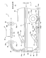
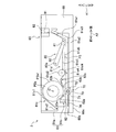
- FIG. 1 is a plan view of the paper feed unit shown in FIG. 1 in a state in which a medium is not accommodated. It is a side view which shows the internal structure of the paper feed unit, and is the state where the 2nd paper feed tray is half-mounted with respect to the housing, and the pinion gear starts to mesh with a rack gear.
- the printer 1 in which the paper feed unit 3 according to the embodiment of the present invention is adopted will be described.
- the printer 1 is installed and used in the state shown in FIG.
- the three directions indicated by arrows in FIG. 1 are the vertical direction A1, the front-rear direction A2, and the left-right direction A3.
- the three directions shown in FIG. 1 are the same in the other drawings.
- the printer 1 is formed in a substantially rectangular parallelepiped shape, and has a printer main body 2 and an additional paper feed unit 3 mounted on the lower part of the printer main body 2.
- the printer main body 2 has a housing 11.
- An opening 12 is formed at substantially the center of the front wall 11a of the housing 11.
- the first paper feed tray 15 and the paper output tray 16 are provided in two upper and lower stages.
- the first paper feed tray 15 is configured to be removable from the opening 12 in the front-rear direction A2, that is, to be detachable from the housing 11.
- the cut sheet P1 of a desired size (for example, A4 size) is placed on the first paper feed tray 15.
- the printer main body 2 can be connected to an external device such as a personal computer (hereinafter referred to as a PC). Then, the recording operation is executed based on the recording command from the PC. In addition, various functions are also executed by the operation of operation buttons by the user.
- a PC personal computer
- the front wall 11a of the housing 11 has an opening / closing cover 4 on the right side thereof.
- the opening / closing cover 4 is configured to be rotatable around the rotation axis (not shown) along the left-right direction A3 at the lower end portion thereof.
- the printer main body 2 includes a first feeding unit 20, a transport roller pair 35, a recording unit 40, a tank unit 18, a paper ejection roller pair 36, and a first ASF (Auto). It includes a Sheet Feed) motor 20M (see FIG. 4), an LF (Line Feed) motor 35M (see FIG. 4), and a control unit 5 (see FIG. 4).
- the first feeding unit 20 feeds the paper P1 placed on the first paper feed tray 15 to the transport path 25.
- the transport roller pair 35 conveys the paper P1 fed by the first feeding unit 20 and the medium P2 fed from the paper feed unit 3 via the branch path 25a to the recording unit 40.
- the recording unit 40 has, for example, an inkjet recording system, and records an image on the paper P1 and the medium P2 conveyed by the transfer roller pair 35.
- the paper ejection roller pair 36 ejects the paper P1 and the medium P2 recorded by the recording unit 40 to the paper ejection tray 16.
- the tank unit 18 has four tanks 18a to 18d. These four tanks 18a to 18d are provided on the downstream side of the printer main body 2 in the transport direction and on the right side portion in FIG. 3, and are arranged side by side in the left-right direction (scanning direction) A3. Black, yellow, cyan, and magenta inks are stored in the four tanks 18a to 18d in order from the one located on the right side. That is, black ink is stored in the rightmost tank 18a, and color ink is stored in the other three tanks 18b to 18d. Then, the inks of these four colors stored in the four tanks 18a to 18d are supplied to the inkjet head 41 (described later) via four tubes or the like (not shown).
- the first feeding unit 20 is provided on the upper side of the first paper feed tray 15.
- the first feeding unit 20 has a first paper feed roller 21 and a first arm 22.
- the first paper feed roller 21 is pivotally supported at the tip of the first arm 22.
- the first arm 22 is rotatably supported by the support shaft 22a and is urged by a spring or the like so that the first paper feed roller 21 is rotated downward so as to come into contact with the first paper feed tray 15. .
- the first arm 22 is configured to be retractable upward when the first paper feed tray 15 is attached / detached.
- the first paper feed roller 21 rotates by transmitting the power of the first ASF motor 20M via a transmission mechanism (not shown), and the paper P1 loaded in the first paper feed tray 15 is supplied to the transport path 25. Will be sent.
- the first paper feed tray 15 has an inclined wall portion 15a.
- the inclined wall portion 15a guides the paper P1 to the transport path 25 when the paper P1 placed on the first paper feed tray 15 is fed by the first paper feed roller 21.
- the transport path 25 is configured in the housing 11, and as shown in FIG. 2, is bent upward from the rear end of the first paper feed tray 15 and toward the front side of the printer 1.
- the paper P1 fed from the first paper feed tray 15 is guided by the transport path 25 to make a U-turn from the bottom to the top and reaches the recording unit 40.
- a branch path 25a is connected to the transport path 25.
- the branch path 25a is also configured in the housing 11, extends in the vertical direction A1 behind the first paper feed tray 15, and is connected to the transport path 25.
- the medium P2 fed from the paper feed unit 3 is guided from the branch path 25a to the transfer path 25, and is guided from the lower side to the front by the transfer path 25 to reach the recording unit 40.
- the transport roller pair 35 has a transport roller 35a arranged on the lower side and a pinch roller 35b arranged on the upper side.
- the transfer roller 35a rotates by transmitting the power of the LF motor 35M via a transmission mechanism (not shown).
- the pinch roller 35b rotates with the rotation of the transport roller 35a.
- the transport roller 35a and the pinch roller 35b cooperate with each other to sandwich the paper P1 and the medium P2 from the vertical direction A1 and transport the paper P1 and the medium P2 to the recording unit 40.
- the paper ejection roller pair 36 has a paper ejection roller 36a arranged on the lower side and a spur roller 36b arranged on the upper side.
- the paper ejection roller 36a rotates by transmitting the power of the LF motor 35M via a transmission mechanism (not shown).
- the spur roller 36b rotates with the rotation of the paper ejection roller 36a.
- the paper ejection roller 36a and the spur roller 36b cooperate with each other to sandwich the paper P1 and the medium P2 from the vertical direction A1 and convey the paper P1 and the medium P2 to the paper ejection tray 16.
- the recording unit 40 includes an inkjet head 41, a head moving mechanism 50, and a platen 6.
- the head moving mechanism 50 includes a carriage 51.
- the carriage 51 reciprocates in the scanning direction (the left-right direction A3, which is orthogonal to the transport direction of the paper P1 and the medium P2).
- the inkjet head 41 is supported by the carriage 51.
- the lower surface of the inkjet head 41 is an ejection surface 41b formed with a plurality of ejection ports 41a for ejecting ink to the paper P1 and the medium P2 conveyed below the inkjet head 41.
- the plurality of discharge ports 41a are arranged so that four discharge port rows arranged along the transport direction are formed in the scanning direction.
- black ink is discharged from the discharge port 41a belonging to the rightmost discharge port row in FIG. 3
- color ink (magenta, cyan) is discharged from the discharge port 41a belonging to the other three rows of discharge port rows.
- Yellow is discharged.
- the inkjet head 41 ejects ink of each color as minute ink droplets from the ejection port 41a under the control of the control unit 5 based on the recording command.
- the inkjet head 41 is integrally provided with a tube joint 44. Then, the inkjet head 41 and the tank unit 18 are connected via four flexible tubes (not shown) connected to the tube joint 44, and ink of each color is supplied to the inkjet head 41.
- a platen 6 that supports the paper P1 and the medium P2 conveyed by the transfer roller pair 35 is arranged below the inkjet head 41.
- the platen 6 is arranged in a portion of the reciprocating movement range of the carriage 51 through which the paper P1 and the medium P2 pass. Since the width of the platen 6 is sufficiently larger than the maximum width of the paper P1 and the medium P2 that can be conveyed, the paper P1 and the medium P2 conveyed through the transport path 25 always pass on the platen 6.
- the head moving mechanism 50 includes a pair of guide rails 52 and a belt transmission mechanism 53.
- the pair of guide rails 52 are arranged apart from each other in the front-rear direction A2 and extend parallel to each other in the left-right direction A3.
- the carriage 51 is arranged so as to straddle the pair of guide rails 52, and is reciprocated on the pair of guide rails 52 along the left-right direction A3.
- the belt transmission mechanism 53 includes two pulleys 54 and 55, an endless timing belt 56 partially fixed to the carriage 51, and a carriage motor 50M.
- the two pulleys 54 and 55 are arranged apart from each other in the left-right direction A3, and the timing belt 56 is bridged.
- the pulley 54 is connected to the drive shaft of the carriage motor 50M, and when the carriage motor 50M is driven, the timing belt 56 travels and the inkjet head 41 moves in the scanning direction together with the carriage 51.
- the inkjet head 41 ejects ink of each color from the ejection port 41a under the control of the control unit 5 based on the recording command. That is, when the carriage 51 reciprocates in the left-right direction A3, the inkjet head 41 is scanned against the paper P1 and the medium P2, and ink of each color is ejected from the ejection port 41a to move on the platen 6. An image is recorded on the conveyed paper P1 and medium P2.
- a linear encoder (not shown) having a large number of translucent portions (slits) arranged at intervals in the scanning direction is provided in the printer 1.
- the carriage 51 is provided with a transmission type position detection sensor (not shown) having a light emitting element and a light receiving element. Then, the printer 1 can recognize the current position of the carriage 51 with respect to the scanning direction from the count value of the translucent portion of the linear encoder detected by the position detection sensor while the carriage 51 is moving. Rotational drive is controlled.
- the control unit 5 includes a CPU (Central Processing Unit), a ROM (Read Only Memory), a RAM (Random Access Memory), an ASIC (Application Specific Integrated Circuit), and the like, and these cooperate with each other.
- 1st ASF motor 20M, 2nd ASF motor 80M (described later), LF motor 35M, carriage motor 50M, inkjet head 41, cutting motor 90M (described later) and the like are controlled.
- the control unit 5 controls the inkjet head 41, the first ASF motor 20M, the LF motor 35M, the carriage motor 50M, and the like based on the recording command transmitted from the PC, and causes the paper P1 to record an image or the like.
- control unit 5 controls the inkjet head 41, the second ASF motor 80M, the LF motor 35M, the carriage motor 50M, the cutting motor 90M, etc. based on the recording command transmitted from the PC, and displays an image or the like on the medium P2. To record.
- the control unit 5 of the present embodiment has one CPU and one ASIC, but the control unit 5 includes only one ASIC, and the one ASIC collectively performs necessary processing. Or, a plurality of ASICs may be included, and the plurality of ASICs may share the necessary processing.
- the paper feed unit 3 includes a housing 60, a second paper feed tray 61, a pullback mechanism 70, a second feed unit 80, and a cutting mechanism. Includes 90 and.
- the paper feed unit 3 can rotatably accommodate the winding body P2a described later.
- the housing 60 has a rectangular parallelepiped shape, and is configured to be removable from the lower part of the printer main body 2.
- An opening 60b is formed at substantially the center of the front wall 60a of the housing 60.
- the housing 60 supports the second paper feed tray 61.
- the second paper feed tray 61 is configured to be removable from the opening 60b in the front-rear direction A2 (orthogonal direction), that is, to be detachable from the housing 60.
- the second paper feed tray 61 has a tray main body 61a, a support base 61b for supporting the winding body P2a of the medium P2, and a transport guide 61d.
- the support base 61b and the transport guide 61d are configured to be removable from the tray body 61a.
- the tray body 61a has a rectangular planar shape.
- the tray body 61a has a flat surface size capable of accommodating, for example, A4 size single-cut paper in a state where the support base 61b and the transport guide 61d are removed. Further, as shown in FIG.
- the tray body 61a has a slanted wall portion 61a1 at the rear end portion.
- the inclined wall portion 61a1 guides the medium P2 fed by the second paper feed roller 81 toward the branch path 25a.
- a pressing portion 61c that presses the winding body P2a toward the support base 61b is provided.
- the pressing portion 61c has a plate-shaped member 61c1 bent in a dogleg shape. The front end of the plate-shaped member 61c1 is rotatably supported by the tray body 61a about the rotation axis 61c2.
- the pressing portion 61c presses the winding body P2a toward the support base 61b by rotating the plate-shaped member 61c1 around the rotation axis 61c2 by its own weight. Therefore, even if the weight of the winding body P2a decreases as the medium P2 decreases, slipping between the roller 71 and the winding body P2a, which will be described later, is unlikely to occur. Therefore, the winding body P2a can be rotated by the roller 71.
- the plate-shaped member 61c1 of the pressing portion 61c may press the winding body P2a by the urging force of the urging member such as a spring.
- the medium P2 is paper like the paper P1, but may be cloth or the like.
- the transport guide 61d has a plate-shaped guide member 61d1 and a roller 61d2.
- the guide member 61d1 has a long substantially rectangular planar shape in the left-right direction A3, a notch portion 61d3 is formed in the rear center, and a notch portion 61d4 is formed in the front.
- the cutout portion 61d3 is formed so that the tip portions of the second paper feed roller 81 and the second arm 82, which will be described later, can be moved in and out by the rotation of the second arm 82.
- a long roller 61d2 is arranged in the cutout portion 61d4 in the left-right direction A3.
- Both ends of the roller 61d2 in the left-right direction A3 are rotatably supported by the guide member 61d1. Further, a long roller 61a4 is rotatably supported on the tray body 61a in the left-right direction A3. The rollers 61a4 are arranged at positions facing the rollers 61d2 in the vertical direction A1. As a result, the medium P2 unwound from the winding body P2a can be sandwiched between these two rollers 61a4 and 61d2.
- the rollers 61d2 are manually rotated counterclockwise in FIG.
- the desired position referred to here is, for example, a position where the second paper feed tray 61 can be in contact with the second paper feed roller 81 or the tray body 61a in a fully mounted state where the second paper feed tray 61 is completely mounted on the housing 60. It is near the rear end in FIG.
- the support base 61b is arranged between the center and the front end of the tray main body 61a in the front-rear direction A2.
- the support base 61b has a base body 62 having a substantially rectangular parallelepiped shape that is long in the left-right direction A3, and a plurality of rollers 63a to 63c.
- the base body 62 is formed with two inclined surfaces 62a and 62b on the upper surface thereof with the center of the front-rear direction A2 interposed therebetween. Of the two inclined surfaces 62a and 62b, the inclined surface 62a is arranged in the front and the inclined surface 62b is arranged in the rear.
- These two inclined surfaces 62a and 62b are configured to incline downward as they approach each other.
- Eight rollers 63a are arranged at the rear end of the inclined surface 62a along the left-right direction A3.
- Eight rollers 63b are arranged at the front end of the slope 62b along the left-right direction A3.
- Eight rollers 63c are arranged at the rear end of the slope 62b along the left-right direction A3.
- the plurality of rollers 63a and 63b come into contact with the lower portion of the outer peripheral surface P2a1 of the winding body P2a of the medium P2, and support the winding body P2a from below.
- the plurality of rollers 63c guide the medium P2 unwound from the winding body P2a.
- the base body 62 is formed with a groove 62c that opens upward. As shown in FIG. 6, the groove 62c is arranged at the center of the base body 62 in the front-rear direction A2 and between the two inclined surfaces 62a and 62b. Further, a penetrating portion 62d is formed in the center of the base body 62 in the left-right direction A3.
- ⁇ Pullback mechanism (rotation mechanism) 70> The pullback mechanism 70 moves the second paper feed tray 61 in a direction orthogonal to the rotation axis C of the winder P2a and removes the second paper feed tray 61 from the housing 60. The medium P2 unwound from P2a is pulled back.
- the pullback mechanism 70 has a rotation mechanism that rotates so as to pull back the medium P2 unwound from the winding body P2a in conjunction with the operation of removing the second paper feed tray 61. In the present embodiment, since the rotation mechanism itself is the pullback mechanism 70, the rotation mechanism will be described with the same reference numerals as the pullback mechanism 70.
- the rotation mechanism 70 includes a roller 71, a power transmission unit 72, a pinion gear 73, and a rack gear 74 that can mesh with the pinion gear 73.
- the roller 71, the power transmission unit 72, and the pinion gear 73 are arranged side by side in the left-right direction A3 at positions facing the penetrating portion 62d. Further, these rollers 71, the power transmission unit 72, and the pinion gear 73 are supported by the bottom portion 61a2 of the tray body 61a so as to be rotatable and movable in the vertical direction A1. As shown in FIG.
- the roller 71 has a diameter larger than that of the pinion gear 73, and is formed in a size that allows it to move up and down in the penetrating portion 62d.
- the roller 71 moves between a separation position (see FIG. 5) that separates the winding body P2a downward from the outer peripheral surface P2a1 and an abutting position (see FIG. 8) that abuts on the outer peripheral surface P2a1 of the winding body P2a. It is supported as much as possible.
- the power transmission unit 72 is a known one-way clutch, and transmits the rotational force in one direction of the pinion gear 73 to the roller 71.
- the power transmission unit 72 in the present embodiment transmits the rotational force when the pinion gear 73 rotates counterclockwise to the roller 71, and does not transmit the rotational force when the pinion gear 73 rotates clockwise to the roller 71. It is configured in.
- the pinion gear 73 is configured to be rotatable by meshing with the rack gear 74.
- the rack gear 74 is arranged on the bottom 60c of the housing 60 and closer to the front than the center of the bottom 60c in the front-rear direction A2.
- the rack gear 74 extends along the front-rear direction A2 and is configured to be able to mesh with the pinion gear 73. That is, as shown in FIGS. 5 and 6, the rack gear 74 is arranged in front of the pinion gear 73 in a fully mounted state in which the second paper feed tray 61 is fully mounted on the housing 60. It is arranged at a position where it can mesh with the lower portion of the pinion gear 73 in the semi-mounted state without meshing with the pinion gear 73.
- the semi-mounted state refers to the state of the second paper feed tray 61 until the second paper feed tray 61 is moved forward from the fully mounted state and the second paper feed tray 61 is removed from the housing 60. Further, the rack gear 74 meshes with the pinion gear 73 when the second paper feed tray 61 is moved forward from the fully mounted state, so that the pinion gear 73 is rotated counterclockwise in FIG. 5 with respect to the housing 60. When the second paper feed tray 61 in the semi-mounted state is moved rearward, it meshes with the pinion gear 73 to rotate the pinion gear 73 clockwise in FIG.
- the rack gear 74 is arranged at a position where the roller 71 can be positioned from the separation position to the contact position when meshing with the pinion gear 73.
- the lower surface of the tray body 61a has a groove extending along the front-rear direction A2 so as not to come into contact with the rack gear 74 when the second paper feed tray 61 is mounted on the housing 60. 61a3 is formed.
- the second feeding unit 80 is provided on the upper side of the second paper feed tray 61.
- the second feeding unit 80 has a second paper feed roller 81 and a second arm 82.
- the second paper feed roller 81 is pivotally supported at the tip of the second arm 82.
- the second arm 82 is rotatably supported by the support shaft 82a and is urged by a spring or the like so that the second paper feed roller 81 is rotated downward so as to come into contact with the second paper feed tray 61. ..
- the second arm 82 is configured to be retractable to an upper retracted position (see FIG. 7) when the second paper feed tray 61 is attached / detached.
- the power of the second ASF motor 80M is transmitted to the second paper feed roller 81 via a transmission mechanism (not shown) to rotate the second paper feed roller 81, and the second paper feed roller 81 is unwound from the winding body P2a housed in the second paper feed tray 61.
- the medium P2 is fed to the branch path 25a via the cutting mechanism 90.
- the cutting mechanism 90 is installed in the upper rear portion of the housing 60.
- the cutting mechanism 90 is a known cutting mechanism that extends long along the left-right direction A3 and can cut the medium P2 along the left-right direction A3.
- the cutting mechanism 90 includes a guide portion 92 for defining a transport path 91 passing through the medium P2 fed by the second paper feed roller 81, a cutter (not shown), and a cutting motor 90M (not shown) for driving the cutter. (See FIG. 4).
- the cutter is configured to be movable along the left-right direction A3 and cuts the medium P2 in the transport path 91.
- the cutting mechanism 90 cuts the medium P2 fed by the second feeding unit 80 at a desired position under the control of the control unit 5. Therefore, the tip of the cut medium P2 is arranged at a position above the tip of the second paper feed tray 61 (rear end in FIG. 5). In the present embodiment, the tip of the cut medium P2 is located in the transport path 91. In the present embodiment, the cutting mechanism 90 is provided in the housing 60, but it may be provided in the printer main body 2.
- the winding body P2a is rotated by the rotation mechanism 70, and the medium P2 Is rewound and the tip of the medium P2 moves.
- the second arm 82 has moved to the retracted position.
- the tip of the medium P2 is arranged between the rear end of the transport guide 61d and the tray main body 61a as shown in FIG. That is, the rotating mechanism 70 pulls out the second paper feed tray 61 from the fully mounted state to the position where the pinion gear 73 is located in front of the rack gear 74 (the position where the meshing between the pinion gear 73 and the rack gear 74 ends), so that the medium P2
- the winding body P2a is configured to rotate so that the tip of the paper feed roller 81 moves from the transport path 91 to the front of the contact point between the second paper feed roller 81 and the bottom portion 61a2 of the tray body 61a.
- the tip of the medium P2 is the inclined wall portion 61a1 of the tray body 61a. It suffices if it is possible to rotate the winding body P2a to a position located below the upper end of the winding body P2a.
- the user moves the second paper feed tray 61 rearward and reattaches it to the housing 60.
- the pinion gear 73 and the rack gear 74 mesh with each other and the pinion gear 73 rotates clockwise in FIG. 5, but the rotational force of the pinion gear 73 is not transmitted to the roller 71 by the power transmission unit 72, and the roller 71 is a wound body.
- the tip of the medium P2 does not move when the second paper feed tray 61 is mounted on the housing 60, and is located in the tray main body 61a, that is, below the upper end of the inclined wall portion 61a1. ..
- the tip of the medium P2 is arranged in the tray body 61a, so that the second paper feed tray 61 At the time of mounting, the tip of the medium P2 does not come into contact with the components of the second feeding unit 80 and the housing 60. Therefore, the second paper feed tray 61 can be mounted on the housing 60 without bending the tip of the medium P2.
- the paper feed unit 3 of the present embodiment when the second paper feed tray 61 is removed from the housing 60, a part of the medium P2 unwound from the winding body P2a is wound. It is rewound to the body P2a, and the tip of the medium P2 is pulled back from the transport path 91 into the second paper feed tray 61. Therefore, when the second paper feed tray 61 is reattached to the housing 60, the tip of the medium P2 is less likely to come into contact with the housing 60 or the like, and is less likely to bend.
- the tip of the medium P2 is less likely to bend, so that a paper feed failure such as a jam of the medium P2 occurs when the medium P2 is fed. It becomes possible to suppress.
- the rotation mechanism 70 includes the roller 71, the pinion gear 73, and the rack gear 74, the roller 71 is rotated when the second paper feed tray 61 is removed from the housing 60 with a relatively simple configuration. It becomes possible to rotate the winding body P2a.
- the second paper feed tray 61 has the tray body 61a and the support base 61b and the roller 71 is supported by the tray body 61a, when the second paper feed tray 61 is removed from the housing 60, The winding body P2a of the medium P2 mounted on the support base 61b can be rotated by the roller 71.
- the tray body 61a is configured to accommodate the cut sheet paper with the support base 61b removed, it is also possible to feed the cut sheet paper.
- the roller 71 can also be rotated by a desired number, and the winding body P2a can be rotated by a required amount.
- the roller 71 is arranged at a separated position when the rack gear 74 and the pinion gear 73 are not meshed with each other, and when the rack gear 74 and the pinion gear 73 are engaged with each other, the roller 71 is positioned at the contact position from the separated position.
- the rollers 71 are arranged at the separated positions, so that the transport load by the rollers 71 does not occur when the medium P2 is fed.
- the rotation mechanism 70 Since the rotation mechanism 70 has the power transmission unit 72, it is possible to prevent the tip of the medium P2 from moving and coming into contact with the housing 60 or the like when the second paper feed tray 61 is mounted. It becomes.
- the tip of the medium P2 when the second paper feed tray 61 is removed from the housing 60 is the tip of the second paper feed tray 61 when the second paper feed tray 61 is mounted on the housing 60.
- the winding body P2a is rotated so as to be arranged below the upper end of (the rear end portion in FIG. 5). As a result, when the second paper feed tray 61 is reattached to the housing 60, the tip of the medium P2 is less likely to come into contact with the housing 60 or the like.
- the present invention is not limited to the above-described embodiment, and various modifications can be made as long as it is described in the claims.
- the above-mentioned paper feed unit 3 is an extension unit that can be attached to and detached from the printer main body 2, but may be integrally fixed to the printer main body 2.
- the housing 11 and the first paper feed tray 15 of the printer main body 2 may be provided with a rotation mechanism similar to the rotation mechanism 70, and the printer main body 2 itself may be provided with a paper feed unit. Also in this case, the same effect as that of the above-described embodiment can be obtained.
- the rotation mechanism 70 has a roller 71, a pinion gear 73, and a rack gear 74.
- the medium P2 is wound. Any configuration may be used as long as the winding body P2a can be rotated so as to be rewound to the body P2ab, and is not particularly limited.
- the outer peripheral surface of the roller that comes into contact with the outer peripheral surface P2a1 of the winding body P2a below comes into contact with the housing 60, so that the roller rotates and winds.
- the body P2a may be rotated. In this way, it is not necessary to have the pinion gear 73 and the rack gear 74.
- the second paper feed tray 61 does not have to have the support base 61b.
- a shaft portion may be provided at the center of the winding body P2a of the medium P2, and the shaft portion may be rotatably supported by the tray body 61a.
- the support base 61b may be fixed to the tray main body 61a.
- the pressing portion 61c may not be provided on the tray main body 61a. Further, the pressing portion 61c may be provided in the housing 60, and the same effect as described above can be obtained.
- the pinion gear 73 may have a diameter of the roller 71 or more. In this case, it is desirable to arrange the pinion gear 73 at a position where it does not come into contact with the winding body P2a. Further, the roller 71 may be positioned only at the contact position. In this case, it is desirable that the pinion gear 73 and the rack gear 74 do not mesh with each other when the second paper feed tray 61 is completely mounted on the housing 60. In this way, even if the winding body P2a and the roller 71 are in contact with each other, the roller 71 can be rotated by the rotation of the winding body P2a, and the transport load by the roller 71 is suppressed when the medium P2 is fed. be able to.
- the rotation mechanism 70 does not have to have the power transmission unit 72.
- the medium P2 is wound up when the second paper feed tray 61 is removed from the housing 60 until the tip of the medium P2 comes into contact with the housing 60 or the like. This makes it possible to prevent the tip of the medium P2 from coming into contact with the housing 60 or the like when the second paper feed tray 61 is mounted on the housing 60.
- the tip of the medium P2 will be the second paper feed.
- the tray 61 may be arranged slightly above the upper end of the tip end portion of the second paper feed tray 61 when the tray 61 is mounted on the housing 60. Also in this case, when the second paper feed tray 61 is reattached to the housing 60, the tip of the medium P2 is less likely to come into contact with the housing 60 or the like, and is less likely to be bent.
- the present invention is not limited to this. It can be applied to the entire paper feed unit capable of rotatably accommodating the wound body P2a of the medium P2.
- Paper feed unit 60 Housing 61 Second paper feed tray (paper feed tray) 61a Tray body 61b Support base 61c Pressing part 70 Pullback mechanism (rotation mechanism) 71 Roller 72 Power transmission unit 73 Pinion gear 74 Rack gear
Abstract
筐体に対する給紙トレイの着脱動作により媒体の給紙不良が生じるのを抑制する。給紙ユニット3は、媒体P2がロール状に巻回された巻回体P2aを回転可能に収容可能な第2給紙トレイ61と、第2給紙トレイ61を着脱可能に支持する筐体60と、引き戻し機構70とを含む。引き戻し機構70は、第2給紙トレイ61を前方に移動させて筐体60から第2給紙トレイ61を取り外す動作に連動して、巻回体P2aから巻き出された媒体P2を引き戻す。
Description
本発明は、媒体を収容可能な給紙トレイが筐体に着脱可能に設けられた給紙ユニットに関する。
特許文献1には、画像処理装置の装置本体に引出自在に装着され、ロール状に巻かれた媒体の巻回体を収容可能な2つの給紙トレイについて記載されている。これら給紙トレイは、上下二段に配置されており、それぞれに、巻回体から巻き出された媒体を搬送する送り出しローラと、送り出しローラにより搬送される媒体を案内する給紙通路と、給紙通路を通る媒体を切断可能なカッターとが設けられている。
上記特許文献1に記載の給紙トレイには、送り出しローラに加えてカッターまで設けられているため、給紙トレイ自体の構成が複雑な構成となる。そこで本発明者は、例えば、画像処理装置の装置本体に設けられた給紙トレイを装着するための筐体又は装置本体に着脱可能な増設用の筐体であって給紙トレイを装着するための筐体側に、送り出しローラやカッターを設けて、給紙トレイ自体の構成を簡略化することを検討したところ、以下の課題を知見した。
筐体側にカッターなどの切断機構を設けた場合、切断機構で切断された媒体の先端は給紙トレイよりも上方に飛び出た位置に配置される。この状態で給紙トレイを移動させて一旦筐体から取り外した後、再度、給紙トレイを筐体に装着した場合、媒体の先端が筐体に設けられた構成要素(例えば、給紙ローラなど)に接触し、媒体が折れ曲がることがある。このように給紙トレイの着脱動作により媒体が折れ曲がると、装着後に給紙不良が発生する問題がある。
本発明の目的は、筐体に対する給紙トレイの着脱動作により媒体の給紙不良が生じるのを抑制することが可能な給紙ユニットを提供することである。
本発明の給紙ユニットは、媒体がロール状に巻回された巻回体を回転可能に収容可能な給紙トレイと、前記給紙トレイを着脱可能に支持する筐体とを備えた給紙ユニットにおいて、前記巻回体の回転軸心と直交する方向に前記給紙トレイを移動させて前記筐体から前記給紙トレイを取り外す動作に連動して、前記巻回体から巻き出された媒体を引き戻す引き戻し機構を備えている。
本発明の給紙ユニットによると、筐体から給紙トレイを取り外す際に、巻回体から巻き出された媒体が引き戻される。このため、給紙トレイを筐体に再度装着するときに、媒体の先端が筐体などに接触しにくくなり、折れ曲がりにくくなる。したがって、筐体に対する給紙トレイの着脱動作により媒体の給紙不良が生じるのを抑制することが可能となる。
以下、本発明の一実施形態に係る給紙ユニット3が採用されたプリンタ1について説明する。プリンタ1は、図1に示す状態に設置されて使用される。本実施形態において、図1に矢印を付して示す3つの方向が、上下方向A1、前後方向A2、及び左右方向A3である。図1に示す3つの方向は、他の図面においても同様である。
<プリンタ1の概要>
図1に示すように、プリンタ1は、概ね直方体に形成されており、プリンタ本体2と、プリンタ本体2の下部に装着された増設用の給紙ユニット3とを有する。プリンタ本体2は、筐体11を有する。筐体11の前壁11aの略中央には、開口12が形成されている。第1給紙トレイ15及び排紙トレイ16が、上下2段に設けられている。第1給紙トレイ15は、開口12から前後方向A2に挿抜可能、すなわち、筐体11から着脱可能に構成されている。所望のサイズ(例えば、A4サイズ)の単票用紙P1が第1給紙トレイ15に載置される。プリンタ本体2は、パーソナルコンピュータ(以下PCと称する)などの外部機器と接続可能である。そして、PCからの記録指令に基づいて記録動作を実行する。また、ユーザによる操作ボタンの操作によっても各種機能を実行する。
図1に示すように、プリンタ1は、概ね直方体に形成されており、プリンタ本体2と、プリンタ本体2の下部に装着された増設用の給紙ユニット3とを有する。プリンタ本体2は、筐体11を有する。筐体11の前壁11aの略中央には、開口12が形成されている。第1給紙トレイ15及び排紙トレイ16が、上下2段に設けられている。第1給紙トレイ15は、開口12から前後方向A2に挿抜可能、すなわち、筐体11から着脱可能に構成されている。所望のサイズ(例えば、A4サイズ)の単票用紙P1が第1給紙トレイ15に載置される。プリンタ本体2は、パーソナルコンピュータ(以下PCと称する)などの外部機器と接続可能である。そして、PCからの記録指令に基づいて記録動作を実行する。また、ユーザによる操作ボタンの操作によっても各種機能を実行する。
また、筐体11の前壁11aは、図1に示すように、その右方部分に開閉カバー4を有する。開閉カバー4は、その下端部において、左右方向A3に沿う回転軸心(不図示)を回転中心として回動可能に構成されている。
<プリンタ本体2の内部構造>
次に、プリンタ本体2の内部構造について説明する。図2及び図3に示すように、プリンタ本体2は、第1給送部20と、搬送ローラ対35と、記録部40と、タンクユニット18と、排紙ローラ対36と、第1ASF(Auto Sheet Feed)モータ20M(図4参照)と、LF(Line Feed)モータ35M(図4参照)と、制御部5(図4参照)とを含む。
次に、プリンタ本体2の内部構造について説明する。図2及び図3に示すように、プリンタ本体2は、第1給送部20と、搬送ローラ対35と、記録部40と、タンクユニット18と、排紙ローラ対36と、第1ASF(Auto Sheet Feed)モータ20M(図4参照)と、LF(Line Feed)モータ35M(図4参照)と、制御部5(図4参照)とを含む。
第1給送部20は、第1給紙トレイ15に載置される用紙P1を搬送路25へ給送する。搬送ローラ対35は、第1給送部20によって給紙された用紙P1、及び、給紙ユニット3から分岐路25aを介して給紙された媒体P2を記録部40に搬送する。記録部40は、例えば、インクジェット記録方式の構成を有し、搬送ローラ対35によって搬送された用紙P1及び媒体P2に画像を記録する。排紙ローラ対36は、記録部40によって記録された用紙P1及び媒体P2を排紙トレイ16に排紙する。
<タンクユニット18>
タンクユニット18は、図3に示すように、4つのタンク18a~18dを有している。これら4つのタンク18a~18dは、プリンタ本体2の搬送方向の下流側且つ図3中右側の部分に設けられ、左右方向(走査方向)A3に並んで配置されている。4つのタンク18a~18dには、右側に位置するものから順に、ブラック、イエロー、シアン、マゼンタのインクが貯留されている。つまり、最も右側のタンク18aには、ブラックインクが貯留されており、その他の3つのタンク18b~18dには、カラーインクが貯留されている。そして、4つのタンク18a~18dに貯留されたこれら4色のインクが4本のチューブ等(不図示)を介してインクジェットヘッド41(後述する)に供給される。
タンクユニット18は、図3に示すように、4つのタンク18a~18dを有している。これら4つのタンク18a~18dは、プリンタ本体2の搬送方向の下流側且つ図3中右側の部分に設けられ、左右方向(走査方向)A3に並んで配置されている。4つのタンク18a~18dには、右側に位置するものから順に、ブラック、イエロー、シアン、マゼンタのインクが貯留されている。つまり、最も右側のタンク18aには、ブラックインクが貯留されており、その他の3つのタンク18b~18dには、カラーインクが貯留されている。そして、4つのタンク18a~18dに貯留されたこれら4色のインクが4本のチューブ等(不図示)を介してインクジェットヘッド41(後述する)に供給される。
<第1給送部20>
図2に示すように、第1給送部20が第1給紙トレイ15の上側に設けられている。第1給送部20は、第1給紙ローラ21と第1アーム22を有する。第1給紙ローラ21は、第1アーム22の先端に軸支されている。第1アーム22は、支軸22aに回動自在に支持され、バネなどにより付勢されて第1給紙ローラ21が第1給紙トレイ15に接触するように下側へ回動されている。また、第1アーム22は、第1給紙トレイ15の着脱する際に上方へ退避可能に構成されている。第1給紙ローラ21は、伝達機構(不図示)を介して第1ASFモータ20Mの動力が伝達されて回転し、第1給紙トレイ15内に積載された用紙P1が、搬送路25へ給送される。
図2に示すように、第1給送部20が第1給紙トレイ15の上側に設けられている。第1給送部20は、第1給紙ローラ21と第1アーム22を有する。第1給紙ローラ21は、第1アーム22の先端に軸支されている。第1アーム22は、支軸22aに回動自在に支持され、バネなどにより付勢されて第1給紙ローラ21が第1給紙トレイ15に接触するように下側へ回動されている。また、第1アーム22は、第1給紙トレイ15の着脱する際に上方へ退避可能に構成されている。第1給紙ローラ21は、伝達機構(不図示)を介して第1ASFモータ20Mの動力が伝達されて回転し、第1給紙トレイ15内に積載された用紙P1が、搬送路25へ給送される。
<第1給紙トレイ15>
図2に示すように、第1給紙トレイ15は、斜壁部15aを有する。斜壁部15aは、第1給紙トレイ15に載置される用紙P1が第1給紙ローラ21によって給送されるときに、用紙P1を搬送路25に案内する。
図2に示すように、第1給紙トレイ15は、斜壁部15aを有する。斜壁部15aは、第1給紙トレイ15に載置される用紙P1が第1給紙ローラ21によって給送されるときに、用紙P1を搬送路25に案内する。
<搬送路25>
搬送路25は、筐体11内に構成されており、図2に示すように、第1給紙トレイ15の後側の端部から上方且つプリンタ1の前側へ曲がっている。第1給紙トレイ15から給送された用紙P1は、搬送路25により下方から上方へUターンするように案内されて記録部40に至る。
搬送路25は、筐体11内に構成されており、図2に示すように、第1給紙トレイ15の後側の端部から上方且つプリンタ1の前側へ曲がっている。第1給紙トレイ15から給送された用紙P1は、搬送路25により下方から上方へUターンするように案内されて記録部40に至る。
<分岐路25a>
搬送路25には、分岐路25aが接続されている。分岐路25aも筐体11内に構成されており、第1給紙トレイ15よりも後方において、上下方向A1に延在しており、搬送路25に接続されている。給紙ユニット3から給送された媒体P2は、分岐路25aから搬送路25へと案内され、搬送路25により下方から前方へと案内されて記録部40に至る。
搬送路25には、分岐路25aが接続されている。分岐路25aも筐体11内に構成されており、第1給紙トレイ15よりも後方において、上下方向A1に延在しており、搬送路25に接続されている。給紙ユニット3から給送された媒体P2は、分岐路25aから搬送路25へと案内され、搬送路25により下方から前方へと案内されて記録部40に至る。
<搬送ローラ対35、及び、排紙ローラ対36>
搬送ローラ対35は、下側に配置された搬送ローラ35aと上側に配置されたピンチローラ35bとを有する。搬送ローラ35aは、伝達機構(不図示)を介してLFモータ35Mの動力が伝達されて回転する。ピンチローラ35bは、搬送ローラ35aの回転に伴って連れ回る。搬送ローラ35aとピンチローラ35bとは、協働して用紙P1及び媒体P2を上下方向A1から挟持し、用紙P1及び媒体P2を記録部40へ搬送する。
搬送ローラ対35は、下側に配置された搬送ローラ35aと上側に配置されたピンチローラ35bとを有する。搬送ローラ35aは、伝達機構(不図示)を介してLFモータ35Mの動力が伝達されて回転する。ピンチローラ35bは、搬送ローラ35aの回転に伴って連れ回る。搬送ローラ35aとピンチローラ35bとは、協働して用紙P1及び媒体P2を上下方向A1から挟持し、用紙P1及び媒体P2を記録部40へ搬送する。
排紙ローラ対36は、下側に配置された排紙ローラ36aと、上側に配置された拍車ローラ36bとを有する。排紙ローラ36aは、伝達機構(不図示)を介してLFモータ35Mの動力が伝達されて回転する。拍車ローラ36bは、排紙ローラ36aの回転に伴って連れ回る。排紙ローラ36aと拍車ローラ36bとは、協働して用紙P1及び媒体P2を上下方向A1から挟持し、用紙P1及び媒体P2を排紙トレイ16に搬送する。
<記録部40>
図2及び図3に示すように、記録部40は、インクジェットヘッド41と、ヘッド移動機構50と、プラテン6とを有する。ヘッド移動機構50は、キャリッジ51を含む。キャリッジ51は、走査方向(左右方向A3であって、用紙P1及び媒体P2の搬送方向と直交する方向)へ往復移動する。インクジェットヘッド41は、キャリッジ51に支持されている。
図2及び図3に示すように、記録部40は、インクジェットヘッド41と、ヘッド移動機構50と、プラテン6とを有する。ヘッド移動機構50は、キャリッジ51を含む。キャリッジ51は、走査方向(左右方向A3であって、用紙P1及び媒体P2の搬送方向と直交する方向)へ往復移動する。インクジェットヘッド41は、キャリッジ51に支持されている。
インクジェットヘッド41の下面は、当該インクジェットヘッド41の下方に搬送された用紙P1及び媒体P2に対してインクを吐出する複数の吐出口41aが形成された吐出面41bである。複数の吐出口41aは、図3に示すように、搬送方向に沿って配列された吐出口列が走査方向に4列形成されるように配置されている。本実施形態において、図3中最も右側の吐出口列に属する吐出口41aからは、ブラックインクが吐出され、他の3列の吐出口列に属する吐出口41aからは、カラーインク(マゼンタ、シアン、イエロー)が吐出される。インクジェットヘッド41は、記録指令に基づく制御部5の制御により、吐出口41aから各色のインクを微小なインク滴として吐出する。
インクジェットヘッド41には、チューブジョイント44が一体的に設けられている。そして、チューブジョイント44に連結された可撓性の4本のチューブ(不図示)を介して、インクジェットヘッド41とタンクユニット18とが接続され、各色のインクがインクジェットヘッド41に供給される。
インクジェットヘッド41の下方には、搬送ローラ対35によって搬送される用紙P1及び媒体P2を支持するプラテン6が配設されている。プラテン6は、キャリッジ51の往復移動範囲のうち、用紙P1及び媒体P2が通過する部分に配設されている。プラテン6の幅は、搬送可能な用紙P1及び媒体P2の最大幅より十分に大きいので、搬送路25を搬送される用紙P1及び媒体P2は常にプラテン6上を通過する。
ヘッド移動機構50は、図3に示すように、一対のガイドレール52、及び、ベルト伝達機構53を含む。一対のガイドレール52は、前後方向A2に離隔して配置され、左右方向A3に互いに平行に延在している。キャリッジ51は、これら一対のガイドレール52を跨ぐように配置され、当該一対のガイドレール52上を左右方向A3に沿って往復移動される。
また、ベルト伝達機構53は、2つのプーリ54,55と、一部がキャリッジ51に固定された無端状のタイミングベルト56と、キャリッジモータ50Mとを含む。2つのプーリ54,55は、左右方向A3に互いに離隔して配置され、タイミングベルト56が架け渡されている。プーリ54は、キャリッジモータ50Mの駆動軸と連結されており、キャリッジモータ50Mが駆動されることで、タイミングベルト56が走行し、キャリッジ51とともにインクジェットヘッド41が走査方向に移動する。
インクジェットヘッド41は、記録指令に基づく制御部5の制御により、吐出口41aから各色のインクを吐出する。つまり、キャリッジ51が左右方向A3へ往復移動することにより、インクジェットヘッド41が用紙P1及び媒体P2に対して走査されると共に、吐出口41aから、各色のインクを吐出することで、プラテン6上を搬送される用紙P1及び媒体P2に画像が記録される。なお、プリンタ1内には、走査方向に間隔を空けて配列された多数の透光部(スリット)を有するリニアエンコーダ(不図示)が設けられている。一方、キャリッジ51には、発光素子と受光素子とを有する透過型の位置検出センサ(不図示)が設けられている。そして、プリンタ1は、キャリッジ51の移動中に位置検出センサが検出したリニアエンコーダの透光部の計数値から、キャリッジ51の走査方向に関する現在位置を認識できるようになっており、キャリッジモータ50Mの回転駆動が制御される。
図4に示すように、制御部5は、CPU(Central Processing Unit)、ROM(Read Only Memory)、RAM(Random Access Memory)、ASIC(Application Specific Integrated Circuit)などを含み、これらが協働して、第1ASFモータ20M、第2ASFモータ80M(後述する)、LFモータ35M、キャリッジモータ50M、インクジェットヘッド41、切断用モータ90M(後述する)等の動作を制御する。例えば、制御部5は、PCから送信された記録指令に基づいて、インクジェットヘッド41、第1ASFモータ20M、LFモータ35M、キャリッジモータ50M等を制御して、用紙P1に画像等を記録させる。また、制御部5は、PCから送信された記録指令に基づいて、インクジェットヘッド41、第2ASFモータ80M、LFモータ35M、キャリッジモータ50M、切断用モータ90M等を制御して、媒体P2に画像等を記録させる。
なお、本実施形態の制御部5では、CPU及びASICを1つずつ有しているが、制御部5は、ASICを1つだけ含み、この1つのASICが必要な処理を一括して行うものであってもよいし、ASICを複数含み、これら複数のASICが必要な処理を分担して行うものであってもよい。
<給紙ユニット3>
給紙ユニット3は、図1、図2、図5及び図6に示すように、筐体60と、第2給紙トレイ61と、引き戻し機構70と、第2給送部80と、切断機構90とを含む。給紙ユニット3は、後述する巻回体P2aを回転可能に収容可能である。筐体60は、図1に示すように、直方体形状を有しており、プリンタ本体2の下部に着脱可能に構成されている。筐体60の前壁60aの略中央には、開口60bが形成されている。筐体60は、第2給紙トレイ61を支持する。第2給紙トレイ61は、開口60bから前後方向A2(直交する方向)に挿抜可能、すなわち、筐体60から着脱可能に構成されている。
給紙ユニット3は、図1、図2、図5及び図6に示すように、筐体60と、第2給紙トレイ61と、引き戻し機構70と、第2給送部80と、切断機構90とを含む。給紙ユニット3は、後述する巻回体P2aを回転可能に収容可能である。筐体60は、図1に示すように、直方体形状を有しており、プリンタ本体2の下部に着脱可能に構成されている。筐体60の前壁60aの略中央には、開口60bが形成されている。筐体60は、第2給紙トレイ61を支持する。第2給紙トレイ61は、開口60bから前後方向A2(直交する方向)に挿抜可能、すなわち、筐体60から着脱可能に構成されている。
<第2給紙トレイ61>
図5及び図6に示すように、第2給紙トレイ61は、トレイ本体61aと、媒体P2の巻回体P2aを支持する支持台61bと、搬送ガイド61dとを有する。支持台61b及び搬送ガイド61dは、トレイ本体61aに対して着脱可能に構成されている。トレイ本体61aは、図6に示すように、矩形平面形状を有している。また、トレイ本体61aは、支持台61b及び搬送ガイド61dを取り外した状態において、例えば、A4サイズの単票用紙を収容可能な平面サイズを有している。また、トレイ本体61aは、図5に示すように、後方端部に斜壁部61a1を有する。斜壁部61a1は、第2給紙ローラ81によって給送される媒体P2を分岐路25aに向かって案内する。トレイ本体61aの前方端部には、巻回体P2aを支持台61bに向けて押圧する押圧部61cが設けられている。押圧部61cは、図5に示すように、くの字に折り曲げられた板状部材61c1を有する。板状部材61c1は、その前端が回転軸心61c2を中心に回動可能にトレイ本体61aに支持されている。これにより、押圧部61cは、板状部材61c1が回転軸心61c2を回転中心として自重で回動することで、巻回体P2aを支持台61bに向けて押圧する。このため、媒体P2の減少に伴って巻回体P2aの自重が小さくなっても、後述のローラ71と巻回体P2aとの間にスリップが生じにくくなる。したがって、ローラ71で巻回体P2aを回転させることができる。なお、押圧部61cの板状部材61c1は、バネなどの付勢部材の付勢力によって巻回体P2aを押圧していてもよい。媒体P2は、用紙P1と同様に紙であるが、布などであってもよい。
図5及び図6に示すように、第2給紙トレイ61は、トレイ本体61aと、媒体P2の巻回体P2aを支持する支持台61bと、搬送ガイド61dとを有する。支持台61b及び搬送ガイド61dは、トレイ本体61aに対して着脱可能に構成されている。トレイ本体61aは、図6に示すように、矩形平面形状を有している。また、トレイ本体61aは、支持台61b及び搬送ガイド61dを取り外した状態において、例えば、A4サイズの単票用紙を収容可能な平面サイズを有している。また、トレイ本体61aは、図5に示すように、後方端部に斜壁部61a1を有する。斜壁部61a1は、第2給紙ローラ81によって給送される媒体P2を分岐路25aに向かって案内する。トレイ本体61aの前方端部には、巻回体P2aを支持台61bに向けて押圧する押圧部61cが設けられている。押圧部61cは、図5に示すように、くの字に折り曲げられた板状部材61c1を有する。板状部材61c1は、その前端が回転軸心61c2を中心に回動可能にトレイ本体61aに支持されている。これにより、押圧部61cは、板状部材61c1が回転軸心61c2を回転中心として自重で回動することで、巻回体P2aを支持台61bに向けて押圧する。このため、媒体P2の減少に伴って巻回体P2aの自重が小さくなっても、後述のローラ71と巻回体P2aとの間にスリップが生じにくくなる。したがって、ローラ71で巻回体P2aを回転させることができる。なお、押圧部61cの板状部材61c1は、バネなどの付勢部材の付勢力によって巻回体P2aを押圧していてもよい。媒体P2は、用紙P1と同様に紙であるが、布などであってもよい。
搬送ガイド61dは、図5及び図6に示すように、板状のガイド部材61d1と、ローラ61d2とを有する。ガイド部材61d1は、図6に示すように、左右方向A3に長尺な略矩形平面形状を有し、後方中央に切り欠き部61d3が形成され、前方に切り欠き部61d4が形成されている。切り欠き部61d3は、後述する第2給紙ローラ81及び第2アーム82の先端部が、第2アーム82の回動により、ちょうど出入り可能に形成されている。切り欠き部61d4には、左右方向A3に長尺なローラ61d2が配置されている。ローラ61d2は、左右方向A3の両端部がガイド部材61d1に回転可能に支持されている。また、トレイ本体61aには、左右方向A3に長尺なローラ61a4が回転可能に支持されている。ローラ61a4は、上下方向A1において、ローラ61d2と対向する位置に配置されている。これにより、巻回体P2aから巻き出された媒体P2をこれら2つのローラ61a4,61d2で挟持することが可能となる。このため、巻回体P2aを支持台61bにセットし、巻回体P2aから巻き出した媒体P2を、2つのローラ61a4,61d2で挟持した状態で、ローラ61d2を手動で図5中反時計回りに回転させることで、媒体P2の先端を所望位置まで送り出してセットしやすくなる。ここでいう、所望位置とは、例えば、第2給紙トレイ61が筐体60に対して完全に装着された完全装着状態において、第2給紙ローラ81と接触可能な位置やトレイ本体61aの図5中後方端近傍である。
支持台61bは、図5及び図6に示すように、前後方向A2において、トレイ本体61aの中央と前端との間に配置されている。支持台61bは、左右方向A3に長尺な略直方体形状の台本体62と、複数のローラ63a~63cとを有している。台本体62は、その上面に前後方向A2の中央を挟んで2つの傾斜面62a,62bが形成されている。2つの傾斜面62a,62bのうち、傾斜面62aは前方に配置されており、傾斜面62bは後方に配置されている。これら2つの傾斜面62a,62bは、互いに近づくに連れて下方に傾斜するように構成されている。ローラ63aは、傾斜面62aの後端部に左右方向A3に沿って8つ配列されている。ローラ63bは、斜面62bの前端部に左右方向A3に沿って8つ配列されている。ローラ63cは、斜面62bの後端部に左右方向A3に沿って8つ配列されている。これら複数のローラ63a,63bは、媒体P2の巻回体P2aの外周面P2a1の下方部分と当接し、巻回体P2aを下方から支持する。複数のローラ63cは、巻回体P2aから巻き出された媒体P2を案内する。これら複数のローラ63a~63cは、左右方向A3に平行な回転軸心を中心として回転可能に台本体62に支持されている。このため、媒体P2の巻回体P2aも左右方向A3に平行な回転軸心Cを中心として回転可能となる。また、台本体62には、上方に開口した溝62cが形成されている。溝62cは、図6に示すように、台本体62の前後方向A2の中央であって2つの傾斜面62a,62bの間に配置されている。また、台本体62の左右方向A3の中央には、貫通部62dが形成されている。
<引き戻し機構(回転機構)70>
引き戻し機構70は、巻回体P2aの回転軸心Cと直交する方向に第2給紙トレイ61を移動させて筐体60から第2給紙トレイ61を取り外す動作に連動して、巻回体P2aから巻き出された媒体P2を引き戻す。引き戻し機構70は、第2給紙トレイ61を取り外す動作に連動して、巻回体P2aから巻き出された媒体P2を引き戻すように回転する回転機構を有している。本実施形態においては、回転機構そのものが引き戻し機構70であるので、回転機構にも引き戻し機構70と同一の符号を付けて説明する。回転機構70は、ローラ71と、動力伝達部72と、ピニオンギヤ73と、ピニオンギヤ73に噛み合うことが可能なラックギヤ74とを有している。ローラ71、動力伝達部72及びピニオンギヤ73は、図6に示すように、貫通部62dと対向する位置であって左右方向A3に並んで配置されている。また、これらローラ71、動力伝達部72及びピニオンギヤ73は、トレイ本体61aの底部61a2に回転可能に且つ上下方向A1に移動可能に支持されている。ローラ71は、図5に示すように、その直径がピニオンギヤ73よりも大きく、貫通部62d内において上下移動可能なサイズに形成されている。ローラ71は、巻回体P2aの外周面P2a1から下方に離隔する離隔位置(図5参照)と、巻回体P2aの外周面P2a1に当接する当接位置(図8参照)との間を移動可能に支持されている。
引き戻し機構70は、巻回体P2aの回転軸心Cと直交する方向に第2給紙トレイ61を移動させて筐体60から第2給紙トレイ61を取り外す動作に連動して、巻回体P2aから巻き出された媒体P2を引き戻す。引き戻し機構70は、第2給紙トレイ61を取り外す動作に連動して、巻回体P2aから巻き出された媒体P2を引き戻すように回転する回転機構を有している。本実施形態においては、回転機構そのものが引き戻し機構70であるので、回転機構にも引き戻し機構70と同一の符号を付けて説明する。回転機構70は、ローラ71と、動力伝達部72と、ピニオンギヤ73と、ピニオンギヤ73に噛み合うことが可能なラックギヤ74とを有している。ローラ71、動力伝達部72及びピニオンギヤ73は、図6に示すように、貫通部62dと対向する位置であって左右方向A3に並んで配置されている。また、これらローラ71、動力伝達部72及びピニオンギヤ73は、トレイ本体61aの底部61a2に回転可能に且つ上下方向A1に移動可能に支持されている。ローラ71は、図5に示すように、その直径がピニオンギヤ73よりも大きく、貫通部62d内において上下移動可能なサイズに形成されている。ローラ71は、巻回体P2aの外周面P2a1から下方に離隔する離隔位置(図5参照)と、巻回体P2aの外周面P2a1に当接する当接位置(図8参照)との間を移動可能に支持されている。
動力伝達部72は、公知のワンウェイクラッチであり、ピニオンギヤ73の一方向の回転力をローラ71に伝達する。本実施形態における動力伝達部72は、図5中、ピニオンギヤ73が反時計回りに回転したときの回転力をローラ71に伝達し、時計回りに回転したときの回転力をローラ71に伝達しないように構成されている。ピニオンギヤ73は、ラックギギヤ74と噛み合って回転可能に構成されている。
ラックギヤ74は、図5に示すように、筐体60の底部60c上であって、底部60cの前後方向A2の中央よりも前方寄りに配置されている。ラックギヤ74は、前後方向A2に沿って延在しており、ピニオンギヤ73と噛み合うことが可能に構成されている。つまり、ラックギヤ74は、図5及び図6に示すように、第2給紙トレイ61が筐体60に対して完全に装着された完全装着状態において、ピニオンギヤ73よりも前方に配置されてピニオンギヤ73と噛み合わず、半装着状態において、ピニオンギヤ73の下方部分と噛み合うことが可能な位置に配置されている。半装着状態とは、第2給紙トレイ61を完全装着状態から前方に移動させて第2給紙トレイ61が筐体60から取り外されるまでの間の第2給紙トレイ61の状態をいう。また、ラックギヤ74は、第2給紙トレイ61が完全装着状態から前方に移動させる際にピニオンギヤ73と噛み合うことで、当該ピニオンギヤ73を図5中反時計回りに回転させ、筐体60に対して半装着状態の第2給紙トレイ61を後方に移動させる際にピニオンギヤ73と噛み合うことで、当該ピニオンギヤ73を図5中時計回りに回転させる。また、ラックギヤ74は、ピニオンギヤ73と噛み合っているときに、ローラ71が離隔位置から当接位置に位置付けることが可能な位置に配置されている。なお、トレイ本体61aの下面には、図5に示すように、第2給紙トレイ61を筐体60に装着する際に、ラックギヤ74と接触しないように前後方向A2に沿って延在する溝61a3が形成されている。
<第2給送部80>
図5に示すように、第2給送部80は、第2給紙トレイ61の上側に設けられている。第2給送部80は、第2給紙ローラ81と第2アーム82を有する。第2給紙ローラ81は、第2アーム82の先端に軸支されている。第2アーム82は、支軸82aに回動自在に支持され、バネなどにより付勢されて第2給紙ローラ81が第2給紙トレイ61に接触するように下側へ回動されている。また、第2アーム82は、第2給紙トレイ61の着脱する際に上方の退避位置(図7参照)へ退避可能に構成されている。第2給紙ローラ81は、伝達機構(不図示)を介して第2ASFモータ80Mの動力が伝達されて回転し、第2給紙トレイ61内に収容された巻回体P2aから巻き出された媒体P2が、切断機構90を経由して分岐路25aへ給送される。
図5に示すように、第2給送部80は、第2給紙トレイ61の上側に設けられている。第2給送部80は、第2給紙ローラ81と第2アーム82を有する。第2給紙ローラ81は、第2アーム82の先端に軸支されている。第2アーム82は、支軸82aに回動自在に支持され、バネなどにより付勢されて第2給紙ローラ81が第2給紙トレイ61に接触するように下側へ回動されている。また、第2アーム82は、第2給紙トレイ61の着脱する際に上方の退避位置(図7参照)へ退避可能に構成されている。第2給紙ローラ81は、伝達機構(不図示)を介して第2ASFモータ80Mの動力が伝達されて回転し、第2給紙トレイ61内に収容された巻回体P2aから巻き出された媒体P2が、切断機構90を経由して分岐路25aへ給送される。
<切断機構90>
切断機構90は、図5及び図6に示すように、筐体60の後方上部に設置されている。切断機構90は、左右方向A3に沿って長尺に延在しており、媒体P2を左右方向A3に沿って切断可能な、公知の切断機構である。切断機構90は、第2給紙ローラ81によって給送されてきた媒体P2を通過する搬送路91を画定するガイド部92と、カッター(不図示)と、当該カッターを駆動する切断用モータ90M(図4参照)とを含む。カッターは、左右方向A3に沿って移動可能に構成され、搬送路91内の媒体P2を切断する。切断機構90は、制御部5の制御により、第2給送部80によって給送される媒体P2を所望位置にて切断する。このため、切断された媒体P2の先端は、第2給紙トレイ61の先端(図5中後端)よりも上方位置に配置される。本実施形態においては、搬送路91内に切断された媒体P2の先端が位置する。本実施形態においては、切断機構90が筐体60に設けられているが、プリンタ本体2に設けられていてもよい。
切断機構90は、図5及び図6に示すように、筐体60の後方上部に設置されている。切断機構90は、左右方向A3に沿って長尺に延在しており、媒体P2を左右方向A3に沿って切断可能な、公知の切断機構である。切断機構90は、第2給紙ローラ81によって給送されてきた媒体P2を通過する搬送路91を画定するガイド部92と、カッター(不図示)と、当該カッターを駆動する切断用モータ90M(図4参照)とを含む。カッターは、左右方向A3に沿って移動可能に構成され、搬送路91内の媒体P2を切断する。切断機構90は、制御部5の制御により、第2給送部80によって給送される媒体P2を所望位置にて切断する。このため、切断された媒体P2の先端は、第2給紙トレイ61の先端(図5中後端)よりも上方位置に配置される。本実施形態においては、搬送路91内に切断された媒体P2の先端が位置する。本実施形態においては、切断機構90が筐体60に設けられているが、プリンタ本体2に設けられていてもよい。
<回転機構70の動作>
続いて、給紙ユニット3の第2給紙トレイ61を筐体60に対して着脱するときの回転機構70の動作について、図5及び図7~図9を参照しつつ以下に説明する。プリンタ1は、通常、図5に示すように、第2給紙トレイ61が筐体60に対して完全装着状態であるときに使用される。そして、媒体P2は、画像記録に使用される際に切断機構90で切断されるため、その先端が搬送路91内に存在する。
続いて、給紙ユニット3の第2給紙トレイ61を筐体60に対して着脱するときの回転機構70の動作について、図5及び図7~図9を参照しつつ以下に説明する。プリンタ1は、通常、図5に示すように、第2給紙トレイ61が筐体60に対して完全装着状態であるときに使用される。そして、媒体P2は、画像記録に使用される際に切断機構90で切断されるため、その先端が搬送路91内に存在する。
ユーザが、第2給紙トレイ61内を見るためなどに、第2給紙トレイ61を筐体60から取り外すために前方へと抜き出すと、回転機構70により巻回体P2aが回転し、媒体P2が巻き戻されて媒体P2の先端が移動する。なお、このとき第2アーム82は退避位置に移動している。
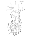
より詳細には、第2給紙トレイ61を、図5に示す完全装着状態から、半装着状態であって図7に示す位置まで移動させると、ピニオンギヤ73とラックギヤ74とが噛み合い始める。そして、この状態からさらに第2給紙トレイ61を前方に移動させると、図8に示すように、ピニオンギヤ73がラックギヤ74との噛み合いにより、図8中反時計回りに回転しつつ上方に移動する。つまり、ピニオンギヤ73とともにローラ71も図5に示す離隔位置から図8に示す当接位置へと移動するとともに、図8中反時計回りに回転する。このため、ローラ71が巻回体P2aの外周面P2a1と当接し、ローラ71によって巻回体P2aが回転軸心Cを中心として、図8中時計回りに回転する。
そして、第2給紙トレイ61をさらに前方へと移動させると、ピニオンギヤ73とラックギヤ74とが噛み合っている間、ローラ71が図8中時計回りに回転し、その後、図9に示すように、ピニオンギヤ73がラックギヤ74よりも前方に移動して、両者の噛み合いがなくなるときには、ローラ71の回転も停止する。このとき、ピニオンギヤ73とともにローラ71が図8に示す当接位置から図9に示す離隔位置へと移動する。また、第2給紙トレイ61を筐体60から取り外す動作に連動したローラ71による巻回体P2aの回転は、ピニオンギヤ73がラックギヤ74と噛み合っている間、行われる。この巻回体P2aの回転による媒体P2の巻き戻しにより、媒体P2の先端は、図9に示すように、搬送ガイド61dの後端とトレイ本体61aとの間に配置される。つまり、回転機構70は、第2給紙トレイ61を完全装着状態からピニオンギヤ73がラックギヤ74よりも前方に位置する位置(ピニオンギヤ73とラックギヤ74との噛み合いが終わる位置)まで抜き出すことで、媒体P2の先端が搬送路91から図5に示す第2給紙ローラ81とトレイ本体61aの底部61a2との当接点の手前まで移動するように、巻回体P2aを回転させるように構成されている。なお、回転機構70は、第2給紙トレイ61を完全装着状態からピニオンギヤ73がラックギヤ74よりも前方に位置する位置まで抜き出したときに、媒体P2の先端が、トレイ本体61aの斜壁部61a1の上端よりも下方に位置する位置まで、巻回体P2aを回転させることが可能であればよい。
この後、第2給紙トレイ61を筐体60から取り外してから、ユーザが第2給紙トレイ61を後方に移動させて、筐体60に再装着させる。このとき、ピニオンギヤ73とラックギヤ74とが噛み合ってピニオンギヤ73が図5中時計回りに回転するが、動力伝達部72により、ピニオンギヤ73の回転力がローラ71に伝達されず、ローラ71は巻回体P2aを回転させない。したがって、媒体P2の先端は、第2給紙トレイ61を筐体60に装着させる際に移動せずに、トレイ本体61a内、すなわち、斜壁部61a1の上端よりも下方に位置した状態となる。このように第2給紙トレイ61を筐体60から抜き出し、その後、筐体60に装着しても、媒体P2の先端がトレイ本体61a内に配置されているため、第2給紙トレイ61の装着時において、媒体P2の先端が第2給送部80や筐体60の構成要素に接触しなくなる。このため、媒体P2の先端を折れ曲がらせずに、第2給紙トレイ61を筐体60に装着することが可能となる。
以上に述べたように、本実施形態の給紙ユニット3によると、筐体60から第2給紙トレイ61を取り外す際に、巻回体P2aから巻き出された媒体P2の一部が巻回体P2aに巻き戻され、媒体P2の先端が搬送路91から第2給紙トレイ61内に引き戻される。このため、第2給紙トレイ61を筐体60に再度装着するときに、媒体P2の先端が筐体60などに接触しにくくなり、折れ曲がりにくくなる。したがって、筐体60に対する第2給紙トレイ60の着脱動作を行っても媒体P2の先端が折れ曲がりにくくなるため、媒体P2を給送する際に媒体P2のジャムなどの給紙不良が生じるのを抑制することが可能となる。
回転機構70が、ローラ71と、ピニオンギヤ73と、ラックギヤ74とを有しているため、比較的簡単な構成で、筐体60から第2給紙トレイ61を取り外す際に、ローラ71を回転させて巻回体P2aを回転させることが可能となる。
第2給紙トレイ61が、トレイ本体61aと、支持台61bとを有しており、ローラ71がトレイ本体61aに支持されているため、筐体60から第2給紙トレイ61を取り外す際に、支持台61bに載せた媒体P2の巻回体P2aをローラ71で回転させることが可能となる。
トレイ本体61aは、支持台61bを取り外した状態において、単票用紙を収容可能に構成されているため、当該単票用紙を給紙することも可能となる。
ピニオンギヤ73は、ローラ74よりも直径が小さいため、筐体60から第2給紙トレイ61を取り外す際の移動距離が短くても、ラックギヤ74に対して比較的多く回転させることができる。したがって、ローラ71も所望数だけ回転させることが可能となり、巻回体P2aを必要な分だけ回転させることが可能となる。
ローラ71は、ラックギヤ74とピニオンギヤ73とが噛み合っていないときに離隔位置に配置され、ラックギヤ74とピニオンギヤ73とが噛み合うことで、離隔位置から当接位置に位置付けられる。これにより、第2給紙トレイ61の完全装着状態においては、ローラ71が離隔位置に配置されるため、媒体P2の給紙時にローラ71による搬送負荷が生じない。
回転機構70が、動力伝達部72を有していることで、第2給紙トレイ61を装着する際に媒体P2の先端が移動して筐体60などに接触するのを抑制することが可能となる。
回転機構70は、第2給紙トレイ61を筐体60から取り外したときの媒体P2の先端が、第2給紙トレイ61を筐体60に装着するときの第2給紙トレイ61の先端部(図5中後端部)の上端よりも下方に配置されるように、巻回体P2aを回転させる。これにより、第2給紙トレイ61を筐体60に再度装着するときに、媒体P2の先端が筐体60などにより一層接触しにくくなる。
以上、本発明の好適な実施の形態について説明したが、本発明は上述の実施の形態に限られるものではなく、特許請求の範囲に記載した限りにおいて様々な変更が可能なものである。例えば、上述の給紙ユニット3は、プリンタ本体2に着脱可能な増設用ユニットであるが、プリンタ本体2に一体的に固定されていてもよい。さらに、プリンタ本体2の筐体11及び第1給紙トレイ15に回転機構70と同様な回転機構を設けて、プリンタ本体2自体に給紙ユニットが設けられていてもよい。これにおいても、上述の実施形態と同様の効果を得ることができる。
回転機構70は、ローラ71、ピニオンギヤ73、ラックギヤ74を有しているが、第2給紙トレイ61を筐体60に装着された状態から前方に移動させて取り外す際に、媒体P2が巻回体P2abに巻き戻されるように巻回体P2aを回転させることが可能であれば、どのような構成でもよく、特に限定するものではない。例えば、第2給紙トレイ61を前方に移動させる際に、巻回体P2aの外周面P2a1と下方において当接するローラの外周面が筐体60と当接することで、当該ローラが回転し巻回体P2aを回転させてもよい。こうすれば、ピニオンギヤ73及びラックギヤ74を有していなくてもよい。
第2給紙トレイ61は、支持台61bを有していなくてもよい。この場合、媒体P2の巻回体P2aの中心に軸部を設け、当該軸部をトレイ本体61aで回転可能に支持すればよい。また、支持台61bは、トレイ本体61aに固定されていてもよい。また、押圧部61cは、トレイ本体61aに設けられていなくてもよい。また、押圧部61cは、筐体60に設けられていてもよく、上述と同様の効果を得ることができる。
ピニオンギヤ73は、ローラ71以上の直径を有していてもよい。この場合、ピニオンギヤ73を、巻回体P2aと接触しない位置に配置することが望ましい。また、ローラ71は、当接位置にだけ位置付けられていてもよい。この場合、第2給紙トレイ61が筐体60に完全装着されている状態において、ピニオンギヤ73とラックギヤ74と噛み合っていないことが望ましい。こうすれば、巻回体P2aとローラ71とが当接していても、巻回体P2aの回転によってローラ71を回転させることが可能となり、媒体P2の給紙時にローラ71による搬送負荷が抑制することができる。
回転機構70が、動力伝達部72を有していなくてもよい。この場合、第2給紙トレイ61を筐体60から取り外す際の媒体P2の巻き取りを、媒体P2の先端が筐体60などに接触するまでに行うように構成する。これにより、第2給紙トレイ61を筐体60に装着する際に、媒体P2の先端が筐体60等に接触するのを抑制することが可能となる。
回転機構70は、第2給紙トレイ61を筐体60から取り外す際に、巻回体P2aを回転させて媒体P2を巻き戻すことが可能であれば、媒体P2の先端が、第2給紙トレイ61を筐体60に装着するときの第2給紙トレイ61の先端部の上端よりも若干上方に配置されていてもよい。これにおいても、第2給紙トレイ61を筐体60に再度装着するときに、媒体P2の先端が筐体60などに接触しにくくなり、折れ曲がりにくくなる。
また、以上では、用紙Pに記録を行うプリンタに本発明を適用した例について説明したが、これには限られない。媒体P2の巻回体P2aを回転可能に収容可能な給紙ユニット全体に適用され得る。
3 給紙ユニット
60 筐体
61 第2給紙トレイ(給紙トレイ)
61a トレイ本体
61b 支持台
61c 押圧部
70 引き戻し機構(回転機構)
71 ローラ
72 動力伝達部
73 ピニオンギヤ
74 ラックギヤ
60 筐体
61 第2給紙トレイ(給紙トレイ)
61a トレイ本体
61b 支持台
61c 押圧部
70 引き戻し機構(回転機構)
71 ローラ
72 動力伝達部
73 ピニオンギヤ
74 ラックギヤ
Claims (11)
- 媒体がロール状に巻回された巻回体を回転可能に収容可能な給紙トレイと、前記給紙トレイを着脱可能に支持する筐体とを備えた給紙ユニットにおいて、
前記巻回体の回転軸心と直交する方向に前記給紙トレイを移動させて前記筐体から前記給紙トレイを取り外す動作に連動して、前記巻回体から巻き出された媒体を引き戻す引き戻し機構を備えていることを特徴とする給紙ユニット。 - 前記引き戻し機構は、前記給紙トレイを取り外す動作に連動して、前記巻回体から巻き出された媒体を引き戻すように回転する回転機構を有していることを特徴とする請求項1に記載の給紙ユニット。
- 前記回転機構は、前記巻回体から巻き出された媒体が前記巻回体に巻き戻されるように前記巻回体を回転させることを特徴とする請求項2に記載の給紙ユニット。
- 前記回転機構は、
前記給紙トレイに回転可能に支持され、前記巻回体の外周面と当接しながら回転することで前記巻回体を回転させるローラと、
前記ローラに回転力を伝達するピニオンギヤと、
前記筐体に設けられ、前記給紙トレイの前記直交する方向の移動に伴って前記ピニオンギヤを回転させるように噛み合うラックギヤとを有していることを特徴とする請求項3に記載の給紙ユニット。 - 前記給紙トレイは、トレイ本体と、前記トレイ本体上に配置され前記巻回体の前記外周面を下方から支持する支持台を有しており、
前記トレイ本体は、前記ローラが前記巻回体の前記外周面の下方部分に当接しつつ回転可能なように、前記ローラを支持していることを特徴とする請求項4に記載の給紙ユニット。 - 前記トレイ本体には、前記巻回体を前記支持台に向けて押圧する押圧部が設けられていることを特徴とする請求項5に記載の給紙ユニット。
- 前記支持台は、前記トレイ本体に対して着脱可能に構成されており、
前記トレイ本体は、前記支持台を取り外した状態において、単票用紙を収容可能に構成されていることを特徴とする請求項5又は6に記載の給紙ユニット。 - 前記ピニオンギヤは、前記ローラよりも直径が小さいことを特徴とする請求項4~7のいずれか1項に記載の給紙ユニット。
- 前記ローラは、前記巻回体の前記外周面から離隔する離隔位置と、前記巻回体の前記外周面と当接する当接位置との間を移動可能に支持されており、
前記ラックギヤは、前記給紙トレイが前記筐体に完全に装着された完全装着状態において前記ピニオンギヤと噛み合わない位置に配置され、前記給紙トレイを前記完全装着状態から前記直交する方向に移動させて前記筐体から取り外されるまでの間の半装着状態において前記ピニオンギヤの下方部分と噛み合う位置に配置され、
前記ローラは、前記ラックギヤと前記ピニオンギヤとが噛み合っていないときに前記離隔位置に配置され、前記ラックギヤと前記ピニオンギヤとが噛み合うことで、前記離隔位置から前記当接位置に位置付けられることを特徴とする請求項4~8のいずれか1項に記載の給紙ユニット。 - 前記回転機構は、前記ピニオンギヤからの回転力を前記ローラに伝達する動力伝達部をさらに備えており、
前記動力伝達部は、前記給紙トレイを前記筐体から取り外す際に、前記ラックギヤと噛み合うことで回転する前記ピニオンギヤの回転力を前記ローラに伝達し、前記給紙トレイを前記筐体に装着する際に、前記ラックギヤと噛み合うことで回転する前記ピニオンギヤの回転力を前記ローラに伝達しないことを特徴とする請求項4~9のいずれか1項に記載の給紙ユニット。 - 前記回転機構は、前記給紙トレイを前記筐体から取り外したときの媒体の先端が、前記給紙トレイを前記筐体に装着するときの前記給紙トレイの先端部の上端よりも下方に配置されるように、前記巻回体を回転させることを特徴とする請求項3~10のいずれか1項に記載の給紙ユニット。
Priority Applications (2)
| Application Number | Priority Date | Filing Date | Title |
|---|---|---|---|
| CN202080066946.1A CN114450238B (zh) | 2019-09-30 | 2020-09-25 | 供纸单元 |
| US17/702,726 US20220212888A1 (en) | 2019-09-30 | 2022-03-23 | Feed device |
Applications Claiming Priority (2)
| Application Number | Priority Date | Filing Date | Title |
|---|---|---|---|
| JP2019180734A JP7294038B2 (ja) | 2019-09-30 | 2019-09-30 | 給紙ユニット |
| JP2019-180734 | 2019-09-30 |
Related Child Applications (1)
| Application Number | Title | Priority Date | Filing Date |
|---|---|---|---|
| US17/702,726 Continuation US20220212888A1 (en) | 2019-09-30 | 2022-03-23 | Feed device |
Publications (1)
| Publication Number | Publication Date |
|---|---|
| WO2021065708A1 true WO2021065708A1 (ja) | 2021-04-08 |
Family
ID=75269665
Family Applications (1)
| Application Number | Title | Priority Date | Filing Date |
|---|---|---|---|
| PCT/JP2020/036238 WO2021065708A1 (ja) | 2019-09-30 | 2020-09-25 | 給紙ユニット |
Country Status (4)
| Country | Link |
|---|---|
| US (1) | US20220212888A1 (ja) |
| JP (1) | JP7294038B2 (ja) |
| CN (1) | CN114450238B (ja) |
| WO (1) | WO2021065708A1 (ja) |
Citations (4)
| Publication number | Priority date | Publication date | Assignee | Title |
|---|---|---|---|---|
| JP2002348011A (ja) * | 2001-03-16 | 2002-12-04 | Canon Inc | 記録装置 |
| JP2003080778A (ja) * | 2001-06-27 | 2003-03-19 | Ricoh Co Ltd | シート給送装置及び画像形成装置 |
| JP2011510883A (ja) * | 2008-01-04 | 2011-04-07 | イーストマン コダック カンパニー | 画像発現先媒体シート用デュアルトレイ |
| JP2012158442A (ja) * | 2011-02-01 | 2012-08-23 | Seiko Epson Corp | 記録装置 |
Family Cites Families (45)
| Publication number | Priority date | Publication date | Assignee | Title |
|---|---|---|---|---|
| DE69006075T2 (de) * | 1989-04-03 | 1994-05-05 | Sharp Kk | Blattfördervorrichtung für Faksimilegerät. |
| US5440328A (en) * | 1992-10-05 | 1995-08-08 | Atlantek, Inc. | Single-pass multi-color thermal printer |
| JPH10291707A (ja) * | 1997-04-15 | 1998-11-04 | Brother Ind Ltd | ウエッブロール及びウエッブロール収納カセット |
| JP3721745B2 (ja) * | 1997-10-17 | 2005-11-30 | ブラザー工業株式会社 | 記録装置 |
| JP3134871B1 (ja) * | 1999-09-27 | 2001-02-13 | 神鋼電機株式会社 | 昇華型カラープリンタ装置 |
| JP2002067435A (ja) * | 2000-08-31 | 2002-03-05 | Alps Electric Co Ltd | プリンタ |
| JP3818368B2 (ja) * | 2000-09-07 | 2006-09-06 | セイコーエプソン株式会社 | 両面印刷装置 |
| US6592217B2 (en) * | 2001-03-16 | 2003-07-15 | Canon Kabushiki Kaisha | Recording apparatus |
| EP1454760B1 (en) * | 2003-03-05 | 2009-11-18 | Brother Kogyo Kabushiki Kaisha | Cassette for rolled recording medium and image forming apparatus |
| JP3897007B2 (ja) * | 2003-07-31 | 2007-03-22 | ブラザー工業株式会社 | インクジェットプリンタ |
| JP2008213989A (ja) * | 2007-03-01 | 2008-09-18 | Noritsu Koki Co Ltd | 記録材料供給装置およびこれを備えた画像形成装置 |
| JP4983623B2 (ja) * | 2008-01-29 | 2012-07-25 | Nkワークス株式会社 | デカール機構 |
| JP5482262B2 (ja) * | 2010-02-08 | 2014-05-07 | セイコーエプソン株式会社 | 記録装置 |
| JP5471583B2 (ja) * | 2010-02-24 | 2014-04-16 | セイコーエプソン株式会社 | ロール媒体給送装置及び記録装置 |
| JP5423480B2 (ja) * | 2010-03-03 | 2014-02-19 | セイコーエプソン株式会社 | ロール状媒体収容装置および液体噴射装置 |
| JP5577941B2 (ja) * | 2010-08-20 | 2014-08-27 | セイコーエプソン株式会社 | ロール状媒体給送装置及び記録装置 |
| JP5617466B2 (ja) * | 2010-09-15 | 2014-11-05 | セイコーエプソン株式会社 | 記録装置および記録・カット制御方法 |
| JP2012131630A (ja) * | 2010-12-24 | 2012-07-12 | Seiko Epson Corp | 被記録媒体カセット、被記録媒体給送装置、記録装置 |
| US9193191B2 (en) * | 2012-04-02 | 2015-11-24 | Toshiba Tec Kabushiki Kaisha | Printer |
| US9283784B2 (en) * | 2012-04-02 | 2016-03-15 | Toshiba Tec Kabushiki Kaisha | Printer |
| JP6209871B2 (ja) * | 2012-10-06 | 2017-10-11 | 株式会社リコー | 画像形成装置、印刷媒体のセット方法 |
| JP6205719B2 (ja) * | 2012-12-27 | 2017-10-04 | セイコーエプソン株式会社 | ロール媒体支持装置及び記録装置 |
| CN104129176B (zh) * | 2013-05-02 | 2017-10-27 | 山东新北洋信息技术股份有限公司 | 纸仓、打印机和多类型介质的使用方法 |
| JP6819852B2 (ja) * | 2016-06-30 | 2021-01-27 | セイコーエプソン株式会社 | 媒体排出装置、画像読取装置 |
| JP6880927B2 (ja) * | 2017-03-30 | 2021-06-02 | ブラザー工業株式会社 | シート給送装置 |
| JP7230577B2 (ja) * | 2019-02-21 | 2023-03-01 | セイコーエプソン株式会社 | 搬送装置及び記録装置 |
| CN113213213A (zh) * | 2020-02-05 | 2021-08-06 | 兄弟工业株式会社 | 介质盒和图像记录设备 |
| JP2021130286A (ja) * | 2020-02-21 | 2021-09-09 | セイコーエプソン株式会社 | 印刷装置 |
| JP2021155199A (ja) * | 2020-03-27 | 2021-10-07 | ブラザー工業株式会社 | 媒体カセット |
| CN113459665B (zh) * | 2020-03-30 | 2024-03-29 | 精工爱普生株式会社 | 打印机以及打印机的控制方法 |
| JP2021160851A (ja) * | 2020-03-31 | 2021-10-11 | ブラザー工業株式会社 | 媒体カセット |
| JP7463805B2 (ja) * | 2020-03-31 | 2024-04-09 | ブラザー工業株式会社 | 媒体ユニット |
| JP2022038687A (ja) * | 2020-08-27 | 2022-03-10 | セイコーエプソン株式会社 | 記録装置 |
| JP2022048548A (ja) * | 2020-09-15 | 2022-03-28 | セイコーエプソン株式会社 | 記録装置、記録装置の制御方法 |
| CN114563935A (zh) * | 2020-11-27 | 2022-05-31 | 兄弟工业株式会社 | 图像形成装置 |
| JP2022104672A (ja) * | 2020-12-29 | 2022-07-11 | ブラザー工業株式会社 | 画像形成装置 |
| JP2022104674A (ja) * | 2020-12-29 | 2022-07-11 | ブラザー工業株式会社 | 画像形成装置及び給送トレイ |
| JP2022104657A (ja) * | 2020-12-29 | 2022-07-11 | ブラザー工業株式会社 | 給送機構、画像形成装置及び給送トレイ |
| CN114690599A (zh) * | 2020-12-29 | 2022-07-01 | 兄弟工业株式会社 | 图像形成装置 |
| CN114684634A (zh) * | 2020-12-29 | 2022-07-01 | 兄弟工业株式会社 | 图像形成装置 |
| JP2022115564A (ja) * | 2021-01-28 | 2022-08-09 | ブラザー工業株式会社 | 給送トレイ及びそれを備えた画像記録装置 |
| JP2023034427A (ja) * | 2021-08-31 | 2023-03-13 | ブラザー工業株式会社 | 給送トレイ、及び、これを備えた画像形成装置 |
| JP2023050317A (ja) * | 2021-09-30 | 2023-04-11 | ブラザー工業株式会社 | 画像記録装置 |
| JP2023090101A (ja) * | 2021-12-17 | 2023-06-29 | セイコーエプソン株式会社 | 印刷装置、印刷装置の制御方法 |
| JP2023162610A (ja) * | 2022-04-27 | 2023-11-09 | ブラザー工業株式会社 | 画像記録装置、その制御方法及びプログラム |
-
2019
- 2019-09-30 JP JP2019180734A patent/JP7294038B2/ja active Active
-
2020
- 2020-09-25 WO PCT/JP2020/036238 patent/WO2021065708A1/ja active Application Filing
- 2020-09-25 CN CN202080066946.1A patent/CN114450238B/zh active Active
-
2022
- 2022-03-23 US US17/702,726 patent/US20220212888A1/en active Pending
Patent Citations (4)
| Publication number | Priority date | Publication date | Assignee | Title |
|---|---|---|---|---|
| JP2002348011A (ja) * | 2001-03-16 | 2002-12-04 | Canon Inc | 記録装置 |
| JP2003080778A (ja) * | 2001-06-27 | 2003-03-19 | Ricoh Co Ltd | シート給送装置及び画像形成装置 |
| JP2011510883A (ja) * | 2008-01-04 | 2011-04-07 | イーストマン コダック カンパニー | 画像発現先媒体シート用デュアルトレイ |
| JP2012158442A (ja) * | 2011-02-01 | 2012-08-23 | Seiko Epson Corp | 記録装置 |
Also Published As
| Publication number | Publication date |
|---|---|
| CN114450238A (zh) | 2022-05-06 |
| JP2021054614A (ja) | 2021-04-08 |
| CN114450238B (zh) | 2023-06-20 |
| JP7294038B2 (ja) | 2023-06-20 |
| US20220212888A1 (en) | 2022-07-07 |
Similar Documents
| Publication | Publication Date | Title |
|---|---|---|
| US8141971B2 (en) | Image recording apparatus | |
| JP4221609B2 (ja) | 給送装置及び画像記録装置 | |
| JP4985015B2 (ja) | ロール状媒体支持装置及び記録装置 | |
| EP2065207B1 (en) | Recording device having a conveying unit that conveys a recording medium | |
| US8503923B2 (en) | Image recording apparatus | |
| JP4788467B2 (ja) | インクジェット記録装置 | |
| JP2022104672A (ja) | 画像形成装置 | |
| WO2021065708A1 (ja) | 給紙ユニット | |
| WO2021065709A1 (ja) | 給紙ユニット | |
| JP5573700B2 (ja) | 搬送装置及びインクジェット記録装置 | |
| US9650221B2 (en) | Conveyor | |
| JP4582037B2 (ja) | 記録装置 | |
| JP6176173B2 (ja) | 給送装置及び画像記録装置 | |
| US9815645B2 (en) | Conveyance apparatus and image recording apparatus | |
| JP2011051697A (ja) | 画像記録装置 | |
| JP2006015533A (ja) | 記録装置および液体噴射装置 | |
| JP2015231690A (ja) | インクジェット記録装置 | |
| JP2017132222A (ja) | 画像記録装置 | |
| JP6728896B2 (ja) | 画像記録装置 | |
| JP5488665B2 (ja) | 記録装置 | |
| JP2016185619A (ja) | インクジェットプリンター | |
| JP2006264905A (ja) | 給紙装置及び画像形成装置 | |
| JP2002096540A (ja) | 記録装置 | |
| JP2017065899A (ja) | 搬送装置 | |
| JP2003266857A (ja) | 記録装置 |
Legal Events
| Date | Code | Title | Description |
|---|---|---|---|
| 121 | Ep: the epo has been informed by wipo that ep was designated in this application |
Ref document number: 20872406 Country of ref document: EP Kind code of ref document: A1 |
|
| NENP | Non-entry into the national phase |
Ref country code: DE |
|
| 122 | Ep: pct application non-entry in european phase |
Ref document number: 20872406 Country of ref document: EP Kind code of ref document: A1 |