WO2020183939A1 - 電磁シールド部材及びワイヤハーネス - Google Patents
電磁シールド部材及びワイヤハーネス Download PDFInfo
- Publication number
- WO2020183939A1 WO2020183939A1 PCT/JP2020/002531 JP2020002531W WO2020183939A1 WO 2020183939 A1 WO2020183939 A1 WO 2020183939A1 JP 2020002531 W JP2020002531 W JP 2020002531W WO 2020183939 A1 WO2020183939 A1 WO 2020183939A1
- Authority
- WO
- WIPO (PCT)
- Prior art keywords
- pressing
- electric wire
- electromagnetic shield
- shield member
- portions
- Prior art date
- Legal status (The legal status is an assumption and is not a legal conclusion. Google has not performed a legal analysis and makes no representation as to the accuracy of the status listed.)
- Ceased
Links
Images


Classifications
-
- H—ELECTRICITY
- H05—ELECTRIC TECHNIQUES NOT OTHERWISE PROVIDED FOR
- H05K—PRINTED CIRCUITS; CASINGS OR CONSTRUCTIONAL DETAILS OF ELECTRIC APPARATUS; MANUFACTURE OF ASSEMBLAGES OF ELECTRICAL COMPONENTS
- H05K9/00—Screening of apparatus or components against electric or magnetic fields
- H05K9/0007—Casings
- H05K9/0018—Casings with provisions to reduce aperture leakages in walls, e.g. terminals, connectors, cables
-
- B—PERFORMING OPERATIONS; TRANSPORTING
- B60—VEHICLES IN GENERAL
- B60R—VEHICLES, VEHICLE FITTINGS, OR VEHICLE PARTS, NOT OTHERWISE PROVIDED FOR
- B60R16/00—Electric or fluid circuits specially adapted for vehicles and not otherwise provided for; Arrangement of elements of electric or fluid circuits specially adapted for vehicles and not otherwise provided for
- B60R16/02—Electric or fluid circuits specially adapted for vehicles and not otherwise provided for; Arrangement of elements of electric or fluid circuits specially adapted for vehicles and not otherwise provided for electric constitutive elements
- B60R16/0207—Wire harnesses
- B60R16/0215—Protecting, fastening and routing means therefor
-
- H—ELECTRICITY
- H01—ELECTRIC ELEMENTS
- H01B—CABLES; CONDUCTORS; INSULATORS; SELECTION OF MATERIALS FOR THEIR CONDUCTIVE, INSULATING OR DIELECTRIC PROPERTIES
- H01B7/00—Insulated conductors or cables characterised by their form
-
- H—ELECTRICITY
- H01—ELECTRIC ELEMENTS
- H01B—CABLES; CONDUCTORS; INSULATORS; SELECTION OF MATERIALS FOR THEIR CONDUCTIVE, INSULATING OR DIELECTRIC PROPERTIES
- H01B7/00—Insulated conductors or cables characterised by their form
- H01B7/17—Protection against damage caused by external factors, e.g. sheaths or armouring
- H01B7/18—Protection against damage caused by wear, mechanical force or pressure; Sheaths; Armouring
-
- H—ELECTRICITY
- H01—ELECTRIC ELEMENTS
- H01B—CABLES; CONDUCTORS; INSULATORS; SELECTION OF MATERIALS FOR THEIR CONDUCTIVE, INSULATING OR DIELECTRIC PROPERTIES
- H01B7/00—Insulated conductors or cables characterised by their form
- H01B7/42—Insulated conductors or cables characterised by their form with arrangements for heat dissipation or conduction
-
- H—ELECTRICITY
- H02—GENERATION; CONVERSION OR DISTRIBUTION OF ELECTRIC POWER
- H02G—INSTALLATION OF ELECTRIC CABLES OR LINES, OR OF COMBINED OPTICAL AND ELECTRIC CABLES OR LINES
- H02G3/00—Installations of electric cables or lines or protective tubing therefor in or on buildings, equivalent structures or vehicles
- H02G3/02—Details
- H02G3/04—Protective tubing or conduits, e.g. cable ladders or cable troughs
- H02G3/0406—Details thereof
- H02G3/0418—Covers or lids; Their fastenings
-
- H—ELECTRICITY
- H02—GENERATION; CONVERSION OR DISTRIBUTION OF ELECTRIC POWER
- H02G—INSTALLATION OF ELECTRIC CABLES OR LINES, OR OF COMBINED OPTICAL AND ELECTRIC CABLES OR LINES
- H02G3/00—Installations of electric cables or lines or protective tubing therefor in or on buildings, equivalent structures or vehicles
- H02G3/02—Details
- H02G3/04—Protective tubing or conduits, e.g. cable ladders or cable troughs
- H02G3/0462—Tubings, i.e. having a closed section
- H02G3/0487—Tubings, i.e. having a closed section with a non-circular cross-section
Definitions
- the present invention relates to an electromagnetic shield member and a wire harness including the electromagnetic shield member and an electric wire.
- a wire harness applied to a vehicle such as an electric vehicle includes a plurality of electric wires and an electromagnetic shield member having conductivity and performing electromagnetic shielding by individually covering the plurality of electric wires (for example).
- Patent Document 1 The electromagnetic shield member described in Document 1 includes a shield protector having a groove-shaped accommodating portion capable of individually accommodating each electric wire, and a cover for closing the groove-shaped accommodating portion. Then, each electric wire is electromagnetically shielded by covering the outer circumference of each electric wire with the shield protector and the cover.
- An object of the present invention is to provide an electromagnetic shield member and a wire harness that can enhance the heat dissipation of an electric wire.
- the electromagnetic shield member for achieving the above object includes a case having a groove in which an electric wire is housed, a cover attached to the case and covering the groove, and a pressing mechanism housed in the groove and pressing the electric wire.
- the pressing mechanism includes a wall portion that surrounds the outer periphery of the electric wire together with the groove portion, and a pressing portion that is provided on the wall portion and presses the electric wire.
- a pressing mechanism having a pressing portion for pressing the electric wire is provided in the groove portion of the case. Since the pressing portion is provided on the wall portion surrounding the outer circumference of the electric wire together with the groove portion of the case, the electric wire is pressed by the pressing portion by accommodating the electric wire in the electromagnetic shield member. Therefore, the heat of the electric wire is easily dissipated through the wall portion including the pressing portion.
- the wall portion of the pressing mechanism includes a pair of facing wall portions facing each other in the width direction of the groove portion, and the pressing portion is provided on at least one of the pair of facing wall portions, and the other. It is preferable to press the electric wire toward.
- the pressing portion is provided on at least one of the pair of facing wall portions. Therefore, when an extra length is generated in the electric wire due to thermal expansion, the electric wire is bent in the width direction while being pressed by the pressing portion. As a result, the extra length of the electric wire is absorbed and the state where the pressing portion is in contact with the outer peripheral surface of the electric wire is maintained. Therefore, even if the electric wire has an extra length, the heat of the electric wire is easily dissipated through the facing wall portion including the pressing portion.
- the pressing portions are provided on both of the pair of facing wall portions.
- the pressing portions are provided on both of the pair of facing wall portions, the electric wires are pressed from both sides in the width direction. Therefore, as compared with the configuration in which the electric wire is pressed by the pressing portion only from one side in the width direction, each pressing portion and the electric wire are easily brought into close contact with each other, and the contact area between each pressing portion and the electric wire is increased. Therefore, the heat of the electric wire is more easily dissipated through the facing wall portion including the pressing portion.
- each of the pressing portions is provided at different positions in the extending direction of the groove portion.
- the pressing portions are provided at different positions in the extending direction of the groove portions. Therefore, the portion of the electric wire that is pressed toward one side in the width direction and the portion that is pressed toward the other side in the width direction are at different positions in the extending direction. As a result, when an extra length due to thermal expansion is generated in the electric wire, the electric wire is curved to one side and the other side in the width direction at different positions in the extending direction. Therefore, it is possible to suitably absorb the extra length of the electric wire while keeping each pressing portion and the electric wire in close contact with each other.
- each pressing portion presses the electric wire from both sides in the width direction at different positions in the extending direction. Therefore, the distance that each pressing portion presses the electric wire in order to absorb the predetermined extra length is smaller than the distance that the pressing portion presses the electric wire in the configuration in which the pressing portion is provided only on one side in the width direction. Become. As a result, the distance between the pair of facing wall portions of the pressing mechanism, and by extension, the physique in the width direction of the pressing mechanism can be reduced.
- the pressing portion is preferably formed by cutting up a part of the wall portion.
- the pressing portion and the wall portion are integrally formed. Therefore, the thermal resistance at the interface between the pressing portion and the wall portion is smaller than that in the configuration in which the pressing portion is formed separately from the wall portion. Therefore, the heat of the electric wire is easily dissipated through the pressing portion.
- the pressing mechanism includes an urging member that urges the pressing portion toward the electric wire.
- the pressing portion since the pressing portion is urged toward the electric wire by the urging member, when the electric wire is curved due to an extra length due to thermal expansion, the pressing portion follows the curvature of the electric wire. This makes it suitable for contact with the outer peripheral surface of the electric wire. Therefore, the heat of the electric wire is easily dissipated through the pressing portion.
- the tip of the pressing portion is provided with a regulating portion that regulates the lifting of the electric wire from the inner surface of the groove portion.
- the regulation portion provided at the tip of the pressing portion suppresses the electric wire from floating from the inner surface of the groove portion of the case. Therefore, the state in which the electric wire and the inner surface of the groove are in contact with each other is easily maintained. Therefore, the heat of the electric wire is easily dissipated through the pressing portion and the groove portion of the case.
- the restricting portion is provided separately from the pressing portion.
- the pressing portion and the regulating portion are the same. Since it is necessary to cut up from the facing wall portion, the degree of freedom in the shape of the regulating portion may decrease.
- the wire harness for achieving the above object includes an electric wire and any one of the above electromagnetic shield members, and the electric wire is pressed by the pressing portion of the pressing mechanism.
- the heat dissipation of the electric wire can be improved.
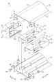
- Electromagnetic shield member and wire harness A perspective view showing a wire harness according to an embodiment. An exploded perspective view showing the electromagnetic shield member of the same embodiment.
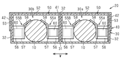
- FIG. 5 is a cross-sectional view taken along the line 4-4 of FIG.
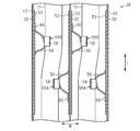
- FIG. 3 is a cross-sectional view showing a wire harness in a state where an extra length is generated in each electric wire, which is a view corresponding to FIG.
- It is a figure which shows the pressing mechanism of the 1st modification (a) is a perspective view which shows the state which the contact member was attached to the pressing part, (b) is centering on the pressing part and contact member. Longitudinal view.
- FIGS. 1 to 5 an embodiment of the electromagnetic shield member and the wire harness will be described with reference to FIGS. 1 to 5.
- a part of the configuration may be exaggerated or simplified for convenience of explanation.
- the dimensional ratio of each part may differ from the actual one.
- the wire harness of the present embodiment is laid out on a route including under the floor of a vehicle such as a hybrid vehicle or an electric vehicle, and a plurality of devices are electrically connected to each other.
- the wire harness includes two electric wires 10 arranged side by side and a conductive electromagnetic shield member 20 that covers each electric wire 10.
- the electric wire 10 has, for example, a core wire and an insulating coating that covers the outer circumference of the core wire. Both ends of each electric wire 10 are connected to the above equipment.
- the electromagnetic shield member 20 is housed in a case 30 having grooves 30a and 30b in which each electric wire 10 is individually housed, a cover 40 attached to the case 30 and covering the grooves 30a and 30b, and the grooves 30a and 30b. It is provided with a plurality of pressing mechanisms 50 for pressing the electric wire 10. In the present embodiment, one pressing mechanism 50 is provided in each of the groove portions 30a and 30b of the case 30.
- the case 30, the cover 40, and the pressing mechanism 50 are each made of a metal material such as an aluminum alloy.
- the extending direction of the groove portions 30a and 30b is referred to as an extending direction L
- the direction orthogonal to the extending direction L and the direction in which the groove portions 30a and 30b are lined up is referred to as a width direction W.
- the case 30 has a bottom wall 31 extending along the extending direction L, and three side walls 32 protruding from both ends of the bottom wall 31 in the width direction W and the central portion in the width direction W. And have.
- Each side wall 32 extends over the entire extending direction L of the bottom wall 31.
- the groove portions 30a and 30b are formed by the bottom wall 31 and a pair of side walls 32 adjacent to each other in the width direction W.
- the groove portion 30a and the groove portion 30b share a side wall 32 located at the center of the width direction W.
- the case 30 has a pair of L-shaped brackets 35 joined to the outer surfaces of the side walls 32 at both ends in the width direction W.
- Each bracket 35 has a joint portion 36 joined to one end of the side wall 32 in the extending direction L, and a mounting portion 37 bent from one end of the joining portion 36 in the extending direction L.
- Each mounting portion 37 is formed with a mounting hole 38 penetrating in the extending direction L.
- Each mounting portion 37 is flush with one end surface of each side wall 32 in the extending direction L.
- the cover 40 extends along the extending direction L and protrudes from both ends of the facing wall 41 facing the bottom wall 31 of the case 30 and the width direction W of the facing wall 41. It has a side wall 42. Each side wall 42 extends over the entire extending direction L of the facing wall 41.
- each side wall 42 of the cover 40 covers the side walls 32 at both ends of the case 30 in the width direction W from the outside in the width direction W.
- the cover 40 has a pair of L-shaped brackets 45 joined to the outer surfaces of the side walls 42 at both ends in the width direction W.
- Each bracket 45 has a joint portion 46 joined to one end of the side wall 42 in the extending direction L, and a mounting portion 47 bent from one end of the joining portion 46 in the extending direction L.
- Each mounting portion 47 is formed with a mounting hole 48 penetrating in the extending direction L.
- each side wall 42 in the extending direction L a relief portion 49 for releasing the joint portion 36 of the bracket 35 of the case 30 is cut out and formed when the cover 40 is attached to the case 30.
- the joint portion 46 of each bracket 45 covers each relief portion 49 from the outside in the width direction W.
- Each bracket 35 of the case 30 and each bracket 45 of the cover 40 are overlapped in the extending direction L, and the nut 101 is inserted into the bolt 100 inserted into the mounting hole 38 of each bracket 35 and the mounting hole 48 of each bracket 45.
- the cover 40 is attached to the case 30 by being screwed together.
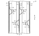
- the pressing mechanism 50 has a wall portion 51 that surrounds the outer circumference of each electric wire 10 together with the bottom wall 31 of the case 30.
- the wall portion 51 extends along the extending direction L and protrudes from both ends of the top wall portion 52 facing the bottom wall 31 of the case 30 and the top wall portion 52 in the width direction W and faces each other in the width direction W. It is composed of a pair of facing wall portions 53. Each facing wall portion 53 extends over the entire extending direction L of the top wall portion 52.
- the facing wall portion 53 on one side of the width direction W (right side in FIG. 3) and the facing wall portion 53 on the other side of the width direction W (left side in FIG. 3) are respectively.
- Pressing portions 55A and 55B are provided, which are formed by cutting a part toward the inside of the width direction W and pressing each electric wire 10 inward in the width direction W.
- the pressing portion 55A is provided on one side (lower side in FIG. 3) of the extending direction L of the facing wall portion 53 on one side.
- the pressing portion 55B is provided on the other side (upper side in FIG. 3) of the extending direction L of the opposite wall portion 53 on the other side. Therefore, the pressing portions 55A and 55B are provided at different positions in the extending direction L.
- the pressing portion 55A is cut up from the facing wall portion 53 with the other side of the extending direction L as the base end and one side of the extending direction L as the tip. Further, the pressing portion 55B is cut up from the facing wall portion 53 with one side of the extending direction L as the base end and the other side of the extending direction L as the tip end. Therefore, the pressing portions 55A and 55B extend in different directions in the extending direction L.
- Each of the pressing portions 55A and 55B has a curved portion 56 curved so as to bulge inward in the width direction W from the facing wall portion 53, and an extending portion 57 extending from the tip of the curved portion 56 along the extending direction L. doing.
- Each electric wire 10 is pressed inward in the width direction W by each extending portion 57 of each pressing portion 55A and 55B.
- a regulation portion 58 for restricting each electric wire 10 from rising from the bottom wall 31 of the case 30 is formed at a portion on the top wall portion 52 side at the tip of each extension portion 57. ing.
- Each regulation portion 58 extends from the above portion of each extension portion 57 so as to abut on the outer peripheral surface of each electric wire 10. Therefore, each electric wire 10 is pressed inward in the width direction W by each extending portion 57 of each pressing portion 55A and 55B, and is pressed inward in the width direction W and toward the bottom wall 31 by each regulating portion 58. Will be done.
- the curved portion 56, the extending portion 57, and the regulating portion 58 are integrally formed.
- Each facing wall portion 53 is provided with a leaf spring 60 as an urging member that urges the pressing portions 55A and 55B toward the electric wires 10.
- Each leaf spring 60 has a rectangular shape extending along the extending direction L. The base end of each leaf spring 60 is joined to the facing wall portion 53 by, for example, welding, and the tip end abuts on the extending portion 57 of the pressing portions 55A and 55B from the outside in the width direction W.
- the leaf spring 60 is formed by bending a metal material such as stainless steel.
- the pressing mechanisms 50 housed in the groove portions 30a and 30b are provided at the same position in the extending direction L.
- each electric wire 10 housed in the electromagnetic shield member 20 is pressed inward in the width direction W by the pressing portions 55A and 55B of each pressing mechanism 50. (The above is action 1).
- each electric wire 10 when an extra length due to thermal expansion is generated in each electric wire 10, each electric wire 10 is curved in the width direction W while being pressed by the pressing portions 55A and 55B. .. As a result, the extra length of each electric wire 10 is absorbed, and the state in which the pressing portions 55A and 55B are in contact with the outer peripheral surface of each electric wire 10 is maintained (the above is the action 2).
- each electric wire 10 has a portion pressed toward one side of the width direction W and the other of the width direction W.
- the portions pressed toward the side are at different positions in the extending direction L.
- each electric wire 10 is curved to one side and the other side in the width direction W at different positions in the extending direction L (the above, the action 3). ).
- the electromagnetic shield member 20 is provided in a case 30 having grooves 30a and 30b in which two electric wires 10 are housed, a cover 40 attached to the case 30 and covering the grooves 30a and 30b, and in the grooves 30a and 30b. It is accommodated and includes a plurality of pressing mechanisms 50 that press each electric wire 10.
- Each pressing mechanism 50 has a pair of facing wall portions 53 facing each other in the width direction W, a wall portion 51 surrounding the outer circumference of each electric wire 10 together with the bottom wall 31 of the case 30, and a pair of facing wall portions of the wall portion 51.
- Each of 53 is provided with pressing portions 55A and 55B for pressing each electric wire 10 inward in the width direction W.
- the pressing portions 55A and 55B are provided at different positions in the extending direction L.
- each electric wire 10 can be suitably absorbed while the pressing portions 55A and 55B and each electric wire 10 are brought into close contact with each other.
- the pressing portions 55A and 55B press each electric wire 10 from both sides in the width direction W at different positions in the extending direction L. Therefore, the distance at which the pressing portions 55A and 55B press the electric wires 10 in order to absorb the predetermined extra length is such that the pressing portions are provided on only one side of the width direction W, and the pressing portions press each electric wire. It is smaller than the distance to press 10. As a result, the distance between the pair of facing wall portions 53 of the pressing mechanism 50, and by extension, the physique of the pressing mechanism 50 in the width direction W can be reduced.
- the pressing portions 55A and 55B are formed by cutting up a part of each facing wall portion 53.
- the pressing portions 55A and 55B and the facing wall portions 53 are integrally formed. Therefore, the thermal resistance at the interface between the pressing portions 55A and 55B and the opposing wall portions 53 is smaller than that in which the pressing portions 55A and 55B are formed separately from the facing wall portions 53. .. Therefore, the heat of each electric wire 10 is easily dissipated through the pressing portions 55A and 55B.
- the pressing mechanism 50 includes a leaf spring 60 as an urging member that urges the pressing portions 55A and 55B toward the electric wires 10.
- each of the pressing portions 55A and 55B is provided with a regulating portion 58 that regulates the lifting of each electric wire 10 from the bottom wall 31 of the case 30.
- the regulation portion 58 provided in the extending portion 57 of the pressing portions 55A and 55B prevents the electric wires 10 from being lifted from the bottom wall 31 of the case 30. Therefore, the state in which each electric wire 10 and the bottom wall 31 of the case 30 are in contact with each other is easily maintained. Therefore, the heat of each electric wire 10 is easily dissipated through the pressing portions 55A and 55B and the bottom wall 31 of the case 30.
- the wire harness includes two electric wires 10 pressed by the pressing portions 55A and 55B of the two pressing mechanisms 50, and an electromagnetic shield member 20.
- This embodiment can be modified and implemented as follows.
- the present embodiment and the following modified examples can be implemented in combination with each other within a technically consistent range.
- each of the pressing portions 155A and 155B is composed of a curved portion 156 and an extending portion 157, and the pressing portions 155A and 155B have a regulating portion 158.
- a contact member 170 that comes into contact with each electric wire 10 may be attached.
- the abutting member 170 has a plate-shaped mounting portion 171 extending along the extending direction L, and a regulating portion 158 formed on a portion of the mounting portion 171 on the top wall portion 52 side.
- a recess 172 is formed on the outer surface of the mounting portion 171 in the width direction W and on one side of the extending direction L so that the tip of the extending portion 157 is inserted and fixed.
- the leaf spring 60 may be provided so as to press the portion of the outer surface of the mounting portion 171 in the width direction W in which the recess 172 is not formed.
- the pressing portion is formed by being cut off from a part of the facing wall portion of the pressing mechanism and the regulating portion is provided integrally with the pressing portion, the pressing portion and the regulating portion are separated. Since it is necessary to cut up from the same facing wall portion, the degree of freedom in the shape of the regulating portion may decrease.
- the contact member 170 having the regulation portion 158 is provided separately from the pressing portions 155A and 155B, it is possible to suppress the above-mentioned inconvenience.
- the contact member 170 may be made of a metal material or a resin material. Further, the contact member 170 and the extending portion 157 may be fixed by welding, adhesion via an adhesive, or the like.
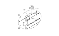
- the restricting portion 58 is omitted, and the pressing portions 255A and 255B composed of the curved portion 256 and the extending portion 157 can be adopted.
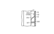
- pressing portions 355A and 355B which are separate from the facing wall portion 53, can also be adopted.
- the pressing portions 355A and 355B may be fixed to the facing wall portion 53 by welding, for example.
- a coil spring 360 for urging the extending portions 357 of the pressing portions 355A and 355B toward the inside of the width direction W can be provided.
- the pressing portions 55A and 55B may be provided at the same position in the extending direction L.
- each pressing mechanism 50 may have a plurality of pressing portions 55A and 55B.
- each pressing mechanism may have only the pressing portion 55A, or may have only the pressing portion 55B.
- the pressing portion may be formed by cutting up a part of the top wall portion 52 of the wall portion 51 and pressing each electric wire 10 toward the bottom wall 31 of the case 30. Even in this case, since the above-mentioned action 1 can be performed, the heat of each electric wire 10 is easily dissipated through the top wall portion 52 including the pressing portion.
- the electromagnetic shield member 20 is not limited to that made of an aluminum alloy. Alternatively, for example, it may be made of stainless steel or the like.
- the electromagnetic shield member 20 may be provided with a plurality of pressing mechanisms 50 provided at intervals in the extending direction L.
- the present invention can also be applied to a wire harness having one electric wire 10 or three or more electric wires 10.
- the mounting posture of the wire harness is not limited to the posture in the above embodiment, and can be changed as appropriate.
- each electric wire 10 may have an arbitrary cross-sectional shape such as a semicircular shape or a polygonal shape on a plane orthogonal to the extending direction L.
- One or more mounting examples of the present disclosure are directed to an electromagnetic shield member (20) configured to electromagnetically shield the electric wire (10), and the electromagnetic shield member (20) is
- a storage chamber (30a) having a first length, which is configured to accommodate a predetermined length portion of the electric wire (10), and the predetermined length portion of the electric wire (10) is provided from below. It has a lower surface (31) configured to support and first and second side surfaces (53) parallel to each other that laterally cover or support the predetermined length portion of the wire (10).
- Containment room (30a) and The second side surface (53) of the accommodation chamber (30a) is arranged at a position in the first length direction of the accommodation chamber (30a), and the electric wire (10) is placed along the lower surface (31).
- a first elastic pressing portion (55A) that elastically presses toward the side surface (53) can be provided.
- the electromagnetic shield member (20) has a second length of the accommodation chamber (30a) on the second side surface (53) of the accommodation chamber (30a).
- a second elastic pressing portion (55B) that is arranged at a directional position and elastically presses the electric wire (10) toward the first side surface (53) along the lower surface (31) can be further provided.
- the first elastic pressing portion (55A) and the second elastic pressing portion (55B) are the entire portion of the predetermined length portion of the electric wire (10). Can be configured to bend the wire (10) along the lower surface (31) so that the wire comes into contact with the lower surface (31).
- the first elastic pressing portion (55A) and the second elastic pressing portion (55B) are the electric wires (10) caused by a temperature change of the electric wires (10).
- the electric wire (10) is placed along the lower surface (31) so that the entire predetermined length portion of the electric wire (10) is in contact with the lower surface (31) regardless of the length change of the electric wire (10).
- the lower surface (31) is in contact with the entire predetermined length portion of the electric wire (10), and the first and second side surfaces (53). ) Is the electric wire () between the first lengthwise position and the second lengthwise position, except for the first elastic pressing portion (55A) and the second elastic pressing portion (55B). It may be non-contact with 10).
Landscapes
- Engineering & Computer Science (AREA)
- Mechanical Engineering (AREA)
- Architecture (AREA)
- Civil Engineering (AREA)
- Structural Engineering (AREA)
- Microelectronics & Electronic Packaging (AREA)
- Insulated Conductors (AREA)
- Shielding Devices Or Components To Electric Or Magnetic Fields (AREA)
- Details Of Indoor Wiring (AREA)
Priority Applications (2)
| Application Number | Priority Date | Filing Date | Title |
|---|---|---|---|
| US17/438,260 US11696425B2 (en) | 2019-03-11 | 2020-01-24 | Electromagnetic shield member and wire harness |
| CN202080020131.XA CN113557803B (zh) | 2019-03-11 | 2020-01-24 | 电磁屏蔽构件及线束 |
Applications Claiming Priority (2)
| Application Number | Priority Date | Filing Date | Title |
|---|---|---|---|
| JP2019043638A JP7052760B2 (ja) | 2019-03-11 | 2019-03-11 | 電磁シールド部材及びワイヤハーネス |
| JP2019-043638 | 2019-03-11 |
Publications (1)
| Publication Number | Publication Date |
|---|---|
| WO2020183939A1 true WO2020183939A1 (ja) | 2020-09-17 |
Family
ID=72427906
Family Applications (1)
| Application Number | Title | Priority Date | Filing Date |
|---|---|---|---|
| PCT/JP2020/002531 Ceased WO2020183939A1 (ja) | 2019-03-11 | 2020-01-24 | 電磁シールド部材及びワイヤハーネス |
Country Status (4)
| Country | Link |
|---|---|
| US (1) | US11696425B2 (enExample) |
| JP (1) | JP7052760B2 (enExample) |
| CN (1) | CN113557803B (enExample) |
| WO (1) | WO2020183939A1 (enExample) |
Families Citing this family (1)
| Publication number | Priority date | Publication date | Assignee | Title |
|---|---|---|---|---|
| US12473996B1 (en) * | 2021-09-01 | 2025-11-18 | Christopher Thomas Harmon | Cable clamp |
Citations (2)
| Publication number | Priority date | Publication date | Assignee | Title |
|---|---|---|---|---|
| JPS5387898U (enExample) * | 1976-12-21 | 1978-07-19 | ||
| JP2005044607A (ja) * | 2003-07-28 | 2005-02-17 | Auto Network Gijutsu Kenkyusho:Kk | シールド機能を備えた導電路 |
Family Cites Families (47)
| Publication number | Priority date | Publication date | Assignee | Title |
|---|---|---|---|---|
| US3749813A (en) * | 1972-05-31 | 1973-07-31 | A Shealy | Expanded self-damping electrical conductor |
| JPH0685470A (ja) * | 1992-09-07 | 1994-03-25 | Fujitsu Ltd | ケーブルクランパ |
| JP3479970B2 (ja) * | 1999-10-04 | 2003-12-15 | 住友電装株式会社 | フラットケーブル用コネクタ |
| JP2001185248A (ja) * | 1999-12-27 | 2001-07-06 | Yazaki Corp | 圧接ジョイントコネクタ |
| JP4146316B2 (ja) * | 2003-09-02 | 2008-09-10 | 矢崎総業株式会社 | プロテクタ |
| US7075010B2 (en) * | 2003-10-23 | 2006-07-11 | Santelli Jr Albert | Electrical conductor management system having electromagnetic radiation shielding properties |
| JP4673726B2 (ja) * | 2005-11-10 | 2011-04-20 | 日産自動車株式会社 | 車両の強電ハーネス配索構造 |
| JP4875412B2 (ja) * | 2006-06-19 | 2012-02-15 | 古河電気工業株式会社 | ワイヤハーネス |
| CN101126468A (zh) * | 2006-08-18 | 2008-02-20 | 前程科技股份有限公司 | 径材固定件 |
| KR20080029264A (ko) * | 2006-09-28 | 2008-04-03 | 주식회사 하이닉스반도체 | 메모리 모듈 |
| US7983058B2 (en) * | 2007-01-29 | 2011-07-19 | Nec Corporation | Shielding structure and member for electronic device and electronic device including the same |
| JP2008204805A (ja) * | 2007-02-20 | 2008-09-04 | Auto Network Gijutsu Kenkyusho:Kk | シールド導電体及びその製造方法 |
| JP4400662B2 (ja) * | 2007-09-12 | 2010-01-20 | 株式会社デンソー | 電子回路部品実装構造 |
| JP2009070981A (ja) * | 2007-09-12 | 2009-04-02 | Brother Ind Ltd | 電気装置の放熱構造及び電気装置の製造方法 |
| DE102009023178A1 (de) * | 2009-05-29 | 2010-12-02 | Rehau Ag + Co. | Befestigungssystem zur Fixierung von Kabeln oder Rohren einer Fußbodenheizung auf Stahlgittermatten |
| JP2011060425A (ja) * | 2009-09-04 | 2011-03-24 | Yazaki Corp | シールドコネクタ |
| CN101697406A (zh) * | 2009-09-10 | 2010-04-21 | 王鸿智 | 电线整理夹 |
| JP2011205843A (ja) * | 2010-03-26 | 2011-10-13 | Toyota Motor Corp | フラット電線用クランプ |
| WO2011158615A1 (ja) * | 2010-06-18 | 2011-12-22 | シャープ株式会社 | 電子機器の放熱構造 |
| KR20120001225U (ko) * | 2010-08-13 | 2012-02-22 | 한국단자공업 주식회사 | 터미널 및 이를 사용한 커넥터 |
| CN202395393U (zh) * | 2011-11-29 | 2012-08-22 | 长城汽车股份有限公司 | 线束固定装置 |
| JP2013229408A (ja) * | 2012-04-25 | 2013-11-07 | Auto Network Gijutsu Kenkyusho:Kk | ワイヤハーネス |
| JP5961031B2 (ja) * | 2012-04-26 | 2016-08-02 | 矢崎総業株式会社 | ワイヤハーネス |
| KR20140001379U (ko) * | 2012-08-28 | 2014-03-10 | 주식회사 유라코퍼레이션 | 와이어링 하네스 고정장치 |
| JP5950303B2 (ja) * | 2012-09-05 | 2016-07-13 | 矢崎総業株式会社 | 布線シート及びそれを有する電気接続箱 |
| JP6247017B2 (ja) * | 2013-04-16 | 2017-12-13 | 日本圧着端子製造株式会社 | 圧接コネクタ及びこれに用いられるハウジング |
| JP6103381B2 (ja) * | 2013-10-25 | 2017-03-29 | 株式会社オートネットワーク技術研究所 | コネクタ構造及びワイヤハーネス |
| CN203607781U (zh) * | 2013-10-31 | 2014-05-21 | 郭东旭 | 一种能规整布线的方形线槽 |
| CN105591333B (zh) * | 2016-03-10 | 2018-03-02 | 重庆星特龙实业有限公司 | 线缆桥架 |
| CN205944926U (zh) * | 2016-05-18 | 2017-02-08 | 重庆星特龙实业有限公司 | 线缆桥架 |
| CN206272927U (zh) * | 2016-11-10 | 2017-06-20 | 昆山华乐电子科技有限公司 | 钢片补强件 |
| CN206353680U (zh) * | 2016-12-21 | 2017-07-25 | 武汉通畅汽车电子照明有限公司 | 用于汽车灯具的转角线束定位结构 |
| CN206533085U (zh) * | 2016-12-31 | 2017-09-29 | 深圳市毅丰光电科技有限公司 | 投影机及卡线结构 |
| CN107230951B (zh) * | 2017-06-19 | 2019-01-22 | 盐城市晟广达汽车零部件有限公司 | 一种线束支架 |
| CN207339118U (zh) * | 2017-10-24 | 2018-05-08 | 安徽江淮汽车集团股份有限公司 | 一种线束固定装置 |
| CN207603122U (zh) * | 2017-11-01 | 2018-07-10 | 江苏安荣电气设备股份有限公司 | 一种绝缘电缆支架 |
| CN207638273U (zh) * | 2017-12-08 | 2018-07-20 | 简式国际汽车设计(北京)有限公司 | 一种电动车用电池包内线束固定支架 |
| CN207994518U (zh) * | 2018-03-14 | 2018-10-19 | 天津市亚威电缆桥架有限公司 | 一种槽式桥架 |
| CN208142751U (zh) * | 2018-03-31 | 2018-11-23 | 重庆市镁晶防火材料有限公司 | 一种电缆桥架 |
| CN207977690U (zh) * | 2018-04-02 | 2018-10-16 | 河南宏伟电气股份有限公司 | 一种电缆桥架 |
| CN108521027A (zh) * | 2018-05-09 | 2018-09-11 | 镇江市江冠电器有限公司 | 一种高强度避震耐磨电机线束 |
| KR101927805B1 (ko) * | 2018-06-07 | 2018-12-12 | 서광에너지 주식회사 | 다양한 기능을 구비한 건축물의 배선 트레이 |
| CN108718062A (zh) * | 2018-07-11 | 2018-10-30 | 扬州中恒电气有限公司 | 一种便于电缆安装拆卸的电缆桥架 |
| US11038324B2 (en) * | 2018-07-19 | 2021-06-15 | Panduit Corp. | Ladder rack with integral cable cleat |
| CN109217210A (zh) * | 2018-07-27 | 2019-01-15 | 李婵珊 | 一种便于电缆连接的通信柜和连接方法 |
| CN108847633A (zh) * | 2018-09-10 | 2018-11-20 | 贵州林塑科技发展有限公司 | 一种自带卡紧装置的pvc线槽 |
| JP7131439B2 (ja) * | 2019-03-07 | 2022-09-06 | 株式会社オートネットワーク技術研究所 | 外装部材及びワイヤハーネス |
-
2019
- 2019-03-11 JP JP2019043638A patent/JP7052760B2/ja active Active
-
2020
- 2020-01-24 WO PCT/JP2020/002531 patent/WO2020183939A1/ja not_active Ceased
- 2020-01-24 CN CN202080020131.XA patent/CN113557803B/zh active Active
- 2020-01-24 US US17/438,260 patent/US11696425B2/en active Active
Patent Citations (2)
| Publication number | Priority date | Publication date | Assignee | Title |
|---|---|---|---|---|
| JPS5387898U (enExample) * | 1976-12-21 | 1978-07-19 | ||
| JP2005044607A (ja) * | 2003-07-28 | 2005-02-17 | Auto Network Gijutsu Kenkyusho:Kk | シールド機能を備えた導電路 |
Also Published As
| Publication number | Publication date |
|---|---|
| JP2020149999A (ja) | 2020-09-17 |
| JP7052760B2 (ja) | 2022-04-12 |
| CN113557803A (zh) | 2021-10-26 |
| US11696425B2 (en) | 2023-07-04 |
| CN113557803B (zh) | 2024-07-05 |
| US20220192064A1 (en) | 2022-06-16 |
Similar Documents
| Publication | Publication Date | Title |
|---|---|---|
| US20190118735A1 (en) | Circuit assembly | |
| JP6214024B2 (ja) | バスバーアセンブリ | |
| US11581122B2 (en) | Magnetic part and electronic apparatus | |
| CN111837207A (zh) | 线圈装置 | |
| JP7396451B2 (ja) | 電磁シールド部材及びワイヤハーネス | |
| JP7302695B2 (ja) | 電磁シールド部材及びワイヤハーネス | |
| WO2020183939A1 (ja) | 電磁シールド部材及びワイヤハーネス | |
| JP6838576B2 (ja) | ワイヤハーネス | |
| JP5781289B2 (ja) | ワイヤハーネス配索構造 | |
| JP2006312409A (ja) | シールド導電体の取付け構造 | |
| WO2020183940A1 (ja) | 電磁シールド部材及びワイヤハーネス | |
| JP6926807B2 (ja) | コンデンサ実装構造 | |
| JP2012085440A (ja) | ワイヤハーネス及び電線保護具 | |
| CN101553885A (zh) | 屏蔽导体和屏蔽导体的制造方法 | |
| JP5523597B1 (ja) | 電力変換装置 | |
| JP7067507B2 (ja) | 電磁シールド部材及びワイヤハーネス | |
| JP2006318680A (ja) | シールド導電体 | |
| JP7239906B2 (ja) | 電磁シールド部材及びワイヤハーネス | |
| JP7309646B2 (ja) | バスダクト | |
| JP7413770B2 (ja) | 磁性部品 | |
| JP2025100671A (ja) | コイルケース、及びスイッチング電源装置 | |
| JP2020194884A (ja) | トランス構成体 | |
| JP2016127071A (ja) | リアクトルの放熱構造 | |
| JP2021034558A (ja) | 電子部品 |
Legal Events
| Date | Code | Title | Description |
|---|---|---|---|
| 121 | Ep: the epo has been informed by wipo that ep was designated in this application |
Ref document number: 20769394 Country of ref document: EP Kind code of ref document: A1 |
|
| NENP | Non-entry into the national phase |
Ref country code: DE |
|
| 122 | Ep: pct application non-entry in european phase |
Ref document number: 20769394 Country of ref document: EP Kind code of ref document: A1 |