WO2020179219A1 - モータユニット - Google Patents
モータユニット Download PDFInfo
- Publication number
- WO2020179219A1 WO2020179219A1 PCT/JP2020/000655 JP2020000655W WO2020179219A1 WO 2020179219 A1 WO2020179219 A1 WO 2020179219A1 JP 2020000655 W JP2020000655 W JP 2020000655W WO 2020179219 A1 WO2020179219 A1 WO 2020179219A1
- Authority
- WO
- WIPO (PCT)
- Prior art keywords
- inverter
- motor
- housing
- gear
- oil
- Prior art date
- Legal status (The legal status is an assumption and is not a legal conclusion. Google has not performed a legal analysis and makes no representation as to the accuracy of the status listed.)
- Ceased
Links
Images


Classifications
-
- H—ELECTRICITY
- H02—GENERATION; CONVERSION OR DISTRIBUTION OF ELECTRIC POWER
- H02K—DYNAMO-ELECTRIC MACHINES
- H02K5/00—Casings; Enclosures; Supports
- H02K5/04—Casings or enclosures characterised by the shape, form or construction thereof
- H02K5/22—Auxiliary parts of casings not covered by groups H02K5/06-H02K5/20, e.g. shaped to form connection boxes or terminal boxes
-
- H—ELECTRICITY
- H02—GENERATION; CONVERSION OR DISTRIBUTION OF ELECTRIC POWER
- H02K—DYNAMO-ELECTRIC MACHINES
- H02K7/00—Arrangements for handling mechanical energy structurally associated with dynamo-electric machines, e.g. structural association with mechanical driving motors or auxiliary dynamo-electric machines
- H02K7/10—Structural association with clutches, brakes, gears, pulleys or mechanical starters
- H02K7/116—Structural association with clutches, brakes, gears, pulleys or mechanical starters with gears
-
- B—PERFORMING OPERATIONS; TRANSPORTING
- B60—VEHICLES IN GENERAL
- B60K—ARRANGEMENT OR MOUNTING OF PROPULSION UNITS OR OF TRANSMISSIONS IN VEHICLES; ARRANGEMENT OR MOUNTING OF PLURAL DIVERSE PRIME-MOVERS IN VEHICLES; AUXILIARY DRIVES FOR VEHICLES; INSTRUMENTATION OR DASHBOARDS FOR VEHICLES; ARRANGEMENTS IN CONNECTION WITH COOLING, AIR INTAKE, GAS EXHAUST OR FUEL SUPPLY OF PROPULSION UNITS IN VEHICLES
- B60K17/00—Arrangement or mounting of transmissions in vehicles
- B60K17/04—Arrangement or mounting of transmissions in vehicles characterised by arrangement, location or kind of gearing
-
- B—PERFORMING OPERATIONS; TRANSPORTING
- B60—VEHICLES IN GENERAL
- B60L—PROPULSION OF ELECTRICALLY-PROPELLED VEHICLES; SUPPLYING ELECTRIC POWER FOR AUXILIARY EQUIPMENT OF ELECTRICALLY-PROPELLED VEHICLES; ELECTRODYNAMIC BRAKE SYSTEMS FOR VEHICLES IN GENERAL; MAGNETIC SUSPENSION OR LEVITATION FOR VEHICLES; MONITORING OPERATING VARIABLES OF ELECTRICALLY-PROPELLED VEHICLES; ELECTRIC SAFETY DEVICES FOR ELECTRICALLY-PROPELLED VEHICLES
- B60L50/00—Electric propulsion with power supplied within the vehicle
- B60L50/50—Electric propulsion with power supplied within the vehicle using propulsion power supplied by batteries or fuel cells
- B60L50/51—Electric propulsion with power supplied within the vehicle using propulsion power supplied by batteries or fuel cells characterised by AC-motors
-
- H—ELECTRICITY
- H02—GENERATION; CONVERSION OR DISTRIBUTION OF ELECTRIC POWER
- H02K—DYNAMO-ELECTRIC MACHINES
- H02K1/00—Details of the magnetic circuit
- H02K1/06—Details of the magnetic circuit characterised by the shape, form or construction
- H02K1/22—Rotating parts of the magnetic circuit
- H02K1/32—Rotating parts of the magnetic circuit with channels or ducts for flow of cooling medium
-
- H—ELECTRICITY
- H02—GENERATION; CONVERSION OR DISTRIBUTION OF ELECTRIC POWER
- H02K—DYNAMO-ELECTRIC MACHINES
- H02K11/00—Structural association of dynamo-electric machines with electric components or with devices for shielding, monitoring or protection
- H02K11/30—Structural association with control circuits or drive circuits
- H02K11/33—Drive circuits, e.g. power electronics
-
- H—ELECTRICITY
- H02—GENERATION; CONVERSION OR DISTRIBUTION OF ELECTRIC POWER
- H02K—DYNAMO-ELECTRIC MACHINES
- H02K5/00—Casings; Enclosures; Supports
- H02K5/04—Casings or enclosures characterised by the shape, form or construction thereof
- H02K5/20—Casings or enclosures characterised by the shape, form or construction thereof with channels or ducts for flow of cooling medium
- H02K5/203—Casings or enclosures characterised by the shape, form or construction thereof with channels or ducts for flow of cooling medium specially adapted for liquids, e.g. cooling jackets
-
- H—ELECTRICITY
- H02—GENERATION; CONVERSION OR DISTRIBUTION OF ELECTRIC POWER
- H02K—DYNAMO-ELECTRIC MACHINES
- H02K5/00—Casings; Enclosures; Supports
- H02K5/04—Casings or enclosures characterised by the shape, form or construction thereof
- H02K5/22—Auxiliary parts of casings not covered by groups H02K5/06-H02K5/20, e.g. shaped to form connection boxes or terminal boxes
- H02K5/225—Terminal boxes or connection arrangements
-
- H—ELECTRICITY
- H02—GENERATION; CONVERSION OR DISTRIBUTION OF ELECTRIC POWER
- H02K—DYNAMO-ELECTRIC MACHINES
- H02K9/00—Arrangements for cooling or ventilating
- H02K9/19—Arrangements for cooling or ventilating for machines with closed casing and closed-circuit cooling using a liquid cooling medium, e.g. oil
- H02K9/193—Arrangements for cooling or ventilating for machines with closed casing and closed-circuit cooling using a liquid cooling medium, e.g. oil with provision for replenishing the cooling medium; with means for preventing leakage of the cooling medium
-
- H—ELECTRICITY
- H02—GENERATION; CONVERSION OR DISTRIBUTION OF ELECTRIC POWER
- H02M—APPARATUS FOR CONVERSION BETWEEN AC AND AC, BETWEEN AC AND DC, OR BETWEEN DC AND DC, AND FOR USE WITH MAINS OR SIMILAR POWER SUPPLY SYSTEMS; CONVERSION OF DC OR AC INPUT POWER INTO SURGE OUTPUT POWER; CONTROL OR REGULATION THEREOF
- H02M7/00—Conversion of AC power input into DC power output; Conversion of DC power input into AC power output
- H02M7/42—Conversion of DC power input into AC power output without possibility of reversal
- H02M7/44—Conversion of DC power input into AC power output without possibility of reversal by static converters
- H02M7/48—Conversion of DC power input into AC power output without possibility of reversal by static converters using discharge tubes with control electrode or semiconductor devices with control electrode
-
- B—PERFORMING OPERATIONS; TRANSPORTING
- B60—VEHICLES IN GENERAL
- B60L—PROPULSION OF ELECTRICALLY-PROPELLED VEHICLES; SUPPLYING ELECTRIC POWER FOR AUXILIARY EQUIPMENT OF ELECTRICALLY-PROPELLED VEHICLES; ELECTRODYNAMIC BRAKE SYSTEMS FOR VEHICLES IN GENERAL; MAGNETIC SUSPENSION OR LEVITATION FOR VEHICLES; MONITORING OPERATING VARIABLES OF ELECTRICALLY-PROPELLED VEHICLES; ELECTRIC SAFETY DEVICES FOR ELECTRICALLY-PROPELLED VEHICLES
- B60L2220/00—Electrical machine types; Structures or applications thereof
- B60L2220/10—Electrical machine types
- B60L2220/14—Synchronous machines
-
- B—PERFORMING OPERATIONS; TRANSPORTING
- B60—VEHICLES IN GENERAL
- B60L—PROPULSION OF ELECTRICALLY-PROPELLED VEHICLES; SUPPLYING ELECTRIC POWER FOR AUXILIARY EQUIPMENT OF ELECTRICALLY-PROPELLED VEHICLES; ELECTRODYNAMIC BRAKE SYSTEMS FOR VEHICLES IN GENERAL; MAGNETIC SUSPENSION OR LEVITATION FOR VEHICLES; MONITORING OPERATING VARIABLES OF ELECTRICALLY-PROPELLED VEHICLES; ELECTRIC SAFETY DEVICES FOR ELECTRICALLY-PROPELLED VEHICLES
- B60L2240/00—Control parameters of input or output; Target parameters
- B60L2240/40—Drive Train control parameters
- B60L2240/42—Drive Train control parameters related to electric machines
- B60L2240/425—Temperature
-
- B—PERFORMING OPERATIONS; TRANSPORTING
- B60—VEHICLES IN GENERAL
- B60L—PROPULSION OF ELECTRICALLY-PROPELLED VEHICLES; SUPPLYING ELECTRIC POWER FOR AUXILIARY EQUIPMENT OF ELECTRICALLY-PROPELLED VEHICLES; ELECTRODYNAMIC BRAKE SYSTEMS FOR VEHICLES IN GENERAL; MAGNETIC SUSPENSION OR LEVITATION FOR VEHICLES; MONITORING OPERATING VARIABLES OF ELECTRICALLY-PROPELLED VEHICLES; ELECTRIC SAFETY DEVICES FOR ELECTRICALLY-PROPELLED VEHICLES
- B60L2240/00—Control parameters of input or output; Target parameters
- B60L2240/40—Drive Train control parameters
- B60L2240/52—Drive Train control parameters related to converters
- B60L2240/525—Temperature of converter or components thereof
-
- H—ELECTRICITY
- H02—GENERATION; CONVERSION OR DISTRIBUTION OF ELECTRIC POWER
- H02K—DYNAMO-ELECTRIC MACHINES
- H02K2205/00—Specific aspects not provided for in the other groups of this subclass relating to casings, enclosures, supports
- H02K2205/09—Machines characterised by drain passages or by venting, breathing or pressure compensating means
-
- Y—GENERAL TAGGING OF NEW TECHNOLOGICAL DEVELOPMENTS; GENERAL TAGGING OF CROSS-SECTIONAL TECHNOLOGIES SPANNING OVER SEVERAL SECTIONS OF THE IPC; TECHNICAL SUBJECTS COVERED BY FORMER USPC CROSS-REFERENCE ART COLLECTIONS [XRACs] AND DIGESTS
- Y02—TECHNOLOGIES OR APPLICATIONS FOR MITIGATION OR ADAPTATION AGAINST CLIMATE CHANGE
- Y02T—CLIMATE CHANGE MITIGATION TECHNOLOGIES RELATED TO TRANSPORTATION
- Y02T10/00—Road transport of goods or passengers
- Y02T10/60—Other road transportation technologies with climate change mitigation effect
- Y02T10/70—Energy storage systems for electromobility, e.g. batteries
Definitions
- One aspect of the present invention is to provide a motor unit capable of efficiently cooling a motor and an inverter.
- One aspect of the motor unit of the present invention is a motor having a rotor that rotates about a motor axis and a stator located on the radial outer side of the rotor, an inverter that controls a current supplied to the motor, and the motor.
- a housing main body having a motor accommodating portion that accommodates the inverter and an inverter accommodating portion that accommodates the inverter, and an inverter housing that covers an opening of the inverter accommodating portion and supports the inverter.
- the housing body is provided with a first cooling path through which a first refrigerant for cooling the motor flows.
- the inverter housing is provided with a second cooling path through which a second refrigerant for cooling the inverter flows.
- FIG. 1 is a conceptual diagram schematically showing a motor unit according to an embodiment.
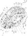
- FIG. 2 is a perspective view of the motor unit of one embodiment.
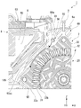
- FIG. 3 is a cross-sectional view of the motor unit of one embodiment.
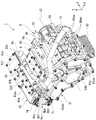
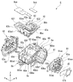
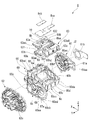
- FIG. 4 is an exploded perspective view of the housing of one embodiment.
- FIG. 5 is an exploded perspective view of the housing of one embodiment.
- FIG. 6 is a side view of the motor unit according to the embodiment as viewed from one axial side.
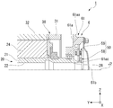
- FIG. 7 is a partial cross-sectional view of the motor unit of one embodiment.
- FIG. 8 is a perspective view of a motor unit having a modified closed portion.
- FIG. 9 is an enlarged perspective view of the inverter housing of the modified example.
- FIG. 10 is an exploded perspective view of the motor unit of one embodiment.
- FIG. 11 is a front view of the second bus bar unit arranged in the inverter chamber in the motor unit according to the embodiment.
- FIG. 12 is a partially enlarged view of FIG
- the motor axis J2 extends parallel to the vehicle. Therefore, in the following description, the axial direction is a direction parallel to the width direction of the vehicle. In this specification, one side in the axial direction is the ⁇ Y side, and the other side in the axial direction is the +Y side.
- extending along in a predetermined direction means not only a case of extending in a strictly predetermined direction but also an inclination of less than 45° with respect to the strict direction. Including the case of extending in the direction.
- FIG. 1 is a conceptual diagram schematically showing the motor unit 1.
- FIG. 2 is a perspective view of the motor unit 1.
- a storage space 80 for accommodating the motor 2, the gear portion 3, and the inverter 8 is provided inside the housing 6, a storage space 80 for accommodating the motor 2, the gear portion 3, and the inverter 8 is provided.
- the housing 6 holds the motor 2, the gear portion 3, and the inverter 8 in the accommodation space 80.
- the accommodation space 80 is divided into a motor chamber 81 that accommodates the motor 2, a gear chamber 82 that accommodates the gear unit 3, and an inverter chamber 83 that accommodates a part of the inverter 8 and a connecting wire.
- the motor chamber 81 is a storage space inside the motor storage portion 6a
- the gear chamber 82 is a storage space inside the gear storage portion 6b
- the inverter chamber 83 is an inverter space. It is a storage space inside the storage portion 6c.
- the motor 2 is housed in the motor chamber 81 of the housing 6.
- the motor 2 includes a rotor 20 that rotates about a motor axis J2 extending in the horizontal direction, a stator 30 that is located radially outside the rotor 20, a first bearing 26 that rotatably supports the rotor 20, and a second bearing 26. And a bearing 27.
- the motor 2 of this embodiment is an inner rotor type motor.
- the rotor core 24 is formed by stacking silicon steel plates.
- the rotor core 24 is a cylinder extending along the axial direction.
- a plurality of rotor magnets (not shown) are fixed to the rotor core 24.
- the plurality of rotor magnets are arranged along the circumferential direction with alternating magnetic poles.
- the stator 30 has a stator core 32, a coil 31, and an insulator (not shown) interposed between the stator core 32 and the coil 31.
- the stator 30 is held by the housing 6.
- the stator core 32 has an annular core back portion 32a and a plurality of teeth portions 32b extending radially inward from the core back portion 32a.
- a coil wire is wound around the tooth portion 32b.
- the coil wire hung on the teeth portion 32b constitutes the coil 31. That is, the coil 31 is wound around the stator core 32 via the insulator.
- the coil wire 31b extending from the coil 31 is connected to the inverter 8 via the first busbar unit 70 (see FIG. 6) and the second busbar unit 77 (via FIG. 9).
- the gear portion 3 is housed in the gear chamber 82 of the housing 6.
- the gear portion 3 is connected to the shaft 21 on the other axial side of the motor axis J2.
- the gear unit 3 has a speed reducing device 4 and a differential device 5.
- the torque output from the motor 2 is transmitted to the differential device 5 via the speed reducer 4.
- the speed reducer 4 is connected to the rotor 20 of the motor 2.
- the speed reducer 4 has a function of reducing the rotation speed of the motor 2 and increasing the torque output from the motor 2 according to the speed reduction ratio.
- the speed reducing device 4 transmits the torque output from the motor 2 to the differential device 5.
- the differential device 5 is connected to the motor 2 via the speed reducer 4.
- the differential device 5 is a device for transmitting the torque output from the motor 2 to the wheels of the vehicle.
- the differential device 5 has a function of transmitting the same torque to the output shafts 55 of the left and right wheels while absorbing the speed difference between the left and right wheels when the vehicle turns.
- the differential device 5 includes a ring gear 51, a gear housing (not shown), a pair of pinion gears (not shown), a pinion shaft (not shown), and a pair of side gears (not shown).
- the inverter 8 is electrically connected to the motor 2.
- the inverter 8 controls the current supplied to the motor 2.
- the inverter 8 is fixed to the inverter housing 63 of the housing 6.
- the inverter bus bar 8d extends from the switching element 8A.
- the inverter bus bar 8d is connected to a second bus bar 78, which will be described later, at the connection portion 8j.
- the housing 6 includes a housing body 60, a closing portion 61, a gear housing 62, and an inverter housing 63.
- the housing body 60 has a motor accommodating portion 6a, a gear accommodating portion 6b, and an inverter accommodating portion 6c. That is, the housing 6 has a motor accommodating portion 6a, a gear accommodating portion 6b, and an inverter accommodating portion 6c.
- the motor accommodating portion 6a opens on one side in the axial direction.
- the gear accommodating portion 6b opens on the other side in the axial direction.
- the inverter accommodating portion 6c opens upward.
- the closing portion 61, the gear housing 62, and the inverter housing 63 are fixed to the housing body 60.
- the housing body 60 and the closing portion 61 are arranged so as to face each other in the axial direction and are fixed to each other.
- the closing portion 61 covers the opening of the motor housing portion 6a of the housing body 60.
- the space surrounded by the housing body 60 and the closing portion 61 constitutes a motor chamber 81 in which the motor 2 is housed.
- the housing body 60 and the gear housing 62 are axially opposed to each other and fixed to each other.
- the gear housing 62 covers the opening of the gear housing portion 6b of the housing body 60.
- the space surrounded by the housing body 60 and the gear housing 62 constitutes a gear chamber 82 in which the gear portion 3 is housed.
- the housing body 60 and the inverter housing 63 are arranged facing each other in the vertical direction and fixed to each other.
- the inverter housing 63 covers the opening of the inverter housing portion 6c of the housing body 60.
- the space surrounded by the housing body 60 and the inverter housing 63 constitutes an inverter chamber 83 in which the inverter 8 is housed.
- the housing body 60 is a single member.
- the housing body 60 includes a tubular peripheral wall portion 60a extending in the axial direction, a plate-shaped first side plate portion 60b and a second side plate portion 60c extending along a plane orthogonal to the axial direction, and a plate extending along the axial direction.
- a first connecting plate portion 60d and a second connecting plate portion 60e each having a shape of a circle.
- the peripheral wall portion 60a has a cylindrical shape centered on the motor axis J2.
- the peripheral wall portion 60a surrounds the motor 2 from the outside in the radial direction.
- a first rib 60aa extending along the motor axis J2 and a second rib 60ab extending along the circumferential direction of the motor axis J2 are provided on the outer peripheral surface of the peripheral wall portion 60a. ..
- the first ribs 60aa and the second ribs 60ab can increase the rigidity of the housing body 60 and suppress amplification of vibration and noise caused by the rotation of the motor 2.
- the first rib 60aa may be used as a hot water drain wall when the housing body 60 is die-cast.
- the hot water drain wall is a joint portion between the molds for forming the housing body 60.
- a breather device 9 that adjusts the internal pressure of the motor chamber 81 is provided in an area facing the upper side of the outer peripheral surface of the peripheral wall portion 60a.
- the breather device 9 is preferably provided on the upper side of the housing 6.
- the signal line of the rotation angle sensor 50 that detects the rotation angle of the motor 2 passes through the second through hole 60bf.
- a sensor connector 73 is attached to the second through hole 60bf.
- the sensor connector 73 is inserted into the second through hole 60bf from one side in the axial direction. That is, the sensor connector 73 is attached to the second through hole 60bf from the motor chamber 81 side.
- a power supply line that connects the inverter 8 and the stator 30 and supplies a power supply voltage to the stator passes through the third through hole 60bg.
- the first bus bar unit 70 is inserted into the third through hole 60bg.
- the first bus bar unit 70 will be described in detail later.
- screw holes for fixing the first bus bar unit 70 to the first partition wall 60ba are provided around the third through hole.
- the first bus bar unit 70 is inserted into the third through hole 60bg from one axial side.
- first side plate portion 60b is provided with a motor side flange portion 60bc for fixing the closing portion 61.
- the motor side flange portion 60bc is provided with a plurality of screw holes for fixing the closing portion 61 to the housing body 60.
- the motor-side flange portion 60bc projects in the axial direction from the surfaces of the first partition wall 60ba and the first projecting portion 60bb that face one side in the axial direction.
- the second side plate portion 60c faces the first side plate portion 60b in the axial direction.
- the second side plate portion 60c is located at the other end (+Y side) in the axial direction of the peripheral wall portion 60a.
- the second side plate portion 60c is located on the other axial side of the inverter 8.
- the second side plate portion 60c covers the other axial side of the inverter 8.
- a plurality of ribs arranged along the axial direction are provided on the lower surface of the second connection plate portion 60e.
- the plurality of ribs extend from the peripheral wall portion 60a toward the rear side of the vehicle.
- the housing main body 60 includes the third partition wall (first wall portion) 60ac that partitions the inverter chamber 83 and the motor chamber 81, and the fourth partition wall partitioning the inverter chamber 83 and the gear chamber 82. (2nd wall part) 60ce.
- the third partition wall 60ac also serves as a side wall of the inverter housing portion 6c and the motor housing portion 6a.
- the fourth partition 60ce also serves as a side wall of the inverter housing portion 6c and the gear housing portion 6b. That is, according to the present embodiment, the inverter accommodating portion 6c is integrally provided with the motor accommodating portion 6a and the gear accommodating portion 6b, and thus is supported by the motor accommodating portion 6a and the gear accommodating portion 6b.
- the inverter housing portion 6c has a first side plate portion (third wall portion) 60b as a wall portion on one side in the axial direction.
- a closing portion 61 is fastened to the first side plate portion 60b.
- the inverter accommodating portion 6c is reinforced and rigidized by fastening the closing portion 61. That is, according to the present embodiment, the effect of suppressing the vibration of the inverter housing portion 6c can be further enhanced.
- the closing part 61 covers the sensor connector 73 and the first bus bar unit 70 fixed to the first partition wall 60ba of the housing body 60 shown in FIG.
- the closing portion 61 may have a function as a magnetic shield. At this time, it is possible to suppress that the wiring of the rotation angle sensor 50 and the noise generated in the first bus bar unit 70 affect the first connector 71 and the like.
- the closing portion main body 61a has a closing flat portion 61aa and a cover flange portion 61ab.
- the cover flange portion 61ab projects from the closed plane portion 61aa to the one side in the axial direction.
- a shaft insertion hole 61ac penetrating in the axial direction is provided in the closed flat surface portion 61aa.
- the shaft insertion hole 61ac is arranged inside the cover flange portion 61ab when viewed from the axial direction. Inside the shaft insertion hole 61ac, an end portion on one side in the axial direction of the shaft 21 of the motor 2 is arranged.
- the stator portion 59 of the rotation angle sensor 50 is fixed to the closing portion main body 61a so as to surround the rotor portion 58.
- the stator part 59 outputs a rotation angle relative to the rotor part 58. That is, the rotation angle sensor 50 detects the rotation angle of the motor 2.
- the rotation angle sensor 50 is a resolver.
- the rotation angle sensor 50 is attached in a state where the cover 61b is removed and one end of the shaft 21 on the one side in the axial direction is opened.
- the rigidity of the mounting part of the stator of the rotation angle sensor may be low, and the vibration of the gear may affect the detection accuracy of the rotation angle sensor.
- the motor unit 1 of the present embodiment is made to solve the problem.
- the housing 6 has the closing portion 61 that covers the opening on the one side in the axial direction of the motor housing portion 6a, and the closing portion 61 forms the sensor housing portion 61h that houses the rotation angle sensor 50 therein.
- the rotation angle sensor 50 is contained and fixed inside the closing portion 61, which is a structure having high rigidity. As a result, it is possible to suppress the transmission of vibration to the rotation angle sensor 50, and it is possible to improve the detection accuracy of the rotation angle sensor 50.
- the first pipe support portion 161e has a first pedestal portion 161ea and a binding band 161eb.
- the first pedestal portion 161ea is, for example, a resin member.
- the first pedestal portion 161ea is bolted to the surface of the closing portion body 161a facing the axial direction.
- the first pedestal portion 161ea is in contact with the cooling water pipe 11 on the seat surface facing one side in the axial direction.
- the seat surface is curved according to the pipe diameter of the cooling water pipe 11. This makes it difficult for the cooling water pipe 11 to shift with respect to the first pedestal portion 161ea.
- the first pedestal portion 161ea is provided with an insertion portion that allows the binding band 161eb to pass through.
- the closing portion 161 has the support portions (first and second pipe support portions 161e and 161f and the cable support portion 161d) that hold the cable 88 or the cooling water pipe 11.
- the cooling water pipe 11 and the cable 88 may be fixed to the closing part 161 in advance by the first and second pipe supporting parts 161e and 161f and the cable supporting part 161d. As a result, the assembly process can be simplified.
- the inverter housing 63 has a concave shape that opens downward due to the top plate portion 63ac and the side wall portion 63ad. That is, the inverter housing 63 has the inverter housing opening 63h.
- the inverter housing opening 63h is along the opening 6ca of the inverter housing portion 6c.
- at least a part of the inverter 8 is arranged so as to project downward from the inverter housing opening 63h. That is, the inverter accommodating portion 6c has a structure in which the openings of the concave member are opposed to each other and one opening closes the other opening, and the inverter 8 is arranged at the boundary between the openings 6ca and 63h. ing.
- the inverter accommodating portion 6c overlaps at least a part of the gear portion 3 when viewed in the axial direction. More specifically, the inverter accommodating portion 6c overlaps with the ring gear 51 of the gear portion 3 when viewed from the axial direction. That is, the inverter accommodating portion 6c can be disposed inside the axial projection area of the gear portion 3, and the axial projection size of the entire motor 2 can be reduced.
- the second bus bar 78 is made of a plate-shaped conductor.
- the three second bus bars 78 are connected to the U-phase, V-phase, and W-phase first bus bars 75, respectively.
- the second bus bar 78 is arranged in the inverter chamber 83.
- the second bus bar 78 is fixed to the outer peripheral surface of the peripheral wall portion 60 a of the housing body 60 via the second bus bar holder 79. More specifically, the second bus bar unit 77 is screw-fixed to the surface of the peripheral wall portion 60a facing the inverter chamber 83 side by using a plurality of fixing screws 77a.
- the first oil passage 91 and the second oil passage 92 include paths for moving the oil O from the lower region in the motor chamber 81 to the lower region in the gear chamber 82.
- (First oil passage) In the first oil passage 91, the oil O is lifted up from the oil sump P by the differential device 5 and introduced into the rotor 20. A centrifugal force is applied to the oil O inside the rotor 20 as the rotor 20 rotates. As a result, the oil O is evenly diffused toward the stator 30 that surrounds the rotor 20 from the radial outside, and cools the stator 30.
- the oil O can be used not only for cooling the motor 2 but also for lubricating each gear and each bearing of the gear unit 3. Since the oil O functions as a lubricating oil and a cooling oil, it is preferable to use the same oil as a lubricating oil for an automatic transmission (ATF: Automatic Transmission Fluid) having a low viscosity.
- ATF Automatic Transmission Fluid
- the second oil passage 92 has a first flow passage 92a, a second flow passage 92b, a third flow passage 92c, and a fourth flow passage 92d.
- a pump 96, a cooler 97, and an oil pipe (supply unit) 98 are provided in the route of the second oil passage 92.
- the pump 96 supplies the oil O to the motor 2.
- the cooler 97 cools the oil O passing through the second oil passage 92.
- the oil O is the oil O of the first flow path 92a, the pump 96, the second flow path 92b, the cooler 97, the third flow path 92c, the fourth flow path 92d, and the oil pipe 98. It passes through each part in order and is supplied to the motor 2.
- the first flow passage 92a, the second flow passage 92b, the third flow passage 92c, and the fourth flow passage 92d pass through the wall portion of the housing 6 that surrounds the accommodation space 80.
- the first flow path 92 a connects the oil reservoir P in the lower region of the accommodation space 80 and the pump 96.
- the second flow path 92b connects the pump 96 and the cooler 97.
- the third flow passage 92c connects the cooler 97 and the fourth flow passage 92d, and the fourth flow passage 92d connects the third flow passage 92c and the upper region of the accommodation space 80.
- the first flow passage 92a, the second flow passage 92b, the third flow passage 92c, and the fourth flow passage 92d pass through the inside of the wall portion of the housing 6 that surrounds the accommodation space 80. Therefore, it is not necessary to separately provide a pipe material when providing the flow path, which can contribute to a reduction in the number of parts.
- the cooler 97 is connected with a first flow path 92a and a second flow path 92b.
- the first flow path 92a and the second flow path 92b are connected via the internal flow path of the cooler 97.
- a cooling water pipe 11 through which cooling water W cooled by a radiator (not shown) passes is connected.
- the oil O passing through the inside of the cooler 97 is cooled by heat exchange with the cooling water W passing through the cooling water pipe 11. That is, according to the present embodiment, the cooler (heat exchanger) 97 that transfers the heat of the oil O to the cooling water W is provided.
- An inverter 8 is provided in the path of the cooling water pipe 11.
- the cooling water W that has cooled the inverter 8 passes through the cooling water pipe 11.
- the flow path 8b attached to the inverter housing 63 is connected to the cooling water pipe 11.
- the fourth flow path 92d passes through the inside of the wall portion of the motor accommodating portion 6a.
- the fourth flow path 92d opens in the motor chamber 81 and is connected to the oil pipe 98 at the opening.
- the fourth flow path 92d extends along the second partition wall 60ca of the housing body 60.
- the first ejection hole 98a extends along the axial direction. Further, the first ejection holes 98a are provided at both ends in the axial direction of the oil pipe 98. The first ejection hole 98a is located above the coil end 31a. The first ejection hole 98a faces the coil 31 and ejects oil into the coil 31.
- the second ejection hole 98b opposes the outer peripheral surface of the core back portion 32a and ejects oil to the outer peripheral surface.
- the oil O ejected from the second ejection hole 98b flows from the upper side to the lower side along the outer peripheral surface of the motor 2 and takes heat from the motor 2. As a result, the entire motor 2 is cooled.
- FIG. 12 shows the shielded flow path 195 of the modified example that can be adopted in the present embodiment by a broken line.
- the shielded flow path 195 of the modified example passes through the inside of the third partition wall 60ac that partitions the inverter chamber 83 and the motor chamber 81.
- the shielded flow path 195 of the modified example is adopted, the effect of shielding heat between the motor 2 and the inverter 8 can be enhanced as compared with the shielded flow path 95 of the embodiment.
- the water channel 10 is provided in the housing 6.
- the water channel 10 has a flow path 8 b that passes through the inside of the housing 6 and a cooling water pipe 11 that passes through the outside of the housing 6. Further, the cooler 97 is arranged in the water channel 10 as described above.
- the present embodiment describes a case where the oil O is used as the first refrigerant and the cooling water W is used as the second refrigerant, but the present invention is not limited to this.
- both the first refrigerant and the second refrigerant may be oil O, and even in this case, the first cooling path (oil passage 90) and the second cooling path (water passage 10) are It suffices that the oils provided in the mutually independent paths do not mix with each other.
Landscapes
- Engineering & Computer Science (AREA)
- Power Engineering (AREA)
- Transportation (AREA)
- Mechanical Engineering (AREA)
- Microelectronics & Electronic Packaging (AREA)
- Life Sciences & Earth Sciences (AREA)
- Sustainable Development (AREA)
- Sustainable Energy (AREA)
- Chemical & Material Sciences (AREA)
- Combustion & Propulsion (AREA)
- Motor Or Generator Frames (AREA)
- Motor Or Generator Cooling System (AREA)
- Connection Of Motors, Electrical Generators, Mechanical Devices, And The Like (AREA)
- Electric Propulsion And Braking For Vehicles (AREA)
- Arrangement Of Transmissions (AREA)
- Inverter Devices (AREA)
- Motor Power Transmission Devices (AREA)
- Hybrid Electric Vehicles (AREA)
Priority Applications (4)
| Application Number | Priority Date | Filing Date | Title |
|---|---|---|---|
| JP2021503437A JP7472897B2 (ja) | 2019-03-06 | 2020-01-10 | モータユニット |
| US17/436,584 US12040679B2 (en) | 2019-03-06 | 2020-01-10 | Motor unit |
| CN202080014534.3A CN113498573B (zh) | 2019-03-06 | 2020-01-10 | 马达单元 |
| DE112020001073.2T DE112020001073T5 (de) | 2019-03-06 | 2020-01-10 | Motoreinheit |
Applications Claiming Priority (6)
| Application Number | Priority Date | Filing Date | Title |
|---|---|---|---|
| JP2019040863 | 2019-03-06 | ||
| JP2019-040863 | 2019-03-06 | ||
| JP2019075237 | 2019-04-11 | ||
| JP2019-075237 | 2019-04-11 | ||
| JP2019110648 | 2019-06-13 | ||
| JP2019-110648 | 2019-06-13 |
Publications (1)
| Publication Number | Publication Date |
|---|---|
| WO2020179219A1 true WO2020179219A1 (ja) | 2020-09-10 |
Family
ID=72337249
Family Applications (4)
| Application Number | Title | Priority Date | Filing Date |
|---|---|---|---|
| PCT/JP2020/000653 Ceased WO2020179217A1 (ja) | 2019-03-06 | 2020-01-10 | モータユニット |
| PCT/JP2020/000654 Ceased WO2020179218A1 (ja) | 2019-03-06 | 2020-01-10 | モータユニット |
| PCT/JP2020/000655 Ceased WO2020179219A1 (ja) | 2019-03-06 | 2020-01-10 | モータユニット |
| PCT/JP2020/000652 Ceased WO2020179216A1 (ja) | 2019-03-06 | 2020-01-10 | モータユニット |
Family Applications Before (2)
| Application Number | Title | Priority Date | Filing Date |
|---|---|---|---|
| PCT/JP2020/000653 Ceased WO2020179217A1 (ja) | 2019-03-06 | 2020-01-10 | モータユニット |
| PCT/JP2020/000654 Ceased WO2020179218A1 (ja) | 2019-03-06 | 2020-01-10 | モータユニット |
Family Applications After (1)
| Application Number | Title | Priority Date | Filing Date |
|---|---|---|---|
| PCT/JP2020/000652 Ceased WO2020179216A1 (ja) | 2019-03-06 | 2020-01-10 | モータユニット |
Country Status (5)
| Country | Link |
|---|---|
| US (4) | US12040679B2 (enExample) |
| JP (4) | JP7439821B2 (enExample) |
| CN (4) | CN113498573B (enExample) |
| DE (4) | DE112020001077T5 (enExample) |
| WO (4) | WO2020179217A1 (enExample) |
Cited By (6)
| Publication number | Priority date | Publication date | Assignee | Title |
|---|---|---|---|---|
| JP2022081379A (ja) * | 2020-11-19 | 2022-05-31 | 日本電産株式会社 | 駆動装置、及び車両 |
| US20220224202A1 (en) * | 2021-01-13 | 2022-07-14 | Dana Belgium N.V. | Systems and methods for cooling electric motor |
| CN115051509A (zh) * | 2021-03-08 | 2022-09-13 | 日本电产株式会社 | 旋转电机及驱动装置 |
| CN115250030A (zh) * | 2021-04-26 | 2022-10-28 | 日本电产株式会社 | 驱动马达模块 |
| JP2023042978A (ja) * | 2021-09-15 | 2023-03-28 | 日本電産株式会社 | 駆動装置 |
| WO2023189033A1 (ja) * | 2022-03-31 | 2023-10-05 | ニデック株式会社 | 駆動装置 |
Families Citing this family (32)
| Publication number | Priority date | Publication date | Assignee | Title |
|---|---|---|---|---|
| EP3815944B1 (en) | 2019-10-31 | 2022-06-15 | BRUSA Elektronik AG | Compact powertrain with an electric motor |
| CN114901499B (zh) * | 2019-12-17 | 2025-09-16 | 日本电产株式会社 | 驱动装置 |
| JP7484552B2 (ja) * | 2020-08-12 | 2024-05-16 | ニデック株式会社 | 駆動装置 |
| EP4215778A4 (en) * | 2020-10-28 | 2024-03-20 | Aisin Corporation | Drive device for vehicle |
| JP7512861B2 (ja) | 2020-11-19 | 2024-07-09 | ニデック株式会社 | 駆動装置 |
| US20230327518A1 (en) * | 2020-11-25 | 2023-10-12 | Aisin Corporation | Rotary electric machine |
| DE102021214080A1 (de) * | 2020-12-25 | 2022-06-30 | Nidec Corporation | Antriebsvorrichtung |
| EP4253802B1 (en) * | 2020-12-30 | 2025-09-10 | Huawei Digital Power Technologies Co., Ltd. | Control method and device |
| JP7509048B2 (ja) * | 2021-02-02 | 2024-07-02 | トヨタ自動車株式会社 | 電動車両 |
| JP7468410B2 (ja) * | 2021-03-04 | 2024-04-16 | 株式会社アイシン | 回転電機 |
| US12489336B2 (en) * | 2021-03-31 | 2025-12-02 | Aisin Corporation | Vehicle drive device in which a power cable can appropriately be connected |
| JP7687853B2 (ja) * | 2021-04-28 | 2025-06-03 | 澤藤電機株式会社 | ステータおよびそのステータを備えた回転電機 |
| JP7668357B2 (ja) * | 2021-06-21 | 2025-04-24 | ヤマハ発動機株式会社 | モータおよびモータユニット |
| JP7766871B2 (ja) * | 2021-06-24 | 2025-11-11 | 株式会社エフ・シー・シー | 減速機付き電動機ユニット |
| JP7714390B2 (ja) * | 2021-06-30 | 2025-07-29 | ニデック株式会社 | モータユニット |
| JP2023025454A (ja) * | 2021-08-10 | 2023-02-22 | 日本電産株式会社 | 駆動装置 |
| JP2023031027A (ja) | 2021-08-24 | 2023-03-08 | 日本電産株式会社 | 駆動装置 |
| JP2023050914A (ja) * | 2021-09-30 | 2023-04-11 | 日本電産株式会社 | 電動パワーユニット |
| JP2023066956A (ja) * | 2021-10-29 | 2023-05-16 | ニデック株式会社 | 駆動装置 |
| WO2023095753A1 (ja) * | 2021-11-25 | 2023-06-01 | 株式会社アイシン | 車両用駆動装置 |
| DE102022103357B4 (de) * | 2022-02-14 | 2023-10-05 | Dr. Ing. H.C. F. Porsche Aktiengesellschaft | Kraftfahrzeug |
| DE102022113563A1 (de) | 2022-05-30 | 2023-11-30 | Dr. Ing. H.C. F. Porsche Aktiengesellschaft | Kühlsystem zur effektiven Kühlung einer elektrischen Maschine eines Kraftfahrzeugs |
| WO2023243314A1 (ja) * | 2022-06-15 | 2023-12-21 | ニデック株式会社 | 駆動装置 |
| EP4329166A1 (en) * | 2022-08-26 | 2024-02-28 | Valeo eAutomotive Germany GmbH | Arrangement, comprising an electric motor and an inverter and method for assembling the arrangement |
| CN115864715B (zh) * | 2022-12-08 | 2023-09-12 | 扬州大劲电机制造有限公司 | 一种长寿命耐久使用的电动工具用电机 |
| JPWO2024190154A1 (enExample) | 2023-03-14 | 2024-09-19 | ||
| DE102023108465A1 (de) * | 2023-04-03 | 2024-10-10 | Bayerische Motoren Werke Aktiengesellschaft | Antriebseinrichtung für ein Kraftfahrzeug, insbesondere für einen Kraftwagen, sowie Kraftfahrzeug mit wenigstens einer solchen Antriebseinrichtung |
| US20240405629A1 (en) * | 2023-06-01 | 2024-12-05 | Hamilton Sundstrand Corporation | Insulated actuator housing |
| WO2025062786A1 (ja) * | 2023-09-22 | 2025-03-27 | ジヤトコ株式会社 | ユニット |
| WO2025062785A1 (ja) * | 2023-09-22 | 2025-03-27 | ジヤトコ株式会社 | ユニット |
| DE102023212874A1 (de) * | 2023-12-18 | 2025-06-18 | Volkswagen Aktiengesellschaft | Elektrische Antriebseinheit für ein Kraftfahrzeug und Kraftfahrzeug |
| DE102024205552B3 (de) * | 2024-06-17 | 2025-05-22 | Zf Friedrichshafen Ag | Gehäuseteil |
Citations (10)
| Publication number | Priority date | Publication date | Assignee | Title |
|---|---|---|---|---|
| JP2001238406A (ja) * | 1999-04-27 | 2001-08-31 | Aisin Aw Co Ltd | 駆動装置 |
| JP2004260898A (ja) * | 2003-02-25 | 2004-09-16 | Nissan Motor Co Ltd | 電気自動車の駆動ユニット |
| JP2008092727A (ja) * | 2006-10-04 | 2008-04-17 | Toyota Motor Corp | 車両の駆動装置 |
| WO2015133229A1 (ja) * | 2014-03-03 | 2015-09-11 | コベルコ建機株式会社 | 電動機 |
| JP2016127732A (ja) * | 2015-01-06 | 2016-07-11 | 株式会社豊田自動織機 | スリップリング装置 |
| JP2017028798A (ja) * | 2015-07-17 | 2017-02-02 | 株式会社豊田自動織機 | 減速機付きモータの冷却構造 |
| JP2017127118A (ja) * | 2016-01-14 | 2017-07-20 | Ntn株式会社 | モータ用ハウジング |
| WO2018030322A1 (ja) * | 2016-08-09 | 2018-02-15 | 日本電産株式会社 | 駆動装置 |
| JP2018027003A (ja) * | 2016-08-09 | 2018-02-15 | 日本電産株式会社 | モータユニット |
| US20180287452A1 (en) * | 2017-03-28 | 2018-10-04 | Lg Electronics Inc. | Motor |
Family Cites Families (48)
| Publication number | Priority date | Publication date | Assignee | Title |
|---|---|---|---|---|
| JPH0769544B2 (ja) | 1987-01-23 | 1995-07-31 | 東レ株式会社 | 液晶素子および液晶素子配向膜用コーティング用組成物 |
| US4824803A (en) | 1987-06-22 | 1989-04-25 | Standard Microsystems Corporation | Multilayer metallization method for integrated circuits |
| JPH0826359B2 (ja) | 1987-09-30 | 1996-03-13 | 埼玉第一製薬株式会社 | ゲル状石鹸 |
| JP2600852B2 (ja) | 1987-10-12 | 1997-04-16 | セイコーエプソン株式会社 | 電気光学装置の駆動方法 |
| JPH0220385A (ja) | 1988-07-08 | 1990-01-23 | Kanzaki Paper Mfg Co Ltd | 感熱記録体 |
| JPH0766120B2 (ja) | 1989-05-09 | 1995-07-19 | セイコーエプソン株式会社 | 液晶表示装置 |
| JPH04863A (ja) | 1990-04-18 | 1992-01-06 | Canon Inc | 画像読取装置 |
| JPH075237A (ja) | 1993-06-16 | 1995-01-10 | Japan Radio Co Ltd | 航跡表示装置及び方法 |
| JP3886696B2 (ja) | 1999-04-27 | 2007-02-28 | アイシン・エィ・ダブリュ株式会社 | 駆動装置 |
| JP2001119898A (ja) | 1999-10-18 | 2001-04-27 | Aisin Aw Co Ltd | 駆動装置 |
| JP3893815B2 (ja) | 1999-10-18 | 2007-03-14 | アイシン・エィ・ダブリュ株式会社 | 車両駆動装置 |
| JP4477721B2 (ja) | 1999-11-15 | 2010-06-09 | 日本電産シバウラ株式会社 | ブラシレスdcモーター及びその製造方法 |
| JP3972170B2 (ja) * | 2000-09-26 | 2007-09-05 | スズキ株式会社 | 車両用モータアシスト装置の冷却構造 |
| JP4695287B2 (ja) * | 2001-04-27 | 2011-06-08 | 日本電産シンポ株式会社 | 回転駆動装置 |
| WO2004025808A1 (ja) * | 2002-09-13 | 2004-03-25 | Aisin Aw Co., Ltd. | 駆動装置 |
| JP4310683B2 (ja) * | 2003-05-13 | 2009-08-12 | アイシン・エィ・ダブリュ株式会社 | 電動機内蔵駆動装置 |
| JP4719134B2 (ja) * | 2006-11-22 | 2011-07-06 | 三菱重工業株式会社 | インバータ一体型電動圧縮機 |
| JP5051456B2 (ja) * | 2008-02-20 | 2012-10-17 | アイシン・エィ・ダブリュ株式会社 | ハイブリッド駆動装置 |
| JP2009303446A (ja) | 2008-06-17 | 2009-12-24 | Honda Motor Co Ltd | 永久磁石電動機 |
| JP5177232B2 (ja) | 2008-11-21 | 2013-04-03 | トヨタ自動車株式会社 | ブリーザ装置および駆動装置 |
| JP4951646B2 (ja) | 2009-03-26 | 2012-06-13 | 本田技研工業株式会社 | 端子台およびインバータケース |
| JP2011131828A (ja) * | 2009-12-25 | 2011-07-07 | Mitsubishi Fuso Truck & Bus Corp | ハイブリッド電気自動車のモータ用ベアリングの潤滑構造 |
| US20130046426A1 (en) * | 2010-05-18 | 2013-02-21 | Hiroyuki Tsukashima | Vehicle control system |
| JP5766431B2 (ja) * | 2010-11-30 | 2015-08-19 | 三菱重工業株式会社 | 電動圧縮機 |
| JP2012138989A (ja) * | 2010-12-24 | 2012-07-19 | Toyota Motor Corp | 動力伝達装置 |
| JP6014599B2 (ja) * | 2011-11-09 | 2016-10-25 | 日立オートモティブシステムズ株式会社 | 電気自動車の駆動装置 |
| JP5464224B2 (ja) | 2012-03-14 | 2014-04-09 | 株式会社安川電機 | モータ駆動装置および車両 |
| JP5655873B2 (ja) * | 2012-05-09 | 2015-01-21 | 株式会社安川電機 | インバータ装置 |
| JP5862502B2 (ja) * | 2012-07-27 | 2016-02-16 | アイシン・エィ・ダブリュ株式会社 | 車両用駆動装置 |
| JP5978954B2 (ja) | 2012-11-26 | 2016-08-24 | 三菱自動車工業株式会社 | 回転電機装置 |
| JP6245075B2 (ja) * | 2014-05-28 | 2017-12-13 | アイシン・エィ・ダブリュ株式会社 | 車両用駆動装置 |
| JP6442922B2 (ja) * | 2014-08-22 | 2018-12-26 | 日本電産株式会社 | モータ |
| JP6441642B2 (ja) * | 2014-10-31 | 2018-12-19 | 株式会社安川電機 | 駆動装置及びそれを備える乗り物並びに駆動装置の製造方法 |
| JP6573456B2 (ja) * | 2015-01-28 | 2019-09-11 | 本田技研工業株式会社 | 一体型ユニット |
| JP6435972B2 (ja) | 2015-04-06 | 2018-12-12 | トヨタ自動車株式会社 | 動力伝達装置 |
| JP6876366B2 (ja) * | 2015-05-20 | 2021-05-26 | 日産自動車株式会社 | 車載駆動装置 |
| JP6593625B2 (ja) * | 2015-05-25 | 2019-10-23 | 株式会社ジェイテクト | 回転角検出装置 |
| WO2017033917A1 (ja) * | 2015-08-27 | 2017-03-02 | 日本電産株式会社 | モータ |
| JP6844540B2 (ja) * | 2015-11-06 | 2021-03-17 | 日本電産株式会社 | モータ |
| WO2017217495A1 (ja) * | 2016-06-17 | 2017-12-21 | 株式会社ミツバ | 減速機付モータおよび減速機付モータの組立方法 |
| WO2018030218A1 (ja) | 2016-08-09 | 2018-02-15 | 日本電産株式会社 | モータ |
| JP6492127B2 (ja) * | 2016-08-11 | 2019-03-27 | ハンオン システムズ | インバータ一体型bldcモータ |
| JP2018046713A (ja) * | 2016-09-16 | 2018-03-22 | 日本電産株式会社 | モータ |
| JP6785691B2 (ja) | 2017-03-13 | 2020-11-18 | 住友重機械工業株式会社 | 駆動装置 |
| CN110999040B (zh) * | 2017-07-28 | 2022-02-01 | 日本电产株式会社 | 马达 |
| JP7040770B2 (ja) | 2017-08-23 | 2022-03-23 | 国立大学法人東北大学 | 活性種含有液噴射装置 |
| JP7008262B2 (ja) | 2017-10-13 | 2022-01-25 | トヨタ自動車株式会社 | リチウムイオン二次電池用電極およびリチウムイオン二次電池 |
| JP6644443B2 (ja) | 2017-12-16 | 2020-02-12 | 株式会社アーズ | 切換装置、それを備える電力ユニットおよびそれを備える電力システム |
-
2020
- 2020-01-10 US US17/436,584 patent/US12040679B2/en active Active
- 2020-01-10 DE DE112020001077.5T patent/DE112020001077T5/de active Pending
- 2020-01-10 JP JP2021503436A patent/JP7439821B2/ja active Active
- 2020-01-10 CN CN202080014534.3A patent/CN113498573B/zh active Active
- 2020-01-10 DE DE112020001076.7T patent/DE112020001076T5/de active Pending
- 2020-01-10 US US17/436,587 patent/US11996756B2/en active Active
- 2020-01-10 CN CN202080014496.1A patent/CN113424417B/zh active Active
- 2020-01-10 DE DE112020001073.2T patent/DE112020001073T5/de active Pending
- 2020-01-10 CN CN202080014504.2A patent/CN113424418B/zh active Active
- 2020-01-10 DE DE112020001070.8T patent/DE112020001070T5/de active Pending
- 2020-01-10 US US17/436,585 patent/US12027946B2/en active Active
- 2020-01-10 JP JP2021503434A patent/JP7439819B2/ja active Active
- 2020-01-10 JP JP2021503435A patent/JP7439820B2/ja active Active
- 2020-01-10 WO PCT/JP2020/000653 patent/WO2020179217A1/ja not_active Ceased
- 2020-01-10 CN CN202080014557.4A patent/CN113424419B/zh active Active
- 2020-01-10 JP JP2021503437A patent/JP7472897B2/ja active Active
- 2020-01-10 WO PCT/JP2020/000654 patent/WO2020179218A1/ja not_active Ceased
- 2020-01-10 US US17/431,425 patent/US20220123628A1/en not_active Abandoned
- 2020-01-10 WO PCT/JP2020/000655 patent/WO2020179219A1/ja not_active Ceased
- 2020-01-10 WO PCT/JP2020/000652 patent/WO2020179216A1/ja not_active Ceased
Patent Citations (10)
| Publication number | Priority date | Publication date | Assignee | Title |
|---|---|---|---|---|
| JP2001238406A (ja) * | 1999-04-27 | 2001-08-31 | Aisin Aw Co Ltd | 駆動装置 |
| JP2004260898A (ja) * | 2003-02-25 | 2004-09-16 | Nissan Motor Co Ltd | 電気自動車の駆動ユニット |
| JP2008092727A (ja) * | 2006-10-04 | 2008-04-17 | Toyota Motor Corp | 車両の駆動装置 |
| WO2015133229A1 (ja) * | 2014-03-03 | 2015-09-11 | コベルコ建機株式会社 | 電動機 |
| JP2016127732A (ja) * | 2015-01-06 | 2016-07-11 | 株式会社豊田自動織機 | スリップリング装置 |
| JP2017028798A (ja) * | 2015-07-17 | 2017-02-02 | 株式会社豊田自動織機 | 減速機付きモータの冷却構造 |
| JP2017127118A (ja) * | 2016-01-14 | 2017-07-20 | Ntn株式会社 | モータ用ハウジング |
| WO2018030322A1 (ja) * | 2016-08-09 | 2018-02-15 | 日本電産株式会社 | 駆動装置 |
| JP2018027003A (ja) * | 2016-08-09 | 2018-02-15 | 日本電産株式会社 | モータユニット |
| US20180287452A1 (en) * | 2017-03-28 | 2018-10-04 | Lg Electronics Inc. | Motor |
Cited By (12)
| Publication number | Priority date | Publication date | Assignee | Title |
|---|---|---|---|---|
| JP2022081379A (ja) * | 2020-11-19 | 2022-05-31 | 日本電産株式会社 | 駆動装置、及び車両 |
| JP7647276B2 (ja) | 2020-11-19 | 2025-03-18 | ニデック株式会社 | 駆動装置、及び車両 |
| US20220224202A1 (en) * | 2021-01-13 | 2022-07-14 | Dana Belgium N.V. | Systems and methods for cooling electric motor |
| US11722038B2 (en) * | 2021-01-13 | 2023-08-08 | Dana Belgium N.V. | Systems and methods for cooling electric motor |
| US12355337B2 (en) | 2021-01-13 | 2025-07-08 | Dana Belgium N.V. | Systems and methods for cooling electric motor |
| CN115051509A (zh) * | 2021-03-08 | 2022-09-13 | 日本电产株式会社 | 旋转电机及驱动装置 |
| JP2022136836A (ja) * | 2021-03-08 | 2022-09-21 | 日本電産株式会社 | 回転電機、および駆動装置 |
| JP7647181B2 (ja) | 2021-03-08 | 2025-03-18 | ニデック株式会社 | 回転電機、および駆動装置 |
| CN115250030A (zh) * | 2021-04-26 | 2022-10-28 | 日本电产株式会社 | 驱动马达模块 |
| JP2022168575A (ja) * | 2021-04-26 | 2022-11-08 | 日本電産株式会社 | 駆動モータモジュール |
| JP2023042978A (ja) * | 2021-09-15 | 2023-03-28 | 日本電産株式会社 | 駆動装置 |
| WO2023189033A1 (ja) * | 2022-03-31 | 2023-10-05 | ニデック株式会社 | 駆動装置 |
Also Published As
| Publication number | Publication date |
|---|---|
| US20220173638A1 (en) | 2022-06-02 |
| CN113424417A (zh) | 2021-09-21 |
| US20220123628A1 (en) | 2022-04-21 |
| US12027946B2 (en) | 2024-07-02 |
| JPWO2020179219A1 (enExample) | 2020-09-10 |
| JPWO2020179218A1 (enExample) | 2020-09-10 |
| CN113424418A (zh) | 2021-09-21 |
| CN113424419B (zh) | 2024-07-26 |
| CN113498573B (zh) | 2024-07-26 |
| US12040679B2 (en) | 2024-07-16 |
| JP7439820B2 (ja) | 2024-02-28 |
| JP7472897B2 (ja) | 2024-04-23 |
| DE112020001070T5 (de) | 2021-12-09 |
| WO2020179217A1 (ja) | 2020-09-10 |
| CN113424418B (zh) | 2024-07-19 |
| JP7439821B2 (ja) | 2024-02-28 |
| US20220173639A1 (en) | 2022-06-02 |
| CN113424419A (zh) | 2021-09-21 |
| JP7439819B2 (ja) | 2024-02-28 |
| JPWO2020179217A1 (enExample) | 2020-09-10 |
| JPWO2020179216A1 (enExample) | 2020-09-10 |
| WO2020179218A1 (ja) | 2020-09-10 |
| US11996756B2 (en) | 2024-05-28 |
| DE112020001073T5 (de) | 2021-12-23 |
| CN113424417B (zh) | 2024-08-23 |
| CN113498573A (zh) | 2021-10-12 |
| DE112020001076T5 (de) | 2021-12-09 |
| WO2020179216A1 (ja) | 2020-09-10 |
| DE112020001077T5 (de) | 2021-12-09 |
| US20220149701A1 (en) | 2022-05-12 |
Similar Documents
| Publication | Publication Date | Title |
|---|---|---|
| JP7439820B2 (ja) | モータユニット | |
| JP7559752B2 (ja) | モータユニット | |
| JP7613542B2 (ja) | モータユニット | |
| JP7400365B2 (ja) | モータユニット | |
| CN114930695B (zh) | 马达单元 | |
| WO2020066955A1 (ja) | 駆動装置 | |
| WO2019131421A1 (ja) | モータユニット | |
| WO2021166298A1 (ja) | モータユニット | |
| JP2022136836A (ja) | 回転電機、および駆動装置 | |
| JP2022128993A (ja) | 回転電機および駆動装置 | |
| US20230027341A1 (en) | Rotating electric machine and drive apparatus | |
| WO2019131420A1 (ja) | モータユニット、およびモータユニットの製造方法 | |
| JP2022081344A (ja) | 駆動装置 | |
| WO2021166302A1 (ja) | モータユニットおよびモータユニットの製造方法 | |
| TWI814089B (zh) | 馬達單元 | |
| WO2023243314A1 (ja) | 駆動装置 | |
| WO2024143510A1 (ja) | 駆動装置 |
Legal Events
| Date | Code | Title | Description |
|---|---|---|---|
| 121 | Ep: the epo has been informed by wipo that ep was designated in this application |
Ref document number: 20767091 Country of ref document: EP Kind code of ref document: A1 |
|
| ENP | Entry into the national phase |
Ref document number: 2021503437 Country of ref document: JP Kind code of ref document: A |
|
| 122 | Ep: pct application non-entry in european phase |
Ref document number: 20767091 Country of ref document: EP Kind code of ref document: A1 |