WO2020122023A1 - 投映像表示用部材、ウインドシールドガラスおよびヘッドアップディスプレイシステム - Google Patents
投映像表示用部材、ウインドシールドガラスおよびヘッドアップディスプレイシステム Download PDFInfo
- Publication number
- WO2020122023A1 WO2020122023A1 PCT/JP2019/048114 JP2019048114W WO2020122023A1 WO 2020122023 A1 WO2020122023 A1 WO 2020122023A1 JP 2019048114 W JP2019048114 W JP 2019048114W WO 2020122023 A1 WO2020122023 A1 WO 2020122023A1
- Authority
- WO
- WIPO (PCT)
- Prior art keywords
- layer
- light
- liquid crystal
- polarization conversion
- image display
- Prior art date
Links
- 239000011521 glass Substances 0.000 title claims abstract description 218
- 230000010287 polarization Effects 0.000 claims abstract description 156
- 238000006243 chemical reaction Methods 0.000 claims abstract description 133
- 239000004973 liquid crystal related substance Substances 0.000 claims abstract description 89
- 150000001875 compounds Chemical class 0.000 claims abstract description 82
- 230000014509 gene expression Effects 0.000 claims description 6
- 230000001678 irradiating effect Effects 0.000 claims description 2
- 239000011295 pitch Substances 0.000 abstract description 33
- 239000010410 layer Substances 0.000 description 398
- 239000010408 film Substances 0.000 description 121
- 239000004986 Cholesteric liquid crystals (ChLC) Substances 0.000 description 120
- 238000000034 method Methods 0.000 description 51
- 238000000576 coating method Methods 0.000 description 43
- 239000011248 coating agent Substances 0.000 description 42
- 239000000203 mixture Substances 0.000 description 40
- 238000002834 transmittance Methods 0.000 description 39
- 239000005340 laminated glass Substances 0.000 description 35
- 239000007788 liquid Substances 0.000 description 35
- 239000012790 adhesive layer Substances 0.000 description 32
- 239000011229 interlayer Substances 0.000 description 27
- 230000003287 optical effect Effects 0.000 description 27
- UWCWUCKPEYNDNV-LBPRGKRZSA-N 2,6-dimethyl-n-[[(2s)-pyrrolidin-2-yl]methyl]aniline Chemical compound CC1=CC=CC(C)=C1NC[C@H]1NCCC1 UWCWUCKPEYNDNV-LBPRGKRZSA-N 0.000 description 24
- 238000011156 evaluation Methods 0.000 description 21
- 239000000853 adhesive Substances 0.000 description 20
- 230000001070 adhesive effect Effects 0.000 description 20
- 125000004432 carbon atom Chemical group C* 0.000 description 20
- 239000000463 material Substances 0.000 description 20
- 230000000052 comparative effect Effects 0.000 description 19
- 239000003795 chemical substances by application Substances 0.000 description 18
- 125000001424 substituent group Chemical group 0.000 description 17
- -1 cyanobiphenyls Chemical group 0.000 description 14
- 229920002037 poly(vinyl butyral) polymer Polymers 0.000 description 13
- 125000002947 alkylene group Chemical group 0.000 description 11
- 238000001723 curing Methods 0.000 description 11
- 229920002678 cellulose Polymers 0.000 description 10
- 239000001913 cellulose Substances 0.000 description 10
- 239000003505 polymerization initiator Substances 0.000 description 10
- 238000006116 polymerization reaction Methods 0.000 description 10
- 229920005989 resin Polymers 0.000 description 10
- 239000011347 resin Substances 0.000 description 10
- 239000002904 solvent Substances 0.000 description 10
- ODIGIKRIUKFKHP-UHFFFAOYSA-N (n-propan-2-yloxycarbonylanilino) acetate Chemical compound CC(C)OC(=O)N(OC(C)=O)C1=CC=CC=C1 ODIGIKRIUKFKHP-UHFFFAOYSA-N 0.000 description 9
- ZWEHNKRNPOVVGH-UHFFFAOYSA-N 2-Butanone Chemical compound CCC(C)=O ZWEHNKRNPOVVGH-UHFFFAOYSA-N 0.000 description 9
- 238000010438 heat treatment Methods 0.000 description 9
- 238000004519 manufacturing process Methods 0.000 description 9
- 239000004372 Polyvinyl alcohol Substances 0.000 description 8
- 125000000217 alkyl group Chemical group 0.000 description 8
- 230000015572 biosynthetic process Effects 0.000 description 8
- 229910052799 carbon Inorganic materials 0.000 description 8
- 239000003431 cross linking reagent Substances 0.000 description 8
- 229910052731 fluorine Inorganic materials 0.000 description 8
- 229920002451 polyvinyl alcohol Polymers 0.000 description 8
- 125000005407 trans-1,4-cyclohexylene group Chemical group [H]C1([H])C([H])([H])[C@]([H])([*:2])C([H])([H])C([H])([H])[C@@]1([H])[*:1] 0.000 description 8
- NIXOWILDQLNWCW-UHFFFAOYSA-M Acrylate Chemical compound [O-]C(=O)C=C NIXOWILDQLNWCW-UHFFFAOYSA-M 0.000 description 7
- YCKRFDGAMUMZLT-UHFFFAOYSA-N Fluorine atom Chemical compound [F] YCKRFDGAMUMZLT-UHFFFAOYSA-N 0.000 description 7
- 239000011737 fluorine Substances 0.000 description 7
- 125000005647 linker group Chemical group 0.000 description 7
- 230000008859 change Effects 0.000 description 6
- 125000000753 cycloalkyl group Chemical group 0.000 description 6
- 238000010586 diagram Methods 0.000 description 6
- 238000010030 laminating Methods 0.000 description 6
- 238000003475 lamination Methods 0.000 description 6
- 238000005259 measurement Methods 0.000 description 6
- 125000000843 phenylene group Chemical group C1(=C(C=CC=C1)*)* 0.000 description 6
- 239000010409 thin film Substances 0.000 description 6
- 230000005540 biological transmission Effects 0.000 description 5
- 229920002647 polyamide Polymers 0.000 description 5
- 238000001228 spectrum Methods 0.000 description 5
- 238000012546 transfer Methods 0.000 description 5
- 230000003098 cholesteric effect Effects 0.000 description 4
- 238000005520 cutting process Methods 0.000 description 4
- 125000004435 hydrogen atom Chemical group [H]* 0.000 description 4
- 238000003384 imaging method Methods 0.000 description 4
- 238000000016 photochemical curing Methods 0.000 description 4
- 229920000642 polymer Polymers 0.000 description 4
- KCTAWXVAICEBSD-UHFFFAOYSA-N prop-2-enoyloxy prop-2-eneperoxoate Chemical compound C=CC(=O)OOOC(=O)C=C KCTAWXVAICEBSD-UHFFFAOYSA-N 0.000 description 4
- 239000000758 substrate Substances 0.000 description 4
- 239000004094 surface-active agent Substances 0.000 description 4
- OKKJLVBELUTLKV-UHFFFAOYSA-N Methanol Chemical compound OC OKKJLVBELUTLKV-UHFFFAOYSA-N 0.000 description 3
- 239000004952 Polyamide Substances 0.000 description 3
- 239000004642 Polyimide Substances 0.000 description 3
- 125000003545 alkoxy group Chemical group 0.000 description 3
- QVGXLLKOCUKJST-UHFFFAOYSA-N atomic oxygen Chemical compound [O] QVGXLLKOCUKJST-UHFFFAOYSA-N 0.000 description 3
- 229910052801 chlorine Inorganic materials 0.000 description 3
- 238000001035 drying Methods 0.000 description 3
- 230000000694 effects Effects 0.000 description 3
- 230000005684 electric field Effects 0.000 description 3
- 239000005038 ethylene vinyl acetate Substances 0.000 description 3
- 230000004927 fusion Effects 0.000 description 3
- 230000004313 glare Effects 0.000 description 3
- 230000001965 increasing effect Effects 0.000 description 3
- 239000003999 initiator Substances 0.000 description 3
- 239000001301 oxygen Substances 0.000 description 3
- 229910052760 oxygen Inorganic materials 0.000 description 3
- 238000005498 polishing Methods 0.000 description 3
- 229920001200 poly(ethylene-vinyl acetate) Polymers 0.000 description 3
- 229920000139 polyethylene terephthalate Polymers 0.000 description 3
- 239000005020 polyethylene terephthalate Substances 0.000 description 3
- 229920001721 polyimide Polymers 0.000 description 3
- 229920000098 polyolefin Polymers 0.000 description 3
- XLYOFNOQVPJJNP-UHFFFAOYSA-N water Substances O XLYOFNOQVPJJNP-UHFFFAOYSA-N 0.000 description 3
- HXNBAOLVPAWYLT-NVNXTCNLSA-N (5z)-5-[[5-bromo-2-[(2-bromophenyl)methoxy]phenyl]methylidene]-2-sulfanylidene-1,3-thiazolidin-4-one Chemical compound S\1C(=S)NC(=O)C/1=C/C1=CC(Br)=CC=C1OCC1=CC=CC=C1Br HXNBAOLVPAWYLT-NVNXTCNLSA-N 0.000 description 2
- ZTQSAGDEMFDKMZ-UHFFFAOYSA-N Butyraldehyde Chemical compound CCCC=O ZTQSAGDEMFDKMZ-UHFFFAOYSA-N 0.000 description 2
- ZAMOUSCENKQFHK-UHFFFAOYSA-N Chlorine atom Chemical compound [Cl] ZAMOUSCENKQFHK-UHFFFAOYSA-N 0.000 description 2
- 229920001651 Cyanoacrylate Polymers 0.000 description 2
- 229920000219 Ethylene vinyl alcohol Polymers 0.000 description 2
- KLDXJTOLSGUMSJ-JGWLITMVSA-N Isosorbide Chemical class O[C@@H]1CO[C@@H]2[C@@H](O)CO[C@@H]21 KLDXJTOLSGUMSJ-JGWLITMVSA-N 0.000 description 2
- MWCLLHOVUTZFKS-UHFFFAOYSA-N Methyl cyanoacrylate Chemical compound COC(=O)C(=C)C#N MWCLLHOVUTZFKS-UHFFFAOYSA-N 0.000 description 2
- 239000004988 Nematic liquid crystal Substances 0.000 description 2
- 239000004743 Polypropylene Substances 0.000 description 2
- 239000004793 Polystyrene Substances 0.000 description 2
- 239000004820 Pressure-sensitive adhesive Substances 0.000 description 2
- 102100024599 Protein tyrosine phosphatase type IVA 1 Human genes 0.000 description 2
- 101710138644 Protein tyrosine phosphatase type IVA 1 Proteins 0.000 description 2
- 102100024602 Protein tyrosine phosphatase type IVA 2 Human genes 0.000 description 2
- 101710138646 Protein tyrosine phosphatase type IVA 2 Proteins 0.000 description 2
- 102100024601 Protein tyrosine phosphatase type IVA 3 Human genes 0.000 description 2
- 101710138647 Protein tyrosine phosphatase type IVA 3 Proteins 0.000 description 2
- BZHJMEDXRYGGRV-UHFFFAOYSA-N Vinyl chloride Chemical compound ClC=C BZHJMEDXRYGGRV-UHFFFAOYSA-N 0.000 description 2
- DZBUGLKDJFMEHC-UHFFFAOYSA-N acridine Chemical compound C1=CC=CC2=CC3=CC=CC=C3N=C21 DZBUGLKDJFMEHC-UHFFFAOYSA-N 0.000 description 2
- 150000001252 acrylic acid derivatives Chemical class 0.000 description 2
- 239000000654 additive Substances 0.000 description 2
- 150000001336 alkenes Chemical class 0.000 description 2
- 125000004069 aziridinyl group Chemical group 0.000 description 2
- ZDZHCHYQNPQSGG-UHFFFAOYSA-N binaphthyl group Chemical group C1(=CC=CC2=CC=CC=C12)C1=CC=CC2=CC=CC=C12 ZDZHCHYQNPQSGG-UHFFFAOYSA-N 0.000 description 2
- 239000000460 chlorine Substances 0.000 description 2
- KRKNYBCHXYNGOX-UHFFFAOYSA-N citric acid Natural products OC(=O)CC(O)(C(O)=O)CC(O)=O KRKNYBCHXYNGOX-UHFFFAOYSA-N 0.000 description 2
- 239000011247 coating layer Substances 0.000 description 2
- 239000003086 colorant Substances 0.000 description 2
- 238000000295 emission spectrum Methods 0.000 description 2
- 125000003700 epoxy group Chemical group 0.000 description 2
- UHESRSKEBRADOO-UHFFFAOYSA-N ethyl carbamate;prop-2-enoic acid Chemical compound OC(=O)C=C.CCOC(N)=O UHESRSKEBRADOO-UHFFFAOYSA-N 0.000 description 2
- 239000004715 ethylene vinyl alcohol Substances 0.000 description 2
- 239000004744 fabric Substances 0.000 description 2
- 230000005484 gravity Effects 0.000 description 2
- 238000007756 gravure coating Methods 0.000 description 2
- 125000005843 halogen group Chemical group 0.000 description 2
- 238000013007 heat curing Methods 0.000 description 2
- RZXDTJIXPSCHCI-UHFFFAOYSA-N hexa-1,5-diene-2,5-diol Chemical compound OC(=C)CCC(O)=C RZXDTJIXPSCHCI-UHFFFAOYSA-N 0.000 description 2
- 239000012943 hotmelt Substances 0.000 description 2
- 230000001771 impaired effect Effects 0.000 description 2
- 230000006872 improvement Effects 0.000 description 2
- 239000012948 isocyanate Substances 0.000 description 2
- 150000002576 ketones Chemical class 0.000 description 2
- 125000002496 methyl group Chemical group [H]C([H])([H])* 0.000 description 2
- JRZJOMJEPLMPRA-UHFFFAOYSA-N olefin Natural products CCCCCCCC=C JRZJOMJEPLMPRA-UHFFFAOYSA-N 0.000 description 2
- 150000002894 organic compounds Chemical class 0.000 description 2
- 239000003960 organic solvent Substances 0.000 description 2
- 239000002985 plastic film Substances 0.000 description 2
- 229920006255 plastic film Polymers 0.000 description 2
- 229920001084 poly(chloroprene) Polymers 0.000 description 2
- 229920000728 polyester Polymers 0.000 description 2
- 230000000379 polymerizing effect Effects 0.000 description 2
- 229920001155 polypropylene Polymers 0.000 description 2
- 229920002223 polystyrene Polymers 0.000 description 2
- 229920002635 polyurethane Polymers 0.000 description 2
- 239000004814 polyurethane Substances 0.000 description 2
- KWYUFKZDYYNOTN-UHFFFAOYSA-M potassium hydroxide Inorganic materials [OH-].[K+] KWYUFKZDYYNOTN-UHFFFAOYSA-M 0.000 description 2
- 238000012545 processing Methods 0.000 description 2
- 238000000985 reflectance spectrum Methods 0.000 description 2
- 239000005336 safety glass Substances 0.000 description 2
- 238000007127 saponification reaction Methods 0.000 description 2
- 239000002356 single layer Substances 0.000 description 2
- 239000007787 solid Substances 0.000 description 2
- 238000010998 test method Methods 0.000 description 2
- 125000003718 tetrahydrofuranyl group Chemical group 0.000 description 2
- 238000009281 ultraviolet germicidal irradiation Methods 0.000 description 2
- 230000000007 visual effect Effects 0.000 description 2
- KLDXJTOLSGUMSJ-BXKVDMCESA-N (3s,3as,6s,6as)-2,3,3a,5,6,6a-hexahydrofuro[3,2-b]furan-3,6-diol Chemical class O[C@H]1CO[C@H]2[C@@H](O)CO[C@H]21 KLDXJTOLSGUMSJ-BXKVDMCESA-N 0.000 description 1
- 125000001140 1,4-phenylene group Chemical group [H]C1=C([H])C([*:2])=C([H])C([H])=C1[*:1] 0.000 description 1
- UWFRVQVNYNPBEF-UHFFFAOYSA-N 1-(2,4-dimethylphenyl)propan-1-one Chemical compound CCC(=O)C1=CC=C(C)C=C1C UWFRVQVNYNPBEF-UHFFFAOYSA-N 0.000 description 1
- AUXIEQKHXAYAHG-UHFFFAOYSA-N 1-phenylcyclohexane-1-carbonitrile Chemical class C=1C=CC=CC=1C1(C#N)CCCCC1 AUXIEQKHXAYAHG-UHFFFAOYSA-N 0.000 description 1
- OOLUVSIJOMLOCB-UHFFFAOYSA-N 1633-22-3 Chemical compound C1CC(C=C2)=CC=C2CCC2=CC=C1C=C2 OOLUVSIJOMLOCB-UHFFFAOYSA-N 0.000 description 1
- GJKGAPPUXSSCFI-UHFFFAOYSA-N 2-Hydroxy-4'-(2-hydroxyethoxy)-2-methylpropiophenone Chemical compound CC(C)(O)C(=O)C1=CC=C(OCCO)C=C1 GJKGAPPUXSSCFI-UHFFFAOYSA-N 0.000 description 1
- 125000003504 2-oxazolinyl group Chemical group O1C(=NCC1)* 0.000 description 1
- WLNDDIWESXCXHM-UHFFFAOYSA-N 2-phenyl-1,4-dioxane Chemical compound C1OCCOC1C1=CC=CC=C1 WLNDDIWESXCXHM-UHFFFAOYSA-N 0.000 description 1
- OXPDQFOKSZYEMJ-UHFFFAOYSA-N 2-phenylpyrimidine Chemical class C1=CC=CC=C1C1=NC=CC=N1 OXPDQFOKSZYEMJ-UHFFFAOYSA-N 0.000 description 1
- UWHCZFSSKUSDNV-UHFFFAOYSA-N 3-(aziridin-1-yl)propanoic acid;2-ethyl-2-(hydroxymethyl)propane-1,3-diol Chemical compound OC(=O)CCN1CC1.OC(=O)CCN1CC1.OC(=O)CCN1CC1.CCC(CO)(CO)CO UWHCZFSSKUSDNV-UHFFFAOYSA-N 0.000 description 1
- ZCYVEMRRCGMTRW-UHFFFAOYSA-N 7553-56-2 Chemical group [I] ZCYVEMRRCGMTRW-UHFFFAOYSA-N 0.000 description 1
- 229920000178 Acrylic resin Polymers 0.000 description 1
- 239000004925 Acrylic resin Substances 0.000 description 1
- WKBOTKDWSSQWDR-UHFFFAOYSA-N Bromine atom Chemical group [Br] WKBOTKDWSSQWDR-UHFFFAOYSA-N 0.000 description 1
- 229920001634 Copolyester Polymers 0.000 description 1
- 239000004985 Discotic Liquid Crystal Substance Substances 0.000 description 1
- 239000004593 Epoxy Substances 0.000 description 1
- 239000005057 Hexamethylene diisocyanate Substances 0.000 description 1
- CERQOIWHTDAKMF-UHFFFAOYSA-M Methacrylate Chemical compound CC(=C)C([O-])=O CERQOIWHTDAKMF-UHFFFAOYSA-M 0.000 description 1
- 239000004962 Polyamide-imide Substances 0.000 description 1
- 239000004697 Polyetherimide Substances 0.000 description 1
- 229920000297 Rayon Polymers 0.000 description 1
- ZJCCRDAZUWHFQH-UHFFFAOYSA-N Trimethylolpropane Chemical compound CCC(CO)(CO)CO ZJCCRDAZUWHFQH-UHFFFAOYSA-N 0.000 description 1
- 206010047571 Visual impairment Diseases 0.000 description 1
- GUCYFKSBFREPBC-UHFFFAOYSA-N [phenyl-(2,4,6-trimethylbenzoyl)phosphoryl]-(2,4,6-trimethylphenyl)methanone Chemical compound CC1=CC(C)=CC(C)=C1C(=O)P(=O)(C=1C=CC=CC=1)C(=O)C1=C(C)C=C(C)C=C1C GUCYFKSBFREPBC-UHFFFAOYSA-N 0.000 description 1
- 238000010521 absorption reaction Methods 0.000 description 1
- 238000000862 absorption spectrum Methods 0.000 description 1
- 238000009825 accumulation Methods 0.000 description 1
- 238000006359 acetalization reaction Methods 0.000 description 1
- 125000003647 acryloyl group Chemical group O=C([*])C([H])=C([H])[H] 0.000 description 1
- 230000032683 aging Effects 0.000 description 1
- 239000012670 alkaline solution Substances 0.000 description 1
- 150000005215 alkyl ethers Chemical class 0.000 description 1
- 150000001350 alkyl halides Chemical class 0.000 description 1
- 125000003368 amide group Chemical group 0.000 description 1
- 150000001408 amides Chemical class 0.000 description 1
- 125000003277 amino group Chemical group 0.000 description 1
- 239000003963 antioxidant agent Substances 0.000 description 1
- 230000003078 antioxidant effect Effects 0.000 description 1
- 238000003491 array Methods 0.000 description 1
- 239000012298 atmosphere Substances 0.000 description 1
- 150000001541 aziridines Chemical class 0.000 description 1
- 125000005337 azoxy group Chemical group [N+]([O-])(=N*)* 0.000 description 1
- 238000007611 bar coating method Methods 0.000 description 1
- 150000001558 benzoic acid derivatives Chemical class 0.000 description 1
- JRXXLCKWQFKACW-UHFFFAOYSA-N biphenylacetylene Chemical compound C1=CC=CC=C1C#CC1=CC=CC=C1 JRXXLCKWQFKACW-UHFFFAOYSA-N 0.000 description 1
- ZLSMCQSGRWNEGX-UHFFFAOYSA-N bis(4-aminophenyl)methanone Chemical compound C1=CC(N)=CC=C1C(=O)C1=CC=C(N)C=C1 ZLSMCQSGRWNEGX-UHFFFAOYSA-N 0.000 description 1
- OHJMTUPIZMNBFR-UHFFFAOYSA-N biuret Chemical compound NC(=O)NC(N)=O OHJMTUPIZMNBFR-UHFFFAOYSA-N 0.000 description 1
- 238000012662 bulk polymerization Methods 0.000 description 1
- 239000003054 catalyst Substances 0.000 description 1
- 229910000420 cerium oxide Inorganic materials 0.000 description 1
- 239000003153 chemical reaction reagent Substances 0.000 description 1
- 125000001309 chloro group Chemical group Cl* 0.000 description 1
- 238000004040 coloring Methods 0.000 description 1
- 238000004132 cross linking Methods 0.000 description 1
- 238000007766 curtain coating Methods 0.000 description 1
- 125000004802 cyanophenyl group Chemical group 0.000 description 1
- 125000001995 cyclobutyl group Chemical group [H]C1([H])C([H])([H])C([H])(*)C1([H])[H] 0.000 description 1
- 125000000582 cycloheptyl group Chemical group [H]C1([H])C([H])([H])C([H])([H])C([H])([H])C([H])(*)C([H])([H])C1([H])[H] 0.000 description 1
- 125000000113 cyclohexyl group Chemical group [H]C1([H])C([H])([H])C([H])([H])C([H])(*)C([H])([H])C1([H])[H] 0.000 description 1
- 125000000640 cyclooctyl group Chemical group [H]C1([H])C([H])([H])C([H])([H])C([H])([H])C([H])(*)C([H])([H])C([H])([H])C1([H])[H] 0.000 description 1
- 125000001511 cyclopentyl group Chemical group [H]C1([H])C([H])([H])C([H])([H])C([H])(*)C1([H])[H] 0.000 description 1
- 125000001559 cyclopropyl group Chemical group [H]C1([H])C([H])([H])C1([H])* 0.000 description 1
- 230000003247 decreasing effect Effects 0.000 description 1
- 125000002704 decyl group Chemical group [H]C([H])([H])C([H])([H])C([H])([H])C([H])([H])C([H])([H])C([H])([H])C([H])([H])C([H])([H])C([H])([H])C([H])([H])* 0.000 description 1
- 238000013461 design Methods 0.000 description 1
- 238000007607 die coating method Methods 0.000 description 1
- 239000000539 dimer Substances 0.000 description 1
- 238000003618 dip coating Methods 0.000 description 1
- CZZYITDELCSZES-UHFFFAOYSA-N diphenylmethane Chemical compound C=1C=CC=CC=1CC1=CC=CC=C1 CZZYITDELCSZES-UHFFFAOYSA-N 0.000 description 1
- 238000009826 distribution Methods 0.000 description 1
- 125000003438 dodecyl group Chemical group [H]C([H])([H])C([H])([H])C([H])([H])C([H])([H])C([H])([H])C([H])([H])C([H])([H])C([H])([H])C([H])([H])C([H])([H])C([H])([H])C([H])([H])* 0.000 description 1
- 229920001971 elastomer Polymers 0.000 description 1
- 238000005516 engineering process Methods 0.000 description 1
- 230000007613 environmental effect Effects 0.000 description 1
- 239000003822 epoxy resin Substances 0.000 description 1
- 150000002148 esters Chemical class 0.000 description 1
- NKSJNEHGWDZZQF-UHFFFAOYSA-N ethenyl(trimethoxy)silane Chemical compound CO[Si](OC)(OC)C=C NKSJNEHGWDZZQF-UHFFFAOYSA-N 0.000 description 1
- 150000002170 ethers Chemical class 0.000 description 1
- 125000001495 ethyl group Chemical group [H]C([H])([H])C([H])([H])* 0.000 description 1
- 230000001747 exhibiting effect Effects 0.000 description 1
- 238000001125 extrusion Methods 0.000 description 1
- 238000007765 extrusion coating Methods 0.000 description 1
- 239000010419 fine particle Substances 0.000 description 1
- 239000005357 flat glass Substances 0.000 description 1
- 125000001153 fluoro group Chemical group F* 0.000 description 1
- 125000000524 functional group Chemical group 0.000 description 1
- 238000005816 glass manufacturing process Methods 0.000 description 1
- 125000003055 glycidyl group Chemical group C(C1CO1)* 0.000 description 1
- 125000003187 heptyl group Chemical group [H]C([*])([H])C([H])([H])C([H])([H])C([H])([H])C([H])([H])C([H])([H])C([H])([H])[H] 0.000 description 1
- 150000002391 heterocyclic compounds Chemical class 0.000 description 1
- UOYPNWSDSPYOSN-UHFFFAOYSA-N hexahelicene Chemical compound C1=CC=CC2=C(C=3C(=CC=C4C=CC=5C(C=34)=CC=CC=5)C=C3)C3=CC=C21 UOYPNWSDSPYOSN-UHFFFAOYSA-N 0.000 description 1
- RRAMGCGOFNQTLD-UHFFFAOYSA-N hexamethylene diisocyanate Chemical compound O=C=NCCCCCCN=C=O RRAMGCGOFNQTLD-UHFFFAOYSA-N 0.000 description 1
- 229930195733 hydrocarbon Natural products 0.000 description 1
- 150000002430 hydrocarbons Chemical class 0.000 description 1
- 238000005286 illumination Methods 0.000 description 1
- 125000002632 imidazolidinyl group Chemical group 0.000 description 1
- 230000001939 inductive effect Effects 0.000 description 1
- 239000003112 inhibitor Substances 0.000 description 1
- 230000000977 initiatory effect Effects 0.000 description 1
- 150000002484 inorganic compounds Chemical group 0.000 description 1
- 229910010272 inorganic material Inorganic materials 0.000 description 1
- 229910052740 iodine Inorganic materials 0.000 description 1
- 125000000959 isobutyl group Chemical group [H]C([H])([H])C([H])(C([H])([H])[H])C([H])([H])* 0.000 description 1
- 150000002513 isocyanates Chemical class 0.000 description 1
- 125000004491 isohexyl group Chemical group C(CCC(C)C)* 0.000 description 1
- 125000001972 isopentyl group Chemical group [H]C([H])([H])C([H])(C([H])([H])[H])C([H])([H])C([H])([H])* 0.000 description 1
- 125000001449 isopropyl group Chemical group [H]C([H])([H])C([H])(*)C([H])([H])[H] 0.000 description 1
- 239000002346 layers by function Substances 0.000 description 1
- 230000004301 light adaptation Effects 0.000 description 1
- 239000004611 light stabiliser Substances 0.000 description 1
- 229910044991 metal oxide Inorganic materials 0.000 description 1
- 150000004706 metal oxides Chemical class 0.000 description 1
- 238000002493 microarray Methods 0.000 description 1
- 238000002156 mixing Methods 0.000 description 1
- 238000012986 modification Methods 0.000 description 1
- 230000004048 modification Effects 0.000 description 1
- 239000000178 monomer Substances 0.000 description 1
- 125000002757 morpholinyl group Chemical group 0.000 description 1
- PHQOGHDTIVQXHL-UHFFFAOYSA-N n'-(3-trimethoxysilylpropyl)ethane-1,2-diamine Chemical compound CO[Si](OC)(OC)CCCNCCN PHQOGHDTIVQXHL-UHFFFAOYSA-N 0.000 description 1
- 125000004108 n-butyl group Chemical group [H]C([H])([H])C([H])([H])C([H])([H])C([H])([H])* 0.000 description 1
- 125000001280 n-hexyl group Chemical group C(CCCCC)* 0.000 description 1
- IZXDTJXEUISVAJ-UHFFFAOYSA-N n-methyl-n-octadecyloctadecan-1-amine;hydrochloride Chemical compound [Cl-].CCCCCCCCCCCCCCCCCC[NH+](C)CCCCCCCCCCCCCCCCCC IZXDTJXEUISVAJ-UHFFFAOYSA-N 0.000 description 1
- 125000000740 n-pentyl group Chemical group [H]C([H])([H])C([H])([H])C([H])([H])C([H])([H])C([H])([H])* 0.000 description 1
- 125000004123 n-propyl group Chemical group [H]C([H])([H])C([H])([H])C([H])([H])* 0.000 description 1
- 125000005487 naphthalate group Chemical group 0.000 description 1
- 125000001971 neopentyl group Chemical group [H]C([*])([H])C(C([H])([H])[H])(C([H])([H])[H])C([H])([H])[H] 0.000 description 1
- 229910052757 nitrogen Inorganic materials 0.000 description 1
- 239000012299 nitrogen atmosphere Substances 0.000 description 1
- 125000004433 nitrogen atom Chemical group N* 0.000 description 1
- 125000001400 nonyl group Chemical group [H]C([*])([H])C([H])([H])C([H])([H])C([H])([H])C([H])([H])C([H])([H])C([H])([H])C([H])([H])C([H])([H])[H] 0.000 description 1
- 125000002347 octyl group Chemical group [H]C([*])([H])C([H])([H])C([H])([H])C([H])([H])C([H])([H])C([H])([H])C([H])([H])C([H])([H])[H] 0.000 description 1
- 239000012788 optical film Substances 0.000 description 1
- 150000004866 oxadiazoles Chemical class 0.000 description 1
- BMMGVYCKOGBVEV-UHFFFAOYSA-N oxo(oxoceriooxy)cerium Chemical compound [Ce]=O.O=[Ce]=O BMMGVYCKOGBVEV-UHFFFAOYSA-N 0.000 description 1
- 230000000149 penetrating effect Effects 0.000 description 1
- 230000035515 penetration Effects 0.000 description 1
- WXZMFSXDPGVJKK-UHFFFAOYSA-N pentaerythritol Chemical compound OCC(CO)(CO)CO WXZMFSXDPGVJKK-UHFFFAOYSA-N 0.000 description 1
- 125000001791 phenazinyl group Chemical class C1(=CC=CC2=NC3=CC=CC=C3N=C12)* 0.000 description 1
- OPYYWWIJPHKUDZ-UHFFFAOYSA-N phenyl cyclohexanecarboxylate Chemical class C1CCCCC1C(=O)OC1=CC=CC=C1 OPYYWWIJPHKUDZ-UHFFFAOYSA-N 0.000 description 1
- 125000004193 piperazinyl group Chemical group 0.000 description 1
- 125000005936 piperidyl group Chemical group 0.000 description 1
- 229920003023 plastic Polymers 0.000 description 1
- 239000004033 plastic Substances 0.000 description 1
- 229920000765 poly(2-oxazolines) Chemical class 0.000 description 1
- 229920000058 polyacrylate Polymers 0.000 description 1
- 229920002312 polyamide-imide Polymers 0.000 description 1
- 229920001230 polyarylate Polymers 0.000 description 1
- 229920000515 polycarbonate Polymers 0.000 description 1
- 239000004417 polycarbonate Substances 0.000 description 1
- 229920000647 polyepoxide Polymers 0.000 description 1
- 229920001601 polyetherimide Polymers 0.000 description 1
- 239000011112 polyethylene naphthalate Substances 0.000 description 1
- 229920001296 polysiloxane Polymers 0.000 description 1
- 239000011118 polyvinyl acetate Substances 0.000 description 1
- 229920002689 polyvinyl acetate Polymers 0.000 description 1
- 239000000843 powder Substances 0.000 description 1
- 238000002360 preparation method Methods 0.000 description 1
- DNIAPMSPPWPWGF-UHFFFAOYSA-N propylene glycol Substances CC(O)CO DNIAPMSPPWPWGF-UHFFFAOYSA-N 0.000 description 1
- 125000003072 pyrazolidinyl group Chemical group 0.000 description 1
- 125000000719 pyrrolidinyl group Chemical group 0.000 description 1
- 150000004053 quinones Chemical class 0.000 description 1
- 239000002964 rayon Substances 0.000 description 1
- 230000009257 reactivity Effects 0.000 description 1
- 230000009467 reduction Effects 0.000 description 1
- 238000002310 reflectometry Methods 0.000 description 1
- 230000000717 retained effect Effects 0.000 description 1
- 239000005060 rubber Substances 0.000 description 1
- 125000002914 sec-butyl group Chemical group [H]C([H])([H])C([H])([H])C([H])(*)C([H])([H])[H] 0.000 description 1
- 230000035945 sensitivity Effects 0.000 description 1
- 229910052710 silicon Inorganic materials 0.000 description 1
- 239000010703 silicon Substances 0.000 description 1
- 238000007767 slide coating Methods 0.000 description 1
- 230000003595 spectral effect Effects 0.000 description 1
- 238000004528 spin coating Methods 0.000 description 1
- 238000005507 spraying Methods 0.000 description 1
- 238000003892 spreading Methods 0.000 description 1
- 230000007480 spreading Effects 0.000 description 1
- 239000000126 substance Substances 0.000 description 1
- 125000005650 substituted phenylene group Chemical group 0.000 description 1
- 238000006467 substitution reaction Methods 0.000 description 1
- 150000003462 sulfoxides Chemical class 0.000 description 1
- 229920003002 synthetic resin Polymers 0.000 description 1
- 239000000057 synthetic resin Substances 0.000 description 1
- KKEYFWRCBNTPAC-UHFFFAOYSA-L terephthalate(2-) Chemical compound [O-]C(=O)C1=CC=C(C([O-])=O)C=C1 KKEYFWRCBNTPAC-UHFFFAOYSA-L 0.000 description 1
- 125000000999 tert-butyl group Chemical group [H]C([H])([H])C(*)(C([H])([H])[H])C([H])([H])[H] 0.000 description 1
- 125000001973 tert-pentyl group Chemical group [H]C([H])([H])C([H])([H])C(*)(C([H])([H])[H])C([H])([H])[H] 0.000 description 1
- 238000012719 thermal polymerization Methods 0.000 description 1
- 238000000411 transmission spectrum Methods 0.000 description 1
- 239000006097 ultraviolet radiation absorber Substances 0.000 description 1
- 125000002948 undecyl group Chemical group [H]C([*])([H])C([H])([H])C([H])([H])C([H])([H])C([H])([H])C([H])([H])C([H])([H])C([H])([H])C([H])([H])C([H])([H])C([H])([H])[H] 0.000 description 1
- HGBOYTHUEUWSSQ-UHFFFAOYSA-N valeric aldehyde Natural products CCCCC=O HGBOYTHUEUWSSQ-UHFFFAOYSA-N 0.000 description 1
- 238000007740 vapor deposition Methods 0.000 description 1
- 238000005406 washing Methods 0.000 description 1
Images


Classifications
-
- G—PHYSICS
- G02—OPTICS
- G02B—OPTICAL ELEMENTS, SYSTEMS OR APPARATUS
- G02B27/00—Optical systems or apparatus not provided for by any of the groups G02B1/00 - G02B26/00, G02B30/00
- G02B27/01—Head-up displays
- G02B27/0101—Head-up displays characterised by optical features
-
- B—PERFORMING OPERATIONS; TRANSPORTING
- B60—VEHICLES IN GENERAL
- B60K—ARRANGEMENT OR MOUNTING OF PROPULSION UNITS OR OF TRANSMISSIONS IN VEHICLES; ARRANGEMENT OR MOUNTING OF PLURAL DIVERSE PRIME-MOVERS IN VEHICLES; AUXILIARY DRIVES FOR VEHICLES; INSTRUMENTATION OR DASHBOARDS FOR VEHICLES; ARRANGEMENTS IN CONNECTION WITH COOLING, AIR INTAKE, GAS EXHAUST OR FUEL SUPPLY OF PROPULSION UNITS IN VEHICLES
- B60K35/00—Arrangement of adaptations of instruments
-
- B60K35/23—
-
- B60K35/425—
-
- G—PHYSICS
- G02—OPTICS
- G02B—OPTICAL ELEMENTS, SYSTEMS OR APPARATUS
- G02B27/00—Optical systems or apparatus not provided for by any of the groups G02B1/00 - G02B26/00, G02B30/00
- G02B27/28—Optical systems or apparatus not provided for by any of the groups G02B1/00 - G02B26/00, G02B30/00 for polarising
- G02B27/286—Optical systems or apparatus not provided for by any of the groups G02B1/00 - G02B26/00, G02B30/00 for polarising for controlling or changing the state of polarisation, e.g. transforming one polarisation state into another
-
- G—PHYSICS
- G02—OPTICS
- G02B—OPTICAL ELEMENTS, SYSTEMS OR APPARATUS
- G02B5/00—Optical elements other than lenses
- G02B5/30—Polarising elements
- G02B5/3016—Polarising elements involving passive liquid crystal elements
-
- G—PHYSICS
- G02—OPTICS
- G02B—OPTICAL ELEMENTS, SYSTEMS OR APPARATUS
- G02B5/00—Optical elements other than lenses
- G02B5/30—Polarising elements
- G02B5/3083—Birefringent or phase retarding elements
-
- B60K2360/25—
-
- G—PHYSICS
- G02—OPTICS
- G02B—OPTICAL ELEMENTS, SYSTEMS OR APPARATUS
- G02B27/00—Optical systems or apparatus not provided for by any of the groups G02B1/00 - G02B26/00, G02B30/00
- G02B27/01—Head-up displays
- G02B27/0101—Head-up displays characterised by optical features
- G02B2027/0118—Head-up displays characterised by optical features comprising devices for improving the contrast of the display / brillance control visibility
Definitions
- the present invention relates to a projection image display member that can be used as a combiner for a head-up display system, a windshield glass having the projection image display member, and a head-up display system, and more particularly to a selective reflection layer that reflects light in a wavelength-selective manner. And a windshield glass and a head-up display system having the projection image display member.
- a head-up display or a head-up display system projects an image on a windshield of a vehicle or the like and provides a driver or the like with various information such as a map, traveling speed, and the state of the vehicle. ing.
- a driver or the like observes a virtual image of an image projected on the windshield and including the various information described above.
- the virtual image is formed on the front side outside the vehicle with respect to the windshield, usually 1000 mm or more from the windshield, on the front side, and on the outside world side with respect to the windshield.
- the driver can obtain the various information described above while looking at the outside world without moving the line of sight greatly. Therefore, when using the head-up display system, while obtaining various information, It is expected to drive safely.
- the windshield glass can form a head-up display system by forming a projection image display portion using a half mirror film.
- Various usable half mirror films have been proposed.
- a light reflection layer PRL-1 having a center reflection wavelength of 400 nm or more and less than 500 nm and a reflectance for normal light at the center reflection wavelength of 5% or more and 25% or less, and a center reflection of 500 nm or more and less than 600 nm are disclosed.
- a light-reflecting layer PRL-2 having a wavelength of 5% or more and 25% or less for ordinary light at the central reflection wavelength, and a reflectance of ordinary light at the central reflection wavelength having a central reflection wavelength of 600 nm or more and less than 700 nm.
- at least two or more light reflecting layers including one or more light reflecting layers and having different central reflection wavelengths are laminated and laminated.
- a light-reflecting film that reflects polarized light in the same direction is described.
- Patent Document 2 discloses a light-reflecting layer PRL-1 having a center reflection wavelength of 400 nm or more and less than 500 nm and a reflectance of 5% or more and 25% or less for normal light at the center reflection wavelength, and a plane shape of 500 nm.
- a light reflection layer PRL-2 having a central reflection wavelength of 600 nm or more and less than 600 nm and a reflectance for ordinary light of 5% or more and 25% or less at the central reflection wavelength, and a center having a central reflection wavelength of 600 nm or more and less than 700 nm in a planar shape.
- each light reflecting layer has a high reflectance with respect to the light emitted from the image display means converted into a specific polarized light, and is used for a head-up display. be able to.
- the head-up display has a high visible light transmittance and displays an image even if the driver wears polarized sunglasses. It is required to be visible. Since polarized sunglasses have a function of cutting s-polarized light, glare of reflected light from an oncoming vehicle's hood or puddle, which is a hindrance to driving, becomes invisible.
- the projection image is displayed with p-polarized light, and the image is visible because it is a member that reflects p-polarized light.
- the function of cutting the above-described glare of reflected light which is mainly composed of s-polarized light, is impaired.
- the cutting function is further impaired, which causes a problem of impeding operation.
- An object of the present invention is to provide a projection image display member, a windshield glass, and a head-up display system, which are excellent in the suitability of polarized sunglasses for incident light reflected by external light.
- a projection image display member having a first polarization conversion layer, at least one selective reflection layer, and a second polarization conversion layer in this order, and the first polarization conversion layer described above,
- the polarization conversion layer 2 is a layer in which a helical alignment structure of a liquid crystal compound is fixed, and the pitch number and film thickness of the above-mentioned helical alignment structure satisfy all the following relational expressions.
- a head-up display system that includes the windshield glass according to [4] and further includes a projector that emits p-polarized projection image light from the above-mentioned first polarization conversion layer side of the above-mentioned windshield glass.
- the present invention provides a windshield glass having a projection image display member. It is preferable that the projection image display member is arranged between the first glass plate and the second glass plate. An intermediate film is preferably provided on at least one of the first glass plate and the projection image display member and between the projection image display member and the second glass plate.
- the present invention is a head-up display system having a projection image display member, wherein the projection image display member is disposed between a first glass plate and a second glass plate, and a windshield.
- a head-up display system having a projector that irradiates p-polarized projection light on glass.
- the windshield glass is preferably provided with an intermediate film between at least one of the first glass plate and the projection image display member and between the projection image display member and the second glass plate.
- a projection image display member a windshield glass and a head-up display system, which are excellent in suitability for polarized sunglasses.
- FIG. 3 is a view of the laminated glass in Example 1 viewed from the side.
- FIG. 3 is a view of the laminated glass in Example 1 viewed from the first polarization conversion layer side.
- FIG. It is a figure which shows the measuring system in evaluation of brightness. It is a figure which shows the measuring system in evaluation of polarized sunglasses suitability.
- Angles such as “angle expressed by a specific numerical value”, “parallel”, “vertical” and “orthogonal” include an error range generally accepted in the corresponding technical field, unless otherwise specified. Further, “identical” includes an error range generally accepted in the relevant technical field, and “whole surface” etc. also includes an error range generally acceptable in the relevant technical field.
- the term “selective” for circularly polarized light means that the light amount of either the right circularly polarized light component or the left circularly polarized light component of light is larger than that of the other circularly polarized light component.
- the term “selective” means that the circular polarization degree of light is preferably 0.3 or more, more preferably 0.6 or more, and further preferably 0.8 or more. More preferably, it is substantially 1.0. Table In / (I R + I L)
- sense for circularly polarized light, it means either right-handed circularly polarized light or left-handed circularly polarized light.
- the sense of circularly polarized light is right circularly polarized when the tip of the electric field vector rotates clockwise with increasing time when viewed as if the light is traveling forward, and left when counterclockwise. It is defined as being circularly polarized.
- the term "sense” may be used for the twist direction of the spiral of cholesteric liquid crystal.
- the twist direction (sense) of the spiral of the cholesteric liquid crystal is right, right circularly polarized light is reflected and left circularly polarized light is transmitted, and when the sense is left, left circularly polarized light is reflected and right circularly polarized light is transmitted.
- the term "light” means visible light and natural light (non-polarized light).
- Visible light is, of electromagnetic waves, light having a wavelength that can be seen by the human eye, and usually shows light in the wavelength range of 380 to 780 nm.
- Non-visible light is light in the wavelength range of less than 380 nm or in the wavelength range of more than 780 nm.
- light in the wavelength range of 420 to 490 nm is blue (B) light
- light in the wavelength range of 495 to 570 nm is green (G) light.
- Light in the wavelength range of 620 to 750 nm is red (R) light.
- the "visible light transmittance” is the visible light transmittance of the A light source defined in JIS (Japanese Industrial Standard) R 3212:2015 (Test method for safety glass for automobiles). That is, the transmittance of each wavelength in the wavelength range of 380 to 780 nm is measured with a spectrophotometer using the A light source, and is obtained from the wavelength distribution and the wavelength interval of the CIE (International Commission on Illumination) light adaptation standard ratio visual sensitivity. It is the transmittance obtained by multiplying the transmittance at each wavelength by the obtained weighting coefficient and performing a weighted average.
- the term “reflected light” or “transmitted light” is used to include scattered light and diffracted light.
- the polarization state of each wavelength of light can be measured using a spectral radiance meter or a spectrum meter equipped with a circularly polarizing plate.
- the intensity of light measured through the right circularly polarizing plate corresponds to I R
- the intensity of light measured through the left circularly polarizing plate corresponds to I L.
- the measurement can be performed by attaching a circularly polarizing plate to the illuminometer or the optical spectrum meter.
- the ratio can be measured by attaching a right circularly polarized light transmitting plate, measuring the right circularly polarized light amount, and by attaching a left circularly polarized light transmitting plate and measuring the left circularly polarized light amount.
- ⁇ P-polarized light means polarized light that vibrates in a direction parallel to the plane of incidence of light.
- the incident surface means a surface that is perpendicular to the reflective surface (such as the windshield glass surface) and that includes incident light rays and reflected light rays.
- the plane of vibration of the electric field vector is parallel to the plane of incidence.
- the front phase difference is a value measured using an AxoScan manufactured by Axometrics.
- the measurement wavelength is 550 nm unless otherwise specified.
- the front phase difference may be a value measured by KOBRA 21ADH or WR (manufactured by Oji Scientific Instruments Co., Ltd.) with light having a wavelength within the visible light wavelength range incident in the normal direction of the film.
- the wavelength selection filter can be replaced manually or the measurement value can be converted by a program or the like for measurement.
- Projection image means an image based on the projection of light from the projector used, not the surrounding landscape such as the front.
- the projected image is observed as a virtual image that appears to the viewer in front of the projected image display portion of the windshield glass.
- “Screen image” means an image displayed on a drawing device of a projector or an image drawn on an intermediate image screen or the like by the drawing device.
- An image is a real image as opposed to a virtual image. Both the image and the projected image may be a monochromatic image, a multicolor image of two or more colors, or a full color image.
- the projected image display member means a half mirror that can reflect projected light carrying an image and can display the image carried by the projected light as a projected image by reflected light of the projected light.
- the projected image display member has visible light transparency.
- the visible light transmittance of the projected image display member is preferably 80% or more, more preferably 82% or more, and further preferably 84% or more.
- the projection image display member does not show substantial reflection in the wavelength range with high visibility. Specifically, when comparing a normal laminated glass and a laminated glass incorporating a projection image display member with respect to light from the normal direction, substantially equal reflection is shown at a wavelength of about 550 nm. Is preferred. More preferably, it is preferable that substantially the same reflection is exhibited in the visible light wavelength range of 490 to 620 nm.
- “Substantially equivalent reflection” means, for example, reflection of natural light (non-polarized light) at a target wavelength measured from a normal direction with a spectrophotometer such as a spectrophotometer "V-670" manufactured by JASCO Corporation. It means that the difference in the rates is 10% or less.
- the difference in reflectance is preferably 5% or less, more preferably 3% or less, further preferably 2% or less, and particularly preferably 1% or less. .. Visible light transmission that meets the standard of vehicle windshield glass even when combined with glass with low visible light transmittance to form laminated glass by showing substantially equivalent reflection in the wavelength range with high visibility The rate can be realized.
- the projection image display member may be a thin film, sheet, or the like. Before being used for windshield glass, the projection image display member may be in a roll shape or the like as a thin film.
- the projection image display member may have a function as a half mirror for at least a part of the projected light, for example, as a half mirror for light in the entire visible light range. It doesn't need to be functional. Further, the projection image display member may have a function as the above-mentioned half mirror for light having all incident angles, but has a function as described above for light having at least some incident angles. All you have to do is do it.
- the projection image display member has a first polarization conversion layer, a selective reflection layer, and a second polarization conversion layer. If the projection image display member has a first polarization conversion layer, a selective reflection layer, and a second polarization conversion layer, in addition to this, a retardation layer, a support, an alignment layer, an adhesive layer, etc. It may be configured to include. Hereinafter, the projected image display member will be described more specifically.
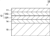
- FIG. 1 is a schematic diagram showing an example of a projection image display member according to an embodiment of the present invention.
- the first polarization conversion layer 14, the selective reflection layer 12, and the second polarization conversion layer 11 are laminated in this order on the support 15.
- the projection image display member 10 may be any structure as long as it has at least the first polarization conversion layer 14, the selective reflection layer 12, and the second polarization conversion layer 11, and the support 15 may be omitted.
- the selective reflection layer is a layer that selectively reflects light as described above.
- the selective reflection layer preferably exhibits selective reflection in a part of the visible light wavelength range.
- the selective reflection layer may reflect light for displaying a projected image.
- the selective reflection layer may have a configuration having a selective reflection layer corresponding to each wavelength range.
- the selective reflection layer 12 shown in FIG. 1 includes a first selective reflection layer 12G that selectively reflects light having a wavelength of 500 to 650 nm and a second selective reflection layer 12G that selectively reflects light having a wavelength of 650 to 900 nm.
- the selective reflection layer 12R and the first selective reflection layer 12G and the second selective reflection layer 12R are stacked in this order on the first polarization conversion layer 14.
- the selective reflection layer is preferably a polarization reflection layer.
- the polarization reflection layer is a layer that reflects linearly polarized light, circularly polarized light, or elliptically polarized light.
- the polarization reflection layer is preferably a circular polarization reflection layer or a linear polarization reflection layer.
- the circularly polarized light reflection layer is a layer that reflects circularly polarized light of either sense and transmits the other at the center wavelength of selective reflection.
- the linearly polarized light reflection layer is a layer that reflects linearly polarized light in one polarization direction and transmits linearly polarized light in a polarization direction orthogonal to the above-described polarization direction at the central wavelength of selective reflection.
- the polarized reflection layer can transmit polarized light that is not reflected, and can also transmit a part of light even in the wavelength range in which the selective reflection layer reflects. Therefore, it is preferable that the tint of the light transmitted through the projection image display member is not easily deteriorated and the visible light transmittance is not easily lowered.
- the selective reflection layer preferably includes a cholesteric liquid crystal layer, and may have a configuration including two or more cholesteric liquid crystal layers.
- the central wavelength of the selective reflection layer is preferably 500 to 650 nm and 650 to 900 nm, more preferably 530 to 630 nm and 670 to 850 nm, and more preferably 550 from the viewpoint of tint and visible light transmittance. More preferably, they are in the range of -610 nm and 680-800 nm.
- the projection image display member When the selective reflection layer includes a cholesteric liquid crystal layer, the projection image display member preferably includes a retardation layer.
- a retardation layer By using the retardation layer in combination with the cholesteric liquid crystal layer, a clear projected image can be displayed.
- the central wavelength of reflection of the cholesteric liquid crystal layer shifts to the short wave side with respect to oblique light.
- the shift of the center wavelength of the reflection to the short wave side is called blue shift.
- a blue shift occurs in the cholesteric liquid crystal layer due to a decrease in the optical path length difference between the layers due to optical interference. Therefore, when observed from an oblique direction, blue shift occurs. Therefore, when the selective reflection layer is composed of a cholesteric liquid crystal layer, it is desirable to shift the central reflection wavelength on the front side of the selective reflection layer to the long wave side by previously correcting the shift of the central wavelength of reflection to the short wave side.
- the center wavelength may be shifted.
- the wavelength range of the selective reflection layer 12 is set in consideration of the blue shift.
- the cholesteric liquid crystal layer means a layer in which a cholesteric liquid crystal phase is fixed.
- the cholesteric liquid crystal layer only needs to be a layer in which the orientation of the liquid crystal compound in the cholesteric liquid crystal phase is maintained.
- the polymerizable liquid crystal compound is placed in the orientation state of the cholesteric liquid crystal phase and then irradiated with ultraviolet rays.
- the layer may be a layer that is polymerized and hardened by heating or the like to form a layer having no fluidity, and at the same time, is changed to a state in which the orientation form is not changed by an external field or an external force.
- the optical properties of the cholesteric liquid crystal phase are retained in the layer, and the liquid crystal compound in the layer may no longer exhibit liquid crystallinity.
- the polymerizable liquid crystal compound may have a high molecular weight due to a curing reaction and may lose the liquid crystallinity.
- the cholesteric liquid crystal phase exhibits circularly polarized light selective reflection that selectively reflects the circularly polarized light of either the right circularly polarized light or the left circularly polarized light and transmits the circularly polarized light of the other sense.
- a film including a layer in which a cholesteric liquid crystal phase exhibiting circularly polarized light selective reflectivity is fixed many films formed from a composition containing a polymerizable liquid crystal compound have been conventionally known. Can refer to technology.
- the selective reflection center wavelength and the half value width of the cholesteric liquid crystal layer can be obtained as follows.
- a peak of transmittance decrease was found in the selective reflection band. Seen.
- the wavelength value on the short wavelength side is ⁇ l (nm) and the wavelength value on the long wavelength side is Is defined as ⁇ h (nm)
- the central wavelength ⁇ of selective reflection and the half width ⁇ can be expressed by the following formulas.
- a head-up display system to be described later, by using light so that the light is obliquely incident on the windshield glass, it is possible to reduce the reflectance on the surface of the glass plate on the projection light incident side. At this time, light also enters the cholesteric liquid crystal layer obliquely.
- light incident in the air with a refractive index of 1 at an angle of 45° to 70° with respect to the normal line of the projected image display portion has an angle of about 26° to 36° for a cholesteric liquid crystal layer having a refractive index of about 1.61.
- the reflected wavelength shifts to the short wavelength side.
- the cholesteric liquid crystal layer having a central wavelength of selective reflection in the range of 650 to 780 nm can reflect projection light in the range of 520 to 695 nm. Since such a wavelength range has a high luminosity factor, the contribution to the brightness of the projected image is high, and as a result, a projected image with high brightness can be realized.
- the pitch of the cholesteric liquid crystal phase depends on the type of chiral agent used with the polymerizable liquid crystal compound or the concentration added, the desired pitch can be obtained by adjusting these.
- the method of measuring the sense and pitch of the spiral use the method described in “Introduction to Liquid Crystal Chemistry”, edited by The Liquid Crystal Society of Japan, Sigma Publishing 2007, page 46, and “Liquid Crystal Handbook”, Liquid Crystal Handbook Editorial Committee Maruzen, page 196 be able to.
- the cholesteric liquid crystal layers are arranged in order from the one having the shorter central wavelength of selective reflection when viewed from the viewing side (inside the vehicle).
- each cholesteric liquid crystal layer a cholesteric liquid crystal layer whose sense of spiral is either right or left is used.
- the sense of the reflected circularly polarized light of the cholesteric liquid crystal layer matches the sense of the spiral.
- the spiral senses of the cholesteric liquid crystal layer having different selective reflection central wavelengths may be the same or different. However, it is preferable that the plurality of cholesteric liquid crystal layers have the same twist direction.
- the projection image display member does not include cholesteric liquid crystal layers having different spiral senses as a cholesteric liquid crystal layer that exhibits selective reflection in the same or overlapping wavelength ranges. This is to prevent the transmittance in a specific wavelength range from decreasing to less than 50%, for example.
- the ⁇ n can be adjusted by adjusting the type or mixing ratio of the polymerizable liquid crystal compound or controlling the temperature at the time of fixing the alignment.
- a plurality of cholesteric liquid crystal layers having the same pitch P and the same spiral sense may be laminated. By stacking cholesteric liquid crystal layers having the same pitch P and the same spiral sense, circularly polarized light selectivity can be increased at a specific wavelength.
- the selective reflection layer 12 preferably has a cholesteric liquid crystal layer having a reflection wavelength band within a wavelength range of 540 to 850 nm and a half width of 150 nm or more.
- the half-value width of the selective reflection layer 12 is 150 nm or more, the cholesteric liquid crystal layer having the central wavelength of the selective reflection becomes the broadband selective reflection layer, and the brightness of the image can be increased.
- a separately prepared cholesteric liquid crystal layer may be laminated with an adhesive or the like, and the polymerizable liquid crystal is directly formed on the surface of the previous cholesteric liquid crystal layer formed by the method described below.
- the liquid crystal composition containing a compound or the like may be applied and the steps of aligning and fixing may be repeated, but the latter is preferred.
- the orientation direction of the liquid crystal molecules on the air interface side of the previously formed cholesteric liquid crystal layer and the cholesteric liquid crystal layer formed thereon This is because the orientations of the liquid crystal molecules on the lower side are the same, and the polarization characteristics of the laminate of the cholesteric liquid crystal layer are good. In addition, interference unevenness that may occur due to uneven thickness of the adhesive layer is not observed.
- the thickness of the cholesteric liquid crystal layer is preferably 0.2 to 10 ⁇ m, more preferably 0.3 to 8.0 ⁇ m, and further preferably 0.4 to 6.0 ⁇ m.
- the total thickness of the cholesteric liquid crystal layer in the projection image display member is preferably 1.0 to 30 ⁇ m, more preferably 1.5 to 25 ⁇ m, and further preferably 2.0 to 20 ⁇ m. preferable.
- the visible light transmittance can be maintained high without reducing the thickness of the cholesteric liquid crystal layer.
- the material used for forming the cholesteric liquid crystal layer include a liquid crystal composition containing a polymerizable liquid crystal compound and a chiral agent (optically active compound). If necessary, the liquid crystal composition described above, which is further mixed with a surfactant or a polymerization initiator and dissolved in a solvent or the like, is applied to a support, an alignment layer, a cholesteric liquid crystal layer as a lower layer, and the like, and after cholesteric alignment aging.
- the cholesteric liquid crystal layer can be formed by fixing the liquid crystal composition by curing.
- the polymerizable liquid crystal compound may be a rod-shaped liquid crystal compound or a discotic liquid crystal compound, but is preferably a rod-shaped liquid crystal compound.
- An example of the rod-shaped polymerizable liquid crystal compound forming the cholesteric liquid crystal layer is a rod-shaped nematic liquid crystal compound.
- rod-shaped nematic liquid crystal compounds examples include azomethines, azoxys, cyanobiphenyls, cyanophenyl esters, benzoic acid esters, cyclohexanecarboxylic acid phenyl esters, cyanophenylcyclohexanes, cyano-substituted phenylpyrimidines, and alkoxy-substituted phenylpyrimidines.
- Phenyldioxane, tolan, and alkenylcyclohexylbenzonitrile are preferably used. Not only a low molecular weight liquid crystal compound but also a high molecular weight liquid crystal compound can be used.
- the polymerizable liquid crystal compound is obtained by introducing a polymerizable group into the liquid crystal compound.
- the polymerizable group include an unsaturated polymerizable group, an epoxy group, and an aziridinyl group, the unsaturated polymerizable group is preferable, and the ethylenically unsaturated polymerizable group is particularly preferable.
- the polymerizable group can be introduced into the molecule of the liquid crystal compound by various methods.
- the number of polymerizable groups contained in the polymerizable liquid crystal compound is preferably 1 to 6, and more preferably 1 to 3 in one molecule. Examples of the polymerizable liquid crystal compound are described in Makromol. Chem.
- the addition amount of the polymerizable liquid crystal compound in the liquid crystal composition is preferably 80 to 99.9 mass% with respect to the solid content mass (mass excluding the solvent) of the liquid crystal composition, and 85 to 99. It is more preferably 0.5% by mass, and particularly preferably 90 to 99% by mass.
- the first selective reflection layer 12G may have a low ⁇ n.
- the low ⁇ n first selective reflection layer 12G can be formed using a low ⁇ n polymerizable liquid crystal compound.
- the low ⁇ n polymerizable liquid crystal compound will be specifically described.
- a narrow band selective reflection layer can be obtained by forming a cholesteric liquid crystal phase by using a low ⁇ n polymerizable liquid crystal compound and fixing it to a film.
- the low ⁇ n polymerizable liquid crystal compound include compounds described in WO2015/115390, WO2015/147243, WO2016/035873, JP-A-2015-163596, and JP-A-2016-53149.
- the description of WO2016/047648 can also be referred to for the liquid crystal composition which provides the selective reflection layer having a narrow half width.
- liquid crystal compound is a polymerizable compound represented by the following formula (I) described in WO2016/047648.
- A represents a phenylene group which may have a substituent or a trans-1,4-cyclohexylene group which may have a substituent
- m is Represents an integer of 3 to 12
- Sp 1 and Sp 2 are each independently a single bond, a straight-chain or branched alkylene group having 1 to 20 carbon atoms, and a straight-chain or branched alkylene group having 1 to 20 carbon atoms.
- One or more —CH 2 — is —O—, —S—, —NH—, —N(CH 3 )—, —C( ⁇ O)—, —OC( ⁇ O)—, or —
- the phenylene group in formula (I) is preferably a 1,4-phenylene group.
- the substituents that may be “may have a substituent” are not particularly limited, and examples thereof include an alkyl group, a cycloalkyl group, an alkoxy group and an alkyl ether.
- the substituent include a group, an amide group, an amino group, a halogen atom, and a substituent selected from the group consisting of a combination of two or more of the above substituents.
- the phenylene group and trans-1,4-cyclohexylene group may have 1 to 4 substituents. When it has two or more substituents, the two or more substituents may be the same or different from each other.
- the alkyl group may be linear or branched.
- the alkyl group preferably has 1 to 30 carbon atoms, more preferably has 1 to 10 carbon atoms, and further preferably has 1 to 6 carbon atoms.
- Examples of the alkyl group include, for example, methyl group, ethyl group, n-propyl group, isopropyl group, n-butyl group, isobutyl group, sec-butyl group, tert-butyl group, n-pentyl group, isopentyl group, neopentyl group.
- Examples thereof include a group, a 1,1-dimethylpropyl group, an n-hexyl group, an isohexyl group, a linear or branched heptyl group, an octyl group, a nonyl group, a decyl group, an undecyl group, and a dodecyl group.
- the above description regarding the alkyl group is the same for the alkoxy group containing an alkyl group.
- specific examples of the alkylene group when referred to as an alkylene group include a divalent group obtained by removing one arbitrary hydrogen atom from each of the above examples of the alkyl group.
- Examples of the halogen atom include a fluorine atom, a chlorine atom, a bromine atom and an iodine atom.
- the cycloalkyl group preferably has 3 to 20 carbon atoms, more preferably has 5 or more carbon atoms, preferably has 10 or less carbon atoms, more preferably has 8 or less carbon atoms, and further preferably has 6 or less carbon atoms.
- Examples of the cycloalkyl group include a cyclopropyl group, a cyclobutyl group, a cyclopentyl group, a cyclohexyl group, a cycloheptyl group, and a cyclooctyl group.
- X 3 represents a single bond, —O—, —S—, or —N(Sp 4 —Q 4 )—, or is a nitrogen atom forming a ring structure together with Q 3 and Sp 3. Show.
- Sp 3 and Sp 4 are each independently one or more of a single bond, a straight-chain or branched alkylene group having 1 to 20 carbon atoms, and a straight-chain or branched alkylene group having 1 to 20 carbon atoms.
- a linking group selected from the group consisting of substituted groups is shown.
- one or more —CH 2 — is —O—, —S—, —NH—, —N(CH 3 )—, —C( ⁇ O)—, —OC( ⁇ O)
- Specific examples of the group substituted with — or —C( ⁇ O)O— include a tetrahydrofuranyl group, a pyrrolidinyl group, an imidazolidinyl group, a pyrazolidinyl group, a piperidyl group, a piperazinyl group, and a morpholinyl group. ..
- the substitution position is not particularly limited. Of these, a tetrahydrofuranyl group is preferable, and a 2-tetrahydrofuranyl group is particularly preferable.
- the m-1 L's may be the same or different from each other.
- Sp 1 and Sp 2 are each independently one or more of a single bond, a straight-chain or branched alkylene group having 1 to 20 carbon atoms, and a straight-chain or branched alkylene group having 1 to 20 carbon atoms.
- a linking group selected from the group consisting of substituted groups is shown.
- Sp 1 and Sp 2 are each independently a carbon atom having a linking group selected from the group consisting of —O—, —OC( ⁇ O)—, and —C( ⁇ O)O— at both ends.
- 1 or a combination of 2 or more is preferably a linking group, and a linear alkylene group having 1 to 10 carbon atoms in which —O— is bonded to both ends is preferable.
- Q 1 and Q 2 each independently represent a hydrogen atom or a polymerizable group selected from the group consisting of the groups represented by the above formulas Q-1 to Q-5, provided that Q 1 and Q 2 are One of them represents a polymerizable group.
- the polymerizable group an acryloyl group (formula Q-1) or a methacryloyl group (formula Q-2) is preferable.
- m represents an integer of 3 to 12, preferably an integer of 3 to 9, more preferably an integer of 3 to 7, and further preferably an integer of 3 to 5.
- the polymerizable compound represented by the formula (I) has, as A, at least one optionally substituted phenylene group and optionally substituted trans-1,4-cyclohexylene group. It is preferable to include at least one.
- the polymerizable compound represented by the formula (I) preferably contains, as A, 1 to 4 trans-1,4-cyclohexylene groups optionally having a substituent, and preferably 1 to 3 trans-1 ,4-cyclohexylene groups which may have a substituent. Is more preferable, and it is still more preferable to include 2 or 3.
- the polymerizable compound represented by the formula (I) preferably contains, as A, at least one phenylene group which may have a substituent, more preferably 1 to 4 and more preferably 1 to 4 It is more preferable to include three, and it is particularly preferable to include two or three.
- the number obtained by dividing the number of trans-1,4-cyclohexylene groups represented by A by m is mc
- polymerizable compound represented by formula (I) examples include the compounds described in paragraphs 0051 to 0058 of WO2016/047648, JP-A Nos. 2013-112631 and 2010-70543, Examples thereof include compounds described in Japanese Patent No. 4725516, WO2015/115390, WO2015/147243, WO2016/035873, JP-A-2015-163596, and JP-A-2016-53149.
- the chiral agent has a function of inducing a helical structure of the cholesteric liquid crystal phase.
- the chiral compound may be selected according to the purpose because the sense of the spiral or the helical pitch induced by the compound differs.
- the chiral agent is not particularly limited, and known compounds can be used.
- Examples of the chiral agent include a liquid crystal device handbook (Chapter 3, Section 4-3, TN, chiral agent for STN, page 199, Japan Society for the Promotion of Science, 142nd Committee, 1989), JP-A-2003-287623, The compounds described in JP-A-2002-302487, JP-A-2002-80478, JP-A-2002-80851, JP-A-2010-181852 or JP-A-2014-034581 are mentioned.
- the chiral agent generally contains an asymmetric carbon atom, but an axially asymmetric compound or a planar asymmetric compound containing no asymmetric carbon atom can also be used as the chiral agent.
- Examples of the axially chiral compound or the planar chiral compound include binaphthyl, helicene, paracyclophane, and derivatives thereof.
- the chiral agent may have a polymerizable group. When both the chiral agent and the liquid crystal compound have a polymerizable group, a repeating unit derived from the polymerizable liquid crystal compound and a chiral agent are generated by a polymerization reaction between the polymerizable chiral agent and the polymerizable liquid crystal compound.
- Polymers having repeating units can be formed.
- the polymerizable group contained in the polymerizable chiral agent is preferably the same group as the polymerizable group contained in the polymerizable liquid crystal compound. Therefore, the polymerizable group of the chiral agent is also preferably an unsaturated polymerizable group, an epoxy group or an aziridinyl group, more preferably an unsaturated polymerizable group, and an ethylenically unsaturated polymerizable group. Particularly preferred. Further, the chiral agent may be a liquid crystal compound.
- an isosorbide derivative As the chiral agent, an isosorbide derivative, an isomannide derivative, or a binaphthyl derivative can be preferably used.
- an isosorbide derivative a commercially available product such as LC756 manufactured by BASF may be used.
- the content of the chiral agent in the liquid crystal composition is preferably 0.01 mol% to 200 mol% of the amount of the polymerizable liquid crystal compound, and more preferably 1 mol% to 30 mol %.
- the liquid crystal composition preferably contains a polymerization initiator.
- the polymerization initiator used is preferably a photopolymerization initiator capable of initiating the polymerization reaction by irradiation with ultraviolet rays.
- the photopolymerization initiator include ⁇ -carbonyl compounds (described in US Pat. No. 2,366,661 and US Pat. No. 2,367,670), acyloin ethers (US Pat. No. 2,448,828), ⁇ -hydrocarbons. Of substituted aromatic acyloin compounds (described in US Pat. No.
- JP-B-63-40799 JP-B-5-29234, JP-A-10-95788, JP-A-10-29997, JP-A-2001-233842, JP-A-2000-80068, JP-A-2006-342166, and JP-A-2006-342166.
- oxadiazole compounds described in US Pat. No. 4,212,970
- an acylphosphine oxide compound or an oxime compound as the polymerization initiator.
- acylphosphine oxide compound for example, IRGACURE 810 (compound name: bis(2,4,6-trimethylbenzoyl)-phenylphosphine oxide) commercially available from BASF Japan Ltd. can be used.
- oxime compound IRGACURE OXE01 (manufactured by BASF), IRGACURE OXE02 (manufactured by BASF), TR-PBG-304 (manufactured by Changzhou Power Electronics Co., Ltd.), ADEKA ARKUL'S NCI-831, ADEKA ARKRUZ NCI-930.
- the polymerization initiator may be used alone or in combination of two or more.
- the content of the photopolymerization initiator in the liquid crystal composition is preferably 0.1% by mass to 20% by mass, and more preferably 0.5% by mass to 5% by mass, with respect to the content of the polymerizable liquid crystal compound. Is more preferable.
- the liquid crystal composition may optionally contain a crosslinking agent in order to improve the film strength after curing and the durability.
- a crosslinking agent one that can be cured by ultraviolet rays, heat, moisture or the like can be preferably used.
- the cross-linking agent is not particularly limited and may be appropriately selected depending on the intended purpose. Examples thereof include polyfunctional acrylate compounds such as trimethylolpropane tri(meth)acrylate and pentaerythritol tri(meth)acrylate; glycidyl (meth).
- Epoxy compounds such as acrylates and ethylene glycol diglycidyl ether; aziridine compounds such as 2,2-bishydroxymethylbutanol-tris[3-(1-aziridinyl)propionate] and 4,4-bis(ethyleneiminocarbonylamino)diphenylmethane; Isocyanate compounds such as hexamethylene diisocyanate and biuret type isocyanate; polyoxazoline compounds having an oxazoline group in the side chain; alkoxysilane compounds such as vinyltrimethoxysilane and N-(2-aminoethyl)3-aminopropyltrimethoxysilane Can be mentioned.
- a known catalyst can be used depending on the reactivity of the cross-linking agent, and the productivity can be improved in addition to the improvement of the film strength and durability. These may be used alone or in combination of two or more.
- the content of the crosslinking agent is preferably 3% by mass to 20% by mass, more preferably 5% by mass to 15% by mass.
- orientation control agent An alignment control agent that contributes to the stable or rapid formation of a cholesteric liquid crystal layer having a planar alignment may be added to the liquid crystal composition.
- the orientation control agent include fluorine (meth)acrylate polymers described in paragraphs [0018] to [0043] of JP2007-272185A, and paragraphs [0031] to [0034] of JP2012-203237A. ] And the like, compounds represented by formulas (I) to (IV), compounds described in JP-A-2013-113913, and the like.
- the orientation control agent one kind may be used alone, or two or more kinds may be used in combination.
- the addition amount of the orientation control agent in the liquid crystal composition is preferably 0.01% by mass to 10% by mass, more preferably 0.01% by mass to 5% by mass, based on the total mass of the polymerizable liquid crystal compound. It is particularly preferably from 0.02% by mass to 1% by mass.
- the liquid crystal composition may contain at least one selected from a surfactant for adjusting the surface tension of the coating film to make the thickness uniform, and various additives such as a polymerizable monomer.
- a polymerization inhibitor, an antioxidant, an ultraviolet absorber, a light stabilizer, a coloring material, and metal oxide fine particles may be added within a range that does not deteriorate the optical performance. Can be added.
- the cholesteric liquid crystal layer is a support, an alignment layer, or a liquid crystal composition prepared by dissolving a polymerizable liquid crystal compound, a polymerization initiator, and a chiral agent, a surfactant, etc., which are added if necessary, in a solvent.
- the laminated film composed of a plurality of cholesteric liquid crystal layers can be formed by repeating the above-described manufacturing process of the cholesteric liquid crystal layer.
- the solvent used for preparing the liquid crystal composition is not particularly limited and may be appropriately selected depending on the intended purpose, but organic solvents are preferably used.
- the organic solvent is not particularly limited and may be appropriately selected depending on the intended purpose. Examples thereof include ketones, alkyl halides, amides, sulfoxides, heterocyclic compounds, hydrocarbons, esters, and ethers. And the like. These may be used alone or in combination of two or more. Among these, ketones are particularly preferable in consideration of environmental load.
- the alignment layer, the coating method of the liquid crystal composition to the cholesteric liquid crystal layer to be the lower layer is not particularly limited and can be appropriately selected depending on the purpose, for example, a wire bar coating method, a curtain coating method, Examples thereof include extrusion coating method, direct gravure coating method, reverse gravure coating method, die coating method, spin coating method, dip coating method, spray coating method, and slide coating method. It can also be carried out by transferring a liquid crystal composition separately coated on a support. By heating the applied liquid crystal composition, the liquid crystal molecules are aligned. The heating temperature is preferably 200°C or lower, more preferably 130°C or lower. By this alignment treatment, an optical thin film in which the polymerizable liquid crystal compound is twisted and aligned so as to have a spiral axis in a direction substantially perpendicular to the film surface is obtained.
- the liquid crystal composition can be cured by further polymerizing the aligned liquid crystal compound.
- the polymerization may be either thermal polymerization or photopolymerization utilizing light irradiation, but photopolymerization is preferred. It is preferable to use ultraviolet rays for the light irradiation.
- the irradiation energy is preferably 20mJ / cm 2 ⁇ 50J / cm 2, 100mJ / cm 2 ⁇ 1,500mJ / cm 2 is more preferable.
- light irradiation may be carried out under heating conditions or under a nitrogen atmosphere.
- the irradiation ultraviolet wavelength is preferably 350 to 430 nm.
- the polymerization reaction rate is preferably high, preferably 70% or more, and more preferably 80% or more.
- the polymerization reaction rate can be determined by measuring the consumption rate of the polymerizable functional group by measuring the infrared absorption spectrum.
- Linear polarized light reflection layer As the selective reflection layer, a linearly polarized light reflection layer may be used as long as it has the same reflectance characteristic as the selective reflection layer described above.
- Examples of the linearly polarized light reflection layer include a polarizer in which thin films having different refractive index anisotropies are laminated. Such a polarizer has a high visible light transmittance similar to that of the cholesteric liquid crystal layer, and is capable of reflecting projection light obliquely incident when used in a head-up display system at a wavelength having high visibility.
- a polarizer in which thin films having different refractive index anisotropies are laminated, for example, those described in Japanese Patent Publication No. 9-506837 can be used.
- a polarizer can be formed using a wide variety of materials when processed under the conditions selected to obtain the refractive index relationship.
- one of the first materials has a different index of refraction than the second material in the chosen direction.
- This difference in index of refraction can be achieved in a variety of ways, including stretching, extrusion, or coating during or after film formation.
- the two materials have similar rheological properties (eg melt viscosity) so that they can be coextruded.
- a commercially available product can be used as the polarizer in which thin films having different refractive index anisotropies are laminated.
- a commercially available product may be used which is a laminate of a reflective polarizing plate and a temporary support.
- Examples of commercially available products include DBEF (registered trademark) (manufactured by 3M Company), and commercially available optical films sold as APF (Advanced Polarizing Film (manufactured by 3M Company)).
- the thickness of the reflective polarizing plate is preferably in the range of 2.0 to 50 ⁇ m, more preferably 8.0 to 30 ⁇ m.
- the difference between the first maximum refractive index and the second refractive index is preferably 0.1 or more, and the number of layers is preferably 4 to 20.
- polarization conversion layer As the polarization conversion layer, a first polarization conversion layer, at least one selective reflection layer, and a second polarization conversion layer are provided in this order.
- the first polarization conversion layer 14, the selective reflection layer 12, and the second polarization conversion layer 11 may be provided in this order from the viewing side as shown in FIG. ..
- the first polarization conversion layer 14 and the second polarization conversion layer 11 satisfy all of the following relational expressions (i) to (v).
- a polarization conversion layer in the projection image display member, it is possible to improve suitability for polarized sunglasses that cuts s-polarized light, which is a main component of glare of reflected light from an oncoming vehicle hood or a puddle. Further, a double image can be suppressed, and in particular, a double image when p-polarized light is incident to form a projected image can be excellently suppressed.
- the polarization conversion layer has a spiral structure of a cholesteric liquid crystal phase, and the visible light having a shorter wavelength than the reflection peak wavelength in the infrared region is used.
- the polarization conversion layer since it exhibits optical rotatory power and birefringence, it is possible to control polarized light in the visible region.
- the s-polarized light incident from the outside of the glass has a large change in polarization due to the film configuration including the retardation layer. Therefore, if the pitch number and the film thickness of the polarization conversion layer are controlled so that the polarization conversion layer can optically compensate, the suitability for polarized sunglasses is improved. it can.
- the first polarization conversion layer and the second polarization conversion layer perform optical compensation so that the s-polarized light incident from the outside of the glass is transmitted through the glass while maintaining the s-polarized light.
- the reason why the performance of cutting s-polarized light that is incident from the oblique direction on the outside of the glass can be improved is that the ⁇ /4 phase difference layer that is generally used for polarization conversion is light that is incident on the slow axis.
- the effect of polarization conversion varies greatly depending on the angle, whereas in the polarization conversion layer with the spiral structure of the cholesteric liquid crystal phase, the direction of the liquid crystal is not uniquely determined, and the angle of incident light changes. It is presumed that the effect of polarization conversion is unlikely to change.
- the reason why the double image can be further suppressed by providing the polarization conversion layer is that light with a wavelength that is not in the selective reflection band of the cholesteric liquid crystal layer undergoes polarization conversion by the cholesteric liquid crystal layer and is reflected on the back surface of the windshield glass. It is presumed that it is possible to suppress the double image based on the above.
- the polarization conversion layer is a layer in which the helical alignment structure of the liquid crystal compound is fixed, and the number of pitches of the spiral structure of the first polarization conversion layer is x 1 , and the film thickness is y 1 (unit: ⁇ m).
- the pitch number of the spiral structure of the second polarization conversion layer is x 2 and the film thickness is y 2 (unit: ⁇ m)
- all the following relational expressions are satisfied.
- First polarization conversion layer (I) 0.3 ⁇ x 1 ⁇ 2.0 (Ii) y 1 ⁇ 1.86 ⁇ 1 +0.13 Second polarization conversion layer: (Iii) 0.25 ⁇ x 2 ⁇ 2.0 (Iv) y 2 ⁇ 1.37 x 2 +5.5 (V) y 2 ⁇ 1.37 x 2 +0.25
- the first polarization conversion layer is provided with a pitch number of 0.3 to 2.0 and a film thickness of 0.5 to 10.0 ⁇ m when the pitch number is 1 when the spiral structure rotates 360 degrees. More preferably, the number is 0.4 to 1.5 and the film thickness is 0.8 to 8.0 ⁇ m, and the pitch number is 0.5 to 1.0 and the film thickness is more preferably 1.0 to 6.0 ⁇ m.
- the second polarization conversion layer is preferably provided with a pitch number of 0.25 to 2.0 and a film thickness of 0.5 to 8.0 ⁇ m. Furthermore, the pitch number is 0.3 to 1.8 and the film thickness is 0. It is more preferably from 0.7 to 7.0 ⁇ m, further preferably from 0.4 to 1.6 in pitch number and 0.9 to 5.0 ⁇ m in film thickness.
- such a polarization conversion layer can be basically formed in the same manner as the above-mentioned cholesteric liquid crystal layer.
- the liquid crystal compound to be used and the chiral to be used so that the pitch number x and the film thickness y of the spiral structure in the polarization conversion layer satisfy the relational expressions (i) to (v). It is necessary to adjust the added amount of the agent and the chiral agent, the film thickness, and the like.
- Each polarization conversion layer and selective reflection layer may be formed independently and then laminated by laminating each layer, or may be directly formed on the lower layer depending on the order of lamination. For example, after forming a first polarization conversion layer on a support, a selective reflection layer made of a cholesteric liquid crystal layer is formed on the first polarization conversion layer, and further a second polarization is formed on the selective reflection layer. A conversion layer may be formed.
- the twist direction of the spiral structure of the first polarization conversion layer and the twist direction of the spiral structure of the second polarization conversion layer may be the same or different.
- the selective reflection layer is a cholesteric liquid crystal layer
- the twist direction of the spiral structure of the first polarization conversion layer and the second polarization conversion layer is the same as the twist direction of the spiral structure of the selective reflection layer. Or they may be different. From the viewpoint of manufacturability, it is preferable that the spiral directions of the first polarization conversion layer, the second polarization conversion layer, and the selective reflection layer have the same twist direction.
- the projected image display member may include a layer other than the selective reflection layer, the first polarization conversion layer, and the second polarization conversion layer. All the other layers are preferably transparent in the visible light region. Further, it is preferable that all the other layers have low birefringence.
- the low birefringence means that the front phase difference is 10 nm or less in the wavelength range where the projection image display member of the windshield glass of the present invention reflects, and the front phase difference is 5 nm or less.
- it is preferable that all the other layers have a small difference in refractive index from the average refractive index (in-plane average refractive index) of the cholesteric liquid crystal layer. Examples of other layers include a support, an alignment layer, and an adhesive layer.
- the support can be used as a substrate when forming the first polarization conversion layer, or can be used as a substrate when forming the cholesteric liquid crystal layer also serving as the first polarization conversion layer.
- the material for the support is not particularly limited.
- the support used for forming the cholesteric liquid crystal layer or the first polarization conversion layer may be a temporary support which is peeled off after the formation of the cholesteric liquid crystal layer, and in a completed projection image display member or windshield glass. Need not be included.
- the support include polyester such as polyethylene terephthalate (PET), polycarbonate, acrylic resin, epoxy resin, polyurethane, polyamide, polyolefin, cellulose derivative, and plastic film such as silicone.
- PET polyethylene terephthalate
- acrylic resin epoxy resin
- polyurethane polyamide
- polyolefin polyamide
- cellulose derivative polyolefin
- plastic film such as silicone.
- glass may be used in addition to the above-mentioned plastic film.
- the thickness of the support may be about 5.0 to 1000 ⁇ m, preferably 10 to 250 ⁇ m, more preferably 15 to 90 ⁇ m.
- the completed projecting image display member or windshield glass includes a support instead of being peeled off as a temporary support
- the support is preferably transparent in the visible light region.
- it when it is used as a substrate when forming the first polarization conversion layer, it preferably has low birefringence.
- the projection image display member may include an alignment layer as a lower layer to which the liquid crystal composition is applied when forming the cholesteric liquid crystal layer or the first polarization conversion layer.
- the alignment layer has a rubbing treatment of organic compounds such as polymers (resins such as polyimide, polyvinyl alcohol, polyester, polyarylate, polyamideimide, polyetherimide, polyamide and modified polyamide), oblique vapor deposition of inorganic compounds, and microgrooves.
- an alignment layer which has an alignment function by applying an electric field, a magnetic field, or light irradiation may be used.
- the alignment layer made of a polymer is subjected to a rubbing treatment and then the liquid crystal composition is applied to the rubbing treated surface.
- the rubbing treatment can be carried out by rubbing the surface of the polymer layer with paper or cloth in a certain direction.
- the liquid crystal composition may be applied to the surface of the support without rubbing the alignment layer or the surface of the support rubbed.
- the alignment layer does not have to be separated from the temporary support to form the projection image display member.
- the thickness of the alignment layer is preferably 0.01 to 5.0 ⁇ m, more preferably 0.05 to 2.0 ⁇ m.
- the adhesive layer is provided, for example, between the cholesteric liquid crystal layers, between the cholesteric liquid crystal layer and the first polarization conversion layer, between the cholesteric liquid crystal layer and the second polarization conversion layer, and between the cholesteric liquid crystal layer and the support. May be. Further, it may be provided between the cholesteric liquid crystal layer and the intermediate film sheet, between the second polarization conversion layer and the intermediate film sheet, or the like.
- the adhesive layer may be formed of an adhesive.
- an adhesive from the viewpoint of curing method, there are hot-melt type, heat-curing type, photo-curing type, reaction-curing type, and pressure-sensitive adhesive type that does not require curing.
- hot-melt type heat-curing type
- photo-curing type photo-curing type
- reaction-curing type reaction-curing type
- pressure-sensitive adhesive type that does not require curing.
- -Based, epoxy acrylate-based, polyolefin-based, modified olefin-based, polypropylene-based, ethylene vinyl alcohol-based, vinyl chloride-based, chloroprene rubber-based, cyanoacrylate-based, polyamide-based, polyimide-based, polystyrene-based, and polyvinyl butyral-based compounds Can be used.
- a photo-curing type is preferable as the curing method, and from the viewpoint of optical transparency and heat resistance, it is preferable to use acrylate-based, urethane acrylate-based, and epoxy acrylate-based materials. preferable.
- the adhesive layer may be formed using a highly transparent adhesive transfer tape (OCA tape).
- OCA tape a highly transparent adhesive transfer tape
- a commercially available product for an image display device particularly a commercially available product for the surface of the image display portion of the image display device may be used.
- Examples of commercially available products include an adhesive sheet manufactured by Panac Co., Ltd. (PD-S1 etc.), an adhesive sheet of MHM series manufactured by Nieei Kako Co., Ltd., and the like.
- the thickness of the adhesive layer is preferably 0.5 to 10 ⁇ m, more preferably 1.0 to 5.0 ⁇ m.
- the thickness of the adhesive layer formed by using the highly transparent adhesive transfer tape may be 10 to 50 ⁇ m, preferably 15 to 30 ⁇ m. It is preferable that the projection image display member is provided with a uniform thickness in order to reduce color unevenness and the like.
- Windshield glass means window glass for vehicles such as cars and trains, airplanes, ships, motorcycles, and vehicles such as play equipment.
- the windshield glass is preferably used as a windshield or a windshield in the traveling direction of the vehicle.
- the visible light transmittance of the windshield glass is preferably 70% or more, more preferably more than 70%, further preferably 75% or more, particularly preferably 80% or more. It is preferable that the visible light transmittance described above is satisfied at any position of the windshield glass, and in particular, a portion displaying a projected image (hereinafter, referred to as a projected image display portion) satisfies the above visible light transmittance. Is preferred.
- the projection image display member has a high visible light transmittance in the wavelength range of high visibility, so that the visible light transmission described above can be used when any of the glasses generally used for windshield glass is used. It can be configured to satisfy the rate.
- the windshield glass is not particularly limited, and is appropriately determined according to the object on which the windshield glass is placed.
- it may be a flat surface or a three-dimensional shape having a curved surface such as a concave surface or a convex surface.
- the windshield glass formed for a vehicle to which the vehicle is applied it is possible to specify the face that faces upward, the observer side, the driver side, and the inside such as the inside of the vehicle during normal use.
- the windshield glass may have a uniform thickness or a non-uniform thickness in the projected image display portion.
- it may have a wedge-shaped cross-sectional shape like the glass for vehicles described in Japanese Patent Publication No. 2011-505330, and the thickness of the projected image display portion may be non-uniform, but the thickness of the projected image display portion is not uniform. It is preferably uniform.
- the projection image display member may be provided on the projection image display portion of the windshield glass.
- the projected image display portion can be formed by providing the projected image display member on the outer surface of the glass plate of the windshield glass, or by providing it on the intermediate layer of the windshield glass having the structure of laminated glass as described later.
- the above-mentioned projection image display member may be provided on the viewing side or on the opposite side as viewed from the glass plate. Is preferably provided in the. Since the scratch resistance is lower than that of the glass plate, the projection image display member is more preferably provided in the intermediate layer in order to protect the projection image display member.
- the projected image display part is a part that can display a projected image by reflected light, and may be a part that can visually display a projected image projected from a projector or the like.
- the projection image display portion functions as a combiner for the head-up display system.
- the combiner can visually display the image projected from the projector, and when the combiner is viewed from the same side where the image is displayed, the information on the opposite side is displayed. Or, it means an optical member capable of simultaneously observing a landscape. That is, the combiner has a function as an optical path combiner for displaying the external light and the image light in a superimposed manner.
- the projected image display portion may be on the entire surface of the windshield glass, or may be a part of the entire area of the windshield glass, but is preferably a part.
- the projection image display part may be provided at any position of the windshield glass, but when used as a head-up display system, it should be located at a position where it can be easily seen by an observer such as a driver. It is preferably provided so that a virtual image is shown.
- the position where the projection image display portion is provided may be determined based on the relationship between the position of the driver's seat of the vehicle and the position where the projector is installed.
- the projected image display portion may be flat without a curved surface, but may have a curved surface and has a concave or convex shape as a whole to enlarge or reduce the projected image. It may be displayed.
- the windshield glass may have a laminated glass structure.
- the windshield glass may have a configuration in which the projection image display member is arranged between the first glass plate and the second glass plate, and the windshield glass may be arranged between the first glass plate and the projection image display member and the projection image display member.
- An intermediate film is preferably provided on at least one of the image display member and the second glass plate.
- the first glass plate is located farther from the viewing side, and the second glass plate is located closer to the viewing side.
- glass plates generally used for windshield glass can be used.
- a glass plate having a visible light transmittance of 80% or less such as 73% or 76% may be used, such as green glass having a high heat shielding property.
- the windshield glass having a visible light transmittance of 70% or more even in the projection image display portion. can be produced.
- the thickness of the glass plate is not particularly limited, but may be about 0.5 to 5.0 mm, preferably 1.0 to 3.0 mm, more preferably 2.0 to 2.3 mm.
- the materials or thicknesses of the first glass plate and the second glass plate may be the same or different.
- the windshield glass having the structure of laminated glass can be manufactured using a known laminated glass manufacturing method. Generally, after sandwiching an interlayer film for laminated glass between two glass plates, heat treatment and pressure treatment (treatment using a rubber roller, etc.) are repeated several times, and finally an autoclave or the like is used. Then, it can be manufactured by a method of performing heat treatment under pressure.
- the windshield glass having the structure of the laminated glass including the projection image display member in the intermediate film is formed even after the ordinary laminated glass manufacturing process after forming the projection image display member on the surface of the glass plate.
- the laminated interlayer film sheet for laminated glass including the above-mentioned projection image display member may be used as an interlayer film sheet to be formed by the above-mentioned heat treatment and pressure treatment.
- the glass plate forming the projection image display member may be the first glass plate or the second glass plate. At this time, the projection image display member is attached to a glass plate with an adhesive, for example.
- Interlayer film sheet Any known interlayer film sheet may be used as the interlayer film sheet when the interlayer film sheet that does not include the projection image display member is used.
- a resin film containing a resin selected from the group consisting of polyvinyl butyral (PVB), ethylene-vinyl acetate copolymer, and chlorine-containing resin can be used.
- the above-mentioned resin is preferably the main component of the interlayer film sheet.
- the term “main component” means a component that accounts for 50% by mass or more of the interlayer film sheet.
- polyvinyl butyral or ethylene-vinyl acetate copolymer is preferable, and polyvinyl butyral is more preferable.
- the resin is preferably a synthetic resin.
- Polyvinyl butyral can be obtained by acetalizing polyvinyl alcohol with butyraldehyde.
- the preferred lower limit of the degree of acetalization of polyvinyl butyral is 40%, the preferred upper limit is 85%, the more preferred lower limit is 60%, and the more preferred upper limit is 75%.
- Polyvinyl alcohol is usually obtained by saponifying polyvinyl acetate, and polyvinyl alcohol having a saponification degree of 80 to 99.8 mol% is generally used.
- the preferred lower limit of the degree of polymerization of polyvinyl alcohol is 200, and the preferred upper limit is 3000. If the polymerization degree of polyvinyl alcohol is 200 or more, the penetration resistance of the obtained laminated glass is less likely to decrease, and if it is 3000 or less, the moldability of the resin film is good, and the rigidity of the resin film does not become too large. Good workability.
- a more preferable lower limit is 500 and a more preferable upper limit is 2000.
- the laminated interlayer film sheet for laminated glass including the projection image display member can be formed by laminating the projection image display member on the surface of the above-mentioned interlayer film sheet.
- the projection image display member may be formed by sandwiching it between the above-mentioned two interlayer film sheets.
- the two interlayer film sheets may be the same or different, but are preferably the same.
- a known bonding method can be used for bonding the projected image display member and the interlayer film, but it is preferable to use a lamination treatment. In order to prevent the laminate and the interlayer film sheet from peeling after processing, it is preferable to carry out the laminating treatment under a condition of heating and pressurizing to some extent.
- the temperature of the film surface on the side where the interlayer film is adhered is preferably 50 to 130°C, more preferably 70 to 100°C.
- the pressurizing condition is preferably less than 2.0 kg/cm 2 (less than 196 kPa), more preferably 0.5 to 1.8 kg/cm 2 (49 to 176 kPa), and more preferably 0.5 to The range of 1.5 kg/cm 2 (49 to 147 kPa) is more preferable.
- the support may be peeled off at the same time as, immediately after, or immediately before the lamination. That is, the laminated interlayer film sheet obtained after lamination may not have a support.
- An example of a method for producing a laminated interlayer film sheet for laminated glass is (1) A first step of bonding a projection image display member on the surface of a first interlayer film sheet to obtain a first laminate, and (2) Second step of bonding the second interlayer film sheet to the surface of the projection image display member in the first laminate opposite to the surface to which the first interlayer film sheet is bonded ,including.
- the first step the projection image display member and the first interlayer film sheet were bonded together, the support was peeled off, and in the second step, the second interlayer film sheet was peeled off the support body.
- a laminated interlayer film sheet for laminated glass which does not include a support, can be manufactured by the method for manufacturing a laminated interlayer film sheet for laminated glass, which is attached to a surface, and by using this laminated interlayer film sheet for laminated glass, A laminated glass that does not include a support can be easily produced.
- the temperature of the substrate when peeling the support from the projection image display member is preferably 40° C. or higher, and is preferably 40 to 60° C. More preferable.
- the light that passes through the selective reflection layer is either circularly polarized light with the opposite sense to the circularly polarized light that is reflected by the selective reflection layer described above, or is polarized light in the orthogonal direction, and is reflected from the back side surface.
- the layer on the back side of the selective reflection layer has a low birefringence
- the light is not likely to cause a remarkable double image because most of the polarized light is reflected by the selective reflection layer. ..
- most of the projected light can be reflected by the selective reflection layer.
- the reflected light from the front surface can cause a noticeable double image.
- the distance from the center of gravity of the selective reflection layer to the surface in front of the windshield glass seen from the light incident side is a certain value or more, a double image may become remarkable.
- the total thickness of layers on the first polarization conversion layer side of the selective reflection layer (excluding the thickness of the selective reflection layer), that is, the selective reflection layer
- the layer on the visual recognition side of the selective reflection layer include a support, an intermediate film sheet, and a second glass plate, in addition to the first polarization conversion layer.
- the windshield glass of the present invention in the projection image display using p-polarized light as described later, a remarkable double image occurs even when the total thickness of layers on the viewing side of the selective reflection layer is as described above.
- the projected image can be visually recognized without any need.
- Windshield glass can be used as a component of a head-up display system.
- the head-up display system preferably includes a projector.
- the “projector” is a “device that projects light or an image”, and includes a “device that projects a drawn image”, and emits p-polarized projection light carrying an image to be displayed.
- the projector is arranged so that the projected image of p-polarized light carrying the image to be displayed can be incident on the projection image display member in the windshield glass at an oblique incident angle. Good.
- the projector includes a drawing device and reflectively displays an image (real image) drawn on a small intermediate image screen as a virtual image by a combiner.
- the projector emits p-polarized light and has a variable virtual image forming distance, that is, a virtual image forming position.
- a projector used in a known head-up display system can be used as long as it can emit p-polarized emitted light and can change the image formation distance of a virtual image.
- a method of changing the image formation distance of the virtual image in the projector for example, a method of moving an image generation surface (screen) (see Japanese Patent Application Laid-Open No. 2017-212302), a method of switching and using a plurality of optical paths having different optical path lengths, are used.
- a method of changing optical path length by inserting and/or moving mirror for example, a method of changing optical path length by inserting and/or moving mirror, method of changing focal length by using combined lens as imaging lens, method of moving projector 22, imaging of virtual image Examples thereof include a method of switching and using a plurality of projectors having different distances, a method of using a variable focus lens (see WO2010/116912), and the like.
- the projector may be one that can continuously change the image forming distance of the virtual image or one that can switch the image forming distance of the virtual image at two or more than two points.
- At least two virtual images among the virtual images of the light projected by the projector have different imaging distances of 1 m or more. Therefore, when the projector is capable of continuously changing the image forming distance of the virtual image, it is preferable that the image forming distance of the virtual image can be changed by 1 m or more.
- the use of such a projector is preferable in that it can appropriately cope with a case where the distance of the line of sight of the driver is greatly different, such as traveling at a normal speed on an ordinary road and traveling at a high speed on an expressway.
- the drawing device may be a device which itself displays an image or a device which emits light capable of drawing an image.
- the light from the light source may be adjusted by a drawing method such as a light modulator, a laser brightness modulating means, or a light deflecting means for drawing.
- the drawing device means a device including a light source, and further including a light modulator, a laser brightness modulating unit, a light deflecting unit for drawing, or the like according to a drawing method.
- the light source is not particularly limited, and an LED (light emitting diode), an organic light emitting diode (OLED), a discharge tube, a laser light source, or the like can be used.
- the LED and the discharge tube are preferable because they are suitable as the light source of the drawing device that emits linearly polarized light, and the LED is particularly preferable. This is because the LED has an emission wavelength that is not continuous in the visible light region, and is therefore suitable for combination with a combiner that uses a cholesteric liquid crystal layer that exhibits selective reflection in a specific wavelength region as described later.
- the drawing method can be selected according to the light source used or the application and is not particularly limited.
- Examples of the drawing method include a fluorescent display tube, an LCD (Liquid Crystal Display) method using a liquid crystal, an LCOS (Liquid Crystal on Silicon) method, a DLP (registered trademark) (Digital Light Processing) method, and a scanning method using a laser.
- Etc. The drawing method may be a method using a fluorescent display tube integrated with a light source.
- the LCD method is preferable as the drawing method.
- the DLP method is a display system using a DMD (Digital Micromirror Device), in which micromirrors corresponding to the number of pixels are arranged for drawing and light is emitted from a projection lens.
- DMD Digital Micromirror Device
- the scanning method is a method in which a light beam is scanned on a screen and an image is imaged by utilizing an afterimage of the eye.
- a scanning method using a laser brightness-modulated laser light of each color of red light, green light, and blue light is bundled into one light beam by a combining optical system or a condenser lens, and the light beam is converted into a light beam. It suffices that the image is scanned by the deflecting means and drawn on the intermediate image screen described later.
- the brightness modulation of the laser light of each color of red light, green light, and blue light may be directly performed as the intensity change of the light source, or may be performed by an external modulator.
- the light deflecting means include a galvano mirror, a combination of a galvano mirror and a polygon mirror, or MEMS (Micro Electro Mechanical Systems), and among these, MEMS is preferable.
- the scanning method include a random scan method and a raster scan method, but it is preferable to use the raster scan method. In the raster scan method, laser light can be driven, for example, at a resonance frequency in the horizontal direction and a sawtooth wave in the vertical direction. Since the scanning method does not require a projection lens, it is easy to downsize the device.
- the light emitted from the drawing device may be linearly polarized light or natural light (non-polarized light).
- the light emitted from the drawing device included in the head-up display system is preferably linearly polarized light.
- the drawing method is the LCD method or the LCOS method and a drawing device using a laser light source
- the emitted light is essentially linearly polarized light.
- the polarization directions (transmission axis directions) of the polarized light of the plurality of lights are the same or orthogonal to each other.
- the polarization directions (transmission axis directions) of the polarized light of the plurality of lights are the same or orthogonal to each other.
- the polarization directions (transmission axis directions) of the polarized light of the plurality of lights are the same or orthogonal to each other.
- the polarization directions (transmission axis directions) of the polarized light of the plurality of lights are the same or orthogonal to each other.
- the drawing device may use an intermediate image screen.
- the "intermediate image screen” is a screen on which an image is drawn. That is, when the light emitted from the drawing device is not yet visible as an image, the light causes the drawing device to form a visible image on the intermediate image screen.
- the image drawn on the intermediate image screen may be projected on the combiner by light passing through the intermediate image screen, or may be reflected on the intermediate image screen and projected on the combiner.
- intermediate image screens include scattering films, microlens arrays, and rear projection screens.
- a plastic material is used as the intermediate image screen, if the intermediate image screen has birefringence, the polarization plane or the light intensity of the polarized light incident on the intermediate image screen is disturbed, and color unevenness is likely to occur in the combiner.
- the problem of color unevenness can be reduced by using a retardation film having a predetermined retardation.
- the intermediate image screen one having a function of spreading and transmitting incident light rays is preferable. This is because the projected image can be enlarged and displayed.
- An example of such an intermediate image screen is a screen including a microlens array.
- the microarray lens used in the head-up display is described in, for example, Japanese Patent Application Laid-Open No. 2012-226303, Japanese Patent Application Laid-Open No. 2010-145745, and Japanese Patent Laid-Open No. 2007-523369.
- the projector may include a reflecting mirror or the like that adjusts the optical path of the projection light formed by the drawing device.
- JP-A-2-141720, JP-A-10-96874, JP-A-2003-98470, and US Pat. No. 5,013,134 are disclosed.
- JP-A-2-141720, JP-A-10-96874, JP-A-2003-98470, and US Pat. No. 5,013,134 are disclosed.
- Japanese Patent Publication No. 2006-512622 refers to Japanese Patent Publication No. 2006-512622.
- the windshield glass is particularly useful for a head-up display system that uses a laser, an LED, an OLED (organic light emitting diode) or the like as a light source in combination with a projector whose emission wavelength is not continuous in the visible light region. This is because the central wavelength of selective reflection of the cholesteric liquid crystal layer can be adjusted according to each emission wavelength. It can also be used for projection of a display such as an LCD (Liquid Crystal Display) whose display light is polarized.
- LCD Liquid Crystal Display
- the incident light is preferably incident at an oblique incident angle of 45° to 70° with respect to the normal line of the projection image display member.
- the Brewster angle at the interface between the glass having a refractive index of about 1.51 and the air having a refractive index of 1 is about 56°, and the p-polarized light is made incident within the above-mentioned angle range so that the incident light for displaying the projected image is displayed.
- the reflected light from the surface of the windshield glass on the viewing side with respect to the selective reflection layer is less, and image display with less influence of double image is possible.
- the above-mentioned angle is between 50° and 65°.
- the projected image may be observed on the incident side of the projected light at an angle of 45° to 70°, preferably 50° to 65° on the side opposite to the incident light with respect to the normal line of the selective reflection layer. Any configuration is possible.
- ⁇ Incident light may be incident from any direction such as up, down, left and right of the windshield glass, and may be determined according to the viewing direction. For example, a configuration in which the light is incident at an oblique incident angle as described above from the downward direction during use is preferable.
- the projection light at the time of displaying the projected image on the head-up display is p-polarized light that vibrates in the direction parallel to the incident surface.
- the light emitted from the projector is not linearly polarized light, it may be p-polarized by arranging and using a linear polarizing film on the side of the light emitted from the projector, and it is p-polarized in the optical path from the projector to the windshield glass. Good.
- the polarization direction is adjusted wavelength-selectively and p-polarized light is used in all wavelength ranges. It is preferable to make it incident.
- the head-up display system may be a projection system in which the virtual image forming position is variable.
- a projection system is described in, for example, Japanese Patent Laid-Open No. 2009-150947.
- the virtual image forming position is a position where the driver of the vehicle can visually recognize the virtual image, and is, for example, a position 1000 mm or more away from the tip of the windshield glass when seen from the normal driver.
- the glass is nonuniform (wedge shape) in the projection image display portion as described in Japanese Patent Laid-Open No. 2011-505330
- the virtual image forming position is changed, the angle of the wedge shape is also changed. Need to do.
- FIG. 3 is a schematic view showing an example of a head-up display having the projection image display member of the embodiment of the present invention
- FIG. 4 is an example of a windshield glass having the projection image display member of the embodiment of the present invention. It is a schematic diagram which shows.
- the head-up display system 20 has a projector 22 and a windshield glass 24, and is used in vehicles such as passenger cars, for example.
- each component of the head-up display system 20 is as already described.
- the head-up display system 20 will also be referred to as a HUD 20.
- the windshield glass 24 has a first glass plate 28, a second glass plate 30, a projection image display member 10, an intermediate film 36, and an adhesive, as conceptually shown in FIG. And layer 38.
- the projected image display member 10 has a second polarization conversion layer 11, a selective reflection layer 12, and a first polarization conversion layer 14.
- the vertical direction Y of the windshield glass 24 is aligned with the axis H of the first polarization conversion layer 14 shown in FIG.
- the up-down direction Y of the windshield glass 24 is a direction defined by the ground side of the vehicle or the like in which the windshield glass 24 is arranged as the lower side and the opposite side of the lower side as the upper side.
- the windshield glass 24 may be placed so as to be inclined because of its structure or design. In this case, the vertical direction Y is on the surface 25 of the windshield glass 24. It will be in the direction along.
- the projector 22 is as described above.
- the projector 22 is a known projector used for a HUD as long as it can emit p-polarized projection light carrying an image to be displayed and has a variable virtual image forming distance, that is, a virtual image forming position. Is available.
- the projector 22 irradiates the windshield glass 24 (second glass plate 30) with p-polarized projection light.
- the projection light that the projector 22 irradiates the windshield glass 24 is s-polarized light
- a large amount of reflection of the projection light by the second glass plate 30 and the first glass plate 28 of the windshield glass 24 causes a double image to be observed.
- the projector 22 irradiates the windshield with p-polarized projection light at a Brewster's angle. As a result, it is possible to eliminate the reflection of the projection light on the second glass plate 30 and the first glass plate 28 and display a clearer image.
- the windshield glass 24 is a so-called laminated glass, and includes an intermediate film 36, a projection image display member 10, and an adhesive layer 38 between a first glass plate 28 and a second glass plate 30. Have.
- the projection image display member 10 is configured by laminating the second polarization conversion layer 11, the selective reflection layer 12, and the first polarization conversion layer 14, and the first polarization conversion layer 14 is the second polarization conversion layer 14.
- the glass plate 30 side that is, the incident side of projected light.
- the projection light is incident on the surface 30a of the second glass plate 30.
- the selective reflection layer 12 is the main body of the projection image display member 10, and reflects a part of the incident light and transmits a part thereof, as in a normal half mirror.
- the projection image display member 10 is adhered to the first glass plate 28 by the intermediate film 36, and is adhered to the second glass plate 30 by the adhesive layer 38 so that the first glass plate 28 and the second glass plate 28 are adhered to each other. It is sandwiched between the glass plate 30.
- the first glass plate 28 and the second glass plate 30 of the windshield glass 24 are basically provided in parallel. That is, the cross section of the windshield glass 24 is not wedge-shaped.
- Both the first glass plate 28 and the second glass plate 30 are known glasses (glass plates) used for windshields of vehicles and the like. Therefore, the forming material, the thickness, the shape, and the like may be the same as those of the glass used for the known windshield.
- the first glass plate 28 and the second glass plate 30 shown in FIG. 4 are both flat plates, but the present invention is not limited to this, and a part may be a curved surface or the entire surface may be a curved surface.
- the intermediate film 36 prevents the glass from penetrating into the vehicle and scattering when an accident occurs, and further adheres the projection image display member 10 and the first glass plate 28.
- known intermediate layers and adhesive layers used for windshields of laminated glass can be used.
- materials for forming the intermediate film 36 include polyvinyl butyral (PVB), ethylene-vinyl acetate copolymer, chlorine-containing resin, and polyurethane.
- the thickness of the intermediate film 36 is also not limited, and the thickness according to the forming material and the like may be set similarly to the known intermediate film of windshield glass.
- the adhesive layer 38 is a layer made of a coating type adhesive.
- the projected image display member 10 is attached to the second glass plate 30 by the adhesive layer 38.
- the adhesive layer 38 There is no limitation on the adhesive layer 38, as long as it can ensure the transparency required for the windshield glass 24 and can bond the projection image display member 10 and the glass with a necessary bonding force. It is possible to use those made of various known coating type adhesives.
- the same adhesive layer 38 as the intermediate film 36 may be used, or as an example, polyvinyl butyral (PVB) may be used. Other than this, an acrylate adhesive or the like can be used for the adhesive layer 38.
- the adhesive layer 38 may be the same as the above-mentioned adhesive layer, as described below.
- the adhesive layer 38 may be formed of an adhesive similarly to the above-mentioned adhesive layer. From the viewpoint of curing method, there are hot-melt type, heat-curing type, photo-curing type, reaction-curing type, and pressure-sensitive adhesive type that does not require curing.
- hot-melt type heat-curing type
- photo-curing type photo-curing type
- reaction-curing type reaction-curing type
- pressure-sensitive adhesive type that does not require curing.
- -Based, epoxy acrylate-based, polyolefin-based, modified olefin-based, polypropylene-based, ethylene vinyl alcohol-based, vinyl chloride-based, chloroprene rubber-based, cyanoacrylate-based, polyamide-based, polyimide-based, polystyrene-based, and polyvinyl butyral-based compounds Can be used.
- a photo-curing type is preferable as the curing method, and from the viewpoint of optical transparency and heat resistance, it is preferable to use acrylate-based, urethane acrylate-based, and epoxy acrylate-based materials. preferable.
- the adhesive layer 38 may be formed using a highly transparent adhesive transfer tape (OCA tape).
- OCA tape a commercially available product for an image display device, particularly a commercially available product for the surface of the image display portion of the image display device may be used.
- Examples of commercially available products include an adhesive sheet manufactured by Panac Co., Ltd. (PD-S1 etc.), an adhesive sheet of MHM series manufactured by Nieei Kako Co., Ltd.
- the thickness of the adhesive layer 38 there is no limitation on the thickness of the adhesive layer 38. Therefore, the thickness at which a sufficient adhesive force can be obtained may be appropriately set according to the forming material of the adhesive layer 38. Here, if the adhesive layer 38 is too thick, it may not be possible to attach the projection image display member 10 to the first glass plate 28 or the second glass plate 30 while sufficiently maintaining the flatness described later. Considering this point, the thickness of the adhesive layer 38 is preferably 0.1 to 800 ⁇ m, more preferably 0.5 to 400 ⁇ m.
- an adhesive layer 38 is provided between the projection image display member 10 and the second glass plate 30, and the projection image display member 10 and the first glass plate 28 are provided with an intermediate film 36. It is pasted on, but it is not limited to this. That is, an adhesive layer may be provided between the projected image display member 10 and the first glass plate 28, and an intermediate film may be provided between the projected image display member 10 and the second glass plate 30.
- the windshield glass 24 does not have the intermediate film 36, and the projection image display member 10 and the first glass plate 28 are attached to each other, and the projection image display member 10 and the second glass plate 30 are attached.
- the adhesive layer 38 may be used for the attachment.
- the projection image display member 10 is formed by laminating a selective reflection layer 12, a first polarization conversion layer 14, and a second polarization conversion layer 11.
- the projection image display member 10 having the first polarization conversion layer 14 is provided with the first polarization conversion layer 14 facing the second glass plate 30 side, that is, the projection light incident side. Therefore, the second polarization conversion layer 11 is directed to the first glass plate 28 side, that is, the side opposite to the incident side of the projected light.
- the windshield glass 24 has the projection image displaying member 10 between the first glass plate 28 and the second glass plate 30, and the projection layer image displaying member 10 (the first projection image displaying member 10 (first part) is provided by the adhesive layer 38.
- the polarization conversion layer 14 is attached to the second glass plate 30, and the intermediate film 36 is used to attach the projection image display member 10 (first polarization conversion layer 11) to the first glass plate 28.
- an image observer that is, a driver D observes a virtual image of a projected image by the projector 22, which is projected by the projector 22 and reflected by the windshield glass 24.
- the projected image of the projector is reflected by the windshield glass, and the reflected light is observed.
- a general windshield is a laminated glass, and has two pieces of glass, an inner surface side and an outer surface side. Therefore, in the HUD, there is a problem that a double image is observed by the driver due to the reflected light from the two glasses.
- the cross-sectional shape of the windshield is made wedge-shaped so that the reflection of the inner surface side glass and the reflection of the outer surface side glass are overlapped, and a double image cannot be seen. I am trying.
- the wedge-type windshield for example, in order to respond to the difference in the line of sight of the driver between normal running with a close line of sight and high-speed running with a long line of sight, if the imaging distance of the virtual image is changed, , The angle of the wedges on the windshield is incorrect, and the image observed by the driver becomes a double image.
- the windshield glass 24 has the projection image display member 10 between the first glass plate 28 and the second glass plate 30, and the driver D displays the projection image.
- the reflection of the projection light of the projector 22 is basically dominated by the reflection of the projection image display member 10, so that a double image is basically generated. Does not happen. Therefore, in the HUD 20 that uses the projection image display member 10 for the windshield glass 24, it is not necessary to make the cross section of the windshield glass 24 (intermediate film 36) into a wedge shape, and therefore, the virtual image forming distance can be changed. However, a double image does not occur.
- the intermediate film 36 is provided only between the projection image display member 10 and the first glass plate 28, and the second glass plate 30 side of the projection image display member 10 is By directly adhering it to the first glass plate 28 with the adhesive layer 38 made of a coating type adhesive, the flatness of the projection image display member 10 is secured, and the image clarity is set to 0.
- the optical comb having a width of 5 mm is 90% or more, and the optical comb having a width of 0.125 mm is 70% or more.
- the surface of the first glass plate 28 to which the projection image display member 10 is attached is polished by the intermediate film 36 to improve the flatness of the surface of the first glass plate 28. Good.
- the glass may be polished by a known method using a polishing material (cerium oxide powder or the like) and a polishing apparatus having a polishing pad.
- the projection image display member 10 Has insufficient flatness and the image is distorted when the image forming distance of the virtual image is changed.
- the image clarity of the windshield glass 24 is preferably 95% or more with an optical comb having a width of 0.5 mm, 80% or more with an optical comb having a width of 0.125 mm, and 98% or more with an optical comb having a width of 0.5 mm and a width of 0.
- An optical comb of 0.125 mm is more preferably 84% or more.
- the present invention is basically configured as described above. Although the projection image display member, the windshield glass, and the head-up display system of the present invention have been described above in detail, the present invention is not limited to the above-described embodiments, and various modifications are possible without departing from the gist of the present invention. Of course, improvements and changes may be made.
- Comparative Example 1 was manufactured in the same manner as in the other Examples and Comparative Examples except that the retardation layer described below was used instead of the first polarization conversion layer, and that the second polarization conversion layer was not provided.
- Comparative Example 2 is manufactured in the same manner as other Examples and Comparative Examples except that a retardation layer described later is used instead of the first polarization conversion layer.
- Example 4 is manufactured in the same manner as other examples and comparative examples except that the reflective layer is a linearly polarized light reflective layer described later.
- the reflective layer is a linearly polarized light reflective layer, which will be described later, and is manufactured in the same manner as in the other Examples and Comparative Example except that there is no polarization conversion layer.
- Coating liquids 1 and 2 for forming cholesteric liquid crystal layer Coating liquids 1 and 2 for forming cholesteric liquid crystal layer
- coating liquid 2 that forms a cholesteric liquid crystal layer that forms a cholesteric liquid crystal layer that reflects light in the wavelength range of 700 nm The following components were mixed to prepare a coating liquid for forming a cholesteric liquid crystal layer having the following composition.
- Coating liquid for forming cholesteric liquid crystal layer/mixture 1 100 parts by mass Fluorine-based horizontal alignment agent 1 (alignment control agent 1 below) 0.05 parts by mass Fluorine-based horizontal alignment agent 2 (alignment control agent 2 below) 0.02 parts by weight Part/right-turning chiral agent LC756 (manufactured by BASF) Adjustment/polymerization initiator IRGACURE OXE01 (manufactured by BASF) according to the target reflection wavelength 1.0 parts by mass solvent (methyl ethyl ketone) Amount solute concentration is 20% by mass
- the cholesteric liquid crystal layer forming coating liquid 1 and the cholesteric liquid crystal layer forming coating liquid 2 were prepared by adjusting the prescription amount of the right-handed chiral agent LC756 having the above-mentioned coating liquid composition.
- a coating liquid 1 for forming a cholesteric liquid crystal layer or a coating liquid 2 for forming a cholesteric liquid crystal layer a single-layer cholesteric liquid crystal layer having a film thickness of 3 ⁇ m was formed on a temporary support in the same manner as in the half mirror formation described below.
- the produced cholesteric liquid crystal layers were all right circularly polarized light reflection layers, and the central reflection wavelengths were coating liquid 1 having a wavelength of 580 nm and coating liquid 2 having a wavelength of 700 nm.
- Coating liquid for forming retardation layer (Coating liquid for forming retardation layer) The following components were mixed to prepare a coating liquid for forming a retardation layer having the following composition.
- Coating liquid for forming retardation layer/mixture 1 100 parts by mass Fluorine-based horizontal alignment agent 1 (alignment control agent 1) 0.05 parts by mass Fluorine-based horizontal alignment agent 2 (alignment control agent 2) 0.01 parts by mass Polymerization initiator IRGACURE OXE01 (manufactured by BASF) 1.0 parts by mass solvent (methyl ethyl ketone) Amount solute concentration is 20% by mass
- Coating liquid for forming polarization conversion layer (Coating liquid for forming polarization conversion layer) The following components were mixed to prepare a coating liquid for forming a polarization conversion layer having the following composition.
- Polarization conversion layer forming coating liquid/mixture 1 100 parts by mass Fluorine-based horizontal alignment agent 1 (following alignment control agent 1) 0.05 parts by mass Fluorine-based horizontal alignment agent 2 (alignment control agent 2 below) 0.02 parts by mass Part/right-turning chiral agent LC756 (manufactured by BASF) Adjustment/polymerization initiator IRGACURE OXE01 (manufactured by BASF) adjusted according to the target pitch number and the reflection wavelength that matches the film thickness 1.0 parts by mass solvent (methyl ethyl ketone) Amount solute concentration is 20% by mass
- the coating liquid for forming the polarization conversion layer was prepared so that the desired center wavelength of reflection ⁇ was obtained by adjusting the prescription amount of the right-handed chiral agent LC756 having the above-mentioned coating liquid composition. Since the film thickness d of the spiral structure can be expressed by the relational expression of pitch (reflection center wavelength ⁇ /in-plane average refractive index n) ⁇ pitch number, the film thickness and the pitch number were specified and ⁇ was determined.
- the pitch number is a twist angle (pitch number ⁇ 360°) obtained by forming a single-layer cholesteric liquid crystal layer having a desired film thickness on a temporary support and fitting the measured values of AxoScan (manufactured by Axometrics). I asked from. Table 1 shows combinations of the number of pitches, the film thickness, and ⁇ of the polarization conversion layers, which are the targets of the adjusted coating liquid for forming the polarization conversion layer.
- ⁇ Saponification of cellulose acylate film> A 40 ⁇ m cellulose acylate film obtained by the same production method as in Example 20 of WO 2014/112575 was passed through a dielectric heating roll at a temperature of 60° C., and the film surface temperature was raised to 40° C. On one side of the film, an alkaline solution having the composition shown below was applied at a coating amount of 14 mL/m 2 using a bar coater and heated under a steam type far infrared heater (manufactured by Noritake Company Limited) heated to 110° C. Let it stay for 10 seconds. Then, 3 mL/m 2 of pure water was applied using the same bar coater.
- a coating liquid for forming an alignment film having the composition shown below was applied by a wire bar coater at 24 mL/m 2 and the temperature was 100° C. It was dried with warm air for 120 seconds.
- composition of coating liquid for forming alignment film ⁇ -28 parts by mass of modified polyvinyl alcohol shown below-1.2 parts by mass of citric acid ester (AS3, Sankyo Chemical Co., Ltd.)-0.84 parts by mass of photoinitiator (IRGACURE 2959, BASF)-Glutaraldehyde 2.8 Parts by mass water 699 parts by mass methanol 226 parts by mass ⁇
- the cellulose acylate film 1 on which the above-mentioned alignment film is formed is used, and one side thereof is rotated clockwise with respect to the longitudinal direction of the support as viewed from the coated surface (FIG. 2).
- ⁇ rotation angle
- H long side direction
- Sa rubbing direction
- rubbing treatment rayon cloth, pressure: 0.1 kgf (0.98 N)
- rotation speed 1000 rpm (revolutions per minute)
- conveyance speed: 10 m/ min frequency: 1 round trip.
- Table 2 shows the angles rotated during the rubbing treatment in Examples 1 to 4 and Comparative Examples 1 to 4.
- Examples 1 to 3 and Comparative Example 3 were A coating layer was formed by coating the surface of the obtained first polarization conversion layer with the coating liquid 1 for forming a cholesteric liquid crystal layer at room temperature using a wire bar so that the thickness of the dry film after drying was 0.65 ⁇ m.
- the amount of the solvent was adjusted so that the solid content concentration was 25% by mass. After drying the coating layer for 30 seconds at room temperature, it is heated in an atmosphere of 85°C for 2 minutes and then output at 60°C in an environment with an oxygen concentration of 1000 ppm or less with a Fusion D bulb (lamp of 90 mW/cm).
- UV (ultraviolet) irradiation was performed at 60% for 6 to 12 seconds to fix the cholesteric liquid crystal phase to obtain a cholesteric liquid crystal layer having a thickness of 0.65 ⁇ m.
- This cholesteric liquid crystal layer corresponds to the first selective reflection layer.
- the same steps were repeated using the coating liquid 2 for forming the cholesteric liquid crystal layer on the surface of the obtained cholesteric liquid crystal layer, and a layer of the coating liquid 1 for forming the cholesteric liquid crystal layer having a thickness of 0.71 ⁇ m was laminated.
- the layer of the coating liquid 1 for forming the cholesteric liquid crystal layer corresponds to the first selective reflection layer
- the layer of the coating liquid 2 for forming the cholesteric liquid crystal layer corresponds to the second selective reflection layer.
- a half mirror with a support having a laminate A having a functional layer including a first polarization conversion layer and a selective reflection layer having two cholesteric liquid crystal layers was obtained.
- the reflection spectrum of the half mirror with a support obtained from the layered product A was measured with a spectrophotometer (V-670, manufactured by JASCO Corporation). Was obtained.
- Example 4 a linearly polarized light reflection plate was used instead of the two cholesteric liquid crystal layers of Examples 1 to 3.
- the linearly polarized light reflection plate 2,6-polyethylene naphthalate (PEN) and naphthalate 70/terephthalate 30 are used according to the method described in Japanese Patent Publication No. 9-506837 so that the selective reflection center wavelength becomes 670 nm.
- the copolyester (coPEN) prepared by adjusting the thickness of each layer was used.
- a first polarization conversion layer and a second polarization conversion layer were prepared on the rubbed surface of the alignment film on the cellulose acylate film, and the first polarization conversion layer, the linear polarization plate, The second polarization conversion layer was provided in this order with the UV curable adhesive Exp. It was glued to the adjacent layers using U12034-6.
- a coating liquid for forming a retardation layer is applied to the rubbed surface of the alignment film on the cellulose acylate film 1 using a wire bar, dried, and placed on a hot plate at 50° C. to obtain an oxygen concentration of 1000 ppm or less.
- UV irradiation is performed for 6 seconds with an electrodeless lamp “D bulb” (60 mW/cm 2 ) manufactured by Fusion UV Systems Co., Ltd., and the liquid crystal phase is fixed to obtain a desired front phase difference, that is, a desired retardation.
- a retardation layer whose thickness was divided was obtained.
- the retardation of the retardation layer was measured by AxoScan (manufactured by Axometrics), and it was 142 nm.
- Comparative Example 4 was manufactured in the same manner as in Example 4 except that the first polarization conversion layer and the second polarization conversion layer were not provided.
- the half mirrors with a support of Examples 1 to 4 and Comparative Examples 1 to 4 were produced.
- Each of the obtained long half mirrors was cut into a size of 280 mm in the longitudinal direction ⁇ 250 mm in the width direction to obtain a sheet-shaped half mirror.
- FIG. 6 shows the relationship with the rubbing direction Sa as seen from the first polarization conversion layer side.
- the upper side in FIG. 6 was the starting point side of rubbing, and the lower side was the ending point side of rubbing.
- the p-polarized light is incident from the glass surface on the side of the first polarization conversion layer from the direction of 65° with respect to the normal direction of the laminated glass, and its specular reflection light (the side opposite to the incident direction with respect to the normal direction in the incident surface).
- the reflectance spectrum was measured with a spectrophotometer (V-670, manufactured by JASCO Corporation) in the direction of 65° with respect to the normal direction. At this time, the long-side direction of the half mirror and the transmission axis of p-polarized light incident on the spectrophotometer were made parallel.
- the projection image reflectance was calculated by multiplying the reflectance by the coefficient corresponding to the luminosity factor and the emission spectrum of a general liquid crystal display device at each wavelength of 10 nm in the range of 380 to 780 nm to obtain the luminance as the luminance. evaluated.
- the brightness was evaluated according to the following evaluation criteria. The brightness results are shown in Table 3 below.
- the s-polarized light is incident from the glass surface of the laminated glass on the side of the second polarization conversion layer from the direction of 65° with respect to the normal direction of the laminated glass, and the p-polarized light of the transmitted light is spectrophotometric from the opposite side of the incident surface of the laminated glass
- the transmittance spectrum was measured with a meter (V-670, manufactured by JASCO Corporation).
- a linear polarizing plate was arranged in the light receiving portion of the spectrophotometer so that the long side direction of the half mirror and the transmission axis of p-polarized light incident on the spectrophotometer were parallel to each other (see FIG. 8).
- the visible light transmittance was calculated by multiplying the coefficient according to the luminosity factor and the emission spectrum of the D65 light source at wavelengths of 10 nm every 380 to 780 nm, and evaluated as suitable for polarized sunglasses.
- the suitability for polarized sunglasses was evaluated according to the following evaluation criteria. The brightness results are shown in Table 3 below.
- Examples 1 to 4 have good results in comparison with Comparative Examples 1 to 4 regarding brightness, double image, and suitability for polarized sunglasses with respect to oblique light.
- Comparative Examples 1 and 2 and Comparative Example 4 there were not two polarization conversion layers, and the evaluation result of the suitability for obliquely polarized sunglasses was poor.
- Comparative Example 3 the film thickness and the number of pitches of the polarization conversion layer were not appropriate, and the evaluation results of double image and polarization sunglasses suitability were poor.
- Projection Image Display Member 11 Second Polarization Conversion Layer 12 Selective Reflection Layer 12G First Selective Reflection Layer 12R Second Selective Reflection Layer 14 First Polarization Conversion Layer 15 Support 20 Head Up Display System (HUD) 22 projector 24 windshield glass 25, 30a surface 28 first glass plate 30 second glass plate 36 intermediate film 38 adhesive layer 40 spectrophotometer light source 41 spectrophotometer detector 42 linear polarizing plate 43 rotation direction during measurement D Driver H axis Sa Slow axis Y Vertical direction
- HUD Head Up Display System
Abstract
本発明の目的は、偏光サングラス適性に優れた投映像表示用部材、ウインドシールドガラスおよびヘッドアップディスプレイシステムを提供することにある。第1の偏光変換層、少なくとも1層の選択反射層、第2の偏光変換層をこの順に有する投映像表示用部材であって、第1の偏光変換層と第2の偏光変換層が、液晶化合物の螺旋配向構造を固定化した層であって、螺旋配向構造のピッチ数および膜厚が下記関係式全てを満足する投映像表示用部材。 第1の偏光変換層のピッチ数をx1、膜厚をy1(単位μm)とした場合 (i) 0.3≦x1≦2.0 (ii) y1≧1.86x1+0.13 第2の偏光変換層のピッチ数をx2、膜厚をy2(単位μm)とした場合 (iii) 0.25≦x2≦2.0 (iv) y2≦1.37x2+5.5 (v) y2≧1.37x2+0.25
Description
本発明は、ヘッドアップディスプレイシステムのコンバイナとして使用できる投映像表示用部材、ならびに投映像表示用部材を有するウインドシールドガラスおよびヘッドアップディスプレイシステムに関し、特に、波長選択的に光を反射する選択反射層を有する投映像表示用部材、ならびに投映像表示用部材を有するウインドシールドガラスおよびヘッドアップディスプレイシステムに関する。
現在、車両等のウインドシールドに画像を投映し、運転者等に、地図、走行速度、および車両の状態等の様々な情報を提供する、ヘッドアップディスプレイまたはヘッドアップディスプレイシステムと呼ばれるものが知られている。
ヘッドアップディスプレイシステムでは、ウインドシールドに投映された、上述の様々な情報を含む画像の虚像が、運転者等に観察される。虚像の結像位置は、ウインドシールドより車外前方側に位置し、通常、ウインドシールドより1000mm以上、前方側であり、ウインドシールドよりも外界側に位置する。これにより、運転者は、前方の外界を見ながら、視線を大きく動かすことなく、上述の様々な情報を得ることができるため、ヘッドアップディスプレイシステムを用いた場合、様々の情報を得ながら、より安全に運転を行うことが期待されている。
ウインドシールドガラスは、ハーフミラーフィルムを利用して投映像表示部位を形成することによりヘッドアップディスプレイシステムを構成することができる。ハーフミラーフィルムとして利用可能なものが種々提案されている。
特許文献1には、400nm以上500nm未満の中心反射波長をもち中心反射波長での通常光に対する反射率が5%以上25%以下である光反射層PRL-1と、500nm以上600nm未満の中心反射波長をもち中心反射波長での通常光に対する反射率が5%以上25%以下である光反射層PRL-2と、600nm以上700nm未満の中心反射波長をもち中心反射波長での通常光に対する反射率が5%以上25%以下である光反射層PRL-3のうち、1つ以上の光反射層を含み、かつ互いに異なる中心反射波長をもつ少なくとも2つ以上の光反射層が積層され、積層される少なくとも2つ以上の光反射層は、いずれも同じ向きの偏光を反射する光反射フィルムが記載されている。
特許文献2には、平面形状で400nm以上500nm未満の中心反射波長をもち中心反射波長での通常光に対する反射率が5%以上25%以下である光反射層PRL-1と、平面形状で500nm以上600nm未満の中心反射波長をもち中心反射波長での通常光に対する反射率が5%以上25%以下である光反射層PRL-2と、平面形状で600nm以上700nm未満の中心反射波長をもち中心反射波長での通常光に対する反射率が5%以上25%以下である光反射層PRL-3のうち、1つ以上の光反射層を含み、かつ互いに異なる中心反射波長をもつ少なくとも2つ以上の光反射層が積層され、積層される少なくとも2つ以上の光反射層は、いずれも同じ向きの偏光を反射する特性を有し、かついずれも無負荷状態で曲面形状を保持してなり、かつ厚さが50μm以上500μm以下である曲面形状の光反射フィルムが記載されている。
上述の特許文献1および特許文献2は、いずれも各光反射層が、特定の偏光に変換された画像表示手段から出射した光に対して高い反射率を有し、かつヘッドアップディスプレイに利用することができる。
上述の特許文献1および特許文献2は、いずれも各光反射層が、特定の偏光に変換された画像表示手段から出射した光に対して高い反射率を有し、かつヘッドアップディスプレイに利用することができる。
上述の特許文献1および特許文献2は、ヘッドアップディスプレイに用いられるものであるが、ヘッドアップディスプレイには、可視光透過率が高いことに加え、運転者が偏光サングラスをかけたとしても画像を視認できることが要求されている。
偏光サングラスはs偏光をカットする機能を持つため、運転で支障となる対向車のボンネットや水たまりの反射光のギラツキが見えなくなる。上述の特許文献の構成ではp偏光で投映像を表示し、p偏光を反射する部材であるため画像を視認することはできる。しかしながら、フロントガラス中の反射フィルムを通過する光の偏光が変化してしまうため、s偏光が主成分となる上述の反射光ギラツキをカットする機能が損なわれる。特に、斜め方向から入射されるs偏光に対しては、カット機能がより損なわれるため、運転の支障となる問題がある。
偏光サングラスはs偏光をカットする機能を持つため、運転で支障となる対向車のボンネットや水たまりの反射光のギラツキが見えなくなる。上述の特許文献の構成ではp偏光で投映像を表示し、p偏光を反射する部材であるため画像を視認することはできる。しかしながら、フロントガラス中の反射フィルムを通過する光の偏光が変化してしまうため、s偏光が主成分となる上述の反射光ギラツキをカットする機能が損なわれる。特に、斜め方向から入射されるs偏光に対しては、カット機能がより損なわれるため、運転の支障となる問題がある。
本発明の目的は、外光反射入射光の偏光サングラス適性に優れた投映像表示用部材、ウインドシールドガラスおよびヘッドアップディスプレイシステムを提供することにある。
[1]第1の偏光変換層、少なくとも1層の選択反射層、第2の偏光変換層をこの順に有する投映像表示用部材であって、前述の第1の偏光祖変換層、及び、第2の偏光変換層が、液晶化合物の螺旋配向構造を固定化した層であって、前述の螺旋配向構造のピッチ数および膜厚が下記関係式全てを満足する投映像表示用部材。
第1の偏光変換層のピッチ数をx1、膜厚をy1(単位μm)とした場合
(i) 0.3≦x1≦2.0
(ii) y1≧1.86x1+0.13
第2の偏光変換層のピッチ数をx2、膜厚をy2(単位μm)とした場合
(iii) 0.25≦x2≦2.0
(iv) y2≦1.37x2+5.5
(v) y2≧1.37x2+0.25
[2]選択反射層が、直線偏光反射性の反射層である[1]に記載の投影像表示用部材。
[3]選択反射層が、円偏光反射性の反射層である[1]に記載の投影像表示用部材。
[4]第1のガラス板および第2のガラス板の間に、[1]~[3]のいずれかに記載の投映像表示用部材を有するウインドシールドガラス。
[5][4]に記載のウインドシールドガラスを有し、さらに前述のウインドシールドガラスの前述の第1の偏光変換層側からp偏光の投映画像光を照射するプロジェクターを有するヘッドアップディスプレイシステム。
本発明は、投映像表示用部材を有するウインドシールドガラスを提供するものである。
第1のガラス板と第2のガラス板との間に、投映像表示用部材が配置されることが好ましい。
第1のガラス板と投映像表示用部材との間、および投映像表示用部材と第2のガラス板との間の、少なくとも一方に中間膜が設けられることが好ましい。
第1のガラス板と第2のガラス板との間に、投映像表示用部材が配置されることが好ましい。
第1のガラス板と投映像表示用部材との間、および投映像表示用部材と第2のガラス板との間の、少なくとも一方に中間膜が設けられることが好ましい。
本発明は、投映像表示用部材を有するヘッドアップディスプレイシステムであって、投映像表示用部材が第1のガラス板と第2のガラス板との間に配置されるウインドシールドガラスと、ウインドシールドガラスに、p偏光の投映光を照射するプロジェクターとを有するヘッドアップディスプレイシステムを提供するものである。
ウインドシールドガラスは、第1のガラス板と投映像表示用部材との間、および投映像表示用部材と第2のガラス板との間の、少なくとも一方に中間膜が設けられることが好ましい。
ウインドシールドガラスは、第1のガラス板と投映像表示用部材との間、および投映像表示用部材と第2のガラス板との間の、少なくとも一方に中間膜が設けられることが好ましい。
本発明によれば、偏光サングラス適性に優れた投映像表示用部材、ウインドシールドガラスおよびヘッドアップディスプレイシステムを提供することができる。
以下に、添付の図面に示す好適実施形態に基づいて、本発明の投映像表示用部材、ウインドシールドガラスおよびヘッドアップディスプレイシステムを詳細に説明する。
なお、以下に説明する図は、本発明を説明するための例示的なものであり、以下に示す図に本発明が限定されるものではない。
なお、以下において数値範囲を示す「~」とは両側に記載された数値を含む。例えば、ε1が数値α1~数値β1とは、ε1の範囲は数値α1と数値β1を含む範囲であり、数学記号で示せばα1≦ε1≦β1である。
「具体的な数値で表された角度」、「平行」、「垂直」および「直交」等の角度は、特に記載がなければ、該当する技術分野で一般的に許容される誤差範囲を含む。
また、「同一」とは該当する技術分野で一般的に許容される誤差範囲を含み、「全面」等も該当する技術分野で一般的に許容される誤差範囲を含む。
なお、以下に説明する図は、本発明を説明するための例示的なものであり、以下に示す図に本発明が限定されるものではない。
なお、以下において数値範囲を示す「~」とは両側に記載された数値を含む。例えば、ε1が数値α1~数値β1とは、ε1の範囲は数値α1と数値β1を含む範囲であり、数学記号で示せばα1≦ε1≦β1である。
「具体的な数値で表された角度」、「平行」、「垂直」および「直交」等の角度は、特に記載がなければ、該当する技術分野で一般的に許容される誤差範囲を含む。
また、「同一」とは該当する技術分野で一般的に許容される誤差範囲を含み、「全面」等も該当する技術分野で一般的に許容される誤差範囲を含む。
円偏光につき「選択的」というときは、光の右円偏光成分または左円偏光成分のいずれかの光量が、他方の円偏光成分よりも多いことを意味する。具体的には「選択的」というとき、光の円偏光度は、0.3以上であることが好ましく、0.6以上がより好ましく、0.8以上がさらに好ましい。実質的に1.0であることがさらに好ましい。ここで、円偏光度とは、光の右円偏光成分の強度をIR、左円偏光成分の強度をILとしたとき、|IR-IL|/(IR+IL)で表される値である。
円偏光につき「センス」というときは、右円偏光であるか、または左円偏光であるかを意味する。円偏光のセンスは、光が手前に向かって進んでくるように眺めた場合に電場ベクトルの先端が時間の増加に従って時計回りに回る場合が右円偏光であり、反時計回りに回る場合が左円偏光であるとして定義される。
コレステリック液晶の螺旋のねじれ方向について「センス」との用語を用いることもある。コレステリック液晶の螺旋のねじれ方向(センス)が右の場合は右円偏光を反射し、左円偏光を透過し、センスが左の場合は左円偏光を反射し、右円偏光を透過する。
「光」という場合、特に断らない限り、可視光かつ自然光(非偏光)の光を意味する。可視光は電磁波のうち、ヒトの目で見える波長の光であり、通常、380~780nmの波長域の光を示す。非可視光は、380nm未満の波長領域または780nmを超える波長領域の光である。
また、これに制限されるものではないが、可視光のうち、420~490nmの波長領域の光は青色(B)光であり、495~570nmの波長領域の光は緑色(G)光であり、620~750nmの波長領域の光は赤色(R)光である。
また、これに制限されるものではないが、可視光のうち、420~490nmの波長領域の光は青色(B)光であり、495~570nmの波長領域の光は緑色(G)光であり、620~750nmの波長領域の光は赤色(R)光である。
「可視光線透過率」はJIS(日本工業規格) R 3212:2015(自動車用安全ガラス試験方法)において定められたA光源可視光線透過率とする。すなわち、A光源を用い分光光度計にて、波長380~780nmの範囲の各波長の透過率を測定し、CIE(国際照明委員会)の明順応標準比視感度の波長分布および波長間隔から得られる重価係数を各波長での透過率に乗じて加重平均することによって求められる透過率である。
単に「反射光」または「透過光」というときは、散乱光および回折光を含む意味で用いられる。
単に「反射光」または「透過光」というときは、散乱光および回折光を含む意味で用いられる。
なお、光の各波長の偏光状態は、円偏光板を装着した分光放射輝度計またはスペクトルメータを用いて測定することができる。この場合、右円偏光板を通して測定した光の強度がIR、左円偏光板を通して測定した光の強度がILに相当する。また、照度計または光スペクトルメータに円偏光板を取り付けても測定することができる。右円偏光透過板をつけ、右円偏光量を測定、左円偏光透過板をつけ、左円偏光量を測定することにより、比率を測定できる。
p偏光は光の入射面に平行な方向に振動する偏光を意味する。入射面は反射面(ウインドシールドガラス表面等)に垂直で入射光線と反射光線とを含む面を意味する。p偏光は電場ベクトルの振動面が入射面に平行である。
正面位相差は、Axometrics社製のAxoScanを用いて測定した値である。測定波長は特に言及のないときは、波長550nmとする。正面位相差はKOBRA 21ADHまたはWR(王子計測機器(株)製)において可視光波長域内の波長の光をフィルム法線方向に入射させて測定した値を用いることもできる。測定波長の選択にあたっては、波長選択フィルターをマニュアルで交換するか、または測定値をプログラム等で変換して測定することができる。
「投映像(projection image)」は、前方等の周囲の風景ではない、使用するプロジェクターからの光の投射に基づく映像を意味する。投映像は、観察者から見てウインドシールドガラスの投映像表示部位の先に浮かび上がって見える虚像として観測される。
「画像(screen image)」はプロジェクターの描画デバイスに表示される像または、描画デバイスにより中間像スクリーン等に描画される像を意味する。虚像に対して、画像は実像である。
画像および投映像は、いずれも単色の像であっても、2色以上の多色の像であっても、フルカラーの像であってもよい。
「画像(screen image)」はプロジェクターの描画デバイスに表示される像または、描画デバイスにより中間像スクリーン等に描画される像を意味する。虚像に対して、画像は実像である。
画像および投映像は、いずれも単色の像であっても、2色以上の多色の像であっても、フルカラーの像であってもよい。
<<投映像表示用部材>>
投映像表示用部材とは、画像が担持された投映光を反射し、投映光の反射光で、投映光に担持された画像を、投映像として表示することができるハーフミラーを意味する。
投映像表示用部材は可視光透過性を有する。具体的には、投映像表示用部材の可視光線透過率は、80%以上であることが好ましく、82%以上であることがより好ましく、84%以上であることがさらに好ましい。このような高い可視光線透過率を有することにより可視光線透過率が低いガラスと組み合わせて合わせガラスとしたときであっても、車両のウインドシールドガラスの規格を満たす可視光線透過率を実現することができる。
投映像表示用部材とは、画像が担持された投映光を反射し、投映光の反射光で、投映光に担持された画像を、投映像として表示することができるハーフミラーを意味する。
投映像表示用部材は可視光透過性を有する。具体的には、投映像表示用部材の可視光線透過率は、80%以上であることが好ましく、82%以上であることがより好ましく、84%以上であることがさらに好ましい。このような高い可視光線透過率を有することにより可視光線透過率が低いガラスと組み合わせて合わせガラスとしたときであっても、車両のウインドシールドガラスの規格を満たす可視光線透過率を実現することができる。
投映像表示用部材は視感度の高い波長域において実質的な反射を示さないことが好ましい。具体的には、法線方向からの光に対して、通常の合わせガラスと投映像表示用部材を組み込んだ合わせガラスとを比較したときに、波長550nm近辺で実質的に同等な反射を示すことが好ましい。より好ましくは490~620nmの可視光波長域において、実質的に同等な反射を示すことが好ましい。「実質的に同等な反射」とは、例えば、日本分光(株)製分光光度計「V-670」等の分光光度計で法線方向から測定した対象の波長における自然光(無偏光)の反射率の差が10%以下であることを意味する。上述の波長域において、反射率の差は、5%以下であることが好ましく、3%以下であることがより好ましく、2%以下であることがさらに好ましく、1%以下であることが特に好ましい。視感度の高い波長域において実質的に同等な反射を示すことによって、可視光線透過率が低いガラスと組み合わせて合わせガラスとしたときであっても、車両のウインドシールドガラスの規格を満たす可視光線透過率を実現することができる。
投映像表示用部材は薄膜のフィルム状、シート状等であればよい。投映像表示用部材はウインドシールドガラスに使用される前は、薄膜のフィルムとしてロール状等になっていてもよい。
投映像表示用部材は、少なくとも投映されている光の一部に対して、ハーフミラーとしての機能を有しているものであればよく、例えば、可視光域全域の光に対してハーフミラーとして機能していることを必要とするものではない。また、投映像表示用部材は、全ての入射角の光に対して上述のハーフミラーとしての機能を有していてもよいが、少なくとも一部の入射角の光に対して上述の機能を有していればよい。
投映像表示用部材は、第1の偏光変換層、選択反射層、および、第2の偏光変換層を有するものである。投映像表示用部材は、第1の偏光変換層、選択反射層、および、第2の偏光変換層を有する構成であれば、これ以外に位相差層、支持体、配向層、接着層等を含む構成でもよい。以下、投映像表示用部材について、より具体的に説明する。
図1は本発明の実施形態の投映像表示用部材の一例を示す模式図である。図1に示すように、例えば、投映像表示用部材10は、支持体15上に、第1の偏光変換層14と選択反射層12と第2の偏光変換層11とが、この順で積層されている。投映像表示用部材10としては、少なくとも第1の偏光変換層14、選択反射層12、および、第2の偏光変換層11を有する構成であればよく、支持体15はなくてもよい。
<選択反射層>
選択反射層は、上述のように波長選択的に光を反射する層である、選択反射層は可視光波長域の一部において選択反射を示すことが好ましい。選択反射層は投映像を表示するための光を反射すればよい。
選択反射層は、各波長域に応じた選択反射層を有する構成でもよい。例えば、図1に示す選択反射層12は、波長500~650nmの光を波長選択的に反射する第1の選択反射層12Gと、波長650~900nmの光を波長選択的に反射する第2の選択反射層12Rとを有し、第1の選択反射層12Gおよび第2の選択反射層12Rの順で、第1の偏光変換層14上に積層されている。
選択反射層は、上述のように波長選択的に光を反射する層である、選択反射層は可視光波長域の一部において選択反射を示すことが好ましい。選択反射層は投映像を表示するための光を反射すればよい。
選択反射層は、各波長域に応じた選択反射層を有する構成でもよい。例えば、図1に示す選択反射層12は、波長500~650nmの光を波長選択的に反射する第1の選択反射層12Gと、波長650~900nmの光を波長選択的に反射する第2の選択反射層12Rとを有し、第1の選択反射層12Gおよび第2の選択反射層12Rの順で、第1の偏光変換層14上に積層されている。
選択反射層は偏光反射層であることが好ましい。偏光反射層は、直線偏光、円偏光、または楕円偏光を反射する層である。偏光反射層は、円偏光反射層または直線偏光反射層であることが好ましい。円偏光反射層は、選択反射の中心波長において、いずれか一方のセンスの円偏光を反射し、かつ他方を透過する層である。また、直線偏光反射層は、選択反射の中心波長において、1つの偏光方向の直線偏光を反射し、かつ上述の偏光方向に直交する偏光方向の直線偏光を透過する層である。偏光反射層は反射しない偏光を透過させることができ、選択反射層が反射を示す波長域においても一部の光を透過させることができる。そのため、投映像表示用部材を透過した光の色味を悪化させにくく、可視光線透過率も低下させにくくなるため、好ましい。
選択反射層は、コレステリック液晶層を備えることが好ましく、2層以上のコレステリック液晶層を備える構成でもよい。
選択反射層の中心波長は、色味と可視光線透過率の観点から、波長500~650nmおよび650~900nmにあることが好ましく、波長530~630nmおよび670~850nmにあることがさらに好ましく、波長550~610nmおよび680~800nmにあることがさらに好ましい。
選択反射層がコレステリック液晶層を備える場合、投映像表示用部材は位相差層を含むことが好ましい。位相差層をコレステリック液晶層と組み合わせて用いることにより、鮮明な投映像を表示することができる。正面位相差および遅相軸の方向の調整により、ヘッドアップディスプレイシステムにおいて高い輝度を得ることができ、また、二重像も抑制することができる投映像表示用部材を提供することができる。
ここで、コレステリック液晶層は斜め光に対して、反射の中心波長が短波側にシフトすることが知られている。上述の反射の中心波長が短波側にシフトすることは、ブルーシフトと呼ばれている。斜め光では光干渉において各層間の光路長差が小さくなることが原因で、コレステリック液晶層でブルーシフトがおこる。従って、斜め方向から観察した場合、ブルーシフトが生じる。このため、選択反射層をコレステリック液晶層で構成した場合、反射の中心波長が短波側にシフトする分を予め補正して、選択反射層の正面における反射中心波長を長波側にずらすことが望ましい。斜め光の中心波長は、斜め光が選択反射層を伝播するときの正面からの角度をθとしたとき、斜め光の中心波長=正面での中心波長×cosθであり、これを考慮して反射中心波長をずらす構成とすることができる。上述の選択反射層12は、ブルーシフトを考慮して波長範囲が設定されている。
[コレステリック液晶層]
コレステリック液晶層は、コレステリック液晶相を固定した層を意味する。
コレステリック液晶層は、コレステリック液晶相となっている液晶化合物の配向が保持されている層であればよく、典型的には、重合性液晶化合物をコレステリック液晶相の配向状態としたうえで、紫外線照射、加熱等によって重合、硬化し、流動性が無い層を形成して、同時に、また外場または外力によって配向形態に変化を生じさせることがない状態に変化した層であればよい。なお、コレステリック液晶層においては、コレステリック液晶相の光学的性質が層中において保持されていれば十分であり、層中の液晶化合物はもはや液晶性を示していなくてもよい。例えば、重合性液晶化合物は、硬化反応により高分子量化して、もはや液晶性を失っていてもよい。
コレステリック液晶相は、右円偏光または左円偏光のいずれか一方のセンスの円偏光を選択的に反射させるとともに他方のセンスの円偏光を透過する円偏光選択反射を示すことが知られている。
円偏光選択反射性を示すコレステリック液晶相を固定した層を含むフィルムとして、重合性液晶化合物を含む組成物から形成されたフィルムは従来から数多く知られており、コレステリック液晶層については、それらの従来技術を参照することができる。
円偏光選択反射性を示すコレステリック液晶相を固定した層を含むフィルムとして、重合性液晶化合物を含む組成物から形成されたフィルムは従来から数多く知られており、コレステリック液晶層については、それらの従来技術を参照することができる。
コレステリック液晶層の選択反射の中心波長λは、コレステリック相における螺旋構造のピッチP(=螺旋の周期)に依存し、コレステリック液晶層の平均屈折率nとλ=n×Pの関係に従う。この式からわかるように、n値とP値を調整することにより、選択反射の中心波長を調整することができる。
コレステリック液晶層の選択反射中心波長と半値幅は下記のように求めることができる。
分光光度計(日本分光株式会社製、V-670)を用いてコレステリック液晶層の反射スペクトル(コレステリック液晶層の法線方向から測定したもの)を測定すると、選択反射帯域に透過率の低下ピークがみられる。このピークの極小透過率と低下前の透過率との中間(平均)の透過率となる2つの波長のうち、短波長側の波長の値をλl(nm)、長波長側の波長の値をλh(nm)とすると、選択反射の中心波長λと半値幅Δλは下記式で表すことができる。
λ=(λl+λh)/2
Δλ=(λh-λl)
上述のように求められる選択反射の中心波長はコレステリック液晶層の法線方向から測定した円偏光反射スペクトルの反射ピークの重心位置にある波長と略一致する。
後述するヘッドアップディスプレイシステムにおいては、ウインドシールドガラスに対して斜めに光が入射するように用いることにより、投映光入射側のガラス板表面での反射率を低くすることができる。このとき、コレステリック液晶層に対しても斜めに光が入射する。例えば、屈折率1の空気中で投映像表示部位の法線に対し45°~70°の角度で入射した光は、屈折率1.61程度のコレステリック液晶層は26°~36°程度の角度で透過する。この場合、反射波長は短波長側にシフトする。選択反射の中心波長がλであるコレステリック液晶層中でコレステリック液晶層の法線方向(コレステリック液晶層の螺旋軸方向)に対して光線がθ2の角度で通過するときの選択反射の中心波長をλdとするとき、λdは以下の式で表される。
λd=λ×cosθ2
λd=λ×cosθ2
そのため、θ2が26°~36°のとき650~780nmの範囲に選択反射の中心波長を有するコレステリック液晶層は、520~695nmの範囲で投映光を反射することができる。
このような波長範囲は視感度の高い波長域であるため投映像の輝度への寄与度が高く、結果として高い輝度の投映像を実現することができる。
このような波長範囲は視感度の高い波長域であるため投映像の輝度への寄与度が高く、結果として高い輝度の投映像を実現することができる。
コレステリック液晶相のピッチは重合性液晶化合物とともに用いるキラル剤の種類、またはその添加濃度に依存するため、これらを調整することによって所望のピッチを得ることができる。なお、螺旋のセンスおよびピッチの測定法については「液晶化学実験入門」日本液晶学会編 シグマ出版2007年出版、46頁、および「液晶便覧」液晶便覧編集委員会 丸善 196頁に記載の方法を用いることができる。
また、投映像表示用部材において、コレステリック液晶層は、視認側(車内側)から見て、選択反射の中心波長が短いものから順に配置されていることが好ましい。
各コレステリック液晶層としては、螺旋のセンスが右または左のいずれかであるコレステリック液晶層が用いられる。コレステリック液晶層の反射円偏光のセンスは螺旋のセンスに一致する。選択反射の中心波長が異なるコレステリック液晶層の螺旋のセンスは全て同じであっても、異なるものが含まれていてもよい。しかしながら、複数のコレステリック液晶層は、ねじれ方向が全て同じであることが好ましい。
また、投映像表示用部材は同一または重複する波長域で選択反射を示すコレステリック液晶層として異なる螺旋のセンスのコレステリック液晶層を含まないことが好ましい。特定の波長域での透過率が例えば、50%未満に低下することを避けるためである。
選択反射を示す選択反射帯の半値幅Δλ(nm)は、Δλが液晶化合物の複屈折Δnと上述のピッチPに依存し、Δλ=Δn×Pの関係に従う。そのため、選択反射帯の幅の制御は、Δnを調整して行うことができる。Δnの調整は重合性液晶化合物の種類または混合比率を調整したり、配向固定時の温度を制御したりすることで行うことができる。
選択反射の中心波長が同一の1種のコレステリック液晶層の形成のために、ピッチPが同じで、同じ螺旋のセンスのコレステリック液晶層を複数積層してもよい。ピッチPが同じで、同じ螺旋のセンスのコレステリック液晶層を積層することによって、特定の波長で円偏光選択性を高くすることができる。
選択反射の中心波長が同一の1種のコレステリック液晶層の形成のために、ピッチPが同じで、同じ螺旋のセンスのコレステリック液晶層を複数積層してもよい。ピッチPが同じで、同じ螺旋のセンスのコレステリック液晶層を積層することによって、特定の波長で円偏光選択性を高くすることができる。
選択反射層12は、反射波長帯域が波長540~850nmの範囲内で半値幅が150nm以上のコレステリック液晶層を有することが好ましい。選択反射層12の半値幅が150nm以上では、選択反射の中心波長を有するコレステリック液晶層が広帯域選択反射層となり、画像の輝度を高くすることができる。
複数のコレステリック液晶層の積層の際は、別に作製したコレステリック液晶層を接着剤等を用いて積層してもよく、後述の方法で形成された先のコレステリック液晶層の表面に直接、重合性液晶化合物等を含む液晶組成物を塗布し、配向および固定の工程を繰り返してもよいが、後者が好ましい。先に形成されたコレステリック液晶層の表面に直接次のコレステリック液晶層を形成することにより、先に形成したコレステリック液晶層の空気界面側の液晶分子の配向方位と、その上に形成するコレステリック液晶層の下側の液晶分子の配向方位が一致し、コレステリック液晶層の積層体の偏光特性が良好となるからである。また、接着層の厚みムラに由来して生じ得る干渉ムラが観測されないからである。
コレステリック液晶層の厚みは、0.2~10μmであることが好ましく、0.3~8.0μmであることがより好ましく、0.4~6.0μmであることがさらに好ましい。また、投映像表示用部材におけるコレステリック液晶層の厚みの総計は、1.0~30μmであることが好ましく、1.5~25μmであることがより好ましく、2.0~20μmであることがさらに好ましい。
投映像表示用部材においては、コレステリック液晶層の厚みを低減することなく、可視光線透過率を高く維持することができる。
投映像表示用部材においては、コレステリック液晶層の厚みを低減することなく、可視光線透過率を高く維持することができる。
(コレステリック液晶層の作製方法)
以下、コレステリック液晶層の作製材料および作製方法について説明する。
上述のコレステリック液晶層の形成に用いる材料としては、重合性液晶化合物とキラル剤(光学活性化合物)とを含む液晶組成物等が挙げられる。必要に応じてさらに界面活性剤または重合開始剤等と混合して溶剤等に溶解した上述の液晶組成物を、支持体、配向層、下層となるコレステリック液晶層等に塗布し、コレステリック配向熟成後、液晶組成物の硬化により固定化してコレステリック液晶層を形成することができる。
以下、コレステリック液晶層の作製材料および作製方法について説明する。
上述のコレステリック液晶層の形成に用いる材料としては、重合性液晶化合物とキラル剤(光学活性化合物)とを含む液晶組成物等が挙げられる。必要に応じてさらに界面活性剤または重合開始剤等と混合して溶剤等に溶解した上述の液晶組成物を、支持体、配向層、下層となるコレステリック液晶層等に塗布し、コレステリック配向熟成後、液晶組成物の硬化により固定化してコレステリック液晶層を形成することができる。
(重合性液晶化合物)
重合性液晶化合物は、棒状液晶化合物であっても、円盤状液晶化合物であってもよいが、棒状液晶化合物であることが好ましい。
コレステリック液晶層を形成する棒状の重合性液晶化合物の例としては、棒状ネマチック液晶化合物が挙げられる。棒状ネマチック液晶化合物としては、アゾメチン類、アゾキシ類、シアノビフェニル類、シアノフェニルエステル類、安息香酸エステル類、シクロヘキサンカルボン酸フェニルエステル類、シアノフェニルシクロヘキサン類、シアノ置換フェニルピリミジン類、アルコキシ置換フェニルピリミジン類、フェニルジオキサン類、トラン類およびアルケニルシクロヘキシルベンゾニトリル類が好ましく用いられる。低分子液晶化合物だけではなく、高分子液晶化合物も用いることができる。
重合性液晶化合物は、重合性基を液晶化合物に導入することで得られる。重合性基の例には、不飽和重合性基、エポキシ基、およびアジリジニル基が含まれ、不飽和重合性基が好ましく、エチレン性不飽和重合性基が特に好ましい。重合性基は種々の方法で、液晶化合物の分子中に導入できる。重合性液晶化合物が有する重合性基の個数は、好ましくは一分子中に1~6個、より好ましくは1~3個である。重合性液晶化合物の例は、Makromol.Chem.,190巻、2255頁(1989年)、Advanced Materials 5巻、107頁(1993年)、米国特許第4683327号明細書、米国特許第5622648号明細書、米国特許第5770107号明細書、WO95/22586、WO95/24455、WO97/00600、WO98/23580、WO98/52905、特開平1-272551号公報、特開平6-16616号公報、特開平7-110469号公報、特開平11-80081号公報、および特開2001-328973号公報等に記載の化合物が含まれる。2種類以上の重合性液晶化合物を併用してもよい。2種類以上の重合性液晶化合物を併用すると、配向温度を低下させることができる。
また、液晶組成物中の重合性液晶化合物の添加量は、液晶組成物の固形分質量(溶媒を除いた質量)に対して、80~99.9質量%であることが好ましく、85~99.5質量%であることがより好ましく、90~99質量%であることが特に好ましい。
可視光透過率を向上させるためには、第1の選択反射層12Gは低Δnであってもよい。低Δnの第1の選択反射層12Gは、低Δn重合性液晶化合物を用いて形成することができる。以下、低Δn重合性液晶化合物について具体的に説明する。
(低Δn重合性液晶化合物)
低Δn重合性液晶化合物を利用してコレステリック液晶相を形成し、これを固定したフィルムとすることにより、狭帯域選択反射層を得ることができる。低Δn重合性液晶化合物の例としては、WO2015/115390、WO2015/147243、WO2016/035873、特開2015-163596号公報、特開2016-53149号公報に記載の化合物が挙げられる。半値幅の小さい選択反射層を与える液晶組成物については、WO2016/047648の記載も参照できる。
低Δn重合性液晶化合物を利用してコレステリック液晶相を形成し、これを固定したフィルムとすることにより、狭帯域選択反射層を得ることができる。低Δn重合性液晶化合物の例としては、WO2015/115390、WO2015/147243、WO2016/035873、特開2015-163596号公報、特開2016-53149号公報に記載の化合物が挙げられる。半値幅の小さい選択反射層を与える液晶組成物については、WO2016/047648の記載も参照できる。
液晶化合物は、WO2016/047648に記載の以下の式(I)で表される重合性化合物であることも好ましい。

式(I)中、Aは、置換基を有していてもよいフェニレン基または置換基を有していてもよいトランス-1,4-シクロヘキシレン基を示し、Lは単結合、-CH2O-、-OCH2-、-(CH2)2OC(=O)-、-C(=O)O(CH2)2-、-C(=O)O-、-OC(=O)-、-OC(=O)O-、-CH=CH-C(=O)O-、および-OC(=O)-CH=CH-からなる群から選択される連結基を示し、mは3~12の整数を示し、Sp1およびSp2はそれぞれ独立に、単結合、炭素数1から20の直鎖もしくは分岐のアルキレン基、および炭素数1から20の直鎖もしくは分岐のアルキレン基において1つまたは2つ以上の-CH2-が-O-、-S-、-NH-、-N(CH3)-、-C(=O)-、-OC(=O)-、または-C(=O)O-で置換された基からなる群から選択される連結基を示し、Q1およびQ2はそれぞれ独立に、水素原子または以下の式Q-1~式Q-5で表される基からなる群から選択される重合性基を示し、ただしQ1およびQ2のいずれか一方は重合性基を示す。

式(I)中の、フェニレン基は1,4-フェニレン基であることが好ましい。
フェニレン基およびトランス-1,4-シクロヘキシレン基について「置換基を有していてもよい」というときの置換基は、特に限定されず、例えば、アルキル基、シクロアルキル基、アルコキシ基、アルキルエーテル基、アミド基、アミノ基、およびハロゲン原子ならびに、上述の置換基を2つ以上組み合わせて構成される基からなる群から選択される置換基が挙げられる。また、置換基の例としては、後述の-C(=O)-X3-Sp3-Q3で表される置換基が挙げられる。フェニレン基およびトランス-1,4-シクロヘキシレン基は、置換基を1~4個有していてもよい。2個以上の置換基を有するとき、2個以上の置換基は互いに同一であっても異なっていてもよい。
フェニレン基およびトランス-1,4-シクロヘキシレン基について「置換基を有していてもよい」というときの置換基は、特に限定されず、例えば、アルキル基、シクロアルキル基、アルコキシ基、アルキルエーテル基、アミド基、アミノ基、およびハロゲン原子ならびに、上述の置換基を2つ以上組み合わせて構成される基からなる群から選択される置換基が挙げられる。また、置換基の例としては、後述の-C(=O)-X3-Sp3-Q3で表される置換基が挙げられる。フェニレン基およびトランス-1,4-シクロヘキシレン基は、置換基を1~4個有していてもよい。2個以上の置換基を有するとき、2個以上の置換基は互いに同一であっても異なっていてもよい。
アルキル基は直鎖状および分岐鎖状のいずれでもよい。アルキル基の炭素数は1~30が好ましく、1~10がより好ましく、1~6がさらに好ましい。アルキル基の例としては、例えば、メチル基、エチル基、n-プロピル基、イソプロピル基、n-ブチル基、イソブチル基、sec-ブチル基、tert-ブチル基、n-ペンチル基、イソペンチル基、ネオペンチル基、1,1-ジメチルプロピル基、n-ヘキシル基、イソヘキシル基、直鎖状または分岐鎖状のヘプチル基、オクチル基、ノニル基、デシル基、ウンデシル基、またはドデシル基を挙げることができる。アルキル基に関する上述の説明はアルキル基を含むアルコキシ基においても同様である。また、アルキレン基というときのアルキレン基の具体例としては、上述のアルキル基の例それぞれにおいて、任意の水素原子を1つ除いて得られる2価の基等が挙げられる。ハロゲン原子としては、フッ素原子、塩素原子、臭素原子、およびヨウ素原子が挙げられる。
シクロアルキル基の炭素数は、3~20が好ましく、5以上がより好ましく、また、10以下が好ましく、8以下がより好ましく、6以下がさらに好ましい。シクロアルキル基の例としては、シクロプロピル基、シクロブチル基、シクロペンチル基、シクロヘキシル基、シクロヘプチル基、シクロオクチル基を挙げることができる。
フェニレン基およびトランス-1,4-シクロヘキシレン基が有していてもよい置換基としては特に、アルキル基、およびアルコキシ基、-C(=O)-X3-Sp3-Q3からなる群から選択される置換基が好ましい。ここで、X3は単結合、-O-、-S-、もしくは-N(Sp4-Q4)-を示すか、または、Q3およびSp3と共に環構造を形成している窒素原子を示す。Sp3、Sp4はそれぞれ独立に、単結合、炭素数1から20の直鎖もしくは分岐のアルキレン基、および炭素数1から20の直鎖もしくは分岐のアルキレン基において1つまたは2つ以上の-CH2-が-O-、-S-、-NH-、-N(CH3)-、-C(=O)-、-OC(=O)-、または-C(=O)O-で置換された基からなる群から選択される連結基を示す。
Q3およびQ4はそれぞれ独立に、水素原子、シクロアルキル基、シクロアルキル基において1つもしくは2つ以上の-CH2-が-O-、-S-、-NH-、-N(CH3)-、-C(=O)-、-OC(=O)-、もしくは-C(=O)O-で置換された基、または式Q-1~式Q-5で表される基からなる群から選択されるいずれかの重合性基を示す。
シクロアルキル基において1つまたは2つ以上の-CH2-が-O-、-S-、-NH-、-N(CH3)-、-C(=O)-、-OC(=O)-、または-C(=O)O-で置換された基として、具体的には、テトラヒドロフラニル基、ピロリジニル基、イミダゾリジニル基、ピラゾリジニル基、ピペリジル基、ピペラジニル基、および、モルホルニル基等が挙げられる。置換位置は特に限定されない。これらのうち、テトラヒドロフラニル基が好ましく、特に2-テトラヒドロフラニル基が好ましい。
式(I)において、Lは単結合、-CH2O-、-OCH2-、-(CH2)2OC(=O)-、-C(=O)O(CH2)2-、-C(=O)O-、-OC(=O)-、-OC(=O)O-、-CH=CH-C(=O)O-、および、-OC(=O)-CH=CH-からなる群から選択される連結基を示す。Lは-C(=O)O-または-OC(=O)-であることが好ましい。m-1個のLは互いに同一でも異なっていてもよい。
Sp1、Sp2はそれぞれ独立に、単結合、炭素数1から20の直鎖もしくは分岐のアルキレン基、および炭素数1から20の直鎖もしくは分岐のアルキレン基において1つまたは2つ以上の-CH2-が-O-、-S-、-NH-、-N(CH3)-、-C(=O)-、-OC(=O)-、または-C(=O)O-で置換された基からなる群から選択される連結基を示す。Sp1およびSp2はそれぞれ独立に、両末端にそれぞれ-O-、-OC(=O)-、および-C(=O)O-からなる群から選択される連結基が結合した炭素数1から10の直鎖のアルキレン基、-OC(=O)-、-C(=O)O-、-O-、および炭素数1から10の直鎖のアルキレン基からなる群から選択される基を1または2以上組み合わせて構成される連結基であることが好ましく、両方の末端に-O-がそれぞれ結合した炭素数1から10の直鎖のアルキレン基であることが好ましい。
Q1およびQ2はそれぞれ独立に、水素原子、もしくは上述の式Q-1~式Q-5で表される基からなる群から選択される重合性基を示し、ただしQ1およびQ2のいずれか一方は重合性基を示す。
重合性基としては、アクリロイル基(式Q-1)またはメタクリロイル基(式Q-2)が好ましい。
重合性基としては、アクリロイル基(式Q-1)またはメタクリロイル基(式Q-2)が好ましい。
式(I)中、mは3~12の整数を示し、3~9の整数であることが好ましく、3~7の整数であることがより好ましく、3~5の整数であることがさらに好ましい。
式(I)で表される重合性化合物は、Aとして置換基を有していてもよいフェニレン基を少なくとも1つおよび置換基を有していてもよいトランス-1,4-シクロヘキシレン基を少なくとも1つ含むことが好ましい。式(I)で表される重合性化合物は、Aとして、置換基を有していてもよいトランス-1,4-シクロヘキシレン基を1~4個含むことが好ましく、1~3個含むことがより好ましく、2又は3個含むことがさらに好ましい。また、式(I)で表される重合性化合物は、Aとして、置換基を有していてもよいフェニレン基を1個以上含むことが好ましく、1~4個含むことがより好ましく、1~3個含むことがさらに好ましく、2個又は3個含むことが特に好ましい。
式(I)において、Aで表されるトランス-1,4-シクロヘキシレン基の数をmで割った数をmcとしたとき、0.1<mc<0.9であることが好ましく、0.3<mc<0.8であることがより好ましく、0.5<mc<0.7であることがさらに好ましい。液晶組成物が0.5<mc<0.7である式(I)で表される重合性化合物とともに、0.1<mc<0.3である式(I)で表される重合性化合物を含むことも好ましい。
式(I)で表される重合性化合物の例として具体的には、WO2016/047648の段落0051~0058に記載の化合物のほか、特開2013-112631号公報、特開2010-70543号公報、特許4725516号、WO2015/115390、WO2015/147243、WO2016/035873、特開2015-163596号公報、および特開2016-53149号公報に記載の化合物等を挙げることができる。
(キラル剤:光学活性化合物)
キラル剤はコレステリック液晶相の螺旋構造を誘起する機能を有する。キラル化合物は、化合物によって誘起する螺旋のセンスまたは螺旋ピッチが異なるため、目的に応じて選択すればよい。
キラル剤としては、特に制限はなく、公知の化合物を用いることができる。キラル剤の例としては、液晶デバイスハンドブック(第3章4-3項、TN、STN用カイラル剤、199頁、日本学術振興会第142委員会編、1989)、特開2003-287623号、特開2002-302487号、特開2002-80478号、特開2002-80851号、特開2010-181852号または特開2014-034581号の各公報に記載の化合物が挙げられる。
キラル剤は、一般に不斉炭素原子を含むが、不斉炭素原子を含まない軸性不斉化合物あるいは面性不斉化合物もキラル剤として用いることができる。軸性不斉化合物または面性不斉化合物の例には、ビナフチル、ヘリセン、パラシクロファンおよびこれらの誘導体が含まれる。キラル剤は、重合性基を有していてもよい。キラル剤と液晶化合物とがいずれも重合性基を有する場合は、重合性キラル剤と重合性液晶化合物との重合反応により、重合性液晶化合物から誘導される繰り返し単位と、キラル剤から誘導される繰り返し単位とを有するポリマーを形成することができる。この態様では、重合性キラル剤が有する重合性基は、重合性液晶化合物が有する重合性基と、同種の基であることが好ましい。従って、キラル剤の重合性基も、不飽和重合性基、エポキシ基またはアジリジニル基であることが好ましく、不飽和重合性基であることがさらに好ましく、エチレン性不飽和重合性基であることが特に好ましい。
また、キラル剤は、液晶化合物であってもよい。
また、キラル剤は、液晶化合物であってもよい。
キラル剤としては、イソソルビド誘導体、イソマンニド誘導体、またはビナフチル誘導体を好ましく用いることができる。イソソルビド誘導体としては、BASF社製のLC756等の市販品を用いてもよい。
液晶組成物における、キラル剤の含有量は、重合性液晶化合物量の0.01モル%~200モル%が好ましく、1モル%~30モル%がより好ましい。
液晶組成物における、キラル剤の含有量は、重合性液晶化合物量の0.01モル%~200モル%が好ましく、1モル%~30モル%がより好ましい。
(重合開始剤)
液晶組成物は、重合開始剤を含有していることが好ましい。紫外線照射により重合反応を進行させる態様では、使用する重合開始剤は、紫外線照射によって重合反応を開始可能な光重合開始剤であることが好ましい。光重合開始剤の例には、α-カルボニル化合物(米国特許第2367661号、米国特許第2367670号の各明細書記載)、アシロインエーテル(米国特許第2448828号明細書記載)、α-炭化水素置換芳香族アシロイン化合物(米国特許第2722512号明細書記載)、多核キノン化合物(米国特許第3046127号、米国特許第2951758号の各明細書記載)、トリアリールイミダゾールダイマーとp-アミノフェニルケトンとの組み合わせ(米国特許第3549367号明細書記載)、アクリジンおよびフェナジン化合物(特開昭60-105667号公報、米国特許第4239850号明細書記載)、アシルフォスフィンオキシド化合物(特公昭63-40799号公報、特公平5-29234号公報、特開平10-95788号公報、特開平10-29997号公報、特開2001-233842号公報、特開2000-80068号公報、特開2006-342166号公報、特開2013-114249号公報、特開2014-137466号公報、特許4223071号公報、特開2010-262028号公報、特表2014-500852号公報記載)、オキシム化合物(特開2000-66385号公報、日本特許第4454067号明細書記載)、およびオキサジアゾール化合物(米国特許第4212970号明細書記載)等が挙げられる。例えば、特開2012-208494号公報の段落0500~0547の記載も参酌できる。
液晶組成物は、重合開始剤を含有していることが好ましい。紫外線照射により重合反応を進行させる態様では、使用する重合開始剤は、紫外線照射によって重合反応を開始可能な光重合開始剤であることが好ましい。光重合開始剤の例には、α-カルボニル化合物(米国特許第2367661号、米国特許第2367670号の各明細書記載)、アシロインエーテル(米国特許第2448828号明細書記載)、α-炭化水素置換芳香族アシロイン化合物(米国特許第2722512号明細書記載)、多核キノン化合物(米国特許第3046127号、米国特許第2951758号の各明細書記載)、トリアリールイミダゾールダイマーとp-アミノフェニルケトンとの組み合わせ(米国特許第3549367号明細書記載)、アクリジンおよびフェナジン化合物(特開昭60-105667号公報、米国特許第4239850号明細書記載)、アシルフォスフィンオキシド化合物(特公昭63-40799号公報、特公平5-29234号公報、特開平10-95788号公報、特開平10-29997号公報、特開2001-233842号公報、特開2000-80068号公報、特開2006-342166号公報、特開2013-114249号公報、特開2014-137466号公報、特許4223071号公報、特開2010-262028号公報、特表2014-500852号公報記載)、オキシム化合物(特開2000-66385号公報、日本特許第4454067号明細書記載)、およびオキサジアゾール化合物(米国特許第4212970号明細書記載)等が挙げられる。例えば、特開2012-208494号公報の段落0500~0547の記載も参酌できる。
重合開始剤としては、アシルフォスフィンオキシド化合物またはオキシム化合物を用いることも好ましい。
アシルフォスフィンオキシド化合物としては、例えば、市販品のBASFジャパン(株)製のIRGACURE810(化合物名:ビス(2,4,6-トリメチルベンゾイル)-フェニルフォスフィンオキサイド)を用いることができる。オキシム化合物としては、IRGACURE OXE01(BASF社製)、IRGACURE OXE02(BASF社製)、TR-PBG-304(常州強力電子新材料有限公司製)、アデカアークルズNCI-831、アデカアークルズNCI-930(ADEKA社製)、アデカアークルズNCI-831(ADEKA社製)等の市販品を用いることができる。
重合開始剤は、1種のみ用いてもよいし、2種以上を併用してもよい。
液晶組成物中の光重合開始剤の含有量は、重合性液晶化合物の含有量に対して0.1質量%~20質量%であることが好ましく、0.5質量%~5質量%であることがさらに好ましい。
(架橋剤)
液晶組成物は、硬化後の膜強度向上、耐久性向上のため、任意に架橋剤を含有していてもよい。架橋剤としては、紫外線、熱、湿気等で硬化するものが好適に使用できる。
架橋剤としては、特に制限はなく、目的に応じて適宜選択することができ、例えば、トリメチロールプロパントリ(メタ)アクリレート、ペンタエリスリトールトリ(メタ)アクリレート等の多官能アクリレート化合物;グリシジル(メタ)アクリレート、エチレングリコールジグリシジルエーテル等のエポキシ化合物;2,2-ビスヒドロキシメチルブタノール-トリス[3-(1-アジリジニル)プロピオネート]、4,4-ビス(エチレンイミノカルボニルアミノ)ジフェニルメタン等のアジリジン化合物;ヘキサメチレンジイソシアネート、ビウレット型イソシアネート等のイソシアネート化合物;オキサゾリン基を側鎖に有するポリオキサゾリン化合物;ビニルトリメトキシシラン、N-(2-アミノエチル)3-アミノプロピルトリメトキシシラン等のアルコキシシラン化合物等が挙げられる。また、架橋剤の反応性に応じて公知の触媒を用いることができ、膜強度および耐久性向上に加えて生産性を向上させることができる。これらは、1種単独で使用してもよいし、2種以上を併用してもよい。
架橋剤の含有量は、3質量%~20質量%が好ましく、5質量%~15質量%がより好ましい。架橋剤の含有量を3質量%以上とすることにより、架橋密度向上の効果を得ることができ、架橋剤の含有量を20質量%以下とすることにより、コレステリック液晶層の安定性の低下を防止できる。
なお、「(メタ)アクリレート」は、「アクリレートおよびメタクリレートのいずれか一方または双方」の意味で使用される。
(配向制御剤)
液晶組成物中には、安定的にまたは迅速にプレーナー配向のコレステリック液晶層とするために寄与する配向制御剤を添加してもよい。配向制御剤の例としては特開2007-272185号公報の段落〔0018〕~〔0043〕等に記載のフッ素(メタ)アクリレート系ポリマー、特開2012-203237号公報の段落〔0031〕~〔0034〕等に記載の式(I)~(IV)で表される化合物、特開2013-113913号公報に記載の化合物等が挙げられる。
なお、配向制御剤としては1種を単独で用いてもよいし、2種以上を併用してもよい。
液晶組成物中には、安定的にまたは迅速にプレーナー配向のコレステリック液晶層とするために寄与する配向制御剤を添加してもよい。配向制御剤の例としては特開2007-272185号公報の段落〔0018〕~〔0043〕等に記載のフッ素(メタ)アクリレート系ポリマー、特開2012-203237号公報の段落〔0031〕~〔0034〕等に記載の式(I)~(IV)で表される化合物、特開2013-113913号公報に記載の化合物等が挙げられる。
なお、配向制御剤としては1種を単独で用いてもよいし、2種以上を併用してもよい。
液晶組成物中における、配向制御剤の添加量は、重合性液晶化合物の全質量に対して0.01質量%~10質量%が好ましく、0.01質量%~5質量%がより好ましく、0.02質量%~1質量%が特に好ましい。
(その他の添加剤)
その他、液晶組成物は、塗膜の表面張力を調整し厚みを均一にするための界面活性剤、および重合性モノマー等の種々の添加剤から選ばれる少なくとも1種を含有していてもよい。また、液晶組成物中には、必要に応じて、さらに重合禁止剤、酸化防止剤、紫外線吸収剤、光安定化剤、色材、および、金属酸化物微粒子等を、光学性能を低下させない範囲で添加することができる。
その他、液晶組成物は、塗膜の表面張力を調整し厚みを均一にするための界面活性剤、および重合性モノマー等の種々の添加剤から選ばれる少なくとも1種を含有していてもよい。また、液晶組成物中には、必要に応じて、さらに重合禁止剤、酸化防止剤、紫外線吸収剤、光安定化剤、色材、および、金属酸化物微粒子等を、光学性能を低下させない範囲で添加することができる。
コレステリック液晶層は、重合性液晶化合物および重合開始剤、更に必要に応じて添加されるキラル剤、界面活性剤等を溶媒に溶解させた液晶組成物を、支持体、配向層、または先に作製されたコレステリック液晶層等の上に塗布し、乾燥させて塗膜を得、この塗膜に活性光線を照射してコレステリック液晶性組成物を重合し、コレステリック規則性が固定化されたコレステリック液晶層を形成することができる。なお、複数のコレステリック液晶層からなる積層膜は、コレステリック液晶層の上述の製造工程を繰り返し行うことにより形成することができる。
(溶媒)
液晶組成物の調製に使用する溶媒としては、特に制限はなく、目的に応じて適宜選択することができるが、有機溶媒が好ましく用いられる。
有機溶媒としては、特に制限はなく、目的に応じて適宜選択することができ、例えば、ケトン類、アルキルハライド類、アミド類、スルホキシド類、ヘテロ環化合物、炭化水素類、エステル類、および、エーテル類等が挙げられる。これらは、1種単独で使用してもよいし、2種以上を併用してもよい。これらの中でも、環境への負荷を考慮した場合にはケトン類が特に好ましい。
液晶組成物の調製に使用する溶媒としては、特に制限はなく、目的に応じて適宜選択することができるが、有機溶媒が好ましく用いられる。
有機溶媒としては、特に制限はなく、目的に応じて適宜選択することができ、例えば、ケトン類、アルキルハライド類、アミド類、スルホキシド類、ヘテロ環化合物、炭化水素類、エステル類、および、エーテル類等が挙げられる。これらは、1種単独で使用してもよいし、2種以上を併用してもよい。これらの中でも、環境への負荷を考慮した場合にはケトン類が特に好ましい。
(塗布、配向、重合)
支持体、配向層、下層となるコレステリック液晶層等への液晶組成物の塗布方法は、特に制限はなく、目的に応じて適宜選択することができ、例えば、ワイヤーバーコーティング法、カーテンコーティング法、押し出しコーティング法、ダイレクトグラビアコーティング法、リバースグラビアコーティング法、ダイコーティング法、スピンコーティング法、ディップコーティング法、スプレーコーティング法、および、スライドコーティング法等が挙げられる。また、別途支持体上に塗設した液晶組成物を転写することによっても実施できる。塗布した液晶組成物を加熱することにより、液晶分子を配向させる。加熱温度は、200℃以下が好ましく、130℃以下がより好ましい。この配向処理により、重合性液晶化合物が、フィルム面に対して実質的に垂直な方向に螺旋軸を有するようにねじれ配向している光学薄膜が得られる。
支持体、配向層、下層となるコレステリック液晶層等への液晶組成物の塗布方法は、特に制限はなく、目的に応じて適宜選択することができ、例えば、ワイヤーバーコーティング法、カーテンコーティング法、押し出しコーティング法、ダイレクトグラビアコーティング法、リバースグラビアコーティング法、ダイコーティング法、スピンコーティング法、ディップコーティング法、スプレーコーティング法、および、スライドコーティング法等が挙げられる。また、別途支持体上に塗設した液晶組成物を転写することによっても実施できる。塗布した液晶組成物を加熱することにより、液晶分子を配向させる。加熱温度は、200℃以下が好ましく、130℃以下がより好ましい。この配向処理により、重合性液晶化合物が、フィルム面に対して実質的に垂直な方向に螺旋軸を有するようにねじれ配向している光学薄膜が得られる。
配向させた液晶化合物をさらに重合させることにより、液晶組成物を硬化することができる。重合は、熱重合、光照射を利用する光重合のいずれでもよいが、光重合が好ましい。光照射は、紫外線を用いることが好ましい。照射エネルギーは、20mJ/cm2~50J/cm2が好ましく、100mJ/cm2~1,500mJ/cm2がより好ましい。
光重合反応を促進するため、加熱条件下または窒素雰囲気下で光照射を実施してもよい。照射紫外線波長は350~430nmが好ましい。重合反応率は安定性の観点から、高いほうが好ましく70%以上が好ましく、80%以上がより好ましい。重合反応率は、重合性の官能基の消費割合を赤外線吸収スペクトルの測定により、決定することができる。
光重合反応を促進するため、加熱条件下または窒素雰囲気下で光照射を実施してもよい。照射紫外線波長は350~430nmが好ましい。重合反応率は安定性の観点から、高いほうが好ましく70%以上が好ましく、80%以上がより好ましい。重合反応率は、重合性の官能基の消費割合を赤外線吸収スペクトルの測定により、決定することができる。
[直線偏光反射層]
選択反射層としては、上述の選択反射層と同じ反射率特性を有する構成であれば直線偏光反射層を用いてもよい。直線偏光反射層としては、例えば、屈折率異方性の異なる薄膜を積層した偏光子が挙げられる。このような偏光子は、コレステリック液晶層と同様に高い可視光線透過率であり、ヘッドアップディスプレイシステムにおける使用時に斜めから入射する投映光を視感度の高い波長において反射することができる。
選択反射層としては、上述の選択反射層と同じ反射率特性を有する構成であれば直線偏光反射層を用いてもよい。直線偏光反射層としては、例えば、屈折率異方性の異なる薄膜を積層した偏光子が挙げられる。このような偏光子は、コレステリック液晶層と同様に高い可視光線透過率であり、ヘッドアップディスプレイシステムにおける使用時に斜めから入射する投映光を視感度の高い波長において反射することができる。
屈折率異方性の異なる薄膜を積層した偏光子としては、例えば、特表平9-506837号公報等に記載されたものを用いることができる。具体的には、屈折率関係を得るために選ばれた条件下で加工すると、広く様々な材料を用いて、偏光子を形成できる。一般に、第一の材料の一つが、選ばれた方向において、第二の材料とは異なる屈折率を有することが必要である。この屈折率の違いは、フィルムの形成中、またはフィルムの形成後の延伸、押出成形、或いはコーティングを含む様々な方法で達成できる。更に、2つの材料が同時押出することができるように、類似のレオロジー特性(例えば、溶融粘度)を有することが好ましい。
屈折率異方性の異なる薄膜を積層した偏光子としては、市販品を用いることができる。市販品としては、反射型偏光板と仮支持体との積層体となっているものを用いてもよい。市販品としては、例えば、DBEF(登録商標)(3M社製)、および、APF(高度偏光フィルム(Advanced Polarizing Film(3M社製))として販売されている市販の光学フィルム等が挙げられる。
反射型偏光板の厚みは好ましくは2.0~50μmの範囲、より好ましくは8.0~30μmの範囲であればよい。
正面透過率を70%以上にするためには、第一の最大屈折率と第二の屈折率の差は0.1以上がよく、層数は4~20層がよい。
正面透過率を70%以上にするためには、第一の最大屈折率と第二の屈折率の差は0.1以上がよく、層数は4~20層がよい。
[偏光変換層]
偏光変換層は、第1の偏光変換層、少なくとも1層の選択反射層、第2の偏光変換層をこの順になるよう設ける。特に、投映像表示用部材としては、図1に示すように視認側から第1の偏光変換層14、選択反射層12、および第2の偏光変換層11がこの順になるように設ければよい。
偏光変換層は、第1の偏光変換層、少なくとも1層の選択反射層、第2の偏光変換層をこの順になるよう設ける。特に、投映像表示用部材としては、図1に示すように視認側から第1の偏光変換層14、選択反射層12、および第2の偏光変換層11がこの順になるように設ければよい。
ここで、本発明においては、第1の偏光変換層14および第2の偏光変換層11は、下記の関係式(i)~(v)をすべて満たすものである。投映像表示用部材がこのような偏光変換層を含むことによって、対向車のボンネットや水たまりの反射光のギラツキの主成分であるs偏光をカットする偏光サングラス適性を改善することができる。さらに二重像を抑制することができ、特にp偏光を入射させて投映像を形成する場合の二重像を良好に抑制することができる。
偏光変換層を設けることにより偏光サングラス適性が改善することができる理由は、偏光変換層がコレステリック液晶相の螺旋構造を有しており、赤外域の反射ピーク波長よりも短波長である可視光に対して旋光性と複屈折性を示すため、可視域の偏光を制御できるためである。特にガラス外側から入射したs偏光は位相差層を含む膜構成で偏光が大きく変わるため、偏光変換層で光学補償できるように偏光変換層のピッチ数と膜厚を制御すれば偏光サングラス適性が改善できる。具体的には、第1の偏光変換層および第2の偏光変換層は、ガラス外側から入射したs偏光を、s偏光を維持したままガラスを透過するように光学補償を行う。
ここで、ガラス外側の斜め方向から入射されるs偏光をカットする性能が改善できる理由は、一般的に偏光変換に使用されるλ/4位相差層は、遅相軸に対して入射する光の角度が変わるため、角度に応じて偏光変換の効果が大きく異なるのに対し、コレステリック液晶相の螺旋構造による偏光変換層は液晶の方向が一意に決まっておらず、入射光の角度が変わっても偏光変換の効果が変わりにくいためと推定される。
偏光変換層を設けることにより二重像をさらに抑制することができる理由は、コレステリック液晶層の選択反射帯域にない波長の光がコレステリック液晶層で偏光変換することで、ウインドシールドガラスの裏面で反射されることに基づく二重像を抑制できるためと推定される。
本発明において、偏光変換層は、液晶化合物の螺旋配向構造を固定化した層であって、第1の偏光変換層の螺旋構造のピッチ数をx1、膜厚をy1(単位μm)とし、第2の偏光変換層の螺旋構造のピッチ数をx2、膜厚をy2(単位μm)とした場合、下記関係式全てを満足する。
第1の偏光変換層:
(i) 0.3≦x1≦2.0
(ii) y1≧1.86x1+0.13
第2の偏光変換層:
(iii) 0.25≦x2≦2.0
(iv) y2≦1.37x2+5.5
(v) y2≧1.37x2+0.25
第1の偏光変換層:
(i) 0.3≦x1≦2.0
(ii) y1≧1.86x1+0.13
第2の偏光変換層:
(iii) 0.25≦x2≦2.0
(iv) y2≦1.37x2+5.5
(v) y2≧1.37x2+0.25
螺旋構造が360度回転するときをピッチ数1として、第1の偏光変換層はピッチ数が0.3~2.0、膜厚は0.5~10.0μmで設けることが好ましく、さらにピッチ数が0.4~1.5かつ膜厚は0.8~8.0μmがより好ましく、ピッチ数0.5~1.0かつ膜厚は1.0~6.0μmがさらに好ましい。
第2の偏光変換層はピッチ数が0.25~2.0、膜厚は0.5~8.0μmで設けることが好ましく、さらにピッチ数が0.3~1.8かつ膜厚は0.7~7.0μmがより好ましく、ピッチ数0.4~1.6かつ膜厚は0.9~5.0μmがさらに好ましい。
後に実施例でも示すが、このような偏光変換層は、基本的に、上述したコレステリック液晶層と同様に形成できる。
ただし、偏光変換層を形成する際には、偏光変換層における螺旋構造のピッチ数xおよび膜厚yが、関係式(i)~(v)を満たすように、使用する液晶化合物、使用するキラル剤、キラル剤の添加量、および、膜厚等を調節する必要がある。
ただし、偏光変換層を形成する際には、偏光変換層における螺旋構造のピッチ数xおよび膜厚yが、関係式(i)~(v)を満たすように、使用する液晶化合物、使用するキラル剤、キラル剤の添加量、および、膜厚等を調節する必要がある。
また、各偏光変換層および選択反射層は、それぞれ単独で形成した後に、各層を貼合して積層もよいし、積層順に応じて、下層となる層の上に直接形成してもよい。例えば、支持体上に第1の偏光変換層を形成した後に、第1の偏光変換層の上にコレステリック液晶層からなる選択反射層を形成し、さらに、選択反射層の上に第2の偏光変換層を形成してもよい。
また、第1の偏光変換層の螺旋構造の捩れの向きと、第2の偏光変換層の螺旋構造の捩れの向きは同じであっても異なっていてもよい。また、選択反射層がコレステリック液晶層の場合には、第1の偏光変換層および第2の偏光変換層の螺旋構造の捩れの向きと、選択反射層の螺旋構造の捩れの向きは同じであっても異なっていてもよい。製造適性の観点から、第1の偏光変換層、第2の偏光変換層および選択反射層の螺旋構造の捩れの向きは同じであることが好ましい。
[他の層]
投映像表示用部材は選択反射層、第1の偏光変換層、および第2の偏光変換層以外の他の層を含んでいてもよい。他の層はいずれも可視光領域で透明であることが好ましい。
また、他の層はいずれも低複屈折性であることが好ましい。低複屈折性とは、本発明のウインドシールドガラスの投映像表示用部材が反射を示す波長域において、正面位相差が10nm以下であることを意味し、上述の正面位相差は5nm以下であることが好ましい。さらに、他の層はいずれもコレステリック液晶層の平均屈折率(面内平均屈折率)との屈折率の差が小さいことが好ましい。他の層としては支持体、配向層、接着層等が挙げられる。
投映像表示用部材は選択反射層、第1の偏光変換層、および第2の偏光変換層以外の他の層を含んでいてもよい。他の層はいずれも可視光領域で透明であることが好ましい。
また、他の層はいずれも低複屈折性であることが好ましい。低複屈折性とは、本発明のウインドシールドガラスの投映像表示用部材が反射を示す波長域において、正面位相差が10nm以下であることを意味し、上述の正面位相差は5nm以下であることが好ましい。さらに、他の層はいずれもコレステリック液晶層の平均屈折率(面内平均屈折率)との屈折率の差が小さいことが好ましい。他の層としては支持体、配向層、接着層等が挙げられる。
(支持体)
支持体は、第1の偏光変換層を形成する際の基板として使用することができ、あるいは第1の偏光変換層を兼用してコレステリック液晶層を形成する際の基板として使用することもできる。
支持体は、第1の偏光変換層を形成する際の基板として使用することができ、あるいは第1の偏光変換層を兼用してコレステリック液晶層を形成する際の基板として使用することもできる。
支持体の材料は特に限定されない。コレステリック液晶層または第1の偏光変換層の形成のために用いられる支持体は、コレステリック液晶層形成後に剥離される仮支持体であってもよく、完成した投映像表示用部材またはウインドシールドガラスにおいては含まれていなくてもよい。支持体としてはポリエチレンテレフタレート(PET)等のポリエステル、ポリカーボネート、アクリル樹脂、エポキシ樹脂、ポリウレタン、ポリアミド、ポリオレフィン、セルロース誘導体、および、シリコーン等のプラスチックフィルムが挙げられる。仮支持体としては、上述のプラスチックフィルムのほか、ガラスを用いてもよい。
支持体の厚みとしては、5.0~1000μm程度であればよく、10~250μmが好ましく、15~90μmがより好ましい。
また、仮支持体として剥離するのではなく、完成した投映像表示用部材またはウインドシールドガラスにおいて支持体を含む場合、支持体は可視光領域で透明であることが好ましい。また、第1の偏光変換層を形成する際の基板として使用する場合は、低複屈折性であることが好ましい。
(配向層)
投映像表示用部材は、コレステリック液晶層または第1の偏光変換層の形成の際に液晶組成物が塗布される下層として、配向層を含んでいてもよい。
配向層は、ポリマー等の有機化合物(ポリイミド、ポリビニルアルコール、ポリエステル、ポリアリレート、ポリアミドイミド、ポリエーテルイミド、ポリアミド、変性ポリアミド等の樹脂)のラビング処理、無機化合物の斜方蒸着、マイクログルーブを有する層の形成、またはラングミュア・ブロジェット法(LB膜)を用いた有機化合物(例えば、ω-トリコサン酸、ジオクタデシルメチルアンモニウムクロライド、ステアリル酸メチル)の累積のような手段で、設けることができる。更に、電場の付与、磁場の付与または光照射により、配向機能が生じる配向層を用いてもよい。
特にポリマーからなる配向層はラビング処理を行ったうえで、ラビング処理面に液晶組成物を塗布することが好ましい。ラビング処理は、ポリマー層の表面を、紙、布で一定方向に、擦ることにより実施することができる。
配向層を設けずに支持体表面、または支持体をラビング処理した表面に、液晶組成物を塗布してもよい。
仮支持体を用いて液晶層を形成する場合は、配向層は仮支持体とともに剥離されて投映像表示用部材を構成する層とはならなくてもよい。
仮支持体を用いて液晶層を形成する場合は、配向層は仮支持体とともに剥離されて投映像表示用部材を構成する層とはならなくてもよい。
配向層の厚みは、0.01~5.0μmであることが好ましく、0.05~2.0μmであることがさらに好ましい。
(接着層)
接着層は、例えば、コレステリック液晶層間、コレステリック液晶層と第1の偏光変換層との間、コレステリック液晶層と第2の偏光変換層との間、コレステリック液晶層と支持体との間に設けられていてもよい。また、コレステリック液晶層と中間膜シートとの間、第2の偏光変換層と中間膜シートとの間等に設けられていてもよい。
接着層は、例えば、コレステリック液晶層間、コレステリック液晶層と第1の偏光変換層との間、コレステリック液晶層と第2の偏光変換層との間、コレステリック液晶層と支持体との間に設けられていてもよい。また、コレステリック液晶層と中間膜シートとの間、第2の偏光変換層と中間膜シートとの間等に設けられていてもよい。
接着層は接着剤から形成されるものであればよい。
接着剤としては硬化方式の観点からホットメルトタイプ、熱硬化タイプ、光硬化タイプ、反応硬化タイプ、硬化の不要な感圧接着タイプがあり、それぞれ素材としてアクリレート系、ウレタン系、ウレタンアクリレート系、エポキシ系、エポキシアクリレート系、ポリオレフィン系、変性オレフィン系、ポリプロピレン系、エチレンビニルアルコール系、塩化ビニル系、クロロプレンゴム系、シアノアクリレート系、ポリアミド系、ポリイミド系、ポリスチレン系、および、ポリビニルブチラール系等の化合物を使用することができる。作業性、生産性の観点から、硬化方式として光硬化タイプが好ましく、光学的な透明性、耐熱性の観点から、素材はアクリレート系、ウレタンアクリレート系、および、エポキシアクリレート系等を使用することが好ましい。
接着剤としては硬化方式の観点からホットメルトタイプ、熱硬化タイプ、光硬化タイプ、反応硬化タイプ、硬化の不要な感圧接着タイプがあり、それぞれ素材としてアクリレート系、ウレタン系、ウレタンアクリレート系、エポキシ系、エポキシアクリレート系、ポリオレフィン系、変性オレフィン系、ポリプロピレン系、エチレンビニルアルコール系、塩化ビニル系、クロロプレンゴム系、シアノアクリレート系、ポリアミド系、ポリイミド系、ポリスチレン系、および、ポリビニルブチラール系等の化合物を使用することができる。作業性、生産性の観点から、硬化方式として光硬化タイプが好ましく、光学的な透明性、耐熱性の観点から、素材はアクリレート系、ウレタンアクリレート系、および、エポキシアクリレート系等を使用することが好ましい。
接着層は、高透明性接着剤転写テープ(OCAテープ)を用いて形成されたものであってもよい。高透明性接着剤転写テープとしては、画像表示装置用の市販品、特に画像表示装置の画像表示部表面用の市販品を用いればよい。市販品の例としては、パナック株式会社製の粘着シート(PD-S1等)、日栄化工株式会社のMHMシリーズの粘着シート等が挙げられる。
接着層の厚みは、0.5~10μmであることが好ましく、1.0~5.0μmであることがより好ましい。また、高透明性接着剤転写テープを用いて形成された接着層の厚みは、10~50μmであってもよく、15~30μmが好ましい。投映像表示用部材の色ムラ等を軽減するため均一な厚みで設けられることが好ましい。
以下、投映像表示用部材を有するウインドシールドガラスおよびヘッドアップディスプレイシステムについて説明する。
<ウインドシールドガラス>
投映像表示用部材を用いて投映像表示機能を有するウインドシールドガラスを提供することができる。
ウインドシールドガラスは、車および電車等の車両、飛行機、船舶、二輪車、ならびに遊具等の乗り物一般の窓ガラスを意味する。ウインドシールドガラスは、乗り物の進行方向にあるフロントガラス、または風防ガラスとして利用することが好ましい。
投映像表示用部材を用いて投映像表示機能を有するウインドシールドガラスを提供することができる。
ウインドシールドガラスは、車および電車等の車両、飛行機、船舶、二輪車、ならびに遊具等の乗り物一般の窓ガラスを意味する。ウインドシールドガラスは、乗り物の進行方向にあるフロントガラス、または風防ガラスとして利用することが好ましい。
ウインドシールドガラスの可視光線透過率は70%以上であることが好ましく、70%超であることがより好ましく、75%以上であることがさらに好ましく、80%以上であることが特に好ましい。上述の可視光線透過率はウインドシールドガラスのいずれの位置においても満たされていることが好ましく、特に投映像を表示する部位(以下、投影像表示部位という)が上述の可視光線透過率を満たすことが好ましい。投映像表示用部材は上述のように、視感度の高い波長域において可視光線透過率が高いため、ウインドシールドガラスに一般的に用いられるガラスのいずれを用いた場合においても、上述の可視光線透過率を満たす構成とすることができる。
ウインドシールドガラスは、特に限定されるものではなく、ウインドシールドガラスが配置される対象に応じて適宜決定されるものである。例えば、平面状でもよく、凹面または凸面等の曲面を有する3次元形状でもよい。適用される乗り物用に成形されたウインドシールドガラスでは、通常使用時に上となる方向、観察者側、運転者側、および車内側等の視認側となる面が特定できる。
ウインドシールドガラスは、投映像表示部位において、厚みが均一であってもよく、厚みが不均一であってもよい。例えば、特表2011-505330号公報に記載の車両用ガラスのように楔形の断面形状を有し、投映像表示部位の厚みが不均一であってもよいが、投映像表示部位において、厚みが均一であることが好ましい。
[投映像表示部位]
投映像表示用部材はウインドシールドガラスの投映像表示部位に設けられていればよい。
投映像表示用部材をウインドシールドガラスのガラス板の外面に設ける、または、後述のように合わせガラスの構成のウインドシールドガラスの中間層に設けることにより投映像表示部位を形成することができる。ウインドシールドガラスのガラス板の外面に設けられる場合、上述の投映像表示用部材はガラス板から見て、視認側に設けられていても、その反対側に設けられていてもよいが、視認側に設けられていることが好ましい。耐擦傷性がガラス板に比較して低いため、投映像表示用部材を保護するために、投映像表示用部材は中間層に設けることがより好ましい。
投映像表示用部材はウインドシールドガラスの投映像表示部位に設けられていればよい。
投映像表示用部材をウインドシールドガラスのガラス板の外面に設ける、または、後述のように合わせガラスの構成のウインドシールドガラスの中間層に設けることにより投映像表示部位を形成することができる。ウインドシールドガラスのガラス板の外面に設けられる場合、上述の投映像表示用部材はガラス板から見て、視認側に設けられていても、その反対側に設けられていてもよいが、視認側に設けられていることが好ましい。耐擦傷性がガラス板に比較して低いため、投映像表示用部材を保護するために、投映像表示用部材は中間層に設けることがより好ましい。
投映像表示部位とは、反射光で投映像を表示することができる部位であり、プロジェクター等から投映された投映像を視認可能に表示することができる部位であればよい。
投映像表示部位はヘッドアップディスプレイシステムのコンバイナとして機能する。ヘッドアップディスプレイシステムにおいて、コンバイナは、プロジェクターから投映された画像を視認可能に表示することができるとともに、画像が表示されている同じ面側からコンバイナを観察したときに、反対の面側にある情報または風景を同時に観察することができる光学部材を意味する。すなわち、コンバイナは、外界光と映像光を重ねあわせて表示する光路コンバイナとしての機能を有する。
投映像表示部位はヘッドアップディスプレイシステムのコンバイナとして機能する。ヘッドアップディスプレイシステムにおいて、コンバイナは、プロジェクターから投映された画像を視認可能に表示することができるとともに、画像が表示されている同じ面側からコンバイナを観察したときに、反対の面側にある情報または風景を同時に観察することができる光学部材を意味する。すなわち、コンバイナは、外界光と映像光を重ねあわせて表示する光路コンバイナとしての機能を有する。
投映像表示部位はウインドシールドガラスの全面にあってもよく、また、ウインドシールドガラスの全面積に対し一部にあってもよいが、一部であることが好ましい。ウインドシールドガラスの一部である場合、投映像表示部位はウインドシールドガラスのいずれの位置に設けてもよいが、ヘッドアップディスプレイシステムとしての使用時に、運転者等の観察者から視認しやすい位置に虚像が示されるように設けられていることが好ましい。例えば、適用される乗り物の運転席の位置とプロジェクターを設置する位置との関係から投映像表示部位を設ける位置を決定すればよい。
投映像表示部位は、曲面を有していない平面状であってもよいが、曲面を有していてもよく、全体として凹型または凸型の形状を有し、投映像を拡大または縮小して表示するようになっていてもよい。
投映像表示部位は、曲面を有していない平面状であってもよいが、曲面を有していてもよく、全体として凹型または凸型の形状を有し、投映像を拡大または縮小して表示するようになっていてもよい。
[合わせガラス]
ウインドシールドガラスは、合わせガラスの構成を有していてもよい。ウインドシールドガラスは、第1のガラス板と第2のガラス板との間に投映像表示用部材が配置される構成でもよく、第1のガラス板と投映像表示用部材との間、および投映像表示用部材と第2のガラス板との間の、少なくとも一方に中間膜が設けられる構成とすることが好ましい。ウインドシールドガラスにおいて、例えば、第1のガラス板は視認側からより遠い位置に配置され、第2のガラス板は視認側からより近い位置に配置される。
ウインドシールドガラスは、合わせガラスの構成を有していてもよい。ウインドシールドガラスは、第1のガラス板と第2のガラス板との間に投映像表示用部材が配置される構成でもよく、第1のガラス板と投映像表示用部材との間、および投映像表示用部材と第2のガラス板との間の、少なくとも一方に中間膜が設けられる構成とすることが好ましい。ウインドシールドガラスにおいて、例えば、第1のガラス板は視認側からより遠い位置に配置され、第2のガラス板は視認側からより近い位置に配置される。
第1のガラス板および第2のガラス板の等のガラス板には、ウインドシールドガラスに一般的に用いられるガラス板を使用することができる。例えば、遮熱性の高いグリーンガラス等の、可視光線透過率が73%、76%等80%以下となるガラス板を使用してもよい。このように可視光線透過率が低いガラス板を使用したときであっても、投映像表示用部材を使用することにより、投映像表示部位においても70%以上の可視光線透過率を有するウインドシールドガラスを作製することができる。
ガラス板の厚みは、特に制限はないが、0.5~5.0mm程度であればよく、1.0~3.0mmが好ましく、2.0~2.3mmがより好ましい。第1のガラス板および第2のガラス板の材料または厚みは同一であっても異なっていてもよい。
合わせガラスの構成を有するウインドシールドガラスは、公知の合わせガラス作製方法を用いて製造することができる。一般的には、合わせガラス用の中間膜シートを2枚のガラス板に挟んだ後、加熱処理と加圧処理(ゴムローラーを用いた処理等)とを数回繰り返し、最後にオートクレーブ等を利用して加圧条件下での加熱処理を行う方法により製造することができる。
上述の投映像表示用部材を中間膜に含む合わせガラスの構成を有するウインドシールドガラスは、投映像表示用部材をガラス板表面に形成した後、通常の合わせガラス作製工程を経て形成されていてもよく、上述の投映像表示用部材を含む合わせガラス用積層中間膜シートを中間膜シートとして用いて、上述の加熱処理と加圧処理とが行われて形成されていてもよい。投映像表示用部材をガラス板表面に形成する場合、投映像表示用部材を形成するガラス板は、第1のガラス板であってもよく第2のガラス板であってもよい。このとき、投映像表示用部材は、例えば、ガラス板に接着剤で貼合される。
(中間膜シート)
上述の投映像表示用部材を含まない中間膜シートを用いる場合の中間膜シートとしては、公知のいずれの中間膜シートを用いてもよい。例えば、ポリビニルブチラール(PVB)、エチレン-酢酸ビニル共重合体および塩素含有樹脂の群から選ばれる樹脂を含む樹脂膜を用いることができる。上述の樹脂は、中間膜シートの主成分であることが好ましい。なお、主成分であるとは、中間膜シートの50質量%以上を占める成分のことをいう。
上述の投映像表示用部材を含まない中間膜シートを用いる場合の中間膜シートとしては、公知のいずれの中間膜シートを用いてもよい。例えば、ポリビニルブチラール(PVB)、エチレン-酢酸ビニル共重合体および塩素含有樹脂の群から選ばれる樹脂を含む樹脂膜を用いることができる。上述の樹脂は、中間膜シートの主成分であることが好ましい。なお、主成分であるとは、中間膜シートの50質量%以上を占める成分のことをいう。
上述の樹脂のうち、ポリビニルブチラールまたはエチレン-酢酸ビニル共重合体であることが好ましく、ポリビニルブチラールがより好ましい。樹脂は、合成樹脂であることが好ましい。
ポリビニルブチラールは、ポリビニルアルコールをブチルアルデヒドによりアセタール化して得ることができる。上述のポリビニルブチラールのアセタール化度の好ましい下限は40%、好ましい上限は85%であり、より好ましい下限は60%、より好ましい上限は75%である。
ポリビニルブチラールは、ポリビニルアルコールをブチルアルデヒドによりアセタール化して得ることができる。上述のポリビニルブチラールのアセタール化度の好ましい下限は40%、好ましい上限は85%であり、より好ましい下限は60%、より好ましい上限は75%である。
ポリビニルアルコールは、通常、ポリ酢酸ビニルを鹸化することにより得られ、鹸化度80~99.8モル%のポリビニルアルコールが一般的に用いられる。
また、上述のポリビニルアルコールの重合度の好ましい下限は200、好ましい上限は3000である。ポリビニルアルコールの重合度が200以上であると、得られる合わせガラスの耐貫通性が低下しにくく、3000以下であると、樹脂膜の成形性がよく、しかも樹脂膜の剛性が大きくなり過ぎず、加工性が良好である。より好ましい下限は500、より好ましい上限は2000である。
また、上述のポリビニルアルコールの重合度の好ましい下限は200、好ましい上限は3000である。ポリビニルアルコールの重合度が200以上であると、得られる合わせガラスの耐貫通性が低下しにくく、3000以下であると、樹脂膜の成形性がよく、しかも樹脂膜の剛性が大きくなり過ぎず、加工性が良好である。より好ましい下限は500、より好ましい上限は2000である。
(投映像表示用部材を含む中間膜シート)
投映像表示用部材を含む合わせガラス用積層中間膜シートは、投映像表示用部材を上述の中間膜シートの表面に貼合して形成することができる。または、投映像表示用部材を2枚の上述の中間膜シートに挟んで形成することもできる。2枚の中間膜シートは同一であってもよく異なっていてもよいが、同一であることが好ましい。
投映像表示用部材と中間膜シートとの貼合には、公知の貼合方法を用いることができるが、ラミネート処理を用いることが好ましい。積層体と中間膜シートとが加工後に剥離してしまわないように、ラミネート処理を実施する場合には、ある程度の加熱および加圧条件下にて実施することが好ましい。
投映像表示用部材を含む合わせガラス用積層中間膜シートは、投映像表示用部材を上述の中間膜シートの表面に貼合して形成することができる。または、投映像表示用部材を2枚の上述の中間膜シートに挟んで形成することもできる。2枚の中間膜シートは同一であってもよく異なっていてもよいが、同一であることが好ましい。
投映像表示用部材と中間膜シートとの貼合には、公知の貼合方法を用いることができるが、ラミネート処理を用いることが好ましい。積層体と中間膜シートとが加工後に剥離してしまわないように、ラミネート処理を実施する場合には、ある程度の加熱および加圧条件下にて実施することが好ましい。
ラミネートを安定的に行なうには、中間膜シートの接着する側の膜面温度が50~130℃であることが好ましく、70~100℃であることがより好ましい。
ラミネート時には加圧することが好ましい。加圧条件は、2.0kg/cm2未満(196kPa未満)であることが好ましく、0.5~1.8kg/cm2(49~176kPa)の範囲であることがより好ましく、0.5~1.5kg/cm2(49~147kPa)の範囲であることがさらに好ましい。
また、支持体を含む投映像表示用部材においては、ラミネートと同時に、またはその直後、もしくはその直前に、支持体を剥離してもよい。すなわち、ラミネート後に得られる積層中間膜シートには、支持体がなくてもよい。
合わせガラス用積層中間膜シートの製造方法の一例は、
(1)第1の中間膜シートの表面に投映像表示用部材を貼合して第1の積層体を得る第1の工程、および、
(2)第1の積層体中の投映像表示用部材の第1の中間膜シートが貼合されている面とは反対の面に、第2の中間膜シートを貼合する第2の工程、を含む。
(1)第1の中間膜シートの表面に投映像表示用部材を貼合して第1の積層体を得る第1の工程、および、
(2)第1の積層体中の投映像表示用部材の第1の中間膜シートが貼合されている面とは反対の面に、第2の中間膜シートを貼合する第2の工程、を含む。
第1の工程において、投映像表示用部材と第1の中間膜シートとを貼合するとともに、支持体を剥離し、第2の工程において、第2の中間膜シートを、支持体を剥離した面に貼合する、合わせガラス用積層中間膜シートの製造方法により、支持体を含まない、合わせガラス用積層中間膜シートを製造することができ、この合わせガラス用積層中間膜シートを用いることで、支持体を含まない合わせガラスを容易に作製することができる。破損等なく、安定的に支持体を剥離するためには、投映像表示用部材から支持体を剥離する際の基板の温度が40℃以上であることが好ましく、40~60℃であることがより好ましい。
[選択反射層に対して視認側にある層]
一般的に、投映像表示用部材において、投映光を反射する層からの反射光に基づく像と、投映像表示用部材の光入射側から見て手前の面または裏側面からの反射光に基づく像が重なることによって二重像、または多重像が生じる問題というがある。ウインドシールドガラスにおいて、選択反射層を透過する光は上述の選択反射層を反射する円偏光と逆のセンスの円偏光となっているかまたは直交する方向の偏光となっており、裏側面からの反射光は、選択反射層より裏側面側にある層が低複屈折性である場合は、通常、上述の選択反射層に反射される偏光が大部分となるため顕著な二重像を生じさせにくい。特に投映光として偏光を利用することにより投映光の大部分が選択反射層で反射されるように構成できる。一方で、手前の面からの反射光は顕著な二重像を生じさせ得る。特に選択反射層の重心からウインドシールドガラスの光入射側から見て手前の面までの距離が一定値以上であると二重像が顕著になり得る。具体的には、本発明のウインドシールドガラスの構造において、選択反射層より第1の偏光変換層側にある層の厚みの総計(選択反射層の厚みを含まない)、すなわち、選択反射層の視認側の面から、ウインドシールドガラスの視認側の面までの距離、が0.5mm以上となると二重像が顕著になり得、1mm以上でより顕著となり得、1.5mm以上でより顕著となり、2.0mm以上で特に顕著になり得る。選択反射層より視認側にある層としては、第1の偏光変換層の他、支持体、中間膜シート、および第2のガラス板等が挙げられる。
一般的に、投映像表示用部材において、投映光を反射する層からの反射光に基づく像と、投映像表示用部材の光入射側から見て手前の面または裏側面からの反射光に基づく像が重なることによって二重像、または多重像が生じる問題というがある。ウインドシールドガラスにおいて、選択反射層を透過する光は上述の選択反射層を反射する円偏光と逆のセンスの円偏光となっているかまたは直交する方向の偏光となっており、裏側面からの反射光は、選択反射層より裏側面側にある層が低複屈折性である場合は、通常、上述の選択反射層に反射される偏光が大部分となるため顕著な二重像を生じさせにくい。特に投映光として偏光を利用することにより投映光の大部分が選択反射層で反射されるように構成できる。一方で、手前の面からの反射光は顕著な二重像を生じさせ得る。特に選択反射層の重心からウインドシールドガラスの光入射側から見て手前の面までの距離が一定値以上であると二重像が顕著になり得る。具体的には、本発明のウインドシールドガラスの構造において、選択反射層より第1の偏光変換層側にある層の厚みの総計(選択反射層の厚みを含まない)、すなわち、選択反射層の視認側の面から、ウインドシールドガラスの視認側の面までの距離、が0.5mm以上となると二重像が顕著になり得、1mm以上でより顕著となり得、1.5mm以上でより顕著となり、2.0mm以上で特に顕著になり得る。選択反射層より視認側にある層としては、第1の偏光変換層の他、支持体、中間膜シート、および第2のガラス板等が挙げられる。
しかし、本発明のウインドシールドガラスは、後述のようにp偏光を利用した投映像表示において、選択反射層より視認側にある層の厚みの総計が上述の場合でも、顕著な二重像が生じることなく投映像を視認させることができる。
<ヘッドアップディスプレイシステム>
ウインドシールドガラスはヘッドアップディスプレイシステムの構成部材として用いることができる。ヘッドアップディスプレイシステムはプロジェクターを含むことが好ましい。
ウインドシールドガラスはヘッドアップディスプレイシステムの構成部材として用いることができる。ヘッドアップディスプレイシステムはプロジェクターを含むことが好ましい。
[プロジェクター]
「プロジェクター」は「光または画像を投映する装置」であり、「描画した画像を投射する装置」を含み、表示する画像が担持された、p偏光の投映光を出射するものである。
「プロジェクター」は「光または画像を投映する装置」であり、「描画した画像を投射する装置」を含み、表示する画像が担持された、p偏光の投映光を出射するものである。
ヘッドアップディスプレイシステムにおいて、プロジェクターは、ウインドシールドガラス中の投映像表示用部材に対して、表示する画像が担持された、p偏光の投映光を斜めの入射角度で入射できるように配置されていればよい。
ヘッドアップディスプレイシステムにおいて、プロジェクターは、描画デバイスを含み、小型の中間像スクリーンに描画された画像(実像)をコンバイナにより虚像として反射表示するものが好ましい。
プロジェクターは、出射光がp偏光であり、かつ虚像の結像距離、すなわち、虚像の結像位置が可変なものであることが好ましい。プロジェクターは、p偏光の出射光を出射でき、かつ虚像の結像距離を変えることができれば、公知のヘッドアップディスプレイシステムに用いられるプロジェクターを利用することができる。
プロジェクターにおける虚像の結像距離の変更方法としては、例えば、画像の生成面(スクリーン)を移動する方法(特開2017-21302号公報参照)、光路長の異なる複数の光路を切り換えて使用する方法(WO2015/190157号参照)、ミラーの挿入および/または移動によって光路長を変更する方法、結像レンズとして組レンズを用いて焦点距離を変更する方法、プロジェクター22の移動による方法、虚像の結像距離が異なる複数台のプロジェクターを切り換えて使用する方法、および可変焦点レンズを用いる方法(WO2010/116912号参照)等が挙げられる。
なお、プロジェクターは、連続的に虚像の結像距離が変更可能なものでも、2点あるいは3点以上の複数点で、虚像の結像距離を切り換え可能なものでもよい。
ここで、プロジェクターによる投映光の虚像のうち、少なくとも2つの虚像は、結像距離が、1m以上、異なるのが好ましい。従って、プロジェクターが、連続的に虚像の結像距離が変更可能なものである場合には、虚像の結像距離を1m以上、変更可能であるのが好ましい。このようなプロジェクターを用いることにより、一般道における通常速度での走行と高速道路での高速走行とのように運転者の視線の距離が大きく異なる場合にも好適に対応できる等の点で好ましい。
(描画デバイス)
描画デバイスはそれ自体が画像を表示するデバイスであってもよく、画像を描画できる光を発するデバイスであってもよい。描画デバイスでは、光源からの光が、光変調器、レーザー輝度変調手段、または描画のための光偏向手段等の描画方式で調整されていればよい。描画デバイスは光源を含み、さらに、描画方式に応じて光変調器、レーザー輝度変調手段、または描画のための光偏向手段等を含むデバイスを意味する。
描画デバイスはそれ自体が画像を表示するデバイスであってもよく、画像を描画できる光を発するデバイスであってもよい。描画デバイスでは、光源からの光が、光変調器、レーザー輝度変調手段、または描画のための光偏向手段等の描画方式で調整されていればよい。描画デバイスは光源を含み、さらに、描画方式に応じて光変調器、レーザー輝度変調手段、または描画のための光偏向手段等を含むデバイスを意味する。
(光源)
光源は特に限定されず、LED(発光ダイオード)、有機発光ダイオード(OLED)、放電管、およびレーザー光源等を用いることができる。これらのうち、LEDおよび放電管は、直線偏光を出射する描画デバイスの光源に適していることから好ましく、特にLEDが好ましい。LEDは発光波長が可視光領域において連続的でないため、後述するように特定波長域で選択反射を示すコレステリック液晶層が用いられているコンバイナとの組み合わせに適しているためである。
光源は特に限定されず、LED(発光ダイオード)、有機発光ダイオード(OLED)、放電管、およびレーザー光源等を用いることができる。これらのうち、LEDおよび放電管は、直線偏光を出射する描画デバイスの光源に適していることから好ましく、特にLEDが好ましい。LEDは発光波長が可視光領域において連続的でないため、後述するように特定波長域で選択反射を示すコレステリック液晶層が用いられているコンバイナとの組み合わせに適しているためである。
(描画方式)
描画方式としては、使用する光源または用途に応じて選択することができ、特に限定されない。
描画方式の例としては、蛍光表示管、液晶を利用するLCD(Liquid Crystal Display)方式およびLCOS(Liquid Crystal on Silicon)方式、DLP(登録商標)(Digital Light Processing)方式、レーザーを利用する走査方式等が挙げられる。描画方式は
光源と一体となった蛍光表示管を用いた方式であってもよい。描画方式としてはLCD方式が好ましい。
描画方式としては、使用する光源または用途に応じて選択することができ、特に限定されない。
描画方式の例としては、蛍光表示管、液晶を利用するLCD(Liquid Crystal Display)方式およびLCOS(Liquid Crystal on Silicon)方式、DLP(登録商標)(Digital Light Processing)方式、レーザーを利用する走査方式等が挙げられる。描画方式は
光源と一体となった蛍光表示管を用いた方式であってもよい。描画方式としてはLCD方式が好ましい。
LCD方式およびLCOS方式では、各色の光が光変調器で変調、合波され、投射レンズから光が出射する。
DLP方式は、DMD(Digital Micromirror Device)を用いた表示システムであり、画素数分のマイクロミラーを配置して描画され投射レンズから光が出射する。
DLP方式は、DMD(Digital Micromirror Device)を用いた表示システムであり、画素数分のマイクロミラーを配置して描画され投射レンズから光が出射する。
走査方式は光線をスクリーン上で走査させ、目の残像を利用して造影する方式であり、例えば、特開平7-270711号公報、特開2013-228674号公報の記載が参照できる。レーザーを利用する走査方式では、輝度変調された、例えば、赤色光、緑色光、青色光の各色のレーザー光が合波光学系または集光レンズ等で1本の光線に束ねられ、光線が光偏向手段により走査されて後述する中間像スクリーンに描画されていればよい。
走査方式において、例えば、赤色光、緑色光、青色光の各色のレーザー光の輝度変調は光源の強度変化として直接行ってもよく、外部変調器により行ってもよい。光偏向手段としては、ガルバノミラー、ガルバノミラーとポリゴンミラーの組み合わせ、またはMEMS(Micro Electro Mechanical Systems)が挙げられ、このうちMEMSが好ましい。走査方法としては、ランダムスキャン方式、およびラスタースキャン方式等が挙げられるが、ラスタースキャン方式を用いることが好ましい。ラスタースキャン方式において、レーザー光を、例えば、水平方向は共振周波数で、垂直方向はのこぎり波で駆動することができる。走査方式は投射レンズが不要であるため、装置の小型化が容易である。
描画デバイスからの出射光は、直線偏光であっても自然光(非偏光)であってもよい。ヘッドアップディスプレイシステムに含まれる描画デバイスからの出射光は、直線偏光であることが好ましい。描画方式がLCD方式またはLCOS方式である描画デバイスおよびレーザー光源を用いた描画デバイスは、本質的には出射光が直線偏光となる。出射光が直線偏光である描画デバイスであって出射光が複数の波長(色)の光を含むものである場合は、複数の光の偏光の偏光方向(透過軸方向)は同一であるかまたは互いに直交していることが好ましい。市販の描画デバイスは、出射光の赤、緑、青の光の波長域での偏光方向が均一ではないものがあることが知られている(特開2000-221449号公報参照)。具体的には、緑色光の偏光方向が赤色光の偏光方向および青色光の偏光方向と直交している例が知られている。
(中間像スクリーン)
上述のように、描画デバイスは中間像スクリーンを使用するものであってもよい。「中間像スクリーン」は、画像が描画されるスクリーンである。すなわち、描画デバイスを出射した光がまだ画像として視認できるものではない場合等において、この光によって描画デバイスは中間像スクリーンに視認可能な画像を形成する。中間像スクリーンにおいて描画された画像は中間像スクリーンを透過する光によりコンバイナに投映されていてもよく、中間像スクリーンを反射してコンバイナに投映されていてもよい。
上述のように、描画デバイスは中間像スクリーンを使用するものであってもよい。「中間像スクリーン」は、画像が描画されるスクリーンである。すなわち、描画デバイスを出射した光がまだ画像として視認できるものではない場合等において、この光によって描画デバイスは中間像スクリーンに視認可能な画像を形成する。中間像スクリーンにおいて描画された画像は中間像スクリーンを透過する光によりコンバイナに投映されていてもよく、中間像スクリーンを反射してコンバイナに投映されていてもよい。
中間像スクリーンの例としては、散乱膜、マイクロレンズアレイ、リアプロジェクション用のスクリーン等が挙げられる。中間像スクリーンとしてプラスチック材料を用いる場合等において、中間像スクリーンが複屈折性を有すると、中間像スクリーンに入射した偏光の偏光面または光強度が乱され、コンバイナにおいて、色ムラ等が生じやすくなるが、所定の位相差を有する位相差膜を用いることにより、この色ムラの問題を低減できる。
中間像スクリーンとしては、入射光線を広げて透過させる機能を有するものが好ましい。投映像拡大表示が可能となるからである。このような中間像スクリーンとしては、例えば、マイクロレンズアレイで構成されるスクリーンが挙げられる。ヘッドアップディスプレイで用いられるマイクロアレイレンズについては、例えば、特開2012-226303号公報、特開2010-145745号公報、および特表2007-523369号公報に記載がある。
プロジェクターは描画デバイスで形成された投映光の光路を調整する反射鏡等を含んでいてもよい。
プロジェクターは描画デバイスで形成された投映光の光路を調整する反射鏡等を含んでいてもよい。
ウインドシールドガラスを投映像表示用部材として用いたヘッドアップディスプレイシステムについては、特開平2-141720号公報、特開平10-96874号公報、特開2003-98470号公報、米国特許第5013134号明細書、特表2006-512622号公報等を参照することができる。
ウインドシールドガラスは、特に、発光波長が可視光領域において連続的でないレーザー、LED、OLED(有機発光ダイオード)等を光源に用いたプロジェクターと組み合わせて用いるヘッドアップディスプレイシステムに有用である。各発光波長に合わせて、コレステリック液晶層の選択反射の中心波長を調整できるからである。また、LCD(液晶表示装置)等の表示光が偏光しているディスプレイの投映に用いることもできる。
[投映光(入射光)]
入射光は、投映像表示用部材の法線に対し45°~70°の斜め入射角度で入射させることが好ましい。屈折率1.51程度のガラスと屈折率1の空気との界面のブリュースター角は約56°であり、上述の角度の範囲でp偏光を入射させることにより、投映像表示のための入射光の選択反射層に対して視認側のウインドシールドガラスの表面からの反射光が少なく、二重像の影響が小さい画像表示が可能である。上述の角度は50°~65°であることも好ましい。このとき、投映像の観察を投映光の入射側において、選択反射層の法線に対し、入射光とは反対側で45°~70°、好ましくは50°~65°の角度で行うことができる構成であればよい。
入射光は、投映像表示用部材の法線に対し45°~70°の斜め入射角度で入射させることが好ましい。屈折率1.51程度のガラスと屈折率1の空気との界面のブリュースター角は約56°であり、上述の角度の範囲でp偏光を入射させることにより、投映像表示のための入射光の選択反射層に対して視認側のウインドシールドガラスの表面からの反射光が少なく、二重像の影響が小さい画像表示が可能である。上述の角度は50°~65°であることも好ましい。このとき、投映像の観察を投映光の入射側において、選択反射層の法線に対し、入射光とは反対側で45°~70°、好ましくは50°~65°の角度で行うことができる構成であればよい。
入射光は、ウインドシールドガラスの上下左右等、いずれの方向から入射してもよく、視認方向と対応させて、決定すればよい。例えば、使用時の下方向から上述のような斜め入射角度で入射する構成が好ましい。
上述のように、ヘッドアップディスプレイにおける投映像表示の際の投映光は入射面に平行な方向に振動するp偏光であることが好ましい。プロジェクターの出射光が直線偏光ではない場合は、直線偏光フィルムをプロジェクターの出射光側に配して用いることによりp偏光としていてもよく、プロジェクターからウインドシールドガラスまでの光路でp偏光とされていてもよい。上述のように、出射光の赤、緑、青の光の波長域での偏光方向が均一ではないプロジェクターについては、波長選択的に偏光方向を調節し、全ての色の波長域でp偏光として入射させることが好ましい。
ヘッドアップディスプレイシステムは、虚像結像位置を可変とする投映システムであってもよい。このような投映システムについては、例えば、特開2009-150947号公報に記載がある。虚像結像位置を可変とすることにより、運転者はより快適に利便性高く虚像を視認することができる。虚像結像位置は、車両の運転者から虚像を視認できる位置であり、例えば、通常運転者から見てウインドシールドガラスの先、1000mm以上離れた位置である。ここで、上述の特表2011-505330号公報に記載のようにガラスが投映像表示部位において不均一(楔形)であると、虚像結像位置を変化させたときに、その楔形の角度も変更する必要が生じる。そのため、例えば、特開2017-15902号公報に記載のように、部分的に楔形の角度を変えて投映位置を変えることによって擬似的に虚像結像位置変化に対応する等の必要が生じる。本発明のウインドシールドガラスを用い、かつ上述のようにp偏光を利用して構築されたヘッドアップディスプレイシステムでは、楔形のガラスの利用は不要であり、投映像表示部位においてガラスの厚みを均一とすることができるため、上述の虚像結像位置を可変とする投映システムを好適に採用することができる。
次に、ヘッドアップディスプレイシステムについて、図3および図4を参照してより具体的に説明する。
図3は、本発明の実施形態の投映像表示用部材を有するヘッドアップディスプレイの一例を示す模式図であり、図4は本発明の実施形態の投映像表示用部材を有するウインドシールドガラスの一例を示す模式図である。
ヘッドアップディスプレイシステム20は、プロジェクター22と、ウインドシールドガラス24とを有し、例えば、乗用車等の車両に用いられる。なお、ヘッドアップディスプレイシステム20の各構成要素については、既に説明した通りである。以下、ヘッドアップディスプレイシステム20をHUD20ともいう。
図3は、本発明の実施形態の投映像表示用部材を有するヘッドアップディスプレイの一例を示す模式図であり、図4は本発明の実施形態の投映像表示用部材を有するウインドシールドガラスの一例を示す模式図である。
ヘッドアップディスプレイシステム20は、プロジェクター22と、ウインドシールドガラス24とを有し、例えば、乗用車等の車両に用いられる。なお、ヘッドアップディスプレイシステム20の各構成要素については、既に説明した通りである。以下、ヘッドアップディスプレイシステム20をHUD20ともいう。
HUD20において、ウインドシールドガラス24は、図4に概念的に示すように、第1のガラス板28と、第2のガラス板30と、投映像表示用部材10と、中間膜36と、接着剤層38とを有する。投映像表示用部材10は第2の偏光変換層11と選択反射層12と第1の偏光変換層14とを有する。HUD20では、ウインドシールドガラス24の上下方向Yと、図2に示す第1の偏光変換層14の軸Hとを一致させて配置されている。
ウインドシールドガラス24の上下方向Yは、ウインドシールドガラス24が配置された車両等の地面側を下側とし、下側の反対側を上側として規定される方向である。なお、ウインドシールドガラス24は、車両等に配置された場合、構造、またはデザインの都合、傾斜して配置されることがあるが、この場合、上下方向Yは、ウインドシールドガラス24の表面25に沿った方向になる。
ウインドシールドガラス24の上下方向Yは、ウインドシールドガラス24が配置された車両等の地面側を下側とし、下側の反対側を上側として規定される方向である。なお、ウインドシールドガラス24は、車両等に配置された場合、構造、またはデザインの都合、傾斜して配置されることがあるが、この場合、上下方向Yは、ウインドシールドガラス24の表面25に沿った方向になる。
プロジェクター22は上述の通りである。プロジェクター22は、表示する画像が担持された、p偏光の投映光を出射でき、かつ虚像の結像距離、すなわち、虚像の結像位置が可変なものであれば、HUDに用いられる公知のプロジェクターが利用可能である。
HUD20において、プロジェクター22は、p偏光の投映光をウインドシールドガラス24(第2のガラス板30)に照射する。プロジェクター22がウインドシールドガラス24に照射する投映光がs偏光であると、ウインドシールドガラス24の第2のガラス板30および第1のガラス板28による投映光の反射が多く二重像が観察される等の不都合が生じる。
好ましくは、プロジェクター22は、p偏光の投映光をブリュースター角でウインドシールドに照射する。これにより、第2のガラス板30および第1のガラス板28での投映光の反射をなくして、より鮮明な画像の表示が可能になる。
好ましくは、プロジェクター22は、p偏光の投映光をブリュースター角でウインドシールドに照射する。これにより、第2のガラス板30および第1のガラス板28での投映光の反射をなくして、より鮮明な画像の表示が可能になる。
ウインドシールドガラス24は、いわゆる合わせガラスであって、第1のガラス板28と第2のガラス板30との間に、中間膜36と、投映像表示用部材10と、接着剤層38とを有する。
投映像表示用部材10は、第2の偏光変換層11と選択反射層12と第1の偏光変換層14とを積層して構成されたものであり、第1の偏光変換層14が第2のガラス板30側すなわち投映光の入射側となる。第2のガラス板30の表面30aに投映光が入射される。選択反射層12は、投映像表示用部材10の本体であって、通常のハーフミラーと同様に、入射した光の一部を反射して、一部を透過する。
投映像表示用部材10は、中間膜36によって第1のガラス板28に貼着され、接着剤層38によって第2のガラス板30に貼着されて、第1のガラス板28と第2のガラス板30との間に挟持される。
なお、ウインドシールドガラス24の第1のガラス板28と第2のガラス板30とは、基本的に平行に設けられる。すなわち、ウインドシールドガラス24の断面はクサビ型ではない。
なお、ウインドシールドガラス24の第1のガラス板28と第2のガラス板30とは、基本的に平行に設けられる。すなわち、ウインドシールドガラス24の断面はクサビ型ではない。
第1のガラス板28および第2のガラス板30は、いずれも車両等のウインドシールドに利用される公知のガラス(ガラス板)である。従って、形成材料、厚さ、および形状等は、公知のウインドシールドに用いられるガラスと同様でよい。図4に示す第1のガラス板28および第2のガラス板30は、いずれも平板状であるが、これに限定されるものではなく、一部が曲面でもよいし、全面が曲面でもよい。
中間膜36は、事故が起きた際にガラスが車内に突き抜け、かつ飛散することを防止するものであり、さらに投映像表示用部材10と第1のガラス板28とを接着するものである。中間膜36には、合わせガラスのウインドシールドに用いられる公知の中間層および接着層を用いることができる。中間膜36の形成材料としては、ポリビニルブチラール(PVB)、エチレン-酢酸ビニル共重合体、塩素含有樹脂、およびポリウレタン等が例示される。
また、中間膜36の厚さにも、制限はなく、形成材料等に応じた厚さを、公知のウインドシールドガラスの中間膜と同様に設定すればよい。
また、中間膜36の厚さにも、制限はなく、形成材料等に応じた厚さを、公知のウインドシールドガラスの中間膜と同様に設定すればよい。
接着剤層38は、塗布型の接着剤からなる層である。投映像表示用部材10は、接着剤層38により第2のガラス板30に貼着される。
接着剤層38には、制限はなく、ウインドシールドガラス24として必要な透明性を確保でき、かつ、必用な貼着力で投映像表示用部材10とガラスとを貼着可能なものであれば、公知の各種の塗布型の接着剤からなるものが利用可能である。接着剤層38としては、中間膜36と同じものを用いてもよいし、一例として、ポリビニルブチラール(PVB)を用いることもできる。これ以外に、接着剤層38には、アクリレート系接着剤等を用いることもできる。また、接着剤層38には、以下に示すように、上述の接着層と同じものを用いてもよい。
接着剤層38には、制限はなく、ウインドシールドガラス24として必要な透明性を確保でき、かつ、必用な貼着力で投映像表示用部材10とガラスとを貼着可能なものであれば、公知の各種の塗布型の接着剤からなるものが利用可能である。接着剤層38としては、中間膜36と同じものを用いてもよいし、一例として、ポリビニルブチラール(PVB)を用いることもできる。これ以外に、接着剤層38には、アクリレート系接着剤等を用いることもできる。また、接着剤層38には、以下に示すように、上述の接着層と同じものを用いてもよい。
接着剤層38は、上述の接着層と同様に接着剤から形成されるものであってもよい。
接着剤としては硬化方式の観点からホットメルトタイプ、熱硬化タイプ、光硬化タイプ、反応硬化タイプ、硬化の不要な感圧接着タイプがあり、それぞれ素材としてアクリレート系、ウレタン系、ウレタンアクリレート系、エポキシ系、エポキシアクリレート系、ポリオレフィン系、変性オレフィン系、ポリプロピレン系、エチレンビニルアルコール系、塩化ビニル系、クロロプレンゴム系、シアノアクリレート系、ポリアミド系、ポリイミド系、ポリスチレン系、および、ポリビニルブチラール系等の化合物を使用することができる。作業性、生産性の観点から、硬化方式として光硬化タイプが好ましく、光学的な透明性、耐熱性の観点から、素材はアクリレート系、ウレタンアクリレート系、および、エポキシアクリレート系等を使用することが好ましい。
接着剤としては硬化方式の観点からホットメルトタイプ、熱硬化タイプ、光硬化タイプ、反応硬化タイプ、硬化の不要な感圧接着タイプがあり、それぞれ素材としてアクリレート系、ウレタン系、ウレタンアクリレート系、エポキシ系、エポキシアクリレート系、ポリオレフィン系、変性オレフィン系、ポリプロピレン系、エチレンビニルアルコール系、塩化ビニル系、クロロプレンゴム系、シアノアクリレート系、ポリアミド系、ポリイミド系、ポリスチレン系、および、ポリビニルブチラール系等の化合物を使用することができる。作業性、生産性の観点から、硬化方式として光硬化タイプが好ましく、光学的な透明性、耐熱性の観点から、素材はアクリレート系、ウレタンアクリレート系、および、エポキシアクリレート系等を使用することが好ましい。
接着剤層38は、高透明性接着剤転写テープ(OCAテープ)を用いて形成されたものであってもよい。高透明性接着剤転写テープとしては、画像表示装置用の市販品、特に画像表示装置の画像表示部表面用の市販品を用いればよい。市販品の例としては、パナック株式会社製の粘着シート(PD-S1等)、日栄化工株式会社のMHMシリーズの粘着シート等が挙げられる。
接着剤層38の厚さにも、制限はない。従って、接着剤層38の形成材料に応じて、十分な貼着力が得られる厚さを、適宜、設定すればよい。
ここで、接着剤層38が厚すぎると、後述する平面性を十分に保って、投映像表示用部材10を第1のガラス板28または第2のガラス板30に貼着できない場合がある。この点を考慮すると、接着剤層38の厚さは、0.1~800μmが好ましく、0.5~400μmがより好ましい。
ここで、接着剤層38が厚すぎると、後述する平面性を十分に保って、投映像表示用部材10を第1のガラス板28または第2のガラス板30に貼着できない場合がある。この点を考慮すると、接着剤層38の厚さは、0.1~800μmが好ましく、0.5~400μmがより好ましい。
なお、ウインドシールドガラス24は、投映像表示用部材10と第2のガラス板30との間に接着剤層38を設け、投映像表示用部材10と第1のガラス板28とを中間膜36で貼着しているが、これに制限はされない。すなわち、投映像表示用部材10と第1のガラス板28との間に接着剤層を設け、投映像表示用部材10と第2のガラス板30とを中間膜を設ける構成でもよい。
また、ウインドシールドガラス24が中間膜36を有さない構成であり、投映像表示用部材10と第1のガラス板28との貼着、および投映像表示用部材10と第2のガラス板30との貼着に、接着剤層38を用いた構成でもよい。
投映像表示用部材10は、選択反射層12と第1の偏光変換層14と第2の偏光変換層11とを積層したものである。第1の偏光変換層14を有する投映像表示用部材10は、第1の偏光変換層14を第2のガラス板30側、すなわち投映光の入射側に向けて設けられる。したがって、第2の偏光変換層11は、第1のガラス板28側、すなわち投映光の入射側とは反対側に向けられる。
HUD20では、ウインドシールドガラス24は、第1のガラス板28と第2のガラス板30との間に投映像表示用部材10を有し、接着剤層38によって投映像表示用部材10(第1の偏光変換層14)を第2のガラス板30に貼着し、中間膜36によって投映像表示用部材10(第1の偏光変換層11)を第1のガラス板28に貼着する構成を有する。
図4に示すように、HUD20では、画像の観察者すなわち運転者Dは、プロジェクター22が投映して、ウインドシールドガラス24が反射した、プロジェクター22による投映像の虚像を観察している。
一般的なHUDでは、プロジェクターの投映像は、ウインドシールドのガラスによって反射され、その反射光を観察する。ここで、一般的なウインドシールドは、合わせガラスであり、内面側と外面側との2枚のガラスを有する。そのため、HUDでは、2枚のガラスの反射光によって、運転者に二重像が観察されるという問題がある。
一般的なHUDでは、プロジェクターの投映像は、ウインドシールドのガラスによって反射され、その反射光を観察する。ここで、一般的なウインドシールドは、合わせガラスであり、内面側と外面側との2枚のガラスを有する。そのため、HUDでは、2枚のガラスの反射光によって、運転者に二重像が観察されるという問題がある。
これに対応するために、通常のHUDでは、内面側ガラスの反射と外面側ガラスの反射とが重なるように、ウインドシールド(中間膜)の断面形状をクサビ型にして、二重像が見えないようにしている。
ところが、前述のように、クサビ型のウインドシールドでは、例えば、視線が近い通常走行と視線が遠くなる高速走行とにおける運転者の視線の違いに対応するために、虚像の結像距離を変更すると、ウインドシールドのクサビの角度が合わなくなり、運転者が観察する画像が二重像になってしまう。
ところが、前述のように、クサビ型のウインドシールドでは、例えば、視線が近い通常走行と視線が遠くなる高速走行とにおける運転者の視線の違いに対応するために、虚像の結像距離を変更すると、ウインドシールドのクサビの角度が合わなくなり、運転者が観察する画像が二重像になってしまう。
これに対し、HUD20のように、ウインドシールドガラス24が、第1のガラス板28と第2のガラス板30との間に、投映像表示用部材10を有し、運転者Dが、投映像表示用部材10による反射光を観察する構成では、プロジェクター22の投映光の反射は、基本的に、投映像表示用部材10での反射が支配的になるため、基本的に、二重像が生じない。
そのため、ウインドシールドガラス24に投映像表示用部材10を用いるHUD20では、ウインドシールドガラス24(中間膜36)の断面形状をクサビ型にする必要がなく、従って、虚像の結像距離を変更しても、二重像が生じることがない。
そのため、ウインドシールドガラス24に投映像表示用部材10を用いるHUD20では、ウインドシールドガラス24(中間膜36)の断面形状をクサビ型にする必要がなく、従って、虚像の結像距離を変更しても、二重像が生じることがない。
図3に示す例では、一例として、中間膜36を投映像表示用部材10と第1のガラス板28との間のみに設け、投映像表示用部材10の第2のガラス板30側は、塗布形の接着剤からなる接着剤層38によって、直接的に第1のガラス板28に貼着することによって、投映像表示用部材10の平面性を確保して、像鮮明度を、0.5mmの光学くしで90%以上、幅0.125mmの光学くしで70%以上としている。
なお、必要に応じて、中間膜36によって投映像表示用部材10を貼着される第1のガラス板28の表面を研磨して、第1のガラス板28の表面の平坦性を向上してもよい。ガラスの研磨は、研磨材(酸化セリウム粉等)を用い、研磨パッドを有する研磨装置を用いる、公知の方法で行えばよい。
なお、必要に応じて、中間膜36によって投映像表示用部材10を貼着される第1のガラス板28の表面を研磨して、第1のガラス板28の表面の平坦性を向上してもよい。ガラスの研磨は、研磨材(酸化セリウム粉等)を用い、研磨パッドを有する研磨装置を用いる、公知の方法で行えばよい。
ウインドシールドガラス24の像鮮明度が、0.5mmの光学くしで90%以上、幅0.125mmの光学くしで70%以上の、いずれか一方でも満たさない場合には、投映像表示用部材10の平面性が不十分で、虚像の結像距離を変更した際に、画像が歪んでしまう。
ウインドシールドガラス24の像鮮明度は、幅0.5mmの光学くしで95%以上、幅0.125mmの光学くしで80%以上が好ましく、幅0.5mmの光学くしで98%以上、幅0.125mmの光学くしで84%以上がより好ましい。
本発明は、基本的に以上のように構成されるものである。以上、本発明の投映像表示用部材、ウインドシールドガラスおよびヘッドアップディスプレイシステムについて詳細に説明したが、本発明は上述の実施形態に限定されず、本発明の主旨を逸脱しない範囲において、種々の改良または変更をしてもよいのはもちろんである。
以下に実施例を挙げて本発明の特徴をさらに具体的に説明する。以下の実施例に示す材料、試薬、物質量とその割合、および、操作等は本発明の趣旨から逸脱しない限り適宜変更することができる。従って、本発明の範囲は以下の実施例に限定されるものではない。
実施例1~3および比較例3は以下に説明する方法により作製されたものである。比較例1は第1の偏光変換層のかわりに後述の位相差層があり、第2の偏光変換層がないこと以外は他の実施例、比較例と同様に作製されたものである。
比較例2は第1の偏光変換層のかわりに後述の位相差層があること以外は他の実施例、比較例と同様に作製されたものである。
実施例4は反射層が後述する直線偏光反射層であること以外は他の実施例、比較例と同様に作製されたものである。
比較例4は反射層が後述する直線偏光反射層であり、偏光変換層がないこと以外は他の実施例、比較例と同様に作製されたものである。
<塗布液の調製>
(コレステリック液晶層形成用塗布液1、2)
波長580nmの範囲内の光を反射するコレステリック液晶層を形成するコレステリック液晶層形成用塗布液1、波長700nmの範囲内の光を反射するコレステリック液晶層を形成するコレステリック液晶層形成用塗布液2に関して、下記の成分を混合し、下記組成のコレステリック液晶層形成用塗布液を調製した。
(コレステリック液晶層形成用塗布液1、2)
波長580nmの範囲内の光を反射するコレステリック液晶層を形成するコレステリック液晶層形成用塗布液1、波長700nmの範囲内の光を反射するコレステリック液晶層を形成するコレステリック液晶層形成用塗布液2に関して、下記の成分を混合し、下記組成のコレステリック液晶層形成用塗布液を調製した。
コレステリック液晶層形成用塗布液
・混合物1 100質量部
・フッ素系水平配向剤1(下記配向制御剤1) 0.05質量部
・フッ素系水平配向剤2(下記配向制御剤2) 0.02質量部
・右旋回性キラル剤LC756(BASF社製)
目標の反射波長に合わせて調整
・重合開始剤IRGACURE OXE01(BASF社製)
1.0質量部
・溶媒(メチルエチルケトン) 溶質濃度が20質量%となる量
・混合物1 100質量部
・フッ素系水平配向剤1(下記配向制御剤1) 0.05質量部
・フッ素系水平配向剤2(下記配向制御剤2) 0.02質量部
・右旋回性キラル剤LC756(BASF社製)
目標の反射波長に合わせて調整
・重合開始剤IRGACURE OXE01(BASF社製)
1.0質量部
・溶媒(メチルエチルケトン) 溶質濃度が20質量%となる量
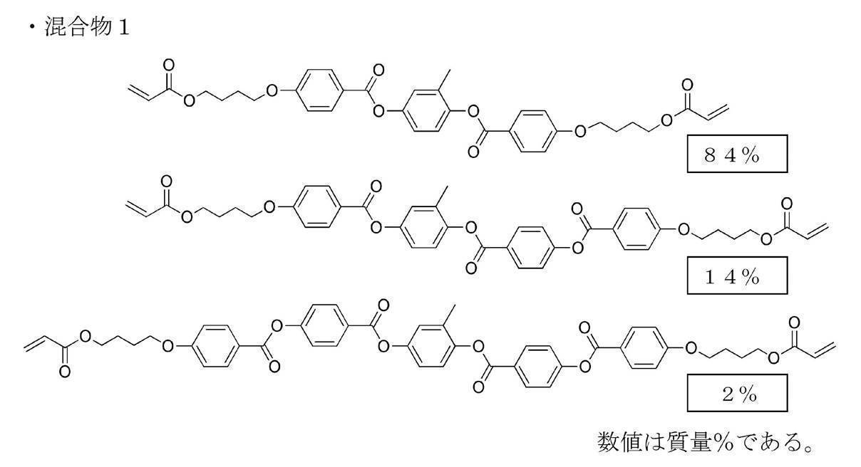


上述の塗布液組成の右旋回性キラル剤LC756の処方量を調整してコレステリック液晶層形成用塗布液1およびコレステリック液晶層形成用塗布液2を調製した。コレステリック液晶層形成用塗布液1、またはコレステリック液晶層形成用塗布液2を用いて、以下に示すハーフミラー作製時と同様に仮支持体上に膜厚3μmの単一層のコレステリック液晶層を作製し、可視域光の反射特性を確認したところ、作製されたコレステリック液晶層は全て右円偏光反射層であり、中心反射波長は塗布液1は波長580nm、塗布液2は波長700nmであった。
(位相差層形成用塗布液)
下記の成分を混合し、下記組成の位相差層形成用塗布液を調製した。
下記の成分を混合し、下記組成の位相差層形成用塗布液を調製した。
位相差層形成用塗布液
・混合物1 100質量部
・フッ素系水平配向剤1(配向制御剤1) 0.05質量部
・フッ素系水平配向剤2(配向制御剤2) 0.01質量部
・重合開始剤IRGACURE OXE01(BASF社製)
1.0質量部
・溶媒(メチルエチルケトン) 溶質濃度が20質量%となる量
・混合物1 100質量部
・フッ素系水平配向剤1(配向制御剤1) 0.05質量部
・フッ素系水平配向剤2(配向制御剤2) 0.01質量部
・重合開始剤IRGACURE OXE01(BASF社製)
1.0質量部
・溶媒(メチルエチルケトン) 溶質濃度が20質量%となる量
(偏光変換層形成用塗布液)
下記の成分を混合し、下記組成の偏光変換層形成用塗布液を調製した。
下記の成分を混合し、下記組成の偏光変換層形成用塗布液を調製した。
偏光変換層形成用塗布液
・混合物1 100質量部
・フッ素系水平配向剤1(下記配向制御剤1) 0.05質量部
・フッ素系水平配向剤2(下記配向制御剤2) 0.02質量部
・右旋回性キラル剤LC756(BASF社製)
目標のピッチ数と膜厚に合う反射波長に合わせて調整
・重合開始剤IRGACURE OXE01(BASF社製)
1.0質量部
・溶媒(メチルエチルケトン) 溶質濃度が20質量%となる量
・混合物1 100質量部
・フッ素系水平配向剤1(下記配向制御剤1) 0.05質量部
・フッ素系水平配向剤2(下記配向制御剤2) 0.02質量部
・右旋回性キラル剤LC756(BASF社製)
目標のピッチ数と膜厚に合う反射波長に合わせて調整
・重合開始剤IRGACURE OXE01(BASF社製)
1.0質量部
・溶媒(メチルエチルケトン) 溶質濃度が20質量%となる量
上述の塗布液組成の右旋回性キラル剤LC756の処方量を調整して所望の反射中心波長λとなるように偏光変換層形成用塗布液を調製した。螺旋構造の膜厚dがピッチ(反射中心波長λ/面内の平均屈折率n)×ピッチ数の関係式で表せることから、膜厚とピッチ数を特定し、λを決定した。ピッチ数は、仮支持体上に所望の膜厚の単一層のコレステリック液晶層を作製し、AxoScan(アクソメトリクス社製)の測定値をフィッティングして得られたツイスト角(ピッチ数×360°)から求めた。
表1に、調整した偏光変換層形成用塗布液の目標となる偏光変換層のピッチ数、膜厚、λの組み合わせを示す。
表1に、調整した偏光変換層形成用塗布液の目標となる偏光変換層のピッチ数、膜厚、λの組み合わせを示す。

<セルロースアシレートフィルムの鹸化>
国際公開第2014/112575号の実施例20と同一の作製方法で得られた40μmセルロースアシレートフィルムを、温度60℃の誘電式加熱ロールを通過させ、フィルム表面温度を40℃に昇温した後に、フィルムの片面に下記に示す組成のアルカリ溶液を、バーコーターを用いて塗布量14mL/m2で塗布し、110℃に加熱したスチーム式遠赤外ヒーター(ノリタケカンパニーリミテド社製)の下に10秒間滞留させた。
次いで、同じくバーコーターを用いて、純水を3mL/m2塗布した。
次いで、ファウンテンコーターによる水洗とエアナイフによる水切りを3回繰り返した後に、70℃の乾燥ゾーンに5秒間滞留させて乾燥し、鹸化処理したセルロースアシレートフィルム1を作製した。
セルロースアシレートフィルム1の面内位相差をAxoScanで測定したところ、1nmであった。
――――――――――――――――――――――――――――――――――
アルカリ溶液の組成
――――――――――――――――――――――――――――――――――
・水酸化カリウム 4.7質量部
・水 15.7質量部
・イソプロパノール 64.8質量部
・界面活性剤(C16H33O(CH2CH2O)10H) 1.0質量部
・プロピレングリコール 14.9質量部
――――――――――――――――――――――――――――――――――
アルカリ溶液の組成
――――――――――――――――――――――――――――――――――
・水酸化カリウム 4.7質量部
・水 15.7質量部
・イソプロパノール 64.8質量部
・界面活性剤(C16H33O(CH2CH2O)10H) 1.0質量部
・プロピレングリコール 14.9質量部
――――――――――――――――――――――――――――――――――
<配向膜の形成>
上述で得られた鹸化処理したセルロースアシレートフィルム1(透明支持体)の鹸化処理面に、下記に示す組成の配向膜形成用塗布液を、ワイヤーバーコーターで24mL/m2塗布し、100℃の温風で120秒乾燥した。
上述で得られた鹸化処理したセルロースアシレートフィルム1(透明支持体)の鹸化処理面に、下記に示す組成の配向膜形成用塗布液を、ワイヤーバーコーターで24mL/m2塗布し、100℃の温風で120秒乾燥した。
――――――――――――――――――――――――――――――――――
配向膜形成用塗布液の組成
――――――――――――――――――――――――――――――――――
・下記に示す変性ポリビニルアルコール 28質量部
・クエン酸エステル(AS3、三共化学社製) 1.2質量部
・光開始剤(イルガキュア2959、BASF社製) 0.84質量部
・グルタルアルデヒド 2.8質量部
・水 699質量部
・メタノール 226質量部
――――――――――――――――――――――――――――――――――
配向膜形成用塗布液の組成
――――――――――――――――――――――――――――――――――
・下記に示す変性ポリビニルアルコール 28質量部
・クエン酸エステル(AS3、三共化学社製) 1.2質量部
・光開始剤(イルガキュア2959、BASF社製) 0.84質量部
・グルタルアルデヒド 2.8質量部
・水 699質量部
・メタノール 226質量部
――――――――――――――――――――――――――――――――――
(変性ポリビニルアルコール)

<ハーフミラーの作製>
(1)支持体として、前述の配向膜を形成したセルロースアシレートフィルム1を使用し、その片面に、塗布面から見て支持体の長手方向を基準に時計回りに回転させた方向(図2におけるα:回転角度、H:長辺方向、Sa:ラビング方向)にラビング処理(レーヨン布、圧力:0.1kgf(0.98N)、回転数:1000rpm(revolutions per minute)、搬送速度:10m/min、回数:1往復)を施した。
実施例1~4および比較例1~4のラビング処理時に回転させた角度を表2に示す。
(1)支持体として、前述の配向膜を形成したセルロースアシレートフィルム1を使用し、その片面に、塗布面から見て支持体の長手方向を基準に時計回りに回転させた方向(図2におけるα:回転角度、H:長辺方向、Sa:ラビング方向)にラビング処理(レーヨン布、圧力:0.1kgf(0.98N)、回転数:1000rpm(revolutions per minute)、搬送速度:10m/min、回数:1往復)を施した。
実施例1~4および比較例1~4のラビング処理時に回転させた角度を表2に示す。
実施例1~4および比較例3は、
(2)セルロースアシレートフィルム1上の配向膜のラビングした表面に第1の偏光変換層形成用塗布液をワイヤーバーを用いて塗布後、乾燥させて50℃のホットプレート上に置き、酸素濃度1000ppm以下の環境にてフュージョンUVシステムズ株式会社製無電極ランプ「Dバルブ」(60mW/cm2)にて6秒間UV照射し、液晶相を固定して、第1の偏光変換層を得た。このとき、第1の偏光変換層のピッチ数、膜厚、λをAxoScan(アクソメトリクス社製)から解析したところ、表1と同様であった。
(2)セルロースアシレートフィルム1上の配向膜のラビングした表面に第1の偏光変換層形成用塗布液をワイヤーバーを用いて塗布後、乾燥させて50℃のホットプレート上に置き、酸素濃度1000ppm以下の環境にてフュージョンUVシステムズ株式会社製無電極ランプ「Dバルブ」(60mW/cm2)にて6秒間UV照射し、液晶相を固定して、第1の偏光変換層を得た。このとき、第1の偏光変換層のピッチ数、膜厚、λをAxoScan(アクソメトリクス社製)から解析したところ、表1と同様であった。
このうち、実施例1~3および比較例3は、
得られた第1の偏光変換層の表面に、コレステリック液晶層形成用塗布液1を乾燥後の乾膜の厚みが0.65μmになるようにワイヤーバーを用いて室温にて塗布して塗布層を得た。溶媒について、固形分濃度が25質量%になるように溶媒量を調整した。塗布層を室温にて30秒間乾燥させた後、85℃の雰囲気で2分間加熱し、その後、酸素濃度1000ppm以下の環境にて60℃でフュージョン製Dバルブ(90mW/cmのランプ)にて出力60%で6~12秒間UV(ultraviolet)照射し、コレステリック液晶相を固定して、厚み0.65μmのコレステリック液晶層を得た。このコレステリック液晶層が第1の選択反射層に相当する。
得られた第1の偏光変換層の表面に、コレステリック液晶層形成用塗布液1を乾燥後の乾膜の厚みが0.65μmになるようにワイヤーバーを用いて室温にて塗布して塗布層を得た。溶媒について、固形分濃度が25質量%になるように溶媒量を調整した。塗布層を室温にて30秒間乾燥させた後、85℃の雰囲気で2分間加熱し、その後、酸素濃度1000ppm以下の環境にて60℃でフュージョン製Dバルブ(90mW/cmのランプ)にて出力60%で6~12秒間UV(ultraviolet)照射し、コレステリック液晶相を固定して、厚み0.65μmのコレステリック液晶層を得た。このコレステリック液晶層が第1の選択反射層に相当する。
次に、得られたコレステリック液晶層の表面にさらにコレステリック液晶層形成用塗布液2を用いて同様の工程を繰り返し、厚み0.71μmのコレステリック液晶層形成用塗布液1の層を積層した。コレステリック液晶層形成用塗布液1の層が第1の選択反射層に相当し、コレステリック液晶層形成用塗布液2の層が第2の選択反射層に相当する。
このようにして第1の偏光変換層と、2層のコレステリック液晶層を備える選択反射層とを含む機能層を備える積層体Aを有する支持体付ハーフミラーを得た。積層体Aから得られた支持体付ハーフミラーの反射スペクトルを分光光度計(日本分光株式会社製、V-670)で測定したところ、波長580nmと波長700nmに選択反射中心波長を有する反射スペクトルが得られた。
次に、得られたコレステリック液晶層(第2の選択反射層)の表面にさらに表1に示した第2の偏光変換層形成用塗布液を用いて各々、目標の膜厚となるように偏光変換層2を形成した。
実施例4については、実施例1~3の2層のコレステリック液晶層のかわりに、直線偏光反射板を用いた。直線偏光反射板としては、特表平9-506837号公報に記載された方法に基づいて、選択反射中心波長が670nmになるように2,6-ポリエチレンナフタレート(PEN)とナフタレート70/テレフタレート30のコポリエステル(coPEN)の各層の厚みを調整して作製したものを用いた。実施例1~3と同様にセルロースアシレートフィルム上の配向膜のラビングした表面に第1の偏光変換層、第2の偏光変換層をそれぞれ作製し、第1の偏光変換層、直線偏光板、第2の偏光変換層をこの順番でDIC株式会社製UV硬化型接着剤Exp.U12034-6を用いて隣接する層と接着した。
比較例1、2については、
(2)セルロースアシレートフィルム1上の配向膜のラビングした表面に位相差層形成用塗布液をワイヤーバーを用いて塗布後、乾燥させて50℃のホットプレート上に置き、酸素濃度1000ppm以下の環境にてフュージョンUVシステムズ株式会社製無電極ランプ「Dバルブ」(60mW/cm2)にて6秒間UV照射し、液晶相を固定して、所望の正面位相差、すなわち、所望のレタデーションとなるように厚みを整除した位相差層を得た。このとき、位相差層のレタデーションをAxoScan(アクソメトリクス社製)で測定したところ、142nmであった。
(2)セルロースアシレートフィルム1上の配向膜のラビングした表面に位相差層形成用塗布液をワイヤーバーを用いて塗布後、乾燥させて50℃のホットプレート上に置き、酸素濃度1000ppm以下の環境にてフュージョンUVシステムズ株式会社製無電極ランプ「Dバルブ」(60mW/cm2)にて6秒間UV照射し、液晶相を固定して、所望の正面位相差、すなわち、所望のレタデーションとなるように厚みを整除した位相差層を得た。このとき、位相差層のレタデーションをAxoScan(アクソメトリクス社製)で測定したところ、142nmであった。
得られた位相差層の表面に、実施例1~3と同様に、2層のコレステリック液晶層を形成した。比較例2については、さらに第2の偏光変換層を形成した。
比較例4については、第1の偏光変換層、第2の偏光変換層がないこと以外は実施例4と同様に作製した。
表2に示すように実施例1~4および比較例1~4の支持体付ハーフミラーを作製した。
得られた長尺状の各ハーフミラーについて長手方向280mm×幅手方向250mmのサイズに切断し、シート状のハーフミラーを得た。
得られた長尺状の各ハーフミラーについて長手方向280mm×幅手方向250mmのサイズに切断し、シート状のハーフミラーを得た。
<合わせガラスの作製>
縦300mm×横300mm厚み2mmのガラス板(セントラル硝子社製、FL2、可視光線透過率90%)の上に同じサイズにカッティングした積水化学社製の厚み0.38mmのPVBフィルム(中間膜)を設置した。その上にシート状の各ハーフミラーを、第1の偏光変換層側を上面にして設置し、その上に縦300mm×横300mm厚み2mmのガラス板(セントラル硝子社製、FL2、可視光線透過率90%)を設置した。これを90℃、10kPa(0.1気圧)下で一時間保持した後に、オートクレーブ(栗原製作所製)にて115℃、1.3MPa(13気圧)で20分間加熱して気泡を除去し、合わせガラスを得た。横から見た合わせガラスの構成を図5に示す。第1の偏光変換層側から見たラビング方向Saとの関係を図6に示す。図6における上側をラビングの起点側、下側をラビングの終点側とした。
縦300mm×横300mm厚み2mmのガラス板(セントラル硝子社製、FL2、可視光線透過率90%)の上に同じサイズにカッティングした積水化学社製の厚み0.38mmのPVBフィルム(中間膜)を設置した。その上にシート状の各ハーフミラーを、第1の偏光変換層側を上面にして設置し、その上に縦300mm×横300mm厚み2mmのガラス板(セントラル硝子社製、FL2、可視光線透過率90%)を設置した。これを90℃、10kPa(0.1気圧)下で一時間保持した後に、オートクレーブ(栗原製作所製)にて115℃、1.3MPa(13気圧)で20分間加熱して気泡を除去し、合わせガラスを得た。横から見た合わせガラスの構成を図5に示す。第1の偏光変換層側から見たラビング方向Saとの関係を図6に示す。図6における上側をラビングの起点側、下側をラビングの終点側とした。
[可視光線透過率の評価]
可視光線透過率として、JIS R 3212:2015(自動車用安全ガラス試験方法)において定められたA光源可視光線透過率を求めた。可視光線透過率の評価は、下記評価基準にて評価した。可視光線透過率の結果を下記表3に示す。
可視光線透過率として、JIS R 3212:2015(自動車用安全ガラス試験方法)において定められたA光源可視光線透過率を求めた。可視光線透過率の評価は、下記評価基準にて評価した。可視光線透過率の結果を下記表3に示す。
可視光線透過率の評価基準
A:83%以上
B:80%以上~83%未満
C:80%未満
A:83%以上
B:80%以上~83%未満
C:80%未満
[輝度の評価]
第1の偏光変換層側のガラス面から合わせガラスの法線方向に対し65°の方向からp偏光を入射し、その正反射光(入射面内で法線方向に対して入射方向と反対側の、法線方向に対し65°の方向)を分光光度計(日本分光株式会社製、V-670)で反射率スペクトルを測定した。このとき、ハーフミラーの長辺方向と分光光度計の入射するp偏光の透過軸とを平行にした。この時、合わせガラスの軸Hと上下方向Yは同じ方向となり、ガラスの上側がラビングの起点側となる(図7参照)。観察したJIS R3106に従って、380~780nmでの10nm毎の波長において、反射率に視感度に応じた係数および一般的な液晶表示装置の発光スペクトルをそれぞれ乗じて投映像反射率を計算し、輝度として評価した。輝度の評価は、下記評価基準にて評価した。輝度の結果を下記表3に示す。
第1の偏光変換層側のガラス面から合わせガラスの法線方向に対し65°の方向からp偏光を入射し、その正反射光(入射面内で法線方向に対して入射方向と反対側の、法線方向に対し65°の方向)を分光光度計(日本分光株式会社製、V-670)で反射率スペクトルを測定した。このとき、ハーフミラーの長辺方向と分光光度計の入射するp偏光の透過軸とを平行にした。この時、合わせガラスの軸Hと上下方向Yは同じ方向となり、ガラスの上側がラビングの起点側となる(図7参照)。観察したJIS R3106に従って、380~780nmでの10nm毎の波長において、反射率に視感度に応じた係数および一般的な液晶表示装置の発光スペクトルをそれぞれ乗じて投映像反射率を計算し、輝度として評価した。輝度の評価は、下記評価基準にて評価した。輝度の結果を下記表3に示す。
輝度の評価基準
A:35%以上
B:25%以上~35%未満
C:25%未満
A:35%以上
B:25%以上~35%未満
C:25%未満
[二重像の評価]
合わせガラスの第2の偏光変換層側のガラス面側に黒PET(吸収材料)を貼付し、輝度の評価と同様に、偏光変換層1側のガラス面の法線方向に対し65°の方向からp偏光を入射し、その正反射光を分光光度計(日本分光株式会社製、V-670)で反射率スペクトルを測定した。
二重像は、合わせガラスの裏面の反射と輝度の比率として、(輝度-黒PET貼付した輝度)/輝度 として評価した。二重像の結果を下記表3に示す。
合わせガラスの第2の偏光変換層側のガラス面側に黒PET(吸収材料)を貼付し、輝度の評価と同様に、偏光変換層1側のガラス面の法線方向に対し65°の方向からp偏光を入射し、その正反射光を分光光度計(日本分光株式会社製、V-670)で反射率スペクトルを測定した。
二重像は、合わせガラスの裏面の反射と輝度の比率として、(輝度-黒PET貼付した輝度)/輝度 として評価した。二重像の結果を下記表3に示す。
二重像の評価基準
A:4%未満
B:4%以上~7%未満
C:7%以上
A:4%未満
B:4%以上~7%未満
C:7%以上
[偏光サングラス適性の評価]
合わせガラスの第2の偏光変換層側のガラス面から合わせガラスの法線方向に対し65°方向からs偏光を入射し、合わせガラスの入射面の反対面側から透過光のp偏光を分光光度計(日本分光株式会社製、V-670)で透過率スペクトルを測定した。
このとき分光光度計の受光部に直線偏光板を配置して、ハーフミラーの長辺方向と分光光度計の入射するp偏光の透過軸とを平行にした(図8参照)。観察したJIS R3106に従って、380~780nmでの10nm毎の波長において、視感度に応じた係数およびD65光源の発光スペクトルをそれぞれ乗じて可視光線透過率を計算し、偏光サングラス適性として評価した。偏光サングラス適性の評価は、下記評価基準にて評価した。輝度の結果を下記表3に示す。
偏光サングラス適性の評価基準
A:3%未満
B:3%以上~5%未満
C:5%以上
A:3%未満
B:3%以上~5%未満
C:5%以上
[外側から斜めに入射する光の偏光サングラス適性の評価]
上述の偏光サングラス適性の評価において、図8の軸43を中心に合わせガラスを20°、40°に回転した状態で同様に評価した。偏光サングラス適性の評価は、下記評価基準にて評価した。輝度の結果を下記表3に示す。
上述の偏光サングラス適性の評価において、図8の軸43を中心に合わせガラスを20°、40°に回転した状態で同様に評価した。偏光サングラス適性の評価は、下記評価基準にて評価した。輝度の結果を下記表3に示す。
偏光サングラス適性の評価基準
A:3%未満
B:3%以上~5%未満
C:5%以上
A:3%未満
B:3%以上~5%未満
C:5%以上

表2および表3に示すように、実施例1~4は、比較例1~4に比して、輝度、二重像、斜め光に対する偏光サングラス適性について良好な結果が得られており、可視光線透過率、輝度、二重像、偏光サングラス適性の鼎立を図ることができた。
比較例1~2および比較例4は、偏光変換層が2つなく、斜め光の偏光サングラス適性の評価結果が悪かった。
比較例3は、偏光変換層の膜厚およびピッチ数が適切でなく、二重像と偏光サングラス適性の評価結果が悪かった。
比較例1~2および比較例4は、偏光変換層が2つなく、斜め光の偏光サングラス適性の評価結果が悪かった。
比較例3は、偏光変換層の膜厚およびピッチ数が適切でなく、二重像と偏光サングラス適性の評価結果が悪かった。
10 投映像表示用部材
11 第2の偏光変換層
12 選択反射層
12G 第1の選択反射層
12R 第2の選択反射層
14 第1の偏光変換層
15 支持体
20 ヘッドアップディスプレイシステム(HUD)
22 プロジェクター
24 ウインドシールドガラス
25、30a 表面
28 第1のガラス板
30 第2のガラス板
36 中間膜
38 接着剤層
40 分光光度計光源
41 分光光度計ディテクタ
42 直線偏光板
43 測定時の回転方向
D 運転者
H 軸
Sa 遅相軸
Y 上下方向
11 第2の偏光変換層
12 選択反射層
12G 第1の選択反射層
12R 第2の選択反射層
14 第1の偏光変換層
15 支持体
20 ヘッドアップディスプレイシステム(HUD)
22 プロジェクター
24 ウインドシールドガラス
25、30a 表面
28 第1のガラス板
30 第2のガラス板
36 中間膜
38 接着剤層
40 分光光度計光源
41 分光光度計ディテクタ
42 直線偏光板
43 測定時の回転方向
D 運転者
H 軸
Sa 遅相軸
Y 上下方向
Claims (5)
- 第1の偏光変換層、少なくとも1層の選択反射層、第2の偏光変換層をこの順に有する投映像表示用部材であって、
前記第1の偏光変換層と前記第2の偏光変換層とが、液晶化合物の螺旋配向構造を固定化した層であって、前記螺旋配向構造のピッチ数および膜厚が下記関係式全てを満足する投映像表示用部材。
前記第1の偏光変換層のピッチ数をx1、膜厚をy1(単位μm)とした場合
(i) 0.3≦x1≦2.0
(ii) y1≧1.86x1+0.13
前記第2の偏光変換層のピッチ数をx2、膜厚をy2(単位μm)とした場合
(iii) 0.25≦x2≦2.0
(iv) y2≦1.37x2+5.5
(v)y2≧1.37x2+0.25 - 前記選択反射層が、直線偏光反射性の反射層である請求項1に記載の投影像表示用部材。
- 前記選択反射層が、円偏光反射性の反射層である請求項1に記載の投影像表示用部材。
- 第1のガラス板および第2のガラス板の間に、請求項1~3のいずれか1項に記載の投映像表示用部材を有するウインドシールドガラス。
- 請求項4に記載のウインドシールドガラスを有し、さらに前記ウインドシールドガラスの前記第1の偏光変換層側からp偏光の投映画像光を照射するプロジェクターを有するヘッドアップディスプレイシステム。
Priority Applications (3)
| Application Number | Priority Date | Filing Date | Title |
|---|---|---|---|
| EP19894588.3A EP3895927A4 (en) | 2018-12-10 | 2019-12-09 | PROJECTION IMAGE DISPLAY ELEMENT, WINDSHIELD GLASS AND HEAD-UP DISPLAY SYSTEM |
| JP2020560099A JP7299920B2 (ja) | 2018-12-10 | 2019-12-09 | 投映像表示用部材、ウインドシールドガラスおよびヘッドアップディスプレイシステム |
| US17/343,160 US11947109B2 (en) | 2018-12-10 | 2021-06-09 | Projection image-displaying member, windshield glass, and head-up display system |
Applications Claiming Priority (2)
| Application Number | Priority Date | Filing Date | Title |
|---|---|---|---|
| JP2018-231008 | 2018-12-10 | ||
| JP2018231008 | 2018-12-10 |
Related Child Applications (1)
| Application Number | Title | Priority Date | Filing Date |
|---|---|---|---|
| US17/343,160 Continuation US11947109B2 (en) | 2018-12-10 | 2021-06-09 | Projection image-displaying member, windshield glass, and head-up display system |
Publications (1)
| Publication Number | Publication Date |
|---|---|
| WO2020122023A1 true WO2020122023A1 (ja) | 2020-06-18 |
Family
ID=71077272
Family Applications (1)
| Application Number | Title | Priority Date | Filing Date |
|---|---|---|---|
| PCT/JP2019/048114 WO2020122023A1 (ja) | 2018-12-10 | 2019-12-09 | 投映像表示用部材、ウインドシールドガラスおよびヘッドアップディスプレイシステム |
Country Status (4)
| Country | Link |
|---|---|
| US (1) | US11947109B2 (ja) |
| EP (1) | EP3895927A4 (ja) |
| JP (1) | JP7299920B2 (ja) |
| WO (1) | WO2020122023A1 (ja) |
Cited By (3)
| Publication number | Priority date | Publication date | Assignee | Title |
|---|---|---|---|---|
| WO2021200433A1 (ja) * | 2020-03-30 | 2021-10-07 | 富士フイルム株式会社 | ウインドシールドガラスおよびヘッドアップディスプレイシステム |
| WO2021200655A1 (ja) * | 2020-03-30 | 2021-10-07 | 富士フイルム株式会社 | 反射フィルム、ウインドシールドガラスおよびヘッドアップディスプレイシステム |
| WO2022123946A1 (ja) * | 2020-12-09 | 2022-06-16 | 富士フイルム株式会社 | 反射フィルム、ウインドシールドガラスおよびヘッドアップディスプレイシステム |
Families Citing this family (4)
| Publication number | Priority date | Publication date | Assignee | Title |
|---|---|---|---|---|
| JP2021071604A (ja) * | 2019-10-31 | 2021-05-06 | セイコーエプソン株式会社 | 導光装置、表示装置及び導光装置の製法方法 |
| CN111812904B (zh) * | 2020-07-15 | 2022-08-16 | 深圳市国华光电科技有限公司 | 一种液晶多层膜及其制备方法 |
| US11467401B2 (en) * | 2021-03-02 | 2022-10-11 | GM Global Technology Operations LLC | Display and light blocking screens |
| US11493791B2 (en) | 2021-03-02 | 2022-11-08 | GM Global Technology Operations LLC | Display and light blocking screens |
Citations (81)
| Publication number | Priority date | Publication date | Assignee | Title |
|---|---|---|---|---|
| US2367661A (en) | 1941-12-31 | 1945-01-23 | Du Pont | Process of photopolymerization |
| US2367670A (en) | 1941-12-31 | 1945-01-23 | Du Pont | Cementing process |
| US2448828A (en) | 1946-09-04 | 1948-09-07 | Du Pont | Photopolymerization |
| US2722512A (en) | 1952-10-23 | 1955-11-01 | Du Pont | Photopolymerization process |
| US2951758A (en) | 1957-05-17 | 1960-09-06 | Du Pont | Photopolymerizable compositions and elements |
| US3046127A (en) | 1957-10-07 | 1962-07-24 | Du Pont | Photopolymerizable compositions, elements and processes |
| US3549367A (en) | 1968-05-24 | 1970-12-22 | Du Pont | Photopolymerizable compositions containing triarylimidazolyl dimers and p-aminophenyl ketones |
| US4212970A (en) | 1977-11-28 | 1980-07-15 | Fuji Photo Film Co., Ltd. | 2-Halomethyl-5-vinyl-1,3,4-oxadiazole compounds |
| US4239850A (en) | 1977-11-29 | 1980-12-16 | Fuji Photo Film Co., Ltd. | Photopolymerizable composition |
| JPS60105667A (ja) | 1983-10-12 | 1985-06-11 | ヘキスト・アクチエンゲゼルシヤフト | トリクロルメチル基を有する感光性化合物及びその製法 |
| US4683327A (en) | 1985-06-24 | 1987-07-28 | Celanese Corporation | Anisotropic heat-curable acrylic terminated monomers |
| JPS6340799B2 (ja) | 1978-07-14 | 1988-08-12 | Basf Ag | |
| JPH01272551A (ja) | 1988-04-22 | 1989-10-31 | Dainippon Printing Co Ltd | 重合性2官能アクリレートモノマー |
| JPH02141720A (ja) | 1988-11-23 | 1990-05-31 | Nippon Denso Co Ltd | ヘッドアップディスプレイ装置 |
| US5013134A (en) | 1989-09-28 | 1991-05-07 | Hughes Aircraft Company | Ghost-free automotive head-up display employing a wedged windshield |
| JPH0529234A (ja) | 1991-07-25 | 1993-02-05 | Fujitsu Ltd | エピタキシヤル成長法 |
| JPH0529234B2 (ja) | 1984-11-27 | 1993-04-28 | Esupe Fuaburiiku Fuarumatsuoiteitsusheru Pureparaate Gmbh Unto Co Kg | |
| JPH0616616A (ja) | 1992-07-03 | 1994-01-25 | Canon Inc | 反応性液晶性化合物、高分子液晶化合物、液晶組成物および液晶素子 |
| JPH07110469A (ja) | 1993-08-16 | 1995-04-25 | Dainippon Ink & Chem Inc | 液晶表示素子及びその製造方法 |
| WO1995020180A1 (en) * | 1994-01-25 | 1995-07-27 | Fergason James L | Display system and method |
| WO1995022586A1 (de) | 1994-02-19 | 1995-08-24 | Basf Aktiengesellschaft | Neue polymerisierbare flüssigkristalline verbindungen |
| WO1995024455A1 (de) | 1994-03-11 | 1995-09-14 | Basf Aktiengesellschaft | Neue polymerisierbare flüssigkristalline verbindungen |
| JPH07270711A (ja) | 1994-03-30 | 1995-10-20 | Canon Inc | 情報表示装置 |
| WO1997000600A2 (de) | 1995-09-01 | 1997-01-09 | Basf Aktiengesellschaft | Polymerisierbare flüssigkristalline verbindungen |
| US5622648A (en) | 1993-10-15 | 1997-04-22 | Merck Patent Gesellschaft Mit Beschrankter Haftung | Reactive liquid crystal compounds |
| JPH09506837A (ja) | 1993-12-21 | 1997-07-08 | ミネソタ・マイニング・アンド・マニュファクチュアリング・カンパニー | 多層光学フィルム |
| JPH1029997A (ja) | 1996-03-04 | 1998-02-03 | Ciba Specialty Chem Holding Inc | アルキルフェニルビスアシルホスフィンオキサイドおよび光開始剤混合物 |
| JPH1096874A (ja) | 1996-05-24 | 1998-04-14 | Asahi Glass Co Ltd | 車両用ウインドシールドガラスおよびヘッドアップディスプレイ装置 |
| JPH1095788A (ja) | 1996-08-28 | 1998-04-14 | Ciba Specialty Chem Holding Inc | 光開始剤としての分子錯化合物 |
| WO1998023580A1 (de) | 1996-11-27 | 1998-06-04 | Basf Aktiengesellschaft | Polymerisierbare oligomesogene |
| US5770107A (en) | 1995-10-05 | 1998-06-23 | Merck Patent Gesellschaft Mit Beschrankter Haftung | Reactive liquid crystalline compound |
| WO1998052905A1 (en) | 1997-05-22 | 1998-11-26 | Rolic Ag | New polymerisable liquid crystalline compounds |
| JPH1180081A (ja) | 1997-09-05 | 1999-03-23 | Dainippon Ink & Chem Inc | 液晶性(メタ)アクリレート化合物と組成物及びこれを用いた光学異方体 |
| JP2000066385A (ja) | 1998-08-18 | 2000-03-03 | Ciba Specialty Chem Holding Inc | 高感度で高レジスト厚さのi線ホトレジスト用スルホニルオキシム類 |
| JP2000080068A (ja) | 1998-06-26 | 2000-03-21 | Ciba Specialty Chem Holding Inc | 新規o―アシルオキシム光開始剤 |
| JP2000221449A (ja) | 1999-01-29 | 2000-08-11 | Arisawa Mfg Co Ltd | 映像装置 |
| JP2001233842A (ja) | 1999-12-15 | 2001-08-28 | Ciba Specialty Chem Holding Inc | オキシムエステルの光開始剤 |
| JP2001328973A (ja) | 2000-03-13 | 2001-11-27 | Fuji Photo Film Co Ltd | 重合性液晶化合物および光学異方性素子 |
| JP2002080478A (ja) | 2000-06-27 | 2002-03-19 | Fuji Photo Film Co Ltd | 光反応型光学活性化合物、光反応型カイラル剤、液晶組成物、液晶カラーフィルタ、光学フィルム、記録媒体、及び液晶の捻れ構造を変化させる方法 |
| JP2002080851A (ja) | 2000-06-27 | 2002-03-22 | Fuji Photo Film Co Ltd | 光反応型カイラル剤、液晶組成物、液晶カラーフィルタ、光学フィルム、記録媒体、及び液晶の捻れ構造を変化させる方法 |
| JP2002302487A (ja) | 2000-12-14 | 2002-10-18 | Fuji Photo Film Co Ltd | 光学活性化合物、光反応型キラル剤、液晶組成物、液晶の螺旋構造を変化させる方法、液晶の螺旋構造を固定化する方法、液晶カラーフィルター、光学フィルムおよび記録媒体 |
| JP2003098470A (ja) | 2001-09-21 | 2003-04-03 | Asahi Glass Co Ltd | ヘッドアップディスプレイ装置 |
| JP2003287623A (ja) | 2002-01-23 | 2003-10-10 | Nitto Denko Corp | 光学フィルム、その製造方法、およびこれを用いた位相差フィルムならびに偏光板 |
| JP2005148713A (ja) * | 2003-10-23 | 2005-06-09 | Nitto Denko Corp | 光学素子、集光バックライトシステムおよび液晶表示装置 |
| JP2006512622A (ja) | 2002-12-31 | 2006-04-13 | スリーエム イノベイティブ プロパティズ カンパニー | 偏光光源および広角p偏光反射偏光子を備えたヘッドアップディスプレイ |
| JP2006342166A (ja) | 2001-06-11 | 2006-12-21 | Ciba Specialty Chem Holding Inc | 組み合わされた構造を有するオキシムエステルの光開始剤 |
| JP2007523369A (ja) | 2004-02-04 | 2007-08-16 | マイクロビジョン,インク. | 走査ビームヘッドアップ表示装置および関連システム、および方法 |
| JP2007272185A (ja) | 2006-03-10 | 2007-10-18 | Fujifilm Corp | 組成物、位相差板、液晶表示装置、平均チルト角調整剤、平均チルト角の調整方法 |
| JP4223071B2 (ja) | 2006-12-27 | 2009-02-12 | 株式会社Adeka | オキシムエステル化合物及び該化合物を含有する光重合開始剤 |
| JP2009150947A (ja) | 2007-12-19 | 2009-07-09 | Hitachi Ltd | 車両用ヘッドアップディスプレイ装置 |
| JP2010070543A (ja) | 2008-08-18 | 2010-04-02 | Asahi Glass Co Ltd | 二官能重合性化合物、液晶組成物、光学異方性材料および光学素子 |
| JP2010145745A (ja) | 2008-12-18 | 2010-07-01 | Equos Research Co Ltd | 画像形成装置、及び、ヘッドアップディスプレイ装置 |
| JP2010181852A (ja) | 2008-07-14 | 2010-08-19 | Fujifilm Corp | 光学異方性膜、光学異方性膜の製造方法、液晶セル用基板、及び液晶表示装置 |
| WO2010116912A1 (ja) | 2009-04-08 | 2010-10-14 | 国立大学法人東京大学 | トラッキング装置およびこのトラッキング装置を備えたトラッキング顕微鏡並びにトラッキング方法 |
| JP2010262028A (ja) | 2009-04-30 | 2010-11-18 | Nippon Steel Chem Co Ltd | ブラックマトリックス用感光性樹脂組成物 |
| JP2011505330A (ja) | 2007-12-07 | 2011-02-24 | サン−ゴバン グラス フランス | 合わせガラスからなる曲面の車両用フロントガラス |
| JP4725516B2 (ja) | 2004-06-25 | 2011-07-13 | 旭硝子株式会社 | 重合性液晶化合物、液晶組成物、および光学異方性材料 |
| JP2012203237A (ja) | 2011-03-25 | 2012-10-22 | Fujifilm Corp | 光反射性フィルムの製造方法 |
| JP2012208494A (ja) | 2011-03-17 | 2012-10-25 | Fujifilm Corp | 着色感放射線性組成物、着色硬化膜、カラーフィルタ及びカラーフィルタの製造方法、固体撮像素子、液晶表示装置、並びに、染料の製造方法 |
| JP2012226303A (ja) | 2011-12-21 | 2012-11-15 | Pioneer Electronic Corp | 光源ユニット及びヘッドアップディスプレイ |
| JP2013114249A (ja) | 2011-12-01 | 2013-06-10 | Toppan Printing Co Ltd | 黒色感光性樹脂組成物およびカラーフィルタ |
| JP2013113913A (ja) | 2011-11-25 | 2013-06-10 | Fujifilm Corp | フィルムおよびその製造方法 |
| JP2013112631A (ja) | 2011-11-28 | 2013-06-10 | Dic Corp | 重合性液晶化合物 |
| JP2013228674A (ja) | 2012-03-28 | 2013-11-07 | Nippon Seiki Co Ltd | 車両用表示装置 |
| JP2014500852A (ja) | 2010-10-05 | 2014-01-16 | ビーエーエスエフ ソシエタス・ヨーロピア | ベンゾカルバゾール化合物のオキシムエステル誘導体ならびに前記誘導体の光重合性の組成物における光開始剤としての使用 |
| JP2014034581A (ja) | 2012-08-07 | 2014-02-24 | Fujifilm Corp | 液晶組成物、高分子、フィルムおよびコレステリック液晶 |
| WO2014112575A1 (ja) | 2013-01-18 | 2014-07-24 | 富士フイルム株式会社 | 光学フィルム、偏光板、及び画像表示装置 |
| JP2014137466A (ja) | 2013-01-16 | 2014-07-28 | Jsr Corp | 感放射線性着色組成物、着色硬化膜及び表示素子 |
| WO2015115390A1 (ja) | 2014-01-28 | 2015-08-06 | 富士フイルム株式会社 | 重合性化合物、重合性組成物、フィルム、および投映像表示用ハーフミラー |
| WO2015147243A1 (ja) | 2014-03-28 | 2015-10-01 | 富士フイルム株式会社 | 重合性化合物、ポリマー、重合性組成物、フィルム、および投映像表示用ハーフミラー |
| WO2015190157A1 (ja) | 2014-06-13 | 2015-12-17 | 三菱電機株式会社 | 虚像表示装置 |
| WO2016035873A1 (ja) | 2014-09-05 | 2016-03-10 | 富士フイルム株式会社 | 重合性化合物、ポリマー、重合性組成物、およびフィルム |
| WO2016047648A1 (ja) | 2014-09-25 | 2016-03-31 | 富士フイルム株式会社 | 重合性化合物を含む重合性組成物、フィルム、および投映像表示用ハーフミラー |
| WO2016056617A1 (ja) | 2014-10-10 | 2016-04-14 | 日本化薬株式会社 | 光反射フィルム、ならびにこれを用いた光制御フィルム、光学フィルム、機能性ガラスおよびヘッドアップディスプレイ |
| JP2016053149A (ja) | 2014-03-28 | 2016-04-14 | 富士フイルム株式会社 | 重合性化合物、ポリマー、重合性組成物、フィルム、および投映像表示用ハーフミラー |
| WO2016133187A1 (ja) * | 2015-02-20 | 2016-08-25 | 富士フイルム株式会社 | ウインドシールドガラスおよびヘッドアップディスプレイシステム |
| WO2016133186A1 (ja) * | 2015-02-20 | 2016-08-25 | 富士フイルム株式会社 | コンバイナおよびヘッドアップディスプレイシステム |
| JP2017015902A (ja) | 2015-06-30 | 2017-01-19 | パナソニックIpマネジメント株式会社 | 表示装置、表示方法および表示媒体 |
| JP2017021302A (ja) | 2015-07-15 | 2017-01-26 | 日本精機株式会社 | ヘッドアップディスプレイ |
| JP2017187685A (ja) | 2016-04-07 | 2017-10-12 | 日本化薬株式会社 | 曲面形状の光反射フィルム及びその製造方法、ならびに当該光反射フィルムを用いた光制御フィルム、光学フィルム、機能性ガラスおよびヘッドアップディスプレイ |
| WO2018110066A1 (ja) * | 2016-12-13 | 2018-06-21 | 富士フイルム株式会社 | ウインドシールドガラス、ヘッドアップディスプレイシステム、および積層フィルム |
Family Cites Families (5)
| Publication number | Priority date | Publication date | Assignee | Title |
|---|---|---|---|---|
| US7202926B2 (en) | 2002-08-26 | 2007-04-10 | Dai Nippon Printing Co., Ltd. | Cholesteric reflective retardation optical element with directors at top surface of optical element parallel to those at the bottom surface of the optical element |
| KR100910954B1 (ko) | 2003-10-23 | 2009-08-05 | 닛토덴코 가부시키가이샤 | 광학소자, 집광 백라이트 시스템 및 액정 표시 장치 |
| KR101131983B1 (ko) | 2010-07-28 | 2012-03-29 | 안희경 | 차량속도에 따라 가상 영상정보 이미지의 투영위치를 변화시키는 차량용 헤드업 디스플레이 장치 |
| CN109073809B (zh) | 2016-04-08 | 2022-07-12 | 日本化药株式会社 | 光学层叠结构体和使用该光学层叠结构体的平视显示器系统以及光反射膜 |
| JP6768567B2 (ja) * | 2016-11-04 | 2020-10-14 | 富士フイルム株式会社 | ウインドシールドガラス、ヘッドアップディスプレイシステム、およびハーフミラーフィルム |
-
2019
- 2019-12-09 JP JP2020560099A patent/JP7299920B2/ja active Active
- 2019-12-09 WO PCT/JP2019/048114 patent/WO2020122023A1/ja active Search and Examination
- 2019-12-09 EP EP19894588.3A patent/EP3895927A4/en active Pending
-
2021
- 2021-06-09 US US17/343,160 patent/US11947109B2/en active Active
Patent Citations (83)
| Publication number | Priority date | Publication date | Assignee | Title |
|---|---|---|---|---|
| US2367670A (en) | 1941-12-31 | 1945-01-23 | Du Pont | Cementing process |
| US2367661A (en) | 1941-12-31 | 1945-01-23 | Du Pont | Process of photopolymerization |
| US2448828A (en) | 1946-09-04 | 1948-09-07 | Du Pont | Photopolymerization |
| US2722512A (en) | 1952-10-23 | 1955-11-01 | Du Pont | Photopolymerization process |
| US2951758A (en) | 1957-05-17 | 1960-09-06 | Du Pont | Photopolymerizable compositions and elements |
| US3046127A (en) | 1957-10-07 | 1962-07-24 | Du Pont | Photopolymerizable compositions, elements and processes |
| US3549367A (en) | 1968-05-24 | 1970-12-22 | Du Pont | Photopolymerizable compositions containing triarylimidazolyl dimers and p-aminophenyl ketones |
| US4212970A (en) | 1977-11-28 | 1980-07-15 | Fuji Photo Film Co., Ltd. | 2-Halomethyl-5-vinyl-1,3,4-oxadiazole compounds |
| US4239850A (en) | 1977-11-29 | 1980-12-16 | Fuji Photo Film Co., Ltd. | Photopolymerizable composition |
| JPS6340799B2 (ja) | 1978-07-14 | 1988-08-12 | Basf Ag | |
| JPS60105667A (ja) | 1983-10-12 | 1985-06-11 | ヘキスト・アクチエンゲゼルシヤフト | トリクロルメチル基を有する感光性化合物及びその製法 |
| JPH0529234B2 (ja) | 1984-11-27 | 1993-04-28 | Esupe Fuaburiiku Fuarumatsuoiteitsusheru Pureparaate Gmbh Unto Co Kg | |
| US4683327A (en) | 1985-06-24 | 1987-07-28 | Celanese Corporation | Anisotropic heat-curable acrylic terminated monomers |
| JPH01272551A (ja) | 1988-04-22 | 1989-10-31 | Dainippon Printing Co Ltd | 重合性2官能アクリレートモノマー |
| JPH02141720A (ja) | 1988-11-23 | 1990-05-31 | Nippon Denso Co Ltd | ヘッドアップディスプレイ装置 |
| US5013134A (en) | 1989-09-28 | 1991-05-07 | Hughes Aircraft Company | Ghost-free automotive head-up display employing a wedged windshield |
| JPH0529234A (ja) | 1991-07-25 | 1993-02-05 | Fujitsu Ltd | エピタキシヤル成長法 |
| JPH0616616A (ja) | 1992-07-03 | 1994-01-25 | Canon Inc | 反応性液晶性化合物、高分子液晶化合物、液晶組成物および液晶素子 |
| JPH07110469A (ja) | 1993-08-16 | 1995-04-25 | Dainippon Ink & Chem Inc | 液晶表示素子及びその製造方法 |
| US5622648A (en) | 1993-10-15 | 1997-04-22 | Merck Patent Gesellschaft Mit Beschrankter Haftung | Reactive liquid crystal compounds |
| JPH09506837A (ja) | 1993-12-21 | 1997-07-08 | ミネソタ・マイニング・アンド・マニュファクチュアリング・カンパニー | 多層光学フィルム |
| WO1995020180A1 (en) * | 1994-01-25 | 1995-07-27 | Fergason James L | Display system and method |
| WO1995022586A1 (de) | 1994-02-19 | 1995-08-24 | Basf Aktiengesellschaft | Neue polymerisierbare flüssigkristalline verbindungen |
| WO1995024455A1 (de) | 1994-03-11 | 1995-09-14 | Basf Aktiengesellschaft | Neue polymerisierbare flüssigkristalline verbindungen |
| JPH07270711A (ja) | 1994-03-30 | 1995-10-20 | Canon Inc | 情報表示装置 |
| WO1997000600A2 (de) | 1995-09-01 | 1997-01-09 | Basf Aktiengesellschaft | Polymerisierbare flüssigkristalline verbindungen |
| US5770107A (en) | 1995-10-05 | 1998-06-23 | Merck Patent Gesellschaft Mit Beschrankter Haftung | Reactive liquid crystalline compound |
| JPH1029997A (ja) | 1996-03-04 | 1998-02-03 | Ciba Specialty Chem Holding Inc | アルキルフェニルビスアシルホスフィンオキサイドおよび光開始剤混合物 |
| JPH1096874A (ja) | 1996-05-24 | 1998-04-14 | Asahi Glass Co Ltd | 車両用ウインドシールドガラスおよびヘッドアップディスプレイ装置 |
| JPH1095788A (ja) | 1996-08-28 | 1998-04-14 | Ciba Specialty Chem Holding Inc | 光開始剤としての分子錯化合物 |
| WO1998023580A1 (de) | 1996-11-27 | 1998-06-04 | Basf Aktiengesellschaft | Polymerisierbare oligomesogene |
| WO1998052905A1 (en) | 1997-05-22 | 1998-11-26 | Rolic Ag | New polymerisable liquid crystalline compounds |
| JPH1180081A (ja) | 1997-09-05 | 1999-03-23 | Dainippon Ink & Chem Inc | 液晶性(メタ)アクリレート化合物と組成物及びこれを用いた光学異方体 |
| JP2000080068A (ja) | 1998-06-26 | 2000-03-21 | Ciba Specialty Chem Holding Inc | 新規o―アシルオキシム光開始剤 |
| JP4454067B2 (ja) | 1998-06-26 | 2010-04-21 | チバ ホールディング インコーポレーテッド | 新規o−アシルオキシム光開始剤 |
| JP2000066385A (ja) | 1998-08-18 | 2000-03-03 | Ciba Specialty Chem Holding Inc | 高感度で高レジスト厚さのi線ホトレジスト用スルホニルオキシム類 |
| JP2000221449A (ja) | 1999-01-29 | 2000-08-11 | Arisawa Mfg Co Ltd | 映像装置 |
| JP2001233842A (ja) | 1999-12-15 | 2001-08-28 | Ciba Specialty Chem Holding Inc | オキシムエステルの光開始剤 |
| JP2001328973A (ja) | 2000-03-13 | 2001-11-27 | Fuji Photo Film Co Ltd | 重合性液晶化合物および光学異方性素子 |
| JP2002080478A (ja) | 2000-06-27 | 2002-03-19 | Fuji Photo Film Co Ltd | 光反応型光学活性化合物、光反応型カイラル剤、液晶組成物、液晶カラーフィルタ、光学フィルム、記録媒体、及び液晶の捻れ構造を変化させる方法 |
| JP2002080851A (ja) | 2000-06-27 | 2002-03-22 | Fuji Photo Film Co Ltd | 光反応型カイラル剤、液晶組成物、液晶カラーフィルタ、光学フィルム、記録媒体、及び液晶の捻れ構造を変化させる方法 |
| JP2002302487A (ja) | 2000-12-14 | 2002-10-18 | Fuji Photo Film Co Ltd | 光学活性化合物、光反応型キラル剤、液晶組成物、液晶の螺旋構造を変化させる方法、液晶の螺旋構造を固定化する方法、液晶カラーフィルター、光学フィルムおよび記録媒体 |
| JP2006342166A (ja) | 2001-06-11 | 2006-12-21 | Ciba Specialty Chem Holding Inc | 組み合わされた構造を有するオキシムエステルの光開始剤 |
| JP2003098470A (ja) | 2001-09-21 | 2003-04-03 | Asahi Glass Co Ltd | ヘッドアップディスプレイ装置 |
| JP2003287623A (ja) | 2002-01-23 | 2003-10-10 | Nitto Denko Corp | 光学フィルム、その製造方法、およびこれを用いた位相差フィルムならびに偏光板 |
| JP2006512622A (ja) | 2002-12-31 | 2006-04-13 | スリーエム イノベイティブ プロパティズ カンパニー | 偏光光源および広角p偏光反射偏光子を備えたヘッドアップディスプレイ |
| JP2005148713A (ja) * | 2003-10-23 | 2005-06-09 | Nitto Denko Corp | 光学素子、集光バックライトシステムおよび液晶表示装置 |
| JP2007523369A (ja) | 2004-02-04 | 2007-08-16 | マイクロビジョン,インク. | 走査ビームヘッドアップ表示装置および関連システム、および方法 |
| JP4725516B2 (ja) | 2004-06-25 | 2011-07-13 | 旭硝子株式会社 | 重合性液晶化合物、液晶組成物、および光学異方性材料 |
| JP2007272185A (ja) | 2006-03-10 | 2007-10-18 | Fujifilm Corp | 組成物、位相差板、液晶表示装置、平均チルト角調整剤、平均チルト角の調整方法 |
| JP4223071B2 (ja) | 2006-12-27 | 2009-02-12 | 株式会社Adeka | オキシムエステル化合物及び該化合物を含有する光重合開始剤 |
| JP2011505330A (ja) | 2007-12-07 | 2011-02-24 | サン−ゴバン グラス フランス | 合わせガラスからなる曲面の車両用フロントガラス |
| JP2009150947A (ja) | 2007-12-19 | 2009-07-09 | Hitachi Ltd | 車両用ヘッドアップディスプレイ装置 |
| JP2010181852A (ja) | 2008-07-14 | 2010-08-19 | Fujifilm Corp | 光学異方性膜、光学異方性膜の製造方法、液晶セル用基板、及び液晶表示装置 |
| JP2010070543A (ja) | 2008-08-18 | 2010-04-02 | Asahi Glass Co Ltd | 二官能重合性化合物、液晶組成物、光学異方性材料および光学素子 |
| JP2010145745A (ja) | 2008-12-18 | 2010-07-01 | Equos Research Co Ltd | 画像形成装置、及び、ヘッドアップディスプレイ装置 |
| WO2010116912A1 (ja) | 2009-04-08 | 2010-10-14 | 国立大学法人東京大学 | トラッキング装置およびこのトラッキング装置を備えたトラッキング顕微鏡並びにトラッキング方法 |
| JP2010262028A (ja) | 2009-04-30 | 2010-11-18 | Nippon Steel Chem Co Ltd | ブラックマトリックス用感光性樹脂組成物 |
| JP2014500852A (ja) | 2010-10-05 | 2014-01-16 | ビーエーエスエフ ソシエタス・ヨーロピア | ベンゾカルバゾール化合物のオキシムエステル誘導体ならびに前記誘導体の光重合性の組成物における光開始剤としての使用 |
| JP2012208494A (ja) | 2011-03-17 | 2012-10-25 | Fujifilm Corp | 着色感放射線性組成物、着色硬化膜、カラーフィルタ及びカラーフィルタの製造方法、固体撮像素子、液晶表示装置、並びに、染料の製造方法 |
| JP2012203237A (ja) | 2011-03-25 | 2012-10-22 | Fujifilm Corp | 光反射性フィルムの製造方法 |
| JP2013113913A (ja) | 2011-11-25 | 2013-06-10 | Fujifilm Corp | フィルムおよびその製造方法 |
| JP2013112631A (ja) | 2011-11-28 | 2013-06-10 | Dic Corp | 重合性液晶化合物 |
| JP2013114249A (ja) | 2011-12-01 | 2013-06-10 | Toppan Printing Co Ltd | 黒色感光性樹脂組成物およびカラーフィルタ |
| JP2012226303A (ja) | 2011-12-21 | 2012-11-15 | Pioneer Electronic Corp | 光源ユニット及びヘッドアップディスプレイ |
| JP2013228674A (ja) | 2012-03-28 | 2013-11-07 | Nippon Seiki Co Ltd | 車両用表示装置 |
| JP2014034581A (ja) | 2012-08-07 | 2014-02-24 | Fujifilm Corp | 液晶組成物、高分子、フィルムおよびコレステリック液晶 |
| JP2014137466A (ja) | 2013-01-16 | 2014-07-28 | Jsr Corp | 感放射線性着色組成物、着色硬化膜及び表示素子 |
| WO2014112575A1 (ja) | 2013-01-18 | 2014-07-24 | 富士フイルム株式会社 | 光学フィルム、偏光板、及び画像表示装置 |
| WO2015115390A1 (ja) | 2014-01-28 | 2015-08-06 | 富士フイルム株式会社 | 重合性化合物、重合性組成物、フィルム、および投映像表示用ハーフミラー |
| JP2015163596A (ja) | 2014-01-28 | 2015-09-10 | 富士フイルム株式会社 | 重合性化合物、ポリマー、重合性組成物、フィルム、および投映像表示用ハーフミラー |
| JP2016053149A (ja) | 2014-03-28 | 2016-04-14 | 富士フイルム株式会社 | 重合性化合物、ポリマー、重合性組成物、フィルム、および投映像表示用ハーフミラー |
| WO2015147243A1 (ja) | 2014-03-28 | 2015-10-01 | 富士フイルム株式会社 | 重合性化合物、ポリマー、重合性組成物、フィルム、および投映像表示用ハーフミラー |
| WO2015190157A1 (ja) | 2014-06-13 | 2015-12-17 | 三菱電機株式会社 | 虚像表示装置 |
| WO2016035873A1 (ja) | 2014-09-05 | 2016-03-10 | 富士フイルム株式会社 | 重合性化合物、ポリマー、重合性組成物、およびフィルム |
| WO2016047648A1 (ja) | 2014-09-25 | 2016-03-31 | 富士フイルム株式会社 | 重合性化合物を含む重合性組成物、フィルム、および投映像表示用ハーフミラー |
| WO2016056617A1 (ja) | 2014-10-10 | 2016-04-14 | 日本化薬株式会社 | 光反射フィルム、ならびにこれを用いた光制御フィルム、光学フィルム、機能性ガラスおよびヘッドアップディスプレイ |
| WO2016133187A1 (ja) * | 2015-02-20 | 2016-08-25 | 富士フイルム株式会社 | ウインドシールドガラスおよびヘッドアップディスプレイシステム |
| WO2016133186A1 (ja) * | 2015-02-20 | 2016-08-25 | 富士フイルム株式会社 | コンバイナおよびヘッドアップディスプレイシステム |
| JP2017015902A (ja) | 2015-06-30 | 2017-01-19 | パナソニックIpマネジメント株式会社 | 表示装置、表示方法および表示媒体 |
| JP2017021302A (ja) | 2015-07-15 | 2017-01-26 | 日本精機株式会社 | ヘッドアップディスプレイ |
| JP2017187685A (ja) | 2016-04-07 | 2017-10-12 | 日本化薬株式会社 | 曲面形状の光反射フィルム及びその製造方法、ならびに当該光反射フィルムを用いた光制御フィルム、光学フィルム、機能性ガラスおよびヘッドアップディスプレイ |
| WO2018110066A1 (ja) * | 2016-12-13 | 2018-06-21 | 富士フイルム株式会社 | ウインドシールドガラス、ヘッドアップディスプレイシステム、および積層フィルム |
Non-Patent Citations (4)
| Title |
|---|
| "Ekisho Kagaku Jikken Nyumon (Introduction of Liquid Crystal Chemical Experiments", 2007, SIGMA SHUPPAN, pages: 46 |
| "Liquid Crystal Device Handbook", 1989, article "Chiral Agent for TN and STN", pages: 199 |
| ADVANCED MATERIALS, vol. 5, 1993, pages 107 |
| MAKROMOL. CHEM., vol. 190, 1989, pages 2255 |
Cited By (4)
| Publication number | Priority date | Publication date | Assignee | Title |
|---|---|---|---|---|
| WO2021200433A1 (ja) * | 2020-03-30 | 2021-10-07 | 富士フイルム株式会社 | ウインドシールドガラスおよびヘッドアップディスプレイシステム |
| WO2021200655A1 (ja) * | 2020-03-30 | 2021-10-07 | 富士フイルム株式会社 | 反射フィルム、ウインドシールドガラスおよびヘッドアップディスプレイシステム |
| US11860361B2 (en) | 2020-03-30 | 2024-01-02 | Fujifilm Corporation | Reflection film, windshield glass, and head-up display system |
| WO2022123946A1 (ja) * | 2020-12-09 | 2022-06-16 | 富士フイルム株式会社 | 反射フィルム、ウインドシールドガラスおよびヘッドアップディスプレイシステム |
Also Published As
| Publication number | Publication date |
|---|---|
| US20210294099A1 (en) | 2021-09-23 |
| EP3895927A1 (en) | 2021-10-20 |
| JP7299920B2 (ja) | 2023-06-28 |
| JPWO2020122023A1 (ja) | 2021-11-11 |
| US11947109B2 (en) | 2024-04-02 |
| EP3895927A4 (en) | 2022-02-23 |
Similar Documents
| Publication | Publication Date | Title |
|---|---|---|
| WO2020122023A1 (ja) | 投映像表示用部材、ウインドシールドガラスおよびヘッドアップディスプレイシステム | |
| JP7177176B2 (ja) | 投映像表示用部材、ウインドシールドガラスおよびヘッドアップディスプレイシステム | |
| JP6768567B2 (ja) | ウインドシールドガラス、ヘッドアップディスプレイシステム、およびハーフミラーフィルム | |
| US11314087B2 (en) | Projection image-displaying member, windshield glass, and head-up display system | |
| JP7382392B2 (ja) | 投映像表示用部材、ウインドシールドガラスおよびヘッドアップディスプレイシステム | |
| WO2018084076A1 (ja) | ウインドシールドガラス、ヘッドアップディスプレイシステム、およびハーフミラーフィルム | |
| WO2020179787A1 (ja) | 投映像表示用積層フィルム、投映像表示用の合わせガラス、および、画像表示システム | |
| US20200333598A1 (en) | Method for producing screen image-displaying laminated glass, screen image-displaying laminated glass, and image display system | |
| JP6858113B2 (ja) | 実像表示用部材、および表示システム | |
| JP7313457B2 (ja) | ヘッドアップディスプレイ用プロジェクター | |
| JP7260449B2 (ja) | 投映像表示用部材、ウインドシールドガラスおよびヘッドアップディスプレイシステム | |
| US20230314669A1 (en) | Reflection film, windshield glass, and head-up display system | |
| JP2019012211A (ja) | 投映像表示用ハーフミラー、ウインドシールドガラスおよびヘッドアップディスプレイシステム | |
| US11860361B2 (en) | Reflection film, windshield glass, and head-up display system | |
| JP6676015B2 (ja) | 合わせガラスの製造方法 | |
| WO2021246402A1 (ja) | 反射フィルム、合わせガラスの製造方法、および、合わせガラス | |
| WO2023054324A1 (ja) | ヘッドアップディスプレイシステム及び輸送機 | |
| WO2023080115A1 (ja) | 虚像表示装置、ヘッドアップディスプレイシステム及び輸送機 | |
| WO2023080116A1 (ja) | 反射フィルム、ウインドシールドガラス、ヘッドアップディスプレイシステム及びこのヘッドアップディスプレイシステムを有する輸送機 | |
| JP2021056321A (ja) | プロジェクター用反射部材およびヘッドアップディスプレイ用プロジェクター |
Legal Events
| Date | Code | Title | Description |
|---|---|---|---|
| 121 | Ep: the epo has been informed by wipo that ep was designated in this application |
Ref document number: 19894588 Country of ref document: EP Kind code of ref document: A1 |
|
| DPE1 | Request for preliminary examination filed after expiration of 19th month from priority date (pct application filed from 20040101) | ||
| ENP | Entry into the national phase |
Ref document number: 2020560099 Country of ref document: JP Kind code of ref document: A |
|
| NENP | Non-entry into the national phase |
Ref country code: DE |
|
| ENP | Entry into the national phase |
Ref document number: 2019894588 Country of ref document: EP Effective date: 20210712 |