WO2020179787A1 - 投映像表示用積層フィルム、投映像表示用の合わせガラス、および、画像表示システム - Google Patents
投映像表示用積層フィルム、投映像表示用の合わせガラス、および、画像表示システム Download PDFInfo
- Publication number
- WO2020179787A1 WO2020179787A1 PCT/JP2020/008919 JP2020008919W WO2020179787A1 WO 2020179787 A1 WO2020179787 A1 WO 2020179787A1 JP 2020008919 W JP2020008919 W JP 2020008919W WO 2020179787 A1 WO2020179787 A1 WO 2020179787A1
- Authority
- WO
- WIPO (PCT)
- Prior art keywords
- film
- layer
- laminated
- liquid crystal
- glass
- Prior art date
Links
- 239000005340 laminated glass Substances 0.000 title claims abstract description 131
- 230000003068 static effect Effects 0.000 claims abstract description 30
- 229920005992 thermoplastic resin Polymers 0.000 claims abstract description 10
- 239000010410 layer Substances 0.000 claims description 456
- 239000011521 glass Substances 0.000 claims description 158
- 239000011229 interlayer Substances 0.000 claims description 29
- 239000010419 fine particle Substances 0.000 claims description 27
- 239000011164 primary particle Substances 0.000 claims description 20
- 239000012793 heat-sealing layer Substances 0.000 claims description 17
- 229920002554 vinyl polymer Polymers 0.000 claims description 12
- DHKHKXVYLBGOIT-UHFFFAOYSA-N 1,1-Diethoxyethane Chemical compound CCOC(C)OCC DHKHKXVYLBGOIT-UHFFFAOYSA-N 0.000 claims description 11
- 239000011354 acetal resin Substances 0.000 claims description 11
- 239000002245 particle Substances 0.000 claims description 11
- 229920006324 polyoxymethylene Polymers 0.000 claims description 11
- 239000011163 secondary particle Substances 0.000 claims description 10
- 239000010408 film Substances 0.000 description 357
- 239000004986 Cholesteric liquid crystals (ChLC) Substances 0.000 description 122
- 239000004973 liquid crystal related substance Substances 0.000 description 91
- 150000001875 compounds Chemical class 0.000 description 81
- 239000000203 mixture Substances 0.000 description 54
- 238000000034 method Methods 0.000 description 45
- 229920005989 resin Polymers 0.000 description 38
- 239000011347 resin Substances 0.000 description 38
- 239000011248 coating agent Substances 0.000 description 36
- 238000000576 coating method Methods 0.000 description 36
- 239000007788 liquid Substances 0.000 description 33
- 230000037303 wrinkles Effects 0.000 description 33
- 229920002678 cellulose Polymers 0.000 description 29
- ODIGIKRIUKFKHP-UHFFFAOYSA-N (n-propan-2-yloxycarbonylanilino) acetate Chemical compound CC(C)OC(=O)N(OC(C)=O)C1=CC=CC=C1 ODIGIKRIUKFKHP-UHFFFAOYSA-N 0.000 description 27
- 239000001913 cellulose Substances 0.000 description 27
- UWCWUCKPEYNDNV-LBPRGKRZSA-N 2,6-dimethyl-n-[[(2s)-pyrrolidin-2-yl]methyl]aniline Chemical compound CC1=CC=CC(C)=C1NC[C@H]1NCCC1 UWCWUCKPEYNDNV-LBPRGKRZSA-N 0.000 description 24
- 230000010287 polarization Effects 0.000 description 24
- 238000002834 transmittance Methods 0.000 description 23
- 239000000463 material Substances 0.000 description 20
- 238000010438 heat treatment Methods 0.000 description 19
- VYPSYNLAJGMNEJ-UHFFFAOYSA-N Silicium dioxide Chemical compound O=[Si]=O VYPSYNLAJGMNEJ-UHFFFAOYSA-N 0.000 description 18
- 239000002904 solvent Substances 0.000 description 17
- 239000004372 Polyvinyl alcohol Substances 0.000 description 16
- 239000003623 enhancer Substances 0.000 description 16
- 238000004519 manufacturing process Methods 0.000 description 16
- 238000006116 polymerization reaction Methods 0.000 description 16
- 229920002451 polyvinyl alcohol Polymers 0.000 description 16
- ZWEHNKRNPOVVGH-UHFFFAOYSA-N 2-Butanone Chemical compound CCC(C)=O ZWEHNKRNPOVVGH-UHFFFAOYSA-N 0.000 description 15
- 229920002037 poly(vinyl butyral) polymer Polymers 0.000 description 15
- 239000012790 adhesive layer Substances 0.000 description 13
- -1 cyanobiphenyls Chemical group 0.000 description 13
- 230000003287 optical effect Effects 0.000 description 13
- 238000001035 drying Methods 0.000 description 12
- 239000003505 polymerization initiator Substances 0.000 description 12
- 239000003431 cross linking reagent Substances 0.000 description 11
- XEKOWRVHYACXOJ-UHFFFAOYSA-N Ethyl acetate Chemical compound CCOC(C)=O XEKOWRVHYACXOJ-UHFFFAOYSA-N 0.000 description 9
- OKKJLVBELUTLKV-UHFFFAOYSA-N Methanol Chemical compound OC OKKJLVBELUTLKV-UHFFFAOYSA-N 0.000 description 9
- ZMXDDKWLCZADIW-UHFFFAOYSA-N N,N-Dimethylformamide Chemical compound CN(C)C=O ZMXDDKWLCZADIW-UHFFFAOYSA-N 0.000 description 9
- 239000003795 chemical substances by application Substances 0.000 description 9
- XLYOFNOQVPJJNP-UHFFFAOYSA-N water Substances O XLYOFNOQVPJJNP-UHFFFAOYSA-N 0.000 description 9
- KFZMGEQAYNKOFK-UHFFFAOYSA-N Isopropanol Chemical compound CC(C)O KFZMGEQAYNKOFK-UHFFFAOYSA-N 0.000 description 8
- 239000000853 adhesive Substances 0.000 description 8
- 230000001070 adhesive effect Effects 0.000 description 8
- 239000008199 coating composition Substances 0.000 description 8
- 230000000052 comparative effect Effects 0.000 description 8
- 238000001723 curing Methods 0.000 description 8
- 239000006185 dispersion Substances 0.000 description 8
- 239000010409 thin film Substances 0.000 description 7
- 238000000411 transmission spectrum Methods 0.000 description 7
- CSCPPACGZOOCGX-UHFFFAOYSA-N Acetone Chemical compound CC(C)=O CSCPPACGZOOCGX-UHFFFAOYSA-N 0.000 description 6
- WEVYAHXRMPXWCK-UHFFFAOYSA-N Acetonitrile Chemical compound CC#N WEVYAHXRMPXWCK-UHFFFAOYSA-N 0.000 description 6
- NIXOWILDQLNWCW-UHFFFAOYSA-M Acrylate Chemical compound [O-]C(=O)C=C NIXOWILDQLNWCW-UHFFFAOYSA-M 0.000 description 6
- YMWUJEATGCHHMB-UHFFFAOYSA-N Dichloromethane Chemical compound ClCCl YMWUJEATGCHHMB-UHFFFAOYSA-N 0.000 description 6
- LFQSCWFLJHTTHZ-UHFFFAOYSA-N Ethanol Chemical compound CCO LFQSCWFLJHTTHZ-UHFFFAOYSA-N 0.000 description 6
- YXFVVABEGXRONW-UHFFFAOYSA-N Toluene Chemical compound CC1=CC=CC=C1 YXFVVABEGXRONW-UHFFFAOYSA-N 0.000 description 6
- 229940125904 compound 1 Drugs 0.000 description 6
- 238000003384 imaging method Methods 0.000 description 6
- 150000002576 ketones Chemical class 0.000 description 6
- 229920000642 polymer Polymers 0.000 description 6
- 239000000377 silicon dioxide Substances 0.000 description 6
- 239000007787 solid Substances 0.000 description 6
- 125000001424 substituent group Chemical group 0.000 description 6
- 230000008859 change Effects 0.000 description 5
- 229940125782 compound 2 Drugs 0.000 description 5
- 230000000694 effects Effects 0.000 description 5
- 150000002222 fluorine compounds Chemical class 0.000 description 5
- 239000003999 initiator Substances 0.000 description 5
- 238000005259 measurement Methods 0.000 description 5
- 230000035882 stress Effects 0.000 description 5
- 239000000126 substance Substances 0.000 description 5
- 230000000007 visual effect Effects 0.000 description 5
- QPFMBZIOSGYJDE-UHFFFAOYSA-N 1,1,2,2-tetrachloroethane Chemical compound ClC(Cl)C(Cl)Cl QPFMBZIOSGYJDE-UHFFFAOYSA-N 0.000 description 4
- XNWFRZJHXBZDAG-UHFFFAOYSA-N 2-METHOXYETHANOL Chemical compound COCCO XNWFRZJHXBZDAG-UHFFFAOYSA-N 0.000 description 4
- XLLIQLLCWZCATF-UHFFFAOYSA-N 2-methoxyethyl acetate Chemical compound COCCOC(C)=O XLLIQLLCWZCATF-UHFFFAOYSA-N 0.000 description 4
- ZTQSAGDEMFDKMZ-UHFFFAOYSA-N Butyraldehyde Chemical compound CCCC=O ZTQSAGDEMFDKMZ-UHFFFAOYSA-N 0.000 description 4
- HEDRZPFGACZZDS-UHFFFAOYSA-N Chloroform Chemical compound ClC(Cl)Cl HEDRZPFGACZZDS-UHFFFAOYSA-N 0.000 description 4
- IAZDPXIOMUYVGZ-UHFFFAOYSA-N Dimethylsulphoxide Chemical compound CS(C)=O IAZDPXIOMUYVGZ-UHFFFAOYSA-N 0.000 description 4
- 239000004593 Epoxy Substances 0.000 description 4
- NTIZESTWPVYFNL-UHFFFAOYSA-N Methyl isobutyl ketone Chemical compound CC(C)CC(C)=O NTIZESTWPVYFNL-UHFFFAOYSA-N 0.000 description 4
- UIHCLUNTQKBZGK-UHFFFAOYSA-N Methyl isobutyl ketone Natural products CCC(C)C(C)=O UIHCLUNTQKBZGK-UHFFFAOYSA-N 0.000 description 4
- LRHPLDYGYMQRHN-UHFFFAOYSA-N N-Butanol Chemical compound CCCCO LRHPLDYGYMQRHN-UHFFFAOYSA-N 0.000 description 4
- SECXISVLQFMRJM-UHFFFAOYSA-N N-Methylpyrrolidone Chemical compound CN1CCCC1=O SECXISVLQFMRJM-UHFFFAOYSA-N 0.000 description 4
- XBDQKXXYIPTUBI-UHFFFAOYSA-M Propionate Chemical compound CCC([O-])=O XBDQKXXYIPTUBI-UHFFFAOYSA-M 0.000 description 4
- WYURNTSHIVDZCO-UHFFFAOYSA-N Tetrahydrofuran Chemical compound C1CCOC1 WYURNTSHIVDZCO-UHFFFAOYSA-N 0.000 description 4
- KXKVLQRXCPHEJC-UHFFFAOYSA-N acetic acid trimethyl ester Natural products COC(C)=O KXKVLQRXCPHEJC-UHFFFAOYSA-N 0.000 description 4
- 125000003647 acryloyl group Chemical group O=C([*])C([H])=C([H])[H] 0.000 description 4
- 239000000654 additive Substances 0.000 description 4
- 230000005540 biological transmission Effects 0.000 description 4
- JHIVVAPYMSGYDF-UHFFFAOYSA-N cyclohexanone Chemical compound O=C1CCCCC1 JHIVVAPYMSGYDF-UHFFFAOYSA-N 0.000 description 4
- SWXVUIWOUIDPGS-UHFFFAOYSA-N diacetone alcohol Chemical compound CC(=O)CC(C)(C)O SWXVUIWOUIDPGS-UHFFFAOYSA-N 0.000 description 4
- 238000010586 diagram Methods 0.000 description 4
- 125000003700 epoxy group Chemical group 0.000 description 4
- 150000002148 esters Chemical class 0.000 description 4
- LZCLXQDLBQLTDK-UHFFFAOYSA-N ethyl 2-hydroxypropanoate Chemical compound CCOC(=O)C(C)O LZCLXQDLBQLTDK-UHFFFAOYSA-N 0.000 description 4
- 239000005038 ethylene vinyl acetate Substances 0.000 description 4
- 238000011156 evaluation Methods 0.000 description 4
- ZXEKIIBDNHEJCQ-UHFFFAOYSA-N isobutanol Chemical compound CC(C)CO ZXEKIIBDNHEJCQ-UHFFFAOYSA-N 0.000 description 4
- 125000005647 linker group Chemical group 0.000 description 4
- TZIHFWKZFHZASV-UHFFFAOYSA-N methyl formate Chemical compound COC=O TZIHFWKZFHZASV-UHFFFAOYSA-N 0.000 description 4
- 239000000178 monomer Substances 0.000 description 4
- 125000003566 oxetanyl group Chemical group 0.000 description 4
- 229920001200 poly(ethylene-vinyl acetate) Polymers 0.000 description 4
- 238000002360 preparation method Methods 0.000 description 4
- 238000012545 processing Methods 0.000 description 4
- 230000002829 reductive effect Effects 0.000 description 4
- 238000007127 saponification reaction Methods 0.000 description 4
- 239000004094 surface-active agent Substances 0.000 description 4
- DKPFZGUDAPQIHT-UHFFFAOYSA-N Butyl acetate Natural products CCCCOC(C)=O DKPFZGUDAPQIHT-UHFFFAOYSA-N 0.000 description 3
- DNIAPMSPPWPWGF-UHFFFAOYSA-N Propylene glycol Chemical compound CC(O)CO DNIAPMSPPWPWGF-UHFFFAOYSA-N 0.000 description 3
- 230000009471 action Effects 0.000 description 3
- 125000002947 alkylene group Chemical group 0.000 description 3
- 125000000732 arylene group Chemical group 0.000 description 3
- 125000004069 aziridinyl group Chemical group 0.000 description 3
- 238000005452 bending Methods 0.000 description 3
- 230000015572 biosynthetic process Effects 0.000 description 3
- 125000005620 boronic acid group Chemical group 0.000 description 3
- 125000004432 carbon atom Chemical group C* 0.000 description 3
- 238000010538 cationic polymerization reaction Methods 0.000 description 3
- 230000003098 cholesteric effect Effects 0.000 description 3
- 208000028659 discharge Diseases 0.000 description 3
- 238000009826 distribution Methods 0.000 description 3
- 230000005684 electric field Effects 0.000 description 3
- 150000002170 ethers Chemical class 0.000 description 3
- UHESRSKEBRADOO-UHFFFAOYSA-N ethyl carbamate;prop-2-enoic acid Chemical compound OC(=O)C=C.CCOC(N)=O UHESRSKEBRADOO-UHFFFAOYSA-N 0.000 description 3
- 230000001747 exhibiting effect Effects 0.000 description 3
- FUZZWVXGSFPDMH-UHFFFAOYSA-M hexanoate Chemical compound CCCCCC([O-])=O FUZZWVXGSFPDMH-UHFFFAOYSA-M 0.000 description 3
- IQPQWNKOIGAROB-UHFFFAOYSA-N isocyanate group Chemical group [N-]=C=O IQPQWNKOIGAROB-UHFFFAOYSA-N 0.000 description 3
- 238000010030 laminating Methods 0.000 description 3
- 239000003960 organic solvent Substances 0.000 description 3
- 229920002647 polyamide Polymers 0.000 description 3
- 238000001228 spectrum Methods 0.000 description 3
- 238000005728 strengthening Methods 0.000 description 3
- 125000005504 styryl group Chemical group 0.000 description 3
- 238000012546 transfer Methods 0.000 description 3
- WNXJIVFYUVYPPR-UHFFFAOYSA-N 1,3-dioxolane Chemical compound C1COCO1 WNXJIVFYUVYPPR-UHFFFAOYSA-N 0.000 description 2
- RYHBNJHYFVUHQT-UHFFFAOYSA-N 1,4-Dioxane Chemical compound C1COCCO1 RYHBNJHYFVUHQT-UHFFFAOYSA-N 0.000 description 2
- POAOYUHQDCAZBD-UHFFFAOYSA-N 2-butoxyethanol Chemical compound CCCCOCCO POAOYUHQDCAZBD-UHFFFAOYSA-N 0.000 description 2
- ZNQVEEAIQZEUHB-UHFFFAOYSA-N 2-ethoxyethanol Chemical compound CCOCCO ZNQVEEAIQZEUHB-UHFFFAOYSA-N 0.000 description 2
- SVONRAPFKPVNKG-UHFFFAOYSA-N 2-ethoxyethyl acetate Chemical compound CCOCCOC(C)=O SVONRAPFKPVNKG-UHFFFAOYSA-N 0.000 description 2
- 229910002012 Aerosil® Inorganic materials 0.000 description 2
- VTYYLEPIZMXCLO-UHFFFAOYSA-L Calcium carbonate Chemical compound [Ca+2].[O-]C([O-])=O VTYYLEPIZMXCLO-UHFFFAOYSA-L 0.000 description 2
- 229920002284 Cellulose triacetate Polymers 0.000 description 2
- ZAMOUSCENKQFHK-UHFFFAOYSA-N Chlorine atom Chemical compound [Cl] ZAMOUSCENKQFHK-UHFFFAOYSA-N 0.000 description 2
- RTZKZFJDLAIYFH-UHFFFAOYSA-N Diethyl ether Chemical compound CCOCC RTZKZFJDLAIYFH-UHFFFAOYSA-N 0.000 description 2
- ZAFNJMIOTHYJRJ-UHFFFAOYSA-N Diisopropyl ether Chemical compound CC(C)OC(C)C ZAFNJMIOTHYJRJ-UHFFFAOYSA-N 0.000 description 2
- KLDXJTOLSGUMSJ-JGWLITMVSA-N Isosorbide Chemical class O[C@@H]1CO[C@@H]2[C@@H](O)CO[C@@H]21 KLDXJTOLSGUMSJ-JGWLITMVSA-N 0.000 description 2
- 239000004988 Nematic liquid crystal Substances 0.000 description 2
- CTQNGGLPUBDAKN-UHFFFAOYSA-N O-Xylene Chemical compound CC1=CC=CC=C1C CTQNGGLPUBDAKN-UHFFFAOYSA-N 0.000 description 2
- 239000004952 Polyamide Substances 0.000 description 2
- 239000004642 Polyimide Substances 0.000 description 2
- GWEVSGVZZGPLCZ-UHFFFAOYSA-N Titan oxide Chemical compound O=[Ti]=O GWEVSGVZZGPLCZ-UHFFFAOYSA-N 0.000 description 2
- NNLVGZFZQQXQNW-ADJNRHBOSA-N [(2r,3r,4s,5r,6s)-4,5-diacetyloxy-3-[(2s,3r,4s,5r,6r)-3,4,5-triacetyloxy-6-(acetyloxymethyl)oxan-2-yl]oxy-6-[(2r,3r,4s,5r,6s)-4,5,6-triacetyloxy-2-(acetyloxymethyl)oxan-3-yl]oxyoxan-2-yl]methyl acetate Chemical compound O([C@@H]1O[C@@H]([C@H]([C@H](OC(C)=O)[C@H]1OC(C)=O)O[C@H]1[C@@H]([C@@H](OC(C)=O)[C@H](OC(C)=O)[C@@H](COC(C)=O)O1)OC(C)=O)COC(=O)C)[C@@H]1[C@@H](COC(C)=O)O[C@@H](OC(C)=O)[C@H](OC(C)=O)[C@H]1OC(C)=O NNLVGZFZQQXQNW-ADJNRHBOSA-N 0.000 description 2
- CSNCPNFITVRIBQ-DQMOOEMRSA-N [(3s,3as,6r,6as)-6-[4-[4-(4-prop-2-enoyloxybutoxycarbonyloxy)benzoyl]oxybenzoyl]oxy-2,3,3a,5,6,6a-hexahydrofuro[3,2-b]furan-3-yl] 4-[4-(4-prop-2-enoyloxybutoxycarbonyloxy)benzoyl]oxybenzoate Chemical compound C1=CC(OC(=O)OCCCCOC(=O)C=C)=CC=C1C(=O)OC1=CC=C(C(=O)O[C@H]2[C@@H]3OC[C@@H]([C@@H]3OC2)OC(=O)C=2C=CC(OC(=O)C=3C=CC(OC(=O)OCCCCOC(=O)C=C)=CC=3)=CC=2)C=C1 CSNCPNFITVRIBQ-DQMOOEMRSA-N 0.000 description 2
- 238000006359 acetalization reaction Methods 0.000 description 2
- DZBUGLKDJFMEHC-UHFFFAOYSA-N acridine Chemical compound C1=CC=CC2=CC3=CC=CC=C3N=C21 DZBUGLKDJFMEHC-UHFFFAOYSA-N 0.000 description 2
- 150000001298 alcohols Chemical class 0.000 description 2
- 239000012670 alkaline solution Substances 0.000 description 2
- 125000003545 alkoxy group Chemical group 0.000 description 2
- 125000000217 alkyl group Chemical group 0.000 description 2
- 150000004945 aromatic hydrocarbons Chemical class 0.000 description 2
- ZDZHCHYQNPQSGG-UHFFFAOYSA-N binaphthyl group Chemical group C1(=CC=CC2=CC=CC=C12)C1=CC=CC2=CC=CC=C12 ZDZHCHYQNPQSGG-UHFFFAOYSA-N 0.000 description 2
- 239000000378 calcium silicate Substances 0.000 description 2
- 229910052918 calcium silicate Inorganic materials 0.000 description 2
- OYACROKNLOSFPA-UHFFFAOYSA-N calcium;dioxido(oxo)silane Chemical compound [Ca+2].[O-][Si]([O-])=O OYACROKNLOSFPA-UHFFFAOYSA-N 0.000 description 2
- 229910052799 carbon Inorganic materials 0.000 description 2
- 239000012461 cellulose resin Substances 0.000 description 2
- 238000006243 chemical reaction Methods 0.000 description 2
- 239000000460 chlorine Substances 0.000 description 2
- 229910052801 chlorine Inorganic materials 0.000 description 2
- KRKNYBCHXYNGOX-UHFFFAOYSA-N citric acid Natural products OC(=O)CC(O)(C(O)=O)CC(O)=O KRKNYBCHXYNGOX-UHFFFAOYSA-N 0.000 description 2
- 239000008119 colloidal silica Substances 0.000 description 2
- 239000003086 colorant Substances 0.000 description 2
- 229940126214 compound 3 Drugs 0.000 description 2
- 238000003851 corona treatment Methods 0.000 description 2
- 238000000151 deposition Methods 0.000 description 2
- 229940116333 ethyl lactate Drugs 0.000 description 2
- LYCAIKOWRPUZTN-UHFFFAOYSA-N ethylene glycol Natural products OCCO LYCAIKOWRPUZTN-UHFFFAOYSA-N 0.000 description 2
- 239000004744 fabric Substances 0.000 description 2
- 239000005357 flat glass Substances 0.000 description 2
- 239000005329 float glass Substances 0.000 description 2
- 150000002334 glycols Chemical class 0.000 description 2
- 230000005484 gravity Effects 0.000 description 2
- 238000007756 gravure coating Methods 0.000 description 2
- 150000008282 halocarbons Chemical class 0.000 description 2
- 229910052736 halogen Inorganic materials 0.000 description 2
- 150000002367 halogens Chemical group 0.000 description 2
- 125000001072 heteroaryl group Chemical group 0.000 description 2
- 125000004435 hydrogen atom Chemical group [H]* 0.000 description 2
- 125000002887 hydroxy group Chemical group [H]O* 0.000 description 2
- WGCNASOHLSPBMP-UHFFFAOYSA-N hydroxyacetaldehyde Natural products OCC=O WGCNASOHLSPBMP-UHFFFAOYSA-N 0.000 description 2
- 229940035429 isobutyl alcohol Drugs 0.000 description 2
- 239000012948 isocyanate Substances 0.000 description 2
- HJOVHMDZYOCNQW-UHFFFAOYSA-N isophorone Chemical compound CC1=CC(=O)CC(C)(C)C1 HJOVHMDZYOCNQW-UHFFFAOYSA-N 0.000 description 2
- 238000003475 lamination Methods 0.000 description 2
- 125000002496 methyl group Chemical group [H]C([H])([H])* 0.000 description 2
- QJGQUHMNIGDVPM-UHFFFAOYSA-N nitrogen group Chemical group [N] QJGQUHMNIGDVPM-UHFFFAOYSA-N 0.000 description 2
- LYGJENNIWJXYER-UHFFFAOYSA-N nitromethane Chemical compound C[N+]([O-])=O LYGJENNIWJXYER-UHFFFAOYSA-N 0.000 description 2
- 150000002894 organic compounds Chemical class 0.000 description 2
- 230000035515 penetration Effects 0.000 description 2
- 238000000016 photochemical curing Methods 0.000 description 2
- 229920001721 polyimide Polymers 0.000 description 2
- 239000011118 polyvinyl acetate Substances 0.000 description 2
- 229920002689 polyvinyl acetate Polymers 0.000 description 2
- KWYUFKZDYYNOTN-UHFFFAOYSA-M potassium hydroxide Inorganic materials [OH-].[K+] KWYUFKZDYYNOTN-UHFFFAOYSA-M 0.000 description 2
- KCTAWXVAICEBSD-UHFFFAOYSA-N prop-2-enoyloxy prop-2-eneperoxoate Chemical compound C=CC(=O)OOOC(=O)C=C KCTAWXVAICEBSD-UHFFFAOYSA-N 0.000 description 2
- RUOJZAUFBMNUDX-UHFFFAOYSA-N propylene carbonate Chemical compound CC1COC(=O)O1 RUOJZAUFBMNUDX-UHFFFAOYSA-N 0.000 description 2
- 239000002994 raw material Substances 0.000 description 2
- 239000013557 residual solvent Substances 0.000 description 2
- 238000003860 storage Methods 0.000 description 2
- 229920003002 synthetic resin Polymers 0.000 description 2
- 239000000057 synthetic resin Substances 0.000 description 2
- YLQBMQCUIZJEEH-UHFFFAOYSA-N tetrahydrofuran Natural products C=1C=COC=1 YLQBMQCUIZJEEH-UHFFFAOYSA-N 0.000 description 2
- HGBOYTHUEUWSSQ-UHFFFAOYSA-N valeric aldehyde Natural products CCCCC=O HGBOYTHUEUWSSQ-UHFFFAOYSA-N 0.000 description 2
- 125000000391 vinyl group Chemical group [H]C([*])=C([H])[H] 0.000 description 2
- 239000008096 xylene Substances 0.000 description 2
- KLDXJTOLSGUMSJ-BXKVDMCESA-N (3s,3as,6s,6as)-2,3,3a,5,6,6a-hexahydrofuro[3,2-b]furan-3,6-diol Chemical class O[C@H]1CO[C@H]2[C@@H](O)CO[C@H]21 KLDXJTOLSGUMSJ-BXKVDMCESA-N 0.000 description 1
- UWFRVQVNYNPBEF-UHFFFAOYSA-N 1-(2,4-dimethylphenyl)propan-1-one Chemical compound CCC(=O)C1=CC=C(C)C=C1C UWFRVQVNYNPBEF-UHFFFAOYSA-N 0.000 description 1
- AUXIEQKHXAYAHG-UHFFFAOYSA-N 1-phenylcyclohexane-1-carbonitrile Chemical class C=1C=CC=CC=1C1(C#N)CCCCC1 AUXIEQKHXAYAHG-UHFFFAOYSA-N 0.000 description 1
- OOLUVSIJOMLOCB-UHFFFAOYSA-N 1633-22-3 Chemical compound C1CC(C=C2)=CC=C2CCC2=CC=C1C=C2 OOLUVSIJOMLOCB-UHFFFAOYSA-N 0.000 description 1
- GJKGAPPUXSSCFI-UHFFFAOYSA-N 2-Hydroxy-4'-(2-hydroxyethoxy)-2-methylpropiophenone Chemical compound CC(C)(O)C(=O)C1=CC=C(OCCO)C=C1 GJKGAPPUXSSCFI-UHFFFAOYSA-N 0.000 description 1
- AOBIOSPNXBMOAT-UHFFFAOYSA-N 2-[2-(oxiran-2-ylmethoxy)ethoxymethyl]oxirane Chemical compound C1OC1COCCOCC1CO1 AOBIOSPNXBMOAT-UHFFFAOYSA-N 0.000 description 1
- NJBCRXCAPCODGX-UHFFFAOYSA-N 2-methyl-n-(2-methylpropyl)propan-1-amine Chemical class CC(C)CNCC(C)C NJBCRXCAPCODGX-UHFFFAOYSA-N 0.000 description 1
- 125000003504 2-oxazolinyl group Chemical group O1C(=NCC1)* 0.000 description 1
- WLNDDIWESXCXHM-UHFFFAOYSA-N 2-phenyl-1,4-dioxane Chemical class C1OCCOC1C1=CC=CC=C1 WLNDDIWESXCXHM-UHFFFAOYSA-N 0.000 description 1
- UWHCZFSSKUSDNV-UHFFFAOYSA-N 3-(aziridin-1-yl)propanoic acid;2-ethyl-2-(hydroxymethyl)propane-1,3-diol Chemical compound OC(=O)CCN1CC1.OC(=O)CCN1CC1.OC(=O)CCN1CC1.CCC(CO)(CO)CO UWHCZFSSKUSDNV-UHFFFAOYSA-N 0.000 description 1
- MWKAGZWJHCTVJY-UHFFFAOYSA-N 3-hydroxyoctadecan-2-one Chemical class CCCCCCCCCCCCCCCC(O)C(C)=O MWKAGZWJHCTVJY-UHFFFAOYSA-N 0.000 description 1
- 239000005995 Aluminium silicate Substances 0.000 description 1
- 229920001634 Copolyester Polymers 0.000 description 1
- 229920001651 Cyanoacrylate Polymers 0.000 description 1
- RWSOTUBLDIXVET-UHFFFAOYSA-N Dihydrogen sulfide Chemical class S RWSOTUBLDIXVET-UHFFFAOYSA-N 0.000 description 1
- JOYRKODLDBILNP-UHFFFAOYSA-N Ethyl urethane Chemical compound CCOC(N)=O JOYRKODLDBILNP-UHFFFAOYSA-N 0.000 description 1
- 229920000219 Ethylene vinyl alcohol Polymers 0.000 description 1
- PXGOKWXKJXAPGV-UHFFFAOYSA-N Fluorine Chemical compound FF PXGOKWXKJXAPGV-UHFFFAOYSA-N 0.000 description 1
- 239000005264 High molar mass liquid crystal Substances 0.000 description 1
- MWCLLHOVUTZFKS-UHFFFAOYSA-N Methyl cyanoacrylate Chemical compound COC(=O)C(=C)C#N MWCLLHOVUTZFKS-UHFFFAOYSA-N 0.000 description 1
- FXHOOIRPVKKKFG-UHFFFAOYSA-N N,N-Dimethylacetamide Chemical compound CN(C)C(C)=O FXHOOIRPVKKKFG-UHFFFAOYSA-N 0.000 description 1
- 101100342486 Oryza sativa subsp. japonica KSL10 gene Proteins 0.000 description 1
- CBENFWSGALASAD-UHFFFAOYSA-N Ozone Chemical compound [O-][O+]=O CBENFWSGALASAD-UHFFFAOYSA-N 0.000 description 1
- 239000004962 Polyamide-imide Substances 0.000 description 1
- 239000004697 Polyetherimide Substances 0.000 description 1
- 239000004743 Polypropylene Substances 0.000 description 1
- 239000004793 Polystyrene Substances 0.000 description 1
- 239000004820 Pressure-sensitive adhesive Substances 0.000 description 1
- 229920000297 Rayon Polymers 0.000 description 1
- ZJCCRDAZUWHFQH-UHFFFAOYSA-N Trimethylolpropane Chemical compound CCC(CO)(CO)CO ZJCCRDAZUWHFQH-UHFFFAOYSA-N 0.000 description 1
- BZHJMEDXRYGGRV-UHFFFAOYSA-N Vinyl chloride Chemical compound ClC=C BZHJMEDXRYGGRV-UHFFFAOYSA-N 0.000 description 1
- QYKIQEUNHZKYBP-UHFFFAOYSA-N Vinyl ether Chemical group C=COC=C QYKIQEUNHZKYBP-UHFFFAOYSA-N 0.000 description 1
- 206010047571 Visual impairment Diseases 0.000 description 1
- YKTSYUJCYHOUJP-UHFFFAOYSA-N [O--].[Al+3].[Al+3].[O-][Si]([O-])([O-])[O-] Chemical compound [O--].[Al+3].[Al+3].[O-][Si]([O-])([O-])[O-] YKTSYUJCYHOUJP-UHFFFAOYSA-N 0.000 description 1
- GUCYFKSBFREPBC-UHFFFAOYSA-N [phenyl-(2,4,6-trimethylbenzoyl)phosphoryl]-(2,4,6-trimethylphenyl)methanone Chemical compound CC1=CC(C)=CC(C)=C1C(=O)P(=O)(C=1C=CC=CC=1)C(=O)C1=C(C)C=C(C)C=C1C GUCYFKSBFREPBC-UHFFFAOYSA-N 0.000 description 1
- 238000000862 absorption spectrum Methods 0.000 description 1
- 238000009825 accumulation Methods 0.000 description 1
- 239000002253 acid Substances 0.000 description 1
- 150000001252 acrylic acid derivatives Chemical class 0.000 description 1
- NIXOWILDQLNWCW-UHFFFAOYSA-N acrylic acid group Chemical group C(C=C)(=O)O NIXOWILDQLNWCW-UHFFFAOYSA-N 0.000 description 1
- 230000000996 additive effect Effects 0.000 description 1
- 230000002411 adverse Effects 0.000 description 1
- 230000032683 aging Effects 0.000 description 1
- 125000003158 alcohol group Chemical group 0.000 description 1
- 150000001336 alkenes Chemical class 0.000 description 1
- 150000001350 alkyl halides Chemical class 0.000 description 1
- 235000012211 aluminium silicate Nutrition 0.000 description 1
- 150000001408 amides Chemical class 0.000 description 1
- 229920006127 amorphous resin Polymers 0.000 description 1
- 150000001450 anions Chemical class 0.000 description 1
- 239000003963 antioxidant agent Substances 0.000 description 1
- 230000003078 antioxidant effect Effects 0.000 description 1
- 238000003491 array Methods 0.000 description 1
- 239000012298 atmosphere Substances 0.000 description 1
- 150000001541 aziridines Chemical class 0.000 description 1
- 125000005337 azoxy group Chemical group [N+]([O-])(=N*)* 0.000 description 1
- 238000007611 bar coating method Methods 0.000 description 1
- 150000001558 benzoic acid derivatives Chemical class 0.000 description 1
- OHJMTUPIZMNBFR-UHFFFAOYSA-N biuret Chemical compound NC(=O)NC(N)=O OHJMTUPIZMNBFR-UHFFFAOYSA-N 0.000 description 1
- 238000009835 boiling Methods 0.000 description 1
- KAKZBPTYRLMSJV-UHFFFAOYSA-N butadiene group Chemical group C=CC=C KAKZBPTYRLMSJV-UHFFFAOYSA-N 0.000 description 1
- 229910000019 calcium carbonate Inorganic materials 0.000 description 1
- 239000001506 calcium phosphate Substances 0.000 description 1
- 229910000389 calcium phosphate Inorganic materials 0.000 description 1
- 235000011010 calcium phosphates Nutrition 0.000 description 1
- 125000003178 carboxy group Chemical group [H]OC(*)=O 0.000 description 1
- 239000003054 catalyst Substances 0.000 description 1
- 150000001768 cations Chemical class 0.000 description 1
- 239000003153 chemical reaction reagent Substances 0.000 description 1
- 239000004927 clay Substances 0.000 description 1
- 229910052570 clay Inorganic materials 0.000 description 1
- 238000004040 coloring Methods 0.000 description 1
- 230000001143 conditioned effect Effects 0.000 description 1
- 239000000470 constituent Substances 0.000 description 1
- 238000001816 cooling Methods 0.000 description 1
- 238000004132 cross linking Methods 0.000 description 1
- 238000007766 curtain coating Methods 0.000 description 1
- 125000004802 cyanophenyl group Chemical group 0.000 description 1
- 230000008021 deposition Effects 0.000 description 1
- 229920005994 diacetyl cellulose Polymers 0.000 description 1
- 238000007607 die coating method Methods 0.000 description 1
- KIQKWYUGPPFMBV-UHFFFAOYSA-N diisocyanatomethane Chemical compound O=C=NCN=C=O KIQKWYUGPPFMBV-UHFFFAOYSA-N 0.000 description 1
- 238000003618 dip coating Methods 0.000 description 1
- CZZYITDELCSZES-UHFFFAOYSA-N diphenylmethane Chemical compound C=1C=CC=CC=1CC1=CC=CC=C1 CZZYITDELCSZES-UHFFFAOYSA-N 0.000 description 1
- 238000004049 embossing Methods 0.000 description 1
- 238000005516 engineering process Methods 0.000 description 1
- 230000002708 enhancing effect Effects 0.000 description 1
- NKSJNEHGWDZZQF-UHFFFAOYSA-N ethenyl(trimethoxy)silane Chemical compound CO[Si](OC)(OC)C=C NKSJNEHGWDZZQF-UHFFFAOYSA-N 0.000 description 1
- 239000004715 ethylene vinyl alcohol Substances 0.000 description 1
- 238000001125 extrusion Methods 0.000 description 1
- 238000007765 extrusion coating Methods 0.000 description 1
- 239000012530 fluid Substances 0.000 description 1
- 229910052731 fluorine Inorganic materials 0.000 description 1
- 239000011737 fluorine Substances 0.000 description 1
- 238000005187 foaming Methods 0.000 description 1
- 239000003205 fragrance Substances 0.000 description 1
- 125000000524 functional group Chemical group 0.000 description 1
- 125000003055 glycidyl group Chemical group C(C1CO1)* 0.000 description 1
- 150000002391 heterocyclic compounds Chemical class 0.000 description 1
- 125000000623 heterocyclic group Chemical group 0.000 description 1
- RZXDTJIXPSCHCI-UHFFFAOYSA-N hexa-1,5-diene-2,5-diol Chemical compound OC(=C)CCC(O)=C RZXDTJIXPSCHCI-UHFFFAOYSA-N 0.000 description 1
- UOYPNWSDSPYOSN-UHFFFAOYSA-N hexahelicene Chemical compound C1=CC=CC2=C(C=3C(=CC=C4C=CC=5C(C=34)=CC=CC=5)C=C3)C3=CC=C21 UOYPNWSDSPYOSN-UHFFFAOYSA-N 0.000 description 1
- 239000012943 hotmelt Substances 0.000 description 1
- 229930195733 hydrocarbon Natural products 0.000 description 1
- 150000002430 hydrocarbons Chemical class 0.000 description 1
- XMBWDFGMSWQBCA-UHFFFAOYSA-N hydrogen iodide Chemical class I XMBWDFGMSWQBCA-UHFFFAOYSA-N 0.000 description 1
- BDAGIHXWWSANSR-NJFSPNSNSA-N hydroxyformaldehyde Chemical compound O[14CH]=O BDAGIHXWWSANSR-NJFSPNSNSA-N 0.000 description 1
- 238000005286 illumination Methods 0.000 description 1
- 230000006872 improvement Effects 0.000 description 1
- 238000010348 incorporation Methods 0.000 description 1
- 230000001939 inductive effect Effects 0.000 description 1
- 239000004615 ingredient Substances 0.000 description 1
- 239000003112 inhibitor Substances 0.000 description 1
- 230000000977 initiatory effect Effects 0.000 description 1
- 150000002484 inorganic compounds Chemical group 0.000 description 1
- 229910010272 inorganic material Inorganic materials 0.000 description 1
- 239000010954 inorganic particle Substances 0.000 description 1
- MGFYSGNNHQQTJW-UHFFFAOYSA-N iodonium Chemical compound [IH2+] MGFYSGNNHQQTJW-UHFFFAOYSA-N 0.000 description 1
- 230000001678 irradiating effect Effects 0.000 description 1
- 150000002513 isocyanates Chemical class 0.000 description 1
- 238000005304 joining Methods 0.000 description 1
- NLYAJNPCOHFWQQ-UHFFFAOYSA-N kaolin Chemical compound O.O.O=[Al]O[Si](=O)O[Si](=O)O[Al]=O NLYAJNPCOHFWQQ-UHFFFAOYSA-N 0.000 description 1
- 230000004301 light adaptation Effects 0.000 description 1
- 239000004611 light stabiliser Substances 0.000 description 1
- HCWCAKKEBCNQJP-UHFFFAOYSA-N magnesium orthosilicate Chemical compound [Mg+2].[Mg+2].[O-][Si]([O-])([O-])[O-] HCWCAKKEBCNQJP-UHFFFAOYSA-N 0.000 description 1
- 239000000391 magnesium silicate Substances 0.000 description 1
- 229910052919 magnesium silicate Inorganic materials 0.000 description 1
- 235000019792 magnesium silicate Nutrition 0.000 description 1
- 230000010534 mechanism of action Effects 0.000 description 1
- 239000012528 membrane Substances 0.000 description 1
- 229910044991 metal oxide Inorganic materials 0.000 description 1
- 150000004706 metal oxides Chemical class 0.000 description 1
- 238000002493 microarray Methods 0.000 description 1
- 238000002156 mixing Methods 0.000 description 1
- 230000004048 modification Effects 0.000 description 1
- 238000012986 modification Methods 0.000 description 1
- PHQOGHDTIVQXHL-UHFFFAOYSA-N n'-(3-trimethoxysilylpropyl)ethane-1,2-diamine Chemical compound CO[Si](OC)(OC)CCCNCCN PHQOGHDTIVQXHL-UHFFFAOYSA-N 0.000 description 1
- IZXDTJXEUISVAJ-UHFFFAOYSA-N n-methyl-n-octadecyloctadecan-1-amine;hydrochloride Chemical compound [Cl-].CCCCCCCCCCCCCCCCCC[NH+](C)CCCCCCCCCCCCCCCCCC IZXDTJXEUISVAJ-UHFFFAOYSA-N 0.000 description 1
- 125000005487 naphthalate group Chemical group 0.000 description 1
- 239000012299 nitrogen atmosphere Substances 0.000 description 1
- JFNLZVQOOSMTJK-KNVOCYPGSA-N norbornene Chemical compound C1[C@@H]2CC[C@H]1C=C2 JFNLZVQOOSMTJK-KNVOCYPGSA-N 0.000 description 1
- JRZJOMJEPLMPRA-UHFFFAOYSA-N olefin Natural products CCCCCCCC=C JRZJOMJEPLMPRA-UHFFFAOYSA-N 0.000 description 1
- 150000004866 oxadiazoles Chemical class 0.000 description 1
- 125000000466 oxiranyl group Chemical group 0.000 description 1
- TWNQGVIAIRXVLR-UHFFFAOYSA-N oxo(oxoalumanyloxy)alumane Chemical compound O=[Al]O[Al]=O TWNQGVIAIRXVLR-UHFFFAOYSA-N 0.000 description 1
- RVTZCBVAJQQJTK-UHFFFAOYSA-N oxygen(2-);zirconium(4+) Chemical compound [O-2].[O-2].[Zr+4] RVTZCBVAJQQJTK-UHFFFAOYSA-N 0.000 description 1
- UCUUFSAXZMGPGH-UHFFFAOYSA-N penta-1,4-dien-3-one Chemical group C=CC(=O)C=C UCUUFSAXZMGPGH-UHFFFAOYSA-N 0.000 description 1
- WXZMFSXDPGVJKK-UHFFFAOYSA-N pentaerythritol Chemical compound OCC(CO)(CO)CO WXZMFSXDPGVJKK-UHFFFAOYSA-N 0.000 description 1
- 125000001791 phenazinyl group Chemical class C1(=CC=CC2=NC3=CC=CC=C3N=C12)* 0.000 description 1
- OPYYWWIJPHKUDZ-UHFFFAOYSA-N phenyl cyclohexanecarboxylate Chemical class C1CCCCC1C(=O)OC1=CC=CC=C1 OPYYWWIJPHKUDZ-UHFFFAOYSA-N 0.000 description 1
- 238000009832 plasma treatment Methods 0.000 description 1
- 229920003023 plastic Polymers 0.000 description 1
- 239000004033 plastic Substances 0.000 description 1
- 229920000765 poly(2-oxazolines) Chemical class 0.000 description 1
- 229920001084 poly(chloroprene) Polymers 0.000 description 1
- 229920002312 polyamide-imide Polymers 0.000 description 1
- 229920001230 polyarylate Polymers 0.000 description 1
- 229920000515 polycarbonate Polymers 0.000 description 1
- 239000004417 polycarbonate Substances 0.000 description 1
- 229920006289 polycarbonate film Polymers 0.000 description 1
- 229920000728 polyester Polymers 0.000 description 1
- 229920001601 polyetherimide Polymers 0.000 description 1
- 239000011112 polyethylene naphthalate Substances 0.000 description 1
- 229920001228 polyisocyanate Polymers 0.000 description 1
- 239000005056 polyisocyanate Substances 0.000 description 1
- 229920006254 polymer film Polymers 0.000 description 1
- 230000000379 polymerizing effect Effects 0.000 description 1
- 229920000098 polyolefin Polymers 0.000 description 1
- 229920001155 polypropylene Polymers 0.000 description 1
- 229920002223 polystyrene Polymers 0.000 description 1
- 230000008569 process Effects 0.000 description 1
- 150000004053 quinones Chemical class 0.000 description 1
- 239000002964 rayon Substances 0.000 description 1
- 230000009257 reactivity Effects 0.000 description 1
- 238000002310 reflectometry Methods 0.000 description 1
- 230000000717 retained effect Effects 0.000 description 1
- 230000002441 reversible effect Effects 0.000 description 1
- 239000005336 safety glass Substances 0.000 description 1
- 150000003839 salts Chemical class 0.000 description 1
- 238000007789 sealing Methods 0.000 description 1
- 229910052710 silicon Inorganic materials 0.000 description 1
- 239000010703 silicon Substances 0.000 description 1
- 235000012239 silicon dioxide Nutrition 0.000 description 1
- 239000002356 single layer Substances 0.000 description 1
- 238000007767 slide coating Methods 0.000 description 1
- 239000000243 solution Substances 0.000 description 1
- 230000003595 spectral effect Effects 0.000 description 1
- 238000004528 spin coating Methods 0.000 description 1
- 238000005507 spraying Methods 0.000 description 1
- 238000003892 spreading Methods 0.000 description 1
- 230000007480 spreading Effects 0.000 description 1
- 229910000018 strontium carbonate Inorganic materials 0.000 description 1
- 150000003462 sulfoxides Chemical class 0.000 description 1
- 238000004381 surface treatment Methods 0.000 description 1
- 230000002195 synergetic effect Effects 0.000 description 1
- 239000000454 talc Substances 0.000 description 1
- 229910052623 talc Inorganic materials 0.000 description 1
- KKEYFWRCBNTPAC-UHFFFAOYSA-L terephthalate(2-) Chemical compound [O-]C(=O)C1=CC=C(C([O-])=O)C=C1 KKEYFWRCBNTPAC-UHFFFAOYSA-L 0.000 description 1
- 238000010998 test method Methods 0.000 description 1
- 238000012719 thermal polymerization Methods 0.000 description 1
- 229920001187 thermosetting polymer Polymers 0.000 description 1
- 239000004408 titanium dioxide Substances 0.000 description 1
- QORWJWZARLRLPR-UHFFFAOYSA-H tricalcium bis(phosphate) Chemical compound [Ca+2].[Ca+2].[Ca+2].[O-]P([O-])([O-])=O.[O-]P([O-])([O-])=O QORWJWZARLRLPR-UHFFFAOYSA-H 0.000 description 1
- 238000001132 ultrasonic dispersion Methods 0.000 description 1
- 239000006097 ultraviolet radiation absorber Substances 0.000 description 1
- 238000005406 washing Methods 0.000 description 1
- 229910001928 zirconium oxide Inorganic materials 0.000 description 1
Images


Classifications
-
- G—PHYSICS
- G02—OPTICS
- G02B—OPTICAL ELEMENTS, SYSTEMS OR APPARATUS
- G02B27/00—Optical systems or apparatus not provided for by any of the groups G02B1/00 - G02B26/00, G02B30/00
- G02B27/18—Optical systems or apparatus not provided for by any of the groups G02B1/00 - G02B26/00, G02B30/00 for optical projection, e.g. combination of mirror and condenser and objective
-
- G—PHYSICS
- G02—OPTICS
- G02B—OPTICAL ELEMENTS, SYSTEMS OR APPARATUS
- G02B27/00—Optical systems or apparatus not provided for by any of the groups G02B1/00 - G02B26/00, G02B30/00
- G02B27/01—Head-up displays
- G02B27/0101—Head-up displays characterised by optical features
-
- B—PERFORMING OPERATIONS; TRANSPORTING
- B32—LAYERED PRODUCTS
- B32B—LAYERED PRODUCTS, i.e. PRODUCTS BUILT-UP OF STRATA OF FLAT OR NON-FLAT, e.g. CELLULAR OR HONEYCOMB, FORM
- B32B17/00—Layered products essentially comprising sheet glass, or glass, slag, or like fibres
- B32B17/06—Layered products essentially comprising sheet glass, or glass, slag, or like fibres comprising glass as the main or only constituent of a layer, next to another layer of a specific material
- B32B17/10—Layered products essentially comprising sheet glass, or glass, slag, or like fibres comprising glass as the main or only constituent of a layer, next to another layer of a specific material of synthetic resin
- B32B17/10005—Layered products essentially comprising sheet glass, or glass, slag, or like fibres comprising glass as the main or only constituent of a layer, next to another layer of a specific material of synthetic resin laminated safety glass or glazing
- B32B17/10009—Layered products essentially comprising sheet glass, or glass, slag, or like fibres comprising glass as the main or only constituent of a layer, next to another layer of a specific material of synthetic resin laminated safety glass or glazing characterized by the number, the constitution or treatment of glass sheets
- B32B17/10036—Layered products essentially comprising sheet glass, or glass, slag, or like fibres comprising glass as the main or only constituent of a layer, next to another layer of a specific material of synthetic resin laminated safety glass or glazing characterized by the number, the constitution or treatment of glass sheets comprising two outer glass sheets
-
- B—PERFORMING OPERATIONS; TRANSPORTING
- B32—LAYERED PRODUCTS
- B32B—LAYERED PRODUCTS, i.e. PRODUCTS BUILT-UP OF STRATA OF FLAT OR NON-FLAT, e.g. CELLULAR OR HONEYCOMB, FORM
- B32B17/00—Layered products essentially comprising sheet glass, or glass, slag, or like fibres
- B32B17/06—Layered products essentially comprising sheet glass, or glass, slag, or like fibres comprising glass as the main or only constituent of a layer, next to another layer of a specific material
- B32B17/10—Layered products essentially comprising sheet glass, or glass, slag, or like fibres comprising glass as the main or only constituent of a layer, next to another layer of a specific material of synthetic resin
- B32B17/10005—Layered products essentially comprising sheet glass, or glass, slag, or like fibres comprising glass as the main or only constituent of a layer, next to another layer of a specific material of synthetic resin laminated safety glass or glazing
- B32B17/10165—Functional features of the laminated safety glass or glazing
- B32B17/10431—Specific parts for the modulation of light incorporated into the laminated safety glass or glazing
- B32B17/1044—Invariable transmission
- B32B17/10458—Polarization selective transmission
-
- B—PERFORMING OPERATIONS; TRANSPORTING
- B32—LAYERED PRODUCTS
- B32B—LAYERED PRODUCTS, i.e. PRODUCTS BUILT-UP OF STRATA OF FLAT OR NON-FLAT, e.g. CELLULAR OR HONEYCOMB, FORM
- B32B17/00—Layered products essentially comprising sheet glass, or glass, slag, or like fibres
- B32B17/06—Layered products essentially comprising sheet glass, or glass, slag, or like fibres comprising glass as the main or only constituent of a layer, next to another layer of a specific material
- B32B17/10—Layered products essentially comprising sheet glass, or glass, slag, or like fibres comprising glass as the main or only constituent of a layer, next to another layer of a specific material of synthetic resin
- B32B17/10005—Layered products essentially comprising sheet glass, or glass, slag, or like fibres comprising glass as the main or only constituent of a layer, next to another layer of a specific material of synthetic resin laminated safety glass or glazing
- B32B17/10165—Functional features of the laminated safety glass or glazing
- B32B17/10431—Specific parts for the modulation of light incorporated into the laminated safety glass or glazing
- B32B17/10467—Variable transmission
- B32B17/10495—Variable transmission optoelectronic, i.e. optical valve
- B32B17/10504—Liquid crystal layer
-
- B—PERFORMING OPERATIONS; TRANSPORTING
- B32—LAYERED PRODUCTS
- B32B—LAYERED PRODUCTS, i.e. PRODUCTS BUILT-UP OF STRATA OF FLAT OR NON-FLAT, e.g. CELLULAR OR HONEYCOMB, FORM
- B32B17/00—Layered products essentially comprising sheet glass, or glass, slag, or like fibres
- B32B17/06—Layered products essentially comprising sheet glass, or glass, slag, or like fibres comprising glass as the main or only constituent of a layer, next to another layer of a specific material
- B32B17/10—Layered products essentially comprising sheet glass, or glass, slag, or like fibres comprising glass as the main or only constituent of a layer, next to another layer of a specific material of synthetic resin
- B32B17/10005—Layered products essentially comprising sheet glass, or glass, slag, or like fibres comprising glass as the main or only constituent of a layer, next to another layer of a specific material of synthetic resin laminated safety glass or glazing
- B32B17/1055—Layered products essentially comprising sheet glass, or glass, slag, or like fibres comprising glass as the main or only constituent of a layer, next to another layer of a specific material of synthetic resin laminated safety glass or glazing characterized by the resin layer, i.e. interlayer
- B32B17/10614—Layered products essentially comprising sheet glass, or glass, slag, or like fibres comprising glass as the main or only constituent of a layer, next to another layer of a specific material of synthetic resin laminated safety glass or glazing characterized by the resin layer, i.e. interlayer comprising particles for purposes other than dyeing
-
- B—PERFORMING OPERATIONS; TRANSPORTING
- B32—LAYERED PRODUCTS
- B32B—LAYERED PRODUCTS, i.e. PRODUCTS BUILT-UP OF STRATA OF FLAT OR NON-FLAT, e.g. CELLULAR OR HONEYCOMB, FORM
- B32B17/00—Layered products essentially comprising sheet glass, or glass, slag, or like fibres
- B32B17/06—Layered products essentially comprising sheet glass, or glass, slag, or like fibres comprising glass as the main or only constituent of a layer, next to another layer of a specific material
- B32B17/10—Layered products essentially comprising sheet glass, or glass, slag, or like fibres comprising glass as the main or only constituent of a layer, next to another layer of a specific material of synthetic resin
- B32B17/10005—Layered products essentially comprising sheet glass, or glass, slag, or like fibres comprising glass as the main or only constituent of a layer, next to another layer of a specific material of synthetic resin laminated safety glass or glazing
- B32B17/1055—Layered products essentially comprising sheet glass, or glass, slag, or like fibres comprising glass as the main or only constituent of a layer, next to another layer of a specific material of synthetic resin laminated safety glass or glazing characterized by the resin layer, i.e. interlayer
- B32B17/10761—Layered products essentially comprising sheet glass, or glass, slag, or like fibres comprising glass as the main or only constituent of a layer, next to another layer of a specific material of synthetic resin laminated safety glass or glazing characterized by the resin layer, i.e. interlayer containing vinyl acetal
-
- B—PERFORMING OPERATIONS; TRANSPORTING
- B60—VEHICLES IN GENERAL
- B60K—ARRANGEMENT OR MOUNTING OF PROPULSION UNITS OR OF TRANSMISSIONS IN VEHICLES; ARRANGEMENT OR MOUNTING OF PLURAL DIVERSE PRIME-MOVERS IN VEHICLES; AUXILIARY DRIVES FOR VEHICLES; INSTRUMENTATION OR DASHBOARDS FOR VEHICLES; ARRANGEMENTS IN CONNECTION WITH COOLING, AIR INTAKE, GAS EXHAUST OR FUEL SUPPLY OF PROPULSION UNITS IN VEHICLES
- B60K35/00—Arrangement of adaptations of instruments
-
- G—PHYSICS
- G02—OPTICS
- G02B—OPTICAL ELEMENTS, SYSTEMS OR APPARATUS
- G02B5/00—Optical elements other than lenses
- G02B5/30—Polarising elements
- G02B5/3016—Polarising elements involving passive liquid crystal elements
-
- G—PHYSICS
- G02—OPTICS
- G02B—OPTICAL ELEMENTS, SYSTEMS OR APPARATUS
- G02B5/00—Optical elements other than lenses
- G02B5/30—Polarising elements
- G02B5/3083—Birefringent or phase retarding elements
-
- G—PHYSICS
- G03—PHOTOGRAPHY; CINEMATOGRAPHY; ANALOGOUS TECHNIQUES USING WAVES OTHER THAN OPTICAL WAVES; ELECTROGRAPHY; HOLOGRAPHY
- G03B—APPARATUS OR ARRANGEMENTS FOR TAKING PHOTOGRAPHS OR FOR PROJECTING OR VIEWING THEM; APPARATUS OR ARRANGEMENTS EMPLOYING ANALOGOUS TECHNIQUES USING WAVES OTHER THAN OPTICAL WAVES; ACCESSORIES THEREFOR
- G03B21/00—Projectors or projection-type viewers; Accessories therefor
- G03B21/54—Accessories
- G03B21/56—Projection screens
- G03B21/60—Projection screens characterised by the nature of the surface
- G03B21/62—Translucent screens
-
- B—PERFORMING OPERATIONS; TRANSPORTING
- B32—LAYERED PRODUCTS
- B32B—LAYERED PRODUCTS, i.e. PRODUCTS BUILT-UP OF STRATA OF FLAT OR NON-FLAT, e.g. CELLULAR OR HONEYCOMB, FORM
- B32B2264/00—Composition or properties of particles which form a particulate layer or are present as additives
- B32B2264/10—Inorganic particles
-
- B—PERFORMING OPERATIONS; TRANSPORTING
- B32—LAYERED PRODUCTS
- B32B—LAYERED PRODUCTS, i.e. PRODUCTS BUILT-UP OF STRATA OF FLAT OR NON-FLAT, e.g. CELLULAR OR HONEYCOMB, FORM
- B32B2264/00—Composition or properties of particles which form a particulate layer or are present as additives
- B32B2264/30—Particles characterised by physical dimension
- B32B2264/301—Average diameter smaller than 100 nm
-
- B—PERFORMING OPERATIONS; TRANSPORTING
- B32—LAYERED PRODUCTS
- B32B—LAYERED PRODUCTS, i.e. PRODUCTS BUILT-UP OF STRATA OF FLAT OR NON-FLAT, e.g. CELLULAR OR HONEYCOMB, FORM
- B32B2264/00—Composition or properties of particles which form a particulate layer or are present as additives
- B32B2264/30—Particles characterised by physical dimension
- B32B2264/302—Average diameter in the range from 100 nm to 1000 nm
-
- B—PERFORMING OPERATIONS; TRANSPORTING
- B32—LAYERED PRODUCTS
- B32B—LAYERED PRODUCTS, i.e. PRODUCTS BUILT-UP OF STRATA OF FLAT OR NON-FLAT, e.g. CELLULAR OR HONEYCOMB, FORM
- B32B2307/00—Properties of the layers or laminate
- B32B2307/30—Properties of the layers or laminate having particular thermal properties
- B32B2307/31—Heat sealable
-
- B—PERFORMING OPERATIONS; TRANSPORTING
- B32—LAYERED PRODUCTS
- B32B—LAYERED PRODUCTS, i.e. PRODUCTS BUILT-UP OF STRATA OF FLAT OR NON-FLAT, e.g. CELLULAR OR HONEYCOMB, FORM
- B32B2307/00—Properties of the layers or laminate
- B32B2307/40—Properties of the layers or laminate having particular optical properties
- B32B2307/416—Reflective
-
- B—PERFORMING OPERATIONS; TRANSPORTING
- B32—LAYERED PRODUCTS
- B32B—LAYERED PRODUCTS, i.e. PRODUCTS BUILT-UP OF STRATA OF FLAT OR NON-FLAT, e.g. CELLULAR OR HONEYCOMB, FORM
- B32B2307/00—Properties of the layers or laminate
- B32B2307/40—Properties of the layers or laminate having particular optical properties
- B32B2307/42—Polarizing, birefringent, filtering
-
- B—PERFORMING OPERATIONS; TRANSPORTING
- B32—LAYERED PRODUCTS
- B32B—LAYERED PRODUCTS, i.e. PRODUCTS BUILT-UP OF STRATA OF FLAT OR NON-FLAT, e.g. CELLULAR OR HONEYCOMB, FORM
- B32B2307/00—Properties of the layers or laminate
- B32B2307/50—Properties of the layers or laminate having particular mechanical properties
- B32B2307/546—Flexural strength; Flexion stiffness
-
- B—PERFORMING OPERATIONS; TRANSPORTING
- B32—LAYERED PRODUCTS
- B32B—LAYERED PRODUCTS, i.e. PRODUCTS BUILT-UP OF STRATA OF FLAT OR NON-FLAT, e.g. CELLULAR OR HONEYCOMB, FORM
- B32B2307/00—Properties of the layers or laminate
- B32B2307/70—Other properties
- B32B2307/732—Dimensional properties
-
- B—PERFORMING OPERATIONS; TRANSPORTING
- B32—LAYERED PRODUCTS
- B32B—LAYERED PRODUCTS, i.e. PRODUCTS BUILT-UP OF STRATA OF FLAT OR NON-FLAT, e.g. CELLULAR OR HONEYCOMB, FORM
- B32B2457/00—Electrical equipment
- B32B2457/20—Displays, e.g. liquid crystal displays, plasma displays
- B32B2457/202—LCD, i.e. liquid crystal displays
-
- B—PERFORMING OPERATIONS; TRANSPORTING
- B32—LAYERED PRODUCTS
- B32B—LAYERED PRODUCTS, i.e. PRODUCTS BUILT-UP OF STRATA OF FLAT OR NON-FLAT, e.g. CELLULAR OR HONEYCOMB, FORM
- B32B2551/00—Optical elements
- B32B2551/08—Mirrors
-
- B—PERFORMING OPERATIONS; TRANSPORTING
- B32—LAYERED PRODUCTS
- B32B—LAYERED PRODUCTS, i.e. PRODUCTS BUILT-UP OF STRATA OF FLAT OR NON-FLAT, e.g. CELLULAR OR HONEYCOMB, FORM
- B32B2605/00—Vehicles
- B32B2605/006—Transparent parts other than made from inorganic glass, e.g. polycarbonate glazings
-
- B60K2360/23—
-
- B60K35/23—
-
- G—PHYSICS
- G02—OPTICS
- G02B—OPTICAL ELEMENTS, SYSTEMS OR APPARATUS
- G02B27/00—Optical systems or apparatus not provided for by any of the groups G02B1/00 - G02B26/00, G02B30/00
- G02B27/01—Head-up displays
- G02B27/0101—Head-up displays characterised by optical features
- G02B2027/011—Head-up displays characterised by optical features comprising device for correcting geometrical aberrations, distortion
-
- G—PHYSICS
- G02—OPTICS
- G02B—OPTICAL ELEMENTS, SYSTEMS OR APPARATUS
- G02B27/00—Optical systems or apparatus not provided for by any of the groups G02B1/00 - G02B26/00, G02B30/00
- G02B27/01—Head-up displays
- G02B2027/0192—Supplementary details
- G02B2027/0194—Supplementary details with combiner of laminated type, for optical or mechanical aspects
Definitions
- the present invention relates to a laminated film for displaying a projected image, a laminated glass for displaying a projected image, and an image display system.
- the half mirror film (laminated glass) can be used as a projection image display member of a head-up display system.
- a half mirror film including a retardation layer and a plurality of cholesteric liquid crystal layers is used as a projection image display member of a head-up display system mounted on an automobile.
- laminated glass for automobiles has an interlayer film between two glass plates.
- Patent Document 1 describes that a half mirror film is provided on an interlayer film in a windshield glass having a laminated glass structure.
- a half mirror film when used as a projection image display member of a head-up display system, a half mirror film sandwiched between two interlayer films is sandwiched between two glass plates. Form laminated glass.
- a conventional half mirror film is built in laminated glass and used as a projected image display member, the projected image is distorted, and the visibility of the projected image is poor.
- the object of the present invention that is, the problem to be solved by the present invention, is distortion when a half mirror film is built in a laminated glass and used in a projected image display device such as a head-up display system. It is an object of the present invention to provide a laminated film for displaying a projected image capable of projecting an image having good visibility, a laminated glass using the film for displaying the projected image, and an image display system.
- the distortion of the projected image is caused by the half mirror film. I found it to be wrinkled.
- the rigidity of the half mirror film is sufficiently low in order to eliminate wrinkles of the half mirror film and to project an image with good visibility without distortion. It is important to keep the smoothness by following the surface of the glass, and it is important that the member including the half mirror film has sufficient slipperiness with respect to the surface of the glass. We have found that it is possible to realize a laminated glass for displaying projected images, which suppresses the occurrence of wrinkles on the mirror film and can obtain projected images with excellent visibility without unevenness.
- the present invention relates to an invention having the following configuration.
- a half mirror film including a selective reflection layer that reflects light in a wavelength selective manner, and a heat seal layer laminated on one surface of the half mirror film,
- the rigidity of the half mirror film at 25 ° C. is 4.0 N ⁇ mm or less.
- the heat seal layer is a laminated film for displaying projected images, having a thickness of 40 ⁇ m or less, containing a thermoplastic resin, and having a static friction coefficient of 1.0 or less on the surface opposite to the half mirror film.
- the heat-sealing layer contains fine particles forming secondary particles which are aggregates of primary particles, and The laminated film for displaying projected images according to any one of [1] to [4], wherein the average particle size of the primary particles is 5 to 50 nm and the average particle size of the secondary particles is 50 to 380 nm.
- a laminated body of the laminated film for displaying a projected image according to any one of [1] to [7] and an interlayer film adjacent to a selective reflection layer of the laminated film for displaying a projected image is formed by two glass plates. Laminated glass for displaying projected images, sandwiched between.
- An image display system in which an image is projected from a light source that emits p-polarized light onto the laminated glass for displaying projected images according to [8].
- the present invention it is possible to project an image with good visibility without distortion in the display of a projected image such as a head-up display system using a half mirror film as a projected image display member.
- FIG. 1 is a diagram conceptually showing an example of a laminated film for displaying a projected image of the present invention.
- FIG. 2 is a diagram conceptually showing another example of the laminated film for displaying a projected image of the present invention.
- FIG. 3 is a diagram conceptually showing an example of a laminated glass for displaying a projected image of the present invention.
- FIG. 4 is a diagram conceptually showing an example of the image display system of the present invention.
- angles for example, angles such as “90 °”
- their relationships for example, “parallel”, “horizontal”, “vertical”, etc.
- It shall include the range of error. For example, it means within a range of less than a strict angle ⁇ 10°, and the error from the strict angle is preferably 5° or less, more preferably 3° or less.
- the term "selective" for circularly polarized light means that the amount of light of either the right-handed circularly polarized light component or the left-handed circularly polarized light component of light is larger than that of the other circularly polarized light component.
- the degree of circular polarization of light is preferably 0.3 or more, more preferably 0.6 or more, and even more preferably 0.8 or more.
- the circular polarization degree of light is particularly preferably 1.0.
- the term "sense" for circularly polarized light means whether it is right-handed circularly polarized light or left-handed circularly polarized light.
- the sense of circularly polarized light is right-handed circularly polarized light when the tip of the electric field vector turns clockwise with increasing time when viewed as the light travels toward you, and left when it turns counterclockwise. It is defined as being circularly polarized.
- the term "sense” may be used for the twisting direction of the spiral of the cholesteric liquid crystal.
- the twist direction (sense) of the spiral of the cholesteric liquid crystal is right, it reflects right circularly polarized light and transmits left circularly polarized light, and when the sense is left, it reflects left circularly polarized light and transmits right circularly polarized light.
- the term “light” means visible light and natural light (non-polarized light) unless otherwise specified.
- Visible light is light having a wavelength visible to the human eye among electromagnetic waves, and usually indicates light in the wavelength range of 380 to 780 nm.
- reflected light or “transmitted light” is used to include scattered light and diffracted light.
- the polarization state of each wavelength of light can be measured using a spectral radiance meter or a spectrum meter equipped with a circular polarizing plate.
- the intensity of the light measured through the right circular polarizing plate IR corresponds to I L.
- p-polarized light means polarized light that oscillates in a direction parallel to the incident surface of light.
- the incident surface means a surface that is perpendicular to the reflecting surface (such as the surface of the windshield glass) and contains the incident light rays and the reflected rays.
- the vibration plane of the electric field vector is parallel to the entrance plane.
- the in-plane phase difference (in-plane phase difference Re) is a value measured using AxoScan manufactured by Axometrics. Unless otherwise specified, the measurement wavelength is 550 nm.
- projection image means an image based on the projection of light from a projector to be used, not the surrounding landscape such as the front.
- the projected image (projected image) is observed as a virtual image that appears to the viewer in front of the projected image display portion of the windshield glass.
- the “screen image” means an image displayed on a drawing device of a projector or an image drawn on an intermediate image screen or the like by the drawing device.
- An image is a real image as opposed to a virtual image.
- Each of the image and the projected image may be a single color image, a multicolor image of two or more colors, or a full color image.
- the “visible light transmittance” is the visible light transmittance of the light source A defined in JIS R 3212:2015 (Test method for safety glass for automobiles). That is, the transmittance of each wavelength in the range of 380 to 780 nm is measured with a spectrophotometer using the A light source, and the weight distribution obtained from the wavelength distribution and wavelength interval of the CIE (International Commission on Illumination) light adaptation standard relative luminous efficiency is measured. It is the transmittance obtained by multiplying the transmittance at each wavelength by the valence coefficient and performing a weighted average.
- CIE International Commission on Illumination
- liquid crystal composition and the liquid crystal compound include those which no longer exhibit liquid crystal property due to curing or the like as a concept.
- FIGS. 1 to 4 shown below the same members are designated by the same reference numerals.
- FIG. 1 conceptually shows a first aspect of the laminated film for displaying a projected image of the present invention.
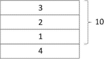
- the laminated film for projecting image display of the present invention has a heat seal layer 4, a transparent support 1, a retardation layer 2 and a selective reflection layer 3 from the bottom in the figure.
- the transparent support 1, the retardation layer 2, and the selective reflection layer 3 constitute the half mirror film 10.
- the laminated film for projecting image display of the present invention has a coefficient of static friction of 1.0 or less on the surface of the heat seal layer 4 opposite to the transparent support 1 (half mirror film 10). As a result, high slipperiness with glass is realized.
- the stacking order of each layer is not limited to the example shown in FIG.
- the heat seal layer 4, the retardation layer 2, the selective reflection layer 3, and the transparent support 1 may be laminated in this order from the lower part in the drawing.
- FIG. 2 conceptually shows a second aspect of the laminated film for displaying a projected image of the present invention.
- the half mirror film 10 is composed of only the selective reflection layer 3.
- the selective reflection layer 3 is a linearly polarized light reflection layer composed of a laminate described later in the laminated film for projecting image display of the present invention
- the half mirror film 10 does not necessarily have the transparent support 1 and the retardation layer 2. You don't have to have it. Therefore, in the example shown in FIG. 2, the selective reflection layer 3 and the heat seal layer 4 laminated on one surface of the selective reflection layer 3 constitute a laminated film for projecting image display.
- FIG. 3 conceptually shows an example of the laminated glass for displaying the projected image of the present invention.
- the “laminated glass for displaying projected images” is also simply referred to as “laminated glass”.
- the laminated glass of the present invention is formed by sandwiching the above-mentioned laminated film for displaying projected images and the interlayer film 5 adjacent to the selective reflection layer of the laminated film for displaying projected images between two glass plates. ..
- the laminated glass shown in FIG. 3 has a first glass plate 6, a heat seal layer 4, a transparent support 1, a retardation layer 2, a selective reflection layer 3, an interlayer film 5, and a second glass plate 7 from the lower part in the drawing. Has.
- the laminated film for displaying projected images of the present invention has good followability to glass by setting the rigidity of the half mirror film at 25 ° C. to 4.0 N ⁇ mm or less, and further, as described above. Since the static friction coefficient of the surface of the heat seal layer opposite to the transparent support is 1.0 or less, the slipperiness of the heat seal layer and the glass is high, and wrinkles of the laminated film for displaying projected images are suppressed. We have realized laminated glass.
- the half mirror film 10 has a transparent support 1 and a retardation layer 2, but the laminated glass of the present invention is not limited thereto. That is, as the laminated glass of the present invention, as the laminated film for displaying the projected image of the present invention, the half mirror film 10 does not have the transparent support 1 and the retardation layer 2, and has the configuration shown in FIG. May be good. Therefore, the laminated glass of the present invention does not necessarily have the transparent support 1 and the retardation layer 2.
- Each layer will be described in more detail.
- the laminated film for displaying a projected image means a half mirror film capable of displaying a projected image with reflected light.
- the laminated film for displaying projected images of the present invention is visible light transmissive.
- the visible light transmittance of the laminated film for displaying a projected image of the present invention is preferably 85% or more, more preferably 86% or more, still more preferably 87% or more.
- the laminated film for displaying a projected image of the present invention does not substantially show reflection in a wavelength region having high visibility.
- a normal laminated glass and a laminated glass incorporating the laminated film for projecting image display of the present invention are compared with respect to light from the normal direction, they are substantially equivalent at a wavelength of about 550 nm. It is preferable that it exhibits various reflections. In particular, it is more preferable to exhibit substantially the same reflection in the visible light wavelength range of 490 to 620 nm.
- “Substantially equivalent reflection” means, for example, the reflectance of natural light (non-polarized light) at a target wavelength measured from a normal direction with a spectrophotometer such as a spectrophotometer “V-670” manufactured by JASCO Corporation. Means that the difference is 10% or less. In the above wavelength range, the difference in reflectance in "substantially equivalent reflection” is preferably 5% or less, more preferably 3% or less, further preferably 2% or less, and particularly preferably 1% or less. Visible light transmission that meets the standard of vehicle windshield glass even when combined with glass with low visible light transmittance to form laminated glass by showing substantially equivalent reflection in the wavelength range with high visibility The rate can be realized.
- the laminated film for projecting image display of the present invention may be a thin film or sheet.
- the laminated film for displaying projected images of the present invention may be in the form of a roll as a thin film before being used for windshield glass (laminated glass) or the like.
- the laminated film for displaying a projected image of the present invention may have a function as a half mirror for at least a part of the projected light, for example, for light in the entire visible light range. It does not need to function as a half mirror. Further, the laminated film for displaying a projected image of the present invention may have the function as the above-mentioned half mirror for light at all incident angles, but the above-mentioned for light at at least a part of the incident angles. It only has to have the function of.
- the laminated film for projecting image display of the present invention includes the half mirror film and the heat seal layer. Moreover, in the laminated film for projecting image display of the present invention, the half mirror film includes a selective reflection layer. Further, the laminated glass of the present invention (laminated glass for displaying projected images) is a laminated glass for displaying projected images and an interlayer film of the present invention sandwiched between two glass plates, and the interlayer film is selective reflection. Adjacent to the layer.
- the laminated film for projection image display of the present invention shown in FIG. 1 has, as an example, a transparent support and a retardation layer in addition to the selective reflection layer. Further, the laminated film for projecting image display of the present invention may include a layer such as an alignment layer and an adhesive layer, if necessary.
- the selective reflection layer is a layer that reflects light wavelength-selectively.
- the selective reflection layer preferably exhibits selective reflection in a part of the visible light wavelength range.
- the selective reflection layer may reflect light for displaying projected images.
- the central wavelength of selective reflection of the selective reflection layer having the central wavelength of selective reflection at the shortest wavelength is preferably 750 nm or less, more preferably 720 nm or less, still more preferably 700 nm or less.
- the half mirror film may include two or more selective reflection layers.
- the central wavelengths of selective reflection of two or more selective reflection layers may be the same or different, but preferably different.
- the central wavelengths of the selective reflections of the two layers are preferably different by 60 nm or more, more preferably 80 nm or more, further preferably 100 nm or more.
- the center wavelength of the selective reflection of the two or more selective reflection layers may be 650 to 780 nm, at least one may be in the range of 650 to 780 nm, and the other one or more may be in the wavelength of more than 780 nm. Both are preferably in the range of 650 to 780 nm.
- the selective reflection layer is preferably a polarization reflection layer.
- the polarization reflection layer is a layer that reflects linearly polarized light, circularly polarized light, or elliptically polarized light.
- the polarization reflection layer is preferably a circular polarization reflection layer or a linear polarization reflection layer.
- the circularly polarized light reflecting layer is a layer that reflects the circularly polarized light of one sense and transmits the circularly polarized light of the other sense in the wavelength range that selectively reflects.
- the linearly polarized light reflecting layer is a layer that reflects linearly polarized light in one polarization direction and transmits linearly polarized light in the polarization direction orthogonal to the reflected polarization direction in a wavelength region that selectively reflects.
- the polarized reflection layer can transmit polarized light that is not reflected, and can also transmit a part of light even in the wavelength range in which the selective reflection layer reflects. Therefore, it is preferable that the tint of the light transmitted through the projection image display half mirror is not easily deteriorated and the visible light transmittance is not easily reduced.
- a cholesteric liquid crystal layer is preferable as the selective reflection layer which is a circularly polarized light reflection layer.
- the cholesteric liquid crystal layer means a layer in which the cholesteric liquid crystal phase is fixed.
- the cholesteric liquid crystal layer may be a layer in which the orientation of the liquid crystal compound in the cholesteric liquid crystal phase is maintained.
- the colletic liquid crystal layer is typically polymerized and cured by ultraviolet irradiation, heating, etc. after the polymerizable liquid crystal compound is placed in the orientation state of the cholesteric liquid crystal phase to form a non-fluid layer, and at the same time, at the same time. Any layer may be used as long as it is changed to a state in which the orientation form does not change due to an external field and an external force.
- the polymerizable liquid crystal compound may have a high molecular weight due to a curing reaction and may lose the liquid crystallinity.
- the cholesteric liquid crystal layer selectively reflects the circularly polarized light of one of the right-handed circularly polarized light and the left-handed circularly polarized light, and exhibits circularly polarized light selective reflection that transmits the circularly polarized light of the other sense.
- a film containing a layer in which a cholesteric liquid crystal phase exhibiting circularly polarized selective reflectivity is fixed many films formed from a composition containing a polymerizable liquid crystal compound have been known conventionally, and the cholesteric liquid crystal layer has been conventionally known. You can refer to the technology.
- the selective reflection center wavelength and the full width at half maximum of the cholesteric liquid crystal layer can be obtained as follows.
- a decrease peak of the transmittance is observed in the selective reflection band.
- the value of the wavelength on the short wavelength side is ⁇ l (nm), and the value of the wavelength on the long wavelength side.
- the center wavelength of the selective reflection obtained as described above substantially coincides with the wavelength at the center of gravity of the reflection peak of the circularly polarized light reflection spectrum measured from the normal direction of the cholesteric liquid crystal layer.
- the head-up display system by using light so that the light is obliquely incident on the windshield glass, it is possible to reduce the reflectance on the surface of the glass plate on the projection light incident side.
- the cholesteric liquid crystal layer For example, light incident in the air having a refractive index of 1 at an angle of 45° to 70° with respect to the normal line of the projected image display portion is incident on the cholesteric liquid crystal layer having a refractive index of about 1.61 at an angle of about 26° to 36°. Transparent with.
- the selective reflection wavelength shifts to the short wavelength side.
- ⁇ d ⁇ ⁇ cos ⁇ 2
- the cholesteric liquid crystal layer having a central wavelength of selective reflection in the range of 650 to 780 nm can reflect projected light in the range of 520 to 695 nm. Since such a wavelength range is a wavelength range with high luminosity factor, the contribution to the brightness of the projected image is high, and as a result, a projected image with high brightness can be realized.
- the pitch of the cholesteric liquid crystal phase depends on the type of chiral agent used together with the polymerizable liquid crystal compound or the concentration of addition thereof, so that a desired pitch can be obtained by adjusting these.
- the method of measuring the sense of the spiral and the pitch the method described in "Introduction to Liquid Crystal Chemistry", edited by the Liquid Crystal Society of Japan, Sigma Publishing 2007, p. be able to.
- each cholesteric liquid crystal layer a cholesteric liquid crystal layer having a spiral sense of either right or left is used.
- the sense of the reflected circularly polarized light of the cholesteric liquid crystal layer matches the sense of the spiral.
- the spiral senses of the cholesteric liquid crystal layers having different central wavelengths of selective reflection may be the same or may contain different ones, but they are preferably the same.
- the half mirror film does not include cholesteric liquid crystal layers having different spiral senses as a cholesteric liquid crystal layer exhibiting selective reflection in the same or overlapping wavelength ranges. This is to prevent the transmittance in a specific wavelength range from dropping to less than 50%, for example.
- ⁇ n can be adjusted by adjusting the type and mixing ratio of the polymerizable liquid crystal compound, or by controlling the temperature at the time of fixing the orientation.
- a plurality of cholesteric liquid crystal layers having the same pitch P and the same spiral sense may be laminated. By stacking cholesteric liquid crystal layers having the same pitch P and the same spiral sense, it is possible to increase the circular polarization selectivity at a specific wavelength.
- a separately prepared cholesteric liquid crystal layer may be laminated using an adhesive or the like, and on the surface of the cholesteric liquid crystal layer formed by the method described below.
- the liquid crystal composition containing the polymerizable liquid crystal compound or the like may be directly applied and the steps of alignment and fixing may be repeated, but the latter is preferred.
- the orientation direction of the liquid crystal molecules on the air interface side of the previously formed cholesteric liquid crystal layer and the cholesteric liquid crystal layer formed thereon This is because the alignment orientations of the liquid crystal molecules on the lower side of the cholesteric liquid crystal molecules are aligned with each other, and the polarization characteristics of the laminated body of the cholesteric liquid crystal layer are improved. Further, there is an effect that the distortion of the cholesteric liquid crystal layer which may be caused by the thickness unevenness of the adhesive layer and the interference unevenness do not occur.
- the thickness of the cholesteric liquid crystal layer is not limited, it is preferably 0.5 to 10 ⁇ m, more preferably 1.0 to 8.0 ⁇ m, still more preferably 1.5 to 6.0 ⁇ m.
- the visible light transmittance can be maintained high by setting the thickness of the cholesteric liquid crystal layer in the above range.
- cholesteric liquid crystal layer a material and a method for manufacturing the cholesteric liquid crystal layer will be described.
- the material used for forming the cholesteric liquid crystal layer described above include a liquid crystal composition containing a polymerizable liquid crystal compound and a chiral agent (optically active compound). If necessary, the above-mentioned liquid crystal composition further mixed with a surfactant and a polymerization initiator and dissolved in a solvent or the like is applied to a support, an alignment layer, a cholesteric liquid crystal layer as an lower layer, or the like, and after cholesteric orientation aging, A cholesteric liquid crystal layer can be formed by fixing the liquid crystal composition by curing.
- the polymerizable liquid crystal compound may be a rod-shaped liquid crystal compound or a disk-shaped liquid crystal compound, but is preferably a rod-shaped liquid crystal compound.
- Examples of the rod-shaped polymerizable liquid crystal compound forming the cholesteric liquid crystal layer include a rod-shaped nematic liquid crystal compound.
- rod-shaped nematic liquid crystal compounds examples include azomethines, azoxys, cyanobiphenyls, cyanophenyl esters, benzoic acid esters, cyclohexanecarboxylic acid phenyl esters, cyanophenylcyclohexanes, cyano-substituted phenylpyrimidins, and alkoxy-substituted phenylpyrimidins.
- Phenyldioxans, trans, and alkenylcyclohexylbenzonitriles are preferably used. Not only a low molecular weight liquid crystal compound but also a high molecular weight liquid crystal compound can be used.
- the polymerizable liquid crystal compound is obtained by introducing a polymerizable group into the liquid crystal compound.
- the polymerizable group include an unsaturated polymerizable group, an epoxy group, and an aziridinyl group, and an unsaturated polymerizable group is preferable, and an ethylenically unsaturated polymerizable group is particularly preferable.
- the polymerizable group can be introduced into the molecule of the liquid crystal compound by various methods.
- the number of polymerizable groups contained in the polymerizable liquid crystal compound is preferably 1 to 6 in one molecule, and more preferably 1 to 3.
- Examples of polymerizable liquid crystal compounds include Makromol. Chem. , 190, 2255 (1989), Advanced Materials, 5 (107) (1993), U.S.
- the amount of the polymerizable liquid crystal compound added to the liquid crystal composition is preferably 80 to 99.9% by mass, preferably 85 to 99% by mass, based on the solid content mass (mass excluding the solvent) of the liquid crystal composition. It is more preferably 5.5% by mass, and particularly preferably 90 to 99% by mass.
- the chiral agent has a function of inducing a helical structure of a cholesteric liquid crystal phase.
- the chiral agent has different helical sense or helical pitch induced by the compound, and therefore may be selected according to the purpose.
- the chiral agent is not particularly limited, and known compounds can be used. Examples of chiral agents include Liquid Crystal Device Handbook (Chapter 3, 4-3, TN, Chiral Auxiliary for STN, page 199, Japan Society for the Promotion of Science 142, 1989), Japanese Patent Application Laid-Open No. 2003-287623, Japan. Examples thereof include compounds described in JP-A-2002-302487, JP-A-2002-80478, JP-A-2002-80851, JP-A-2010-181852, and JP-A-2014-034581.
- the chiral agent generally contains an asymmetric carbon atom, but an axially asymmetric compound or a planar asymmetric compound containing no asymmetric carbon atom can also be used as the chiral agent.
- axially asymmetric or surface asymmetric compounds include binaphthyl, helicene, paracyclophane, and derivatives thereof.
- the chiral agent may have a polymerizable group. When both the chiral agent and the liquid crystal compound have a polymerizable group, a repeating unit derived from the polymerizable liquid crystal compound and a chiral agent are generated by a polymerization reaction between the polymerizable chiral agent and the polymerizable liquid crystal compound. Polymers having repeating units can be formed.
- the polymerizable group contained in the polymerizable chiral agent is preferably the same type of group as the polymerizable group contained in the polymerizable liquid crystal compound. Therefore, the polymerizable group of the chiral agent is preferably an unsaturated polymerizable group, an epoxy group or an aziridinyl group, more preferably an unsaturated polymerizable group, and preferably an ethylenically unsaturated polymerizable group. More preferred. Moreover, the chiral agent may be a liquid crystal compound.
- the chiral agent examples include isosorbide derivatives, isomannide derivatives, and binaphthyl derivatives.
- isosorbide derivative a commercially available product such as LC-756 manufactured by BASF may be used.
- the content of the chiral agent in the liquid crystal composition is preferably 0.01 to 200 mol% of the amount of the polymerizable liquid crystal compound, and more preferably 1 to 30 mol %.
- the content of the chiral agent in the liquid crystal composition means the concentration (mass %) of the chiral agent with respect to the total solid content in the composition.
- the liquid crystal composition preferably contains a polymerization initiator.
- the polymerization initiator used is preferably a photopolymerization initiator capable of initiating the polymerization reaction by irradiation with ultraviolet rays.
- the photopolymerization initiator include ⁇ -carbonyl compounds (described in US Pat. Nos. 2,367,661 and 2,367,670), acyloin ethers (US Pat. No. 2,448,828), and ⁇ -hydrocarbon-substituted fragrances.
- Group acyloin compounds described in U.S. Pat. No.
- JP-A-2014-137466 JP-A-4223071, JP-A-2010-262028, JP-T-2014-500852-
- oxime compounds JP-A-2000-66385, JP-A-444567
- oxadiazole compounds described in US Pat. No. 4,212,970
- an acylphosphine oxide compound or an oxime compound is also preferable to use as the polymerization initiator.
- the acylphosphine oxide compound for example, a commercially available IRGACURE810 (compound name: bis (2,4,6-trimethylbenzoyl) -phenylphosphine oxide) manufactured by BASF Japan Ltd. can be used.
- Examples of the oxime compound include IRGACURE OXE01 (manufactured by BASF), IRGACURE OXE02 (manufactured by BASF), TR-PBG-304 (manufactured by Joshu Powerful Electronics New Materials Co., Ltd.), ADEKA ARCULS NCI-831, and ADEKA ARCULS NCI-930.
- Commercially available products such as (manufactured by ADEKA) and ADEKA Arkuru's NCI-831 (manufactured by ADEKA) can be used.
- the polymerization initiator may be used alone or in combination of two or more.
- the content of the photopolymerization initiator in the liquid crystal composition is preferably 0.1 to 20% by mass, more preferably 0.5 to 5% by mass, based on the content of the polymerizable liquid crystal compound.
- the liquid crystal composition may optionally contain a crosslinking agent in order to improve the film strength after curing and the durability.
- a crosslinking agent those that are cured by ultraviolet rays, heat, humidity and the like can be preferably used.
- the cross-linking agent is not particularly limited and may be appropriately selected depending on the intended purpose. Examples thereof include polyfunctional acrylate compounds such as trimethylolpropane tri(meth)acrylate and pentaerythritol tri(meth)acrylate; glycidyl (meth)acrylate.
- Epoxy compounds such as ethylene glycol diglycidyl ether; 2,2-bishydroxymethylbutanol-tris[3-(1-aziridinyl)propionate], aziridine compounds such as 4,4-bis(ethyleneiminocarbonylamino)diphenylmethane; hexa Isocyanate compounds such as methylene diisocyanate and biuret type isocyanate; polyoxazoline compounds having an oxazoline group in the side chain; alkoxysilane compounds such as vinyltrimethoxysilane and N-(2-aminoethyl)3-aminopropyltrimethoxysilane.
- a known catalyst can be used depending on the reactivity of the cross-linking agent, and the productivity can be improved in addition to the improvement of the film strength and durability. These may be used alone or in combination of two or more.
- the content of the cross-linking agent is preferably 3 to 20% by mass, more preferably 5 to 15% by mass, based on the content of the polymerizable liquid crystal compound. By setting the content of the cross-linking agent to 3% by mass or more, the effect of improving the cross-linking density can be obtained. By setting the content of the cross-linking agent to 20% by mass or less, it is possible to prevent a decrease in the stability of the cholesteric liquid crystal layer.
- orientation control agent An orientation control agent may be added to the liquid crystal composition that contributes to the stable or rapid planar orientation of the cholesteric liquid crystal layer.
- the orientation control agent include fluorine (meth) acrylate-based polymers described in paragraphs [0018] to [0043] of JP-A-2007-272185, and paragraphs [0031]-[0034] of JP-A-2012-203237. ] And the like, and the compounds represented by the formulas (I) to (IV), and the compounds described in JP-A-2013-113913.
- the orientation control agent one type may be used alone, or two or more types may be used in combination.
- the amount of the orientation control agent added to the liquid crystal composition is preferably 0.01 to 10% by mass, more preferably 0.01 to 5% by mass, and 0.02 to 1 to the total mass of the polymerizable liquid crystal compound. Mass% is particularly preferred.
- the liquid crystal composition may contain at least one selected from various additives such as a surfactant for adjusting the surface tension of the coating film and making the thickness uniform, and a polymerizable monomer. Further, if necessary, a polymerization inhibitor, an antioxidant, an ultraviolet absorber, a light stabilizer, a coloring material, metal oxide fine particles, etc. are added to the liquid crystal composition as long as the optical performance is not deteriorated. can do.
- a liquid crystal composition in which a polymerizable liquid crystal compound, a polymerization initiator, a chiral agent added as necessary, a surfactant, etc. are dissolved in a solvent is prepared as a support, an orientation layer, or first.
- the cholesteric liquid crystal layer is coated on the cholesteric liquid crystal layer or the like and dried to obtain a coating film, and the coating film is irradiated with active light to polymerize the cholesteric liquid crystal composition to obtain a cholesteric liquid crystal layer having fixed cholesteric regularity.
- the laminated film composed of a plurality of cholesteric liquid crystal layers can be formed by repeating the above-mentioned manufacturing process of the cholesteric liquid crystal layer.
- the solvent used for preparing the liquid crystal composition is not particularly limited and may be appropriately selected depending on the purpose, but organic solvents are preferably used.
- the organic solvent is not particularly limited and may be appropriately selected depending on the intended purpose. For example, ketones, alkyl halides, amides, sulfoxides, heterocyclic compounds, hydrocarbons, esters, and ethers. And so on. These may be used alone or in combination of two or more. Among these, ketones are particularly preferable in consideration of the load on the environment.
- the method for applying the liquid crystal composition is not particularly limited and may be appropriately selected depending on the intended purpose.
- Examples include a die coating method, a spin coating method, a dip coating method, a spray coating method, and a slide coating method.
- It can also be carried out by transferring a liquid crystal composition separately coated on a support.
- the heating temperature is preferably 200 ° C. or lower, more preferably 130 ° C. or lower.
- an optical thin film in which the polymerizable liquid crystal compound is twisted and aligned so as to have a spiral axis in a direction substantially perpendicular to the film surface is obtained.
- the liquid crystal composition can be cured by further polymerizing the aligned liquid crystal compound.
- the polymerization may be either thermal polymerization or photopolymerization utilizing light irradiation, but photopolymerization is preferred. It is preferable to use ultraviolet light for the light irradiation.
- the irradiation energy is preferably 20mJ / cm 2 ⁇ 50J / cm 2, more preferably 100 ⁇ 1,500mJ / cm 2.
- light irradiation may be carried out under heating and/or under a nitrogen atmosphere.
- the irradiation ultraviolet wavelength is preferably 350 to 430 nm.
- the polymerization reaction rate is preferably high, preferably 70% or more, more preferably 80% or more.
- the polymerization reaction rate can be determined by measuring the consumption rate of the polymerizable functional group using an IR absorption spectrum.
- a linearly polarized light reflective layer may be used as the selective reflective layer of the half mirror film.
- the linearly polarized light reflection layer include a polarizer in which thin films having different refractive index anisotropies are laminated. Similar to the cholesteric liquid crystal layer, such a polarizer can have a high visible light transmittance and exhibit a central wavelength of selective reflection in a specific wavelength range.
- a polarizer can have a high visible light transmittance and exhibit a central wavelength of selective reflection in a specific wavelength range.
- projected light that is obliquely incident can be reflected at a wavelength having high visibility.
- a wide variety of materials can be used to form polarizers when processed under the conditions selected to obtain the desired refractive index relationship.
- one of the first materials has a different index of refraction than the second material in the chosen direction.
- This difference in refractive index can be achieved in a variety of ways, including stretching, extrusion, or coating during or after film formation.
- the two materials have similar rheological properties (eg melt viscosity) so that they can be coextruded.
- a commercially available product can be used as the polarizer in which thin films having different refractive index anisotropy are laminated.
- a product in which a reflective polarizing plate and a temporary support are laminated may be used.
- Examples of commercially available products include DBEF (manufactured by 3M Company), APF (Advanced Polarizing Film (manufactured by 3M Company)), and the like.
- the thickness of the reflective polarizing plate is preferably 0.5 to 50 ⁇ m, more preferably 1.0 to 30 ⁇ m.
- the half mirror film may include a retardation layer in addition to the selective reflection layer.
- the half mirror film preferably contains a retardation layer.
- the retardation layer is provided so as to be on the visual side with respect to all the selective reflection layers (cholesteric liquid crystal layers) at the time of use. Even when the half-mirror film of the projection image display laminated film includes a cholesteric liquid crystal layer as a selective reflection layer, for example, a projector of a head-up display system (image display system) emits a circularly polarized projection image. In that case, the half mirror film may not include the retardation layer.
- the retardation layer is not particularly limited and can be appropriately selected according to the purpose.
- the retardation layer include a stretched polycarbonate film, a stretched norbornene-based polymer film, a transparent film oriented by containing inorganic particles having birefringence such as strontium carbonate, and an inorganic dielectric on a support.
- examples thereof include a thin film obtained by obliquely depositing a polycarbonate compound, a film in which a liquid crystal compound is uniaxially oriented and fixed in orientation, and a film in which a polymerizable liquid crystal compound is uniaxially oriented and fixed in orientation.
- the retardation layer is preferably a film in which a polymerizable liquid crystal compound is uniaxially oriented and oriented and fixed.
- a liquid crystal composition containing a polymerizable liquid crystal compound is applied to the surface of a temporary support or an alignment layer, and the polymerizable liquid crystal compound in the liquid crystal composition is formed in a nematic orientation in a liquid crystal state and then cured. Can be fixed and formed by.
- the retardation layer can be formed in the same manner as the cholesteric liquid crystal layer described above, except that a chiral agent is not added to the liquid crystal composition.
- the heating temperature is preferably 50 to 120 ° C, more preferably 60 to 100 ° C.
- the retardation layer is a layer obtained by applying a composition containing a polymer liquid crystal compound to the surface of a temporary support, an orientation layer, or the like, forming a nematic orientation in a liquid crystal state, and then cooling to fix the orientation. May be
- the thickness of the retardation layer is preferably 0.2 to 300 ⁇ m, more preferably 0.4 to 150 ⁇ m, and even more preferably 0.5 to 80 ⁇ m.
- the thickness of the retardation layer formed from the liquid crystal composition is not particularly limited, but is preferably 0.2 to 10 ⁇ m, more preferably 0.4 to 5.0 ⁇ m, and even more preferably 0.5 to 2.0 ⁇ m.
- the direction of the slow axis of the retardation layer depends on the incident direction of incident light for displaying a projected image and the sense of the spiral of the cholesteric liquid crystal layer when used as an image display system, for example, a head-up display system. It is preferable to determine.
- the direction of the slow axis of the retardation layer can be determined if the direction when used as a head-up display is determined.
- the in-plane retardation in the case where the incident light is below (vertically below) the laminated glass (laminated film for projecting image display) and is incident on the cholesteric liquid crystal layer from the retardation layer side, the in-plane retardation According to the above, the direction of the slow axis can be determined within the following range.
- the slow axis of the retardation layer is +30° to +85 with respect to the vertical direction of the laminated glass (laminated film for projecting image display). It is preferably in the range of ° or -30° to -85°.
- the slow axis of the retardation layer is +120° to +175° or ⁇ 120° to ⁇ 175 with respect to the vertical direction of the laminated glass.
- the ° range is preferred.
- windshield glass (combiner) installed in vehicles such as automobiles, it is the direction within the plane of the windshield glass (combiner) during normal use, and it is vertical (vertical vertical direction) with respect to the driver.
- the direction of the vehicle and the surface on the visual side observation side, driver side, inside the vehicle
- the windshield glass, the laminated glass, and the laminated film for projecting image display when referred to as a vertically upward direction, can be specified as described above, the windshield glass, the laminated glass, and the laminated film for projecting image display.
- On the visible side surface of the film it means a direction along the vertical direction during use, which can be specified as described above.
- the slow axis of the retardation layer is +35° to +70° or ⁇ 35° to ⁇ 70 with respect to the vertical direction of the laminated glass.
- the ° range is more preferred.
- the slow axis of the retardation layer is +125° to +160° or ⁇ 125° to ⁇ 160 with respect to the vertical direction of the laminated glass. The ° range is more preferred.
- the slow-phase axis + and-are defined above, which means the clockwise direction (+) and the counterclockwise direction (-) when the viewing position is fixed.
- the preferred direction depends on the sense of spiral of the cholesteric liquid crystal layer contained in the half mirror film of the laminated film for displaying the projected image. That is, the slow axis of the retardation layer is set so that the incident linearly polarized light (p-polarized light) is circularly polarized light in the turning direction reflected by the cholesteric liquid crystal layer according to the circularly polarized light reflected by the cholesteric liquid crystal layer. To do.
- the direction of the slow axis of the retardation layer is vertically upward when viewed from the retardation layer side with respect to the cholesteric liquid crystal layer.
- it may be 30 ° to 85 ° or 120 ° to 175 ° clockwise.
- the slow axis direction of the retardation layer is 30 ° to counterclockwise when viewed from the retardation layer side with respect to the cholesteric liquid crystal layer. It may be 85 ° or 120 ° to 175 °.
- the half mirror film of the laminated film for projecting image display of the present invention may include a second retardation layer in addition to the above retardation layer.
- the above-mentioned retardation layer hereinafter, also referred to as “first retardation layer”
- all cholesteric liquid crystal layers and the second retardation layer are arranged in this order.
- first retardation layer the above-mentioned retardation layer
- all cholesteric liquid crystal layers and the second retardation layer
- the second retardation layer are arranged in this order.
- the first retardation layer, the selective reflection layer, and the second retardation layer may be provided in this order from the viewing side.
- the double image it is possible to further prevent a double image when a projected image is formed by incident p-polarized light.
- the reason why the double image can be further prevented by using the second retardation layer is that the light having a wavelength not in the selective reflection band of the cholesteric liquid crystal layer is polarized by the cholesteric liquid crystal layer and reflected on the back surface of the windshield glass. It is presumed that this is because it is possible to prevent double images based on the fact that the image is doubled.
- the in-plane retardation of the second retardation layer may be appropriately adjusted within a range of 160 to 460 nm, preferably 240 to 420 nm at a wavelength of 550 nm.
- the material and thickness of the second retardation layer can be selected in the same range as that of the first retardation layer.
- the slow axis direction of the second retardation layer is preferably determined according to the incident direction of the incident light for displaying the projected image and the sense of the spiral of the cholesteric liquid crystal layer.
- the slow axis is +10° with respect to the vertical direction of the laminated glass (laminated film for projecting image display). It is preferable to be in the range of to +35°, or ⁇ 10° to ⁇ 35°.
- the slow axis is +100° to +140°, or ⁇ 100° to ⁇ with respect to the vertical direction of the laminated glass. It is preferable that the range is 140 °.
- the half mirror film constituting the laminated film for projecting image display of the present invention is not limited to the above-mentioned first and second retardation layers which are provided as necessary and the selective reflection layer which is an essential component. , Other layers may be included. All the other layers are preferably transparent in the visible light region. Further, it is preferable that all the other layers have low birefringence. In the present specification, having low birefringence means that the in-plane retardation is 10 nm or less in the wavelength range in which the half mirror for projection image display of the windshield glass used in the present invention reflects. The in-plane retardation is preferably 5 nm or less.
- all the other layers have a small difference in refractive index from the average refractive index (in-plane average refractive index) of the cholesteric liquid crystal layer.
- other layers include a support (transparent support), an alignment layer, and an adhesive layer.
- the half mirror film may include a transparent support.
- the retardation layer may also serve as a transparent support.
- the transparent support may also serve as a retardation layer.
- the transparent support preferably used in the present invention has an absolute value of in-plane retardation of 10 nm or less at a wavelength of 550 nm, preferably 5 nm or less.
- the absolute value of the phase difference Rth in the thickness direction is preferably 40 nm or less, more preferably 30 nm or less. Since the phase difference is small, the polarization disturbance due to the transparent support is small.
- the transparent support may shrink due to heat.
- the transparent support when the half mirror film is sandwiched between two curved glasses to form a laminated glass, it is preferable in that the transparent support is heat-shrinked, the half mirror film shrinks, and wrinkles can be suppressed. It is estimated that when a flat half mirror film is sandwiched between curved glass, wrinkles caused by an extra film can be eliminated by shrinking the half mirror film including the transparent support.
- the transparent support includes a process of stretching in manufacturing, and the stress due to stretching exists as a residual stress. Therefore, this residual stress can be utilized to cause heat shrinkage by heating the autoclave during the production of laminated glass. It is presumed that this heat shrinkage can eliminate the wrinkles generated by pinching with curved glass.
- the half mirror film using the transparent support that is heat-shrinkable has an effect of effectively suppressing the generation of wrinkles in a portion where the glass has a large curvature.
- the film In the part where the glass has a large curvature, the film has a degree of freedom to expand in the thickness direction, and the film shrinks in the surface direction. A mechanism of action in which film shrinkage hardly occurs can be considered.
- the temperature at which the transparent support heat shrinks varies depending on the material for forming the transparent support, but it is preferably shrunk in the range of 80 to 200 ° C., which is the autoclave treatment temperature in the production of general laminated glass. It is more preferable to shrink in the range of 100 to 160 ° C.
- the heating for shrinking the transparent support may be performed on the entire laminated glass, or may be locally performed on a portion having a high curvature and prone to wrinkles.
- the amount of shrinkage of the transparent support required to suppress wrinkles of the half mirror film differs depending on the curvature and size of the glass.
- the transparent support has a heat shrinkage of 0.01 to 5.0% in the direction in which the heat shrinkage is maximum and in the direction orthogonal to the direction under the heating conditions of the autoclave in the production of laminated glass. Is preferable, 0.05 to 3.0% is more preferable, and 0.2 to 2.0% is further preferable.
- the heat shrinkage is 0.01% or more, wrinkles are less likely to occur during the production of laminated glass. Further, when the heat shrinkage is 5.0% or less, foaming is less likely to occur during the production of laminated glass.
- the heat shrinkage rate can be appropriately adjusted depending on the stretching conditions when manufacturing the transparent support.
- the transparent support is preferably made of cellulose acylate and a resin such as acrylic.
- the transparent support is preferably made of a cellulose acylate resin, and more preferably made of a triacetyl cellulose resin or a diacetyl cellulose resin.
- the two glass plates, the half mirror film, and the interlayer film described later are formed while heating the transparent support so that the storage elastic modulus of the half mirror film (laminated body) is 2.0 GPa or less. It is preferable that they are closely attached. It is preferable that the storage elastic modulus is 2.0 GPa or less to improve the followability to the curved glass.
- the thickness of the transparent support may be about 5.0 to 200 ⁇ m, preferably 10 to 100 ⁇ m, more preferably 15 to 80 ⁇ m, and even more preferably 20 to 40 ⁇ m.
- the temporary support When a half mirror film having a cholesteric liquid crystal layer or the like is produced using the temporary support, the temporary support may be finally peeled off. That is, the support exists only at the time of producing the half mirror film, and may not be a layer constituting the half mirror film when the half mirror film is completed. In this case, the support need not be transparent.
- the half mirror film may include an alignment layer as a lower layer on which the liquid crystal composition is applied when forming the cholesteric liquid crystal layer or the retardation layer.
- the alignment layer has a rubbing treatment of organic compounds such as polymers (polyimide, polyvinyl alcohol, polyester, polyarylate, polyamideimide, polyetherimide, resins such as polyamide and modified polyamide), oblique deposition of inorganic compounds, and microgrooves. It can be provided by means such as layer formation and accumulation of organic compounds (eg, ⁇ -tricosanoic acid, dioctadecylmethylammonium chloride and methyl stearylate) using the Langmuir-Brojet method (LB membrane).
- organic compounds eg, ⁇ -tricosanoic acid, dioctadecylmethylammonium chloride and methyl stearylate
- an alignment layer which has an alignment function by applying an electric field, a magnetic field, or light irradiation may be used.
- the alignment layer made of a polymer is subjected to a rubbing treatment, and then the liquid crystal composition is applied to the rubbing treated surface.
- the rubbing treatment can be carried out by rubbing the surface of the polymer layer with paper or cloth in a certain direction.
- the liquid crystal composition may be applied to the surface of the transparent support that has been rubbed without providing an alignment layer. That is, the transparent support may act as an alignment layer.
- the thickness of the alignment layer is not limited, but is preferably 0.01 to 5.0 ⁇ m, more preferably 0.05 to 2.0 ⁇ m.
- the alignment layer may be peeled off together with the temporary support. That is, the alignment film exists only when the half mirror film is produced, and may not be a layer that constitutes the half mirror film when the half mirror film is completed.
- the half mirror film may have an adhesive layer for improving the adhesiveness of each layer, if necessary.
- the position where the adhesive layer is provided is, for example, between the cholesteric liquid crystal layer when the selective reflection layer is composed of a plurality of cholesteric layers, between the selective reflection layer and the retardation layer, and between the selective reflection layer and the transparent support. Is exemplified. Further, the adhesive layer may be provided on the surface of the selective reflection layer. Thereby, the adhesion with the adjacent interlayer film can be improved.
- the adhesive layer may be formed of an adhesive.
- adhesives include hot-melt type, thermosetting type, photo-curing type, reaction-curing type, and pressure-sensitive adhesive type that does not require curing. These adhesives are, as materials, acrylate-based, urethane-based, urethane acrylate-based, epoxy-based, epoxy acrylate-based, polyolefin-based, modified olefin-based, polypropylene-based, ethylene vinyl alcohol-based, vinyl chloride-based, chloroprene rubber-based, Compounds such as cyanoacrylate-based, polyamide-based, polyimide-based, polystyrene-based, and polyvinyl butyral-based compounds can be used.
- the photocuring type is preferable as the curing method.
- the material is preferably an acrylate-based material, a urethane acrylate-based material, an epoxy acrylate-based material, or the like.
- the adhesive layer may be formed by using a highly transparent adhesive transfer tape (OCA tape).
- OCA tape a highly transparent adhesive transfer tape
- a commercially available product for an image display device particularly a commercially available product for the surface of an image display portion of an image display device may be used.
- Examples of commercially available products include an adhesive sheet manufactured by Panac (PD-S1 and the like), an adhesive sheet of the MHM series manufactured by Niei Kako, and the like.
- the thickness of the adhesive layer is preferably 0.5 to 10 ⁇ m, more preferably 1.0 to 5.0 ⁇ m.
- the thickness of the adhesive layer formed by using the OCA tape may be 10 ⁇ m to 50 ⁇ m, preferably 15 ⁇ m to 30 ⁇ m. It is preferable that the half mirror for displaying the projected image has a uniform thickness in order to reduce color unevenness and the like.
- ⁇ indicates the elastic modulus [MPa]
- d indicates the film thickness [ ⁇ m].
- the half mirror film has a rigidity at 25° C. of 4.0 N ⁇ mm or less. Therefore, the elastic modulus of the half mirror film in this formula is the elastic modulus when the half mirror film is at 25°C.
- rigidity means the rigidity at 25° C. unless otherwise specified. If the rigidity of the half mirror film exceeds 4.0 N ⁇ mm, it will not be able to follow the curved glass when it is made of laminated glass, which will be described later, and there will be inconveniences such as wrinkles, bending, and breakage.
- the lower limit of the rigidity of the half mirror film is not limited, but if the rigidity is too low, the half mirror film may be easily broken and the half mirror film itself may be difficult to handle. Considering this point, the strength of the half mirror film is preferably 0.01 N ⁇ mm or more.
- the rigidity of the half mirror film is preferably 0.015 to 2.0 N ⁇ mm, more preferably 0.02 to 1.0 N ⁇ mm. The rigidity of the half mirror film will be described in detail later.
- the laminated film for displaying projected images of the present invention has a heat seal layer in addition to the half mirror film.
- the heat seal layer 4 is provided on the surface of the transparent support 1 opposite to the selective reflection layer 3 (retardation layer 2).
- the "heat seal layer” is a half mirror film of the laminated film for displaying projected images when a laminated glass is produced using the laminated film for displaying projected images of the present invention.
- it is a layer for physically joining the transparent support 1) and the glass plate.
- the thermoplastic resin contained in the heat-sealing layer has an action of being fused by heating during the production of laminated glass.
- the half mirror film and the glass plate can be strongly adhered to each other while suppressing the occurrence of wrinkles during the production of laminated glass.
- a mixed layer in which the components of the transparent support and the components of the heat seal layer are mixed is formed between the transparent support and the heat seal layer.
- the adhesion between the transparent support and the heat seal layer is also strengthened, and when laminated glass is used, peeling failure inside the laminated glass is prevented.
- the heat seal layer and the selective reflection layer may be in direct contact with each other, or may be indirectly in contact with each other with an adhesive layer or the like interposed between them.
- the thickness of the heat seal layer is 40 ⁇ m or less.
- the lower limit of the thickness of the heat seal layer is not limited, but is preferably 0.1 ⁇ m or more. It is preferable that the thickness of the heat seal layer is 0.1 ⁇ m or more because sufficient adhesion between the half mirror film and the glass can be obtained.
- the thickness of the heat seal layer may be 40 ⁇ m or less, but is preferably 0.1 to 10.0 ⁇ m, more preferably 0.1 to 5.0 ⁇ m, further preferably 0.1 to 2.5 ⁇ m, and 0.1. It is particularly preferable that the thickness is up to 1.0 ⁇ m.
- the heat seal layer contains a thermoplastic resin.
- the heat seal layer is preferably transparent.
- the thermoplastic resin is preferably an amorphous resin.
- a thermoplastic resin one having good affinity and adhesiveness with a glass plate is preferable, and a polyvinyl acetal resin typified by polyvinyl butyral (PVB) resin, an ethylene-vinyl acetate copolymer, and a chlorine-containing resin.
- PVB polyvinyl butyral
- a resin selected from the group consisting of resins can be used.
- the main component of the heat seal layer is preferably the resin described above.
- the main component is a component that accounts for 50% by mass or more of the total mass of the heat seal layer.
- a polyvinyl acetal resin typified by a polyvinyl butyral resin and an ethylene-vinyl acetate copolymer are preferably exemplified, and a polyvinyl acetal resin typified by a polyvinyl butyral resin (also referred to as an alkyl acetalized polyvinyl alcohol) is more preferable.
- the resin is preferably a synthetic resin.
- Polyvinyl butyral can be obtained by acetalizing polyvinyl alcohol with butyraldehyde.
- a preferable lower limit of the degree of acetalization of the polyvinyl acetal resin typified by the above-mentioned polyvinyl butyral resin is 40%, a preferable upper limit thereof is 85%, a more preferable lower limit thereof is 60%, and a more preferable upper limit thereof is 80%.
- the polyvinyl alcohol used as a raw material for these resins is usually obtained by saponifying polyvinyl acetate, and polyvinyl alcohol having a saponification degree of 80 to 99.8 mol% is generally used.
- the preferable lower limit of the degree of polymerization of polyvinyl alcohol is 200, and the preferable upper limit thereof is 10,000.
- a more preferable lower limit is 500 and a more preferable upper limit is 5000.
- the degree of polymerization referred to here represents the average degree of polymerization.
- the polyvinyl acetal resin preferably used for the heat seal layer examples include KS-10, KS-1, KS-3, KS-5, and BL-5 manufactured by Sekisui Chemical Co., Ltd. These polyvinyl acetal resins tend to form a mixed layer with the transparent support when applied to the transparent support. Further, in order to apply a thin layer of the heat seal layer, it is important that the coating liquid has a low viscosity. From this point of view, the calculated molecular weight of the polyvinyl acetal resin is preferably 10,000 or more and 50,000 or less, and KS-10 and KS-1 are preferable. In the present invention, the calculated molecular weight is defined as a value obtained by multiplying the average degree of polymerization of polyvinyl alcohol as a raw material by the molecular weight of the acetalized unit.
- the heat seal layer contains, in addition to the polyvinyl acetal resin, a cross-linking agent that cross-links the polyvinyl alcohol unit in the polyvinyl acetal resin structure.
- a cross-linking agent include epoxy-based additives, and a compound having two or more epoxy groups in one molecule is preferable, and a compound represented by the following general formula (EP1) is preferable.
- EP1 Ep-CH 2 -O- (R- O) n -CH 2 -Ep (EP1)
- Ep is an epoxy group
- R is an alkylene group having 2 to 4 carbon atoms
- n is 1 to 30.
- the plurality of Rs may be the same or different.
- Specific examples of the compound represented by the above general formula (EP1) include Denacol EX-810, 811, 821, 830, 832, 841, 850, 851, 861, 911, 920, 931, and Nagase ChemteX Corporation. , 941 and the like.
- a cationic polymerization initiator which is an onium salt composed of a light-absorbing cation portion and an anion portion which is an acid generation source
- a sulfonium salt-based or iodonium salt-based cationic polymerization initiator can be used.
- an iodonium-based cationic polymerization initiator is preferable.
- the heat seal layer is preferably prepared using a coating composition.
- the coating composition forming the heat seal layer may contain at least one solvent.
- the solvent include ketones; acetone, methyl ethyl ketone, cyclohexanone, methyl isobutyl ketone, and diacetone alcohol, and esters when the transparent support is triacetyl cellulose; methyl formate, methyl acetate, ethyl acetate, Nitrogen-containing compounds such as butyl acetate and ethyl lactate; nitromethane, acetonitrile, N-methylpyrrolidone and N,N-dimethylformamide, glycols; methyl glycol, methyl glycol acetate, etc., ethers; tetrahydrofuran, 1,4-dioxane, dioxolane, diisopropyl ether, etc., halogenated hydrocarbons;
- alcohols such as methanol, ethanol, isopropyl alcohol, butanol and isobutyl alcohol, and aromatic hydrocarbons such as toluene and xylene can also be used as a mixture with the above-mentioned solvent.
- the solvent of the coating composition of the heat seal layer is preferably a solvent that dissolves the thermoplastic resin contained in the heat seal layer, and in the case of polyvinyl butyral, alcohols; methanol, ethanol, isopropyl alcohol, butanol, isobutyl alcohol, and Aromatic hydrocarbons such as diacetone alcohol; toluene and glycol ethers such as xylene; methyl cellosolve, ethyl cellosolve, butyl cellosolve, and cellosolve acetate and other ketones; acetone, methyl ethyl ketone, cyclohexanone, methyl isobutyl ketone, diisobutyl Amides such as ketones and isophorone; N,N-dimethylacetamide, N,N-dimethylformamide, N-methyl-2-pyrrolidone and the like, esters; methyl formate, methyl acetate, ethyl acetate, buty
- the coefficient of static friction of the heat seal layer is 1.0 or less.
- the static friction coefficient of the heat seal layer is the static friction coefficient of the surface of the heat seal layer opposite to the half mirror.
- the coefficient of static friction of the heat-sealing layer exceeds 1.0, the slipperiness of the laminated glass with the glass plate is insufficient, which causes bending and wrinkling during the production of the laminated glass, which is caused by stretching wrinkles. As a result, the laminated film for displaying the projected image is broken and becomes a mark.
- the coefficient of static friction of the heat seal layer is the coefficient of static friction with respect to the float glass.
- Preferable means for lowering the coefficient of static friction of the heat seal layer include a method of forming surface irregularities by embossing and using particles, and a method of unevenly distributing a compound that lowers the coefficient of friction with glass on the surface.
- the method using fine particles is considered to be preferable because it can form fine irregularities to reduce static friction, does not affect the optical performance, and does not increase the number of steps.
- the fine particles include silica (silicon dioxide), aluminum oxide, titanium dioxide, zirconium oxide, calcium carbonate, talc, clay, calcined kaolin, calcined calcium silicate, hydrated calcium silicate, aluminum silicate, magnesium silicate and calcium phosphate.
- Inorganic fine particles and fine particles containing at least one of polymer fine particles and the like may be added to the heat seal layer in an appropriate amount. At this time, it is considered that the added fine particles are distributed on the surface of the heat seal layer, so that the surface is roughened and the coefficient of static friction is lowered.
- the fine particles to be added to the heat seal layer are preferably dispersed particles having an average primary particle size of 5 to 380 nm, and more preferably dispersed particles having an average primary particle size of 30 to 200 nm. Further, as the fine particles added to the heat seal layer, fine particles forming secondary particles which are aggregates of primary particles can also be preferably used. At this time, the average primary particle diameter of the primary particles is preferably 5 to 50 nm. The average secondary particle diameter of the secondary particles is preferably 50 to 380 nm, more preferably 100 to 250 nm. By setting the particle size in this range, the surface of the heat seal is roughened, and after the laminated glass is formed, it sinks in the heat seal layer and does not have an adverse effect such as haze.
- the inorganic fine particles to be added to the heat seal layer are preferably silica fine particles, and for example, a commercially available silica fine particle-containing composition (commercially available colloidal silica dispersion) can be used as it is or with an optional organic solvent added.
- the preferable amount of the fine particles (solid content) in the coating composition of the heat seal layer is preferably 1 to 40% by mass, more preferably 3 to 30% by mass, based on the total solid content in the coating composition of the heat seal layer. .. That is, the content of the fine particles in the heat seal layer is preferably 1 to 40% by mass, more preferably 3 to 30% by mass.
- the amount of residual solvent is small from the viewpoint of adhesion and slipperiness.
- a method for reducing the amount of residual solvent a method of increasing the temperature during drying and a method of lengthening the drying time are preferably exemplified.
- the drying temperature the boiling point of the solvent used is preferably 200 ° C. or lower, more preferably 80 to 150 ° C.
- the drying time is preferably 0.2 to 300 minutes, more preferably 0.5 to 10 minutes.
- the average primary particle size of the above-mentioned fine particles is a value measured for the fine particles contained in the dispersion liquid composition or the fine particles contained in the heat seal layer.
- the measurement is performed by observation with a transmission electron microscope. Specifically, for 50 arbitrarily selected primary particles, the diameter of the circle circumscribing the primary particles is obtained, and the arithmetic average thereof is taken as the average primary particle diameter.
- the observation magnification of the transmission electron microscope shall be an arbitrary magnification capable of discriminating the primary particle size between 500,000 times and 5 million times.
- the average secondary particle diameter of the above-mentioned inorganic fine particles is a value measured by performing a true spherical fitting (refractive index 1.46) using a laser diffraction scattering type particle diameter distribution measuring device.
- a true spherical fitting reffractive index 1.466
- a laser diffraction scattering type particle diameter distribution measuring device for example, MicroTrac MT3000 manufactured by Microtrac Bell can be used.
- Another means of lowering the coefficient of static friction on the surface of the heat seal layer is to use an appropriate amount of water as a solvent for the coating composition forming the heat seal layer. It is considered that the surface of the heat seal layer is roughened by the action of water vapor when the heat seal layer is dried and solidified by using water.
- the preferred amount of water in the heat seal layer coating composition is from 2 to 8% by weight, based on the total solvent.
- a compound having a plurality of polymerizable groups and a group selected from the group consisting of groups capable of forming a bond with a resin contained in a transparent support is a heat seal layer and a half mirror. It has a function of strengthening the adhesion with the film. At least one of the heat-sealing layer and the layer of the half mirror film adjacent to the heat-sealing layer contains the above-mentioned component derived from the adhesion enhancer, which is a preferred embodiment of the laminated film for projection image display of the present invention. It is one. Therefore, in the case of the projected image display laminated film shown in FIG.
- the heat seal layer 4 and/or the transparent support 1 contain a component derived from the adhesion enhancer.
- the heat seal layer 4 and/or the transparent support 1 contain a component derived from an adhesion enhancer.
- the component derived from the adhesion enhancer is obtained by reacting a group selected from the group consisting of a polymerizable group and a group capable of forming a bond with the resin contained in the transparent support in the adhesion enhancer. Intended for ingredients.
- the adhesion enhancer when the adhesion enhancer is contained in the coating liquid for forming the heat seal layer, the component derived from the adhesion enhancer is contained in the formed heat seal layer.
- the definition of the polymerizable group is as described above.
- the number of polymerizable groups is not particularly limited and may be one or plural (two or more), but when the adhesion enhancer does not have a group capable of forming a bond with the resin contained in the transparent support, polymerization is performed. It has a plurality of sex groups.
- the adhesion strengthening agent can be specifically selected from commercially available monomers and oligomers having a plurality of polymerizable groups, and it is particularly preferable to have three or more polymerizable groups.
- Examples of such a monomer or oligomer include U6HA (hexafunctional urethane acrylate oligomer) manufactured by Shin-Nakamura Chemical Industry Co., Ltd., PET-30 manufactured by Nippon Kayaku Co., Ltd., and the like.
- the adhesion enhancer has a polymerizable group
- the layer of the half mirror film adjacent to the heat seal layer is a transparent support
- the group capable of forming a bond with the resin contained in the transparent support contained in the adhesion enhancer (hereinafter, also referred to as a reactive group) is a group contained in the material constituting the resin contained in the transparent support. It means a group capable of interacting with and chemically adsorbing to the resin contained in the transparent support.
- Examples of such a reactive group include a boronic acid group, a boronic acid ester group, an oxylanyl group, an oxetanyl group, a hydroxyl group, a carboxyl group, an isocyanate group, and -SiX 3 (X is a halogen, an alkoxy group, or Represents an alkyl group, at least one of which is a halogen or alkoxy group) and the like.
- the resin contained in the transparent support is a partially saponified cellulose ester resin
- the reactive group can form a bond with the hydroxyl group remaining in the cellulose ester resin among the exemplified groups.
- a group eg, a boronic acid group, a boronic acid ester group, an isocyanate group, and —SiX 3
- a boronic acid group, a boronic acid ester group, or an isocyanate group is more preferable.
- the number of reactive groups is not particularly limited and may be one or plural (two or more).
- the adhesion enhancer may be a compound having only a plurality of polymerizable groups, or a compound having only a plurality of groups capable of forming a bond with the resin contained in the transparent support.
- a compound having only a plurality of polymerizable groups a commercially available polyfunctional monomer compound can be used.
- the compound having only a plurality of groups capable of forming a bond with the resin contained in the transparent support includes, for example, polyisocyanate, and one example thereof is Coronate L manufactured by Tosoh Corporation.
- a compound having at least one polymerizable group in the molecule and at least one group capable of forming a bond with the resin contained in the transparent support in the molecule is transparent.
- the adhesion between the support and the heat seal layer is high. Further, when the mixed layer is formed between the transparent support and the heat-sealing layer, the adhesion enhancing effect of the adhesion enhancer is large, that is, the mixed layer is formed and the adhesion is strengthened. It is preferable to use an agent because it has a synergistic effect.
- the most preferable embodiment of the adhesion enhancer is the compound represented by the formula (A) in that the adhesion between the transparent support and the heat seal layer is more excellent.
- Z represents a substituent having a polymerizable group.
- the definition of the polymerizable group is as described above.
- Specific examples of the substituent having a polymerizable group include a (meth) acryloyl group, a styryl group, a vinyl ketone group, a vinyl group, a butadiene group, a vinyl ether group, an oxylanyl group, an aziridinyl group, an oxetanyl group and the like.
- a substituent containing a (meth) acryloyl group, a styryl group, a vinyl group, an oxylanyl group or an oxetanyl group is more preferable, a substituent containing a (meth) acryloyl group or a styryl group is further preferable, and a (meth) acryloyl group is used.
- Substituents containing are particularly preferred.
- Z is preferably a group represented by the following formula (II) or a substituent having an oxiranyl group or an oxetanyl group.
- R 3 is a hydrogen atom or a methyl group, preferably a hydrogen atom.
- L 1 is a single bond, or —O—, —CO—, —NH—, —CO—NH—, —COO—, —O—COO—, alkylene group, arylene group, heterocyclic group (heteroaryl group). ), And a divalent linking group selected from a combination thereof, preferably single bond, -CO-NH-, or -COO-, most preferably single bond or -CO-NH-. * Indicates a binding position.
- Q is a group capable of forming a bond with the resin contained in the transparent support.
- the definition of the group is as described above.
- X represents an n + 1 valent linking group. Although n represents an integer of 1 to 4, it is more preferable to represent 1.
- X represents a divalent linking group, for example, -O-, -CO-, -NH-, -CO-NH-, -COO-, -O-COO-, and an alkylene group.
- An arylene group, a heteroaryl group, and a divalent linking group selected from a combination thereof, and a substituted or unsubstituted arylene group is more preferable.
- X is preferably -COO-allylene group-, -allylene group-, -CONH-allylene group-, and more preferably -COO-allylene group-.
- At least one surface of the half mirror film may be modified for the purpose of improving the adhesion to the interlayer film and / or the heat seal layer.
- the surface treatment method include corona treatment, glow discharge treatment, plasma treatment, ozone / ultraviolet irradiation treatment, saponification treatment, and primer treatment, depending on the type of material constituting the surface of the half mirror film. It can be appropriately selected.
- the laminated film for displaying a projected image of the present invention has a half mirror film including a selective reflection layer and a heat seal layer laminated on one surface of the half mirror film.
- the half mirror film has a rigidity of 4.0 N ⁇ mm or less, a heat seal layer thickness of 40 ⁇ m or less, and a half mirror of the heat seal layer.
- the coefficient of static friction of the surface opposite to the film is 1.0 or less.
- a head-up display can be configured using the windshield glass.
- the laminated glass used for the windshield glass has a structure in which an interlayer film described later is provided between two glass plates. Therefore, when the half mirror film is used as a projection image display member of a head-up display system, a half mirror film sandwiched between two interlayer films is sandwiched between two glass plates to form a laminated glass. To form.
- the half mirror film is built in the laminated glass and used as a projected image display member, the projected image is distorted, which causes a problem that the visibility of the projected image is poor.
- the cause of the distortion of the projected image is the distortion of the half mirror film.
- laminated glass is produced by sandwiching an interlayer film between two glass plates and heat-pressurizing the glass by an autoclave. During this heat and pressure treatment, the intermediate film becomes soft, and as a result, the smoothness of the half mirror sandwiched between the intermediate films is significantly reduced and the half mirror is distorted.
- one of the intermediate films sandwiching the film is significantly thin and has a heat seal layer of 40 ⁇ m or less.
- the laminated film for displaying the projected image can be made to follow the surface of the glass.
- distortion of the film due to the heat and pressure treatment by the autoclave can be prevented.
- the windshield glass is curved glass. Therefore, even if the intermediate film is thin, if the rigidity of the half mirror is high, the half mirror cannot follow the curved surface of the glass, and wrinkles occur in the half mirror, resulting in distortion of the projected image. ..
- the rigidity of the half mirror film is low and is 4.0 N ⁇ mm or less, so that even if the windshield (laminated glass) is curved glass, the film is preferably made of glass. It can follow the surface and prevent wrinkles from occurring.
- the surface of the heat seal layer included in the projected image display film has poor slipperiness with glass. It is presumed that this is because the thermoplastic resin of the heat seal layer used to have the adhesiveness with the glass has poor slipperiness with the glass. Therefore, if the glass and the half mirror film are laminated when the laminated glass is produced, the half mirror film is partially wrinkled. Also, if the rigidity of the half mirror film is lowered, if the wrinkles are forced to be stretched, the film will be broken (marks) due to the heat seal layer not sliding on the glass. , It was found that the displayed image was distorted in this part.
- the laminated film for displaying projected images of the present invention has a static friction coefficient of 1.0 or less on the surface opposite to the half mirror of the heat seal layer.
- the projected image display film of the present invention can be laminated with glass to produce laminated glass without causing wrinkles.
- the laminated film for displaying a projected image of the present invention, the laminated glass of the present invention using the laminated film for displaying a projected image of the present invention, and the image display system of the present invention using the laminated glass of the present invention have such a configuration. This makes it possible to display a projected image with good visibility without distortion.
- the windshield glass means a window glass of a vehicle such as a car or a train, or a general vehicle such as an airplane, a ship, or a playground equipment.
- the windshield glass is preferably the windshield in the direction of travel of the vehicle.
- the windshield glass is preferably the windshield of the vehicle.
- the visible light transmittance of the windshield glass is preferably 70% or more, more preferably more than 70%, further preferably 75% or more, and particularly preferably 80% or more. It is preferable that this visible light transmittance is satisfied at any position of the windshield glass, and it is particularly preferable that the projected image display portion satisfies the above-mentioned visible light transmittance.
- the windshield glass may be flat.
- the windshield glass laminated glass of the present invention
- the windshield glass may have a uniform thickness or a non-uniform thickness at the projected image display portion.
- it may have a wedge-shaped cross-sectional shape like the vehicle glass described in Japanese Patent Application Laid-Open No. 2011-505330, and the thickness of the projected image display portion may be uneven, but the projected image display portion has a thickness. It is preferably uniform.
- the laminated film for displaying the projected image of the present invention may be provided at the projected image display portion of the windshield glass.
- the projected image display portion can be formed by providing the laminated film for projecting image display on the outer surface of the glass plate of the windshield glass, or by providing it between two glass plates in the windshield glass (laminated glass).
- the projected image display laminated film may be provided on the viewing side as viewed from the glass plate or may be provided on the opposite side. However, it is preferable to be provided on the viewing side. It is more preferable that the laminated film for displaying the projected image is provided between two glass plates. This is because the laminated film for displaying projected images, which has lower scratch resistance than the glass plate, is protected.
- the projected image display portion may be a portion capable of displaying the projected image with reflected light, and may be a portion capable of visually displaying the projected image projected from a projector or the like.
- the projection image display portion functions as a combiner for the head-up display system.
- the combiner can visually display the image projected by the projector, and when observing the combiner from the same side on which the image is displayed, the information on the opposite side. Or, it means an optical member capable of simultaneously observing a landscape. That is, the combiner has a function as an optical path combiner that superimposes and displays external light and video light.
- the projected image display portion may be on the entire surface of the windshield glass, or may be a part of the entire area of the windshield glass. If it is a part, the projection image display part may be provided at any position of the windshield glass, but when used as a head-up display system, a virtual image is displayed at a position where it can be easily viewed by an observer (for example, a driver). It is preferably provided as shown. For example, the position where the projected image display portion is provided may be determined from the relationship between the position of the driver's seat of the applied vehicle and the position where the projector is installed.
- the projected image display portion may be flat without a curved surface, but may have a curved surface and has a concave or convex shape as a whole to enlarge or reduce the projected image. It may be displayed.
- a general windshield glass is a laminated glass in which an interlayer film is sandwiched between two glass plates.
- the laminated glass of the present invention comprises a laminated body of the above-mentioned laminated film for projection image display of the present invention and an intermediate film adjacent to the selective reflection layer of the laminated film for projection image display, sandwiched between two glass plates. Is.
- the glass plate on the viewing side is referred to as a first glass plate, and the glass plate located farther from the viewing side is also referred to as a second glass plate.
- a glass plate generally used for windshield glass can be used.
- a glass plate having a visible light transmittance of 80% or less such as 73% or 76% may be used, such as green glass having a high heat shielding property.
- a glass plate having a low visible light transmittance is used as described above, by using the projected image display half mirror used in the present invention, 70% or more visible light transmittance is transmitted even in the projected image display portion.
- a windshield glass having a rate can be produced.
- the two glass plates have curved surfaces, and in particular, the surface of the glass plate on the side of the laminated film for projecting image display is a convex curved surface. It is preferable.
- FIG. 3 which shows an example of the aspect of the laminated glass of the present invention, it is preferable that the half mirror film 10 is in close contact with the curved surface of the laminated glass via the heat seal layer 4.
- the laminated glass of the present invention is preferably used as a windshield glass.
- the thickness of the glass plate is not particularly limited, but may be about 0.5 to 5.0 mm, preferably 1.0 to 3.0 mm, and more preferably 2.0 to 2.3 mm.
- the materials or thicknesses of the first glass plate and the second glass plate may be the same or different.
- Interlayer film As the interlayer film, any known interlayer film used for known laminated glass may be used.
- a resin film containing a resin selected from the group of polyvinyl butyral (PVB), ethylene-vinyl acetate copolymer and chlorine-containing resin can be used.
- the above-mentioned resin is preferably the main component of the intermediate film.
- the main component is a component that accounts for 50% by mass or more of the interlayer film.
- polyvinyl butyral or ethylene-vinyl acetate copolymer is preferable, and polyvinyl butyral is more preferable.
- the resin is preferably a synthetic resin.
- Polyvinyl butyral can be obtained by acetalizing polyvinyl alcohol with butyraldehyde.
- the preferred lower limit of the degree of acetalization of polyvinyl butyral is 40%, the preferred upper limit is 85%, the more preferred lower limit is 60%, and the more preferred upper limit is 75%.
- Polyvinyl alcohol is usually obtained by saponifying polyvinyl acetate, and polyvinyl alcohol having a saponification degree of 80 to 99.8 mol% is generally used. Moreover, the preferable lower limit of the polymerization degree of polyvinyl alcohol is 200, and the preferable upper limit thereof is 3000. When the degree of polymerization of polyvinyl alcohol is 200 or more, the penetration resistance of the obtained laminated glass is unlikely to decrease, and when it is 3000 or less, the moldability of the resin film is good and the rigidity of the resin film does not become too large. Good workability. A more preferred lower limit is 500 and a more preferred upper limit is 2000.
- the projected image display laminated film and the interlayer film are arranged so that all the ends of the projected image display laminated film are 5 mm or more inside the edge of the interlayer film, and then heated. Meanwhile, the two glass plates, the laminated film for projecting image display and the interlayer film are brought into close contact with each other. Since the end portion is inside the end portion of the interlayer film, the end portion is sealed with the interlayer film, and the intrusion of air from the side surface is suppressed, so that wrinkles do not occur.
- all the ends of the laminated film for displaying a projected image are 10 mm or more inside and 15 mm or more inside the end of the interlayer film.
- the laminated film for projection image display of the present invention may be attached to the surface of the interlayer film in advance before it is processed into laminated glass.
- a known bonding method can be used for bonding the laminated film for projecting image display and the interlayer film, but it is preferable to use a laminating treatment.
- the laminating treatment it is preferable to carry out heating and pressurizing to some extent so that the laminated film for projecting image display and the intermediate film are not separated after processing.
- the temperature of the film surface on the side where the intermediate film is adhered is preferably 50 to 130°C, more preferably 70 to 100°C. It is preferable to apply pressure during lamination.
- the pressurizing condition is preferably less than 2.0 kg / cm 2 (less than 196 kPa), more preferably 0.5 to 1.8 kg / cm 2 (49 to 176 kPa), and more preferably 0.5 to 1.5 kg / cm 2 (49). To 147 kPa) is more preferable.
- the light transmitted through the selective reflection layer is circularly polarized light having a sense opposite to that of the circularly polarized light reflected by the selective reflection layer, or is orthogonal to the linearly polarized light reflected by the selective reflection layer.
- the layer on the back side surface side of the selective reflection layer has low compound refractive property
- most of the reflected light from the back side surface is usually polarized light reflected by the above-mentioned selective reflection layer. Therefore, it is difficult to generate a remarkable double image.
- by using polarized light as the projected light most of the projected light can be reflected by the selective reflection layer.
- the reflected light from the front surface can cause a noticeable double image.
- the distance from the center of gravity (center in the thickness direction) of the selective reflection layer to the front surface of the laminated glass when viewed from the light incident side is a certain value or more, the double image may become remarkable.
- the total thickness of the layers on the retardation layer side of the selective reflection layer (excluding the thickness of the selective reflection layer), that is, the surface of the selective reflection layer on the visible side.
- the double image may become prominent, and when it is 1 mm or more, it may become more prominent, 1.5 mm.
- the layer on the visual recognition side of the selective reflection layer include a retardation layer, a transparent support, a heat seal layer, and a first glass plate.
- the laminated glass of the present invention has a remarkable double image even when the total thickness of the layers on the visual side of the selective reflection layer is as described above in the projected image display using p-polarized light as described later. You can see the projected image without it.
- the laminated glass of the present invention can be used as a constituent member of a head-up display system (image display system).
- the image display system of the present invention is an image display system that projects an image from a p-polarized light source onto the laminated glass of the present invention.
- the laminated glass of the present invention can be used as a windshield constituting a head-up display system in a vehicle or the like.
- the head-up display system preferably includes a projector.
- FIG. 4 conceptually shows an example of a head-up display system using the laminated glass of the present invention as a windshield glass.
- the example shown in FIG. 4 is an example in which the laminated glass of the present invention shown in FIG. 3 is used as the laminated glass, and the projector 100 projects an image on the windshield glass (laminated glass) from the first glass plate 6 side. , The user visually recognizes the image from the first glass plate 6 side.
- the “projector” is a “device that projects light or an image” and includes a “device that projects a drawn image”.
- the projector may be arranged so that it can be incident on the laminated film for displaying projected images in the windshield glass at an oblique incident angle as described above.
- the projector includes a drawing device and reflects and displays an image (real image) drawn on a small intermediate image screen as a virtual image by a combiner.
- the drawing device may be a device which itself displays an image or a device which emits light capable of drawing an image.
- the light from the light source may be adjusted by a drawing method such as a light modulator, a laser brightness modulator, or a light deflector for drawing.
- the drawing device includes a light source, and further means a device including an optical modulator, a laser luminance modulation means, a light deflection means for drawing, and the like depending on the drawing method.
- the light source is not particularly limited, and an LED (Light Emitting Diode, a light emitting diode, an organic light emitting diode (including an OLED (Organic Light Emitting Diode)), a discharge tube, a laser light source, and the like can be used.
- a discharge tube are preferable because they are suitable as a light source of a drawing device that emits linearly polarized light, and among these, an LED is particularly preferable. This is because the emission wavelength of the LED is not continuous in the visible light region, and as described later, it is suitable for combination with a combiner in which a cholesteric liquid crystal layer exhibiting selective reflection in a specific wavelength region is used.
- the drawing method can be selected according to the light source to be used, the application, etc., and is not particularly limited. Examples of drawing methods include a fluorescent display tube, an LCD (Liquid Crystal Display) method that uses a liquid crystal display, an LCOS (Liquid Crystal on Silicon) method, a DLP (Digital Light Processing) method, and a scanning method that uses a laser. Can be mentioned.
- the drawing method may be a method using a fluorescent display tube integrated with a light source. LCD is preferable as the drawing method.
- the DLP method is a display system using a DMD (Digital Micromirror Device), in which micromirrors corresponding to the number of pixels are arranged for drawing and light is emitted from a projection lens.
- DMD Digital Micromirror Device
- the scanning method is a method in which a light beam is scanned on a screen and an image is imaged by utilizing an afterimage of the eye.
- the descriptions in JP-A-7-270711 and JP-A-2013-228674 can be referred to.
- the laser light of each color for example, red light, green light, and blue light
- the light beam is converted into a light beam. It suffices that the image is scanned by the deflecting means and drawn on the intermediate image screen described later.
- the brightness modulation of the laser light of each color may be directly performed as the intensity change of the light source, or may be performed by an external modulator.
- the light deflection unit include a galvano mirror, a combination of a galvano mirror and a polygon mirror, and a MEMS (Micro Electro Mechanical Systems). Among them, the MEMS is preferable.
- the scanning method include a random scan method and a raster scan method, but it is preferable to use the raster scan method.
- the laser beam can be driven by, for example, a resonance frequency in the horizontal direction and a sawtooth wave in the vertical direction. Since the scanning system does not require a projection lens, it is easy to downsize the device.
- the emitted light from the drawing device may be linearly polarized light or natural light (non-polarized light).
- the light emitted from the drawing device included in the head-up display system used in the present invention is preferably linearly polarized light.
- the emitted light is essentially linearly polarized light.
- the polarization directions (transmission axis directions) of the polarized lights are the same or orthogonal to each other. It is preferable to do so.
- the drawing device may use an intermediate image screen.
- the “intermediate image screen” is a screen on which an image is drawn. That is, when the light emitted from the drawing device is not yet visible as an image, this light causes the drawing device to form a visible image on the intermediate image screen.
- the image drawn on the intermediate image screen may be projected on the combiner by the light transmitted through the intermediate image screen, or may be reflected on the intermediate image screen and projected on the combiner.
- intermediate image screens include scattering films, microlens arrays, screens for rear projection, and the like.
- a plastic material is used as the intermediate image screen
- the intermediate image screen if the intermediate image screen has birefringence, the plane of polarization and the light intensity of the polarized light incident on the intermediate image screen are disturbed, and as a result, color unevenness occurs in the combiner. Although it becomes easy, the problem of this color unevenness can be reduced by using a retardation layer having a predetermined retardation.
- the intermediate image screen preferably has a function of spreading and transmitting incident light rays. This is because the projected image can be enlarged and displayed.
- An example of such an intermediate image screen is a screen including a microlens array.
- the microarray lens used in the head-up display is described, for example, in JP 2012-226303 A, JP 2010-145745 A, and JP 2007-523369 A.
- the projector may include a reflector or the like that adjusts the optical path of the projected light formed by the drawing device.
- JP-A-2-141720, JP-A-10-96874, JP-A-2003-98470, and US Pat. No. 5,013,134 are described.
- Japanese Patent Publication No. 2006-512622 can be referred to.
- the laminated glass of the present invention is particularly useful as a windshield glass that constitutes a head-up display system that is used in combination with a projector that uses a laser, an LED, an OLED, or the like as a light source whose emission wavelength is not continuous in the visible light region is there. This is because the central wavelength of selective reflection of the cholesteric liquid crystal layer can be adjusted according to each emission wavelength. It can also be used for projection of a display such as an LCD (liquid crystal display) in which display light is polarized.
- LCD liquid crystal display
- the image display system of the present invention can be obtained so that a viewer can visually recognize the reflected image.
- the laminated glass of the present invention is used as a windshield glass to form a head-up display system, a viewer can visually recognize a reflection image by projecting a p-polarized image from a projector on the windshield glass.
- the image display system of the present invention is obtained.
- the direction in which p-polarized light is incident is the direction in which the laminated film for projection image display incorporated in the laminated glass functions as a reflection polarizer for linearly polarized light (p-polarized light), and the laminated film for projection image display is the selective reflection layer.
- the light source is arranged so that p-polarized light is incident from the retardation layer side.
- the incident light is preferably incident at an oblique incident angle of 45 ° to 70 ° with respect to the normal of the projected image display half mirror.
- the Brewster angle at the interface between the glass having a refractive index of about 1.51 and the air having a refractive index of 1 is about 56°.
- the above-mentioned angle is also preferably 50 ° to 65 °.
- the projected image may be observed on the incident side of the projected light at an angle of 45° to 70°, preferably 50° to 65°, on the side opposite to the incident light with respect to the normal line of the selective reflection layer. Any configuration can be used.
- incident light may be incident from any direction such as up, down, left and right of the windshield glass, and may be determined in correspondence with the viewing direction.
- a configuration in which the light is incident at an oblique angle of incidence as described above from the lower direction during use is preferable.
- the slow axis of the retardation layer in the windshield glass is 30° to 85° depending on the in-plane retardation of the retardation layer with respect to the vibration direction of the incident p-polarized light (incident light incident surface). More preferably, the angle is 120 ° to 175 °.
- the projected light at the time of displaying the projected image on the head-up display is p-polarized light that vibrates in the direction parallel to the incident surface.
- the linearly polarized film may be arranged on the emitted light side of the projector to be used as p-polarized light, or may be used as p-polarized light in the optical path from the projector to the windshield glass.
- the polarization directions are selectively adjusted in the wavelength range to obtain p-polarization in all color wavelength ranges. It is preferable to make it incident.
- the head-up display system may be a projection system in which the virtual image imaging position is variable.
- a projection system is described in, for example, Japanese Patent Application Laid-Open No. 2009-150947.
- the virtual image imaging position is a position where the virtual image can be visually recognized from the driver of the vehicle, and is, for example, a position 1000 mm or more away from the tip of the windshield glass when viewed from the normal driver.
- the glass described in Japanese Patent Application Laid-Open No. 2011-505330, if the glass is non-uniform (wedge-shaped) at the projected image display portion, the wedge-shaped image is formed when the virtual image imaging position is changed.
- the angle also needs to be changed. Therefore, for example, as described in Japanese Patent Application Laid-Open No. 2017-15902, it is necessary to partially change the angle of the wedge shape to change the projection position to pseudo-correspond to the change in the virtual image imaging position.
- the projection system in which the above-mentioned virtual image imaging position is variable can be preferably adopted.
- coating liquid for forming cholesteric liquid crystal layer Coating liquid for forming cholesteric liquid crystal layer
- the following components were mixed to prepare coating liquids B, G, and R having the following composition for forming a cholesteric liquid crystal layer.
- Composition of coating liquid B ⁇ -Compound 1 80 parts by mass-Compound 2 20 parts by mass-Fluorine compound 1 0.02 parts by mass-Fluorine compound 3 0.01 parts by mass-Right-rotating chiral agent LC756 (manufactured by BASF) Adjusted and polymerized initiator IRGACURE OXE01 (manufactured by BASF) according to the target reflection wavelength 0.75 parts by mass solvent (methyl acetate) Amount that makes the solute concentration 20% by mass ⁇ ⁇
- composition of coating liquids G and R ⁇ -Mixture 1 100 parts by mass-Fluorine compound 1 0.05 parts by mass-Fluorine compound 2 0.04 parts by mass-Right-rotating chiral agent LC756 (manufactured by BASF) Adjusted and polymerized initiator IRGACURE OXE01 (manufactured by BASF) according to the target reflection wavelength 1.0 parts by mass solvent (methyl ethyl ketone) Amount that makes the solute concentration 25% by mass ⁇ -
- the prescription amount of the chiral agent LC-756 having the above-mentioned coating liquid composition was adjusted to prepare coating liquids B, G, and R.
- Each coating solution was used to prepare a single-layer cholesteric liquid crystal layer on a releasable support in the same manner as in the preparation of the selective reflection layer below, and the reflection characteristics were confirmed. It is a circularly polarized light reflection layer, and the center wavelength of selective reflection is as shown in Table 1 below.
- Coating liquid for forming retardation layer The following components were mixed to prepare a coating liquid for forming a retardation layer having the following composition.
- ⁇ Composition of coating liquid for forming retardation layer ⁇ ⁇ Mixture 1 100 parts by mass ⁇ Fluorine compound 1 0.05 parts by mass ⁇ Fluorine compound 2 0.01 parts by mass ⁇ Polymerization initiator IRGACURE OXE01 (manufactured by BASF) 0.75 parts by mass ⁇ Solvent (methyl ethyl ketone) Amount that makes the solute concentration 25% by mass ⁇ -
- a 40 ⁇ m-thick cellulose acylate film was prepared by the same production method as in Example 20 of International Publication No. 2014/112575.
- the cellulose acylate film produced was passed through a dielectric heating roll at a temperature of 60°C to raise the surface temperature of the film to 40°C, and then an alkaline solution having the composition shown below was applied to one side of the film with a bar coater.
- the film was applied at a coating amount of 14 mL / m 2 and allowed to stay under a steam-type far-infrared heater (manufactured by Noritake Company Limited) heated to 110 ° C. for 10 seconds.
- cellulose acylate film 1 was saponified by allowing it to stay in a drying zone at 70 ° C. for 5 seconds and drying.
- a cellulose acylate film prepared by adjusting the film thickness to 80 ⁇ m, 25 ⁇ m, and 100 ⁇ m was prepared and subjected to the same treatment as described above to prepare cellulose acylate films 2, 3, and 4. ..
- a cellulose acylate film prepared by adjusting the film thickness to 40 ⁇ m and further adjusting the stretching conditions so that the residual stress becomes large is prepared, and the same treatment as described above is performed to obtain the cellulose acylate film 5.
- the in-plane retardation of the cellulose acylate films 1 to 5 was measured by AxoScan and found to be 1 nm. Further, the cellulose acylate films 1 to 5 were heated at 140 ° C. for 60 minutes. As a result, the shrinkage rate of the cellulose acylate films 1 to 4 in the direction in which the heat shrinkage rate was maximized was 0.5%, and the heat shrinkage rate in the direction orthogonal to the direction was 0.1%. On the other hand, the shrinkage rate of the cellulose acylate film 5 in the direction in which the heat shrinkage rate was maximized was 0.8%, and the heat shrinkage rate in the direction orthogonal to the direction was 0.7%.
- a coating liquid for forming an alignment film having the composition shown below was applied at 24 mL / m 2 with a wire bar coater at 100 ° C. It was dried with warm air for 120 seconds to obtain an alignment film having a thickness of 0.5 ⁇ m.
- ⁇ Making half mirror film> The alignment film prepared above was rubbed in a direction rotated counterclockwise by 31.5° with respect to the short side direction (rayon cloth, pressure: 0.1 kgf (0.98 N), rotation speed: 1000 rpm, transfer speed). :10 m/min, frequency: 1 round trip).
- the retardation layer forming coating liquid After applying the retardation layer forming coating liquid to the rubbed surface of the cellulose acylate film 1 using a wire bar, it is dried and heat-treated at 55° C. for 1 minute, and placed on a hot plate at 50° C., The liquid crystal phase was fixed by irradiating with ultraviolet rays for 6 seconds with an electrodeless lamp "D bulb" (60 mW/cm 2 ) manufactured by Heraeus to obtain a retardation layer having a thickness of 1.9 ⁇ m.
- an electrodeless lamp "D bulb” 60 mW/cm 2
- the retardation of the retardation layer and the slow axis angle were measured by AxoScan, the retardation was 349 nm, and the slow axis angle was + 58.5 ° with respect to the vertically upward direction (short side direction) of the completed laminated glass. there were.
- the coating liquid B is applied to the surface of the obtained retardation layer using a wire bar, dried, heat-treated at 85 ° C. for 1 minute, placed on a hot plate at 80 ° C., and placed on a hot plate manufactured by Heraeus.
- the lamp “D bulb” (60 mW/cm 2 ) was irradiated with ultraviolet rays for 6 seconds to fix the cholesteric liquid crystal phase to obtain a cholesteric liquid crystal layer having a thickness of 2.3 ⁇ m.
- the coating liquid G was further applied to the surface of the obtained cholesteric liquid crystal layer using a wire bar, dried and heat-treated at 70° C. for 1 minute, and placed on a hot plate at 75° C.
- the electrode lamp “D bulb” (60 mW/cm 2 ) was irradiated with ultraviolet rays for 6 seconds to fix the cholesteric liquid crystal phase to obtain a cholesteric liquid crystal layer having a thickness of 0.7 ⁇ m.
- the coating liquid R was further applied to the surface of the obtained cholesteric liquid crystal layer using a wire bar, dried, and heat-treated at 70°C for 1 minute, and placed on a hot plate at 75°C.
- the electrode lamp “D bulb” 60 mW/cm 2
- the electrode lamp “D bulb” 60 mW/cm 2
- the electrode lamp “D bulb” 60 mW/cm 2
- the electrode lamp “D bulb” 60 mW/cm 2
- the electrode lamp “D bulb” 60 mW/cm 2
- the electrode lamp “D bulb” 60 mW/cm 2
- a half mirror film A1 having a selective reflection layer composed of a retardation layer and three cholesteric liquid crystal layers was obtained.
- Half mirror films A2 to A4 and A7 were produced by the same procedure except that the cellulose acylate films 2 to 5 were used instead of the cellulose acylate film 1.
- the transmission spectra of the half mirror films A2 to A4 and A7 were measured with a spectrophotometer (V-670, manufactured by JASCO Corporation). As a result, in any half mirror film, the selective reflection center wavelengths were 515 nm, 685 nm and 775 nm A transmission spectrum was obtained having
- the surface of the cholesteric liquid crystal layer of the half mirror film A1 was subjected to corona treatment (5.0 kJ/cm 2 ) using a device manufactured by Vetaphone, thereby producing a half mirror film A5.
- a linearly polarized light reflector was prepared as another half mirror film. Based on the method described in JP-A-9-506837, the number and thickness of 2,6-polyethylene naphthalate (PEN) and naphthalate 70 / terephthalate 30 copolyester (coPEN) are adjusted to half. A mirror film A6 was produced. When the transmission spectrum of the half mirror film A6 was measured with a spectrophotometer (V-670, manufactured by JASCO Corporation), a transmission spectrum having a selective reflection center wavelength at 685 nm was obtained.
- V-670 spectrophotometer
- AEROSIL RX300 manufactured by Nippon Aerosil Co., Ltd., average primary particle diameter 7 nm
- MiBK methyl isobutyl ketone
- ultrasonic dispersion was carried out for 10 minutes with an ultrasonic disperser (Ultrasonic Homogenizer UH-600S manufactured by SMT) to prepare a silica particle dispersion liquid.
- a part of the obtained dispersion was sampled for measuring the average secondary particle size, and the average secondary particle size of the silica particles in the dispersion was measured using Microtrac MT3000 (manufactured by Microtrac Bell). It was 190 nm.
- IPA-ST-ZL Nisan Chemical Industries, Ltd., average primary particle size 70-100 nm
- MEK-ST-ZL Nisan Chemical Industries, Ltd., average primary particle size 70-100 nm
- MEK-ST-L London-ST-L
- the amount of the inorganic fine particles added is the amount of the dispersion liquid added.
- the heat-sealing resin commercially available polyvinyl acetal resin such as S-REC KS10 (manufactured by Sekisui Chemical Co., Ltd.) and S-REC BL-5 (manufactured by Sekisui Chemical Co., Ltd.) were used.
- the coating liquid H5 for forming a heat seal layer is used to dry the heat seal layer by appropriately using a wire bar and an applicator. After coating so that the thickness was 0.1 ⁇ m, 2.5 ⁇ m, 5 ⁇ m, 10 ⁇ m, 40 ⁇ m, and 100 ⁇ m, respectively, it was dried and heat-treated at 100° C. for 1 minute.
- the transparent support has a retardation layer and a three-layer cholesteric liquid crystal layer (selective reflection layer) on one surface, and the thickness is 0.1 ⁇ m, 2.5 ⁇ m, 5 ⁇ m on the opposite surface of the cellulose acylate film, respectively.
- Laminated films AH17-21 for projection image display (Examples 13-17) and BH3 (Comparative Example 3) having heat-sealing layers of 10 ⁇ m, 40 ⁇ m, and 100 ⁇ m were obtained.
- the coating liquid H5 for forming a heat seal layer is applied to the surface of the transparent support of the half mirror film A2 on the side not coated with cholesteric liquid crystal using a wire bar, followed by drying and heat treatment at 100° C. for 1 minute. Was done.
- a projection image having a retardation layer and a three-layer cholesteric liquid crystal layer (selective reflection layer) on one surface of the transparent support, and a heat-sealing layer having a thickness of 1.0 ⁇ m on the opposite surface of the cellulose acylate film.
- a display laminated film AH13 Example 18 was obtained.
- the coating liquid H5 for forming a heat seal layer is applied to the surface of the transparent support of the half mirror film A3 on the side not coated with the cholesteric liquid crystal using a wire bar, followed by drying and heat treatment at 100° C. for 1 minute. Was done.
- a projection image having a retardation layer and three cholesteric liquid crystal layers (selective reflection layers) on one surface of the transparent support and a heat seal layer having a thickness of 1.0 ⁇ m on the opposite surface of the cellulose acylate film.
- a display laminated film AH14 Example 19 was obtained.
- the heat seal layer forming coating liquid H5 is applied to the surface of the transparent support of the half mirror film A4 on the side not coated with the cholesteric liquid crystal using a wire bar, followed by drying and heat treatment at 100° C. for 1 minute. Was done.
- a projection image having a retardation layer and three cholesteric liquid crystal layers (selective reflection layers) on one surface of the transparent support and a heat seal layer having a thickness of 1.0 ⁇ m on the opposite surface of the cellulose acylate film.
- a display laminated film BH4 (Comparative Example 4) was obtained.
- the coating liquid H5 for forming the heat-seal layer is applied to the surface of the transparent support of the half mirror film A5 on the side not coated with the cholesteric liquid crystal using a wire bar, followed by drying and heat treatment at 100° C. for 1 minute. Was done.
- a projection image having a retardation layer and a three-layer cholesteric liquid crystal layer (selective reflection layer) on one surface of the transparent support, and a heat-sealing layer having a thickness of 1.0 ⁇ m on the opposite surface of the cellulose acylate film.
- a display laminated film AH15 Example 20 was obtained.
- the coating liquid H5 for forming a heat seal layer is applied to the surface of the transparent support of the half mirror film A6 on the side not coated with the cholesteric liquid crystal using a wire bar, followed by drying and heat treatment at 100° C. for 1 minute. Was done.
- a projection image having a retardation layer and a three-layer cholesteric liquid crystal layer (selective reflection layer) on one surface of the transparent support, and a heat-sealing layer having a thickness of 1.0 ⁇ m on the opposite surface of the cellulose acylate film.
- a display laminated film AH16 (Example 21) was obtained.
- the coating liquid H5 for forming a heat seal layer is applied to the surface of the transparent support of the half mirror film A7 on the side not coated with cholesteric liquid crystal using a wire bar, followed by drying and heat treatment at 100° C. for 1 minute. Was done.
- a projection image having a retardation layer and a three-layer cholesteric liquid crystal layer (selective reflection layer) on one surface of the transparent support, and a heat-sealing layer having a thickness of 1.0 ⁇ m on the opposite surface of the cellulose acylate film.
- a display laminated film AH22 (Example 22) was obtained.
- Laminated films AH1 to 22 and BH1 to 4 for displaying projected images of 220 mm in length and 290 mm in width are placed on a convex curved glass plate of 260 mm in length ⁇ 330 mm in width and 2 mm in thickness with the surface on the heat seal layer side facing down. It was placed in the center of the glass plate. As a result, a laminate having the first glass plate, the heat seal layer, the transparent support, the retardation layer, and the selective reflection layer in this order was formed.
- the laminated glasses A to U and Z (Examples 1 to 22) have a low coefficient of static friction with respect to the glass of the heat-sealing layer, and therefore have a weak sticking property, and there are no noticeable wrinkles on the laminated glass, and the visibility of the image is also high. No big distortion was felt.
- the wrinkles were particularly improved due to the heat shrinkage of the cellulose acylate film.
- the laminated glasses A to O (Examples 1 to 15), S to U (Examples 19 to 21) and Z (Example 22) have a particularly thin heat seal layer and a half mirror film. Since the image was thin, the visibility of the image was even better.
- the laminated glasses V and W (Comparative Examples 1 and 2) had a high coefficient of static friction with respect to the glass of the heat-sealing layer and a strong sticking property, so that the handling properties at the time of the laminated glass were low and wrinkles occurred.
- the heat seal layer was thick, the distortion of the virtual image occurred, and the visibility of the image deteriorated. Further, in the laminated glass Y (Comparative Example 4), since the half mirror film has high rigidity and has low followability to the curved glass, large wavy wrinkles were generated in the laminated glass.
Abstract
HUD等に利用した際に、投映像の歪みがない高画質な画像の表示が可能な投映像表示用積層フィルム、この投映像表示用積層フィルムを用いる合わせガラス、および、この合わせガラスを用いる画像表示システムの提供を課題とする。波長選択的に光を反射する選択反射層を含むハーフミラーフィルム(10)と、ハーフミラーフィルムの一面に積層されるヒートシール層(4)と、を有し、ハーフミラーフィルム(10)の25℃における剛性が4.0N・mm以下で、ヒートシール層(4)は、厚みが40μm以下で、熱可塑性樹脂を含有し、ハーフミラーフィルム(10)とは逆の面の静摩擦係数が1.0以下である投映像表示用積層フィルムにより、課題を解決する。
Description
本発明は、投映像表示用積層フィルムおよび投映像表示用の合わせガラス、ならびに、画像表示システムに関する。
自動車のウインドシールド等に使用される合わせガラスにハーフミラーフィルムを内蔵することにより、ハーフミラーフィルム(合わせガラス)をヘッドアップディスプレイシステムの投映像表示用部材として利用することができる。
例えば、特許文献1には、位相差層および複数のコレステリック液晶層を含むハーフミラーフィルムを、自動車に搭載されるヘッドアップディスプレイシステムの投映像表示用部材として使用することが開示されている。通常、自動車用の合わせガラスは2枚のガラス板の間に中間膜を有する。特許文献1には、合わせガラス構成のウインドシールドガラスにおいて、ハーフミラーフィルムを中間膜に設けることが記載されている。
例えば、特許文献1には、位相差層および複数のコレステリック液晶層を含むハーフミラーフィルムを、自動車に搭載されるヘッドアップディスプレイシステムの投映像表示用部材として使用することが開示されている。通常、自動車用の合わせガラスは2枚のガラス板の間に中間膜を有する。特許文献1には、合わせガラス構成のウインドシールドガラスにおいて、ハーフミラーフィルムを中間膜に設けることが記載されている。
一般的に、ハーフミラーフィルムをヘッドアップディスプレイシステムの投映像表示用部材として使用する場合、2枚の中間膜の間にハーフミラーフィルムを挟持させたものを、2枚のガラス板の間に挟持させて合わせガラスを形成する。
ところが、従来のハーフミラーフィルムを合わせガラスに内蔵して投映像表示用部材として用いた場合には、投映像に歪みが生じてしまい、投映像の視認性が悪いという問題が生じてしまう。
ところが、従来のハーフミラーフィルムを合わせガラスに内蔵して投映像表示用部材として用いた場合には、投映像に歪みが生じてしまい、投映像の視認性が悪いという問題が生じてしまう。
上記問題に鑑み、本発明の目的、すなわち、本発明が解決しようとする課題は、ハーフミラーフィルムを合わせガラスに内蔵してヘッドアップディスプレイシステム等の投映像表示装置に用いた場合に、歪みのない視認性の良好な画像の投映が可能な投映像表示用積層フィルム、この投映像表示用フィルムを用いる合わせガラス、および、画像表示システムを提供することである。
本発明者らが鋭意検討した結果、ハーフミラーフィルムを合わせガラスに内蔵してヘッドアップディスプレイシステムの投映像表示用部材とした場合に、投映像の歪みの原因となるのは、ハーフミラーフィルムのシワであることを見出した。
さらに、本発明者らが鋭意検討した結果、ハーフミラーフィルムのシワを無くし、歪みのない視認性の良好な画像を投映するためには、ハーフミラーフィルムの剛性が十分に低いこと、ハーフミラーフィルムをガラスの表面に追従させて平滑性を保つこと、および、ハーフミラーフィルムを含む部材が、ガラスの表面に対して十分な滑り性を有することが重要であり、これらを実現することで、ハーフミラーフィルムのシワの発生が抑制され、ムラのない視認性に優れた投映像が得られる投映像表示用の合わせガラスを実現できることを見出した。
さらに、本発明者らが鋭意検討した結果、ハーフミラーフィルムのシワを無くし、歪みのない視認性の良好な画像を投映するためには、ハーフミラーフィルムの剛性が十分に低いこと、ハーフミラーフィルムをガラスの表面に追従させて平滑性を保つこと、および、ハーフミラーフィルムを含む部材が、ガラスの表面に対して十分な滑り性を有することが重要であり、これらを実現することで、ハーフミラーフィルムのシワの発生が抑制され、ムラのない視認性に優れた投映像が得られる投映像表示用の合わせガラスを実現できることを見出した。
すなわち、本発明は下記の構成の発明に関するものである。
[1] 波長選択的に光を反射する選択反射層を含むハーフミラーフィルムと、ハーフミラーフィルムの一方の面に積層されるヒートシール層と、を有し、
ハーフミラーフィルムの25℃における剛性が4.0N・mm以下であり、
ヒートシール層は、厚みが40μm以下で、熱可塑性樹脂を含有し、ハーフミラーフィルムとは逆の面の静摩擦係数が1.0以下である、投映像表示用積層フィルム。
[2] ハーフミラーフィルムの剛性が1.0N・mm以下である、[1]に記載の投映像表示用積層フィルム。
[3] ヒートシール層の厚みが10μm以下である、[1]または[2]に記載の投映像表示用積層フィルム。
[4] ヒートシール層がポリビニルアセタール樹脂を含む、[1]~[3]のいずれかに記載の投映像表示用積層フィルム。
[5] ヒートシール層が平均一次粒子径が5~380nmの微粒子を含有する、[1]~[4]のいずれかに記載の投映像表示用積層フィルム。
[6] ヒートシール層が、一次粒子の凝集体である二次粒子を形成する微粒子を含有するものであり、かつ、
一次粒子の平均粒子径が5~50nmで、二次粒子の平均粒子径が50~380nmである、[1]~[4]のいずれかに記載の投映像表示用積層フィルム。
[7] ヒートシール層が、微粒子を3~30質量%含有する、[5]または[6]に記載の投映像表示用積層フィルム。
[8] [1]~[7]のいずれかに記載の投映像表示用積層フィルムと、投映像表示用積層フィルムの選択反射層に隣接する中間膜との積層体を、2枚のガラス板で挟持した、投映像表示用の合わせガラス。
[9] [8]に記載の投映像表示用の合わせガラスに、p偏光を出射する光源から画像を投映する、画像表示システム。
本発明によれば、投映像表示用部材としてハーフミラーフィルムを用いるヘッドアップディスプレイシステム等の投映像の表示において、歪みのない視認性の良好な画像の投映が可能である。
以下、本発明を詳細に説明する。
本明細書において「~」とはその前後に記載される数値を下限値および上限値として含む意味で使用される。
また、本明細書において、角度(例えば「90°」等の角度)、およびその関係(例えば、「平行」、「水平」、「鉛直」等)については、本発明が属する技術分野において許容される誤差の範囲を含むものとする。例えば、厳密な角度±10°未満の範囲内であることなどを意味し、厳密な角度との誤差は、5°以下が好ましく、3°以下がより好ましい。
本明細書において「~」とはその前後に記載される数値を下限値および上限値として含む意味で使用される。
また、本明細書において、角度(例えば「90°」等の角度)、およびその関係(例えば、「平行」、「水平」、「鉛直」等)については、本発明が属する技術分野において許容される誤差の範囲を含むものとする。例えば、厳密な角度±10°未満の範囲内であることなどを意味し、厳密な角度との誤差は、5°以下が好ましく、3°以下がより好ましい。
本明細書において、円偏光につき「選択的」と言うときは、光の右円偏光成分および左円偏光成分のいずれかの光量が、他方の円偏光成分よりも多いことを意味する。具体的には「選択的」というとき、光の円偏光度は、0.3以上が好ましく、0.6以上がより好ましく、0.8以上がさらに好ましい。光の円偏光度は、実質的に1.0が特に好ましい。ここで、円偏光度とは、光の右円偏光成分の強度をIR、左円偏光成分の強度をILとしたとき、|IR-IL|/(IR+IL)で表される値である。
本明細書において、円偏光につき「センス」と言うときは、右円偏光であるか、または左円偏光であるかを意味する。円偏光のセンスは、光が手前に向かって進んでくるように眺めた場合に電場ベクトルの先端が時間の増加に従って時計回りに回る場合が右円偏光であり、反時計回りに回る場合が左円偏光であるとして定義される。
本明細書においては、コレステリック液晶の螺旋の捩れ方向について「センス」との用語を用いることもある。コレステリック液晶の螺旋の捩れ方向(センス)が右の場合は右円偏光を反射し、左円偏光を透過し、センスが左の場合は左円偏光を反射し、右円偏光を透過する。
本明細書において、「光」と言う場合、特に断らない限り、可視光かつ自然光(非偏光)の光を意味する。可視光線は電磁波のうち、ヒトの目で見える波長の光であり、通常、380~780nmの波長域の光を示す。
本明細書において、単に「反射光」または「透過光」と言うときは、散乱光および回折光を含む意味で用いられる。
本明細書において、単に「反射光」または「透過光」と言うときは、散乱光および回折光を含む意味で用いられる。
なお、光の各波長の偏光状態は、円偏光板を装着した分光放射輝度計またはスペクトルメータを用いて測定することができる。この場合、右円偏光板を通して測定した光の強度がIR、左円偏光板を通して測定した光の強度がILに相当する。また、照度計または光スペクトルメータに円偏光板を取り付けても測定することができる。右円偏光透過板をつけ、右円偏光量を測定、左円偏光透過板をつけ、左円偏光量を測定することにより、比率を測定できる。
本明細書において、p偏光は光の入射面に平行な方向に振動する偏光を意味する。入射面は反射面(ウインドシールドガラス表面など)に垂直で入射光線と反射光線とを含む面を意味する。p偏光は電場ベクトルの振動面が入射面に平行である。
本明細書において、面内位相差(面内位相差Re)は、Axometrics(アクソメトリクス)社製のAxoScanを用いて測定した値である。測定波長は特に言及のないときは、550nmとする。
本明細書において、「投映像(projection image)」は、前方などの周囲の風景ではない、使用するプロジェクターからの光の投射に基づく映像を意味する。投映像(投影像)は、観察者から見てウインドシールドガラスの投映像表示部位の先に浮かび上がって見える虚像として観測される。
本明細書において、「画像(screen image)」は、プロジェクターの描画デバイスに表示される像または、描画デバイスにより中間像スクリーン等に描画される像を意味する。虚像に対して、画像は実像である。
画像および投映像は、いずれも単色の像であっても、2色以上の多色の像であっても、フルカラーの像であってもよい。
本明細書において、「画像(screen image)」は、プロジェクターの描画デバイスに表示される像または、描画デバイスにより中間像スクリーン等に描画される像を意味する。虚像に対して、画像は実像である。
画像および投映像は、いずれも単色の像であっても、2色以上の多色の像であっても、フルカラーの像であってもよい。
本明細書において、「可視光線透過率」は、JIS R 3212:2015(自動車用安全ガラス試験方法)において定められたA光源可視光線透過率とする。すなわちA光源を用い分光光度計にて、380~780nmの範囲の各波長の透過率を測定し、CIE(国際照明委員会)の明順応標準比視感度の波長分布および波長間隔から得られる重価係数を各波長での透過率に乗じて加重平均することによって求められる透過率である。
また、本明細書において、液晶組成物および液晶化合物は、硬化等により、もはや液晶性を示さなくなったものも概念として含まれる。
以下、本発明の投映像表示用積層フィルム、投映像表示用の合わせガラス、および、画像表示システムについて、添付の図面を参照して説明する。なお、以下に示す図1~図4においては、同じ部材には同じ符号を付す。
図1に、本発明の投映像表示用積層フィルムの第1の態様を概念的に示す。
図1に示すように、本発明の投映像表示用積層フィルムは、図中下方から、ヒートシール層4、透明支持体1、位相差層2、および、選択反射層3を有する。本例においては、透明支持体1、位相差層2、および、選択反射層3でハーフミラーフィルム10が構成される。後に実施例で示すが、本発明の投映像表示用積層フィルムは、このヒートシール層4の透明支持体1(ハーフミラーフィルム10)とは逆側の面の静摩擦係数が1.0以下であることにより、ガラスとの高い滑り性を実現している。
なお、本発明の投映像表示用積層フィルムにおいて、各層の積層順は、図1に示す例に制限はされない。例えば、図中下方から、ヒートシール層4、位相差層2、選択反射層3、および、透明支持体1の順で積層される構成でもよい。
また、図2に本発明の投映像表示用積層フィルムの第2の態様を概念的示す。図2に示す投映像表示用フィルムは、ハーフミラーフィルム10が選択反射層3のみから構成される。本発明の投映像表示用積層フィルムにおいて、選択反射層3が後述する積層体からなる直線偏光反射層のような場合、ハーフミラーフィルム10は、透明支持体1、および、位相差層2は必ずしも有さなくても良い。
従って、図2に示す例では、選択反射層3と、選択反射層3の一方の面に積層されるヒートシール層4とで、投映像表示用積層フィルムが構成される。
図3に、本発明の投映像表示用の合わせガラスの一例を概念的に示す。なお、以下の説明では『投映像表示用の合わせガラス』を、単に、『合わせガラス』とも言う。
本発明の合わせガラスは、上述した本発明の投映像表示用積層フィルムと、投映像表示用積層フィルムの選択反射層に隣接する中間膜5とを、2枚のガラス板で挟持したものである。
図3に示す合わせガラスは、図中下方から、第1ガラス板6、ヒートシール層4、透明支持体1、位相差層2、選択反射層3、中間膜5、および、第2ガラス板7を有する。後に実施例で示すが、本発明の投映像表示用積層フィルムは、ハーフミラーフィルムの25℃における剛性を4.0N・mm以下とすることでガラスへの追従性が良く、さらに、上述のとおり、ヒートシール層の透明支持体とは逆側の面の静摩擦係数が1.0以下であることにより、ヒートシール層とガラスの滑り性が高く、投映像表示用積層フィルムのシワの発生を抑えた合わせガラスを実現している。
図3に示す、本発明の合わせガラスは、ハーフミラーフィルム10が透明支持体1および位相差層2を有しているが、本発明の合わせガラスは、これに制限はされない。
すなわち、本発明の合わせガラスは、本発明の投映像表示用積層フィルムとして、ハーフミラーフィルム10が透明支持体1および位相差層2を有さない、図2に示される構成の物を用いてもよい。従って、本発明の合わせガラスは、透明支持体1、位相差層2を必ずしも有さなくてもよい。
すなわち、本発明の合わせガラスは、本発明の投映像表示用積層フィルムとして、ハーフミラーフィルム10が透明支持体1および位相差層2を有さない、図2に示される構成の物を用いてもよい。従って、本発明の合わせガラスは、透明支持体1、位相差層2を必ずしも有さなくてもよい。
以下、このような層構成を有する本発明の投映像表示用積層フィルム、および、合わせガラス(投映像表示用の合わせガラス)、ならびに、本発明の投映像表示用積層フィルムおよび合わせガラスを構成する各層について、より詳細に説明する。
<<投映像表示用積層フィルム>>
本明細書において、投映像表示用積層フィルムとは、反射光で投映像を表示することができるハーフミラーフィルムを意味する。
本発明の投映像表示用積層フィルムは可視光透過性である。具体的には、本発明の投映像表示用積層フィルムの可視光線透過率は、85%以上が好ましく、86%以上がより好ましく、87%以上がさらに好ましい。
このような高い可視光線透過率を有することにより、可視光線透過率が低いガラスと組み合わせて合わせガラスとしたときであっても、車両のウインドシールドガラスの規格を満たす可視光線透過率を実現することができる。
本明細書において、投映像表示用積層フィルムとは、反射光で投映像を表示することができるハーフミラーフィルムを意味する。
本発明の投映像表示用積層フィルムは可視光透過性である。具体的には、本発明の投映像表示用積層フィルムの可視光線透過率は、85%以上が好ましく、86%以上がより好ましく、87%以上がさらに好ましい。
このような高い可視光線透過率を有することにより、可視光線透過率が低いガラスと組み合わせて合わせガラスとしたときであっても、車両のウインドシールドガラスの規格を満たす可視光線透過率を実現することができる。
本発明の投映像表示用積層フィルムは視感度の高い波長域において実質的な反射を示さないことが好ましい。具体的には、法線方向からの光に対して、通常の合わせガラスと、本発明の投映像表示用積層フィルムを組み込んだ合わせガラスとを比較したときに、波長550nm近辺で実質的に同等な反射を示すことが好ましい。特に、490~620nmの可視光波長域において、実質的に同等な反射を示すことがより好ましい。
「実質的に同等な反射」とは、例えば、日本分光社製の分光光度計「V-670」等の分光光度計で法線方向から測定した対象の波長における自然光(無偏光)の反射率の差が10%以下であることを意味する。上述の波長域において、「実質的に同等な反射」における反射率の差は、5%以下が好ましく、3%以下がより好ましく、2%以下がさらに好ましく、1%以下が特に好ましい。
視感度の高い波長域において実質的に同等な反射を示すことによって、可視光線透過率が低いガラスと組み合わせて合わせガラスとしたときであっても、車両のウインドシールドガラスの規格を満たす可視光線透過率を実現することができる。
「実質的に同等な反射」とは、例えば、日本分光社製の分光光度計「V-670」等の分光光度計で法線方向から測定した対象の波長における自然光(無偏光)の反射率の差が10%以下であることを意味する。上述の波長域において、「実質的に同等な反射」における反射率の差は、5%以下が好ましく、3%以下がより好ましく、2%以下がさらに好ましく、1%以下が特に好ましい。
視感度の高い波長域において実質的に同等な反射を示すことによって、可視光線透過率が低いガラスと組み合わせて合わせガラスとしたときであっても、車両のウインドシールドガラスの規格を満たす可視光線透過率を実現することができる。
本発明の投映像表示用積層フィルムは、薄膜のフィルム状、および、シート状などであればよい。
本発明の投映像表示用積層フィルムは、ウインドシールドガラス(合わせガラス)等に使用される前は、薄膜のフィルムとしてロール状等になっていてもよい。
本発明の投映像表示用積層フィルムは、ウインドシールドガラス(合わせガラス)等に使用される前は、薄膜のフィルムとしてロール状等になっていてもよい。
本発明の投映像表示用積層フィルムは、少なくとも投映されている光の一部に対して、ハーフミラーとしての機能を有しているものであればよく、例えば可視光域全域の光に対してハーフミラーとして機能していることを必要とするものではない。また、本発明の投映像表示用積層フィルムは、全ての入射角の光に対して上述のハーフミラーとしての機能を有していてもよいが、少なくとも一部の入射角の光に対して上述の機能を有していればよい。
上述したように、本発明の投映像表示用積層フィルムは、ハーフミラーフィルムおよびヒートシール層を含む。また、本発明の投映像表示用積層フィルムにおいて、ハーフミラーフィルムは、選択反射層を含む。
また、本発明の合わせガラス(投映像表示用の合わせガラス)は、本発明の投映像表示用積層フィルムと中間膜とを、2枚のガラス板で挟持したものであり、中間膜は選択反射層に隣接する。
なお、図1に示す本発明の投映像表示用積層フィルムは、一例として、選択反射層に加え、透明支持体および位相差層を有する。また、本発明の投映像表示用積層フィルムは、必要に応じて、配向層、および、接着層などの層を含んでいてもよい。
また、本発明の合わせガラス(投映像表示用の合わせガラス)は、本発明の投映像表示用積層フィルムと中間膜とを、2枚のガラス板で挟持したものであり、中間膜は選択反射層に隣接する。
なお、図1に示す本発明の投映像表示用積層フィルムは、一例として、選択反射層に加え、透明支持体および位相差層を有する。また、本発明の投映像表示用積層フィルムは、必要に応じて、配向層、および、接着層などの層を含んでいてもよい。
<選択反射層>
選択反射層は波長選択的に光を反射する層である。選択反射層は可視光波長域の一部において選択反射を示すことが好ましい。選択反射層は投映像表示のための光を反射すればよい。
選択反射層は波長選択的に光を反射する層である。選択反射層は可視光波長域の一部において選択反射を示すことが好ましい。選択反射層は投映像表示のための光を反射すればよい。
本発明において、最も短い波長に選択反射の中心波長を有する選択反射層の選択反射の中心波長は、750nm以下が好ましく、720nm以下がより好ましく、700nm以下がさらに好ましい。
本発明の投映像表示用積層フィルムにおいて、ハーフミラーフィルムは、2層以上の選択反射層を含んでいてもよい。
2層以上の選択反射層の選択反射の中心波長は同一であってもよく、異なっていてもよいが、異なっていることが好ましい。
例えば、選択反射層を2層含む場合、この2層の選択反射の中心波長は、60nm以上異なることが好ましく、80nm以上異なることがより好ましく、100nm以上異なることがさらに好ましい。2層以上の選択反射層の選択反射の中心波長はいずれも650~780nmにあってもよく、少なくとも1つが650~780nmにあり、その他の1以上が780nm超の波長にあってもよいが、いずれも650~780nmにあることが好ましい。
2層以上の選択反射層の選択反射の中心波長は同一であってもよく、異なっていてもよいが、異なっていることが好ましい。
例えば、選択反射層を2層含む場合、この2層の選択反射の中心波長は、60nm以上異なることが好ましく、80nm以上異なることがより好ましく、100nm以上異なることがさらに好ましい。2層以上の選択反射層の選択反射の中心波長はいずれも650~780nmにあってもよく、少なくとも1つが650~780nmにあり、その他の1以上が780nm超の波長にあってもよいが、いずれも650~780nmにあることが好ましい。
選択反射層は偏光反射層であることが好ましい。偏光反射層は、直線偏光、円偏光、または楕円偏光を反射する層である。
偏光反射層は、円偏光反射層または直線偏光反射層であることが好ましい。円偏光反射層は、選択的に反射する波長域において、いずれか一方のセンスの円偏光を反射し、かつ、他方のセンスの円偏光を透過する層である。また、直線偏光反射層は、選択的に反射する波長域において、1つの偏光方向の直線偏光を反射し、かつ、反射する偏光方向に直交する偏光方向の直線偏光を透過する層である。
偏光反射層は、反射しない偏光を透過させることができ、選択反射層が反射を示す波長域においても、一部の光を透過させることができる。そのため、投映像表示用ハーフミラーを透過した光の色味を悪化させにくく、可視光線透過率も低下させにくくなるため、好ましい。
円偏光反射層である選択反射層としては、コレステリック液晶層が好ましい。
[コレステリック液晶層]
本明細書において、コレステリック液晶層は、コレステリック液晶相を固定した層を意味する。
コレステリック液晶層は、コレステリック液晶相となっている液晶化合物の配向が保持されている層であればよい。コレスティック液晶層は、典型的には、重合性液晶化合物をコレステリック液晶相の配向状態としたうえで、紫外線照射、加熱等によって重合、硬化し、流動性が無い層を形成して、同時に、外場および外力等によって配向形態に変化を生じさせることがない状態に変化した層であればよい。
なお、コレステリック液晶層においては、コレステリック液晶相の光学的性質が層中において保持されていれば十分であり、層中の液晶化合物はもはや液晶性を示していなくてもよい。例えば、重合性液晶化合物は、硬化反応により高分子量化して、もはや液晶性を失っていてもよい。
コレステリック液晶層は、右円偏光および左円偏光のいずれか一方のセンスの円偏光を選択的に反射させるとともに他方のセンスの円偏光を透過する円偏光選択反射を示すことが知られている。
円偏光選択反射性を示すコレステリック液晶相を固定した層を含むフィルムとして、重合性液晶化合物を含む組成物から形成されたフィルムは従来から数多く知られており、コレステリック液晶層については、それらの従来技術を参照することができる。
円偏光選択反射性を示すコレステリック液晶相を固定した層を含むフィルムとして、重合性液晶化合物を含む組成物から形成されたフィルムは従来から数多く知られており、コレステリック液晶層については、それらの従来技術を参照することができる。
コレステリック液晶層の選択反射の中心波長λは、コレステリック液晶相における螺旋構造のピッチP(=螺旋の周期)に依存し、コレステリック液晶層の平均屈折率nとλ=n×Pの関係にしたがう。この式からわかるように、コレステリック液晶層は、n値とP値を調節することにより、選択反射の中心波長を調節することができる。
コレステリック液晶層の選択反射中心波長と半値幅は、下記のように求めることができる。
分光光度計UV3150(島津製作所製)を用いてコレステリック液晶層の透過スペクトル(コレステリック液晶層の法線方向から測定したもの)を測定すると、選択反射帯域に透過率の低下ピークがみられる。このピークの極小透過率と低下前の透過率との中間(平均)の透過率となる2つの波長のうち、短波長側の波長の値をλl(nm)、長波長側の波長の値をλh(nm)とすると、選択反射の中心波長λと半値幅Δλは下記式で表すことができる。
λ=(λl+λh)/2
Δλ=(λh-λl)
上述のように求められる選択反射の中心波長はコレステリック液晶層の法線方向から測定した円偏光反射スペクトルの反射ピークの重心位置にある波長と略一致する。
後述するように、ヘッドアップディスプレイシステムにおいては、ウインドシールドガラスに対して斜めに光が入射するように用いることにより、投映光入射側のガラス板表面での反射率を低くすることができる。
このとき、コレステリック液晶層に対しても斜めに光が入射する。例えば、屈折率1の空気中で投映像表示部位の法線に対し45°~70°の角度で入射した光は、屈折率1.61程度のコレステリック液晶層を26°~36°程度の角度で透過する。この場合、選択的な反射波長は、短波長側にシフトする。選択反射の中心波長がλであるコレステリック液晶層中でコレステリック液晶層の法線方向(コレステリック液晶層の螺旋軸方向)に対して光線がθ2の角度で通過するときの選択反射の中心波長をλdとするとき、λdは以下の式で表される。
λd=λ×cosθ2
このとき、コレステリック液晶層に対しても斜めに光が入射する。例えば、屈折率1の空気中で投映像表示部位の法線に対し45°~70°の角度で入射した光は、屈折率1.61程度のコレステリック液晶層を26°~36°程度の角度で透過する。この場合、選択的な反射波長は、短波長側にシフトする。選択反射の中心波長がλであるコレステリック液晶層中でコレステリック液晶層の法線方向(コレステリック液晶層の螺旋軸方向)に対して光線がθ2の角度で通過するときの選択反射の中心波長をλdとするとき、λdは以下の式で表される。
λd=λ×cosθ2
そのため、θ2が26°~36°のとき650~780nmの範囲に選択反射の中心波長を有するコレステリック液晶層は、520~695nmの範囲で投映光を反射することができる。
このような波長範囲は視感度の高い波長域であるため投映像の輝度への寄与度が高く、結果として高い輝度の投映像を実現することができる。
このような波長範囲は視感度の高い波長域であるため投映像の輝度への寄与度が高く、結果として高い輝度の投映像を実現することができる。
コレステリック液晶相のピッチは、重合性液晶化合物とともに用いるキラル剤の種類、またはその添加濃度に依存するため、これらを調節することによって所望のピッチを得ることができる。なお、螺旋のセンスおよびピッチの測定法については「液晶化学実験入門」日本液晶学会編シグマ出版2007年出版、46頁、および「液晶便覧」液晶便覧編集委員会丸善196頁に記載の方法を用いることができる。
各コレステリック液晶層としては、螺旋のセンスが右または左のいずれかであるコレステリック液晶層が用いられる。コレステリック液晶層の反射円偏光のセンスは螺旋のセンスに一致する。選択反射の中心波長が異なるコレステリック液晶層の螺旋のセンスは全て同じであっても、異なるものが含まれていてもよいが、同じであることが好ましい。
また、本発明の投映像表示用積層フィルムにおいて、ハーフミラーフィルムは、同一または重複する波長域で選択反射を示すコレステリック液晶層として異なる螺旋のセンスのコレステリック液晶層を含まないことが好ましい。特定の波長域での透過率が例えば50%未満に低下することを避けるためである。
選択反射を示す選択反射帯の半値幅Δλ(nm)は、Δλが液晶化合物の複屈折Δnと上述ピッチPに依存し、Δλ=Δn×Pの関係に従う。そのため、選択反射帯の幅の制御は、Δnを調節して行うことができる。Δnの調節は重合性液晶化合物の種類および混合比率等を調節したり、配向固定時の温度を制御したりすることで行うことができる。
選択反射の中心波長が同一の1種のコレステリック液晶層の形成のために、ピッチPが同じで、同じ螺旋のセンスのコレステリック液晶層を複数積層してもよい。ピッチPが同じで、同じ螺旋のセンスのコレステリック液晶層を積層することによって、特定の波長で円偏光選択性を高くすることができる。
選択反射の中心波長が同一の1種のコレステリック液晶層の形成のために、ピッチPが同じで、同じ螺旋のセンスのコレステリック液晶層を複数積層してもよい。ピッチPが同じで、同じ螺旋のセンスのコレステリック液晶層を積層することによって、特定の波長で円偏光選択性を高くすることができる。
ハーフミラーフィルムにおいて、複数のコレステリック液晶層を積層する際は、別に作製したコレステリック液晶層を接着剤等を用いて積層してもよく、後述の方法で形成された先のコレステリック液晶層の表面に直接、重合性液晶化合物等を含む液晶組成物を塗布し、配向および固定の工程を繰り返してもよいが、後者が好ましい。
先に形成されたコレステリック液晶層の表面に直接次のコレステリック液晶層を形成することにより、先に形成したコレステリック液晶層の空気界面側の液晶分子の配向方位と、その上に形成するコレステリック液晶層の下側の液晶分子の配向方位が一致し、コレステリック液晶層の積層体の偏光特性が良好となるからである。また、接着層の厚みムラに由来して生じる得るコレステリック液晶層の歪み、および、干渉ムラが生じない、という効果もある。
先に形成されたコレステリック液晶層の表面に直接次のコレステリック液晶層を形成することにより、先に形成したコレステリック液晶層の空気界面側の液晶分子の配向方位と、その上に形成するコレステリック液晶層の下側の液晶分子の配向方位が一致し、コレステリック液晶層の積層体の偏光特性が良好となるからである。また、接着層の厚みムラに由来して生じる得るコレステリック液晶層の歪み、および、干渉ムラが生じない、という効果もある。
コレステリック液晶層の厚みには制限はないが、0.5~10μmが好ましく、1.0~8.0μmがより好ましく、1.5~6.0μmがさらに好ましい。
本発明においては、コレステリック液晶層の厚みを上述の範囲とすることにより、可視光線透過率を高く維持することができる。
本発明においては、コレステリック液晶層の厚みを上述の範囲とすることにより、可視光線透過率を高く維持することができる。
(コレステリック液晶層の作製方法)
以下、コレステリック液晶層の作製材料および作製方法について説明する。
上述したコレステリック液晶層の形成に用いる材料としては、重合性液晶化合物とキラル剤(光学活性化合物)とを含む液晶組成物などが挙げられる。必要に応じてさらに界面活性剤および重合開始剤などと混合して溶剤などに溶解した上述液晶組成物を、支持体、配向層、下層となるコレステリック液晶層などに塗布し、コレステリック配向熟成後、液晶組成物の硬化により固定化してコレステリック液晶層を形成することができる。
以下、コレステリック液晶層の作製材料および作製方法について説明する。
上述したコレステリック液晶層の形成に用いる材料としては、重合性液晶化合物とキラル剤(光学活性化合物)とを含む液晶組成物などが挙げられる。必要に応じてさらに界面活性剤および重合開始剤などと混合して溶剤などに溶解した上述液晶組成物を、支持体、配向層、下層となるコレステリック液晶層などに塗布し、コレステリック配向熟成後、液晶組成物の硬化により固定化してコレステリック液晶層を形成することができる。
(重合性液晶化合物)
重合性液晶化合物は、棒状液晶化合物であっても、円盤状液晶化合物であってもよいが、棒状液晶化合物であることが好ましい。
コレステリック液晶層を形成する棒状の重合性液晶化合物の例としては、棒状ネマチック液晶化合物が挙げられる。棒状ネマチック液晶化合物としては、アゾメチン類、アゾキシ類、シアノビフェニル類、シアノフェニルエステル類、安息香酸エステル類、シクロヘキサンカルボン酸フェニルエステル類、シアノフェニルシクロヘキサン類、シアノ置換フェニルピリミジン類、アルコキシ置換フェニルピリミジン類、フェニルジオキサン類、トラン類、および、アルケニルシクロヘキシルベンゾニトリル類が好ましく用いられる。低分子液晶化合物だけではなく、高分子液晶化合物も用いることができる。
重合性液晶化合物は、重合性基を液晶化合物に導入することで得られる。重合性基の例には、不飽和重合性基、エポキシ基、およびアジリジニル基が含まれ、不飽和重合性基が好ましく、エチレン性不飽和重合性基が特に好ましい。重合性基は種々の方法で、液晶化合物の分子中に導入できる。重合性液晶化合物が有する重合性基の個数は、好ましくは一分子中に1~6個、より好ましくは1~3個である。
重合性液晶化合物の例は、Makromol.Chem.,190巻、2255頁(1989年)、Advanced Materials 5巻、107頁(1993年)、米国特許第4683327号明細書、同5622648号明細書、同5770107号明細書、国際公開WO95/22586、国際公開WO95/24455、WO97/00600、WO98/23580、WO98/52905、特開平1-272551号公報、同6-16616号公報、同7-110469号公報、同11-80081号公報、および、特開2001-328973号公報などに記載の化合物が含まれる。2種類以上の重合性液晶化合物を併用してもよい。2種類以上の重合性液晶化合物を併用すると、配向温度を低下させることができる。
重合性液晶化合物の例は、Makromol.Chem.,190巻、2255頁(1989年)、Advanced Materials 5巻、107頁(1993年)、米国特許第4683327号明細書、同5622648号明細書、同5770107号明細書、国際公開WO95/22586、国際公開WO95/24455、WO97/00600、WO98/23580、WO98/52905、特開平1-272551号公報、同6-16616号公報、同7-110469号公報、同11-80081号公報、および、特開2001-328973号公報などに記載の化合物が含まれる。2種類以上の重合性液晶化合物を併用してもよい。2種類以上の重合性液晶化合物を併用すると、配向温度を低下させることができる。
また、液晶組成物中の重合性液晶化合物の添加量は、液晶組成物の固形分質量(溶媒を除いた質量)に対して、80~99.9質量%であることが好ましく、85~99.5質量%であることがより好ましく、90~99質量%であることが特に好ましい。
(キラル剤:光学活性化合物)
キラル剤はコレステリック液晶相の螺旋構造を誘起する機能を有する。キラル剤は、化合物によって誘起する螺旋のセンスまたは螺旋ピッチが異なるため、目的に応じて選択すればよい。
キラル剤としては、特に制限はなく、公知の化合物を用いることができる。キラル剤の例としては、液晶デバイスハンドブック(第3章4-3項、TN、STN用カイラル剤、199頁、日本学術振興会第142委員会編、1989)、特開2003-287623号、特開2002-302487号、特開2002-80478号、特開2002-80851号、特開2010-181852号、および、特開2014-034581号等の各公報に記載の化合物が挙げられる。
キラル剤は、一般に不斉炭素原子を含むが、不斉炭素原子を含まない軸性不斉化合物あるいは面性不斉化合物もキラル剤として用いることができる。軸性不斉化合物または面性不斉化合物の例には、ビナフチル、ヘリセン、パラシクロファン、および、これらの誘導体が含まれる。
キラル剤は、重合性基を有していてもよい。キラル剤と液晶化合物とがいずれも重合性基を有する場合は、重合性キラル剤と重合性液晶化合物との重合反応により、重合性液晶化合物から誘導される繰り返し単位と、キラル剤から誘導される繰り返し単位とを有するポリマーを形成することができる。この態様では、重合性キラル剤が有する重合性基は、重合性液晶化合物が有する重合性基と、同種の基であることが好ましい。従って、キラル剤の重合性基も、不飽和重合性基、エポキシ基またはアジリジニル基であることが好ましく、不飽和重合性基であることがより好ましく、エチレン性不飽和重合性基であることがさらに好ましい。
また、キラル剤は、液晶化合物であってもよい。
キラル剤としては、イソソルビド誘導体、イソマンニド誘導体、および、ビナフチル誘導体等が好ましく例示される。イソソルビド誘導体としては、BASF社製のLC-756等の市販品を用いてもよい。
液晶組成物における、キラル剤の含有量は、重合性液晶化合物量の0.01~200モル%が好ましく、1~30モル%がより好ましい。なお、液晶組成物中におけるキラル剤の含有量は、組成物中の全固形分に対するキラル剤の濃度(質量%)を意図する。
液晶組成物における、キラル剤の含有量は、重合性液晶化合物量の0.01~200モル%が好ましく、1~30モル%がより好ましい。なお、液晶組成物中におけるキラル剤の含有量は、組成物中の全固形分に対するキラル剤の濃度(質量%)を意図する。
(重合開始剤)
液晶組成物は、重合開始剤を含有していることが好ましい。紫外線照射により重合反応を進行させる態様では、使用する重合開始剤は、紫外線照射によって重合反応を開始可能な光重合開始剤であることが好ましい。光重合開始剤の例には、α-カルボニル化合物(米国特許第2367661号、同2367670号の各明細書記載)、アシロインエーテル(米国特許第2448828号明細書記載)、α-炭化水素置換芳香族アシロイン化合物(米国特許第2722512号明細書記載)、多核キノン化合物(米国特許第3046127号、同2951758号の各明細書記載)、トリアリールイミダゾールダイマーとp-アミノフェニルケトンとの組み合わせ(米国特許第3549367号明細書記載)、アクリジンおよびフェナジン化合物(特開昭60-105667号公報、米国特許第4239850号明細書記載)、アシルフォスフィンオキシド化合物(特公昭63-40799号公報、特公平5-29234号公報、特開平10-95788号公報、特開平10-29997号公報、特開2001-233842号公報、特開2000-80068号公報、特開2006-342166号公報、特開2013-114249号公報、特開2014-137466号公報、特許4223071号公報、特開2010-262028号公報、特表2014-500852号公報記載)、オキシム化合物(特開2000-66385号公報、日本特許第4454067号明細書記載)、および、オキサジアゾール化合物(米国特許第4212970号明細書記載)等が挙げられる。例えば、特開2012-208494号公報の段落[0500]~[0547]の記載も参酌できる。
液晶組成物は、重合開始剤を含有していることが好ましい。紫外線照射により重合反応を進行させる態様では、使用する重合開始剤は、紫外線照射によって重合反応を開始可能な光重合開始剤であることが好ましい。光重合開始剤の例には、α-カルボニル化合物(米国特許第2367661号、同2367670号の各明細書記載)、アシロインエーテル(米国特許第2448828号明細書記載)、α-炭化水素置換芳香族アシロイン化合物(米国特許第2722512号明細書記載)、多核キノン化合物(米国特許第3046127号、同2951758号の各明細書記載)、トリアリールイミダゾールダイマーとp-アミノフェニルケトンとの組み合わせ(米国特許第3549367号明細書記載)、アクリジンおよびフェナジン化合物(特開昭60-105667号公報、米国特許第4239850号明細書記載)、アシルフォスフィンオキシド化合物(特公昭63-40799号公報、特公平5-29234号公報、特開平10-95788号公報、特開平10-29997号公報、特開2001-233842号公報、特開2000-80068号公報、特開2006-342166号公報、特開2013-114249号公報、特開2014-137466号公報、特許4223071号公報、特開2010-262028号公報、特表2014-500852号公報記載)、オキシム化合物(特開2000-66385号公報、日本特許第4454067号明細書記載)、および、オキサジアゾール化合物(米国特許第4212970号明細書記載)等が挙げられる。例えば、特開2012-208494号公報の段落[0500]~[0547]の記載も参酌できる。
重合開始剤としては、アシルフォスフィンオキシド化合物またはオキシム化合物を用いることも好ましい。
アシルフォスフィンオキシド化合物としては、例えば、市販品のBASFジャパン社製のIRGACURE810(化合物名:ビス(2,4,6-トリメチルベンゾイル)-フェニルフォスフィンオキサイド)を用いることができる。オキシム化合物としては、IRGACURE OXE01(BASF社製)、IRGACURE OXE02(BASF社製)、TR-PBG-304(常州強力電子新材料有限公司製)、アデカアークルズNCI-831、アデカアークルズNCI-930(ADEKA社製)、および、アデカアークルズNCI-831(ADEKA社製)等の市販品を用いることができる。
重合開始剤は、1種のみ用いてもよいし、2種以上を併用してもよい。
液晶組成物中の光重合開始剤の含有量は、重合性液晶化合物の含有量に対して0.1~20質量%が好ましく、0.5~5質量%がより好ましい。
(架橋剤)
液晶組成物は、硬化後の膜強度向上、耐久性向上のため、任意に架橋剤を含有していてもよい。架橋剤としては、紫外線、熱、および、湿気等で硬化するものが好適に使用できる。
架橋剤には、特に制限はなく、目的に応じて適宜選択することができ、例えばトリメチロールプロパントリ(メタ)アクリレート、ペンタエリスリトールトリ(メタ)アクリレート等の多官能アクリレート化合物;グリシジル(メタ)アクリレート、エチレングリコールジグリシジルエーテル等のエポキシ化合物;2,2-ビスヒドロキシメチルブタノール-トリス[3-(1-アジリジニル)プロピオネート]、4,4-ビス(エチレンイミノカルボニルアミノ)ジフェニルメタン等のアジリジン化合物;ヘキサメチレンジイソシアネート、ビウレット型イソシアネート等のイソシアネート化合物;オキサゾリン基を側鎖に有するポリオキサゾリン化合物;ビニルトリメトキシシラン、N-(2-アミノエチル)3-アミノプロピルトリメトキシシラン等のアルコキシシラン化合物などが挙げられる。また、架橋剤の反応性に応じて公知の触媒を用いることができ、膜強度および耐久性向上に加えて生産性を向上させることができる。これらは、1種単独で使用してもよいし、2種以上を併用してもよい。
架橋剤の含有量は、重合性液晶化合物の含有量に対して3~20質量%が好ましく、5~15質量%がより好ましい。架橋剤の含有量を3質量%以上とすることにより、架橋密度向上の効果を得ることができる。架橋剤の含有量を20質量%以下とすることにより、コレステリック液晶層の安定性の低下を防止できる。
(配向制御剤)
液晶組成物中には、安定的にまたは迅速にプレーナー配向のコレステリック液晶層とするために寄与する配向制御剤を添加してもよい。配向制御剤の例としては特開2007-272185号公報の段落[0018]~[0043]等に記載のフッ素(メタ)アクリレート系ポリマー、特開2012-203237号公報の段落[0031]~[0034]等に記載の式(I)~(IV)で表される化合物、および、特開2013-113913号公報に記載の化合物などが挙げられる。
なお、配向制御剤は、1種を単独で用いてもよいし、2種以上を併用してもよい。
液晶組成物中には、安定的にまたは迅速にプレーナー配向のコレステリック液晶層とするために寄与する配向制御剤を添加してもよい。配向制御剤の例としては特開2007-272185号公報の段落[0018]~[0043]等に記載のフッ素(メタ)アクリレート系ポリマー、特開2012-203237号公報の段落[0031]~[0034]等に記載の式(I)~(IV)で表される化合物、および、特開2013-113913号公報に記載の化合物などが挙げられる。
なお、配向制御剤は、1種を単独で用いてもよいし、2種以上を併用してもよい。
液晶組成物中における、配向制御剤の添加量は、重合性液晶化合物の全質量に対して0.01~10質量%が好ましく、0.01~5質量%がより好ましく、0.02~1質量%が特に好ましい。
(その他の添加剤)
その他、液晶組成物は、塗膜の表面張力を調節し厚みを均一にするための界面活性剤、および重合性モノマー等の種々の添加剤から選ばれる少なくとも1種を含有していてもよい。また、液晶組成物中には、必要に応じて、さらに重合禁止剤、酸化防止剤、紫外線吸収剤、光安定化剤、色材、金属酸化物微粒子等を、光学性能を低下させない範囲で添加することができる。
その他、液晶組成物は、塗膜の表面張力を調節し厚みを均一にするための界面活性剤、および重合性モノマー等の種々の添加剤から選ばれる少なくとも1種を含有していてもよい。また、液晶組成物中には、必要に応じて、さらに重合禁止剤、酸化防止剤、紫外線吸収剤、光安定化剤、色材、金属酸化物微粒子等を、光学性能を低下させない範囲で添加することができる。
コレステリック液晶層は、重合性液晶化合物および重合開始剤、さらに必要に応じて添加されるキラル剤、界面活性剤等を溶媒に溶解させた液晶組成物を、支持体、配向層、または先に作製されたコレステリック液晶層等の上に塗布し、乾燥させて塗膜を得、この塗膜に活性光線を照射してコレステリック液晶組成物を重合し、コレステリック規則性が固定化されたコレステリック液晶層を形成することができる。
なお、複数のコレステリック液晶層からなる積層膜は、コレステリック液晶層の上述製造工程を繰り返し行うことにより形成することができる。
なお、複数のコレステリック液晶層からなる積層膜は、コレステリック液晶層の上述製造工程を繰り返し行うことにより形成することができる。
(溶媒)
液晶組成物の調製に使用する溶媒には、特に制限はなく、目的に応じて適宜選択することができるが、有機溶媒が好ましく用いられる。
有機溶媒には、特に制限はなく、目的に応じて適宜選択することができ、例えばケトン類、アルキルハライド類、アミド類、スルホキシド類、ヘテロ環化合物、炭化水素類、エステル類、および、エーテル類などが挙げられる。これらは、1種単独で使用してもよいし、2種以上を併用してもよい。これらの中でも、環境への負荷を考慮した場合にはケトン類が特に好ましい。
液晶組成物の調製に使用する溶媒には、特に制限はなく、目的に応じて適宜選択することができるが、有機溶媒が好ましく用いられる。
有機溶媒には、特に制限はなく、目的に応じて適宜選択することができ、例えばケトン類、アルキルハライド類、アミド類、スルホキシド類、ヘテロ環化合物、炭化水素類、エステル類、および、エーテル類などが挙げられる。これらは、1種単独で使用してもよいし、2種以上を併用してもよい。これらの中でも、環境への負荷を考慮した場合にはケトン類が特に好ましい。
(塗布、配向、重合)
液晶組成物の塗布方法には、特に制限はなく、目的に応じて適宜選択することができ、例えば、ワイヤーバーコーティング法、カーテンコーティング法、押し出しコーティング法、ダイレクトグラビアコーティング法、リバースグラビアコーティング法、ダイコーティング法、スピンコーティング法、ディップコーティング法、スプレーコーティング法、および、スライドコーティング法などが挙げられる。また、別途支持体上に塗設した液晶組成物を転写することによっても実施できる。塗布した液晶組成物を加熱することにより、液晶分子を配向させる。加熱温度は、200℃以下が好ましく、130℃以下がより好ましい。この配向処理により、重合性液晶化合物が、フィルム面に対して実質的に垂直な方向に螺旋軸を有するようにねじれ配向している光学薄膜が得られる。
液晶組成物の塗布方法には、特に制限はなく、目的に応じて適宜選択することができ、例えば、ワイヤーバーコーティング法、カーテンコーティング法、押し出しコーティング法、ダイレクトグラビアコーティング法、リバースグラビアコーティング法、ダイコーティング法、スピンコーティング法、ディップコーティング法、スプレーコーティング法、および、スライドコーティング法などが挙げられる。また、別途支持体上に塗設した液晶組成物を転写することによっても実施できる。塗布した液晶組成物を加熱することにより、液晶分子を配向させる。加熱温度は、200℃以下が好ましく、130℃以下がより好ましい。この配向処理により、重合性液晶化合物が、フィルム面に対して実質的に垂直な方向に螺旋軸を有するようにねじれ配向している光学薄膜が得られる。
配向させた液晶化合物をさらに重合させることにより、液晶組成物を硬化することができる。重合は、熱重合、および、光照射を利用する光重合のいずれでもよいが、光重合が好ましい。光照射は、紫外線を用いることが好ましい。照射エネルギーは、20mJ/cm2~50J/cm2が好ましく、100~1,500mJ/cm2がより好ましい。
光重合反応を促進するため、加熱条件下および/または窒素雰囲気下で光照射を実施してもよい。照射紫外線波長は350~430nmが好ましい。重合反応率は、安定性の観点から高いほうが好ましく、70%以上が好ましく、80%以上がより好ましい。重合反応率は、重合性の官能基の消費割合をIR吸収スペクトルを用いて測定することにより、決定することができる。
光重合反応を促進するため、加熱条件下および/または窒素雰囲気下で光照射を実施してもよい。照射紫外線波長は350~430nmが好ましい。重合反応率は、安定性の観点から高いほうが好ましく、70%以上が好ましく、80%以上がより好ましい。重合反応率は、重合性の官能基の消費割合をIR吸収スペクトルを用いて測定することにより、決定することができる。
[直線偏光反射層]
本発明の投映像表示用積層フィルムにおいて、ハーフミラーフィルムの選択反射層としては、直線偏光反射層を用いてもよい。
直線偏光反射層としては、例えば屈折率異方性の異なる薄膜を積層した偏光子が挙げられる。このような偏光子は、コレステリック液晶層と同様に、高い可視光線透過率であり、かつ特定の波長域で選択反射の中心波長を示す構成とすることができる。また、ヘッドアップディスプレイシステムにおける使用時に斜めから入射する投映光を視感度の高い波長において反射することができる。
本発明の投映像表示用積層フィルムにおいて、ハーフミラーフィルムの選択反射層としては、直線偏光反射層を用いてもよい。
直線偏光反射層としては、例えば屈折率異方性の異なる薄膜を積層した偏光子が挙げられる。このような偏光子は、コレステリック液晶層と同様に、高い可視光線透過率であり、かつ特定の波長域で選択反射の中心波長を示す構成とすることができる。また、ヘッドアップディスプレイシステムにおける使用時に斜めから入射する投映光を視感度の高い波長において反射することができる。
屈折率異方性の異なる薄膜を積層した偏光子としては、例えば特表平9-506837号公報などに記載されたものを用いることができる。所望の屈折率関係を得るために選ばれた条件下で加工すると、広く様々な材料を用いて、偏光子を形成できる。
一般に、第1の材料の一つが、選ばれた方向において、第2の材料とは異なる屈折率を有することが必要である。この屈折率の違いは、フィルムの形成中、またはフィルムの形成後の延伸、押出成形、或いはコーティングを含む様々な方法で達成できる。さらに、2つの材料が同時押出することができるように、類似のレオロジー特性(例えば、溶融粘度)を有することが好ましい。
一般に、第1の材料の一つが、選ばれた方向において、第2の材料とは異なる屈折率を有することが必要である。この屈折率の違いは、フィルムの形成中、またはフィルムの形成後の延伸、押出成形、或いはコーティングを含む様々な方法で達成できる。さらに、2つの材料が同時押出することができるように、類似のレオロジー特性(例えば、溶融粘度)を有することが好ましい。
屈折率異方性の異なる薄膜を積層した偏光子としては、市販品を用いることができる。市販品としては、反射型偏光板と仮支持体との積層体となっているものを用いてもよい。市販品としては、例えば、DBEF(3M社製)、および、APF(高度偏光フィルム(Advanced Polarizing Film(3M社製))等が挙げられる。
反射型偏光板の厚みは、好ましくは0.5~50μm、より好ましくは1.0~30μmである。
反射型偏光板の厚みは、好ましくは0.5~50μm、より好ましくは1.0~30μmである。
<位相差層>
本発明の投映像表示用積層フィルムにおいて、ハーフミラーフィルムは、選択反射層に加え、位相差層を含んでいてもよい。特に、選択反射層としてコレステリック液晶層を用いる場合には、ハーフミラーフィルムが位相差層を含むことが好ましい。
位相差層をコレステリック液晶層と組み合わせて用いることにより、鮮明な投映像を表示することができる。面内位相差および遅相軸方向の調節により、ヘッドアップディスプレイシステムにおいて高い輝度を与え、また二重像も防止することができる投映像表示用積層フィルムを提供することができる。
投映像表示用ハーフミラーにおいて、位相差層は、使用時に全ての選択反射層(コレステリック液晶層)に対して視認側にあるように設けられる。
なお、投映像表示用積層フィルムのハーフミラーフィルムが、選択反射層としてコレステリック液晶層を含む場合であっても、例えば、ヘッドアップディスプレイシステム(画像表示システム)のプロジェクターが円偏光の投映像を照射する場合には、ハーフミラーフィルムは、位相差層を含まなくてもよい。
位相差層には、特に制限はなく、目的に応じて適宜選択することができる。位相差層としては、例えば、延伸されたポリカーボネートフィルム、延伸されたノルボルネン系ポリマーフィルム、炭酸ストロンチウムのような複屈折を有する無機粒子を含有して配向させた透明フィルム、支持体上に無機誘電体を斜め蒸着した薄膜、液晶化合物を一軸配向させて配向固定したフィルム、および、重合性液晶化合物を一軸配向させて配向固定したフィルムなどが挙げられる。
位相差層は、重合性液晶化合物を一軸配向させて配向固定したフィルムが好ましい。例えば、位相差層は、仮支持体、または配向層表面に重合性液晶化合物を含む液晶組成物を塗布し、そこで液晶組成物中の重合性液晶化合物を液晶状態においてネマチック配向に形成後、硬化によって固定化して、形成することができる。この場合の位相差層の形成は液晶組成物中にキラル剤を添加しない以外は、上述のコレステリック液晶層の形成と同様に行うことができる。ただし、液晶組成物の塗布後のネマチック配向の際、加熱温度は50~120℃が好ましく、60~100℃がより好ましい。
位相差層は、高分子液晶化合物を含む組成物を、仮支持体または配向層等の表面に塗布して液晶状態においてネマチック配向に形成後、冷却することによって当該配向を固定化して得られる層であってもよい。
位相差層の厚みは、0.2~300μmが好ましく、0.4~150μmがより好ましく、0.5~80μmがさらに好ましい。液晶組成物から形成される位相差層の厚みは、特に限定はされないが、0.2~10μmが好ましく、0.4~5.0μmがより好ましく、0.5~2.0μmがさらに好ましい。
位相差層の遅相軸の方向は、画像表示システム、例えばヘッドアップディスプレイシステムとしての使用時の、投映像表示のための入射光の入射方向、および、コレステリック液晶層の螺旋のセンスに応じて決定することが好ましい。
本発明の投映像表示用積層フィルムを用いる本発明の合わせガラスは、ヘッドアップディスプレイとしての使用時の方向が定まれば、位相差層の遅相軸の方向を決定できる。一例として、入射光が、合わせガラス(投映像表示用積層フィルム)の下(鉛直下)方向であり、かつ、コレステリック液晶層に対して位相差層側から入射する場合については、面内位相差に応じて、以下のような範囲で遅相軸の方向を定めることができる。
例えば、波長550nmにおける面内位相差が250~450nmの位相差層を用いる場合、合わせガラス(投映像表示用積層フィルム)の鉛直上方向に対し、位相差層の遅相軸が+30°~+85°または-30°~-85°の範囲が好ましい。また、波長550nmにおける面内位相差が50~180nmの位相差層を用いる場合、合わせガラスの鉛直上方向に対し、位相差層の遅相軸が+120°~+175°または-120°~-175°の範囲が好ましい。
自動車などの乗り物に設けられたウインドシールドガラス(コンバイナ)では、通常の使用時に、ウインドシールドガラス(コンバイナ)の面内の方向であって、運転者を基準に、上下(鉛直方向の上下方向)となる方向、および、視認側(観察者側、運転者側、車内側)となる面が特定できる。
本明細書において、ウインドシールドガラス、合わせガラス、および、投映像表示用積層フィルムについて、鉛直上方向と言うときは、上述のように特定できるウインドシールドガラス、合わせガラス、および、投映像表示用積層フィルムの視認側の面において、上述のように特定できる使用時に鉛直方向に沿う方向を意味する。
本明細書において、ウインドシールドガラス、合わせガラス、および、投映像表示用積層フィルムについて、鉛直上方向と言うときは、上述のように特定できるウインドシールドガラス、合わせガラス、および、投映像表示用積層フィルムの視認側の面において、上述のように特定できる使用時に鉛直方向に沿う方向を意味する。
さらに、波長550nmにおける面内位相差が250~450nmの位相差層を用いる場合、合わせガラスの鉛直上方向に対し、位相差層の遅相軸が+35°~+70°または-35°~-70°の範囲が、より好ましい。
また、波長550nmにおける面内位相差が50~180nmの位相差層を用いる場合、合わせガラスの鉛直上方向に対し、位相差層の遅相軸が+125°~+160°または-125°~-160°の範囲が、より好ましい。
また、波長550nmにおける面内位相差が50~180nmの位相差層を用いる場合、合わせガラスの鉛直上方向に対し、位相差層の遅相軸が+125°~+160°または-125°~-160°の範囲が、より好ましい。
なお、遅相軸について、上述で+および-が定義されているが、これは視認位置を固定したときの時計回り方向(+)と反時計回り方向(-)を意味する。好ましい方向は、投映像表示用積層フィルムのハーフミラーフィルムが有するコレステリック液晶層の螺旋のセンスに依存する。すなわち、位相差層の遅相軸は、コレステリック液晶層が反射する円偏光に応じて、入射した直線偏光(p偏光)を、コレステリック液晶層が反射する旋回方向の円偏光となるように、設定する。
例えば、ハーフミラーフィルムが有する全てのコレステリック液晶層の螺旋のセンスが右である場合、位相差層の遅相軸の方向は、コレステリック液晶層に対して位相差層側から見て、鉛直上方向に対して、時計回りに30°~85°または120°~175°であればよい。合わせガラスに含まれる全てのコレステリック液晶層の螺旋のセンスが左である場合、位相差層の遅相軸方向は、コレステリック液晶層に対して位相差層側から見て反時計回りに30°~85°または120°~175°であればよい。
例えば、ハーフミラーフィルムが有する全てのコレステリック液晶層の螺旋のセンスが右である場合、位相差層の遅相軸の方向は、コレステリック液晶層に対して位相差層側から見て、鉛直上方向に対して、時計回りに30°~85°または120°~175°であればよい。合わせガラスに含まれる全てのコレステリック液晶層の螺旋のセンスが左である場合、位相差層の遅相軸方向は、コレステリック液晶層に対して位相差層側から見て反時計回りに30°~85°または120°~175°であればよい。
[第2の位相差層]
本発明の投映像表示用積層フィルムのハーフミラーフィルムは、上述した位相差層に加えて、第2の位相差層を含んでいてもよい。
第2の位相差層を設ける場合には、上述した位相差層(以下、「第1の位相差層」とも言う)、全てのコレステリック液晶層、および、第2の位相差層が、この順になるように設ければよい。特に、視認側から、第1の位相差層、選択反射層、および、第2の位相差層がこの順になるように設ければよい。
第1の位相差層に加えて上述の位置に第2の位相差層を含むことによって、二重像をさらに防止することができる。特に、p偏光を入射させて投映像を形成する場合の二重像を、さらに防止することができる。第2の位相差層の利用により二重像をさらに防止することができる理由は、コレステリック液晶層の選択反射帯域にない波長の光がコレステリック液晶層で偏光変換してウインドシールドガラスの裏面で反射されることに基づく二重像を防止できるためと推定される。
第2の位相差層の面内位相差は、波長550nmにおいて160~460nmの範囲、好ましくは240~420nmの範囲で、適宜、調節すればよい。
第2の位相差層の材料および厚み等は、第1の位相差層と同様の範囲で選択することができる。
第2の位相差層の材料および厚み等は、第1の位相差層と同様の範囲で選択することができる。
第2の位相差層の遅相軸方向は、投映像表示のための入射光の入射方向、およびコレステリック液晶層の螺旋のセンスに応じて決定することが好ましい。
例えば、波長550nmにおける160~400nmの範囲の面内位相差を有する第2の位相差層であれば、合わせガラス(投映像表示用積層フィルム)の鉛直上方向に対し、遅相軸が+10°~+35°、または-10°~-35°の範囲となるようにすることが好ましい。波長550nmにおける200~400nmの範囲の面内位相差を有する第2の位相差層であれば、合わせガラスの鉛直上方向に対し、遅相軸が+100°~+140°、または-100°~-140°の範囲となるようにすることが好ましい。
例えば、波長550nmにおける160~400nmの範囲の面内位相差を有する第2の位相差層であれば、合わせガラス(投映像表示用積層フィルム)の鉛直上方向に対し、遅相軸が+10°~+35°、または-10°~-35°の範囲となるようにすることが好ましい。波長550nmにおける200~400nmの範囲の面内位相差を有する第2の位相差層であれば、合わせガラスの鉛直上方向に対し、遅相軸が+100°~+140°、または-100°~-140°の範囲となるようにすることが好ましい。
[他の層]
本発明の投映像表示用積層フィルムを構成するハーフミラーフィルムは、必須の構成要素である選択反射層、および、必要に応じて設けられる、上述した第1および第2の位相差層以外にも、他の層を含んでいてもよい。他の層はいずれも可視光領域で透明であることが好ましい。
また、他の層はいずれも低複屈折性であることが好ましい。本明細書において低複屈折性であるとは、本発明に用いられるウインドシールドガラスの投映像表示用ハーフミラーが反射を示す波長域において、面内位相差が10nm以下であることを意味し、面内位相差は5nm以下であることが好ましい。さらに、他の層はいずれもコレステリック液晶層の平均屈折率(面内平均屈折率)との屈折率の差が小さいことが好ましい。他の層としては支持体(透明支持体)、配向層、および、接着層などが挙げられる。
(透明支持体)
ハーフミラーフィルムは、透明支持体を含んでいてもよい。位相差層が透明支持体を兼用してもよい。または、透明支持体が位相差層を兼用してもよい。
本発明で好ましく用いられる透明支持体は、波長550nmにおける面内位相差の絶対値が10nm以下、好ましくは面内位相差の絶対値が5nm以下である。また、厚み方向の位相差Rthの絶対値は40nm以下が好ましく、30nm以下がより好ましい。位相差が小さいことにより、透明支持体による偏光の乱れが小さくなる。
ハーフミラーフィルムは、透明支持体を含んでいてもよい。位相差層が透明支持体を兼用してもよい。または、透明支持体が位相差層を兼用してもよい。
本発明で好ましく用いられる透明支持体は、波長550nmにおける面内位相差の絶対値が10nm以下、好ましくは面内位相差の絶対値が5nm以下である。また、厚み方向の位相差Rthの絶対値は40nm以下が好ましく、30nm以下がより好ましい。位相差が小さいことにより、透明支持体による偏光の乱れが小さくなる。
透明支持体は、熱で収縮してもよい。特に、ハーフミラーフィルムを2枚の曲面ガラスに挟持させて合わせガラスとする場合には、透明支持体が熱収縮することで、ハーフミラーフィルムが収縮し、シワを抑制できる点で好ましい。
曲面ガラスに対して、平面のハーフミラーフィルムを挟む場合に、余分となるフィルムによって生じるシワを、透明支持体を含むハーフミラーフィルムが収縮することで解消できるものと推定する。
一般に、透明支持体は、製造において延伸するプロセスが含まれており、延伸による応力が残留応力として存在する。そのため、この残留応力を利用し、合わせガラス作製時のオートクレーブの加熱によって、熱収縮させることができる。この熱収縮によって、曲面ガラスによる挟持で発生するシワを解消できるものと推定する。また、シワは、曲面ガラスの外周部近傍のガラスの湾曲の大きい部分に発生しやすく、ガラスの湾曲の小さい部分では発生しにくい。これに対して、熱収縮する透明支持体を用いたハーフミラーフィルムでは、ガラスの湾曲が大きい部分でシワの発生を効果的に抑える作用がある。ガラスの湾曲の大きい部分では、フィルムが厚み方向に膨張する自由度があり、面方向のフィルム収縮が起こり、ガラスの湾曲の小さい部分ではフィルムが厚み方向に膨張する自由度が小さく、面方向のフィルム収縮がほとんど起こらないという作用機構が考えられる。
透明支持体が熱収縮する温度は、透明支持体の形成材料に応じて様々であるが、80~200℃の範囲で収縮するのが好ましく、一般的な合わせガラスの作製におけるオートクレーブ処理温度である100~160℃の範囲で収縮するのがより好ましい。
透明支持体を収縮させるための加温は、合わせガラス全体に行ってもよいが、曲率が高く、シワが発生しやすい部分に局所的に行ってもよい。
ハーフミラーフィルムのシワの抑制に必要な透明支持体の収縮量は、ガラスの曲率および寸法等によって異なる。透明支持体は、合わせガラスの作製におけるオートクレーブの加温条件において、熱収縮率が最大となる方向、および、該方向と直交する方向の熱収縮率が、それぞれ、0.01~5.0%であることが好ましく、0.05~3.0%であることがより好ましく、0.2~2.0%であることがさらに好ましい。熱収縮率が0.01%以上の場合、合わせガラス作製時にシワが発生しにくい。また、熱収縮率が5.0%以下の場合、合わせガラス作製時に発泡が発生しにくい。熱収縮率は、透明支持体を製造する際の延伸条件によって適宜調整することができる。
透明支持体は、セルロースアシレート、および、アクリル等の樹脂からなることが好ましい。特に、透明支持体は、セルロースアシレート樹脂からなることが好ましく、とりわけ、トリアセチルセルロース樹脂、または、ジアセチルセルロース樹脂からなることが好ましい。
本発明においては、ハーフミラーフィルム(積層体)の貯蔵弾性率が2.0GPa以下となるように、透明支持体を加熱しながら2枚のガラス板とハーフミラーフィルムと、後述する中間膜とを密着することが好ましい。貯蔵弾性率が2.0GPa以下となることで曲面ガラスへの追従性が向上することが好ましい。
透明支持体の厚みは、5.0~200μm程度であればよく、10~100μmが好ましく、15~80μmがより好ましく、20~40μmがさらに好ましい。
なお、仮支持体を用いてコレステリック液晶層等を有するハーフミラーフィルムを作製する場合は、最終的に仮支持体を剥離してもよい。すなわち、支持体は、ハーフミラーフィルムの作製時のみに存在し、ハーフミラーフィルムが完成した時点では、ハーフミラーフィルムを構成する層とはならなくてもよい。
この場合には、支持体は、透明でなくてもよい。
この場合には、支持体は、透明でなくてもよい。
(配向層)
ハーフミラーフィルムは、コレステリック液晶層または位相差層の形成の際に液晶組成物が塗布される下層として、配向層を含んでいてもよい。
配向層は、ポリマーなどの有機化合物(ポリイミド、ポリビニルアルコール、ポリエステル、ポリアリレート、ポリアミドイミド、ポリエーテルイミド、ポリアミドおよび変性ポリアミドなどの樹脂)のラビング処理、無機化合物の斜方蒸着、マイクログルーブを有する層の形成、ならびに、ラングミュア・ブロジェット法(LB膜)を用いた有機化合物(例えば、ω-トリコサン酸、ジオクタデシルメチルアンモニウムクロライドおよびステアリル酸メチル)の累積等の手段で、設けることができる。さらに、電場の付与、磁場の付与または光照射により、配向機能が生じる配向層を用いてもよい。
特にポリマーからなる配向層はラビング処理を行ったうえで、ラビング処理面に液晶組成物を塗布することが好ましい。ラビング処理は、ポリマー層の表面を、紙、布で一定方向に、擦ることにより実施することができる。
配向層を設けずに、透明支持体をラビング処理した表面に、液晶組成物を塗布してもよい。すなわち、透明支持体を配向層として作用させてもよい。
配向層の厚みには制限はないが、0.01~5.0μmが好ましく、0.05~2.0μmがより好ましい。
なお、仮支持体を用いてコレステリック液晶層等を有するハーフミラーフィルムを作製する場合は、配向層は仮支持体とともに剥離してもよい。すなわち、配向膜は、ハーフミラーフィルムの作製時のみに存在し、ハーフミラーフィルムが完成した時点では、ハーフミラーフィルムを構成する層とはならなくてもよい。
(接着層)
ハーフミラーフィルムは、必要に応じて、各層の密着性を向上するための接着層を有してもよい。
接着層を設ける位置としては、例えば、選択反射層を複数のコレステリック層で構成する場合のコレステリック液晶層間、選択反射層と位相差層との間、および、選択反射層と透明支持体との間が例示される。また、接着層は、選択反射層表面に設けても良い。これにより、隣接する中間膜との密着性を向上することができる。
ハーフミラーフィルムは、必要に応じて、各層の密着性を向上するための接着層を有してもよい。
接着層を設ける位置としては、例えば、選択反射層を複数のコレステリック層で構成する場合のコレステリック液晶層間、選択反射層と位相差層との間、および、選択反射層と透明支持体との間が例示される。また、接着層は、選択反射層表面に設けても良い。これにより、隣接する中間膜との密着性を向上することができる。
接着層は接着剤から形成されるものであればよい。
接着剤としては硬化方式の観点からホットメルトタイプ、熱硬化タイプ、光硬化タイプ、反応硬化タイプ、および、硬化の不要な感圧接着タイプがある。これらの接着剤は、それぞれ素材として、アクリレート系、ウレタン系、ウレタンアクリレート系、エポキシ系、エポキシアクリレート系、ポリオレフィン系、変性オレフィン系、ポリプロピレン系、エチレンビニルアルコール系、塩化ビニル系、クロロプレンゴム系、シアノアクリレート系、ポリアミド系、ポリイミド系、ポリスチレン系、および、ポリビニルブチラール系などの化合物を使用することができる。作業性および生産性の観点からは、硬化方式として光硬化タイプが好ましい。また、光学的な透明性および耐熱性の観点からは、素材はアクリレート系、ウレタンアクリレート系、および、エポキシアクリレート系等が好ましい。
接着剤としては硬化方式の観点からホットメルトタイプ、熱硬化タイプ、光硬化タイプ、反応硬化タイプ、および、硬化の不要な感圧接着タイプがある。これらの接着剤は、それぞれ素材として、アクリレート系、ウレタン系、ウレタンアクリレート系、エポキシ系、エポキシアクリレート系、ポリオレフィン系、変性オレフィン系、ポリプロピレン系、エチレンビニルアルコール系、塩化ビニル系、クロロプレンゴム系、シアノアクリレート系、ポリアミド系、ポリイミド系、ポリスチレン系、および、ポリビニルブチラール系などの化合物を使用することができる。作業性および生産性の観点からは、硬化方式として光硬化タイプが好ましい。また、光学的な透明性および耐熱性の観点からは、素材はアクリレート系、ウレタンアクリレート系、および、エポキシアクリレート系等が好ましい。
接着層は、高透明性接着剤転写テープ(OCAテープ)を用いて形成されたものであってもよい。高透明性接着剤転写テープとしては、画像表示装置用の市販品、特に画像表示装置の画像表示部表面用の市販品を用いればよい。市販品の例としては、パナック社製の粘着シート(PD-S1など)、および、日栄化工社製のMHMシリーズの粘着シートなどが挙げられる。
接着層の厚みには、制限はない。接着層の厚みは、0.5~10μmが好ましく、1.0~5.0μmがより好ましい。また、OCAテープを用いて形成された接着層の厚みは、10μm~50μmであってもよく、15μm~30μmが好ましい。投映像表示用ハーフミラーの色ムラ等を軽減するため均一な厚みで設けられることが好ましい。
接着層の厚みには、制限はない。接着層の厚みは、0.5~10μmが好ましく、1.0~5.0μmがより好ましい。また、OCAテープを用いて形成された接着層の厚みは、10μm~50μmであってもよく、15μm~30μmが好ましい。投映像表示用ハーフミラーの色ムラ等を軽減するため均一な厚みで設けられることが好ましい。
(ハーフミラーフィルムの剛性)
本発明の投映像表示用積層フィルムにおいて、ハーフミラーフィルムは、曲面を有するガラスへの追従性が良く、シワや撓みを抑える観点から、以下の式で表わされる剛性[N・mm]が低いことが好ましい。
剛性=σ×(d/1000)3
ここで、σは弾性率[MPa]を、dは膜厚[μm]を示す。
具体的には、本発明の投映像表示用積層フィルムにおいて、ハーフミラーフィルムの25℃にける剛性が、4.0N・mm以下である。従って、この式におけるハーフミラーフィルムの弾性率は、ハーフミラーフィルムが25℃である際における弾性率である。以下の説明では、特に断りがない場合には、『剛性』とは、25℃における剛性を示すものとする。
ハーフミラーフィルムの剛性が4.0N・mmを超えると、後述する合わせガラスとした際に、曲面ガラスに追従できずに、シワ、撓み、および、折れ等が発生する不都合が生じる。
なお、ハーフミラーフィルムの剛性の下限には、制限はないが、剛性が低すぎると、折れやすく、ハーフミラーフィルム自体の取り扱いが困難になる可能性がある。この点を考慮すると、ハーフミラーフィルムの強度は0.01N・mm以上が好ましい。
ハーフミラーフィルムの剛性は、0.015~2.0N・mmが好ましく、0.02~1.0N・mmがより好ましい。
なお、ハーフミラーフィルムの剛性については、後に詳述する。
(ヒートシール層)
本発明の投映像表示用積層フィルムは、ハーフミラーフィルムに加え、ヒートシール層を有する。図1に示す投映像表示用積層フィルムでは、ヒートシール層4は、透明支持体1の選択反射層3(位相差層2)とは逆側の面に設けられる。
本発明の投映像表示用積層フィルムは、ハーフミラーフィルムに加え、ヒートシール層を有する。図1に示す投映像表示用積層フィルムでは、ヒートシール層4は、透明支持体1の選択反射層3(位相差層2)とは逆側の面に設けられる。
本発明の投映像表示用積層フィルムにおいて、「ヒートシール層」とは、本発明の投映像表示用積層フィルムを用いて合わせガラスを作製する際に、投映像表示用積層フィルムのハーフミラーフィルム(図示例では透明支持体1)とガラス板とを物理的に接合するための層である。本発明においては、ヒートシール層に含まれる熱可塑性樹脂が、合わせガラス作製時の加熱により融着する作用を有する。
後述するが、本発明の投映像表示用積層フィルムにおいては、厚さおよび静摩擦係数が特定のヒートシール層を有することにより、ハーフミラーフィルムと合わせガラスのガラス板との滑り性を確保して、かつ、合わせガラス作製時のシワの発生を抑えながらハーフミラーフィルムとガラス板を強く密着することができる。
特に、本発明の投映像表示用積層フィルムでは、透明支持体とヒートシール層との間に、透明支持体の成分とヒートシール層の成分とが混合された混合層が形成されることによって、透明支持体とヒートシール層間の密着性も強固となり、合わせガラスとした際に、合わせガラス内部の剥離故障を防止する。
ここで、ヒートシール層と選択反射層とは、直接、接していてもよいし、その間に接着層等が介在して間接的に接していてもよい。
本発明の投映像表示用積層フィルムにおいて、ヒートシール層の厚みは40μm以下である。ヒートシール層の厚みを40μm以下とすることにより、ヒートシールの厚みが薄く、ハーフミラーフィルムがガラスと近くなることで、ガラスの平滑性により、ハーフミラーフィルムの歪みが抑制され、投映画像の視認性が向上できる。ヒートシール層の厚みの下限には、制限はないが、0.1μm以上が好ましい。ヒートシール層の厚みを0.1μm以上とすることにより、ハーフミラーフィルムとガラスとの十分な密着性が得られる点で好ましい。
ヒートシール層の厚みは、40μm以下であればよいが、0.1~10.0μmが好ましく、0.1~5.0μmがより好ましく、0.1~2.5μmがさらに好ましく、0.1~1.0μmが特に好ましい。
[ヒートシール層に含まれる熱可塑性樹脂]
ヒートシール層は熱可塑性樹脂を含有する。ヒートシール層は、透明であることが好ましい。また、熱可塑性樹脂は、非晶性樹脂であることが好ましい。
このような熱可塑性樹脂としては、ガラス板との親和性、接着性が良いものが好ましく、ポリビニルブチラール(PVB)樹脂を代表とするポリビニルアセタール樹脂、エチレン-酢酸ビニル共重合体、および、塩素含有樹脂からなる群から選ばれる樹脂を用いることができる。ヒートシール層の主成分は、上述した樹脂であることが好ましい。なお、主成分であるとは、ヒートシール層全質量のうちの50質量%以上の割合を占める成分のことを言う。
上述した樹脂のうち、ポリビニルブチラール樹脂を代表とするポリビニルアセタール樹脂およびエチレン-酢酸ビニル共重合体が好ましく例示され、ポリビニルブチラール樹脂を代表とするポリビニルアセタール樹脂(アルキルアセタール化ポリビニルアルコールとも言う)がより好ましい。樹脂は、合成樹脂であることが好ましい。
ポリビニルブチラールは、ポリビニルアルコールをブチルアルデヒドによりアセタール化して得ることができる。上述したポリビニルブチラール樹脂を代表とするポリビニルアセタール樹脂のアセタール化度の好ましい下限は40%、好ましい上限は85%であり、より好ましい下限は60%、より好ましい上限は80%である。
これらの樹脂の原料となるポリビニルアルコールは、通常、ポリ酢酸ビニルを鹸化することにより得られ、鹸化度80~99.8モル%のポリビニルアルコールが一般的に用いられる。
また、ポリビニルアルコールの重合度の好ましい下限は200、好ましい上限は10000である。ポリビニルアルコールの重合度が200以上であると、得られる合わせガラスの耐貫通性が低下しにくく、10000以下であると、樹脂膜の成形性がよく、しかも樹脂膜の剛性が大きくなり過ぎず、加工性が良好である。より好ましい下限は500、より好ましい上限は5000である。ここでいう重合度とは平均重合度を表す。
また、ポリビニルアルコールの重合度の好ましい下限は200、好ましい上限は10000である。ポリビニルアルコールの重合度が200以上であると、得られる合わせガラスの耐貫通性が低下しにくく、10000以下であると、樹脂膜の成形性がよく、しかも樹脂膜の剛性が大きくなり過ぎず、加工性が良好である。より好ましい下限は500、より好ましい上限は5000である。ここでいう重合度とは平均重合度を表す。
ヒートシール層に好ましく用いられるポリビニルアセタール樹脂としては、例えば、積水化学工業社製のKS-10、KS-1、KS-3、KS-5、および、BL-5等が挙げられる。これらのポリビニルアセタール樹脂は、透明支持体に塗工した際に透明支持体との混合層を形成しやすい。
また、ヒートシール層を薄層塗工するためには、塗工液が低粘性であることが重要である。その観点からは、ポリビニルアセタール樹脂の計算分子量は1万以上5万以下が好ましく、KS-10、および、KS-1が好ましい。本発明において、計算分子量とは、原料となるポリビニルアルコールの平均重合度に、アセタール化されたユニットの分子量を乗じた値と定義する。
また、ヒートシール層を薄層塗工するためには、塗工液が低粘性であることが重要である。その観点からは、ポリビニルアセタール樹脂の計算分子量は1万以上5万以下が好ましく、KS-10、および、KS-1が好ましい。本発明において、計算分子量とは、原料となるポリビニルアルコールの平均重合度に、アセタール化されたユニットの分子量を乗じた値と定義する。
ヒートシール層には、ポリビニルアセタール樹脂の他に、ポリビニルアセタール樹脂構造中のポリビニルアルコールユニットを架橋する架橋剤を含むことも、好ましい態様の一つである。
架橋剤としては、エポキシ系の添加剤が挙げられ、特に1分子中にエポキシ基が2個以上である化合物が好ましく、下記の一般式(EP1)で表される化合物が好ましい。
Ep-CH2-O-(R-O)n-CH2-Ep (EP1)
上述一般式(EP1)中、Epはエポキシ基であり、Rは炭素数2~4のアルキレン基であり、nは1~30である。但し、nが2以上である場合、複数のRは同じであっても異なっていてもよい。
上述一般式(EP1)で表される化合物として具体的にはナガセケムテックス社製のデナコールEX-810、811、821、830、832、841、850、851、861、911、920、931、および、941等が挙げられる。
架橋剤としてエポキシ系の添加剤を用いる場合は、光吸収性カチオン部と酸発生源であるアニオン部からなるオニウム塩であるカチオン重合開始剤(光酸発生剤)を用いることができ、公知のスルホニウム塩系、ヨードニウム塩系のカチオン重合開始剤を使用できる。特にヨードニウム系のカチオン重合開始剤が好ましい。
[ヒートシール層の塗布組成物の溶媒]
ヒートシール層は、塗布組成物を用いて作製するのが好ましい。
本発明において、ヒートシール層を形成する塗布組成物は、少なくとも1種の溶媒を含有するとよい。
溶媒の具体例としては、透明支持体がトリアセチルセルロースである場合、ケトン類;アセトン、メチルエチルケトン、シクロヘキサノン、メチルイソブチルケトン、および、ジアセトンアルコール等、エステル類;蟻酸メチル、酢酸メチル、酢酸エチル、酢酸ブチル、および、乳酸エチル等、含窒素化合物;ニトロメタン、アセトニトリル、N-メチルピロリドン、および、N,N-ジメチルホルムアミド等、グリコール類;メチルグリコール、および、メチルグリコールアセテート等、エーテル類;テトラヒドロフラン、1,4―ジオキサン、ジオキソラン、および、ジイソプロピルエーテル等、ハロゲン化炭化水素;塩化メチレン、クロロホルム、および、テトラクロルエタン等、グリコールエーテル類;メチルセロソルブ、エチルセロソルブ、ブチルセロソルブ、および、セロソルブアセテート等、その他;ジメチルスルホキシド、および、炭酸プロピレン等、が挙げられ、さらに、これらの混合物が挙げられ、好ましくはエステル類、ケトン類;酢酸メチル、酢酸エチル、酢酸ブチル、および、メチルエチルケトン等、が挙げられる。その他、メタノール、エタノール、イソプロピルアルコール、ブタノールおよびイソブチルアルコール等のアルコール類、ならびに、トルエンおよびキシレン等の芳香族炭化水素類も、上述した溶媒と混合して用いることができる。
ヒートシール層の塗布組成物の溶媒としては、ヒートシール層に含まれる熱可塑性樹脂を溶解する溶媒が好ましく、ポリビニルブチラールの場合、アルコール類;メタノール、エタノール、イソプロピルアルコール、ブタノール、イソブチルアルコール、および、ジアセトンアルコール等、芳香族炭化水素類;トルエン、および、キシレン等、グリコールエーテル類;メチルセロソルブ、エチルセロソルブ、ブチルセロソルブ、および、セロソルブアセテート等、ケトン類;アセトン、メチルエチルケトン、シクロヘキサノン、メチルイソブチルケトン、ジイソブチルケトン、および、イソホロン等、アミド類;N,N-ジメチルアセトアミド、N,N-ジメチルホルムアミド、および、N-メチル-2-ピロリドン等、エステル類;蟻酸メチル、酢酸メチル、酢酸エチル、酢酸ブチル、および、乳酸エチル等、エーテル類;テトラヒドロフラン、1,4―ジオキサン、ジオキソラン、ジイソプロピルエーテル、および、エチルエーテル等、ハロゲン化炭化水素;塩化メチレン、クロロホルム、および、テトラクロルエタン等、含窒素化合物;ニトロメタン、アセトニトリル、N-メチルピロリドン、および、N,N-ジメチルホルムアミド等、グリコール類;メチルグリコール、および、メチルグリコールアセテート等、その他;ジメチルスルホキシド、炭酸プロピレン、および、水等、が挙げられ、またはこれらの混合物が挙げられる。
[ヒートシール層の静摩擦係数]
本発明の投映像表示用積層フィルムにおいては、ヒートシール層と合わせガラスのガラス板との滑り性を向上するために、ヒートシール層の静摩擦係数を低くすることが好ましい。具体的には、本発明の投映像表示用積層フィルムは、ヒートシール層の静摩擦係数が、1.0以下である。なお、本発明の投映像表示用積層フィルムにおいて、ヒートシール層の静摩擦係数とは、ヒートシール層のハーフミラーとは逆側の面の静摩擦係数である。
ヒートシール層の静摩擦係数が1.0を超えると、合わせガラスのガラス板との滑り性が不十分で、合わせガラスを作製する際に折り曲がってシワを生じてしまう、シワを伸ばすことに起因して、投映像表示用積層フィルムが折れて跡になってしまう等の不都合が生じる。
ヒートシール層の静摩擦係数は、低いほど好ましいが、0.8以下が好ましく、0.6以下がより好ましい。
なお、本発明において、ヒートシール層の静摩擦係数とは、フロートガラスに対する静摩擦係数である。
ヒートシール層の静摩擦係数を下げる好ましい手段としては、エンボス加工および粒子などを使って表面凹凸を形成する方法、ならびに、表面にガラスとの摩擦係数を下げる化合物を偏在させる方法等がある。中でも、微粒子を使う方法が、細かな凹凸を形成して静摩擦を下げられ、かつ、光学的な性能などに影響せず、また、工程数が増えることもないため、好ましいと考えられる。
微粒子としては、シリカ(二酸化ケイ素)、酸化アルミニウム、二酸化チタン、酸化ジルコニウム、炭酸カルシウム、タルク、クレイ、焼成カオリン、焼成ケイ酸カルシウム、水和ケイ酸カルシウム、ケイ酸アルミニウム、ケイ酸マグネシウムおよびリン酸カルシウム等の無機微粒子、ならびに、ポリマー微粒子等の少なくとも1種を含む微粒子をヒートシール層に適量添加することが挙げられる。この際には、添加した微粒子がヒートシール層表面に分布することによって、その表面が粗面化し、静摩擦係数が低下するものと考えられる。
ヒートシール層に添加する微粒子としては、平均一次粒子径が5~380nmの分散粒子であることが好ましく、平均一次粒子径が30~200nmの分散粒子であることがさらに好ましい。
また、ヒートシール層に添加する微粒子は、一次粒子の凝集体である二次粒子を形成する微粒子も好適に利用可能である。この際において、一次粒子の平均一次粒子径は、5~50nmが好ましい。また、二次粒子の平均二次粒子径は、50~380nmが好ましく、100~250nmがより好ましい。
粒子径をこの範囲にすることで、ヒートシール表面を粗面化し、かつ、合わせガラス化した後は、ヒートシール層内に沈み、ヘイズなどの光学的な悪影響を及ぼさない。
ヒートシール層に添加する無機微粒子はシリカ微粒子が好ましく、例えば、市販のシリカ微粒子含有組成物(市販のコロイダルシリカ分散液)を、そのまま、あるいは任意に有機溶媒を添加して用いることができる。
ヒートシール層の塗布組成物中の微粒子(固形分)の好ましい量は、ヒートシール層の塗布組成物中の全固形分に対して1~40質量%が好ましく、3~30質量%がより好ましい。すなわち、ヒートシール層中における微粒子の含有量は、1~40質量%が好ましく、3~30質量%がより好ましい。
また、ヒートシール層を形成する際に、残留溶剤量が少ないことが密着性および滑り性の観点から好ましい。残留溶剤量を減少させる方法として、乾燥時の温度を高くする方法、および、乾燥時間を長くする方法が好ましく例示される。
乾燥温度に関して、使用溶媒の沸点以上200℃以下が好ましく、80~150℃がより好ましい。乾燥時間に関して、0.2~300分が好ましく、0.5~10分がより好ましい。またヒートシール層を形成した後、大気圧環境下で1日以上放置しておくことも好ましい。
乾燥温度に関して、使用溶媒の沸点以上200℃以下が好ましく、80~150℃がより好ましい。乾燥時間に関して、0.2~300分が好ましく、0.5~10分がより好ましい。またヒートシール層を形成した後、大気圧環境下で1日以上放置しておくことも好ましい。
上述した微粒子の平均一次粒子径は、その分散液組成物中に含まれる微粒子またはヒートシール層に含まれる微粒子について測定される値とする。
測定は、透過型電子顕微鏡観察により行う。具体的には、任意に選択した50個の一次粒子について、一次粒子に外接する円の直径を求め、その算術平均を、平均一次粒子径とする。透過型電子顕微鏡の観察倍率は、50万倍~500万倍の間の一次粒子径が判別できる任意の倍率とする。
測定は、透過型電子顕微鏡観察により行う。具体的には、任意に選択した50個の一次粒子について、一次粒子に外接する円の直径を求め、その算術平均を、平均一次粒子径とする。透過型電子顕微鏡の観察倍率は、50万倍~500万倍の間の一次粒子径が判別できる任意の倍率とする。
上述した無機微粒子の平均二次粒子径は、レーザー回折散乱式粒子径分布測定装置を用いて真球形フィッティング(屈折率1.46)を行い測定される値である。測定装置としては、例えばマイクロトラック・ベル社製のMicroTrac MT3000を用いることができる。
ヒートシール層の表面の静摩擦係数を低くする別の手段としては、ヒートシール層を形成する塗布組成物の溶媒として水を適量使用することが挙げられる。水を使用することにより、ヒートシール層を乾燥固化する際の水蒸気の作用により、その表面が粗面化するものと考えられる。ヒートシール層の塗布組成物中の水の好ましい量は、全溶媒に対して2~8質量%である。
(密着強化剤)
重合性基、および透明支持体に含有される樹脂と結合形成可能な基からなる群から選択される基、を複数個有する化合物(以下、密着強化剤とも言う)は、ヒートシール層とハーフミラーフィルムとの密着性を強める機能を有する。
ヒートシール層、および、ヒートシール層に隣接するハーフミラーフィルムの層の少なくとも一方が、上述した、密着強化剤由来の成分を含有することが、本発明の投映像表示用積層フィルムの好ましい態様の一つである。従って、図1に示す投映像表示表積層フィルムの場合には、ヒートシール層4および/または透明支持体1が、密着強化剤由来の成分を含有するのが好ましい。他方、図2に示す投映像表示表積層フィルムの場合には、ヒートシール層4および/または透明支持体1が、密着強化剤由来の成分を含有するのが好ましい。
なお、上記密着強化剤由来の成分とは、密着強化剤中の、重合性基および透明支持体に含有される樹脂と結合形成可能な基からなる群から選択される基が反応して得られる成分を意図する。例えば、密着強化剤はヒートシール層形成用塗布液に含まれていることにより、形成されるヒートシール層中に密着強化剤由来の成分が含まれることになる。
密着強化剤において、重合性基の定義は、上述の通りである。重合性基の数は特に制限されず、1つでも、複数(2つ以上)でもよいが、密着強化剤が透明支持体に含有される樹脂と結合形成可能な基を有さない場合は重合性基を複数個有する。
密着強化剤としては、具体的には市販された、重合性基を複数個有するモノマー、オリゴマーから選択することができ、特に重合性基を3つ以上有することが好ましい。そのようなモノマーあるいはオリゴマーとしては、例えば、新中村化学工業社製のU6HA(6官能ウレタンアクリレートオリゴマー)、および、日本化薬社製のPET-30等が挙げられる。
密着強化剤が重合性基を有する場合は、上述した重合開始剤を適宜選択して使用することが好ましい。なお、以下の説明は、ヒートシール層と隣接するハーフミラーフィルムの層が透明支持体である場合を例に説明するが、ハーフミラーフィルムの他の層がヒートシール層と隣接する場合も、同様である。
密着強化剤に含まれる透明支持体に含有される樹脂と結合形成可能な基(以後、反応性基とも称する)とは、透明支持体に含有される樹脂を構成している材料が有する基と相互作用して、透明支持体に含有される樹脂に化学吸着可能な基を意味する。
このような反応性基としては、一例として、ボロン酸基、ボロン酸エステル基、オキシラニル基、オキセタニル基、水酸基、カルボキシル基、イソシアネート基、および、-SiX3(Xはハロゲン、アルコキシ基、または、アルキル基を表し、少なくとも一つはハロゲンもしくはアルコキシ基である)などが挙げられる。なかでも、上述した透明支持体に含有される樹脂が部分ケン化されたセルロースエステル樹脂である場合、反応性基としては、例示した基の中のセルロースエステル樹脂に残った水酸基と結合形成可能な基(例えば、ボロン酸基、ボロン酸エステル基、イソシアネート基、および、-SiX3など)が好ましく、ボロン酸基、ボロン酸エステル基、または、イソシアネート基がより好ましい。反応性基の数は特に制限されず、1つでも、複数(2つ以上)でもよい。
密着強化剤としては、重合性基のみを複数個有する化合物であるか、または、透明支持体に含有される樹脂と結合形成可能な基のみを複数個有する化合物であってもよい。重合性基のみを複数個有する化合物としては、市販の多官能モノマー化合物を使用することができる。また、透明支持体に含有される樹脂と結合形成可能な基のみを複数個有する化合物としては、例えば、ポリイソシアネートが挙げられ、一例として、東ソー社製のコロネートLが挙げられる。
密着強化剤としては、重合性基を分子中に少なくとも1個有し、かつ、透明支持体に含有される樹脂と結合形成可能な基を分子中に少なくとも1個有する化合物であることが、透明支持体とヒートシール層との密着性が高い点で特に好ましい。
また、透明支持体とヒートシール層の間に、それらの混合層が形成される場合に、密着強化剤による密着性の向上作用は大きく、すなわち、混合層を形成しており、かつ、密着強化剤を用いることは、相乗効果があって好ましい。
密着強化剤としては、重合性基を分子中に少なくとも1個有し、かつ、透明支持体に含有される樹脂と結合形成可能な基を分子中に少なくとも1個有する化合物であることが、透明支持体とヒートシール層との密着性が高い点で特に好ましい。
また、透明支持体とヒートシール層の間に、それらの混合層が形成される場合に、密着強化剤による密着性の向上作用は大きく、すなわち、混合層を形成しており、かつ、密着強化剤を用いることは、相乗効果があって好ましい。
密着強化剤の最も好ましい態様としては、透明支持体とヒートシール層の間の密着性がより優れる点で、式(A)で表される化合物が挙げられる。
式(A) (Z)n-X-Q
式(A)中、Zは、重合性基を有する置換基を表す。重合性基の定義は、上述の通りである。該重合性基を有する置換基の具体例としては、(メタ)アクリロイル基、スチリル基、ビニルケトン基、ビニル基、ブタジエン基、ビニルエーテル基、オキシラニル基、アジリジニル基、または、オキセタニル基等を含む置換基が好ましく、(メタ)アクリロイル基、スチリル基、ビニル基、オキシラニル基またはオキセタニル基を含む置換基がより好ましく、(メタ)アクリロイル基またはスチリル基を含む置換基がさらに好ましく、(メタ)アクリロイル基を含む置換基が特に好ましい。
なかでも、Zは、下記式(II)で表される基、または、オキシラニル基もしくはオキセタニル基を有する置換基であるのが好ましい。

式(II)中、R3は、水素原子またはメチル基であり、水素原子が好ましい。
L1は、単結合、または、-O-、-CO-、-NH-、-CO-NH-、-COO-、-O-COO-、アルキレン基、アリーレン基、ヘテロ環基(ヘテロアリール基)、および、それらの組み合わせから選ばれる2価の連結基であり、単結合、-CO-NH-、または-COO-が好ましく、単結合または-CO-NH-が最も好ましい。*は、結合位置を示す。
L1は、単結合、または、-O-、-CO-、-NH-、-CO-NH-、-COO-、-O-COO-、アルキレン基、アリーレン基、ヘテロ環基(ヘテロアリール基)、および、それらの組み合わせから選ばれる2価の連結基であり、単結合、-CO-NH-、または-COO-が好ましく、単結合または-CO-NH-が最も好ましい。*は、結合位置を示す。
式(A)中、Qは、透明支持体に含有される樹脂と結合形成可能な基である。該基の定義は、上述の通りである。
式(A)中、Xはn+1価の連結基を表す。
nは1~4の整数を表すが、1を表すことがより好ましい。
なお、nが1の場合、Xは2価の連結基を表し、例えば、-O-、-CO-、-NH-、-CO-NH-、-COO-、-O-COO-、アルキレン基、アリーレン基、ヘテロアリール基、および、それらの組み合わせから選ばれる2価の連結基が好ましく、置換もしくは無置換のアリーレン基がより好ましい。
Xは好ましくは、-COO-アリーレン基-、-アリーレン基-、-CONH-アリーレン基-であり、より好ましくは-COO-アリーレン基-である。
式(A)中、Xはn+1価の連結基を表す。
nは1~4の整数を表すが、1を表すことがより好ましい。
なお、nが1の場合、Xは2価の連結基を表し、例えば、-O-、-CO-、-NH-、-CO-NH-、-COO-、-O-COO-、アルキレン基、アリーレン基、ヘテロアリール基、および、それらの組み合わせから選ばれる2価の連結基が好ましく、置換もしくは無置換のアリーレン基がより好ましい。
Xは好ましくは、-COO-アリーレン基-、-アリーレン基-、-CONH-アリーレン基-であり、より好ましくは-COO-アリーレン基-である。
(表面改質処理)
ハーフミラーフィルムは、中間膜および/またはヒートシール層との接着性を向上させる目的で、少なくとも一方の表面に改質処理をしてもよい。
表面処理の方法としては、コロナ処理、グロー放電処理、プラズマ処理、オゾン・紫外線照射処理、鹸化処理、および、プライマー処理などが挙げられ、ハーフミラーフィルムの表面を構成する材料の種類に応じて、適宜選択することができる。
ハーフミラーフィルムは、中間膜および/またはヒートシール層との接着性を向上させる目的で、少なくとも一方の表面に改質処理をしてもよい。
表面処理の方法としては、コロナ処理、グロー放電処理、プラズマ処理、オゾン・紫外線照射処理、鹸化処理、および、プライマー処理などが挙げられ、ハーフミラーフィルムの表面を構成する材料の種類に応じて、適宜選択することができる。
<本発明の投映像表示用積層フィルムの作用効果>
上述したように、本発明の投映像表示用積層フィルムは、選択反射層を含むハーフミラーフィルムと、ハーフミラーフィルムの一方の面に積層されるヒートシール層とを有するものである。ここで、本発明の投映像表示用積層フィルムにおいては、ハーフミラーフィルムの剛性が4.0N・mm以下であり、かつ、ヒートシール層の厚みが40μm以下で、さらに、ヒートシール層のハーフミラーフィルムとは逆の面の静摩擦係数が1.0以下である。
本発明の投映像表示用積層フィルムは、このような構成を有することにより、合わせガラスに内蔵してヘッドアップディスプレイシステム等の投映像表示装置に用いた場合に、歪みのない視認性の良好な画像の投映を可能にしている。
ハーフミラーフィルムを自動車用の合わせガラスの間に内蔵し、これをウインドシールドガラスとして用いることにより、ウインドシールドガラスを利用してヘッドアップディスプレイを構成できる。
ウインドシールドガラスに用いられる合わせガラスは、2枚のガラス板の間に、後述する中間膜を設けた構成を有する。従って、ハーフミラーフィルムをヘッドアップディスプレイシステムの投映像表示用部材として使用する場合、2枚の中間膜の間にハーフミラーフィルムを挟持させたものを、2枚のガラス板の間に挟持させて合わせガラスを形成する。
ところが、ハーフミラーフィルムを合わせガラスに内蔵して投映像表示用部材として用いた場合には、投映像に歪みが生じてしまい、投映像の視認性が悪いという問題が生じる。
ウインドシールドガラスに用いられる合わせガラスは、2枚のガラス板の間に、後述する中間膜を設けた構成を有する。従って、ハーフミラーフィルムをヘッドアップディスプレイシステムの投映像表示用部材として使用する場合、2枚の中間膜の間にハーフミラーフィルムを挟持させたものを、2枚のガラス板の間に挟持させて合わせガラスを形成する。
ところが、ハーフミラーフィルムを合わせガラスに内蔵して投映像表示用部材として用いた場合には、投映像に歪みが生じてしまい、投映像の視認性が悪いという問題が生じる。
本発明者らは、この点について、鋭意検討を重ねた。その結果、投映像の歪みの原因が、ハーフミラーフィルムの歪みに有ることを見出した。
一般的に、合わせガラスは、2枚のガラス板の間に中間膜を挟み、オートクレーブによって加熱加圧処理することで作製される。この加熱加圧処理の際に、中間膜が柔らかくなり、その結果、中間膜の間に挟んだハーフミラーの平滑性が大幅に低減し、ハーフミラーが歪んでしまう。
一般的に、合わせガラスは、2枚のガラス板の間に中間膜を挟み、オートクレーブによって加熱加圧処理することで作製される。この加熱加圧処理の際に、中間膜が柔らかくなり、その結果、中間膜の間に挟んだハーフミラーの平滑性が大幅に低減し、ハーフミラーが歪んでしまう。
これに対して、本発明の投映像表示用積層フィルムは、フィルムを挟む中間膜の一方を大幅に薄く、40μm以下のヒートシール層とする。これにより、投映像表示用積層フィルムを、ガラスの表面に追従させることができる。その結果、オートクレーブによる加熱加圧処理に起因するフィルムの歪みを防止できる。
ここで、ウインドシールドガラスは、多くの場合、曲面ガラスである。そのため、中間膜を薄くしても、ハーフミラーの剛性が高いと、ガラスの曲面にハーフミラーが追従できず、ハーフミラーにシワが生じてしまい、結果的に、投映像に歪みが生じてしまう。
本発明の投映像表示用積層フィルムは、ハーフミラーフィルムの剛性を低く、4.0N・mm以下とすることにより、ウインドシールド(合わせガラス)が曲面ガラスであっても、好適にフィルムがガラスの表面に追従し、シワが発生することを防止できる。
ここで、ウインドシールドガラスは、多くの場合、曲面ガラスである。そのため、中間膜を薄くしても、ハーフミラーの剛性が高いと、ガラスの曲面にハーフミラーが追従できず、ハーフミラーにシワが生じてしまい、結果的に、投映像に歪みが生じてしまう。
本発明の投映像表示用積層フィルムは、ハーフミラーフィルムの剛性を低く、4.0N・mm以下とすることにより、ウインドシールド(合わせガラス)が曲面ガラスであっても、好適にフィルムがガラスの表面に追従し、シワが発生することを防止できる。
ここで、投映像表示用フィルムに含まれるヒートシール層の表面は、ガラスとの滑り性が悪い。これは、ガラスとの密着性を持たせるために使用するヒートシール層の熱可塑性樹脂が、ガラスとの滑り性が悪いためと推定する。そのため、合わせガラスを作製する際にガラスとハーフミラーフィルムとを積層すると、ハーフミラーフィルムに、部分的にシワが発生してしまう。
また、ハーフミラーフィルムの剛性を低くした場合には、無理やりシワを伸ばそうとすると、ヒートシール層がガラスに対して滑らないことに起因して、フィルムが折れて跡(折れ跡)になってしまい、この部分で、表示画像に歪みが生じることが分かった。
これに対して、本発明の投映像表示用積層フィルムは、ヒートシール層のハーフミラーとは逆側の表面の静摩擦係数を1.0以下とする。これにより、本発明の投映像表示用フィルムは、シワを生じることなく、ガラスと積層して、合わせガラスを作製できる。
また、ハーフミラーフィルムの剛性を低くした場合には、無理やりシワを伸ばそうとすると、ヒートシール層がガラスに対して滑らないことに起因して、フィルムが折れて跡(折れ跡)になってしまい、この部分で、表示画像に歪みが生じることが分かった。
これに対して、本発明の投映像表示用積層フィルムは、ヒートシール層のハーフミラーとは逆側の表面の静摩擦係数を1.0以下とする。これにより、本発明の投映像表示用フィルムは、シワを生じることなく、ガラスと積層して、合わせガラスを作製できる。
本発明の投映像表示用積層フィルム、本発明の投映像表示用積層フィルムを用いる本発明の合わせガラス、および、本発明の合わせガラスを用いる本発明の画像表示システムは、このような構成を有することにより、歪みのない視認性の良好な投映像の表示を可能にしている。
<ウインドシールドガラス>
本発明の投映像表示用積層フィルムを用いて、投映像表示機能を有するウインドシールドガラスを提供することができる。
本明細書において、ウインドシールドガラスは、車、電車などの車両、飛行機、船、遊具などの乗り物一般の窓ガラスを意味する。ウインドシールドガラスは乗り物の進行方向にあるフロントガラスであることが好ましい。ウインドシールドガラスは車両のフロントガラスであることが好ましい。
本発明の投映像表示用積層フィルムを用いて、投映像表示機能を有するウインドシールドガラスを提供することができる。
本明細書において、ウインドシールドガラスは、車、電車などの車両、飛行機、船、遊具などの乗り物一般の窓ガラスを意味する。ウインドシールドガラスは乗り物の進行方向にあるフロントガラスであることが好ましい。ウインドシールドガラスは車両のフロントガラスであることが好ましい。
ウインドシールドガラスの可視光線透過率は、70%以上が好ましく、70%超がより好ましく、75%以上がさらに好ましく、80%以上が特に好ましい。この可視光線透過率はウインドシールドガラスのいずれの位置においても満たされていることが好ましく、特に投映像表示部位が上述の可視光線透過率を満たすことが好ましい。
ウインドシールドガラス(本発明の合わせガラス)は、平面状であればよい。または、ウインドシールドガラス(本発明の合わせガラス)は、適用される乗り物への組み込み用に成形されていてもよく、例えば、曲面を有していてもよい。
ウインドシールドガラスは、投映像表示部位において、厚みが均一であってもよく、厚みが不均一であってもよい。例えば、特表2011-505330号公報に記載の車両用ガラスのように楔形の断面形状を有し、投映像表示部位の厚みが不均一であってもよいが、投映像表示部位は、厚みが均一であることが好ましい。
[投映像表示部位]
本発明の投映像表示用積層フィルムは、ウインドシールドガラスの投映像表示部位に設けられていればよい。
投映像表示用積層フィルムをウインドシールドガラスのガラス板の外面に設ける、または、ウインドシールドガラス(合わせガラス)における2枚のガラス板の間に設けることにより投映像表示部位を形成することができる。投映像表示用積層フィルムを、ウインドシールドガラスのガラス板の外面に設ける場合、投映像表示用積層フィルムはガラス板からみて視認側に設けられていても、その反対側に設けられていてもよいが、視認側に設けられていることが好ましい。投映像表示用積層フィルムは、2枚のガラス板の間に設けることがより好ましい。耐擦傷性がガラス板に比較して低い投映像表示用積層フィルムが保護されるためである。
本明細書において、投映像表示部位とは、反射光で投映像を表示することができる部位であり、プロジェクター等から投映された投映像を視認可能に表示することができる部位であればよい。
投映像表示部位はヘッドアップディスプレイシステムのコンバイナとして機能する。ヘッドアップディスプレイシステムにおいて、コンバイナは、プロジェクターから投映された画像を視認可能に表示することができるとともに、画像が表示されている同じ面側からコンバイナを観察したときに、反対の面側にある情報または風景を同時に観察することができる光学部材を意味する。すなわち、コンバイナは、外界光と映像光を重ねあわせて表示する光路コンバイナとしての機能を有する。
投映像表示部位はヘッドアップディスプレイシステムのコンバイナとして機能する。ヘッドアップディスプレイシステムにおいて、コンバイナは、プロジェクターから投映された画像を視認可能に表示することができるとともに、画像が表示されている同じ面側からコンバイナを観察したときに、反対の面側にある情報または風景を同時に観察することができる光学部材を意味する。すなわち、コンバイナは、外界光と映像光を重ねあわせて表示する光路コンバイナとしての機能を有する。
投映像表示部位(コンバイナ)は、ウインドシールドガラスの全面にあってもよく、またはウインドシールドガラスの全面積に対し一部にあってもよい。一部である場合、投映像表示部位はウインドシールドガラスのいずれの位置に設けてもよいが、ヘッドアップディスプレイシステムとしての使用時に、観察者(例えば、運転者)から視認しやすい位置に虚像が示されるように設けられていることが好ましい。例えば、適用される乗り物の運転席の位置とプロジェクターを設置する位置との関係から投映像表示部位を設ける位置を決定すればよい。
投映像表示部位は、曲面を有していない平面状であってもよいが、曲面を有していてもよく、全体として凹型または凸型の形状を有し、投映像を拡大または縮小して表示するようになっていてもよい。
投映像表示部位は、曲面を有していない平面状であってもよいが、曲面を有していてもよく、全体として凹型または凸型の形状を有し、投映像を拡大または縮小して表示するようになっていてもよい。
一般的なウインドシールドガラスは、2枚のガラス板で中間膜を挟んだ、合わせガラスである。
本発明の合わせガラスは、上述した本発明の投映像表示用積層フィルムと、投映像表示用積層フィルムの選択反射層に隣接する中間膜との積層体を、2枚のガラス板で挟持したものである。
本発明の合わせガラスは、上述した本発明の投映像表示用積層フィルムと、投映像表示用積層フィルムの選択反射層に隣接する中間膜との積層体を、2枚のガラス板で挟持したものである。
[合わせガラスのガラス板]
本明細書においては、ウインドシールドガラスにおいて、視認側(車内側)のガラス板を第1ガラス板と言い、視認側より遠い位置にあるガラス板を第2ガラス板とも言う。
ガラス板としては、ウインドシールドガラスに一般的に用いられるガラス板を使用することができる。例えば、遮熱性の高いグリーンガラスなどの、可視光線透過率が73%、76%など80%以下となるガラス板を使用してもよい。このように可視光線透過率が低いガラス板を使用したときであっても、本発明に用いられる投映像表示用ハーフミラーを使用することにより、投映像表示部位においても70%以上の可視光線透過率を有するウインドシールドガラスを作製することができる。
本発明の合わせガラスは、2枚のガラス板が湾曲面を有することが好ましく、特に投映像表示用積層フィルム側のガラス板の投映像表示用積層フィルム側の面が凸型の湾曲面であることが好ましい。本発明の合わせガラスの態様の一例を示す図3に示すように、その湾曲面に、ヒートシール層4を介してハーフミラーフィルム10が密着することが好ましい。
本発明の合わせガラスは、ウインドシールドガラスとして好ましく用いられる。
本発明の合わせガラスは、ウインドシールドガラスとして好ましく用いられる。
ガラス板の厚みについては特に制限はないが、0.5~5.0mm程度であればよく、1.0~3.0mmが好ましく、2.0~2.3mmがより好ましい。
第1ガラス板および第2ガラス板の材料または厚みは同一であっても異なっていてもよい。
第1ガラス板および第2ガラス板の材料または厚みは同一であっても異なっていてもよい。
(中間膜)
中間膜は、公知の合わせガラスに用いられる、公知のいずれの中間膜を用いてもよい。
たとえば、ポリビニルブチラール(PVB)、エチレン-酢酸ビニル共重合体および塩素含有樹脂の群から選ばれる樹脂を含む樹脂膜を用いることができる。上述樹脂は、中間膜の主成分であることが好ましい。なお、主成分であるとは、中間膜の50質量%以上の割合を占める成分のことを言う。
中間膜は、公知の合わせガラスに用いられる、公知のいずれの中間膜を用いてもよい。
たとえば、ポリビニルブチラール(PVB)、エチレン-酢酸ビニル共重合体および塩素含有樹脂の群から選ばれる樹脂を含む樹脂膜を用いることができる。上述樹脂は、中間膜の主成分であることが好ましい。なお、主成分であるとは、中間膜の50質量%以上の割合を占める成分のことを言う。
上述の樹脂のうち、ポリビニルブチラールまたはエチレン-酢酸ビニル共重合体であることが好ましく、ポリビニルブチラールがより好ましい。樹脂は、合成樹脂であることが好ましい。
ポリビニルブチラールは、ポリビニルアルコールをブチルアルデヒドによりアセタール化して得ることができる。ポリビニルブチラールのアセタール化度の好ましい下限は40%、好ましい上限は85%であり、より好ましい下限は60%、より好ましい上限は75%である。
ポリビニルブチラールは、ポリビニルアルコールをブチルアルデヒドによりアセタール化して得ることができる。ポリビニルブチラールのアセタール化度の好ましい下限は40%、好ましい上限は85%であり、より好ましい下限は60%、より好ましい上限は75%である。
ポリビニルアルコールは、通常、ポリ酢酸ビニルを鹸化することにより得られ、鹸化度80~99.8モル%のポリビニルアルコールが一般的に用いられる。
また、ポリビニルアルコールの重合度の好ましい下限は200、好ましい上限は3000である。ポリビニルアルコールの重合度が200以上であると、得られる合わせガラスの耐貫通性が低下しにくく、3000以下であると、樹脂膜の成形性がよく、しかも樹脂膜の剛性が大きくなり過ぎず、加工性が良好である。より好ましい下限は500、より好ましい上限は2000である。
また、ポリビニルアルコールの重合度の好ましい下限は200、好ましい上限は3000である。ポリビニルアルコールの重合度が200以上であると、得られる合わせガラスの耐貫通性が低下しにくく、3000以下であると、樹脂膜の成形性がよく、しかも樹脂膜の剛性が大きくなり過ぎず、加工性が良好である。より好ましい下限は500、より好ましい上限は2000である。
本発明の好ましい態様としては、投映像表示用積層フィルムの全ての端部が、中間膜の端部よりも5mm以上内側となるよう投映像表示用積層フィルムと中間膜を配置し、その後、加熱しながら2枚のガラス板と投映像表示用積層フィルムと中間膜を密着する。端部が中間膜の端部より内側となることで端部が中間膜でシールされ、側面から空気の侵入を抑制するため皺が発生しない。
好ましくは、投映像表示用積層フィルムの全ての端部が、中間膜の端部よりも10mm以上内側であり、15mm以上内側であることが特に好ましい。
好ましくは、投映像表示用積層フィルムの全ての端部が、中間膜の端部よりも10mm以上内側であり、15mm以上内側であることが特に好ましい。
(投映像表示用積層フィルムを含む中間膜)
本発明の投映像表示用積層フィルムは、合わせガラスに加工する前に、予め、中間膜の表面に貼合しておいてもよい。
投映像表示用積層フィルムと中間膜との貼合には、公知の貼合方法を用いることができるが、ラミネート処理を用いることが好ましい。投映像表示用積層フィルムと中間膜とが加工後に剥離してしまわないように、ラミネート処理を実施する場合には、ある程度の加熱および加圧条件下にて実施することが好ましい。
ラミネートを安定的に行なうには、中間膜の接着する側の膜面温度を50~130℃とするのが好ましく、70~100℃とするのがより好ましい。
ラミネート時には加圧することが好ましい。加圧条件は、2.0kg/cm2未満(196kPa未満)が好ましく、0.5~1.8kg/cm2(49~176kPa)がより好ましく、0.5~1.5kg/cm2(49~147kPa)がさらに好ましい。
[選択反射層に対して視認側にある層]
一般的に、投映像表示用部材において、投映光を反射する層からの反射光に基づく像と、投映像表示用部材の光入射側から見て手前の面または裏側面からの反射光に基づく像が重なることによって二重像(または多重像)の問題が生じている。
本発明の合わせガラスにおいて、選択反射層を透過する光は、選択反射層が反射する円偏光と逆のセンスの円偏光となっているか、または、選択反射層が反射する直線偏光と直交する方向の偏光となっており、裏側面からの反射光は、選択反射層より裏側面側にある層が低複屈折性である場合は、通常上述選択反射層に反射される偏光が大部分となるため顕著な二重像を生じさせにくい。特に、投映光として偏光を利用することにより投映光の大部分が選択反射層で反射されるように構成できる。
一方で、手前の面からの反射光は顕著な二重像を生じさせ得る。特に選択反射層の重心(厚さ方向の中心)から合わせガラスの光入射側から見て手前の面までの距離が一定値以上であると、二重像が顕著になる可能性が有る。
具体的には、本発明の合わせガラスの構造において、選択反射層より位相差層側にある層の厚みの総計(選択反射層の厚みを含まない)、すなわち、選択反射層の視認側の面から合わせガラス(ウインドシールドガラス)の視認側の面までの距離が0.5mm以上になると二重像が顕著になる可能性があり、1mm以上でより顕著となる可能性があり、1.5mm以上でさらに顕著となる可能性があり、2.0mm以上で特に顕著になる可能性がある。選択反射層より視認側にある層としては、位相差層のほか、透明支持体、ヒートシール層、および、第1ガラス板などが挙げられる。
しかし、本発明の合わせガラスは、後述のようにp偏光を利用した投映像表示において、選択反射層より視認側にある層の厚みの総計が上述のようである場合でも、顕著な二重像なしに投映像を視認することができる。
<ヘッドアップディスプレイシステム(画像表示システム)>
本発明の合わせガラスは、ヘッドアップディスプレイシステム(画像表示システム)の構成部材として用いることができる。本発明の画像表示システムは、本発明の合わせガラスに、p偏光光源から画像を投映する、画像表示システムである。
一例として、本発明の合わせガラスは、車両等においてヘッドアップディスプレイシステムを構成するウインドシールドとして用いることができる。ヘッドアップディスプレイシステムは、プロジェクターを含むことが好ましい。
図4に、本発明の合わせガラスをウインドシールドガラスとして用いるヘッドアップディスプレイシステムの一例を概念的に示す。図4に示す例は、合わせガラスとして、図3に示す本発明の合わせガラスを用いた例であり、プロジェクター100は、第1ガラス板6側からウインドシールドガラス(合わせガラス)に画像を投映し、使用者は、第1ガラス板6側から、画像を視認する。
[プロジェクター]
本明細書において、「プロジェクター」は「光または画像を投映する装置」であり、「描画した画像を投射する装置」を含む。本発明に用いられるヘッドアップディスプレイシステムにおいて、プロジェクターは、ウインドシールドガラス中の投映像表示用積層フィルムに、上述のような斜め入射角度で入射できるように配置されていればよい。ヘッドアップディスプレイシステムにおいて、プロジェクターは、描画デバイスを含み、小型の中間像スクリーンに描画された画像(実像)をコンバイナにより虚像として反射表示するものが好ましい。
本明細書において、「プロジェクター」は「光または画像を投映する装置」であり、「描画した画像を投射する装置」を含む。本発明に用いられるヘッドアップディスプレイシステムにおいて、プロジェクターは、ウインドシールドガラス中の投映像表示用積層フィルムに、上述のような斜め入射角度で入射できるように配置されていればよい。ヘッドアップディスプレイシステムにおいて、プロジェクターは、描画デバイスを含み、小型の中間像スクリーンに描画された画像(実像)をコンバイナにより虚像として反射表示するものが好ましい。
(描画デバイス)
描画デバイスはそれ自体が画像を表示するデバイスであってもよく、画像を描画できる光を発するデバイスであってもよい。描画デバイスでは、光源からの光が、光変調器、レーザー輝度変調手段、または描画のための光偏向手段などの描画方式で調節されていればよい。本明細書において、描画デバイスは光源を含み、さらに、描画方式に応じて光変調器、レーザー輝度変調手段、および、描画のための光偏向手段などを含むデバイスを意味する。
描画デバイスはそれ自体が画像を表示するデバイスであってもよく、画像を描画できる光を発するデバイスであってもよい。描画デバイスでは、光源からの光が、光変調器、レーザー輝度変調手段、または描画のための光偏向手段などの描画方式で調節されていればよい。本明細書において、描画デバイスは光源を含み、さらに、描画方式に応じて光変調器、レーザー輝度変調手段、および、描画のための光偏向手段などを含むデバイスを意味する。
(光源)
光源は特に限定されず、LED(Light Emitting Diode、発光ダイオード、有機発光ダイオード(OLED(Organic Light Emitting Diode)を含む)、放電管、および、レーザー光源などを用いることができる。これらのうち、LEDおよび放電管が好ましい。直線偏光を出射する描画デバイスの光源に適しているからである。これらのうち、特にLEDが好ましい。
LEDは発光波長が可視光領域において連続的でないため、後述するように特定波長域で選択反射を示すコレステリック液晶層が用いられているコンバイナとの組み合わせに適しているためである。
光源は特に限定されず、LED(Light Emitting Diode、発光ダイオード、有機発光ダイオード(OLED(Organic Light Emitting Diode)を含む)、放電管、および、レーザー光源などを用いることができる。これらのうち、LEDおよび放電管が好ましい。直線偏光を出射する描画デバイスの光源に適しているからである。これらのうち、特にLEDが好ましい。
LEDは発光波長が可視光領域において連続的でないため、後述するように特定波長域で選択反射を示すコレステリック液晶層が用いられているコンバイナとの組み合わせに適しているためである。
(描画方式)
描画方式としては、使用する光源および用途等に応じて選択することができ、特に限定されない。
描画方式の例としては、蛍光表示管、液晶を利用するLCD(Liquid Crystal Display)方式およびLCOS(Liquid Crystal on Silicon)方式、DLP(Digital Light Processing)方式、および、レーザーを利用する走査方式などが挙げられる。描画方式は光源と一体となった蛍光表示管を用いた方式であってもよい。描画方式としてはLCDが好ましい。
描画方式としては、使用する光源および用途等に応じて選択することができ、特に限定されない。
描画方式の例としては、蛍光表示管、液晶を利用するLCD(Liquid Crystal Display)方式およびLCOS(Liquid Crystal on Silicon)方式、DLP(Digital Light Processing)方式、および、レーザーを利用する走査方式などが挙げられる。描画方式は光源と一体となった蛍光表示管を用いた方式であってもよい。描画方式としてはLCDが好ましい。
LCD方式およびLCOS方式では、各色の光が光変調器で変調、合波され、投射レンズから光が出射する。
DLP方式は、DMD(Digital Micromirror Device)を用いた表示システムであり、画素数分のマイクロミラーを配置して描画され投射レンズから光が出射する。
DLP方式は、DMD(Digital Micromirror Device)を用いた表示システムであり、画素数分のマイクロミラーを配置して描画され投射レンズから光が出射する。
走査方式は光線をスクリーン上で走査させ、目の残像を利用して造影する方式であり、例えば、特開平7-270711号公報、および、特開2013-228674号公報等の記載が参照できる。レーザーを利用する走査方式では、輝度変調された各色(例えば、赤色光、緑色光、青色光)のレーザー光が合波光学系または集光レンズなどで1本の光線に束ねられ、光線が光偏向手段により走査されて後述する中間像スクリーンに描画されていればよい。
走査方式において、各色(例えば赤色光、緑色光、青色光)のレーザー光の輝度変調は、光源の強度変化として直接行ってもよく、外部変調器により行ってもよい。
光偏向手段としては、ガルバノミラー、ガルバノミラーとポリゴンミラーの組み合わせ、および、MEMS(Micro Electro Mechanical Systems、微小電子機械システム)等が挙げられ、このうちMEMSが好ましい。走査方法としては、ランダムスキャン方式、およびラスタースキャン方式等が挙げられるが、ラスタースキャン方式を用いることが好ましい。ラスタースキャン方式において、レーザー光は、例えば、水平方向は共振周波数で、垂直方向はのこぎり波で駆動されることができる。走査方式は投射レンズが不要であるため、装置の小型化が容易である。
描画デバイスからの出射光は、直線偏光であっても自然光(非偏光)であってもよい。
本発明に用いられるヘッドアップディスプレイシステムに含まれる描画デバイスからの出射光は、直線偏光であることが好ましい。描画方式がLCDまたはLCOSである描画デバイスおよびレーザー光源を用いた描画デバイスは、本質的には出射光が直線偏光となる。出射光が直線偏光である描画デバイスであって出射光が複数の波長(色)の光を含むものである場合は、複数の光の偏光の偏光方向(透過軸方向)は同一であるかまたは互いに直交していることが好ましい。市販の描画デバイスは、出射光の赤、緑、青の光の波長域での偏光方向が均一ではないものがあることが知られている(特開2000-221449号公報参照)。具体的には、緑色光の偏光方向が赤色光の偏光方向および青色光の偏光方向と直交している例が知られている。
本発明に用いられるヘッドアップディスプレイシステムに含まれる描画デバイスからの出射光は、直線偏光であることが好ましい。描画方式がLCDまたはLCOSである描画デバイスおよびレーザー光源を用いた描画デバイスは、本質的には出射光が直線偏光となる。出射光が直線偏光である描画デバイスであって出射光が複数の波長(色)の光を含むものである場合は、複数の光の偏光の偏光方向(透過軸方向)は同一であるかまたは互いに直交していることが好ましい。市販の描画デバイスは、出射光の赤、緑、青の光の波長域での偏光方向が均一ではないものがあることが知られている(特開2000-221449号公報参照)。具体的には、緑色光の偏光方向が赤色光の偏光方向および青色光の偏光方向と直交している例が知られている。
(中間像スクリーン)
上述のように、描画デバイスは中間像スクリーンを使用するものであってもよい。本明細書において、「中間像スクリーン」は、画像が描画されるスクリーンである。すなわち、描画デバイスを出射した光がまだ画像として視認できるものではない場合などにおいて、この光によって描画デバイスは中間像スクリーンに視認可能な画像を形成する。
中間像スクリーンにおいて描画された画像は、中間像スクリーンを透過する光によりコンバイナに投映されていてもよく、中間像スクリーンを反射してコンバイナに投映されていてもよい。
上述のように、描画デバイスは中間像スクリーンを使用するものであってもよい。本明細書において、「中間像スクリーン」は、画像が描画されるスクリーンである。すなわち、描画デバイスを出射した光がまだ画像として視認できるものではない場合などにおいて、この光によって描画デバイスは中間像スクリーンに視認可能な画像を形成する。
中間像スクリーンにおいて描画された画像は、中間像スクリーンを透過する光によりコンバイナに投映されていてもよく、中間像スクリーンを反射してコンバイナに投映されていてもよい。
中間像スクリーンの例としては、散乱膜、マイクロレンズアレイ、リアプロジェクション用のスクリーンなどが挙げられる。中間像スクリーンとしてプラスチック材料を用いる場合などにおいて、中間像スクリーンが複屈折性を有すると、中間像スクリーンに入射した偏光の偏光面および光強度が乱され、その結果、コンバイナにおいて色ムラ等が生じやすくなるが、所定の位相差を有する位相差層を用いることにより、この色ムラの問題が低減できる。
中間像スクリーンは、入射光線を広げて透過させる機能を有するものが好ましい。投映像拡大表示が可能となるからである。このような中間像スクリーンとしては、例えばマイクロレンズアレイで構成されるスクリーンが挙げられる。ヘッドアップディスプレイで用いられるマイクロアレイレンズについては、例えば、特開2012-226303号公報、特開2010-145745号公報、および、特表2007-523369号公報等に記載がある。
プロジェクターは描画デバイスで形成された投映光の光路を調節する反射鏡などを含んでいてもよい。
中間像スクリーンは、入射光線を広げて透過させる機能を有するものが好ましい。投映像拡大表示が可能となるからである。このような中間像スクリーンとしては、例えばマイクロレンズアレイで構成されるスクリーンが挙げられる。ヘッドアップディスプレイで用いられるマイクロアレイレンズについては、例えば、特開2012-226303号公報、特開2010-145745号公報、および、特表2007-523369号公報等に記載がある。
プロジェクターは描画デバイスで形成された投映光の光路を調節する反射鏡などを含んでいてもよい。
ウインドシールドガラスを投映像表示用部材として用いたヘッドアップディスプレイシステムについては、特開平2-141720号公報、特開平10-96874号公報、特開2003-98470号公報、米国特許第5013134号明細書、および、特表2006-512622号公報などを参照することができる。
本発明の合わせガラスは、特に、発光波長が可視光領域において連続的でないレーザー、LED、および、OLEDなどを光源に用いたプロジェクターと組み合わせて用いるヘッドアップディスプレイシステムを構成するウインドシールドガラスに有用である。各発光波長に合わせて、コレステリック液晶層の選択反射の中心波長を調節できるからである。また、LCD(液晶表示装置)などの表示光が偏光しているディスプレイの投映に用いることもできる。
[投映光(入射光)]
本発明の合わせガラスにp偏光光源から画像を投映することにより、視認者が反射画像を視認できる本発明の画像表示システムが得られる。例えば、本発明の合わせガラスをウインドシールドガラスに利用して、ヘッドアップディスプレイシステムを構成する場合、ウインドシールドガラスにプロジェクターからp偏光の画像を投映することにより、視認者が反射画像を視認できる本発明の画像表示システムが得られる。
p偏光を入射する方向は、合わせガラスに内蔵される投映像表示用積層フィルムが直線偏光(p偏光)の反射偏光子として機能する方向であって、投映像表示用積層フィルムが、選択反射層と位相差層を有する場合は、位相差層側からp偏光を入射するように光源を配置する。
入射光は、投映像表示用ハーフミラーの法線に対し45°~70°の斜め入射角度で入射させることが好ましい。屈折率1.51程度のガラスと屈折率1の空気との界面のブリュースター角は約56°であり、上述の角度の範囲でp偏光を入射させることにより、投映像表示のための入射光の選択反射層に対して視認側のウインドシールドガラスの表面からの反射光が少なく、二重像の影響が小さい画像表示が可能である。上述角度は50°~65°であることも好ましい。このとき、投映像の観察を投映光の入射側において、選択反射層の法線に対し、入射光とは反対側で45°~70°、好ましくは50°~65°の角度で行うことができる構成であればよい。
本発明の合わせガラスをウインドシールドガラスに利用する場合、入射光は、ウインドシールドガラスの上下左右等、いずれの方向から入射してもよく、視認方向と対応させて、決定すればよい。例えば、使用時の下方向から上述のような斜め入射角度で入射する構成が好ましい。
また、ウインドシールドガラス中の位相差層の遅相軸は、入射p偏光の振動方向(入射光の入射面)に対し、位相差層の面内位相差に応じて、30°~85°または120°~175°の角度をなしていることがより好ましい。
また、ウインドシールドガラス中の位相差層の遅相軸は、入射p偏光の振動方向(入射光の入射面)に対し、位相差層の面内位相差に応じて、30°~85°または120°~175°の角度をなしていることがより好ましい。
上述のように、ヘッドアップディスプレイ(本発明の画像表示システム)における投映像表示の際の投映光は入射面に平行な方向に振動するp偏光である。プロジェクターの出射光が直線偏光ではない場合は、直線偏光フィルムをプロジェクターの出射光側に配して用いることによりp偏光としてもよく、プロジェクターからウインドシールドガラスまでの光路でp偏光としてもよい。上述のように、出射光の赤、緑、青の光の波長域での偏光方向が均一ではないプロジェクターについては、波長選択的に偏光方向を調節し、全ての色の波長域でp偏光として入射させることが好ましい。
ヘッドアップディスプレイシステムは、虚像結像位置を可変とする投映システムであってもよい。このような投映システムについては、例えば特開2009-150947号公報に記載がある。虚像結像位置を可変とすることにより、運転者は、より快適に利便性高く虚像を視認することができる。虚像結像位置は、車両の運転者から虚像を視認できる位置であり、例えば、通常運転者から見てウインドシールドガラスの先、1000mm以上離れた位置である。
ここで、上述の特表2011-505330号公報に記載のガラスのように、ガラスが投映像表示部位において不均一(楔形)であると、虚像結像位置を変化させたときに、その楔形の角度も変更する必要が生じる。そのため、例えば、特開2017-15902号公報に記載されるように、部分的に楔形の角度を変えて投映位置を変えることによって擬似的に虚像結像位置変化に対応するなどの必要が生じる。
本発明の合わせガラスをウインドシールドガラスとして用い、かつ上述のようにp偏光を利用して構築されたヘッドアップディスプレイシステムでは、楔形のガラスの利用は不要であり、投映像表示部位においてガラスの厚みを均一とすることができるため、上述の虚像結像位置を可変とする投映システムを好適に採用することができる。
以下に実施例を挙げて本発明をさらに具体的に説明する。以下の実施例、比較例、作製例に示す材料、試薬、物質量とその割合、操作等は本発明の趣旨から逸脱しない限り適宜変更することができる。従って、本発明の範囲は、以下の実施例、および、参考例に限定されるものではない。
<塗布液の調製>
(コレステリック液晶層形成用塗布液)
下記の成分を混合し、下記組成のコレステリック液晶層形成用の塗布液B、G、および、Rを調製した。
―――――――――――――――――――――――――――――――――
塗布液Bの組成
―――――――――――――――――――――――――――――――――
・化合物1 80質量部
・化合物2 20質量部
・フッ素系化合物1 0.02質量部
・フッ素系化合物3 0.01質量部
・右旋回性キラル剤LC756(BASF社製)
目標の反射波長に合わせて調節
・重合開始剤IRGACURE OXE01(BASF社製)
0.75質量部
・溶媒(酢酸メチル) 溶質濃度が20質量%となる量
―――――――――――――――――――――――――――――――――
―――――――――――――――――――――――――――――――――
塗布液G、Rの組成
―――――――――――――――――――――――――――――――――
・混合物1 100質量部
・フッ素系化合物1 0.05質量部
・フッ素系化合物2 0.04質量部
・右旋回性キラル剤LC756(BASF社製)
目標の反射波長に合わせて調節
・重合開始剤IRGACURE OXE01(BASF社製)
1.0質量部
・溶媒(メチルエチルケトン) 溶質濃度が25質量%となる量
―――――――――――――――――――――――――――――――――
塗布液G、Rの組成
―――――――――――――――――――――――――――――――――
・混合物1 100質量部
・フッ素系化合物1 0.05質量部
・フッ素系化合物2 0.04質量部
・右旋回性キラル剤LC756(BASF社製)
目標の反射波長に合わせて調節
・重合開始剤IRGACURE OXE01(BASF社製)
1.0質量部
・溶媒(メチルエチルケトン) 溶質濃度が25質量%となる量
―――――――――――――――――――――――――――――――――
・混合物1

・化合物1

・化合物2

・フッ素系化合物1

・フッ素系化合物2
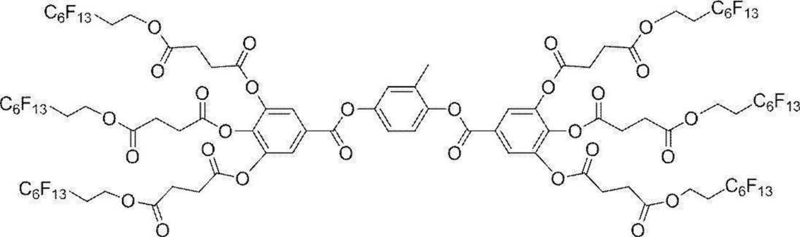
・フッ素系化合物3

上述の塗布液組成のキラル剤LC-756の処方量を調節して、塗布液B、G、および、Rを調製した。それぞれの塗布液を用いて、以下の選択反射層作製時と同様に剥離性支持体上に単一層のコレステリック液晶層を作製し、反射特性を確認したところ、作製されたコレステリック液晶層はすべて右円偏光反射層であり、選択反射の中心波長は、下記表1のとおりであった。
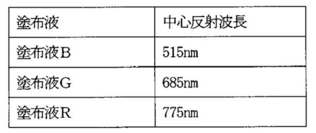
(位相差層形成用塗布液)
下記の成分を混合し、下記組成の位相差層形成用塗布液を調製した。
―――――――――――――――――――――――――――――――――
位相差層形成用塗布液の組成
―――――――――――――――――――――――――――――――――
・混合物1 100質量部
・フッ素系化合物1 0.05質量部
・フッ素系化合物2 0.01質量部
・重合開始剤IRGACURE OXE01(BASF社製)
0.75質量部
・溶媒(メチルエチルケトン) 溶質濃度が25質量%となる量
―――――――――――――――――――――――――――――――――
下記の成分を混合し、下記組成の位相差層形成用塗布液を調製した。
―――――――――――――――――――――――――――――――――
位相差層形成用塗布液の組成
―――――――――――――――――――――――――――――――――
・混合物1 100質量部
・フッ素系化合物1 0.05質量部
・フッ素系化合物2 0.01質量部
・重合開始剤IRGACURE OXE01(BASF社製)
0.75質量部
・溶媒(メチルエチルケトン) 溶質濃度が25質量%となる量
―――――――――――――――――――――――――――――――――
<セルロースアシレートフィルムの鹸化>
国際公開第2014/112575号の実施例20と同一の作製方法で、厚み40μmセルロースアシレートフィルムを作製した。
作製したセルロースアシレートフィルムを、温度60℃の誘電式加熱ロールを通過させて、フィルムの表面温度を40℃に昇温した後に、フィルムの片面に下記に示す組成のアルカリ溶液を、バーコーターを用いて塗布量14mL/m2で塗布し、110℃に加熱したスチーム式遠赤外ヒーター(ノリタケカンパニーリミテド社製)の下に10秒間滞留させた。
次いで、同じくバーコーターを用いて、純水を3mL/m2塗布した。
次いで、ファウンテンコーターによる水洗とエアナイフによる水切りを3回繰り返した後に、70℃の乾燥ゾーンに5秒間滞留させて乾燥し、鹸化処理したセルロースアシレートフィルム1を作製した。
また、膜厚が80μm、25μm、および、100μmになるよう調節して作製したセルロースアシレートフィルムを用意し、上記と同様の処理を施し、セルロースアシレートフィルム2、3、および、4を作製した。
また、膜厚が40μmになるよう調節し、さらに、残留応力が大きくなるよう延伸条件を調整して作製したセルロースアシレートフィルムを用意し、上記と同様の処理を施し、セルロースアシレートフィルム5を作製した。
セルロースアシレートフィルム1~5の面内位相差をAxoScanで測定したところ、1nmであった。
さらに、セルロースアシレートフィルム1~5を、140℃で60分間加熱した。その結果、セルロースアシレートフィルム1~4の熱収縮率が最大となる方向の収縮率は0.5%で、該方向と直交する方向の熱収縮率は0.1%であった。一方、セルロースアシレートフィルム5の熱収縮率が最大となる方向の収縮率は0.8%で、該方向と直交する方向の熱収縮率は0.7%であった。
―――――――――――――――――――――――――――――――――
アルカリ溶液の組成
―――――――――――――――――――――――――――――――――
・水酸化カリウム 4.7質量部
・水 15.7質量部
・イソプロパノール 64.8質量部
・界面活性剤(C16H33O(CH2CH2O)10H) 1.0質量部
・プロピレングリコール 14.9質量部
―――――――――――――――――――――――――――――――――
アルカリ溶液の組成
―――――――――――――――――――――――――――――――――
・水酸化カリウム 4.7質量部
・水 15.7質量部
・イソプロパノール 64.8質量部
・界面活性剤(C16H33O(CH2CH2O)10H) 1.0質量部
・プロピレングリコール 14.9質量部
―――――――――――――――――――――――――――――――――
<配向膜の形成>
上述で得られた鹸化処理したセルロースアシレートフィルム1(透明支持体)の鹸化処理面に、下記に示す組成の配向膜形成用塗布液をワイヤーバーコーターで24mL/m2塗布し、100℃の温風で120秒乾燥し、厚み0.5μmの配向膜を得た。
上述で得られた鹸化処理したセルロースアシレートフィルム1(透明支持体)の鹸化処理面に、下記に示す組成の配向膜形成用塗布液をワイヤーバーコーターで24mL/m2塗布し、100℃の温風で120秒乾燥し、厚み0.5μmの配向膜を得た。
―――――――――――――――――――――――――――――――――
配向膜形成用塗布液の組成
―――――――――――――――――――――――――――――――――
・下記に示す変性ポリビニルアルコール 28質量部
・クエン酸エステル(AS3、三共化学社製) 1.2質量部
・光開始剤(イルガキュア2959、BASF社製) 0.84質量部
・グルタルアルデヒド 2.8質量部
・水 699質量部
・メタノール 226質量部
―――――――――――――――――――――――――――――――――
配向膜形成用塗布液の組成
―――――――――――――――――――――――――――――――――
・下記に示す変性ポリビニルアルコール 28質量部
・クエン酸エステル(AS3、三共化学社製) 1.2質量部
・光開始剤(イルガキュア2959、BASF社製) 0.84質量部
・グルタルアルデヒド 2.8質量部
・水 699質量部
・メタノール 226質量部
―――――――――――――――――――――――――――――――――
(変性ポリビニルアルコール)
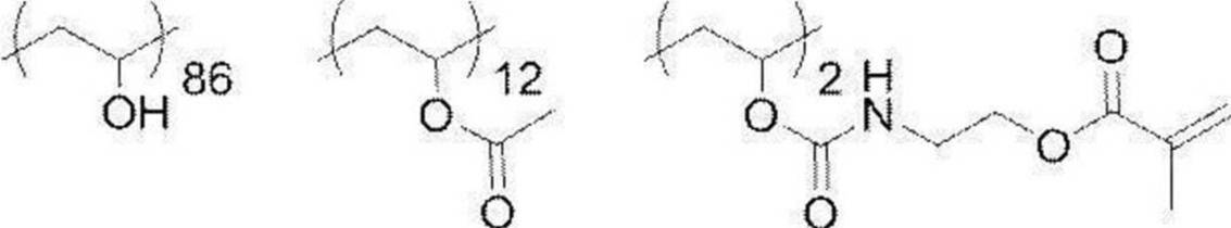
<ハーフミラーフィルムの作製>
上述作製した配向膜に、短辺方向を基準に反時計回りに31.5°回転させた方向にラビング処理(レーヨン布、圧力:0.1kgf(0.98N)、回転数:1000rpm、搬送速度:10m/min、回数:1往復)を施した。
上述作製した配向膜に、短辺方向を基準に反時計回りに31.5°回転させた方向にラビング処理(レーヨン布、圧力:0.1kgf(0.98N)、回転数:1000rpm、搬送速度:10m/min、回数:1往復)を施した。
セルロースアシレートフィルム1のラビングした表面に、位相差層形成用塗布液をワイヤーバーを用いて塗布後、乾燥させて55℃にて1分間加熱処理を行い、50℃のホットプレート上に置き、ヘレウス社製の無電極ランプ「Dバルブ」(60mW/cm2)にて6秒間、紫外線を照射し、液晶相を固定して、厚み1.9μmの位相差層を得た。このとき、位相差層のレタデーションと遅相軸角度をAxoScanで測定したところ、レタデーションは349nm、遅相軸角度は完成した合わせガラスの鉛直上方向(短辺方向)に対し、+58.5°であった。
得られた位相差層の表面に塗布液Bをワイヤーバーを用いて塗布後、乾燥させて85℃にて1分間加熱処理を行い、80℃のホットプレート上に置き、ヘレウス社製の無電極ランプ「Dバルブ」(60mW/cm2)にて6秒間、紫外線を照射し、コレステリック液晶相を固定して、厚み2.3μmのコレステリック液晶層を得た。
得られたコレステリック液晶層の表面にさらに塗布液Gをワイヤーバーを用いて塗布後、乾燥させて70℃にて1分間加熱処理を行い、75℃のホットプレート上に置き、ヘレウス社製の無電極ランプ「Dバルブ」(60mW/cm2)にて6秒間、紫外線を照射し、コレステリック液晶相を固定して、厚み0.7μmのコレステリック液晶層を得た。
得られたコレステリック液晶層の表面にさらに塗布液Rをワイヤーバーを用いて塗布後、乾燥させて70℃にて1分間加熱処理を行い、75℃のホットプレート上に置き、ヘレウス社製の無電極ランプ「Dバルブ」(60mW/cm2)にて6秒間、紫外線を照射し、コレステリック液晶相を固定して、厚み2.8μmのコレステリック液晶層を得た。
こうして位相差層および3層のコレステリック液晶層からなる選択反射層を有するハーフミラーフィルムA1を得た。ハーフミラーフィルムA1の透過スペクトルを分光光度計(日本分光社製、V-670)で測定したところ、515nm、685nm、775nmに選択反射中心波長を有する透過スペクトルが得られた。
セルロースアシレートフィルム1の代わりにセルロースアシレートフィルム2~5を使用したこと以外は、同様の手順で、ハーフミラーフィルムA2~4、および、A7を作製した。ハーフミラーフィルムA2~4、および、A7の透過スペクトルを分光光度計(日本分光社製、V-670)で測定したところ、いずれのハーフミラーフィルムにおいても、515nm、685nm、775nmに選択反射中心波長を有する透過スペクトルが得られた。
ハーフミラーフィルムA1のコレステリック液晶層の表面にVetaphone社製の装置を用いてコロナ処理(5.0kJ/cm2)を施し、ハーフミラーフィルムA5を作製した。
また、別のハーフミラーフィルムとして直線偏光反射板を用意した。
特表平9-506837号公報に記載された方法に基づいて、2,6-ポリエチレンナフタレート(PEN)とナフタレート70/テレフタレート30のコポリエステル(coPEN)の層数、厚みを調整して、ハーフミラーフィルムA6を作製した。
ハーフミラーフィルムA6の透過スペクトルを、分光光度計(日本分光社製、V-670)で測定したところ、685nmに選択反射中心波長を有する透過スペクトルが得られた。
特表平9-506837号公報に記載された方法に基づいて、2,6-ポリエチレンナフタレート(PEN)とナフタレート70/テレフタレート30のコポリエステル(coPEN)の層数、厚みを調整して、ハーフミラーフィルムA6を作製した。
ハーフミラーフィルムA6の透過スペクトルを、分光光度計(日本分光社製、V-670)で測定したところ、685nmに選択反射中心波長を有する透過スペクトルが得られた。
<ヒートシール層の作製>
(ヒートシール層形成用塗布液)
下記の成分を混合し、下記表2の組成のヒートシール層形成用塗布液H1~14を調製した。各組成物の単位は質量%である。
(ヒートシール層形成用塗布液)
下記の成分を混合し、下記表2の組成のヒートシール層形成用塗布液H1~14を調製した。各組成物の単位は質量%である。

<シリカ粒子分散液の調製>
本発明においてヒートシール層に好ましく用いられる無機微粒子としてAEROSIL RX300(日本アエロジル社製、平均一次粒子径7nm)を、固形分濃度が5質量%になるように、MiBK(メチルイソブチルケトン)へ添加し、マグネチックスターラーで30分攪拌した。その後、超音波分散機(エスエムテー社製、Ultrasonic Homogenizer UH-600S)で10分間、超音波分散し、シリカ粒子分散液を作製した。
得られた分散液から一部を平均二次粒子径測定用に採取し、Microtrac MT3000(マイクロトラックベル社製)を用いて、分散液中のシリカ粒子の平均二次粒子径を測定したところ、190nmであった。
IPA-ST-ZL(日産化学社製、平均一次粒子径70~100nm)、MEK-ST-ZL(日産化学社製、平均一次粒子径70~100nm)、MEK-ST-L(日産化学社製、平均一次粒子径40~50nm)は、市販のコロイダルシリカ分散液を用いた(固形分濃度30質量%)。
表中、無機微粒子の添加量は分散液の添加量を記載した。
ヒートシール樹脂には、市販のポリビニルアセタール樹脂から、エスレックKS10(積水化学工業社製)、エスレックBL-5(積水化学工業社製)を用いた。
<投映像表示用積層フィルムの作製1>
ハーフミラーフィルムA1の透明支持体のコレステリック液晶を塗布していない側の面に、ヒートシール層形成用塗布液H1~14を、ワイヤーバーを用いて塗布後、乾燥させて100℃にて1分間加熱処理を行った。
こうして透明支持体の一面に、位相差層、および、3層のコレステリック液晶層(選択反射層)を持ち、セルロースアシレートフィルムの逆の面に厚み1.0μmのヒートシール層を持つ投映像表示用積層フィルムAH1~12(実施例1~12)、および、BH1~2(比較例1および2)を得た。
ハーフミラーフィルムA1の透明支持体のコレステリック液晶を塗布していない側の面に、ヒートシール層形成用塗布液H1~14を、ワイヤーバーを用いて塗布後、乾燥させて100℃にて1分間加熱処理を行った。
こうして透明支持体の一面に、位相差層、および、3層のコレステリック液晶層(選択反射層)を持ち、セルロースアシレートフィルムの逆の面に厚み1.0μmのヒートシール層を持つ投映像表示用積層フィルムAH1~12(実施例1~12)、および、BH1~2(比較例1および2)を得た。
ハーフミラーフィルムA1の透明支持体のコレステリック液晶を塗布していない側の面に、ヒートシール層形成用塗布液H5を、ワイヤーバー、および、アプリケータ―を適宜用いて乾燥後のヒートシール層の厚みがそれぞれ0.1μm、2.5μm、5μm、10μm、40μm、および、100μmとなるように塗布後、乾燥させて100℃にて1分間加熱処理を行った。
こうして透明支持体の一面に、位相差層、および、3層のコレステリック液晶層(選択反射層)を持ち、セルロースアシレートフィルムの逆の面に厚みがそれぞれ0.1μm、2.5μm、5μm、10μm、40μm、および、100μmのヒートシール層を持つ投映像表示用積層フィルムAH17~21(実施例13~17)、および、BH3(比較例3)を得た。
こうして透明支持体の一面に、位相差層、および、3層のコレステリック液晶層(選択反射層)を持ち、セルロースアシレートフィルムの逆の面に厚みがそれぞれ0.1μm、2.5μm、5μm、10μm、40μm、および、100μmのヒートシール層を持つ投映像表示用積層フィルムAH17~21(実施例13~17)、および、BH3(比較例3)を得た。
ハーフミラーフィルムA2の透明支持体のコレステリック液晶を塗布していない側の面に、ヒートシール層形成用塗布液H5を、ワイヤーバーを用いて塗布後、乾燥させて100℃にて1分間加熱処理を行った。
こうして透明支持体の一面に、位相差層、および、3層のコレステリック液晶層(選択反射層)を持ち、セルロースアシレートフィルムの逆の面に厚みが1.0μmのヒートシール層を持つ投映像表示用積層フィルムAH13(実施例18)を得た。
こうして透明支持体の一面に、位相差層、および、3層のコレステリック液晶層(選択反射層)を持ち、セルロースアシレートフィルムの逆の面に厚みが1.0μmのヒートシール層を持つ投映像表示用積層フィルムAH13(実施例18)を得た。
ハーフミラーフィルムA3の透明支持体のコレステリック液晶を塗布していない側の面に、ヒートシール層形成用塗布液H5を、ワイヤーバーを用いて塗布後、乾燥させて100℃にて1分間加熱処理を行った。
こうして透明支持体の一面に、位相差層、および、3層のコレステリック液晶層(選択反射層)を持ち、セルロースアシレートフィルムの逆の面に厚みが1.0μmのヒートシール層を持つ投映像表示用積層フィルムAH14(実施例19)を得た。
こうして透明支持体の一面に、位相差層、および、3層のコレステリック液晶層(選択反射層)を持ち、セルロースアシレートフィルムの逆の面に厚みが1.0μmのヒートシール層を持つ投映像表示用積層フィルムAH14(実施例19)を得た。
ハーフミラーフィルムA4の透明支持体のコレステリック液晶を塗布していない側の面に、ヒートシール層形成用塗布液H5を、ワイヤーバーを用いて塗布後、乾燥させて100℃にて1分間加熱処理を行った。
こうして透明支持体の一面に、位相差層、および、3層のコレステリック液晶層(選択反射層)を持ち、セルロースアシレートフィルムの逆の面に厚みが1.0μmのヒートシール層を持つ投映像表示用積層フィルムBH4(比較例4)を得た。
こうして透明支持体の一面に、位相差層、および、3層のコレステリック液晶層(選択反射層)を持ち、セルロースアシレートフィルムの逆の面に厚みが1.0μmのヒートシール層を持つ投映像表示用積層フィルムBH4(比較例4)を得た。
ハーフミラーフィルムA5の透明支持体のコレステリック液晶を塗布していない側の面に、ヒートシール層形成用塗布液H5を、ワイヤーバーを用いて塗布後、乾燥させて100℃にて1分間加熱処理を行った。
こうして透明支持体の一面に、位相差層、および、3層のコレステリック液晶層(選択反射層)を持ち、セルロースアシレートフィルムの逆の面に厚みが1.0μmのヒートシール層を持つ投映像表示用積層フィルムAH15(実施例20)を得た。
こうして透明支持体の一面に、位相差層、および、3層のコレステリック液晶層(選択反射層)を持ち、セルロースアシレートフィルムの逆の面に厚みが1.0μmのヒートシール層を持つ投映像表示用積層フィルムAH15(実施例20)を得た。
ハーフミラーフィルムA6の透明支持体のコレステリック液晶を塗布していない側の面に、ヒートシール層形成用塗布液H5を、ワイヤーバーを用いて塗布後、乾燥させて100℃にて1分間加熱処理を行った。
こうして透明支持体の一面に、位相差層、および、3層のコレステリック液晶層(選択反射層)を持ち、セルロースアシレートフィルムの逆の面に厚みが1.0μmのヒートシール層を持つ投映像表示用積層フィルムAH16(実施例21)を得た。
こうして透明支持体の一面に、位相差層、および、3層のコレステリック液晶層(選択反射層)を持ち、セルロースアシレートフィルムの逆の面に厚みが1.0μmのヒートシール層を持つ投映像表示用積層フィルムAH16(実施例21)を得た。
ハーフミラーフィルムA7の透明支持体のコレステリック液晶を塗布していない側の面に、ヒートシール層形成用塗布液H5を、ワイヤーバーを用いて塗布後、乾燥させて100℃にて1分間加熱処理を行った。
こうして透明支持体の一面に、位相差層、および、3層のコレステリック液晶層(選択反射層)を持ち、セルロースアシレートフィルムの逆の面に厚みが1.0μmのヒートシール層を持つ投映像表示用積層フィルムAH22(実施例22)を得た。
こうして透明支持体の一面に、位相差層、および、3層のコレステリック液晶層(選択反射層)を持ち、セルロースアシレートフィルムの逆の面に厚みが1.0μmのヒートシール層を持つ投映像表示用積層フィルムAH22(実施例22)を得た。
<合わせガラスの作製>
縦260mm×横330mm、厚み2mmの凸の曲面ガラス板の上に、縦220×横290mmの投映像表示用積層フィルムAH1~22、および、BH1~4を、ヒートシール層側の面を下にしてガラス板の中央部に配置した。これにより、第1ガラス板、ヒートシール層、透明支持体、位相差層、および、選択反射層を、この順番で有する積層体を形成した。
この積層体の上に、縦260mm×横330mm、厚み0.38mmの積水化学工業社製のPVBフィルム(中間膜)を配置し、さらにその上に、縦260mm×横330mm、厚み2mmの凸の曲面ガラス板(第2ガラス板)を配置した。これを90℃、10kPa(0.1気圧)下で1時間保持した後に、オートクレーブ(栗原製作所製)にて140℃、1.3Mpa(13気圧)で60分間加熱して気泡を除去し、合わせガラスA~Z(実施例1~22、比較例1~4)を得た。
この合わせガラスA~Zは、図3に示す合わせガラスと同様の層構成を有するものである。
(弾性率の測定)
ハーフミラーフィルムA1~7の試料10mm×150mmを、25℃、相対湿度60%で2時間以上調湿した後に東洋ボールドウィン社製の万能引っ張り試験機“STM T50BP”を用い、25℃、60RH%の雰囲気中、引張速度10%/分で0.5%伸びにおける応力を測定し、弾性率を求めた。
ハーフミラーフィルムA1~7の試料10mm×150mmを、25℃、相対湿度60%で2時間以上調湿した後に東洋ボールドウィン社製の万能引っ張り試験機“STM T50BP”を用い、25℃、60RH%の雰囲気中、引張速度10%/分で0.5%伸びにおける応力を測定し、弾性率を求めた。
(剛性)
ハーフミラーフィルムA1~7の剛性[N・mm]を、ハーフミラーフィルムの厚みd[μm]と、上記測定で求めた弾性率σ[MPa]を用い、下記式から算出した。
剛性=σ×(d/1000)3
ハーフミラーフィルムA1~7の剛性[N・mm]を、ハーフミラーフィルムの厚みd[μm]と、上記測定で求めた弾性率σ[MPa]を用い、下記式から算出した。
剛性=σ×(d/1000)3
(静摩擦係数の測定)
静摩擦係数測定機HEIDON-10(新東科学社製)を用いて、投映像表示用積層フィルムのヒートシール層面とガラス(フロート製法で作製された板ガラス(フロートガラス))の静摩擦係数を測定し、下記基準で評価した。
A:静摩擦係数が0.8以下
B:静摩擦係数が0.8よりも大きく、1.0以下
C:静摩擦係数が1.0よりも大きい
静摩擦係数測定機HEIDON-10(新東科学社製)を用いて、投映像表示用積層フィルムのヒートシール層面とガラス(フロート製法で作製された板ガラス(フロートガラス))の静摩擦係数を測定し、下記基準で評価した。
A:静摩擦係数が0.8以下
B:静摩擦係数が0.8よりも大きく、1.0以下
C:静摩擦係数が1.0よりも大きい
(ヒートシール層のガラスに対する貼りつき性の評価(貼付性))
投映像表示用積層フィルムAH1~22、および、BH1~4について、液晶層塗布面と逆面の表面とガラスを貼り合わせた際の貼り付き性を、下記の基準で評価した。貼り付き感が無くなるほど滑り性が向上し、合わせガラス加工時の積層体のハンドリング性が向上し、シワが発生しにくくなる効果がある。
A:貼り付き感が全く無い。
B:貼り付き感が殆ど無い。
C:貼り付き感が強い。
投映像表示用積層フィルムAH1~22、および、BH1~4について、液晶層塗布面と逆面の表面とガラスを貼り合わせた際の貼り付き性を、下記の基準で評価した。貼り付き感が無くなるほど滑り性が向上し、合わせガラス加工時の積層体のハンドリング性が向上し、シワが発生しにくくなる効果がある。
A:貼り付き感が全く無い。
B:貼り付き感が殆ど無い。
C:貼り付き感が強い。
(シワの評価)
各合わせガラスの加工後に、積層体にシワが発生しているかを下記基準で目視にて評価した。
A:シワの発生が全くない。
B:微細なシワはないが、僅かな波打ちが見える。
C:微細なシワの発生が有る。
D:大きなうねり状のシワが有る。
各合わせガラスの加工後に、積層体にシワが発生しているかを下記基準で目視にて評価した。
A:シワの発生が全くない。
B:微細なシワはないが、僅かな波打ちが見える。
C:微細なシワの発生が有る。
D:大きなうねり状のシワが有る。
(画像視認性の評価)
画像視認性は各合わせガラスの凹面に図4に示すようにp偏光を当て、映像を投映し、発生した虚像の歪みを画像視認性として下記基準で評価した。
A:歪み無し。
B:殆ど歪み無し。
C:良く見ると僅かな歪みが有るが、特に違和感はない。
D:歪み有り。
画像視認性は各合わせガラスの凹面に図4に示すようにp偏光を当て、映像を投映し、発生した虚像の歪みを画像視認性として下記基準で評価した。
A:歪み無し。
B:殆ど歪み無し。
C:良く見ると僅かな歪みが有るが、特に違和感はない。
D:歪み有り。
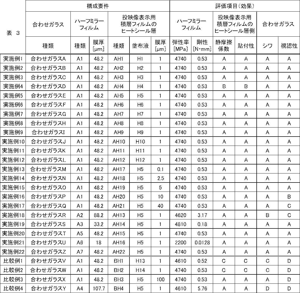
合わせガラスA~UおよびZ(実施例1~22)は、ヒートシール層のガラスに対する静摩擦係数が低いため、貼りつき性が弱く、合わせガラスにおいても目立つシワはなく、また、画像の視認性も大きな歪みは感じられなかった。合わせガラスA~C(実施例1~3)、E~UおよびZ(実施例5~22)は、ヒートシール層のガラスに対する静摩擦係数が特に低いため、ヒートシール層のガラスに対する貼りつき性が良好であり、合わせガラス時のハンドリング性が向上し、シワがさらに良化した。中でも、評価には表れていないが、合わせガラスZ(実施例22)は、セルロースアシレートフィルムの熱収縮により、シワが特に良化した。合わせガラスA~O(実施例1~15)、S~U(実施例19~21)およびZ(実施例22)は、ヒートシール層の膜厚が特に薄く、かつ、ハーフミラーフィルムの膜厚も薄いため、画像の視認性はさらに良好であった。
合わせガラスVおよびW(比較例1および2)は、ヒートシール層のガラスに対する静摩擦係数が高く、貼りつき性が強いため、合わせガラス時のハンドリング性が低く、シワが発生した。
合わせガラスX(比較例3)は、ヒートシール層が厚く、虚像の歪みが発生し、画像の視認性が低下した。
また、合わせガラスY(比較例4)は、ハーフミラーフィルムの剛性が高く、曲面ガラスへの追従性が低いため、合わせガラスにおいて、大きなうねり状のシワが発生した。
合わせガラスVおよびW(比較例1および2)は、ヒートシール層のガラスに対する静摩擦係数が高く、貼りつき性が強いため、合わせガラス時のハンドリング性が低く、シワが発生した。
合わせガラスX(比較例3)は、ヒートシール層が厚く、虚像の歪みが発生し、画像の視認性が低下した。
また、合わせガラスY(比較例4)は、ハーフミラーフィルムの剛性が高く、曲面ガラスへの追従性が低いため、合わせガラスにおいて、大きなうねり状のシワが発生した。
1 透明支持体
2 位相差層
3 選択反射層
4 ヒートシール層
5 中間膜
6 第1ガラス板
7 第2ガラス板
10 ハーフミラーフィルム
100 プロジェクター(p偏光画像)
2 位相差層
3 選択反射層
4 ヒートシール層
5 中間膜
6 第1ガラス板
7 第2ガラス板
10 ハーフミラーフィルム
100 プロジェクター(p偏光画像)
Claims (9)
- 波長選択的に光を反射する選択反射層を含むハーフミラーフィルムと、前記ハーフミラーフィルムの一方の面に積層されるヒートシール層と、を有し、
前記ハーフミラーフィルムの25℃における剛性が4.0N・mm以下であり、
前記ヒートシール層は、厚みが40μm以下で、熱可塑性樹脂を含有し、前記ハーフミラーフィルムとは逆の面の静摩擦係数が1.0以下である、投映像表示用積層フィルム。 - 前記ハーフミラーフィルムの剛性が1.0N・mm以下である、請求項1に記載の投映像表示用積層フィルム。
- 前記ヒートシール層の厚みが10μm以下である、請求項1または2に記載の投映像表示用積層フィルム。
- 前記ヒートシール層がポリビニルアセタール樹脂を含む、請求項1~3のいずれか1項に記載の投映像表示用積層フィルム。
- 前記ヒートシール層が平均一次粒子径が5~380nmの微粒子を含有する、請求項1~4のいずれか1項に記載の投映像表示用積層フィルム。
- 前記ヒートシール層が、一次粒子の凝集体である二次粒子を形成する微粒子を含有するものであり、かつ、
前記一次粒子の平均粒子径が5~50nmで、前記二次粒子の平均粒子径が50~380nmである、請求項1~4のいずれか1項に記載の投映像表示用積層フィルム。 - 前記ヒートシール層が、前記微粒子を3~30質量%含有する、請求項5または6に記載の投映像表示用積層フィルム。
- 請求項1~7のいずれか1項に記載の投映像表示用積層フィルムと、前記投映像表示用積層フィルムの前記選択反射層に隣接する中間膜との積層体を、2枚のガラス板で挟持した、投映像表示用の合わせガラス。
- 請求項8に記載の投映像表示用の合わせガラスに、p偏光を出射する光源から画像を投映する、画像表示システム。
Priority Applications (4)
| Application Number | Priority Date | Filing Date | Title |
|---|---|---|---|
| JP2021504112A JP7133703B2 (ja) | 2019-03-06 | 2020-03-03 | 投映像表示用積層フィルム、投映像表示用の合わせガラス、および、画像表示システム |
| CN202080018223.4A CN113498487B (zh) | 2019-03-06 | 2020-03-03 | 投影图像显示用层叠膜、投影图像显示用的夹层玻璃及图像显示系统 |
| EP20767141.3A EP3936924A4 (en) | 2019-03-06 | 2020-03-03 | LAMINATED FILM FOR DISPLAYING A PROJECTION IMAGE, LAMINATED GLASS FOR DISPLAYING A PROJECTION IMAGE AND IMAGE DISPLAY SYSTEM |
| US17/464,840 US20210397011A1 (en) | 2019-03-06 | 2021-09-02 | Projection-image-displaying laminate film, projection-image-displaying laminated glass, and image display system |
Applications Claiming Priority (6)
| Application Number | Priority Date | Filing Date | Title |
|---|---|---|---|
| JP2019040484 | 2019-03-06 | ||
| JP2019-040484 | 2019-03-06 | ||
| JP2019-177867 | 2019-09-27 | ||
| JP2019177867 | 2019-09-27 | ||
| JP2019191993 | 2019-10-21 | ||
| JP2019-191993 | 2019-10-21 |
Related Child Applications (1)
| Application Number | Title | Priority Date | Filing Date |
|---|---|---|---|
| US17/464,840 Continuation US20210397011A1 (en) | 2019-03-06 | 2021-09-02 | Projection-image-displaying laminate film, projection-image-displaying laminated glass, and image display system |
Publications (1)
| Publication Number | Publication Date |
|---|---|
| WO2020179787A1 true WO2020179787A1 (ja) | 2020-09-10 |
Family
ID=72337492
Family Applications (1)
| Application Number | Title | Priority Date | Filing Date |
|---|---|---|---|
| PCT/JP2020/008919 WO2020179787A1 (ja) | 2019-03-06 | 2020-03-03 | 投映像表示用積層フィルム、投映像表示用の合わせガラス、および、画像表示システム |
Country Status (5)
| Country | Link |
|---|---|
| US (1) | US20210397011A1 (ja) |
| EP (1) | EP3936924A4 (ja) |
| JP (1) | JP7133703B2 (ja) |
| CN (1) | CN113498487B (ja) |
| WO (1) | WO2020179787A1 (ja) |
Cited By (1)
| Publication number | Priority date | Publication date | Assignee | Title |
|---|---|---|---|---|
| WO2024043305A1 (ja) * | 2022-08-25 | 2024-02-29 | 富士フイルム株式会社 | 反射フィルム付き曲面ガラスの製造方法、反射フィルム付き曲面ガラス、および、ヘッドアップディスプレイシステム |
Families Citing this family (3)
| Publication number | Priority date | Publication date | Assignee | Title |
|---|---|---|---|---|
| JP6975257B2 (ja) | 2017-12-28 | 2021-12-01 | 富士フイルム株式会社 | 光学素子および導光素子 |
| WO2019194291A1 (ja) * | 2018-04-05 | 2019-10-10 | 富士フイルム株式会社 | 光学素子および導光素子 |
| WO2024000217A1 (zh) * | 2022-06-29 | 2024-01-04 | 京东方科技集团股份有限公司 | 投影装置及显示系统 |
Citations (66)
| Publication number | Priority date | Publication date | Assignee | Title |
|---|---|---|---|---|
| US2367661A (en) | 1941-12-31 | 1945-01-23 | Du Pont | Process of photopolymerization |
| US2367670A (en) | 1941-12-31 | 1945-01-23 | Du Pont | Cementing process |
| US2448828A (en) | 1946-09-04 | 1948-09-07 | Du Pont | Photopolymerization |
| US2722512A (en) | 1952-10-23 | 1955-11-01 | Du Pont | Photopolymerization process |
| US2951758A (en) | 1957-05-17 | 1960-09-06 | Du Pont | Photopolymerizable compositions and elements |
| US3046127A (en) | 1957-10-07 | 1962-07-24 | Du Pont | Photopolymerizable compositions, elements and processes |
| US3549367A (en) | 1968-05-24 | 1970-12-22 | Du Pont | Photopolymerizable compositions containing triarylimidazolyl dimers and p-aminophenyl ketones |
| JPS505330B1 (ja) | 1971-07-12 | 1975-03-03 | ||
| US4212970A (en) | 1977-11-28 | 1980-07-15 | Fuji Photo Film Co., Ltd. | 2-Halomethyl-5-vinyl-1,3,4-oxadiazole compounds |
| US4239850A (en) | 1977-11-29 | 1980-12-16 | Fuji Photo Film Co., Ltd. | Photopolymerizable composition |
| JPS60105667A (ja) | 1983-10-12 | 1985-06-11 | ヘキスト・アクチエンゲゼルシヤフト | トリクロルメチル基を有する感光性化合物及びその製法 |
| US4683327A (en) | 1985-06-24 | 1987-07-28 | Celanese Corporation | Anisotropic heat-curable acrylic terminated monomers |
| JPS6340799B2 (ja) | 1978-07-14 | 1988-08-12 | Basf Ag | |
| JPH01272551A (ja) | 1988-04-22 | 1989-10-31 | Dainippon Printing Co Ltd | 重合性2官能アクリレートモノマー |
| JPH02141720A (ja) | 1988-11-23 | 1990-05-31 | Nippon Denso Co Ltd | ヘッドアップディスプレイ装置 |
| US5013134A (en) | 1989-09-28 | 1991-05-07 | Hughes Aircraft Company | Ghost-free automotive head-up display employing a wedged windshield |
| JPH0529234B2 (ja) | 1984-11-27 | 1993-04-28 | Esupe Fuaburiiku Fuarumatsuoiteitsusheru Pureparaate Gmbh Unto Co Kg | |
| JPH0616616A (ja) | 1992-07-03 | 1994-01-25 | Canon Inc | 反応性液晶性化合物、高分子液晶化合物、液晶組成物および液晶素子 |
| JPH07110469A (ja) | 1993-08-16 | 1995-04-25 | Dainippon Ink & Chem Inc | 液晶表示素子及びその製造方法 |
| WO1995022586A1 (de) | 1994-02-19 | 1995-08-24 | Basf Aktiengesellschaft | Neue polymerisierbare flüssigkristalline verbindungen |
| WO1995024455A1 (de) | 1994-03-11 | 1995-09-14 | Basf Aktiengesellschaft | Neue polymerisierbare flüssigkristalline verbindungen |
| JPH07270711A (ja) | 1994-03-30 | 1995-10-20 | Canon Inc | 情報表示装置 |
| WO1997000600A2 (de) | 1995-09-01 | 1997-01-09 | Basf Aktiengesellschaft | Polymerisierbare flüssigkristalline verbindungen |
| US5622648A (en) | 1993-10-15 | 1997-04-22 | Merck Patent Gesellschaft Mit Beschrankter Haftung | Reactive liquid crystal compounds |
| JPH09506837A (ja) | 1993-12-21 | 1997-07-08 | ミネソタ・マイニング・アンド・マニュファクチュアリング・カンパニー | 多層光学フィルム |
| JPH1029997A (ja) | 1996-03-04 | 1998-02-03 | Ciba Specialty Chem Holding Inc | アルキルフェニルビスアシルホスフィンオキサイドおよび光開始剤混合物 |
| JPH1096874A (ja) | 1996-05-24 | 1998-04-14 | Asahi Glass Co Ltd | 車両用ウインドシールドガラスおよびヘッドアップディスプレイ装置 |
| JPH1095788A (ja) | 1996-08-28 | 1998-04-14 | Ciba Specialty Chem Holding Inc | 光開始剤としての分子錯化合物 |
| WO1998023580A1 (de) | 1996-11-27 | 1998-06-04 | Basf Aktiengesellschaft | Polymerisierbare oligomesogene |
| US5770107A (en) | 1995-10-05 | 1998-06-23 | Merck Patent Gesellschaft Mit Beschrankter Haftung | Reactive liquid crystalline compound |
| WO1998052905A1 (en) | 1997-05-22 | 1998-11-26 | Rolic Ag | New polymerisable liquid crystalline compounds |
| JPH1180081A (ja) | 1997-09-05 | 1999-03-23 | Dainippon Ink & Chem Inc | 液晶性(メタ)アクリレート化合物と組成物及びこれを用いた光学異方体 |
| JP2000066385A (ja) | 1998-08-18 | 2000-03-03 | Ciba Specialty Chem Holding Inc | 高感度で高レジスト厚さのi線ホトレジスト用スルホニルオキシム類 |
| JP2000080068A (ja) | 1998-06-26 | 2000-03-21 | Ciba Specialty Chem Holding Inc | 新規o―アシルオキシム光開始剤 |
| JP2000221449A (ja) | 1999-01-29 | 2000-08-11 | Arisawa Mfg Co Ltd | 映像装置 |
| JP2001233842A (ja) | 1999-12-15 | 2001-08-28 | Ciba Specialty Chem Holding Inc | オキシムエステルの光開始剤 |
| JP2001328973A (ja) | 2000-03-13 | 2001-11-27 | Fuji Photo Film Co Ltd | 重合性液晶化合物および光学異方性素子 |
| JP2002080478A (ja) | 2000-06-27 | 2002-03-19 | Fuji Photo Film Co Ltd | 光反応型光学活性化合物、光反応型カイラル剤、液晶組成物、液晶カラーフィルタ、光学フィルム、記録媒体、及び液晶の捻れ構造を変化させる方法 |
| JP2002080851A (ja) | 2000-06-27 | 2002-03-22 | Fuji Photo Film Co Ltd | 光反応型カイラル剤、液晶組成物、液晶カラーフィルタ、光学フィルム、記録媒体、及び液晶の捻れ構造を変化させる方法 |
| JP2002302487A (ja) | 2000-12-14 | 2002-10-18 | Fuji Photo Film Co Ltd | 光学活性化合物、光反応型キラル剤、液晶組成物、液晶の螺旋構造を変化させる方法、液晶の螺旋構造を固定化する方法、液晶カラーフィルター、光学フィルムおよび記録媒体 |
| JP2003098470A (ja) | 2001-09-21 | 2003-04-03 | Asahi Glass Co Ltd | ヘッドアップディスプレイ装置 |
| JP2003287623A (ja) | 2002-01-23 | 2003-10-10 | Nitto Denko Corp | 光学フィルム、その製造方法、およびこれを用いた位相差フィルムならびに偏光板 |
| JP2006512622A (ja) | 2002-12-31 | 2006-04-13 | スリーエム イノベイティブ プロパティズ カンパニー | 偏光光源および広角p偏光反射偏光子を備えたヘッドアップディスプレイ |
| JP2006342166A (ja) | 2001-06-11 | 2006-12-21 | Ciba Specialty Chem Holding Inc | 組み合わされた構造を有するオキシムエステルの光開始剤 |
| JP2007523369A (ja) | 2004-02-04 | 2007-08-16 | マイクロビジョン,インク. | 走査ビームヘッドアップ表示装置および関連システム、および方法 |
| JP2007272185A (ja) | 2006-03-10 | 2007-10-18 | Fujifilm Corp | 組成物、位相差板、液晶表示装置、平均チルト角調整剤、平均チルト角の調整方法 |
| JP4223071B2 (ja) | 2006-12-27 | 2009-02-12 | 株式会社Adeka | オキシムエステル化合物及び該化合物を含有する光重合開始剤 |
| JP2009150947A (ja) | 2007-12-19 | 2009-07-09 | Hitachi Ltd | 車両用ヘッドアップディスプレイ装置 |
| JP2010145745A (ja) | 2008-12-18 | 2010-07-01 | Equos Research Co Ltd | 画像形成装置、及び、ヘッドアップディスプレイ装置 |
| JP2010181852A (ja) | 2008-07-14 | 2010-08-19 | Fujifilm Corp | 光学異方性膜、光学異方性膜の製造方法、液晶セル用基板、及び液晶表示装置 |
| JP2010262028A (ja) | 2009-04-30 | 2010-11-18 | Nippon Steel Chem Co Ltd | ブラックマトリックス用感光性樹脂組成物 |
| JP2011505330A (ja) | 2007-12-07 | 2011-02-24 | サン−ゴバン グラス フランス | 合わせガラスからなる曲面の車両用フロントガラス |
| JP2012203237A (ja) | 2011-03-25 | 2012-10-22 | Fujifilm Corp | 光反射性フィルムの製造方法 |
| JP2012208494A (ja) | 2011-03-17 | 2012-10-25 | Fujifilm Corp | 着色感放射線性組成物、着色硬化膜、カラーフィルタ及びカラーフィルタの製造方法、固体撮像素子、液晶表示装置、並びに、染料の製造方法 |
| JP2012226303A (ja) | 2011-12-21 | 2012-11-15 | Pioneer Electronic Corp | 光源ユニット及びヘッドアップディスプレイ |
| JP2013113913A (ja) | 2011-11-25 | 2013-06-10 | Fujifilm Corp | フィルムおよびその製造方法 |
| JP2013114249A (ja) | 2011-12-01 | 2013-06-10 | Toppan Printing Co Ltd | 黒色感光性樹脂組成物およびカラーフィルタ |
| JP2013228674A (ja) | 2012-03-28 | 2013-11-07 | Nippon Seiki Co Ltd | 車両用表示装置 |
| JP2014500852A (ja) | 2010-10-05 | 2014-01-16 | ビーエーエスエフ ソシエタス・ヨーロピア | ベンゾカルバゾール化合物のオキシムエステル誘導体ならびに前記誘導体の光重合性の組成物における光開始剤としての使用 |
| JP2014034581A (ja) | 2012-08-07 | 2014-02-24 | Fujifilm Corp | 液晶組成物、高分子、フィルムおよびコレステリック液晶 |
| WO2014112575A1 (ja) | 2013-01-18 | 2014-07-24 | 富士フイルム株式会社 | 光学フィルム、偏光板、及び画像表示装置 |
| JP2014137466A (ja) | 2013-01-16 | 2014-07-28 | Jsr Corp | 感放射線性着色組成物、着色硬化膜及び表示素子 |
| WO2016052367A1 (ja) | 2014-09-29 | 2016-04-07 | 富士フイルム株式会社 | 投映像表示用部材および投映像表示システム |
| JP2017015902A (ja) | 2015-06-30 | 2017-01-19 | パナソニックIpマネジメント株式会社 | 表示装置、表示方法および表示媒体 |
| WO2018110066A1 (ja) * | 2016-12-13 | 2018-06-21 | 富士フイルム株式会社 | ウインドシールドガラス、ヘッドアップディスプレイシステム、および積層フィルム |
| WO2019050019A1 (ja) * | 2017-09-07 | 2019-03-14 | 富士フイルム株式会社 | 投映像表示用ハーフミラーフィルム、投映像表示用の合わせガラス、および、画像表示システム |
Family Cites Families (3)
| Publication number | Priority date | Publication date | Assignee | Title |
|---|---|---|---|---|
| JP5470048B2 (ja) * | 2007-11-30 | 2014-04-16 | 住友化学株式会社 | 高弾性率粘着剤層を有する偏光板及びそれを用いた画像表示装置 |
| CN106458683A (zh) * | 2014-05-15 | 2017-02-22 | 旭硝子株式会社 | 玻璃物品以及玻璃物品的制造方法 |
| JP6602727B2 (ja) * | 2016-06-06 | 2019-11-06 | 富士フイルム株式会社 | ヘッドアップディスプレイシステム |
-
2020
- 2020-03-03 WO PCT/JP2020/008919 patent/WO2020179787A1/ja unknown
- 2020-03-03 EP EP20767141.3A patent/EP3936924A4/en active Pending
- 2020-03-03 CN CN202080018223.4A patent/CN113498487B/zh active Active
- 2020-03-03 JP JP2021504112A patent/JP7133703B2/ja active Active
-
2021
- 2021-09-02 US US17/464,840 patent/US20210397011A1/en active Pending
Patent Citations (67)
| Publication number | Priority date | Publication date | Assignee | Title |
|---|---|---|---|---|
| US2367670A (en) | 1941-12-31 | 1945-01-23 | Du Pont | Cementing process |
| US2367661A (en) | 1941-12-31 | 1945-01-23 | Du Pont | Process of photopolymerization |
| US2448828A (en) | 1946-09-04 | 1948-09-07 | Du Pont | Photopolymerization |
| US2722512A (en) | 1952-10-23 | 1955-11-01 | Du Pont | Photopolymerization process |
| US2951758A (en) | 1957-05-17 | 1960-09-06 | Du Pont | Photopolymerizable compositions and elements |
| US3046127A (en) | 1957-10-07 | 1962-07-24 | Du Pont | Photopolymerizable compositions, elements and processes |
| US3549367A (en) | 1968-05-24 | 1970-12-22 | Du Pont | Photopolymerizable compositions containing triarylimidazolyl dimers and p-aminophenyl ketones |
| JPS505330B1 (ja) | 1971-07-12 | 1975-03-03 | ||
| US4212970A (en) | 1977-11-28 | 1980-07-15 | Fuji Photo Film Co., Ltd. | 2-Halomethyl-5-vinyl-1,3,4-oxadiazole compounds |
| US4239850A (en) | 1977-11-29 | 1980-12-16 | Fuji Photo Film Co., Ltd. | Photopolymerizable composition |
| JPS6340799B2 (ja) | 1978-07-14 | 1988-08-12 | Basf Ag | |
| JPS60105667A (ja) | 1983-10-12 | 1985-06-11 | ヘキスト・アクチエンゲゼルシヤフト | トリクロルメチル基を有する感光性化合物及びその製法 |
| JPH0529234B2 (ja) | 1984-11-27 | 1993-04-28 | Esupe Fuaburiiku Fuarumatsuoiteitsusheru Pureparaate Gmbh Unto Co Kg | |
| US4683327A (en) | 1985-06-24 | 1987-07-28 | Celanese Corporation | Anisotropic heat-curable acrylic terminated monomers |
| JPH01272551A (ja) | 1988-04-22 | 1989-10-31 | Dainippon Printing Co Ltd | 重合性2官能アクリレートモノマー |
| JPH02141720A (ja) | 1988-11-23 | 1990-05-31 | Nippon Denso Co Ltd | ヘッドアップディスプレイ装置 |
| US5013134A (en) | 1989-09-28 | 1991-05-07 | Hughes Aircraft Company | Ghost-free automotive head-up display employing a wedged windshield |
| JPH0616616A (ja) | 1992-07-03 | 1994-01-25 | Canon Inc | 反応性液晶性化合物、高分子液晶化合物、液晶組成物および液晶素子 |
| JPH07110469A (ja) | 1993-08-16 | 1995-04-25 | Dainippon Ink & Chem Inc | 液晶表示素子及びその製造方法 |
| US5622648A (en) | 1993-10-15 | 1997-04-22 | Merck Patent Gesellschaft Mit Beschrankter Haftung | Reactive liquid crystal compounds |
| JPH09506837A (ja) | 1993-12-21 | 1997-07-08 | ミネソタ・マイニング・アンド・マニュファクチュアリング・カンパニー | 多層光学フィルム |
| WO1995022586A1 (de) | 1994-02-19 | 1995-08-24 | Basf Aktiengesellschaft | Neue polymerisierbare flüssigkristalline verbindungen |
| WO1995024455A1 (de) | 1994-03-11 | 1995-09-14 | Basf Aktiengesellschaft | Neue polymerisierbare flüssigkristalline verbindungen |
| JPH07270711A (ja) | 1994-03-30 | 1995-10-20 | Canon Inc | 情報表示装置 |
| WO1997000600A2 (de) | 1995-09-01 | 1997-01-09 | Basf Aktiengesellschaft | Polymerisierbare flüssigkristalline verbindungen |
| US5770107A (en) | 1995-10-05 | 1998-06-23 | Merck Patent Gesellschaft Mit Beschrankter Haftung | Reactive liquid crystalline compound |
| JPH1029997A (ja) | 1996-03-04 | 1998-02-03 | Ciba Specialty Chem Holding Inc | アルキルフェニルビスアシルホスフィンオキサイドおよび光開始剤混合物 |
| JPH1096874A (ja) | 1996-05-24 | 1998-04-14 | Asahi Glass Co Ltd | 車両用ウインドシールドガラスおよびヘッドアップディスプレイ装置 |
| JPH1095788A (ja) | 1996-08-28 | 1998-04-14 | Ciba Specialty Chem Holding Inc | 光開始剤としての分子錯化合物 |
| WO1998023580A1 (de) | 1996-11-27 | 1998-06-04 | Basf Aktiengesellschaft | Polymerisierbare oligomesogene |
| WO1998052905A1 (en) | 1997-05-22 | 1998-11-26 | Rolic Ag | New polymerisable liquid crystalline compounds |
| JPH1180081A (ja) | 1997-09-05 | 1999-03-23 | Dainippon Ink & Chem Inc | 液晶性(メタ)アクリレート化合物と組成物及びこれを用いた光学異方体 |
| JP2000080068A (ja) | 1998-06-26 | 2000-03-21 | Ciba Specialty Chem Holding Inc | 新規o―アシルオキシム光開始剤 |
| JP4454067B2 (ja) | 1998-06-26 | 2010-04-21 | チバ ホールディング インコーポレーテッド | 新規o−アシルオキシム光開始剤 |
| JP2000066385A (ja) | 1998-08-18 | 2000-03-03 | Ciba Specialty Chem Holding Inc | 高感度で高レジスト厚さのi線ホトレジスト用スルホニルオキシム類 |
| JP2000221449A (ja) | 1999-01-29 | 2000-08-11 | Arisawa Mfg Co Ltd | 映像装置 |
| JP2001233842A (ja) | 1999-12-15 | 2001-08-28 | Ciba Specialty Chem Holding Inc | オキシムエステルの光開始剤 |
| JP2001328973A (ja) | 2000-03-13 | 2001-11-27 | Fuji Photo Film Co Ltd | 重合性液晶化合物および光学異方性素子 |
| JP2002080478A (ja) | 2000-06-27 | 2002-03-19 | Fuji Photo Film Co Ltd | 光反応型光学活性化合物、光反応型カイラル剤、液晶組成物、液晶カラーフィルタ、光学フィルム、記録媒体、及び液晶の捻れ構造を変化させる方法 |
| JP2002080851A (ja) | 2000-06-27 | 2002-03-22 | Fuji Photo Film Co Ltd | 光反応型カイラル剤、液晶組成物、液晶カラーフィルタ、光学フィルム、記録媒体、及び液晶の捻れ構造を変化させる方法 |
| JP2002302487A (ja) | 2000-12-14 | 2002-10-18 | Fuji Photo Film Co Ltd | 光学活性化合物、光反応型キラル剤、液晶組成物、液晶の螺旋構造を変化させる方法、液晶の螺旋構造を固定化する方法、液晶カラーフィルター、光学フィルムおよび記録媒体 |
| JP2006342166A (ja) | 2001-06-11 | 2006-12-21 | Ciba Specialty Chem Holding Inc | 組み合わされた構造を有するオキシムエステルの光開始剤 |
| JP2003098470A (ja) | 2001-09-21 | 2003-04-03 | Asahi Glass Co Ltd | ヘッドアップディスプレイ装置 |
| JP2003287623A (ja) | 2002-01-23 | 2003-10-10 | Nitto Denko Corp | 光学フィルム、その製造方法、およびこれを用いた位相差フィルムならびに偏光板 |
| JP2006512622A (ja) | 2002-12-31 | 2006-04-13 | スリーエム イノベイティブ プロパティズ カンパニー | 偏光光源および広角p偏光反射偏光子を備えたヘッドアップディスプレイ |
| JP2007523369A (ja) | 2004-02-04 | 2007-08-16 | マイクロビジョン,インク. | 走査ビームヘッドアップ表示装置および関連システム、および方法 |
| JP2007272185A (ja) | 2006-03-10 | 2007-10-18 | Fujifilm Corp | 組成物、位相差板、液晶表示装置、平均チルト角調整剤、平均チルト角の調整方法 |
| JP4223071B2 (ja) | 2006-12-27 | 2009-02-12 | 株式会社Adeka | オキシムエステル化合物及び該化合物を含有する光重合開始剤 |
| JP2011505330A (ja) | 2007-12-07 | 2011-02-24 | サン−ゴバン グラス フランス | 合わせガラスからなる曲面の車両用フロントガラス |
| JP2009150947A (ja) | 2007-12-19 | 2009-07-09 | Hitachi Ltd | 車両用ヘッドアップディスプレイ装置 |
| JP2010181852A (ja) | 2008-07-14 | 2010-08-19 | Fujifilm Corp | 光学異方性膜、光学異方性膜の製造方法、液晶セル用基板、及び液晶表示装置 |
| JP2010145745A (ja) | 2008-12-18 | 2010-07-01 | Equos Research Co Ltd | 画像形成装置、及び、ヘッドアップディスプレイ装置 |
| JP2010262028A (ja) | 2009-04-30 | 2010-11-18 | Nippon Steel Chem Co Ltd | ブラックマトリックス用感光性樹脂組成物 |
| JP2014500852A (ja) | 2010-10-05 | 2014-01-16 | ビーエーエスエフ ソシエタス・ヨーロピア | ベンゾカルバゾール化合物のオキシムエステル誘導体ならびに前記誘導体の光重合性の組成物における光開始剤としての使用 |
| JP2012208494A (ja) | 2011-03-17 | 2012-10-25 | Fujifilm Corp | 着色感放射線性組成物、着色硬化膜、カラーフィルタ及びカラーフィルタの製造方法、固体撮像素子、液晶表示装置、並びに、染料の製造方法 |
| JP2012203237A (ja) | 2011-03-25 | 2012-10-22 | Fujifilm Corp | 光反射性フィルムの製造方法 |
| JP2013113913A (ja) | 2011-11-25 | 2013-06-10 | Fujifilm Corp | フィルムおよびその製造方法 |
| JP2013114249A (ja) | 2011-12-01 | 2013-06-10 | Toppan Printing Co Ltd | 黒色感光性樹脂組成物およびカラーフィルタ |
| JP2012226303A (ja) | 2011-12-21 | 2012-11-15 | Pioneer Electronic Corp | 光源ユニット及びヘッドアップディスプレイ |
| JP2013228674A (ja) | 2012-03-28 | 2013-11-07 | Nippon Seiki Co Ltd | 車両用表示装置 |
| JP2014034581A (ja) | 2012-08-07 | 2014-02-24 | Fujifilm Corp | 液晶組成物、高分子、フィルムおよびコレステリック液晶 |
| JP2014137466A (ja) | 2013-01-16 | 2014-07-28 | Jsr Corp | 感放射線性着色組成物、着色硬化膜及び表示素子 |
| WO2014112575A1 (ja) | 2013-01-18 | 2014-07-24 | 富士フイルム株式会社 | 光学フィルム、偏光板、及び画像表示装置 |
| WO2016052367A1 (ja) | 2014-09-29 | 2016-04-07 | 富士フイルム株式会社 | 投映像表示用部材および投映像表示システム |
| JP2017015902A (ja) | 2015-06-30 | 2017-01-19 | パナソニックIpマネジメント株式会社 | 表示装置、表示方法および表示媒体 |
| WO2018110066A1 (ja) * | 2016-12-13 | 2018-06-21 | 富士フイルム株式会社 | ウインドシールドガラス、ヘッドアップディスプレイシステム、および積層フィルム |
| WO2019050019A1 (ja) * | 2017-09-07 | 2019-03-14 | 富士フイルム株式会社 | 投映像表示用ハーフミラーフィルム、投映像表示用の合わせガラス、および、画像表示システム |
Non-Patent Citations (5)
| Title |
|---|
| "Ekisho Device Handbook (Liquid Crystal Device Handbook", 1989, article "Chiral dopants for TN and STN", pages: 199 |
| "Ekisho Kagaku Jikken Nyumon (Guide to Chemical Experiments of Liquid Crystals", 2007, SIGMA SHUPPAN, pages: 46 |
| ADVANCED MATERIALS, vol. 5, 1993, pages 107 |
| MAKROMOL. CHEM., vol. 190, 1989, pages 2255 |
| See also references of EP3936924A4 |
Cited By (1)
| Publication number | Priority date | Publication date | Assignee | Title |
|---|---|---|---|---|
| WO2024043305A1 (ja) * | 2022-08-25 | 2024-02-29 | 富士フイルム株式会社 | 反射フィルム付き曲面ガラスの製造方法、反射フィルム付き曲面ガラス、および、ヘッドアップディスプレイシステム |
Also Published As
| Publication number | Publication date |
|---|---|
| CN113498487A (zh) | 2021-10-12 |
| JPWO2020179787A1 (ja) | 2020-09-10 |
| EP3936924A4 (en) | 2022-05-04 |
| CN113498487B (zh) | 2023-07-04 |
| US20210397011A1 (en) | 2021-12-23 |
| EP3936924A1 (en) | 2022-01-12 |
| JP7133703B2 (ja) | 2022-09-08 |
Similar Documents
| Publication | Publication Date | Title |
|---|---|---|
| WO2020179787A1 (ja) | 投映像表示用積層フィルム、投映像表示用の合わせガラス、および、画像表示システム | |
| JP6768567B2 (ja) | ウインドシールドガラス、ヘッドアップディスプレイシステム、およびハーフミラーフィルム | |
| JP7299920B2 (ja) | 投映像表示用部材、ウインドシールドガラスおよびヘッドアップディスプレイシステム | |
| JP7177176B2 (ja) | 投映像表示用部材、ウインドシールドガラスおよびヘッドアップディスプレイシステム | |
| JP7453292B2 (ja) | 投映像表示用ハーフミラーフィルム、投映像表示用の合わせガラス、および、画像表示システム | |
| WO2020184714A1 (ja) | 投映像表示用部材、ウインドシールドガラスおよびヘッドアップディスプレイシステム | |
| JP6880244B2 (ja) | 投映像表示用部材、ウインドシールドガラスおよびヘッドアップディスプレイシステム | |
| US20200333598A1 (en) | Method for producing screen image-displaying laminated glass, screen image-displaying laminated glass, and image display system | |
| JP7260449B2 (ja) | 投映像表示用部材、ウインドシールドガラスおよびヘッドアップディスプレイシステム | |
| JP2019012211A (ja) | 投映像表示用ハーフミラー、ウインドシールドガラスおよびヘッドアップディスプレイシステム | |
| WO2021200655A1 (ja) | 反射フィルム、ウインドシールドガラスおよびヘッドアップディスプレイシステム | |
| WO2022123946A1 (ja) | 反射フィルム、ウインドシールドガラスおよびヘッドアップディスプレイシステム | |
| WO2021060407A1 (ja) | 投映像表示用部材、ウインドシールドガラスおよびヘッドアップディスプレイシステム | |
| JP6676015B2 (ja) | 合わせガラスの製造方法 | |
| WO2021246402A1 (ja) | 反射フィルム、合わせガラスの製造方法、および、合わせガラス | |
| JP2021056321A (ja) | プロジェクター用反射部材およびヘッドアップディスプレイ用プロジェクター |
Legal Events
| Date | Code | Title | Description |
|---|---|---|---|
| 121 | Ep: the epo has been informed by wipo that ep was designated in this application |
Ref document number: 20767141 Country of ref document: EP Kind code of ref document: A1 |
|
| ENP | Entry into the national phase |
Ref document number: 2021504112 Country of ref document: JP Kind code of ref document: A |
|
| NENP | Non-entry into the national phase |
Ref country code: DE |
|
| ENP | Entry into the national phase |
Ref document number: 2020767141 Country of ref document: EP Effective date: 20211006 |