WO2018084076A1 - ウインドシールドガラス、ヘッドアップディスプレイシステム、およびハーフミラーフィルム - Google Patents
ウインドシールドガラス、ヘッドアップディスプレイシステム、およびハーフミラーフィルム Download PDFInfo
- Publication number
- WO2018084076A1 WO2018084076A1 PCT/JP2017/038852 JP2017038852W WO2018084076A1 WO 2018084076 A1 WO2018084076 A1 WO 2018084076A1 JP 2017038852 W JP2017038852 W JP 2017038852W WO 2018084076 A1 WO2018084076 A1 WO 2018084076A1
- Authority
- WO
- WIPO (PCT)
- Prior art keywords
- layer
- liquid crystal
- cholesteric liquid
- light
- windshield glass
- Prior art date
Links
Images

Classifications
-
- G—PHYSICS
- G02—OPTICS
- G02F—OPTICAL DEVICES OR ARRANGEMENTS FOR THE CONTROL OF LIGHT BY MODIFICATION OF THE OPTICAL PROPERTIES OF THE MEDIA OF THE ELEMENTS INVOLVED THEREIN; NON-LINEAR OPTICS; FREQUENCY-CHANGING OF LIGHT; OPTICAL LOGIC ELEMENTS; OPTICAL ANALOGUE/DIGITAL CONVERTERS
- G02F1/00—Devices or arrangements for the control of the intensity, colour, phase, polarisation or direction of light arriving from an independent light source, e.g. switching, gating or modulating; Non-linear optics
- G02F1/01—Devices or arrangements for the control of the intensity, colour, phase, polarisation or direction of light arriving from an independent light source, e.g. switching, gating or modulating; Non-linear optics for the control of the intensity, phase, polarisation or colour
- G02F1/13—Devices or arrangements for the control of the intensity, colour, phase, polarisation or direction of light arriving from an independent light source, e.g. switching, gating or modulating; Non-linear optics for the control of the intensity, phase, polarisation or colour based on liquid crystals, e.g. single liquid crystal display cells
- G02F1/133—Constructional arrangements; Operation of liquid crystal cells; Circuit arrangements
- G02F1/1333—Constructional arrangements; Manufacturing methods
- G02F1/1335—Structural association of cells with optical devices, e.g. polarisers or reflectors
- G02F1/133528—Polarisers
- G02F1/133536—Reflective polarizers
-
- B—PERFORMING OPERATIONS; TRANSPORTING
- B32—LAYERED PRODUCTS
- B32B—LAYERED PRODUCTS, i.e. PRODUCTS BUILT-UP OF STRATA OF FLAT OR NON-FLAT, e.g. CELLULAR OR HONEYCOMB, FORM
- B32B17/00—Layered products essentially comprising sheet glass, or glass, slag, or like fibres
- B32B17/06—Layered products essentially comprising sheet glass, or glass, slag, or like fibres comprising glass as the main or only constituent of a layer, next to another layer of a specific material
- B32B17/10—Layered products essentially comprising sheet glass, or glass, slag, or like fibres comprising glass as the main or only constituent of a layer, next to another layer of a specific material of synthetic resin
- B32B17/10005—Layered products essentially comprising sheet glass, or glass, slag, or like fibres comprising glass as the main or only constituent of a layer, next to another layer of a specific material of synthetic resin laminated safety glass or glazing
- B32B17/10165—Functional features of the laminated safety glass or glazing
- B32B17/10431—Specific parts for the modulation of light incorporated into the laminated safety glass or glazing
- B32B17/1044—Invariable transmission
- B32B17/10458—Polarization selective transmission
-
- B—PERFORMING OPERATIONS; TRANSPORTING
- B32—LAYERED PRODUCTS
- B32B—LAYERED PRODUCTS, i.e. PRODUCTS BUILT-UP OF STRATA OF FLAT OR NON-FLAT, e.g. CELLULAR OR HONEYCOMB, FORM
- B32B17/00—Layered products essentially comprising sheet glass, or glass, slag, or like fibres
- B32B17/06—Layered products essentially comprising sheet glass, or glass, slag, or like fibres comprising glass as the main or only constituent of a layer, next to another layer of a specific material
- B32B17/10—Layered products essentially comprising sheet glass, or glass, slag, or like fibres comprising glass as the main or only constituent of a layer, next to another layer of a specific material of synthetic resin
- B32B17/10005—Layered products essentially comprising sheet glass, or glass, slag, or like fibres comprising glass as the main or only constituent of a layer, next to another layer of a specific material of synthetic resin laminated safety glass or glazing
- B32B17/1055—Layered products essentially comprising sheet glass, or glass, slag, or like fibres comprising glass as the main or only constituent of a layer, next to another layer of a specific material of synthetic resin laminated safety glass or glazing characterized by the resin layer, i.e. interlayer
- B32B17/10761—Layered products essentially comprising sheet glass, or glass, slag, or like fibres comprising glass as the main or only constituent of a layer, next to another layer of a specific material of synthetic resin laminated safety glass or glazing characterized by the resin layer, i.e. interlayer containing vinyl acetal
-
- B—PERFORMING OPERATIONS; TRANSPORTING
- B32—LAYERED PRODUCTS
- B32B—LAYERED PRODUCTS, i.e. PRODUCTS BUILT-UP OF STRATA OF FLAT OR NON-FLAT, e.g. CELLULAR OR HONEYCOMB, FORM
- B32B17/00—Layered products essentially comprising sheet glass, or glass, slag, or like fibres
- B32B17/06—Layered products essentially comprising sheet glass, or glass, slag, or like fibres comprising glass as the main or only constituent of a layer, next to another layer of a specific material
- B32B17/10—Layered products essentially comprising sheet glass, or glass, slag, or like fibres comprising glass as the main or only constituent of a layer, next to another layer of a specific material of synthetic resin
- B32B17/10005—Layered products essentially comprising sheet glass, or glass, slag, or like fibres comprising glass as the main or only constituent of a layer, next to another layer of a specific material of synthetic resin laminated safety glass or glazing
- B32B17/1055—Layered products essentially comprising sheet glass, or glass, slag, or like fibres comprising glass as the main or only constituent of a layer, next to another layer of a specific material of synthetic resin laminated safety glass or glazing characterized by the resin layer, i.e. interlayer
- B32B17/10788—Layered products essentially comprising sheet glass, or glass, slag, or like fibres comprising glass as the main or only constituent of a layer, next to another layer of a specific material of synthetic resin laminated safety glass or glazing characterized by the resin layer, i.e. interlayer containing ethylene vinylacetate
-
- C—CHEMISTRY; METALLURGY
- C03—GLASS; MINERAL OR SLAG WOOL
- C03C—CHEMICAL COMPOSITION OF GLASSES, GLAZES OR VITREOUS ENAMELS; SURFACE TREATMENT OF GLASS; SURFACE TREATMENT OF FIBRES OR FILAMENTS MADE FROM GLASS, MINERALS OR SLAGS; JOINING GLASS TO GLASS OR OTHER MATERIALS
- C03C17/00—Surface treatment of glass, not in the form of fibres or filaments, by coating
- C03C17/34—Surface treatment of glass, not in the form of fibres or filaments, by coating with at least two coatings having different compositions
- C03C17/3405—Surface treatment of glass, not in the form of fibres or filaments, by coating with at least two coatings having different compositions with at least two coatings of organic materials
-
- G—PHYSICS
- G02—OPTICS
- G02B—OPTICAL ELEMENTS, SYSTEMS OR APPARATUS
- G02B27/00—Optical systems or apparatus not provided for by any of the groups G02B1/00 - G02B26/00, G02B30/00
- G02B27/01—Head-up displays
- G02B27/0101—Head-up displays characterised by optical features
-
- G—PHYSICS
- G02—OPTICS
- G02B—OPTICAL ELEMENTS, SYSTEMS OR APPARATUS
- G02B5/00—Optical elements other than lenses
- G02B5/30—Polarising elements
- G02B5/3016—Polarising elements involving passive liquid crystal elements
-
- G—PHYSICS
- G02—OPTICS
- G02B—OPTICAL ELEMENTS, SYSTEMS OR APPARATUS
- G02B5/00—Optical elements other than lenses
- G02B5/30—Polarising elements
- G02B5/3025—Polarisers, i.e. arrangements capable of producing a definite output polarisation state from an unpolarised input state
- G02B5/3033—Polarisers, i.e. arrangements capable of producing a definite output polarisation state from an unpolarised input state in the form of a thin sheet or foil, e.g. Polaroid
- G02B5/3041—Polarisers, i.e. arrangements capable of producing a definite output polarisation state from an unpolarised input state in the form of a thin sheet or foil, e.g. Polaroid comprising multiple thin layers, e.g. multilayer stacks
-
- G—PHYSICS
- G02—OPTICS
- G02B—OPTICAL ELEMENTS, SYSTEMS OR APPARATUS
- G02B27/00—Optical systems or apparatus not provided for by any of the groups G02B1/00 - G02B26/00, G02B30/00
- G02B27/01—Head-up displays
- G02B27/0101—Head-up displays characterised by optical features
- G02B2027/0118—Head-up displays characterised by optical features comprising devices for improving the contrast of the display / brillance control visibility
- G02B2027/012—Head-up displays characterised by optical features comprising devices for improving the contrast of the display / brillance control visibility comprising devices for attenuating parasitic image effects
-
- G—PHYSICS
- G02—OPTICS
- G02B—OPTICAL ELEMENTS, SYSTEMS OR APPARATUS
- G02B27/00—Optical systems or apparatus not provided for by any of the groups G02B1/00 - G02B26/00, G02B30/00
- G02B27/01—Head-up displays
- G02B2027/0192—Supplementary details
- G02B2027/0194—Supplementary details with combiner of laminated type, for optical or mechanical aspects
-
- G—PHYSICS
- G02—OPTICS
- G02F—OPTICAL DEVICES OR ARRANGEMENTS FOR THE CONTROL OF LIGHT BY MODIFICATION OF THE OPTICAL PROPERTIES OF THE MEDIA OF THE ELEMENTS INVOLVED THEREIN; NON-LINEAR OPTICS; FREQUENCY-CHANGING OF LIGHT; OPTICAL LOGIC ELEMENTS; OPTICAL ANALOGUE/DIGITAL CONVERTERS
- G02F1/00—Devices or arrangements for the control of the intensity, colour, phase, polarisation or direction of light arriving from an independent light source, e.g. switching, gating or modulating; Non-linear optics
- G02F1/01—Devices or arrangements for the control of the intensity, colour, phase, polarisation or direction of light arriving from an independent light source, e.g. switching, gating or modulating; Non-linear optics for the control of the intensity, phase, polarisation or colour
- G02F1/13—Devices or arrangements for the control of the intensity, colour, phase, polarisation or direction of light arriving from an independent light source, e.g. switching, gating or modulating; Non-linear optics for the control of the intensity, phase, polarisation or colour based on liquid crystals, e.g. single liquid crystal display cells
- G02F1/133—Constructional arrangements; Operation of liquid crystal cells; Circuit arrangements
- G02F1/1333—Constructional arrangements; Manufacturing methods
- G02F1/1335—Structural association of cells with optical devices, e.g. polarisers or reflectors
- G02F1/133528—Polarisers
- G02F1/133543—Cholesteric polarisers
-
- G—PHYSICS
- G02—OPTICS
- G02F—OPTICAL DEVICES OR ARRANGEMENTS FOR THE CONTROL OF LIGHT BY MODIFICATION OF THE OPTICAL PROPERTIES OF THE MEDIA OF THE ELEMENTS INVOLVED THEREIN; NON-LINEAR OPTICS; FREQUENCY-CHANGING OF LIGHT; OPTICAL LOGIC ELEMENTS; OPTICAL ANALOGUE/DIGITAL CONVERTERS
- G02F1/00—Devices or arrangements for the control of the intensity, colour, phase, polarisation or direction of light arriving from an independent light source, e.g. switching, gating or modulating; Non-linear optics
- G02F1/01—Devices or arrangements for the control of the intensity, colour, phase, polarisation or direction of light arriving from an independent light source, e.g. switching, gating or modulating; Non-linear optics for the control of the intensity, phase, polarisation or colour
- G02F1/13—Devices or arrangements for the control of the intensity, colour, phase, polarisation or direction of light arriving from an independent light source, e.g. switching, gating or modulating; Non-linear optics for the control of the intensity, phase, polarisation or colour based on liquid crystals, e.g. single liquid crystal display cells
- G02F1/133—Constructional arrangements; Operation of liquid crystal cells; Circuit arrangements
- G02F1/1333—Constructional arrangements; Manufacturing methods
- G02F1/1335—Structural association of cells with optical devices, e.g. polarisers or reflectors
- G02F1/13363—Birefringent elements, e.g. for optical compensation
- G02F1/133638—Waveplates, i.e. plates with a retardation value of lambda/n
-
- G—PHYSICS
- G02—OPTICS
- G02F—OPTICAL DEVICES OR ARRANGEMENTS FOR THE CONTROL OF LIGHT BY MODIFICATION OF THE OPTICAL PROPERTIES OF THE MEDIA OF THE ELEMENTS INVOLVED THEREIN; NON-LINEAR OPTICS; FREQUENCY-CHANGING OF LIGHT; OPTICAL LOGIC ELEMENTS; OPTICAL ANALOGUE/DIGITAL CONVERTERS
- G02F2201/00—Constructional arrangements not provided for in groups G02F1/00 - G02F7/00
- G02F2201/34—Constructional arrangements not provided for in groups G02F1/00 - G02F7/00 reflector
- G02F2201/343—Constructional arrangements not provided for in groups G02F1/00 - G02F7/00 reflector cholesteric liquid crystal reflector
Definitions
- the present invention relates to a windshield glass including a projected image display part.
- the present invention also relates to a head-up display system using the windshield glass and a half mirror film that can be used for the windshield glass.
- a projection image display member having a combiner function capable of simultaneously displaying a projected image and a landscape in front is used.
- a projection image display part having such a function is provided on a windshield glass, a double image generated by reflection of projection light on the front or back surface of the glass tends to be prominent.
- Patent Document 1 discloses using a curved vehicle windshield made of a laminated glass having a wedge-shaped cross section. Further, many techniques are known for eliminating double images by utilizing Brewster's angle so that p-polarized light is incident on the glass surface and bringing reflected light from the glass surface close to zero (for example, Patent Documents). 2).
- Patent Document 3 discloses an example using a projection image display member including a ⁇ / 2 retardation layer in addition to a circularly polarized reflection layer including a cholesteric liquid crystal layer in a head-up display system using a Brewster angle. ing.
- Patent Document 1 requires advanced techniques for adjusting the angle between the outer glass plate and the inner glass plate.
- Patent Document 2 or 3 does not require such a technique.
- the head-up display system described in Patent Document 3 can obtain higher light reflectance and light transmittance by using the technique described in Patent Document 2.
- the present inventors have further studied the case where the projection image display member including the circularly polarized light reflection layer and the ⁇ / 2 retardation layer described in Patent Document 3 is used as the windshield glass.
- the present invention has been made to solve the above problems, and can provide a head-up display system capable of displaying an image with reduced double images and high reflectivity and high transmittance.
- An object of the present invention is to provide a windshield glass including a projected image display portion, wherein the projected image display portion is not conspicuous from the outside under external light.
- the present inventor diligently studied the configuration in the case of using the configuration of the projection image display member including the circularly polarized reflection layer and the ⁇ / 2 retardation layer described in Patent Document 3 as the windshield glass.
- the present inventors have found that the above-mentioned problems can be solved by including a cholesteric liquid crystal layer that exhibits selective reflection in a specific wavelength region.
- a windshield glass including a projected image display part includes a circularly polarized light reflection layer and a ⁇ / 2 retardation layer,
- the circularly polarized light reflection layer includes four or more cholesteric liquid crystal layers,
- One of the four or more cholesteric liquid crystal layers is a cholesteric liquid crystal layer having a central wavelength of selective reflection at 350 nm or more and less than 490 nm, Windshield glass in which the central wavelengths of selective reflection of the cholesteric liquid crystal layers of four or more layers are different from each other.
- the cholesteric liquid crystal layer closest to the ⁇ / 2 retardation layer is the cholesteric liquid crystal layer having a central wavelength of selective reflection at 350 nm or more and less than 490 nm.
- the circularly polarized light reflection layer has a cholesteric liquid crystal layer having a central wavelength of selective reflection at 490 nm to less than 600 nm, a cholesteric liquid crystal layer having a central wavelength of selective reflection at 600 nm to less than 680 nm, and selective reflection at 680 nm to less than 850 nm.
- [8] including a first glass plate, a second glass plate, and an intermediate layer between the first glass plate and the second glass plate, and at least a part of the intermediate layer includes the circularly polarized light reflecting layer and The ⁇ / 2 retardation layer is included, and the first glass plate, the circularly polarizing reflection layer, the ⁇ / 2 retardation layer, and the second glass plate are laminated in this order [1] to [7]
- the windshield glass according to any one of [7].
- the slow axis of the ⁇ / 2 retardation layer is in the range of + 40 ° to + 65 °, or ⁇ 40 ° to ⁇ 65 ° with respect to the vertical upward direction of the projected image display portion.
- the spiral sense of all the cholesteric liquid crystal layers included in the circularly polarized light reflecting layer is on the right, and the slow axis of the ⁇ / 2 phase difference layer with respect to the vertical upward direction of the projected image display portion is
- the spiral sense of all the cholesteric liquid crystal layers included in the circularly polarized light reflecting layer is on the left, and the slow axis of the ⁇ / 2 retardation layer is the vertical axis of the projected image display portion.
- a half mirror film comprising a circularly polarized light reflecting layer and a ⁇ / 2 retardation layer, A cholesteric liquid crystal layer having a central wavelength of selective reflection from 350 nm to less than 490 nm, a cholesteric liquid crystal layer having a central wavelength of selective reflection from 490 nm to less than 600 nm from the ⁇ / 2 retardation layer side, 600 nm
- a half mirror film comprising a cholesteric liquid crystal layer having a selective reflection center wavelength of 680 nm or less and a cholesteric liquid crystal layer having a selective reflection center wavelength of 680 nm or more and less than 850 nm in this order.
- a windshield glass capable of displaying an image having a reduced double image and having a high reflectance and a high transmittance and in which the projected image display portion is not conspicuous from the outside under external light. it can.
- “selective” for circularly polarized light means that the amount of light of either the right circularly polarized component or the left circularly polarized component of light is greater than that of the other circularly polarized component.
- the degree of circular polarization of light is preferably 0.3 or more, more preferably 0.6 or more, and even more preferably 0.8 or more. More preferably, it is substantially 1.0. Table In / (I R + I L)
- sense for circularly polarized light means right circularly polarized light or left circularly polarized light.
- the sense of circularly polarized light is right-handed circularly polarized light when the electric field vector tip turns clockwise as time increases when viewed as the light travels toward you, and left when it turns counterclockwise. Defined as being circularly polarized.
- the term “sense” is sometimes used for the twist direction of the spiral of the cholesteric liquid crystal.
- the twist direction (sense) of the spiral of the cholesteric liquid crystal is right, it reflects right circularly polarized light and transmits left circularly polarized light.
- the sense When the sense is left, it reflects left circularly polarized light and transmits right circularly polarized light.
- light means visible light and natural light (unpolarized light) unless otherwise specified.
- Visible light is light having a wavelength that can be seen by the human eye among electromagnetic waves, and usually indicates light having a wavelength range of 380 nm to 780 nm.
- the measurement of the light intensity required in connection with the calculation of the light transmittance may be performed by using, for example, a normal visible spectrum meter and measuring the reference as air.
- the term “reflected light” or “transmitted light” is used to mean scattered light and diffracted light.
- the polarization state of each wavelength of light can be measured using a spectral radiance meter or a spectrometer equipped with a circularly polarizing plate.
- the intensity of light measured through the right circularly polarizing plate corresponds to I R
- the intensity of light measured through the left circularly polarizing plate corresponds to I L.
- a circularly polarizing plate is attached to an illuminometer or an optical spectrum meter, it can be measured.
- the ratio can be measured by attaching a right circular polarized light transmission plate, measuring the right circular polarized light amount, attaching a left circular polarized light transmission plate, and measuring the left circular polarized light amount.
- p-polarized light means polarized light that vibrates in a direction parallel to the light incident surface.
- the incident surface means a surface that is perpendicular to a reflecting surface (such as a windshield glass surface) and includes incident light rays and reflected light rays.
- the vibration plane of the electric field vector is parallel to the incident plane.
- s-polarized light means polarized light that vibrates in a direction perpendicular to the light incident surface.
- the front phase difference is a value measured using an AxoScan manufactured by Axometrics. The measurement wavelength is 550 nm.
- the front phase difference may be a value measured by making light having a wavelength in the visible light wavelength region incident in the normal direction of the film in KOBRA 21ADH or WR (manufactured by Oji Scientific Instruments).
- the wavelength selection filter can be exchanged manually, or the measurement value can be converted by a program or the like.
- the birefringence ( ⁇ n) of a liquid crystal compound is the same as that described in “Liquid Crystal / Fundamentals (Mitsoji Okano, Keisuke Kobayashi)” p. It is a value measured according to the method described in 214. Specifically, ⁇ n at 60 ° C. can be obtained by injecting a liquid crystal compound into a wedge-shaped cell, irradiating it with light having a wavelength of 550 nm, and measuring the refraction angle of transmitted light.
- projection image means an image based on the projection of light from a projector to be used, not a surrounding landscape such as the front.
- the projected image is observed as a virtual image that appears above the projected image display portion of the windshield glass as viewed from the observer.
- screen image means an image displayed on a drawing device of a projector or an image drawn on an intermediate image screen or the like by the drawing device.
- an image is a real image. Both the image and the projected image may be a single color image, a multicolor image of two or more colors, or a full color image.
- the windshield glass means a window glass for vehicles such as cars, trains, airplanes, ships, play equipment and the like.
- the windshield glass is preferably a windshield in the direction of travel of the vehicle.
- the windshield glass is preferably a vehicle windshield.
- the windshield glass may be planar. Further, the windshield glass may be formed for incorporation into an applied vehicle, and may have, for example, a curved surface. In a windshield glass formed for a vehicle to be applied, a direction that is upward (vertically upward) and a surface that is an observer side can be specified during normal use. In the present specification, when the windshield glass or the projected image display part is vertically above, it means the direction that is vertically above when it can be specified as described above.
- the windshield glass may have a uniform thickness or a non-uniform thickness at the projected image display portion. For example, it may have a wedge-shaped cross section like the vehicle glass described in JP-T-2011-505330 and the projection image display part may have a non-uniform thickness. It is preferable that it is uniform.
- the windshield glass of the present invention includes a projected image display portion.
- the projected image display part is a part capable of displaying a projected image with reflected light, and may be any part capable of displaying the projected image projected from a projector or the like so as to be visible.
- the projected image display part functions as a combiner of the head-up display system.
- the combiner can display the image projected from the projector so as to be visible, and information on the opposite side when the combiner is observed from the same side where the image is displayed.
- the projected image display part may be on the entire surface of the windshield glass, or may be part of the entire area of the windshield glass, but is preferably a part. In some cases, the projected image display part may be provided at any position on the windshield glass, but when used as a head-up display system, a virtual image is formed at a position that is easily visible from an observer (for example, a driver). It is preferably provided as shown. For example, the position where the projected image display part is provided may be determined from the relationship between the position of the driver's seat of the applied vehicle and the position where the projector is installed.
- the projected image display part may be a flat surface having no curved surface, but may have a curved surface, and has a concave or convex shape as a whole, and enlarges or reduces the projected image. It may be displayed.
- the windshield glass of the present invention includes a circularly polarized light reflection layer and a ⁇ / 2 phase difference layer in the projected image display portion.
- the projected image display part may include layers such as a second retardation layer, an alignment layer, a support, and an adhesive layer described later in addition to the circularly polarized light reflection layer and the ⁇ / 2 retardation layer.
- the projected image display part is configured so that the order is the ⁇ / 2 phase difference layer and the circularly polarized reflection layer from the viewer side (usually the vehicle inner side). It only has to be.
- the observer side may be the projection video display side and the projection light incident side for the projection video display.
- the projection image display part only needs to have a function as a half mirror for at least the projection light. However, for example, it does not need to function as a half mirror for light in the entire visible light range. Further, the projected image display part may have the function as the above-described half mirror with respect to light of all incident angles, but has the above function with respect to at least a part of incident light. It only has to be.
- the projected image display part has visible light transparency so as to enable observation of information or landscape on the opposite surface side.
- the projected image display region may have a light transmittance of 40% or more, preferably 50% or more, more preferably 60% or more, and further preferably 70% or more in the visible light wavelength region.
- the light transmittance is the light transmittance determined by the method described in JIS-K7105.
- the projected image display portion only needs to be formed of a half mirror film including a ⁇ / 2 phase difference layer and a circularly polarized light reflection layer.
- the projected image display part can be formed by providing the half mirror film on the outer surface of the glass plate of the windshield glass or by providing it on the intermediate layer of the windshield glass having a laminated glass structure as described later.
- the half mirror film may be provided on the viewer side as viewed from the glass plate or on the opposite side, but provided on the viewer side. It is preferable. More preferably, the half mirror film is provided in the intermediate layer. This is because a half mirror film having low scratch resistance compared to a glass plate is protected.
- the circularly polarized light reflecting layer and the ⁇ / 2 retardation layer may be separately manufactured and bonded to each other to form a half mirror film.
- the ⁇ / 2 retardation is formed on the circularly polarized light reflecting layer (cholesteric liquid crystal layer).
- a half-mirror film may be formed by forming a circularly polarized light reflecting layer (cholesteric liquid crystal layer) on the ⁇ / 2 retardation layer by forming a layer.
- the half mirror film may be a film shape, a sheet shape, a plate shape, or the like.
- the half mirror film may be a roll or the like as a thin film.
- the half mirror film may include layers such as a second retardation layer, an alignment layer, a support, and an adhesive layer described later in addition to the circularly polarized light reflection layer and the ⁇ / 2 retardation layer.
- the circularly polarized light reflection layer is a layer that reflects light for displaying a projected image, and indicates a layer included as a layer that can be distinguished from the retardation layer in the projected image display portion of the present invention.
- the circularly polarized light reflection layer includes four or more cholesteric liquid crystal layers.
- the circularly polarized light reflection layer may include other layers such as a support and an alignment layer.
- a cholesteric liquid crystal layer means a layer in which a cholesteric liquid crystal phase is fixed.
- the cholesteric liquid crystal layer is sometimes simply referred to as a liquid crystal layer.
- the cholesteric liquid crystal layer may be a layer in which the orientation of the liquid crystal compound in the cholesteric liquid crystal phase is maintained.
- the polymerizable liquid crystal compound is placed in the orientation state of the cholesteric liquid crystal phase and then irradiated with ultraviolet rays.
- any layer may be used as long as it is polymerized and cured by heating or the like to form a layer having no fluidity, and at the same time, the layer is changed to a state in which the orientation is not changed by an external field or an external force.
- the cholesteric liquid crystal layer it is sufficient that the optical properties of the cholesteric liquid crystal phase are maintained in the layer, and the liquid crystal compound in the layer does not have to exhibit liquid crystallinity.
- the polymerizable liquid crystal compound may have a high molecular weight due to a curing reaction and may no longer have liquid crystallinity.
- the cholesteric liquid crystal phase exhibits circularly polarized light selective reflection that selectively reflects the circularly polarized light of either the right circularly polarized light or the left circularly polarized light and transmits the circularly polarized light of the other sense.
- the circularly polarized light selective reflection is sometimes simply referred to as selective reflection.
- Many films formed from a composition containing a polymerizable liquid crystal compound have been known as a film containing a layer in which a cholesteric liquid crystal phase exhibiting circularly polarized light selectively is fixed. You can refer to the technology.
- the central wavelength ⁇ of selective reflection of the cholesteric liquid crystal layer means a wavelength at the center of gravity of the reflection peak of the circularly polarized reflection spectrum measured from the normal direction of the cholesteric liquid crystal layer.
- the selective reflection center wavelength and the half-value width of the cholesteric liquid crystal layer can be obtained as follows.
- a reduction peak in transmittance is observed in the selective reflection band.
- the wavelength value on the short wavelength side is ⁇ l (nm)
- the wavelength value on the long wavelength side Is ⁇ h (nm)
- the center wavelength ⁇ and the half-value width ⁇ of selective reflection can be expressed by the following equations.
- the selective reflection center wavelength obtained as described above substantially matches the wavelength at the center of gravity of the reflection peak of the circularly polarized reflection spectrum measured from the normal direction of the cholesteric liquid crystal layer.
- the center wavelength of selective reflection can be adjusted by adjusting the pitch of the helical structure.
- the cholesteric liquid crystal layer exhibiting selective reflection in the visible light region preferably has a center wavelength of selective reflection in the visible light region.
- the center wavelength ⁇ is adjusted to selectively reflect either the right circularly polarized light or the left circularly polarized light with respect to red light, green light, and blue light. be able to.
- the head-up display system it is preferable that the head-up display system is used so that light is incident obliquely with respect to the circularly polarized reflective layer so that the reflectance on the glass surface on the projection light incident side is low.
- ⁇ d n 2 ⁇ P ⁇ cos ⁇ 2
- n ⁇ P may be adjusted by inserting this angle and the center wavelength of the desired selective reflection into the above equation.
- the pitch of the cholesteric liquid crystal phase depends on the type of chiral agent used together with the polymerizable liquid crystal compound or the concentration of the chiral agent, the desired pitch can be obtained by adjusting these.
- the method of measuring spiral sense and pitch use the methods described in “Introduction to Liquid Crystal Chemistry Experiments”, edited by the Japanese Liquid Crystal Society, Sigma Publishing 2007, page 46, and “Liquid Crystal Handbook”, Liquid Crystal Handbook Editing Committee, page 196. be able to.
- the circularly polarized light reflection layer includes four or more cholesteric liquid crystal layers, and the central wavelengths of selective reflection of the four or more cholesteric liquid crystal layers are different from each other.
- the circularly polarized light reflection layer preferably has an apparent selective reflection center wavelength with respect to red light, green light, and blue light.
- the apparent center wavelength of selective reflection means the wavelength at the center of gravity of the reflection peak of the circularly polarized reflection spectrum of the cholesteric liquid crystal layer measured from the observation direction in practical use.
- the circularly polarized light reflection layer may include a cholesteric liquid crystal layer that selectively reflects red light, a cholesteric liquid crystal layer that selectively reflects green light, and a cholesteric liquid crystal layer that selectively reflects blue light.
- the circularly polarized light reflection layer includes, for example, a cholesteric liquid crystal layer having a central wavelength of selective reflection at 490 nm to less than 600 nm, a cholesteric liquid crystal layer having a central wavelength of selective reflection at 600 nm to less than 680 nm, and a center of selective reflection at 680 nm to less than 850 nm. It is preferable to include a cholesteric liquid crystal layer having a wavelength.
- Displaying a clear projected image with high light utilization efficiency by adjusting the center wavelength of selective reflection of the cholesteric liquid crystal layer to be used according to the emission wavelength range of the light source used for projection and the usage of the circularly polarized reflective layer Can do.
- a clear color projection image can be displayed with high light utilization efficiency.
- usage of the circularly polarized light reflecting layer include the incident angle of the projected light on the circularly polarized light reflecting layer, the direction in which the projected image is observed, and the like.
- the circularly polarizing reflection layer includes a cholesteric liquid crystal layer having a central wavelength of selective reflection at 350 nm or more and less than 490 nm as one of four or more cholesteric liquid crystal layers.
- the present inventors have observed the projected image display portion in the windshield glass under the external light. It was discovered that the color (especially yellow) was confirmed.
- the above-mentioned color is felt in the projected image display part even when the windshield glass is observed under the external light.
- the projection image display part can be made inconspicuous from the outside.
- the optical design is made on the assumption that light is incident obliquely with respect to the circularly polarized reflective layer in order to reduce the double image using the Brewster angle.
- a cholesteric liquid crystal layer having a central wavelength of selective reflection at 350 nm or more and less than 490 nm it is felt even through polarized sunglasses when observing external light through a projected image display part. It is also possible to reduce the glare produced.
- s-polarized light based on reflected light from the ground or water surface that is not visually recognized through polarized sunglasses can be converted into a light component that is visually recognized by changing the polarization state at the projected image display site, and this light component is 350 nm. It is considered that the decrease is caused by using a cholesteric liquid crystal layer having a central wavelength of selective reflection below 490 nm.
- a cholesteric liquid crystal layer having a central wavelength of selective reflection at 350 nm or more and less than 490 nm (hereinafter sometimes referred to as a “short wavelength cholesteric liquid crystal layer”) preferably has a central wavelength of selective reflection at 370 nm to 485 nm. It is more preferable to have a central wavelength of selective reflection at 480 nm, and it is more preferable to have a central wavelength of selective reflection from 400 nm to 470 nm.
- the short wavelength cholesteric liquid crystal layer may have an apparent selective reflection center wavelength of 280 nm or more and less than 420 nm, preferably 300 nm or more and less than 410 nm, preferably 320 nm or more and less than 400 nm when used in a head-up display system. Is more preferably 340 nm or more and less than 395 nm.
- the short wavelength cholesteric liquid crystal layer is closest to the ⁇ / 2 retardation layer among the four or more cholesteric liquid crystal layers. This is because the double image is further reduced.
- the cholesteric liquid crystal layer is preferably arranged in order from the one having the shortest central wavelength of selective reflection as viewed from the ⁇ / 2 retardation layer side.
- a ⁇ / 2 retardation layer, a cholesteric liquid crystal layer having a central wavelength of selective reflection at 350 to 490 nm, a cholesteric liquid crystal layer having a central wavelength of selective reflection at 490 to 600 nm, and a center of selective reflection at 600 to 680 nm It is preferable that a cholesteric liquid crystal layer having a wavelength and a cholesteric liquid crystal layer having a central wavelength of selective reflection at 680 nm or more and less than 850 nm are arranged in this order.
- each cholesteric liquid crystal layer a cholesteric liquid crystal layer whose spiral sense is either right or left is used.
- the sense of reflected circularly polarized light in the cholesteric liquid crystal layer coincides with the sense of a spiral.
- the spiral senses of the cholesteric liquid crystal layers having different selective reflection center wavelengths may all be the same or may include different ones, but are preferably the same.
- a plurality of cholesteric liquid crystal layers having the same pitch P and the same spiral sense may be stacked. By laminating cholesteric liquid crystal layers having the same pitch P and the same spiral sense, the circularly polarized light selectivity can be increased at a specific wavelength.
- the half width ⁇ of selective reflection may be 15 nm to 200 nm, 15 nm to 150 nm, 20 nm to 100 nm, or the like.
- the circularly polarized light reflection layer preferably includes at least one cholesteric liquid crystal layer having a selective reflection half width ⁇ of 50 nm or less.
- a cholesteric liquid crystal layer having a selective reflection half-value width ⁇ of 50 nm or less may be referred to as a narrow-band selective reflection layer.
- the circularly polarized light reflecting layer includes two narrow band selective reflecting layers.
- the cholesteric liquid crystal layer having the apparent center wavelength of selective reflection for green light and blue light is preferably a narrow-band selective reflection layer.
- the cholesteric liquid crystal layer having the apparent center wavelength of selective reflection with respect to green light and blue light is a narrow-band selective reflection layer, a projection image that provides a clear projection image without impairing the transparency of the windshield glass. It is possible to form an image display part.
- a separately prepared cholesteric liquid crystal layer may be laminated using an adhesive or the like, and is directly polymerizable on the surface of the previous cholesteric liquid crystal layer formed by the method described later.
- a liquid crystal composition containing a liquid crystal compound or the like may be applied and the steps of alignment and fixing may be repeated, but the latter is preferred.
- the orientation direction of the liquid crystal molecules on the air interface side of the previously formed cholesteric liquid crystal layer and the cholesteric liquid crystal layer formed thereon This is because the orientation directions of the lower liquid crystal molecules coincide with each other, and the polarization property of the laminate of cholesteric liquid crystal layers is improved. Moreover, interference unevenness that may be caused by unevenness in the thickness of the adhesive layer is not observed.
- cholesteric liquid crystal layer a manufacturing material and a manufacturing method of the cholesteric liquid crystal layer
- the material used for forming the cholesteric liquid crystal layer include a liquid crystal composition containing a polymerizable liquid crystal compound and a chiral agent (optically active compound). If necessary, apply the above liquid crystal composition mixed with a surfactant or a polymerization initiator and dissolved in a solvent to the support, alignment layer, cholesteric liquid crystal layer as a lower layer, etc.
- a cholesteric liquid crystal layer can be formed by being fixed by curing the liquid crystal composition.
- the polymerizable liquid crystal compound may be a rod-like liquid crystal compound or a disk-like liquid crystal compound, but is preferably a rod-like liquid crystal compound.
- Examples of the rod-like polymerizable liquid crystal compound forming the cholesteric liquid crystal layer include a rod-like nematic liquid crystal compound.
- rod-like nematic liquid crystal compounds examples include azomethines, azoxys, cyanobiphenyls, cyanophenyl esters, benzoic acid esters, cyclohexanecarboxylic acid phenyl esters, cyanophenylcyclohexanes, cyano-substituted phenylpyrimidines, alkoxy-substituted phenylpyrimidines.
- Phenyldioxanes, tolanes and alkenylcyclohexylbenzonitriles are preferably used. Not only low-molecular liquid crystal compounds but also high-molecular liquid crystal compounds can be used.
- the polymerizable liquid crystal compound can be obtained by introducing a polymerizable group into the liquid crystal compound.
- the polymerizable group include an unsaturated polymerizable group, an epoxy group, and an aziridinyl group, preferably an unsaturated polymerizable group, and particularly preferably an ethylenically unsaturated polymerizable group.
- the polymerizable group can be introduced into the molecule of the liquid crystal compound by various methods.
- the number of polymerizable groups possessed by the polymerizable liquid crystal compound is preferably 1 to 6, more preferably 1 to 3 per molecule. Examples of polymerizable liquid crystal compounds are described in Makromol. Chem. 190, 2255 (1989), Advanced Materials, 5, 107 (1993), US Pat. No.
- the addition amount of the polymerizable liquid crystal compound in the liquid crystal composition is preferably 80 to 99.9% by mass with respect to the solid content mass (mass excluding the solvent) of the liquid crystal composition, and is preferably 85 to 99. It is more preferably 5% by mass, particularly preferably 90 to 99% by mass.
- a narrow band is obtained by forming a cholesteric liquid crystal phase using a low ⁇ n polymerizable liquid crystal compound and fixing it to a film.
- a selective reflection layer can be obtained.
- the low ⁇ n polymerizable liquid crystal compound include compounds described in International Publications WO2015 / 115390, WO2015 / 147243, WO2016 / 035873, JP2015-163596, and JP2016-53149A.
- the description of WO2016 / 047648 can also be referred to for the liquid crystal composition providing a selective reflection layer having a small half width.
- the liquid crystal compound is also preferably a polymerizable compound represented by the following formula (I) described in WO2016 / 047648.
- A represents a phenylene group which may have a substituent or a trans-1,4-cyclohexylene group which may have a substituent
- L is a single bond, —CH 2 O—, —OCH 2 —, — (CH 2 ) 2 OC ( ⁇ O) —, —C ( ⁇ O) O (CH 2 ) 2 —, —C ( ⁇ O) O Selected from the group consisting of —, —OC ( ⁇ O) —, —OC ( ⁇ O) O—, —CH ⁇ CH—C ( ⁇ O) O—, and —OC ( ⁇ O) —CH ⁇ CH—.
- a linking group m represents an integer of 3 to 12
- Sp 1 and Sp 2 are each independently one or more of a single bond, a linear or branched alkylene group having 1 to 20 carbon atoms, and a linear or branched alkylene group having 1 to 20 carbon atoms.
- CH 2 — is —O—, —S—, —NH—, —N (CH 3 ) —, —C ( ⁇ O) —, —OC ( ⁇ O) —, or —C ( ⁇ O) O—.
- * represents a bonding position.
- the phenylene group is preferably a 1,4-phenylene group.
- the phenylene group and trans-1,4-cyclohexylene group may have 1 to 4 substituents. When it has two or more substituents, the two or more substituents may be the same or different from each other.
- the alkyl group may be linear or branched.
- the alkyl group preferably has 1 to 30 carbon atoms, more preferably 1 to 10 carbon atoms, and particularly preferably 1 to 6 carbon atoms.
- Examples of the alkyl group include, for example, methyl group, ethyl group, n-propyl group, isopropyl group, n-butyl group, isobutyl group, sec-butyl group, tert-butyl group, n-pentyl group, isopentyl group, neopentyl group.
- alkyl group a 1,1-dimethylpropyl group, n-hexyl group, isohexyl group, linear or branched heptyl group, octyl group, nonyl group, decyl group, undecyl group, or dodecyl group.
- alkyl group is the same for the alkoxy group containing an alkyl group.
- specific examples of the alkylene group referred to as an alkylene group include a divalent group obtained by removing one arbitrary hydrogen atom in each of the above examples of the alkyl group.
- the halogen atom include a fluorine atom, a chlorine atom, a bromine atom, and an iodine atom.
- the cycloalkyl group preferably has 3 to 20 carbon atoms, more preferably 5 or more, more preferably 10 or less, still more preferably 8 or less, and still more preferably 6 or less.
- Examples of the cycloalkyl group include a cyclopropyl group, a cyclobutyl group, a cyclopentyl group, a cyclohexyl group, a cycloheptyl group, and a cyclooctyl group.
- the substituents that the phenylene group and the trans-1,4-cyclohexylene group may have are particularly an alkyl group, an alkoxy group, and a group consisting of —C ( ⁇ O) —X 3 —Sp 3 —Q 3 Substituents selected from are preferred.
- X 3 represents a single bond, —O—, —S—, or —N (Sp 4 -Q 4 ) —, or represents a nitrogen atom that forms a ring structure with Q 3 and Sp 3. Show.
- Sp 3 and Sp 4 are each independently one or more of a single bond, a linear or branched alkylene group having 1 to 20 carbon atoms, and a linear or branched alkylene group having 1 to 20 carbon atoms.
- CH 2 — is —O—, —S—, —NH—, —N (CH 3 ) —, —C ( ⁇ O) —, —OC ( ⁇ O) —, or —C ( ⁇ O) O—.
- a linking group selected from the group consisting of substituted groups is shown.
- Q 3 and Q 4 are each independently a hydrogen atom, a cycloalkyl group, or a cycloalkyl group, wherein one or more —CH 2 — is —O—, —S—, —NH—, —N (CH 3 ) —, —C ( ⁇ O) —, —OC ( ⁇ O) —, or a group substituted with —C ( ⁇ O) O—, or a group represented by Formulas Q-1 to Q-5 Any polymerizable group selected from the group consisting of:
- —CH 2 — is —O—, —S—, —NH—, —N (CH 3 ) —, —C ( ⁇ O) —, —OC ( ⁇ O).
- group substituted with — or —C ( ⁇ O) O— include a tetrahydrofuranyl group, a pyrrolidinyl group, an imidazolidinyl group, a pyrazolidinyl group, a piperidyl group, a piperazinyl group, and a morpholinyl group.
- the substitution position is not particularly limited. Of these, tetrahydrofuranyl group is preferable, and 2-tetrahydrofuranyl group is particularly preferable.
- L represents a single bond, —CH 2 O—, —OCH 2 —, — (CH 2 ) 2 OC ( ⁇ O) —, —C ( ⁇ O) O (CH 2 ) 2 —, — C ( ⁇ O) O—, —OC ( ⁇ O) —, —OC ( ⁇ O) O—, —CH ⁇ CH—C ( ⁇ O) O—, —OC ( ⁇ O) —CH ⁇ CH—,
- a linking group selected from the group consisting of: L is preferably —C ( ⁇ O) O— or —OC ( ⁇ O) —.
- m-1 Ls may be the same as or different from each other.
- Sp 1 and Sp 2 are each independently one or more of a single bond, a linear or branched alkylene group having 1 to 20 carbon atoms, and a linear or branched alkylene group having 1 to 20 carbon atoms.
- CH 2 — is —O—, —S—, —NH—, —N (CH 3 ) —, —C ( ⁇ O) —, —OC ( ⁇ O) —, or —C ( ⁇ O) O—.
- a linking group selected from the group consisting of substituted groups is shown.
- Sp 1 and Sp 2 each independently has 1 carbon atom to which a linking group selected from the group consisting of —O—, —OC ( ⁇ O) —, and —C ( ⁇ O) O— is bonded to both ends.
- Q 1 and Q 2 each independently represent a hydrogen atom or a polymerizable group selected from the group consisting of groups represented by the above formulas Q-1 to Q-5, provided that Q 1 and Q 2 Either one represents a polymerizable group.
- a polymerizable group an acryloyl group (formula Q-1) or a methacryloyl group (formula Q-2) is preferable.
- m represents an integer of 3 to 12, preferably an integer of 3 to 9, more preferably an integer of 3 to 7, and further preferably an integer of 3 to 5.
- the polymerizable compound represented by the formula (I) has at least one phenylene group which may have a substituent as A and a trans-1,4-cyclohexylene group which may have a substituent. It is preferable to include at least one.
- the polymerizable compound represented by the formula (I) preferably contains 1 to 4 trans-1,4-cyclohexylene groups which may have a substituent as A, and preferably 1 to 3 Is more preferable, and it is more preferable that 2 or 3 is included.
- A preferably contains at least one phenylene group which may have a substituent, more preferably 1 to 4, more preferably 1 to 1. It is more preferable to include three, and it is particularly preferable to include two or three.
- polymerizable compound represented by the formula (I) include, in addition to the compounds described in paragraphs 0051 to 0058 of WO2016 / 047648, JP2013-112163A, JP2010-70543A, Examples thereof include compounds described in Japanese Patent No. 4725516, International Publication Nos. WO2015 / 115390, WO2015 / 147243, WO2016 / 035873, JP2015-163596A, and JP2016-53149A.
- the chiral agent has a function of inducing a helical structure of a cholesteric liquid crystal phase.
- the chiral compound may be selected according to the purpose because the helical sense or helical pitch induced by the compound is different.
- limiting in particular as a chiral agent A well-known compound can be used.
- Examples of chiral agents include liquid crystal device handbook (Chapter 3, Section 4-3, TN, chiral agent for STN, 199 pages, edited by Japan Society for the Promotion of Science, 142th Committee, 1989), JP-A 2003-287623, Examples thereof include compounds described in JP-A No. 2002-302487, JP-A No. 2002-80478, JP-A No. 2002-80851, JP-A No. 2010-181852 or JP-A No. 2014-034581.
- a chiral agent generally contains an asymmetric carbon atom, but an axially asymmetric compound or a planar asymmetric compound containing no asymmetric carbon atom can also be used as the chiral agent.
- the axial asymmetric compound or the planar asymmetric compound include binaphthyl, helicene, paracyclophane, and derivatives thereof.
- the chiral agent may have a polymerizable group. When both the chiral agent and the liquid crystal compound have a polymerizable group, they are derived from the repeating unit derived from the polymerizable liquid crystal compound and the chiral agent by a polymerization reaction between the polymerizable chiral agent and the polymerizable liquid crystal compound.
- the polymerizable group possessed by the polymerizable chiral agent is preferably the same group as the polymerizable group possessed by the polymerizable liquid crystal compound. Therefore, the polymerizable group of the chiral agent is also preferably an unsaturated polymerizable group, an epoxy group or an aziridinyl group, more preferably an unsaturated polymerizable group, and an ethylenically unsaturated polymerizable group. Particularly preferred.
- the chiral agent may be a liquid crystal compound.
- an isosorbide derivative As the chiral agent, an isosorbide derivative, an isomannide derivative, or a binaphthyl derivative can be preferably used.
- an isosorbide derivative a commercial product such as LC-756 manufactured by BASF may be used.
- the content of the chiral agent in the liquid crystal composition is preferably 0.01 mol% to 200 mol%, more preferably 1 mol% to 30 mol%, based on the amount of the polymerizable liquid crystal compound.
- the liquid crystal composition preferably contains a polymerization initiator.
- the polymerization initiator to be used is preferably a photopolymerization initiator that can start the polymerization reaction by ultraviolet irradiation.
- photopolymerization initiators include ⁇ -carbonyl compounds (described in US Pat. No. 2,367,661 and US Pat. No. 2,367,670), acyloin ethers (described in US Pat. No. 2,448,828), ⁇ -hydrocarbons.
- a substituted aromatic acyloin compound (described in US Pat. No.
- acyl phosphine oxide compound As the polymerization initiator, it is also preferable to use an acyl phosphine oxide compound or an oxime compound.
- acylphosphine oxide compound for example, IRGACURE 810 (compound name: bis (2,4,6-trimethylbenzoyl) -phenylphosphine oxide) manufactured by BASF Japan Ltd. can be used.
- oxime compounds examples include IRGACURE OXE01 (manufactured by BASF), IRGACURE OXE02 (manufactured by BASF), TR-PBG-304 (manufactured by Changzhou Strong Electronic New Materials Co., Ltd.), Adeka Arcles NCI-831, Adeka Arcles NCI-930 Commercial products such as (ADEKA) and Adeka Arcles NCI-831 (ADEKA) can be used. Only one type of polymerization initiator may be used, or two or more types may be used in combination.
- the content of the photopolymerization initiator in the liquid crystal composition is preferably 0.1% by mass to 20% by mass, and preferably 0.5% by mass to 5% by mass with respect to the content of the polymerizable liquid crystal compound. More preferably.
- the liquid crystal composition may optionally contain a crosslinking agent in order to improve the film strength after curing and improve the durability.
- a crosslinking agent one that can be cured by ultraviolet rays, heat, moisture, or the like can be suitably used.
- polyfunctional acrylate compounds such as a trimethylol propane tri (meth) acrylate and pentaerythritol tri (meth) acrylate
- Glycidyl (meth) acrylate Epoxy compounds such as ethylene glycol diglycidyl ether; aziridine compounds such as 2,2-bishydroxymethylbutanol-tris [3- (1-aziridinyl) propionate], 4,4-bis (ethyleneiminocarbonylamino) diphenylmethane; hexa Isocyanate compounds such as methylene diisocyanate and biuret type isocyanate; polyoxazoline compounds having an oxazoline group in the side chain; vinyltrimethoxysilane, N- (2-aminoethyl) 3-aminopropylto Alkoxysilane compounds such as methoxy silane.
- a well-known catalyst can be used according to the reactivity of a crosslinking agent, and productivity can be improved in addition to membrane strength and durability improvement. These may be used individually by 1 type and may use 2 or more types together.
- the content of the crosslinking agent is preferably 3% by mass to 20% by mass, and more preferably 5% by mass to 15% by mass. By making the content of the crosslinking agent 3% by mass or more, the effect of improving the crosslinking density can be obtained, and by making the content of the crosslinking agent 20% by mass or less, the stability of the cholesteric liquid crystal layer is lowered. Can be prevented.
- an alignment control agent that contributes to stably or rapidly forming a cholesteric liquid crystal layer having a planar alignment may be added.
- the alignment control agent include fluorine (meth) acrylate polymers described in paragraphs [0018] to [0043] of JP-A-2007-272185, and paragraphs [0031] to [0034] of JP-A-2012-203237. And compounds represented by the formulas (I) to (IV) as described above.
- 1 type may be used independently and 2 or more types may be used together.
- the addition amount of the alignment control agent in the liquid crystal composition is preferably 0.01% by mass to 10% by mass, more preferably 0.01% by mass to 5% by mass with respect to the total mass of the polymerizable liquid crystal compound. 0.02% by mass to 1% by mass is particularly preferable.
- the liquid crystal composition may contain at least one selected from a surfactant for adjusting the surface tension of the coating film to make the thickness uniform, and various additives such as a polymerizable monomer.
- a polymerization inhibitor, an antioxidant, an ultraviolet absorber, a light stabilizer, a colorant, metal oxide fine particles, etc. are added to the liquid crystal composition as necessary, as long as optical performance is not deteriorated. can do.
- a cholesteric liquid crystal layer is prepared by preparing a liquid crystal composition in which a polymerizable liquid crystal compound and a polymerization initiator, a chiral agent added as necessary, a surfactant, and the like are dissolved in a solvent, a support, an alignment layer, or first.
- a cholesteric liquid crystal layer in which the cholesteric regularity is fixed by coating the cholesteric liquid crystal layer on the coated cholesteric liquid crystal layer and drying it to obtain a coating film, and irradiating the coating film with an actinic ray to polymerize the cholesteric liquid crystalline composition Can be formed.
- the laminated film which consists of a some cholesteric liquid crystal layer can be formed by repeating the said manufacturing process of a cholesteric liquid crystal layer.
- solvent there is no restriction
- the organic solvent is not particularly limited and may be appropriately selected depending on the intended purpose. For example, ketones, alkyl halides, amides, sulfoxides, heterocyclic compounds, hydrocarbons, esters, ethers, etc. Is mentioned. These may be used individually by 1 type and may use 2 or more types together. Among these, ketones are particularly preferable in consideration of environmental load.
- the method for applying the liquid crystal composition to the support, the alignment layer, the underlying cholesteric liquid crystal layer, etc. is not particularly limited and can be appropriately selected according to the purpose.
- a wire bar coating method, a curtain coating method examples include extrusion coating, direct gravure coating, reverse gravure coating, die coating, spin coating, dip coating, spray coating, and slide coating. It can also be carried out by transferring a liquid crystal composition separately coated on a support.
- the liquid crystal molecules are aligned by heating the applied liquid crystal composition.
- the heating temperature is preferably 200 ° C. or lower, and more preferably 130 ° C. or lower.
- the liquid crystal composition can be cured by further polymerizing the aligned liquid crystal compound.
- the polymerization may be either thermal polymerization or photopolymerization utilizing light irradiation, but photopolymerization is preferred. It is preferable to use ultraviolet rays for light irradiation.
- the irradiation energy is preferably 20mJ / cm 2 ⁇ 50J / cm 2, 100mJ / cm 2 ⁇ 1,500mJ / cm 2 is more preferable.
- light irradiation may be performed under heating conditions or in a nitrogen atmosphere.
- the irradiation ultraviolet wavelength is preferably 350 nm to 430 nm.
- the polymerization reaction rate is preferably as high as possible from the viewpoint of stability, preferably 70% or more, and more preferably 80% or more.
- the polymerization reaction rate can be determined by measuring the consumption ratio of the polymerizable functional group using an IR absorption spectrum.
- a clear projected image can be displayed by using the ⁇ / 2 retardation layer in combination with the circularly polarized light reflecting layer.
- the projected image display part produced by combining the ⁇ / 2 retardation layer and the circularly polarized reflective layer is compared with, for example, the projected image display part using a combination of the ⁇ / 4 retardation layer and the circularly polarized reflective layer. And give higher brightness. Double images can also be prevented.
- the front phase difference of the ⁇ / 2 retardation layer may be a length that is 1 ⁇ 2 of the visible light wavelength region, or “center wavelength ⁇ n ⁇ 1 ⁇ 2 of the center wavelength (n is an integer)”.
- the reflection wavelength of the circularly polarized light reflection layer for example, any cholesteric liquid crystal
- the length of 1 ⁇ 2 of the center wavelength of the light emission wavelength of the light source may be used.
- the phase difference may be in the range of 190 nm to 390 nm, and the phase difference is preferably in the range of 200 nm to 350 nm.
- the ⁇ / 2 retardation layer is not particularly limited and may be appropriately selected according to the purpose.
- birefringence such as a stretched polycarbonate film, a stretched norbornene polymer film, and strontium carbonate is used.
- examples thereof include a transparent film oriented by containing inorganic particles, a thin film obtained by obliquely depositing an inorganic dielectric on a support, and a film in which a liquid crystal compound is uniaxially oriented and fixed.
- the ⁇ / 2 retardation layer is preferably a film in which a polymerizable liquid crystal compound is uniaxially aligned and fixed.
- a liquid crystal composition containing a polymerizable liquid crystal compound is applied to a temporary support or an alignment layer surface, and the polymerizable liquid crystal compound in the liquid crystal composition is formed in a nematic alignment in a liquid crystal state. Thereafter, it can be fixed by curing and formed.
- the ⁇ / 2 retardation layer can be formed in the same manner as the formation of the cholesteric liquid crystal layer except that no chiral agent is added to the liquid crystal composition.
- the heating temperature is preferably 50 ° C. to 120 ° C. and more preferably 60 ° C. to 100 ° C. in the nematic alignment after the application of the liquid crystal composition.
- the ⁇ / 2 retardation layer is formed by applying a composition containing a polymer liquid crystal compound to the surface of a temporary support or an alignment layer to form a nematic alignment in a liquid crystal state, and then fixing the alignment by cooling.
- the layer obtained may be sufficient.
- the thickness of the ⁇ / 2 retardation layer is preferably 0.2 ⁇ m to 300 ⁇ m, more preferably 0.5 ⁇ m to 150 ⁇ m, and even more preferably 1.0 ⁇ m to 80 ⁇ m.
- the thickness of the ⁇ / 2 retardation layer formed from the liquid crystal composition is not particularly limited, but is preferably 0.2 ⁇ m to 10 ⁇ m, more preferably 0.5 ⁇ m to 5.0 ⁇ m, and more preferably 1.0 ⁇ m to 2.0 ⁇ m. Further preferred.
- the slow axis direction of the ⁇ / 2 retardation layer can be determined according to the incident direction of incident light for projected image display and the spiral sense of the cholesteric liquid crystal layer when used as a head-up display system.
- the incident light is in the lower (vertically lower) direction of the projected image display portion and may be referred to as “ ⁇ / 2 phase difference layer side” (in this specification, “from the observer side”) with respect to the circularly polarized light reflection layer.
- the slow axis of the ⁇ / 2 retardation layer is in the range of + 40 ° to + 65 ° or ⁇ 40 ° to ⁇ 65 ° with respect to the vertical upward direction of the projected image display portion.
- the slow axis direction is preferably set as follows according to the spiral sense of the cholesteric liquid crystal layer in the circularly polarized light reflecting layer.
- the sense is on the right (preferably when the senses of all cholesteric liquid crystal layers are on the right)
- the slow axis of the ⁇ / 2 retardation layer is from the observer side with respect to the vertical upward direction of the projected image display portion.
- it is preferably in the range of 40 ° to 65 °, preferably 45 ° to 60 °.
- the slow axis of the ⁇ / 2 retardation layer is viewed from the observer side with respect to the vertical upward direction of the projected image display area.
- it is preferably in the range of 40 ° to 65 °, preferably 45 ° to 60 ° counterclockwise.
- the projected image display portion in the windshield glass of the present invention may include a second retardation layer in addition to the ⁇ / 2 retardation layer.
- the second retardation layer may be provided so that the ⁇ / 2 retardation layer, the circularly polarized light reflection layer, and the second retardation layer are in this order.
- the ⁇ / 2 phase difference layer, the circularly polarized light reflection layer, and the second phase difference layer may be provided in this order from the viewer side.
- the second retardation layer is referred to as being distinguished from the ⁇ / 2 retardation layer closer to the viewer side.
- double images can be further prevented.
- the effect is more remarkable when a low ⁇ n polymerizable liquid crystal compound is used for forming a cholesteric liquid crystal layer in the circularly polarized light reflection layer.
- the reason that the double image can be further prevented by using the second retardation layer is that light having a wavelength not in the selective reflection band of the cholesteric liquid crystal layer included in the circularly polarized light reflection layer is polarized and converted by the cholesteric liquid crystal layer. It is estimated that a double image based on being reflected on the back surface of the windshield glass can be prevented.
- the retardation of the second retardation layer may be appropriately adjusted in the range of 160 nm to 460 nm, preferably in the range of 240 nm to 420 nm at the wavelength of 550 nm.
- the material, thickness, and the like of the second retardation layer can be selected within the same range as the ⁇ / 2 retardation layer.
- the slow axis direction of the second retardation layer is determined according to the incident direction of incident light for projecting image display and the spiral sense of the cholesteric liquid crystal layer.
- the second phase difference layer having a phase difference in the range of 160 nm to 400 nm at a wavelength of 550 nm is + 10 ° to + 35 ° or ⁇ 10 ° to ⁇ 35 ° with respect to the vertical direction of the projected image display portion. It is preferable to be in the range.
- the slow axis of the second retardation layer having a phase difference in the range of 200 nm to 400 nm at the wavelength of 550 nm is + 100 ° to + 140 ° or ⁇ 100 ° to ⁇ 140 ° with respect to the vertical upward direction of the projected image display portion. It is preferable to be in the range.
- the projected image display area or the half mirror film may include a layer other than the cholesteric liquid crystal layer, the ⁇ / 2 retardation layer, and the second retardation layer. All other layers are preferably transparent in the visible light region. In this specification, being transparent in the visible light region means that the transmittance of visible light is 70% or more. Moreover, it is preferable that all other layers have low birefringence. In the present specification, low birefringence means that the front phase difference is 10 nm or less in the wavelength region where the projected image display portion of the windshield glass of the present invention reflects, and the front phase difference is It is preferable that it is 5 nm or less.
- the other layers have a small difference in refractive index from the average refractive index (in-plane average refractive index) of the cholesteric liquid crystal layer.
- other layers include a support, an alignment layer, and an adhesive layer.
- the support can be a substrate in the formation of the cholesteric liquid crystal layer or the ⁇ / 2 retardation layer.
- the support is not particularly limited.
- the support used for forming the cholesteric liquid crystal layer or the ⁇ / 2 retardation layer is a temporary support that is peeled off after forming the cholesteric liquid crystal layer, and is not included in the finished half mirror film or windshield glass. It does not have to be.
- the support include plastic films such as polyester such as polyethylene terephthalate (PET), polycarbonate, acrylic resin, epoxy resin, polyurethane, polyamide, polyolefin, cellulose derivative, and silicone.
- PET polyethylene terephthalate
- acrylic resin epoxy resin
- polyurethane polyamide
- polyolefin polyamide
- cellulose derivative polyolefin
- silicone silicone
- glass may be used as the temporary support.
- the thickness of the support may be about 5.0 ⁇ m to 1000 ⁇ m, preferably 10 ⁇ m to 250 ⁇ m, and more preferably 15 ⁇ m to 90 ⁇ m.
- the projected image display portion may include an alignment layer as a lower layer to which the liquid crystal composition is applied when forming the cholesteric liquid crystal layer or the ⁇ / 2 retardation layer.
- the alignment layer has a rubbing treatment of organic compounds such as polymers (resins such as polyimide, polyvinyl alcohol, polyester, polyarylate, polyamideimide, polyetherimide, polyamide, modified polyamide), oblique deposition of inorganic compounds, and microgrooves.
- an alignment layer that generates an alignment function by application of an electric field, application of a magnetic field, or light irradiation may be used.
- the alignment layer made of a polymer is preferably subjected to a rubbing treatment and then a liquid crystal composition is applied to the rubbing treatment surface.
- the rubbing treatment can be performed by rubbing the surface of the polymer layer with paper or cloth in a certain direction.
- the alignment layer does not have to be peeled off together with the temporary support to form a layer constituting the projected image display portion.
- the thickness of the alignment layer is preferably 0.01 to 5.0 ⁇ m, and more preferably 0.05 to 2.0 ⁇ m.
- the adhesive layer is provided, for example, between the cholesteric liquid crystal layer, between the circularly polarizing reflection layer and the ⁇ / 2 retardation layer, between the circularly polarizing reflection layer and the second retardation layer, and between the cholesteric liquid crystal layer and the support. It may be done. Further, it may be provided between the circularly polarized light reflecting layer and the intermediate film, between the ⁇ / 2 retardation layer and the intermediate film, or the like.
- the adhesive layer may be formed from an adhesive.
- Adhesives include hot melt type, thermosetting type, photocuring type, reactive curing type, and pressure-sensitive adhesive type that does not require curing, from the viewpoint of curing method, and the materials are acrylate, urethane, urethane acrylate, epoxy , Epoxy acrylate, polyolefin, modified olefin, polypropylene, ethylene vinyl alcohol, vinyl chloride, chloroprene rubber, cyanoacrylate, polyamide, polyimide, polystyrene, polyvinyl butyral, etc. can do.
- the photocuring type is preferable as the curing method, and from the viewpoint of optical transparency and heat resistance, it is preferable to use an acrylate, urethane acrylate, epoxy acrylate, or the like material.
- the adhesive layer may be formed using a highly transparent adhesive transfer tape (OCA tape).
- OCA tape a highly transparent adhesive transfer tape
- a commercially available product for an image display device particularly a commercially available product for the image display unit surface of the image display device may be used.
- Examples of commercially available products include PANAC Corporation pressure-sensitive adhesive sheets (PD-S1 and the like), MHI Series MHM series pressure-sensitive adhesive sheets, and the like.
- the thickness of the adhesive layer is preferably 0.5 to 10 ⁇ m, and more preferably 1.0 to 5.0 ⁇ m.
- the thickness of the adhesive layer formed using the OCA tape may be 10 ⁇ m to 50 ⁇ m, and preferably 15 ⁇ m to 30 ⁇ m. In order to reduce color unevenness and the like of the projected image display part, it is preferable to provide the uniform thickness.
- the light transmitted through the cholesteric liquid crystal layer in the circularly polarized light reflection layer is circularly polarized light having a sense opposite to that of the circularly polarized light reflected by the cholesteric liquid crystal layer, and reflected light from the back side surface.
- the circularly polarized light that is usually reflected by the cholesteric liquid crystal layer is mostly, so that it is difficult to produce a noticeable double image.
- the projection light most of the projection light can be reflected by the circularly polarized light reflection layer.
- the reflected light from the front surface can cause a noticeable double image.
- the distance from the center of gravity of the cholesteric liquid crystal layer to the front surface when viewed from the light incident side of the windshield glass is a certain value or more, a double image can be prominent.
- the total thickness of the layers on the ⁇ / 2 retardation layer side from the circularly polarized reflective layer (not including the thickness of the circularly polarized reflective layer, ⁇ / 2 retardation)
- the distance from the outermost surface on the ⁇ / 2 retardation layer side of the circularly polarized reflective layer to the outermost surface of the windshield glass on the ⁇ / 2 retardation layer side with respect to the circularly polarized reflective layer Is preferably 2.0 mm or less, more preferably 1.0 mm or less, and particularly preferably 0.5 mm or less from the viewpoint of reduction of double images.
- Examples of the layer on the viewer side from the circularly polarized light reflecting layer include a ⁇ / 2 retardation layer, a support, an interlayer sheet, and a second glass plate.
- the windshield glass of the present invention has a remarkable double effect even when the total thickness of the layers closer to the viewing side than the circularly polarized reflective layer is as described above in the projected image display using p-polarized light as described later.
- the projected image can be viewed without an image.
- the windshield glass may have a laminated glass configuration. That is, it is preferable to have a structure in which two glass plates are bonded via an intermediate layer.
- a glass plate located farther from the viewer side may be referred to as a first glass plate, and a glass plate located closer may be referred to as a second glass plate.
- a glass plate generally used for windshield glass can be used as the glass plate.
- the thickness of the glass plate is not particularly limited, but may be about 0.5 mm to 5.0 mm, preferably 1.0 mm to 3.0 mm, and more preferably 2.0 to 2.3 mm.
- Windshield glass having a laminated glass configuration can be manufactured using a known laminated glass manufacturing method. Generally, after sandwiching an interlayer film sheet for laminated glass between two glass plates, heat treatment and pressure treatment (treatment using a rubber roller, etc.) are repeated several times, and finally an autoclave is used. Thus, it can be produced by a method of performing a heat treatment under a pressurized condition.
- a windshield glass having a laminated glass structure including a half mirror film including a circularly polarizing reflection layer and a ⁇ / 2 retardation layer as an intermediate layer is formed into a normal laminated glass after the half mirror film is formed on the glass plate surface. It may be formed through a process, and may be formed by performing the above heat treatment and pressure treatment using the laminated interlayer sheet for laminated glass including the half mirror film as an interlayer sheet. .
- the glass plate forming the half mirror film may be the first glass plate or the second glass plate. At this time, the half mirror film should just be bonded by the adhesive agent, for example to the glass plate.
- Interlayer sheet Any known interlayer film may be used as the interlayer sheet when the interlayer sheet not including the half mirror film is used.
- a resin film containing a resin selected from the group of polyvinyl butyral (PVB), an ethylene-vinyl acetate copolymer, and a chlorine-containing resin can be used.
- the resin is preferably a main component of the interlayer sheet.
- the main component means a component that occupies a ratio of 50% by mass or more of the interlayer film.
- polyvinyl butyral or ethylene-vinyl acetate copolymer is preferable, and polyvinyl butyral is more preferable.
- the resin is preferably a synthetic resin.
- Polyvinyl butyral can be obtained by acetalizing polyvinyl alcohol with butyraldehyde.
- the preferable lower limit of the degree of acetalization of the polyvinyl butyral is 40%, the preferable upper limit is 85%, the more preferable lower limit is 60%, and the more preferable upper limit is 75%.
- Polyvinyl alcohol is usually obtained by saponifying polyvinyl acetate, and polyvinyl alcohol having a saponification degree of 80 to 99.8 mol% is generally used. Moreover, the preferable minimum of the polymerization degree of the said polyvinyl alcohol is 200, and a preferable upper limit is 3000. When the polymerization degree of polyvinyl alcohol is 200 or more, the penetration resistance of the obtained laminated glass is difficult to decrease, and when it is 3000 or less, the moldability of the resin film is good, and the rigidity of the resin film does not increase too much. Good workability. A more preferred lower limit is 500, and a more preferred upper limit is 2000.
- a laminated interlayer sheet for laminated glass including a circularly polarized light reflecting layer and a ⁇ / 2 retardation layer can be formed by bonding the half mirror film to the surface of the interlayer sheet.
- the half mirror film can be formed by sandwiching the two intermediate film sheets.
- the two interlayer sheets may be the same or different, but are preferably the same.
- a known bonding method can be used for bonding the half mirror film and the intermediate film, but it is preferable to use a laminating process.
- the lamination process is performed under a certain degree of heating and pressurization.
- the film surface temperature on the side to which the intermediate film sheet adheres is preferably 50 to 130 ° C., more preferably 70 to 100 ° C. It is preferable to apply pressure during lamination.
- the pressing condition is preferably less than 2.0 kg / cm 2 (less than 196 kPa), more preferably in the range of 0.5 to 1.8 kg / cm 2 (49 to 176 kPa), 0.5 to More preferably, it is in the range of 1.5 kg / cm 2 (49 to 147 kPa).
- a method for producing a laminated interlayer sheet for laminated glass is as follows: (1) The 1st process of bonding a half mirror film on the surface of the 1st interlayer film sheet, and obtaining the 1st layered product, and (2) a second step of bonding the second interlayer film sheet to the surface opposite to the surface where the first interlayer film sheet of the half mirror film in the first laminate is bonded; Including. In the first step, the half mirror film and the first intermediate film are bonded together, and the support is peeled off.
- the second intermediate film is placed on the surface from which the support is peeled off.
- a laminated interlayer sheet for laminated glass to be bonded a laminated interlayer sheet for laminated glass that does not include a support can be produced, and by using this laminated interlayer sheet for laminated glass, support is achieved.
- a laminated glass containing no body can be easily produced.
- the temperature of the substrate when peeling the support from the half mirror film is preferably 40 ° C. or higher, more preferably 40 to 60 ° C. .
- the windshield glass of the present invention can be used as a component of a head-up display system.
- the head-up display system includes a projector.
- the “projector” is “an apparatus that projects light or an image”, and includes an “apparatus that projects a drawn image”.
- the projector may be arranged so that it can enter the projected image display part in the windshield glass at an oblique incident angle of 45 ° to 70 ° with respect to the normal line of the projected image display part. That's fine.
- the projector preferably includes a drawing device and reflects and displays an image (real image) drawn on a small intermediate image screen as a virtual image by a combiner.
- the drawing device itself may be a device that displays an image, or may be a device that emits light capable of drawing an image.
- the light from the light source may be adjusted by a drawing method such as an optical modulator, laser luminance modulation means, or light deflection means for drawing.
- the drawing device means a device that includes a light source and further includes a light modulator, a laser luminance modulation unit, a light deflection unit for drawing, or the like according to a drawing method.
- the light source is not particularly limited, and LEDs (including light emitting diodes and organic light emitting diodes (OLED)), discharge tubes, laser light sources, and the like can be used. Of these, LEDs and discharge tubes are preferred. This is because it is suitable for a light source of a drawing device that emits linearly polarized light. Of these, LEDs are particularly preferred. This is because LEDs are suitable for combination with a combiner using a cholesteric liquid crystal layer exhibiting selective reflection in a specific wavelength region, as will be described later, because the emission wavelength is not continuous in the visible light region.
- LEDs including light emitting diodes and organic light emitting diodes (OLED)
- LEDs and discharge tubes are preferred. This is because it is suitable for a light source of a drawing device that emits linearly polarized light. Of these, LEDs are particularly preferred. This is because LEDs are suitable for combination with a combiner using a cholesteric liquid crystal layer exhibiting selective reflection in a specific wavelength region, as will be described later
- the drawing method can be selected according to the light source to be used and the application, and is not particularly limited.
- Examples of the drawing method include a fluorescent display tube, a liquid crystal display (LCD) method using liquid crystal and a liquid crystal on silicon (LCOS) method, a DLP (digital light processing) method, and a scanning method using a laser.
- Etc. The drawing method may be a method using a fluorescent display tube integrated with a light source.
- the DLP system is a display system using DMD (Digital Micromirror Device), and is drawn by arranging micromirrors for the number of pixels, and light is emitted from a projection lens.
- the scanning method is a method in which a light beam is scanned on a screen and an image is contrasted using an afterimage of an eye. For example, the descriptions in JP-A-7-270711 and JP-A-2013-228664 can be referred to.
- laser light of each color for example, red light, green light, and blue light
- the luminance modulation of laser light of each color may be performed directly as a change in intensity of the light source, or may be performed by an external modulator.
- the light deflection means include a galvanometer mirror, a combination of a galvanometer mirror and a polygon mirror, or MEMS (microelectromechanical system).
- MEMS is preferable.
- the scanning method include a random scan method and a raster scan method, but it is preferable to use a raster scan method.
- the laser beam can be driven by a resonance frequency in the horizontal direction and a sawtooth wave in the vertical direction, for example. Since the scanning system does not require a projection lens, the apparatus can be easily downsized.
- the light emitted from the drawing device may be linearly polarized light or natural light (non-polarized light).
- the light emitted from the drawing device included in the head-up display system of the present invention is preferably linearly polarized light.
- the emitted light is essentially linearly polarized light.
- the output light is a linearly polarized light drawing device and the output light contains light of a plurality of wavelengths (colors)
- the polarization directions (transmission axis directions) of the plurality of light polarizations are the same or orthogonal to each other It is preferable.
- the drawing device may use an intermediate image screen.
- an “intermediate image screen” is a screen on which an image is drawn. That is, when the light emitted from the drawing device is not yet visible as an image, the drawing device forms a visible image on the intermediate image screen by this light.
- the image drawn on the intermediate image screen may be projected onto the combiner by light transmitted through the intermediate image screen, or may be projected onto the combiner after reflecting off the intermediate image screen.
- the intermediate image screen examples include a scattering film, a microlens array, and a screen for rear projection.
- a plastic material is used as the intermediate image screen, if the intermediate image screen has birefringence, the polarization plane and light intensity of polarized light incident on the intermediate image screen are disturbed, and color unevenness is likely to occur in the combiner.
- the use of a retardation film having a predetermined phase difference can reduce the problem of color unevenness.
- the intermediate image screen preferably has a function of spreading and transmitting incident light. This is because the projected image can be enlarged and displayed.
- a screen composed of a microlens array can be cited.
- the microarray lens used in the head-up display is described in, for example, Japanese Patent Application Laid-Open No. 2012-226303, Japanese Patent Application Laid-Open No. 2010-145745, and Japanese Patent Application Publication No. 2007-523369.
- the projector may include a reflecting mirror that adjusts the optical path of the projection light formed by the drawing device.
- JP-A-2-141720, JP-A-10-96874, JP-A-2003-98470, US Pat. No. 5,013,134 are disclosed. Reference can be made to JP-T-2006-512622.
- the windshield glass of the present invention is particularly useful for a head-up display system using a laser, LED, OLED or the like whose emission wavelength is not continuous in the visible light region in combination with a projector using a light source. This is because the central wavelength of selective reflection of the cholesteric liquid crystal layer can be adjusted according to each emission wavelength. Moreover, it can also be used for the projection of a display in which display light such as an LCD (liquid crystal display) is polarized.
- LCD liquid crystal display
- Incident light may be incident on the circularly polarized light reflecting layer from the ⁇ / 2 phase difference layer side and incident on the circularly polarized light reflecting layer via the ⁇ / 2 phase difference layer. That is, a ⁇ / 2 retardation layer may be disposed on the incident side of the projection light with respect to the circularly polarized light reflection layer. Further, it is preferable that the incident light is incident at an oblique incident angle of 45 ° to 70 ° with respect to the normal line of the projected image display portion.
- the Brewster angle at the interface between glass having a refractive index of about 1.51 and air having a refractive index of about 1 is about 56 °, and p-polarized light is incident within the above-mentioned angle range, so that incident light for displaying a projected image is displayed.
- the circularly polarized reflective layer has less reflected light from the surface of the ⁇ / 2 retardation layer, and can display an image with less influence of a double image.
- the angle is preferably 50 ° to 65 °. At this time, the projection image is observed on the incident light incident side at an angle of 45 ° to 70 °, preferably 50 ° to 65 ° on the opposite side of the incident light with respect to the normal line of the ⁇ / 2 retardation layer. Any configuration can be used.
- Incident light may be incident from any direction such as up / down / left / right of the windshield glass, and may be determined according to the direction of the observer.
- the incident light may be incident at an oblique incident angle as described above from the downward direction during use.
- the slow axis of the ⁇ / 2 retardation layer in the windshield glass preferably forms an angle of 40 ° to 65 ° with respect to the vibration direction of the incident p-polarized light (incident light incident surface). More preferably, the angle is 45 ° to 60 °.
- the projection light at the time of projection image display on the head-up display is p-polarized light that vibrates in a direction parallel to the incident surface.
- the output light of the projector is not linearly polarized light, it may be p-polarized by using a linearly polarizing film arranged on the output light side of the projector, and it is made p-polarized in the optical path from the projector to the windshield glass. Also good.
- the polarization direction is adjusted in a wavelength-selective manner, and p-polarized light is used in all color wavelength ranges. It is preferable to make it enter.
- the head-up display system may be a projection system in which the virtual image formation position is variable.
- a projection system is described in, for example, Japanese Patent Application Laid-Open No. 2009-150947.
- the virtual image imaging position is a position where a virtual image can be visually recognized by the driver of the vehicle, and is, for example, a position that is 1000 mm or more away from the tip of the windshield glass when viewed from the normal driver.
- the glass is non-uniform (wedge shape) in the projected image display part as described in the above-mentioned Japanese Translation of PCT International Publication No.
- the angle of the wedge shape also changes when the virtual image forming position is changed. Need to do. Therefore, for example, as described in Japanese Patent Application Laid-Open No. 2017-15902, it is necessary to cope with a virtual image imaging position change by changing the projection position by partially changing the wedge-shaped angle.
- the use of wedge-shaped glass is unnecessary, and the thickness of the glass is made uniform in the projected image display portion. Therefore, it is possible to suitably employ a projection system in which the virtual image imaging position is variable.
- ⁇ Preparation of ⁇ / 2 retardation layer> The surface of Toyobo Co., Ltd. Cosmo Shine A-4100 (PET, thickness 75 ⁇ m) that has not been subjected to an easy adhesion treatment is rubbed, and the coating film 1 shown in Table 1 has a dry film thickness of 1.8 ⁇ m after drying. It applied at room temperature using a wire bar.
- MEK methyl ethyl ketone
- the coating layer was dried at room temperature for 30 seconds, then heated at 85 ° C. for 2 minutes, and then at 60 ° C.
- the coating liquid UV shown in Table 2 was applied at room temperature using a wire bar so that the dry film thickness after drying was 3 ⁇ m.
- the coating liquid B, the coating liquid G, the coating liquid R, and the coating liquid IR shown in Table 2 an 8: 2 mixed liquid of methyl acetate and cyclohexanone was used as the solvent, and the solid content concentration was 25 mass. The amount of solvent was adjusted to be%.
- the coating layer was dried at room temperature for 30 seconds, then heated at 85 ° C. for 2 minutes, and then at 60 ° C. with a fusion D bulb (90 mW / cm lamp) at an output of 60% for 6 to 12 seconds with UV irradiation. Then, a liquid crystal layer was prepared, and a reflective layer UV with a PET base was obtained.
- An OCA tape (MHM-UVC15, manufactured by Nichiei Kako Co., Ltd.) was bonded to an acrylic plate (thickness 0.2 mm, 40 mm square).
- the release film of the OCA tape was peeled off, and a ⁇ / 2 retardation layer with a PET base was bonded onto the OCA tape on the surface on the ⁇ / 2 retardation layer side.
- the PET was peeled off to produce a ⁇ / 2 retardation layer with an acrylic plate.
- the retardation of the ⁇ / 2 retardation layer with an acrylic plate was measured using an AxoScan manufactured by Axometrics, and was used as the retardation of the ⁇ / 2 retardation layer. The results are shown in Table 3.
- Table 4 shows combinations of the reflective layer UV, the reflective layer B, the reflective layer G, the reflective layer R, and the IR layer on the surface on the ⁇ / 2 retardation layer side of the ⁇ / 2 retardation layer with a PET base prepared in the same manner as described above.
- Table 4 shows combinations of the reflective layer UV, the reflective layer B, the reflective layer G, the reflective layer R, and the IR layer on the surface on the ⁇ / 2 retardation layer side of the ⁇ / 2 retardation layer with a PET base prepared in the same manner as described above.
- a coating solution for forming each layer on the ⁇ / 2 retardation layer or the reflective layer in the same manner as described above so that the thickness of the layer after drying becomes the thickness shown in Table 3. In the same manner as described above, drying and UV irradiation were performed.
- Examples 1 and 2 and Comparative Examples 1 and 2 Production of Windshield Glass of Example 1
- Adhesive layer OCA tape: MHM-UVC15 manufactured by NEIEI KAKO Co., Ltd.
- Film HM-1 was bonded using a roller so that the reflective layer was on the glass surface side.
- the PET which was the base of the retardation layer, was peeled off and a 0.38 mm PVB (polyvinyl butyral) made by Sekisui Chemical Co., Ltd.
- the slow axis direction of the retardation layer of the half mirror film HM-1 is arranged so as to be 60 ° in the clockwise direction with respect to the short side direction of the glass when viewed from the glass side having a thickness of 2 mm. did.
- the laminate was held at 90 ° C. and 0.1 atm for 1 hour, and then heated at 115 ° C. and 13 atm for 20 minutes to remove bubbles to obtain the windshield glass of Example 1.
- the optical evaluation was performed with the arrangement shown in FIG.
- the produced windshield glass was tilted so that the long side was horizontal and the short side was vertical and the glass side having a thickness of 2 mm was downward, and an image was projected on the glass side. An image was projected from the glass side having a thickness of 2 mm, and the image was observed.
- the distance between the windshield glass and the liquid crystal panel was 200 mm.
- the evaluation was performed for the polarization direction of the projection light shown in Table 5.
- the p-polarized light in Table 5 is linearly polarized light whose electric vector oscillation plane is parallel to the paper surface and s-polarized light is perpendicular to the paper surface in FIG.
- Luminance and chromaticity were measured using a luminance meter BM-5A manufactured by Topcon Corporation with a white solid image displayed on the liquid crystal panel 2. The double image was evaluated by visually displaying white characters on a liquid crystal panel on a black background. The evaluation criteria were as follows. A: Characters are readable under room lighting and indoor darkness B: Characters are readable under room lighting. Obfuscated in the dark (non-acceptable level) C: Letters are difficult to read even under indoor lighting or in the dark
- Example 3 The same evaluation as described above was performed using the windshield glass of Example 2 and setting the distance between the windshield glass and the liquid crystal panel to 1500 mm. Since the distance between the windshield glass and the liquid crystal panel is increased as compared with the second embodiment, the virtual image formation position is farther from the driver (reference numeral 3 in FIG. 1). The evaluation results are shown in Table 5.
Abstract
二重像が低減され、かつ高反射率および高透過率である画像の表示が可能なヘッドアップディスプレイシステムおよび上記ヘッドアップディスプレイシステムに用いるウインドシールドガラスとして外光下において投映像表示部位が外部から目立たないウインドシールドガラスを提供する。ヘッドアップディスプレイシステムが、投映像表示部位を含み、上記投映像表示部位に円偏光反射層およびλ/2位相差層を含み、上記円偏光反射層がコレステリック液晶層を4層以上含み、上記4層以上のコレステリック液晶層のうちの一層が350nm以上490nm未満に選択反射の中心波長を有するウインドシールドガラス、ならびに上記ウインドシールドガラスおよびプロジェクターを含む。
Description
本発明は、投映像表示部位を含むウインドシールドガラスに関する。また、本発明は上記ウインドシールドガラスを利用したヘッドアップディスプレイシステム、および上記ウインドシールドガラスに使用できるハーフミラーフィルムに関する。
ヘッドアップディスプレイシステムにおいては投映される映像と前方の風景とを同時に表示させることのできるコンバイナの機能を有する投映像表示用部材が用いられる。ウインドシールドガラスにこのような機能を有する投映像表示部位を設けて使用しているヘッドアップディスプレイシステムでは、投映光がガラスの表面または裏面で反射することで生じる二重像が顕著となり易い。
上記二重像の低減方法として、特許文献1では、楔形の断面形状の合わせガラスからなる車両用曲面フロントガラスを利用することについて開示されている。
また、ガラス面にp偏光が入射するようにしてブリュースター角を利用し、ガラス表面からの反射光をゼロに近づけて、二重像を解消する技術が多く知られている(例えば、特許文献2)。特許文献3においては、ブリュースター角を利用したヘッドアップディスプレイシステムにおいて、コレステリック液晶層を含む円偏光反射層に加えてλ/2位相差層を含む投映像表示用部材を用いた例が開示されている。
また、ガラス面にp偏光が入射するようにしてブリュースター角を利用し、ガラス表面からの反射光をゼロに近づけて、二重像を解消する技術が多く知られている(例えば、特許文献2)。特許文献3においては、ブリュースター角を利用したヘッドアップディスプレイシステムにおいて、コレステリック液晶層を含む円偏光反射層に加えてλ/2位相差層を含む投映像表示用部材を用いた例が開示されている。
特許文献1に記載の技術では、外側のガラス板と内側のガラス板との角度調節に高度な技術が必要となる。一方、特許文献2または3に記載の技術では、このような技術は不要である。
特許文献3に記載のヘッドアップディスプレイシステムは、特許文献2に記載の技術を利用して、さらに高い光反射率および光透過率を得ることを可能とするものである。しかし、本発明者らが特許文献3に記載される円偏光反射層およびλ/2位相差層を含む投映像表示用部材をウインドシールドガラスとして用いる場合についてさらに検討していたところ、外光下においてウインドシールドガラスの投映像表示部位を外部から見た際の、ウインドシールドガラスとしての美観の観点でまだ改善の余地があった。
特許文献3に記載のヘッドアップディスプレイシステムは、特許文献2に記載の技術を利用して、さらに高い光反射率および光透過率を得ることを可能とするものである。しかし、本発明者らが特許文献3に記載される円偏光反射層およびλ/2位相差層を含む投映像表示用部材をウインドシールドガラスとして用いる場合についてさらに検討していたところ、外光下においてウインドシールドガラスの投映像表示部位を外部から見た際の、ウインドシールドガラスとしての美観の観点でまだ改善の余地があった。
本発明は、上記問題の解決のためになされたものであり、二重像が低減され、かつ高反射率および高透過率である画像の表示が可能なヘッドアップディスプレイシステムの提供を可能とする投映像表示部位を含むウインドシールドガラスであって、外光下において上記投映像表示部位が外部から目立たないウインドシールドガラスを提供することを課題とする。
本発明者は、上記課題の下、特許文献3に記載される円偏光反射層およびλ/2位相差層を含む投映像表示用部材の構成をウインドシールドガラスとして使用する場合の構成について鋭意検討し、円偏光反射層が特定の波長域において選択反射を示すコレステリック液晶層を含むようにすることにより上記課題が解決することを見出し、本発明を完成させた。
すなわち、本発明は下記の[1]~[18]を提供するものである。
[1]投映像表示部位を含むウインドシールドガラスであって、
上記投映像表示部位に円偏光反射層およびλ/2位相差層を含み、
上記円偏光反射層がコレステリック液晶層を4層以上含み、
上記4層以上のコレステリック液晶層のうちの一層が350nm以上490nm未満に選択反射の中心波長を有するコレステリック液晶層であり、
上記4層以上のコレステリック液晶層の選択反射の中心波長は互いに異なっているウインドシールドガラス。
[2]上記4層以上のコレステリック液晶層のうち、上記λ/2位相差層に最も近いコレステリック液晶層が、350nm以上490nm未満に選択反射の中心波長を有する上記コレステリック液晶層である[1]に記載のウインドシールドガラス。
[3]上記円偏光反射層が、490nm以上600nm未満に選択反射の中心波長を有するコレステリック液晶層、600nm以上680nm未満に選択反射の中心波長を有するコレステリック液晶層、および680nm以上850nm未満に選択反射の中心波長を有するコレステリック液晶層を含む[1]または[2]に記載のウインドシールドガラス。
[4]上記λ/2位相差層、350nm以上490nm未満に選択反射の中心波長を有する上記コレステリック液晶層、490nm以上600nm未満に選択反射の中心波長を有する上記コレステリック液晶層、600nm以上680nm未満に選択反射の中心波長を有する上記コレステリック液晶層、および680nm以上850nm未満に選択反射の中心波長を有する上記コレステリック液晶層がこの順に配置されている[3]に記載のウインドシールドガラス。
[5]上記λ/2位相差層の正面位相差が190nm~390nmの範囲である[1]~[4]のいずれかに記載のウインドシールドガラス。
[6]上記円偏光反射層に含まれる全てのコレステリック液晶層の螺旋のセンスが同一である[1]~[5]のいずれかに記載のウインドシールドガラス。
[7]上記円偏光反射層に対して上記λ/2位相差層側にある層の厚みの総計が0.5mm以上である[1]~[6]のいずれかに記載のウインドシールドガラス。
[8]第一のガラス板、第二のガラス板、および第一のガラス板と第二のガラス板との間の中間層を含み、上記中間層の少なくとも一部に上記円偏光反射層および上記λ/2位相差層を含み、上記第一のガラス板、上記円偏光反射層、上記λ/2位相差層、および上記第二のガラス板がこの順で積層されている[1]~[7]のいずれかに記載のウインドシールドガラス。
[9]上記中間層が樹脂膜である[8]に記載のウインドシールドガラス。
[10]上記樹脂膜がポリビニルブチラールを含む[9]に記載のウインドシールドガラス。
[11]上記投映像表示部位の鉛直上方向に対し、上記λ/2位相差層の遅相軸が+40°~+65°、または-40°~-65°の範囲にある[1]~[10]のいずれかに記載のウインドシールドガラス。
[12]上記円偏光反射層に含まれる全てのコレステリック液晶層の螺旋のセンスが右であり、上記投映像表示部位の鉛直上方向に対し、上記λ/2位相差層の遅相軸が、上記円偏光反射層に対して上記λ/2位相差層側から見て時計回りに40°~65°の範囲にある[1]~[10]のいずれかに記載のウインドシールドガラス。
[13]上記円偏光反射層に含まれる全てのコレステリック液晶層の螺旋のセンスが左であり、上記投映像表示部位の鉛直上方向に対し、上記λ/2位相差層の遅相軸が上記円偏光反射層に対して上記λ/2位相差層側から見て反時計回りに40°~65°の範囲にある[1]~[10]のいずれかに記載のウインドシールドガラス。
[14]上記コレステリック液晶層のいずれか1つ以上の選択反射の半値幅Δλが50nm以下である[1]~[13]のいずれかに記載のウインドシールドガラス。
[15][1]~[14]のいずれかに記載のウインドシールドガラスおよびプロジェクターを含むヘッドアップディスプレイシステムであって、上記円偏光反射層に対して上記λ/2位相差層がプロジェクター側に配置されており、
上記プロジェクターからの入射光が投映像表示部位の法線に対し45°~70°の角度で入射する、ヘッドアップディスプレイシステム。
[16]上記入射光が入射面に平行な方向に振動するp偏光である[15]に記載のヘッドアップディスプレイシステム。
[17]上記入射光が、上記投映像表示部位の下方向から入射する[15]または[16]に記載のヘッドアップディスプレイシステム。
[18]円偏光反射層およびλ/2位相差層を含むハーフミラーフィルムであって、
上記円偏光反射層が、上記λ/2位相差層側から、350nm以上490nm未満に選択反射の中心波長を有するコレステリック液晶層、490nm以上600nm未満に選択反射の中心波長を有するコレステリック液晶層、600nm以上680nm未満に選択反射の中心波長を有するコレステリック液晶層、および680nm以上850nm未満に選択反射の中心波長を有するコレステリック液晶層をこの順で含むハーフミラーフィルム。
本発明により、二重像が低減され高反射率および高透過率である画像の表示が可能であるとともに、外光下において上記投映像表示部位が外部から目立たないウインドシールドガラスを提供することができる。
以下、本発明を詳細に説明する。
本明細書において「~」とはその前後に記載される数値を下限値および上限値として含む意味で使用される。
また、本明細書において、角度(例えば「90°」等の角度)、およびその関係(例えば、「平行」、「水平」、「鉛直」等)については、本発明が属する技術分野において許容される誤差の範囲を含むものとする。例えば、厳密な角度±10°未満の範囲内であることなどを意味し、厳密な角度との誤差は、5°以下であることが好ましく、3°以下であることがより好ましい。
本明細書において「~」とはその前後に記載される数値を下限値および上限値として含む意味で使用される。
また、本明細書において、角度(例えば「90°」等の角度)、およびその関係(例えば、「平行」、「水平」、「鉛直」等)については、本発明が属する技術分野において許容される誤差の範囲を含むものとする。例えば、厳密な角度±10°未満の範囲内であることなどを意味し、厳密な角度との誤差は、5°以下であることが好ましく、3°以下であることがより好ましい。
本明細書において、円偏光につき「選択的」というときは、光の右円偏光成分または左円偏光成分のいずれかの光量が、他方の円偏光成分よりも多いことを意味する。具体的には「選択的」というとき、光の円偏光度は、0.3以上であることが好ましく、0.6以上がより好ましく、0.8以上がさらに好ましい。実質的に1.0であることがさらに好ましい。ここで、円偏光度とは、光の右円偏光成分の強度をIR、左円偏光成分の強度をILとしたとき、|IR-IL|/(IR+IL)で表される値である。
本明細書において、円偏光につき「センス」というときは、右円偏光であるか、または左円偏光であるかを意味する。円偏光のセンスは、光が手前に向かって進んでくるように眺めた場合に電場ベクトルの先端が時間の増加に従って時計回りに回る場合が右円偏光であり、反時計回りに回る場合が左円偏光であるとして定義される。
本明細書においては、コレステリック液晶の螺旋の捩れ方向について「センス」との用語を用いることもある。コレステリック液晶の螺旋の捩れ方向(センス)が右の場合は右円偏光を反射し、左円偏光を透過し、センスが左の場合は左円偏光を反射し、右円偏光を透過する。
本明細書において、「光」という場合、特に断らない限り、可視光かつ自然光(非偏光)の光を意味する。可視光線は電磁波のうち、ヒトの目で見える波長の光であり、通常、380nm~780nmの波長域の光を示す。
本明細書において、光透過率の算出に関連して必要である光強度の測定は、例えば通常の可視スペクトルメータを用いて、リファレンスを空気として、測定したものであればよい。
本明細書において、単に「反射光」または「透過光」というときは、散乱光および回折光を含む意味で用いられる。
本明細書において、光透過率の算出に関連して必要である光強度の測定は、例えば通常の可視スペクトルメータを用いて、リファレンスを空気として、測定したものであればよい。
本明細書において、単に「反射光」または「透過光」というときは、散乱光および回折光を含む意味で用いられる。
なお、光の各波長の偏光状態は、円偏光板を装着した分光放射輝度計またはスペクトルメータを用いて測定することができる。この場合、右円偏光板を通して測定した光の強度がIR、左円偏光板を通して測定した光の強度がILに相当する。また、照度計や光スペクトルメータに円偏光板を取り付けても測定することができる。右円偏光透過板をつけ、右円偏光量を測定、左円偏光透過板をつけ、左円偏光量を測定することにより、比率を測定できる。
本明細書において、p偏光は光の入射面に平行な方向に振動する偏光を意味する。入射面は反射面(ウインドシールドガラス表面など)に垂直で入射光線と反射光線とを含む面を意味する。p偏光は電場ベクトルの振動面が入射面に平行である。本明細書において、s偏光は光の入射面に垂直な方向に振動する偏光を意味する。
本明細書において、正面位相差は、Axometrics社製のAxoScanを用いて測定した値である。測定波長は550nmとする。正面位相差はKOBRA 21ADHまたはWR(王子計測機器(株)製)において可視光波長域内の波長の光をフィルム法線方向に入射させて測定した値を用いることもできる。測定波長の選択にあたっては、波長選択フィルターをマニュアルで交換するか、または測定値をプログラム等で変換して測定することができる。
本明細書において、正面位相差は、Axometrics社製のAxoScanを用いて測定した値である。測定波長は550nmとする。正面位相差はKOBRA 21ADHまたはWR(王子計測機器(株)製)において可視光波長域内の波長の光をフィルム法線方向に入射させて測定した値を用いることもできる。測定波長の選択にあたっては、波長選択フィルターをマニュアルで交換するか、または測定値をプログラム等で変換して測定することができる。
本明細書において、液晶化合物の複屈折(Δn)は、「液晶・基礎編(岡野光治、小林駿介編)」のp.214に記載の方法に従って測定した値である。具体的には、液晶化合物を楔型セルに注入し、これに波長550nmの光を照射し、透過光の屈折角を測定することにより60℃におけるΔnを求めることができる。
本明細書において、「投映像(projection image)」は、前方などの周囲の風景ではない、使用するプロジェクターからの光の投射に基づく映像を意味する。投映像は、観察者から見てウインドシールドガラスの投映像表示部位の先に浮かび上がって見える虚像として観測される。
本明細書において、「画像(screen image)」はプロジェクターの描画デバイスに表示される像または、描画デバイスにより中間像スクリーン等に描画される像を意味する。虚像に対して、画像は実像である。
画像および投映像は、いずれも単色の像であっても、2色以上の多色の像であっても、フルカラーの像であってもよい。
本明細書において、「画像(screen image)」はプロジェクターの描画デバイスに表示される像または、描画デバイスにより中間像スクリーン等に描画される像を意味する。虚像に対して、画像は実像である。
画像および投映像は、いずれも単色の像であっても、2色以上の多色の像であっても、フルカラーの像であってもよい。
<ウインドシールドガラス>
本明細書において、ウインドシールドガラスは、車、電車などの車両、飛行機、船、遊具などの乗り物一般の窓ガラスを意味する。ウインドシールドガラスは乗り物の進行方向にあるフロントガラスであることが好ましい。ウインドシールドガラスは車両のフロントガラスであることが好ましい。
本明細書において、ウインドシールドガラスは、車、電車などの車両、飛行機、船、遊具などの乗り物一般の窓ガラスを意味する。ウインドシールドガラスは乗り物の進行方向にあるフロントガラスであることが好ましい。ウインドシールドガラスは車両のフロントガラスであることが好ましい。
ウインドシールドガラスは、平面状であればよい。また、ウインドシールドガラスは、適用される乗り物への組み込み用に成形されていてもよく、例えば、曲面を有していてもよい。適用される乗り物用に成形されたウインドシールドガラスにおいては、通常使用時に上(鉛直上)となる方向や観察者側となる面が特定できる。なお、本明細書において、ウインドシールドガラスまたは投映像表示部位について鉛直上というときは、上記のように特定できる使用時に鉛直上となる方向を意味する。
ウインドシールドガラスは、投映像表示部位において、厚みが均一であってもよく、厚みが不均一であってもよい。例えば、特表2011-505330号公報に記載の車両用ガラスのように楔形の断面形状を有し、投映像表示部位の厚みが不均一であってもよいが、投映像表示部位において、厚みが均一であることが好ましい。
ウインドシールドガラスは、投映像表示部位において、厚みが均一であってもよく、厚みが不均一であってもよい。例えば、特表2011-505330号公報に記載の車両用ガラスのように楔形の断面形状を有し、投映像表示部位の厚みが不均一であってもよいが、投映像表示部位において、厚みが均一であることが好ましい。
[投映像表示部位]
本発明のウインドシールドガラスは投映像表示部位を含む。
本明細書において、投映像表示部位とは、反射光で投映像を表示することができる部位であり、プロジェクター等から投映された投映像を視認可能に表示することができる部位であればよい。
投映像表示部位はヘッドアップディスプレイシステムのコンバイナとして機能する。ヘッドアップディスプレイシステムにおいて、コンバイナは、プロジェクターから投映された画像を視認可能に表示することができるとともに、画像が表示されている同じ面側からコンバイナを観察したときに、反対の面側にある情報または風景を同時に観察することができる光学部材を意味する。すなわち、コンバイナは、外界光と映像光を重ねあわせて表示する光路コンバイナとしての機能を有する。
投映像表示部位はウインドシールドガラスの全面にあってもよく、またはウインドシールドガラスの全面積に対し一部にあってもよいが、一部であることが好ましい。一部である場合、投映像表示部位はウインドシールドガラスのいずれの位置に設けてもよいが、ヘッドアップディスプレイシステムとしての使用時に、観察者(例えば、運転者)から視認しやすい位置に虚像が示されるように設けられていることが好ましい。例えば、適用される乗り物の運転席の位置とプロジェクターを設置する位置との関係から投映像表示部位を設ける位置を決定すればよい。
投映像表示部位は、曲面を有していない平面状であってもよいが、曲面を有していてもよく、全体として凹型または凸型の形状を有し、投映像を拡大または縮小して表示するようになっていてもよい。
投映像表示部位は、曲面を有していない平面状であってもよいが、曲面を有していてもよく、全体として凹型または凸型の形状を有し、投映像を拡大または縮小して表示するようになっていてもよい。
本発明のウインドシールドガラスは投映像表示部位において円偏光反射層およびλ/2位相差層を含む。投映像表示部位は、円偏光反射層およびλ/2位相差層の他に後述の第2の位相差層、配向層、支持体、接着層などの層を含んでいてもよい。
投映像表示部位は、ウインドシールドガラスが乗り物に適用される場合に観察者側(通常乗り物内側)となる側から、λ/2位相差層、円偏光反射層の順となるように、構成されていればよい。ここで観察者側は、投映像表示側であり、かつ投映像表示のための投映光の入射側であればよい。
投映像表示部位は、ウインドシールドガラスが乗り物に適用される場合に観察者側(通常乗り物内側)となる側から、λ/2位相差層、円偏光反射層の順となるように、構成されていればよい。ここで観察者側は、投映像表示側であり、かつ投映像表示のための投映光の入射側であればよい。
投映像表示部位は、少なくとも投映光に対して、ハーフミラーとしての機能を有しているものであればよい。しかし、例えば可視光域全域の光に対してハーフミラーとして機能していることを必要とするものではない。また、投映像表示部位は、全ての入射角の光に対して上記のハーフミラーとしての機能を有していてもよいが、少なくとも一部の入射角の光に対して上記の機能を有していればよい。
投映像表示部位は反対の面側にある情報または風景の観察を可能とするために、可視光透過性を有することが好ましい。投映像表示部位は、可視光の波長域において、40%以上、好ましくは50%以上、より好ましくは60%以上、さらに好ましくは70%以上の光透過率を有していればよい。光透過率は、JIS-K7105に記載された方法で求めた光線透過率とする。
[ハーフミラーフィルム]
投映像表示部位は、λ/2位相差層および円偏光反射層を含むハーフミラーフィルムにより形成されていればよい。
例えば、ハーフミラーフィルムをウインドシールドガラスのガラス板の外面に設ける、または、後述のように合わせガラスの構成のウインドシールドガラスの中間層に設けることにより投映像表示部位を形成することができる。ウインドシールドガラスのガラス板の外面に設けられる場合、上記ハーフミラーフィルムはガラス板からみて観察者側に設けられていても、その反対側に設けられていてもよいが、観察者側に設けられていることが好ましい。ハーフミラーフィルムは中間層に設けることがより好ましい。耐擦傷性がガラス板に比較して低いハーフミラーフィルムが保護されるためである。
円偏光反射層およびλ/2位相差層は、それぞれ別々に作製され、互いに接着されてハーフミラーフィルムとなっていてもよく、円偏光反射層(コレステリック液晶層)の上にλ/2位相差層を形成することにより、λ/2位相差層の上に円偏光反射層(コレステリック液晶層)を形成することにより、ハーフミラーフィルムとなっていてもよい。
ハーフミラーフィルムは、フィルム状、シート状、または板状などであればよい。ハーフミラーフィルムは、薄膜のフィルムとしてロール状等になっていてもよい。
ハーフミラーフィルムは、円偏光反射層およびλ/2位相差層の他に後述の第2の位相差層、配向層、支持体、接着層などの層を含んでいてもよい。
ハーフミラーフィルムは、円偏光反射層およびλ/2位相差層の他に後述の第2の位相差層、配向層、支持体、接着層などの層を含んでいてもよい。
[円偏光反射層]
円偏光反射層は投映像表示のための光を反射する層であり、本発明の投映像表示部位において、位相差層とは区別できる層として含まれる層を示す。円偏光反射層はコレステリック液晶層を4層以上含む。円偏光反射層は、支持体、配向層などの他の層を含んでいてもよい。
円偏光反射層は投映像表示のための光を反射する層であり、本発明の投映像表示部位において、位相差層とは区別できる層として含まれる層を示す。円偏光反射層はコレステリック液晶層を4層以上含む。円偏光反射層は、支持体、配向層などの他の層を含んでいてもよい。
(コレステリック液晶層)
本明細書において、コレステリック液晶層は、コレステリック液晶相を固定した層を意味する。コレステリック液晶層を単に液晶層ということもある。
コレステリック液晶層は、コレステリック液晶相となっている液晶化合物の配向が保持されている層であればよく、典型的には、重合性液晶化合物をコレステリック液晶相の配向状態としたうえで、紫外線照射、加熱等によって重合、硬化し、流動性が無い層を形成して、同時に、また外場や外力によって配向形態に変化を生じさせることがない状態に変化した層であればよい。なお、コレステリック液晶層においては、コレステリック液晶相の光学的性質が層中において保持されていれば十分であり、層中の液晶化合物は液晶性を示していなくてもよい。例えば、重合性液晶化合物は、硬化反応により高分子量化して、もはや液晶性を失っていてもよい。
コレステリック液晶相は、右円偏光または左円偏光のいずれか一方のセンスの円偏光を選択的に反射させるとともに他方のセンスの円偏光を透過する円偏光選択反射を示すことが知られている。本明細書において、円偏光選択反射を単に選択反射ということもある。
円偏光選択反射性を示すコレステリック液晶相を固定した層を含むフィルムとして、重合性液晶化合物を含む組成物から形成されたフィルムは従来から数多く知られており、コレステリック液晶層については、それらの従来技術を参照することができる。
円偏光選択反射性を示すコレステリック液晶相を固定した層を含むフィルムとして、重合性液晶化合物を含む組成物から形成されたフィルムは従来から数多く知られており、コレステリック液晶層については、それらの従来技術を参照することができる。
コレステリック液晶層の選択反射の中心波長λは、コレステリック相における螺旋構造のピッチP(=螺旋の周期)に依存し、コレステリック液晶層の平均屈折率nとλ=n×Pの関係に従う。なお、本明細書において、コレステリック液晶層が有する選択反射の中心波長λは、コレステリック液晶層の法線方向から測定した円偏光反射スペクトルの反射ピークの重心位置にある波長を意味する。
コレステリック液晶層の選択反射中心波長と半値幅は下記のように求めることができる。
分光光度計UV3150(島津製作所)を用いてコレステリック液晶層の透過スペクトル(コレステリック液晶層の法線方向から測定したもの)を測定すると、選択反射帯域に透過率の低下ピークがみられる。このピークの極小透過率と低下前の透過率との中間(平均)の透過率となる2つの波長のうち、短波長側の波長の値をλl(nm)、長波長側の波長の値をλh(nm)とすると、選択反射の中心波長λと半値幅Δλは下記式で表すことができる。
λ=(λl+λh)/2Δλ=(λh-λl)
上記のように求められる選択反射中心波長はコレステリック液晶層の法線方向から測定した円偏光反射スペクトルの反射ピークの重心位置にある波長と略一致する。
上記のλ=n×Pの関係から分かるように、螺旋構造のピッチを調節することによって、選択反射の中心波長を調整できる。可視光領域で選択反射を示すコレステリック液晶層は可視光領域で選択反射の中心波長を有することが好ましい。n値とP値を調節して、例えば、赤色光、緑色光、青色光、に対して右円偏光または左円偏光のいずれか一方を選択的に反射させるために、中心波長λを調節することができる。
ヘッドアップディスプレイシステムにおいては、投映光入射側のガラス表面での反射率が低くなるように円偏光反射層に対して斜めに光が入射するように用いられることが好ましい。このように、コレステリック液晶層に対して斜めに光が入射する場合は、選択反射の中心波長は短波長側にシフトする。そのため、投映像表示のために必要とされる選択反射の波長に対して、上記のλ=n×Pの式に従って計算されるλが長波長側となるようにn×Pを調整することが好ましい。屈折率n2のコレステリック液晶層中でコレステリック液晶層の法線方向(コレステリック液晶層の螺旋軸方向)に対して光線がθ2の角度で通過するときの選択反射の中心波長をλdとするとき、λdは以下の式で表される。
λd=n2×P×cosθ2
λd=n2×P×cosθ2
例えば、屈折率1の空気中で投映像表示部位の法線に対し45°~70°の角度でλ/2位相差層側から入射した光は、通常屈折率1.45~1.80程度のλ/2位相差層を投映像表示部位の法線に対し23°~40°の角度で透過し、屈折率1.61程度のコレステリック液晶層に入射する。コレステリック液晶層において光は26°~36°の角度で透過するためこの角度と求める選択反射の中心波長を上記の式に挿入してn×Pを調整すればよい。
コレステリック液晶相のピッチは重合性液晶化合物とともに用いるキラル剤の種類、またはその添加濃度に依存するため、これらを調整することによって所望のピッチを得ることができる。なお、螺旋のセンスやピッチの測定法については「液晶化学実験入門」日本液晶学会編 シグマ出版2007年出版、46頁、および「液晶便覧」液晶便覧編集委員会 丸善 196頁に記載の方法を用いることができる。
コレステリック液晶相のピッチは重合性液晶化合物とともに用いるキラル剤の種類、またはその添加濃度に依存するため、これらを調整することによって所望のピッチを得ることができる。なお、螺旋のセンスやピッチの測定法については「液晶化学実験入門」日本液晶学会編 シグマ出版2007年出版、46頁、および「液晶便覧」液晶便覧編集委員会 丸善 196頁に記載の方法を用いることができる。
円偏光反射層は、4層以上のコレステリック液晶層を含み、この4層以上のコレステリック液晶層の選択反射の中心波長は互いに異なっている。円偏光反射層は、赤色光、緑色光、および青色光に対してそれぞれ見かけ上の選択反射の中心波長を有することが好ましい。見かけ上の選択反射の中心波長とは、実用の際の観察方向から測定したコレステリック液晶層の円偏光反射スペクトルの反射ピークの重心位置にある波長を意味する。赤色光、緑色光、および青色光に対してそれぞれ見かけ上の選択反射の中心波長を有することによりフルカラーの投映像の表示が可能となる。具体的には、円偏光反射層は、赤色光を選択的に反射するコレステリック液晶層、緑色光を選択的に反射するコレステリック液晶層、青色光を選択的に反射するコレステリック液晶層を含むことが好ましい。円偏光反射層は、例えば、490nm以上600nm未満に選択反射の中心波長を有するコレステリック液晶層、600nm以上680nm未満に選択反射の中心波長を有するコレステリック液晶層、および680nm以上850nm未満に選択反射の中心波長を有するコレステリック液晶層を含むことが好ましい。
使用するコレステリック液晶層の選択反射の中心波長を、投映に用いられる光源の発光波長域、および円偏光反射層の使用態様に応じて調整することにより光利用効率良く鮮明な投映像を表示することができる。特に各コレステリック液晶層の選択反射の中心波長をそれぞれ投映に用いられる光源の発光波長域などに応じてそれぞれ調整することにより、光利用効率良く鮮明なカラー投映像を表示することができる。円偏光反射層の使用態様としては、特に円偏光反射層への投映光の入射角、投映像を観察する方向などが挙げられる。
本発明のウインドシールドガラスにおいて、円偏光反射層は、4層以上のコレステリック液晶層のうちの1つとして、350nm以上490nm未満に選択反射の中心波長を有するコレステリック液晶層を含む。本発明者らは、円偏光反射層およびλ/2位相差層を含む構成を投映像表示部位としてウインドシールドガラスに設ける場合、ウインドシールドガラス中の投映像表示部位を外光下で観察したときに色味(特に黄色味)が確認されることを発見した。350nm以上490nm未満に選択反射の中心波長を有するコレステリック液晶層を含む円偏光反射層を利用することによって、ウインドシールドガラスを外光下で観察したときにおいても投映像表示部位に上記色味が感じられにくくなり、投映像表示部位を外部から目立たなくすることができる。ヘッドアップディスプレイシステムにおいては、ブリュースター角を利用して二重像を低減するために円偏光反射層に対して斜めに光が入射することを前提として光学設計がなされることが好ましく、上述のように赤色光、緑色光、および青色光に対してそれぞれ見かけ上の選択反射の中心波長を有する円偏光反射層を設計しようとすると、円偏光反射層の法線方向からの光に対しての反射光において相対的に青色光成分が少なくなり黄色味が生じ得る。350nm以上490nm未満に選択反射の中心波長を有するコレステリック液晶層を用いることにより、上記反射光の青色光成分が増加し、黄色味が解消したと考えられる。
また、後述の実施例において示すように、350nm以上490nm未満に選択反射の中心波長を有するコレステリック液晶層を用いることにより、投映像表示部位を通して外光を観測する際に偏光サングラスを介しても感じられるギラツキをも低減することができる。通常、偏光サングラスを介すると視認されない地面や水面からの反射光に基づくs偏光は、投映像表示部位で偏光状態が変化することにより視認される光成分に変換し得るが、この光成分が350nm以上490nm未満に選択反射の中心波長を有するコレステリック液晶層を用いることにより減少したと考えられる。
350nm以上490nm未満に選択反射の中心波長を有するコレステリック液晶層(以下、「短波長コレステリック液晶層」ということがある。)は、370nm~485nmに選択反射の中心波長を有することが好ましく、390nm~480nmに選択反射の中心波長を有することがより好ましく、400nm~470nmに選択反射の中心波長を有することがさらに好ましい。
短波長コレステリック液晶層は、ヘッドアップディスプレイシステムにおいての使用時に見かけ上の選択反射の中心波長が280nm以上420nm未満であればよく、300nm以上410nm未満であることが好ましく、320nm以上400nm未満であることがより好ましく、340nm以上395nm未満であることがさらに好ましい。
短波長コレステリック液晶層は、ヘッドアップディスプレイシステムにおいての使用時に見かけ上の選択反射の中心波長が280nm以上420nm未満であればよく、300nm以上410nm未満であることが好ましく、320nm以上400nm未満であることがより好ましく、340nm以上395nm未満であることがさらに好ましい。
円偏光反射層において、短波長コレステリック液晶層は、4層以上のコレステリック液晶層の中で最もλ/2位相差層側にあることが好ましい。二重像がより軽減されるためである。
また、円偏光反射層において、コレステリック液晶層は、λ/2位相差層側からみて、選択反射の中心波長が短いものから順に配置されていることが好ましい。例えば、λ/2位相差層、350nm以上490nm未満に選択反射の中心波長を有するコレステリック液晶層、490nm以上600nm未満に選択反射の中心波長を有するコレステリック液晶層、600nm以上680nm未満に選択反射の中心波長を有するコレステリック液晶層、および680nm以上850nm未満に選択反射の中心波長を有するコレステリック液晶層がこの順に配置されていることが好ましい。
また、円偏光反射層において、コレステリック液晶層は、λ/2位相差層側からみて、選択反射の中心波長が短いものから順に配置されていることが好ましい。例えば、λ/2位相差層、350nm以上490nm未満に選択反射の中心波長を有するコレステリック液晶層、490nm以上600nm未満に選択反射の中心波長を有するコレステリック液晶層、600nm以上680nm未満に選択反射の中心波長を有するコレステリック液晶層、および680nm以上850nm未満に選択反射の中心波長を有するコレステリック液晶層がこの順に配置されていることが好ましい。
各コレステリック液晶層としては、螺旋のセンスが右または左のいずれかであるコレステリック液晶層が用いられる。コレステリック液晶層の反射円偏光のセンスは螺旋のセンスに一致する。選択反射の中心波長が異なるコレステリック液晶層の螺旋のセンスは全て同じであっても、異なるものが含まれていてもよいが、同じであることが好ましい。
選択反射を示す選択反射帯の半値幅Δλ(nm)は、Δλが液晶化合物の複屈折Δnと上記ピッチPに依存し、Δλ=Δn×Pの関係に従う。そのため、選択反射帯の幅の制御は、Δnを調整して行うことができる。Δnの調整は重合性液晶化合物の種類や混合比率を調整したり、配向固定時の温度を制御したりすることで行うことができる。
選択反射の中心波長が同一の1種のコレステリック液晶層の形成のために、ピッチPが同じで、同じ螺旋のセンスのコレステリック液晶層を複数積層してもよい。ピッチPが同じで、同じ螺旋のセンスのコレステリック液晶層を積層することによって、特定の波長で円偏光選択性を高くすることができる。
選択反射の中心波長が同一の1種のコレステリック液晶層の形成のために、ピッチPが同じで、同じ螺旋のセンスのコレステリック液晶層を複数積層してもよい。ピッチPが同じで、同じ螺旋のセンスのコレステリック液晶層を積層することによって、特定の波長で円偏光選択性を高くすることができる。
選択反射の半値幅Δλは、15nm~200nm、15nm~150nm、または20nm~100nm等であればよい。円偏光反射層は、選択反射の半値幅Δλが50nm以下であるコレステリック液晶層を少なくとも1つ含むことが好ましい。本明細書において、選択反射の半値幅Δλが50nm以下であるコレステリック液晶層を狭帯域選択反射層ということがある。円偏光反射層は、狭帯域選択反射層を2つ含むことがより好ましい。特に、緑色光および青色光に対してそれぞれ見かけ上の選択反射の中心波長を有するコレステリック液晶層が狭帯域選択反射層であることが好ましい。緑色光および青色光に対してそれぞれ見かけ上の選択反射の中心波長を有するコレステリック液晶層が狭帯域選択反射層であることにより、ウインドシールドガラスの透明性を損なわずに鮮明な投映像を与える投映像表示部位を形成することが可能である。
複数のコレステリック液晶層の積層の際は、別に作製したコレステリック液晶層を、接着剤等を用いて積層してもよく、後述の方法で形成された先のコレステリック液晶層の表面に直接、重合性液晶化合物等を含む液晶組成物を塗布し、配向および固定の工程を繰り返してもよいが、後者が好ましい。先に形成されたコレステリック液晶層の表面に直接次のコレステリック液晶層を形成することにより、先に形成したコレステリック液晶層の空気界面側の液晶分子の配向方位と、その上に形成するコレステリック液晶層の下側の液晶分子の配向方位が一致し、コレステリック液晶層の積層体の偏光特性が良好となるからである。また、接着層の厚みムラに由来して生じ得る干渉ムラが観測されないからである。
(コレステリック液晶層の作製方法)
以下、コレステリック液晶層の作製材料および作製方法について説明する。
上記コレステリック液晶層の形成に用いる材料としては、重合性液晶化合物とキラル剤(光学活性化合物)とを含む液晶組成物などが挙げられる。必要に応じてさらに界面活性剤や重合開始剤などと混合して溶剤などに溶解した上記液晶組成物を、支持体、配向層、下層となるコレステリック液晶層などに塗布し、コレステリック配向熟成後、液晶組成物の硬化により固定化してコレステリック液晶層を形成することができる。
以下、コレステリック液晶層の作製材料および作製方法について説明する。
上記コレステリック液晶層の形成に用いる材料としては、重合性液晶化合物とキラル剤(光学活性化合物)とを含む液晶組成物などが挙げられる。必要に応じてさらに界面活性剤や重合開始剤などと混合して溶剤などに溶解した上記液晶組成物を、支持体、配向層、下層となるコレステリック液晶層などに塗布し、コレステリック配向熟成後、液晶組成物の硬化により固定化してコレステリック液晶層を形成することができる。
(重合性液晶化合物)
重合性液晶化合物は、棒状液晶化合物であっても、円盤状液晶化合物であってもよいが、棒状液晶化合物であることが好ましい。
コレステリック液晶層を形成する棒状の重合性液晶化合物の例としては、棒状ネマチック液晶化合物が挙げられる。棒状ネマチック液晶化合物としては、アゾメチン類、アゾキシ類、シアノビフェニル類、シアノフェニルエステル類、安息香酸エステル類、シクロヘキサンカルボン酸フェニルエステル類、シアノフェニルシクロヘキサン類、シアノ置換フェニルピリミジン類、アルコキシ置換フェニルピリミジン類、フェニルジオキサン類、トラン類およびアルケニルシクロヘキシルベンゾニトリル類が好ましく用いられる。低分子液晶化合物だけではなく、高分子液晶化合物も用いることができる。
重合性液晶化合物は、重合性基を液晶化合物に導入することで得られる。重合性基の例には、不飽和重合性基、エポキシ基、およびアジリジニル基が含まれ、不飽和重合性基が好ましく、エチレン性不飽和重合性基が特に好ましい。重合性基は種々の方法で、液晶化合物の分子中に導入できる。重合性液晶化合物が有する重合性基の個数は、好ましくは一分子中に1~6個、より好ましくは1~3個である。重合性液晶化合物の例は、Makromol.Chem.,190巻、2255頁(1989年)、Advanced Materials 5巻、107頁(1993年)、米国特許第4683327号明細書、米国特許5622648号明細書、米国特許5770107号明細書、国際公開WO95/22586、国際公開WO95/24455、WO97/00600、WO98/23580、WO98/52905、特開平1-272551号公報、特開平6-16616号公報、特開平7-110469号公報、特開平11-80081号公報、および特開2001-328973号公報などに記載の化合物が含まれる。2種類以上の重合性液晶化合物を併用してもよい。2種類以上の重合性液晶化合物を併用すると、配向温度を低下させることができる。
また、液晶組成物中の重合性液晶化合物の添加量は、液晶組成物の固形分質量(溶媒を除いた質量)に対して、80~99.9質量%であることが好ましく、85~99.5質量%であることがより好ましく、90~99質量%であることが特に好ましい。
(低Δn重合性液晶化合物)
上記の選択反射を示す選択反射帯の半値幅Δλの式からもわかるように、低Δn重合性液晶化合物を利用してコレステリック液晶相を形成し、これを固定したフィルムとすることにより、狭帯域選択反射層を得ることができる。低Δn重合性液晶化合物の例としては、国際公開WO2015/115390、WO2015/147243、WO2016/035873、特開2015-163596号公報、特開2016-53149号公報に記載の化合物が挙げられる。半値幅の小さい選択反射層を与える液晶組成物については、WO2016/047648の記載も参照できる。
上記の選択反射を示す選択反射帯の半値幅Δλの式からもわかるように、低Δn重合性液晶化合物を利用してコレステリック液晶相を形成し、これを固定したフィルムとすることにより、狭帯域選択反射層を得ることができる。低Δn重合性液晶化合物の例としては、国際公開WO2015/115390、WO2015/147243、WO2016/035873、特開2015-163596号公報、特開2016-53149号公報に記載の化合物が挙げられる。半値幅の小さい選択反射層を与える液晶組成物については、WO2016/047648の記載も参照できる。
液晶化合物は、WO2016/047648に記載の以下の式(I)で表される重合性化合物であることも好ましい。

式中、
Aは、置換基を有していてもよいフェニレン基または置換基を有していてもよいトランス-1,4-シクロヘキシレン基を示し、
Lは単結合、-CH2O-、-OCH2-、-(CH2)2OC(=O)-、-C(=O)O(CH2)2-、-C(=O)O-、-OC(=O)-、-OC(=O)O-、-CH=CH-C(=O)O-、および-OC(=O)-CH=CH-からなる群から選択される連結基を示し、
mは3~12の整数を示し、
Sp1およびSp2はそれぞれ独立に、単結合、炭素数1から20の直鎖もしくは分岐のアルキレン基、および炭素数1から20の直鎖もしくは分岐のアルキレン基において1つまたは2つ以上の-CH2-が-O-、-S-、-NH-、-N(CH3)-、-C(=O)-、-OC(=O)-、または-C(=O)O-で置換された基からなる群から選択される連結基を示し、
Q1およびQ2はそれぞれ独立に、水素原子または以下の式Q-1~式Q-5で表される基からなる群から選択される重合性基を示し、ただしQ1およびQ2のいずれか一方は重合性基を示す。式中、*は結合位置を表す。
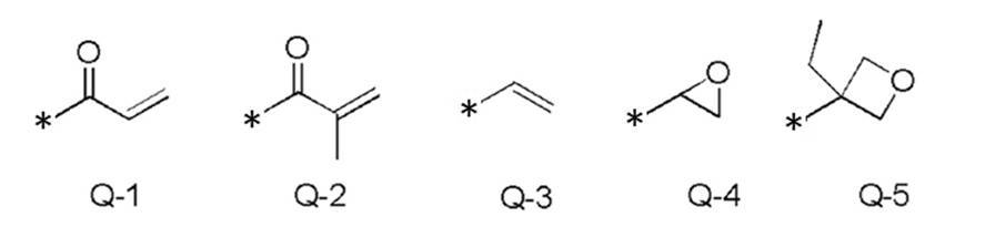
式(I)中の、フェニレン基は1,4-フェニレン基であることが好ましい。
フェニレン基およびトランス-1,4-シクロヘキシレン基について「置換基を有していてもよい」というときの置換基は、特に限定されず、例えば、アルキル基、シクロアルキル基、アルコキシ基、アルキルエーテル基、アミド基、アミノ基、およびハロゲン原子ならびに、上記の置換基を2つ以上組み合わせて構成される基からなる群から選択される置換基が挙げられる。また、置換基の例としては、後述の-C(=O)-X3-Sp3-Q3で表される置換基が挙げられる。フェニレン基およびトランス-1,4-シクロヘキシレン基は、置換基を1~4個有していてもよい。2個以上の置換基を有するとき、2個以上の置換基は互いに同一であっても異なっていてもよい。
フェニレン基およびトランス-1,4-シクロヘキシレン基について「置換基を有していてもよい」というときの置換基は、特に限定されず、例えば、アルキル基、シクロアルキル基、アルコキシ基、アルキルエーテル基、アミド基、アミノ基、およびハロゲン原子ならびに、上記の置換基を2つ以上組み合わせて構成される基からなる群から選択される置換基が挙げられる。また、置換基の例としては、後述の-C(=O)-X3-Sp3-Q3で表される置換基が挙げられる。フェニレン基およびトランス-1,4-シクロヘキシレン基は、置換基を1~4個有していてもよい。2個以上の置換基を有するとき、2個以上の置換基は互いに同一であっても異なっていてもよい。
本明細書において、アルキル基は直鎖状または分岐鎖状のいずれでもよい。アルキル基の炭素数は1~30が好ましく、1~10がより好ましく、1~6が特に好ましい。アルキル基の例としては、例えば、メチル基、エチル基、n-プロピル基、イソプロピル基、n-ブチル基、イソブチル基、sec-ブチル基、tert-ブチル基、n-ペンチル基、イソペンチル基、ネオペンチル基、1,1-ジメチルプロピル基、n-ヘキシル基、イソヘキシル基、直鎖状または分岐鎖状のヘプチル基、オクチル基、ノニル基、デシル基、ウンデシル基、またはドデシル基を挙げることができる。アルキル基に関する上記説明はアルキル基を含むアルコキシ基においても同様である。また、本明細書において、アルキレン基というときのアルキレン基の具体例としては、上記のアルキル基の例それぞれにおいて、任意の水素原子を1つ除いて得られる2価の基などが挙げられる。ハロゲン原子としては、フッ素原子、塩素原子、臭素原子、およびヨウ素原子が挙げられる。
本明細書において、シクロアルキル基の炭素数は、3~20が好ましく、5以上がより好ましく、また、10以下が好ましく、8以下がより好ましく、6以下がさらに好ましい。シクロアルキル基の例としては、シクロプロピル基、シクロブチル基、シクロペンチル基、シクロヘキシル基、シクロヘプチル基、シクロオクチル基を挙げることができる。
フェニレン基およびトランス-1,4-シクロヘキシレン基が有していてもよい置換基としては特に、アルキル基、およびアルコキシ基、-C(=O)-X3-Sp3-Q3からなる群から選択される置換基が好ましい。ここで、X3は単結合、-O-、-S-、もしくは-N(Sp4-Q4)-を示すか、または、Q3およびSp3と共に環構造を形成している窒素原子を示す。Sp3、Sp4はそれぞれ独立に、単結合、炭素数1から20の直鎖もしくは分岐のアルキレン基、および炭素数1から20の直鎖もしくは分岐のアルキレン基において1つまたは2つ以上の-CH2-が-O-、-S-、-NH-、-N(CH3)-、-C(=O)-、-OC(=O)-、または-C(=O)O-で置換された基からなる群から選択される連結基を示す。
Q3およびQ4はそれぞれ独立に、水素原子、シクロアルキル基、シクロアルキル基において1つもしくは2つ以上の-CH2-が-O-、-S-、-NH-、-N(CH3)-、-C(=O)-、-OC(=O)-、もしくは-C(=O)O-で置換された基、または式Q-1~式Q-5で表される基からなる群から選択されるいずれかの重合性基を示す。
シクロアルキル基において1つまたは2つ以上の-CH2-が-O-、-S-、-NH-、-N(CH3)-、-C(=O)-、-OC(=O)-、または-C(=O)O-で置換された基として、具体的には、テトラヒドロフラニル基、ピロリジニル基、イミダゾリジニル基、ピラゾリジニル基、ピペリジル基、ピペラジニル基、モルホルニル基、などが挙げられる。置換位置は特に限定されない。これらのうち、テトラヒドロフラニル基が好ましく、特に2-テトラヒドロフラニル基が好ましい。
式(I)において、Lは単結合、-CH2O-、-OCH2-、-(CH2)2OC(=O)-、-C(=O)O(CH2)2-、-C(=O)O-、-OC(=O)-、-OC(=O)O-、-CH=CH-C(=O)O-、-OC(=O)-CH=CH-、からなる群から選択される連結基を示す。Lは-C(=O)O-または-OC(=O)-であることが好ましい。m-1個のLは互いに同一でも異なっていてもよい。
Sp1、Sp2はそれぞれ独立に、単結合、炭素数1から20の直鎖もしくは分岐のアルキレン基、および炭素数1から20の直鎖もしくは分岐のアルキレン基において1つまたは2つ以上の-CH2-が-O-、-S-、-NH-、-N(CH3)-、-C(=O)-、-OC(=O)-、または-C(=O)O-で置換された基からなる群から選択される連結基を示す。Sp1およびSp2はそれぞれ独立に、両末端にそれぞれ-O-、-OC(=O)-、および-C(=O)O-からなる群から選択される連結基が結合した炭素数1から10の直鎖のアルキレン基、-OC(=O)-、-C(=O)O-、-O-、および炭素数1から10の直鎖のアルキレン基からなる群から選択される基を1または2以上組み合わせて構成される連結基であることが好ましく、両方の末端に-O-がそれぞれ結合した炭素数1から10の直鎖のアルキレン基であることが好ましい。
Q1およびQ2はそれぞれ独立に、水素原子、もしくは上記の式Q-1~式Q-5で表される基からなる群から選択される重合性基を示し、ただしQ1およびQ2のいずれか一方は重合性基を示す。
重合性基としては、アクリロイル基(式Q-1)またはメタクリロイル基(式Q-2)が好ましい。
重合性基としては、アクリロイル基(式Q-1)またはメタクリロイル基(式Q-2)が好ましい。
式(I)中、mは3~12の整数を示し、3~9の整数であることが好ましく、3~7の整数であることがより好ましく、3~5の整数であることがさらに好ましい。
式(I)で表される重合性化合物は、Aとして置換基を有していてもよいフェニレン基を少なくとも1つおよび置換基を有していてもよいトランス-1,4-シクロヘキシレン基を少なくとも1つ含むことが好ましい。式(I)で表される重合性化合物は、Aとして、置換基を有していてもよいトランス-1,4-シクロヘキシレン基を1~4個含むことが好ましく、1~3個含むことがより好ましく、2又は3個含むことがさらに好ましい。また、式(I)で表される重合性化合物は、Aとして、置換基を有していてもよいフェニレン基を1個以上含むことが好ましく、1~4個含むことがより好ましく、1~3個含むことがさらに好ましく、2個又は3個含むことが特に好ましい。
式(I)において、Aで表されるトランス-1,4-シクロヘキシレン基の数をmで割った数をmcとしたとき、0.1<mc<0.9であることが好ましく、0.3<mc<0.8であることがより好ましく、0.5<mc<0.7であることがさらに好ましい。液晶組成物が0.5<mc<0.7である式(I)で表される重合性化合物とともに、0.1<mc<0.3である式(I)で表される重合性化合物を含むことも好ましい。
式(I)で表される重合性化合物の例として具体的には、WO2016/047648の段落0051~0058に記載の化合物のほか、特開2013-112631号公報、特開2010-70543号公報、特許4725516号、国際公開WO2015/115390、WO2015/147243、WO2016/035873、特開2015-163596号公報、および特開2016-53149号公報に記載の化合物などを挙げることができる。
(キラル剤:光学活性化合物)
キラル剤はコレステリック液晶相の螺旋構造を誘起する機能を有する。キラル化合物は、化合物によって誘起する螺旋のセンスまたは螺旋ピッチが異なるため、目的に応じて選択すればよい。
キラル剤としては、特に制限はなく、公知の化合物を用いることができる。キラル剤の例としては、液晶デバイスハンドブック(第3章4-3項、TN、STN用カイラル剤、199頁、日本学術振興会第142委員会編、1989)、特開2003-287623号、特開2002-302487号、特開2002-80478号、特開2002-80851号、特開2010-181852号または特開2014-034581号の各公報に記載の化合物が挙げられる。
キラル剤は、一般に不斉炭素原子を含むが、不斉炭素原子を含まない軸性不斉化合物あるいは面性不斉化合物もキラル剤として用いることができる。軸性不斉化合物または面性不斉化合物の例には、ビナフチル、ヘリセン、パラシクロファンおよびこれらの誘導体が含まれる。キラル剤は、重合性基を有していてもよい。キラル剤と液晶化合物とがいずれも重合性基を有する場合は、重合性キラル剤と重合性液晶化合物との重合反応により、重合性液晶化合物から誘導される繰り返し単位と、キラル剤から誘導される繰り返し単位とを有するポリマーを形成することができる。この態様では、重合性キラル剤が有する重合性基は、重合性液晶化合物が有する重合性基と、同種の基であることが好ましい。従って、キラル剤の重合性基も、不飽和重合性基、エポキシ基またはアジリジニル基であることが好ましく、不飽和重合性基であることがさらに好ましく、エチレン性不飽和重合性基であることが特に好ましい。
また、キラル剤は、液晶化合物であってもよい。
また、キラル剤は、液晶化合物であってもよい。
キラル剤としては、イソソルビド誘導体、イソマンニド誘導体、またはビナフチル誘導体を好ましく用いることができる。イソソルビド誘導体としては、BASF社製のLC-756等の市販品を用いてもよい。
液晶組成物における、キラル剤の含有量は、重合性液晶化合物量の0.01モル%~200モル%が好ましく、1モル%~30モル%がより好ましい。
液晶組成物における、キラル剤の含有量は、重合性液晶化合物量の0.01モル%~200モル%が好ましく、1モル%~30モル%がより好ましい。
(重合開始剤)
液晶組成物は、重合開始剤を含有していることが好ましい。紫外線照射により重合反応を進行させる態様では、使用する重合開始剤は、紫外線照射によって重合反応を開始可能な光重合開始剤であることが好ましい。光重合開始剤の例には、α-カルボニル化合物(米国特許第2367661号、米国特許第2367670号の各明細書記載)、アシロインエーテル(米国特許第2448828号明細書記載)、α-炭化水素置換芳香族アシロイン化合物(米国特許第2722512号明細書記載)、多核キノン化合物(米国特許第3046127号、米国特許第2951758号の各明細書記載)、トリアリールイミダゾールダイマーとp-アミノフェニルケトンとの組み合わせ(米国特許第3549367号明細書記載)、アクリジンおよびフェナジン化合物(特開昭60-105667号公報、米国特許第4239850号明細書記載)、アシルフォスフィンオキシド化合物(特公昭63-40799号公報、特公平5-29234号公報、特開平10-95788号公報、特開平10-29997号公報、特開2001-233842号公報、特開2000-80068号公報、特開2006-342166号公報、特開2013-114249号公報、特開2014-137466号公報、特許4223071号公報、特開2010-262028号公報、特表2014-500852号公報記載)、オキシム化合物(特開2000-66385号公報、日本特許第4454067号明細書記載)、およびオキサジアゾール化合物(米国特許第4212970号明細書記載)等が挙げられる。例えば、特開2012-208494号公報の段落0500~0547の記載も参酌できる。
液晶組成物は、重合開始剤を含有していることが好ましい。紫外線照射により重合反応を進行させる態様では、使用する重合開始剤は、紫外線照射によって重合反応を開始可能な光重合開始剤であることが好ましい。光重合開始剤の例には、α-カルボニル化合物(米国特許第2367661号、米国特許第2367670号の各明細書記載)、アシロインエーテル(米国特許第2448828号明細書記載)、α-炭化水素置換芳香族アシロイン化合物(米国特許第2722512号明細書記載)、多核キノン化合物(米国特許第3046127号、米国特許第2951758号の各明細書記載)、トリアリールイミダゾールダイマーとp-アミノフェニルケトンとの組み合わせ(米国特許第3549367号明細書記載)、アクリジンおよびフェナジン化合物(特開昭60-105667号公報、米国特許第4239850号明細書記載)、アシルフォスフィンオキシド化合物(特公昭63-40799号公報、特公平5-29234号公報、特開平10-95788号公報、特開平10-29997号公報、特開2001-233842号公報、特開2000-80068号公報、特開2006-342166号公報、特開2013-114249号公報、特開2014-137466号公報、特許4223071号公報、特開2010-262028号公報、特表2014-500852号公報記載)、オキシム化合物(特開2000-66385号公報、日本特許第4454067号明細書記載)、およびオキサジアゾール化合物(米国特許第4212970号明細書記載)等が挙げられる。例えば、特開2012-208494号公報の段落0500~0547の記載も参酌できる。
重合開始剤としては、アシルフォスフィンオキシド化合物またはオキシム化合物を用いることも好ましい。
アシルフォスフィンオキシド化合物としては、例えば、市販品のBASFジャパン(株)製のIRGACURE810(化合物名:ビス(2,4,6-トリメチルベンゾイル)-フェニルフォスフィンオキサイド)を用いることができる。オキシム化合物としては、IRGACURE OXE01(BASF社製)、IRGACURE OXE02(BASF社製)、TR-PBG-304(常州強力電子新材料有限公司製)、アデカアークルズNCI-831、アデカアークルズNCI-930(ADEKA社製)、アデカアークルズNCI-831(ADEKA社製)等の市販品を用いることができる。
重合開始剤は、1種のみ用いてもよいし、2種以上を併用してもよい。
液晶組成物中の光重合開始剤の含有量は、重合性液晶化合物の含有量に対して0.1質量%~20質量%であることが好ましく、0.5質量%~5質量%であることがさらに好ましい。
(架橋剤)
液晶組成物は、硬化後の膜強度向上、耐久性向上のため、任意に架橋剤を含有していてもよい。架橋剤としては、紫外線、熱、湿気等で硬化するものが好適に使用できる。
架橋剤としては、特に制限はなく、目的に応じて適宜選択することができ、例えばトリメチロールプロパントリ(メタ)アクリレート、ペンタエリスリトールトリ(メタ)アクリレート等の多官能アクリレート化合物;グリシジル(メタ)アクリレート、エチレングリコールジグリシジルエーテル等のエポキシ化合物;2,2-ビスヒドロキシメチルブタノール-トリス[3-(1-アジリジニル)プロピオネート]、4,4-ビス(エチレンイミノカルボニルアミノ)ジフェニルメタン等のアジリジン化合物;ヘキサメチレンジイソシアネート、ビウレット型イソシアネート等のイソシアネート化合物;オキサゾリン基を側鎖に有するポリオキサゾリン化合物;ビニルトリメトキシシラン、N-(2-アミノエチル)3-アミノプロピルトリメトキシシラン等のアルコキシシラン化合物などが挙げられる。また、架橋剤の反応性に応じて公知の触媒を用いることができ、膜強度および耐久性向上に加えて生産性を向上させることができる。これらは、1種単独で使用してもよいし、2種以上を併用してもよい。
架橋剤の含有量は、3質量%~20質量%が好ましく、5質量%~15質量%がより好ましい。架橋剤の含有量を3質量%以上とすることにより、架橋密度向上の効果を得ることができ、架橋剤の含有量を20質量%以下とすることにより、コレステリック液晶層の安定性の低下を防止できる。
(配向制御剤)
液晶組成物中には、安定的にまたは迅速にプレーナー配向のコレステリック液晶層とするために寄与する配向制御剤を添加してもよい。配向制御剤の例としては特開2007-272185号公報の段落〔0018〕~〔0043〕等に記載のフッ素(メタ)アクリレート系ポリマー、特開2012-203237号公報の段落〔0031〕~〔0034〕等に記載の式(I)~(IV)で表される化合物などが挙げられる。
なお、配向制御剤としては1種を単独で用いてもよいし、2種以上を併用してもよい。
液晶組成物中には、安定的にまたは迅速にプレーナー配向のコレステリック液晶層とするために寄与する配向制御剤を添加してもよい。配向制御剤の例としては特開2007-272185号公報の段落〔0018〕~〔0043〕等に記載のフッ素(メタ)アクリレート系ポリマー、特開2012-203237号公報の段落〔0031〕~〔0034〕等に記載の式(I)~(IV)で表される化合物などが挙げられる。
なお、配向制御剤としては1種を単独で用いてもよいし、2種以上を併用してもよい。
液晶組成物中における、配向制御剤の添加量は、重合性液晶化合物の全質量に対して0.01質量%~10質量%が好ましく、0.01質量%~5質量%がより好ましく、0.02質量%~1質量%が特に好ましい。
(その他の添加剤)
その他、液晶組成物は、塗膜の表面張力を調整し厚みを均一にするための界面活性剤、および重合性モノマー等の種々の添加剤から選ばれる少なくとも1種を含有していてもよい。また、液晶組成物中には、必要に応じて、さらに重合禁止剤、酸化防止剤、紫外線吸収剤、光安定化剤、色材、金属酸化物微粒子等を、光学性能を低下させない範囲で添加することができる。
その他、液晶組成物は、塗膜の表面張力を調整し厚みを均一にするための界面活性剤、および重合性モノマー等の種々の添加剤から選ばれる少なくとも1種を含有していてもよい。また、液晶組成物中には、必要に応じて、さらに重合禁止剤、酸化防止剤、紫外線吸収剤、光安定化剤、色材、金属酸化物微粒子等を、光学性能を低下させない範囲で添加することができる。
コレステリック液晶層は、重合性液晶化合物および重合開始剤、更に必要に応じて添加されるキラル剤、界面活性剤等を溶媒に溶解させた液晶組成物を、支持体、配向層、または先に作製されたコレステリック液晶層等の上に塗布し、乾燥させて塗膜を得、この塗膜に活性光線を照射してコレステリック液晶性組成物を重合し、コレステリック規則性が固定化されたコレステリック液晶層を形成することができる。なお、複数のコレステリック液晶層からなる積層膜は、コレステリック液晶層の上記製造工程を繰り返し行うことにより形成することができる。
(溶媒)
液晶組成物の調製に使用する溶媒としては、特に制限はなく、目的に応じて適宜選択することができるが、有機溶媒が好ましく用いられる。
有機溶媒としては、特に制限はなく、目的に応じて適宜選択することができ、例えばケトン類、アルキルハライド類、アミド類、スルホキシド類、ヘテロ環化合物、炭化水素類、エステル類、エーテル類、などが挙げられる。これらは、1種単独で使用してもよいし、2種以上を併用してもよい。これらの中でも、環境への負荷を考慮した場合にはケトン類が特に好ましい。
液晶組成物の調製に使用する溶媒としては、特に制限はなく、目的に応じて適宜選択することができるが、有機溶媒が好ましく用いられる。
有機溶媒としては、特に制限はなく、目的に応じて適宜選択することができ、例えばケトン類、アルキルハライド類、アミド類、スルホキシド類、ヘテロ環化合物、炭化水素類、エステル類、エーテル類、などが挙げられる。これらは、1種単独で使用してもよいし、2種以上を併用してもよい。これらの中でも、環境への負荷を考慮した場合にはケトン類が特に好ましい。
(塗布、配向、重合)
支持体、配向層、下層となるコレステリック液晶層などへの液晶組成物の塗布方法は、特に制限はなく、目的に応じて適宜選択することができ、例えば、ワイヤーバーコーティング法、カーテンコーティング法、押し出しコーティング法、ダイレクトグラビアコーティング法、リバースグラビアコーティング法、ダイコーティング法、スピンコーティング法、ディップコーティング法、スプレーコーティング法、スライドコーティング法などが挙げられる。また、別途支持体上に塗設した液晶組成物を転写することによっても実施できる。塗布した液晶組成物を加熱することにより、液晶分子を配向させる。加熱温度は、200℃以下が好ましく、130℃以下がより好ましい。この配向処理により、重合性液晶化合物が、フィルム面に対して実質的に垂直な方向に螺旋軸を有するようにねじれ配向している光学薄膜が得られる。
支持体、配向層、下層となるコレステリック液晶層などへの液晶組成物の塗布方法は、特に制限はなく、目的に応じて適宜選択することができ、例えば、ワイヤーバーコーティング法、カーテンコーティング法、押し出しコーティング法、ダイレクトグラビアコーティング法、リバースグラビアコーティング法、ダイコーティング法、スピンコーティング法、ディップコーティング法、スプレーコーティング法、スライドコーティング法などが挙げられる。また、別途支持体上に塗設した液晶組成物を転写することによっても実施できる。塗布した液晶組成物を加熱することにより、液晶分子を配向させる。加熱温度は、200℃以下が好ましく、130℃以下がより好ましい。この配向処理により、重合性液晶化合物が、フィルム面に対して実質的に垂直な方向に螺旋軸を有するようにねじれ配向している光学薄膜が得られる。
配向させた液晶化合物をさらに重合させることにより、液晶組成物を硬化することができる。重合は、熱重合、光照射を利用する光重合のいずれでもよいが、光重合が好ましい。光照射は、紫外線を用いることが好ましい。照射エネルギーは、20mJ/cm2~50J/cm2が好ましく、100mJ/cm2~1,500mJ/cm2がより好ましい。
光重合反応を促進するため、加熱条件下または窒素雰囲気下で光照射を実施してもよい。照射紫外線波長は350nm~430nmが好ましい。重合反応率は安定性の観点から、高いほうが好ましく70%以上が好ましく、80%以上がより好ましい。重合反応率は、重合性の官能基の消費割合をIR吸収スペクトルを用いて測定することにより、決定することができる。
光重合反応を促進するため、加熱条件下または窒素雰囲気下で光照射を実施してもよい。照射紫外線波長は350nm~430nmが好ましい。重合反応率は安定性の観点から、高いほうが好ましく70%以上が好ましく、80%以上がより好ましい。重合反応率は、重合性の官能基の消費割合をIR吸収スペクトルを用いて測定することにより、決定することができる。
[λ/2位相差層]
λ/2位相差層を上記円偏光反射層と組み合わせて用いることにより、鮮明な投映像を表示することができる。λ/2位相差層と上記円偏光反射層とを組み合わせて作製した投映像表示部位は、例えば、λ/4位相差層と上記円偏光反射層とを組み合わせて用いた投映像表示部位と比較して、より高い輝度を与える。また二重像も防止できる。
λ/2位相差層を上記円偏光反射層と組み合わせて用いることにより、鮮明な投映像を表示することができる。λ/2位相差層と上記円偏光反射層とを組み合わせて作製した投映像表示部位は、例えば、λ/4位相差層と上記円偏光反射層とを組み合わせて用いた投映像表示部位と比較して、より高い輝度を与える。また二重像も防止できる。
λ/2位相差層の正面位相差は、可視光波長域の1/2の長さ、または「中心波長×n±中心波長の1/2(nは整数)」であればよい。特に円偏光反射層(例えばいずれかのコレステリック液晶)の反射波長、または光源の発光波長の中心波長の1/2の長さなどであればよい。例えば、190nm~390nmの範囲の位相差であればよく、200nm~350nmの範囲の位相差であることが好ましい。
λ/2位相差層としては、特に制限はなく、目的に応じて適宜選択することができるが、例えば、延伸されたポリカーボネートフィルム、延伸されたノルボルネン系ポリマーフィルム、炭酸ストロンチウムのような複屈折を有する無機粒子を含有して配向させた透明フィルム、支持体上に無機誘電体を斜め蒸着した薄膜、液晶化合物を一軸配向させて配向固定したフィルム、などが挙げられる。
λ/2位相差層としては、重合性液晶化合物を一軸配向させて配向固定したフィルムが好ましい。例えば、λ/2位相差層は、仮支持体、または配向層表面に重合性液晶化合物を含む液晶組成物を塗布し、そこで液晶組成物中の重合性液晶化合物を液晶状態においてネマチック配向に形成後、硬化によって固定化して、形成することができる。この場合のλ/2位相差層の形成は液晶組成物中にキラル剤を添加しない以外は、上記のコレステリック液晶層の形成と同様に行うことができる。ただし、液晶組成物の塗布後のネマチック配向の際、加熱温度は50℃~120℃が好ましく、60℃~100℃がより好ましい。
λ/2位相差層は、高分子液晶化合物を含む組成物を、仮支持体または配向層等の表面に塗布して液晶状態においてネマチック配向に形成後、冷却することによって当該配向を固定化して得られる層であってもよい。
λ/2位相差層の厚みは、0.2μm~300μmが好ましく、0.5μm~150μmがより好ましく、1.0μm~80μmがさらに好ましい。液晶組成物から形成されるλ/2位相差層の厚みは、特に限定はされないが、0.2μm~10μmが好ましく、0.5μm~5.0μmがより好ましく、1.0μm~2.0μmがさらに好ましい。
λ/2位相差層の遅相軸方向は、ヘッドアップディスプレイシステムとしての使用時の、投映像表示のための入射光の入射方向、およびコレステリック液晶層の螺旋のセンスに応じて決定することが好ましい。例えば、入射光が投映像表示部位の下(鉛直下)方向であって、円偏光反射層に対してλ/2位相差層側から(本明細書において「観察者側から」ということがある)入射する場合は、投映像表示部位の鉛直上方向に対し、λ/2位相差層の遅相軸が+40°~+65°、または-40°~-65°の範囲にあることが好ましい。また円偏光反射層におけるコレステリック液晶層の螺旋のセンスに応じて、以下のように遅相軸方向が設定されることが好ましい。上記センスが右の場合、(好ましくは、全てのコレステリック液晶層のセンスが右の場合、)投映像表示部位の鉛直上方向に対し、λ/2位相差層の遅相軸が観察者側から見て時計回りに40°~65°、好ましくは45°~60°の範囲にあることが好ましい。上記センスが左の場合(好ましくは、全てのコレステリック液晶層のセンスが左の場合)、投映像表示部位の鉛直上方向に対し、λ/2位相差層の遅相軸が観察者側から見て反時計回りに40°~65°、好ましくは45°~60°の範囲にあることが好ましい。
[第2の位相差層]
本発明のウインドシールドガラスにおける投映像表示部位は、λ/2位相差層に加えて第2の位相差層を含んでいてもよい。第2の位相差層は、λ/2位相差層、円偏光反射層、および第2の位相差層がこの順になるように設ければよい。特に、観察者側からλ/2位相差層、円偏光反射層、および第2の位相差層がこの順になるように設ければよい。本明細書においては、第2の位相差層がλ/2位相差を有する場合も、より観察者側に近いλ/2位相差層とは区別して第2の位相差層という。上記の位置に第2の位相差層を含むことによって、二重像をさらに防止することができる。特に、p偏光を入射させて投映像を形成する場合の二重像をさらに防止することができる。その効果は、円偏光反射層におけるコレステリック液晶層の形成に低Δn重合性液晶化合物を用いた場合により顕著である。
第2の位相差層の利用により二重像をさらに防止することができる理由は、円偏光反射層に含まれるコレステリック液晶層の選択反射帯域にない波長の光がコレステリック液晶層で偏光変換してウインドシールドガラスの裏面で反射されることに基づく二重像を防止できるためと推定される。
第2の位相差層の位相差は、波長550nmにおいて160nm~460nmの範囲、好ましくは240nm~420nmの範囲で適宜調整すればよい。
第2の位相差層の材料および厚み等は、λ/2位相差層と同様の範囲で選択することができる。
第2の位相差層の材料および厚み等は、λ/2位相差層と同様の範囲で選択することができる。
第2の位相差層の遅相軸方向は、投映像表示のための入射光の入射方向、およびコレステリック液晶層の螺旋のセンスに応じて決定することが好ましい。例えば、波長550nmにおいて160nm~400nmの範囲の位相差の第2の位相差層を投映像表示部位の鉛直上方向に対し、遅相軸が+10°~+35°、または-10°~-35°の範囲となるようにすることが好ましい。または、波長550nmにおいて200nm~400nmの範囲の位相差の第2の位相差層を投映像表示部位の鉛直上方向に対し、遅相軸が+100°~+140°、または-100°~-140°の範囲となるようにすることが好ましい。
[他の層]
投映像表示部位、またはハーフミラーフィルムはコレステリック液晶層、λ/2位相差層、および第2の位相差層以外の他の層を含んでいてもよい。他の層はいずれも可視光領域で透明であることが好ましい。本明細書において可視光領域で透明であるとは、可視光の透過率が70%以上であることをいう。
また、他の層はいずれも低複屈折性であることが好ましい。本明細書において低複屈折性であるとは、本発明のウインドシールドガラスの投映像表示部位が反射を示す波長域において、正面位相差が10nm以下であることを意味し、上記正面位相差は5nm以下であることが好ましい。さらに、他の層はいずれもコレステリック液晶層の平均屈折率(面内平均屈折率)との屈折率の差が小さいことが好ましい。他の層としては支持体、配向層、接着層などが挙げられる。
(支持体)
支持体は、コレステリック液晶層またはλ/2位相差層の形成の際に基板となることができる。
支持体は、コレステリック液晶層またはλ/2位相差層の形成の際に基板となることができる。
支持体は特に限定されない。コレステリック液晶層またはλ/2位相差層の形成のために用いられる支持体は、コレステリック液晶層形成後に剥離される仮支持体であって、完成したハーフミラーフィルムまたはウインドシールドガラスにおいては含まれていなくてもよい。支持体としてはポリエチレンテレフタレート(PET)などのポリエステル、ポリカーボネート、アクリル樹脂、エポキシ樹脂、ポリウレタン、ポリアミド、ポリオレフィン、セルロース誘導体、シリコーンなどのプラスチックフィルムが挙げられる。仮支持体としては、上記のプラスチックフィルムのほか、ガラスを用いてもよい。
支持体の厚みとしては、5.0μm~1000μm程度であればよく、10μm~250μmが好ましく、15μm~90μmがより好ましい。
支持体の厚みとしては、5.0μm~1000μm程度であればよく、10μm~250μmが好ましく、15μm~90μmがより好ましい。
(配向層)
投映像表示部位は、コレステリック液晶層またはλ/2位相差層の形成の際に液晶組成物が塗布される下層として、配向層を含んでいてもよい。
配向層は、ポリマーなどの有機化合物(ポリイミド、ポリビニルアルコール、ポリエステル、ポリアリレート、ポリアミドイミド、ポリエーテルイミド、ポリアミド、変性ポリアミドなどの樹脂)のラビング処理、無機化合物の斜方蒸着、マイクログルーブを有する層の形成、またはラングミュア・ブロジェット法(LB膜)を用いた有機化合物(例えば、ω-トリコサン酸、ジオクタデシルメチルアンモニウムクロライド、ステアリル酸メチル)の累積のような手段で、設けることができる。更に、電場の付与、磁場の付与または光照射により、配向機能が生じる配向層を用いてもよい。
特にポリマーからなる配向層はラビング処理を行ったうえで、ラビング処理面に液晶組成物を塗布することが好ましい。ラビング処理は、ポリマー層の表面を、紙、布で一定方向に、擦ることにより実施することができる。
配向層を設けずに支持体表面、または支持体をラビング処理した表面に、液晶組成物を塗布してもよい。
仮支持体を用いて液晶層を形成する場合は、配向層は仮支持体とともに剥離されて投映像表示部位を構成する層とはならなくてもよい。
配向層の厚みは、0.01~5.0μmであることが好ましく、0.05~2.0μmであることがさらに好ましい。
(接着層)
接着層は、例えばコレステリック液晶層間、円偏光反射層とλ/2位相差層との間、円偏光反射層と第2の位相差層との間、コレステリック液晶層と支持体との間に設けられていてもよい。また、円偏光反射層と中間膜シートとの間、λ/2位相差層と中間膜シートとの間等に設けられていてもよい。
接着層は、例えばコレステリック液晶層間、円偏光反射層とλ/2位相差層との間、円偏光反射層と第2の位相差層との間、コレステリック液晶層と支持体との間に設けられていてもよい。また、円偏光反射層と中間膜シートとの間、λ/2位相差層と中間膜シートとの間等に設けられていてもよい。
接着層は接着剤から形成されるものであればよい。
接着剤としては硬化方式の観点からホットメルトタイプ、熱硬化タイプ、光硬化タイプ、反応硬化タイプ、硬化の不要な感圧接着タイプがあり、それぞれ素材としてアクリレート系、ウレタン系、ウレタンアクリレート系、エポキシ系、エポキシアクリレート系、ポリオレフィン系、変性オレフィン系、ポリプロピレン系、エチレンビニルアルコール系、塩化ビニル系、クロロプレンゴム系、シアノアクリレート系、ポリアミド系、ポリイミド系、ポリスチレン系、ポリビニルブチラール系などの化合物を使用することができる。作業性、生産性の観点から、硬化方式として光硬化タイプが好ましく、光学的な透明性、耐熱性の観点から、素材はアクリレート系、ウレタンアクリレート系、エポキシアクリレート系などを使用することが好ましい。
接着剤としては硬化方式の観点からホットメルトタイプ、熱硬化タイプ、光硬化タイプ、反応硬化タイプ、硬化の不要な感圧接着タイプがあり、それぞれ素材としてアクリレート系、ウレタン系、ウレタンアクリレート系、エポキシ系、エポキシアクリレート系、ポリオレフィン系、変性オレフィン系、ポリプロピレン系、エチレンビニルアルコール系、塩化ビニル系、クロロプレンゴム系、シアノアクリレート系、ポリアミド系、ポリイミド系、ポリスチレン系、ポリビニルブチラール系などの化合物を使用することができる。作業性、生産性の観点から、硬化方式として光硬化タイプが好ましく、光学的な透明性、耐熱性の観点から、素材はアクリレート系、ウレタンアクリレート系、エポキシアクリレート系などを使用することが好ましい。
接着層は、高透明性接着剤転写テープ(OCAテープ)を用いて形成されたものであってもよい。高透明性接着剤転写テープとしては、画像表示装置用の市販品、特に画像表示装置の画像表示部表面用の市販品を用いればよい。市販品の例としては、パナック株式会社製の粘着シート(PD-S1など)、日栄化工株式会社のMHMシリーズの粘着シートなどが挙げられる。
接着層の厚みは、0.5~10μmであることが好ましく、1.0~5.0μmであることがより好ましい。また、OCAテープを用いて形成された接着層の厚みは、10μm~50μmであってもよく、15μm~30μmが好ましい。投映像表示部位の色ムラ等を軽減するため均一な厚みで設けられることが好ましい。
接着層の厚みは、0.5~10μmであることが好ましく、1.0~5.0μmであることがより好ましい。また、OCAテープを用いて形成された接着層の厚みは、10μm~50μmであってもよく、15μm~30μmが好ましい。投映像表示部位の色ムラ等を軽減するため均一な厚みで設けられることが好ましい。
[円偏光反射層に対して視認側にある層]
一般的に、投映像表示用部材において、投映光を反射する層からの反射光に基づく像と、投映像表示用部材の光入射側から見て手前の面または裏側面からの反射光に基づく像が重なることによって二重像(または多重像)の問題が生じている。本発明のウインドシールドガラスにおいては、円偏光反射層中のコレステリック液晶層を透過する光は上記コレステリック液晶層を反射する円偏光と逆のセンスの円偏光となっており、裏側面からの反射光は、円偏光反射層より裏側面側にある層が低複屈折性である場合は、通常上記コレステリック液晶層に反射される円偏光が大部分となるため顕著な二重像を生じさせにくい。特に投映光として偏光を利用することにより投映光の大部分が円偏光反射層で反射されるように構成できる。一方で、手前の面からの反射光は顕著な二重像を生じさせ得る。特にコレステリック液晶層の重心からウインドシールドガラスの光入射側から見て手前の面までの距離が一定値以上であると二重像が顕著になり得る。具体的には、本発明のウインドシールドガラスの構造において、円偏光反射層よりλ/2位相差層側にある層の厚みの総計(円偏光反射層の厚みを含まず、λ/2位相差層の厚みを含む)、すなわち、円偏光反射層のλ/2位相差層側の最外面から、円偏光反射層に対してλ/2位相差層側のウインドシールドガラスの最外面までの距離は、二重像の低減の観点で、2.0mm以下が好ましく、1.0mm以下が更に好ましく、0.5mm以下が特に好ましい。円偏光反射層より視認側にある層としては、λ/2位相差層のほか、支持体、中間膜シート、第2のガラス板などが挙げられる。
しかし、本発明のウインドシールドガラスは後述のようにp偏光を利用した投映像表示において、円偏光反射層より視認側にある層の厚みの総計が上記のようである場合でも、顕著な二重像なしに投映像を視認することができる。
[合わせガラス]
ウインドシールドガラスは、合わせガラスの構成を有していてもよい。すなわち、2枚のガラス板が中間層を介して接着している構造を有することが好ましい。本明細書においては、ウインドシールドガラスにおいて、観察者側からより遠い位置にあるガラス板を第一のガラス板といい、より近い位置にあるガラス板を第二のガラス板ということがある。
ガラス板としては、ウインドシールドガラスに一般的に用いられるガラス板を利用することができる。ガラス板の厚みについては特に制限はないが、0.5mm~5.0mm程度であればよく、1.0mm~3.0mmが好ましく、2.0~2.3mmがより好ましい。
ウインドシールドガラスは、合わせガラスの構成を有していてもよい。すなわち、2枚のガラス板が中間層を介して接着している構造を有することが好ましい。本明細書においては、ウインドシールドガラスにおいて、観察者側からより遠い位置にあるガラス板を第一のガラス板といい、より近い位置にあるガラス板を第二のガラス板ということがある。
ガラス板としては、ウインドシールドガラスに一般的に用いられるガラス板を利用することができる。ガラス板の厚みについては特に制限はないが、0.5mm~5.0mm程度であればよく、1.0mm~3.0mmが好ましく、2.0~2.3mmがより好ましい。
合わせガラスの構成を有するウインドシールドガラスは、公知の合わせガラス作製方法を用いて製造することができる。一般的には、合わせガラス用の中間膜シートを2枚のガラス板に挟んだ後、加熱処理と加圧処理(ゴムローラーを用いた処理等)とを数回繰り返し、最後にオートクレーブ等を利用して加圧条件下での加熱処理を行う方法により製造することができる。
上記の円偏光反射層およびλ/2位相差層を含むハーフミラーフィルムを中間層に含む合わせガラスの構成を有するウインドシールドガラスは、ハーフミラーフィルムをガラス板表面に形成したあと通常の合わせガラス作製工程を経て形成されていてもよく、上記ハーフミラーフィルムを含む合わせガラス用積層中間膜シートを中間膜シートとして用いて、上記の加熱処理と加圧処理とが行われて形成されていてもよい。ハーフミラーフィルムをガラス板表面に形成する場合、ハーフミラーフィルムを形成するガラス板は、第一のガラス板であってもよく第二のガラス板であってもよい。このとき、ハーフミラーフィルムは例えばガラス板に接着剤で貼合されていればよい。
(中間膜シート)
上記ハーフミラーフィルムを含まない中間膜シートを用いる場合の中間膜シートとしては、公知のいずれの中間膜シートを用いてもよい。たとえば、ポリビニルブチラール(PVB)、エチレン-酢酸ビニル共重合体および塩素含有樹脂の群から選ばれる樹脂を含む樹脂膜を用いることができる。上記樹脂は、中間膜シートの主成分であることが好ましい。なお、主成分であるとは、中間膜シートの50質量%以上の割合を占める成分のことをいう。
上記ハーフミラーフィルムを含まない中間膜シートを用いる場合の中間膜シートとしては、公知のいずれの中間膜シートを用いてもよい。たとえば、ポリビニルブチラール(PVB)、エチレン-酢酸ビニル共重合体および塩素含有樹脂の群から選ばれる樹脂を含む樹脂膜を用いることができる。上記樹脂は、中間膜シートの主成分であることが好ましい。なお、主成分であるとは、中間膜シートの50質量%以上の割合を占める成分のことをいう。
上記の樹脂のうち、ポリビニルブチラールまたはエチレン-酢酸ビニル共重合体であることが好ましく、ポリビニルブチラールがより好ましい。樹脂は、合成樹脂であることが好ましい。
ポリビニルブチラールは、ポリビニルアルコールをブチルアルデヒドによりアセタール化して得ることができる。上記ポリビニルブチラールのアセタール化度の好ましい下限は40%、好ましい上限は85%であり、より好ましい下限は60%、より好ましい上限は75%である。
ポリビニルブチラールは、ポリビニルアルコールをブチルアルデヒドによりアセタール化して得ることができる。上記ポリビニルブチラールのアセタール化度の好ましい下限は40%、好ましい上限は85%であり、より好ましい下限は60%、より好ましい上限は75%である。
ポリビニルアルコールは、通常、ポリ酢酸ビニルを鹸化することにより得られ、鹸化度80~99.8モル%のポリビニルアルコールが一般的に用いられる。
また、上記ポリビニルアルコールの重合度の好ましい下限は200、好ましい上限は3000である。ポリビニルアルコールの重合度が200以上であると、得られる合わせガラスの耐貫通性が低下しにくく、3000以下であると、樹脂膜の成形性がよく、しかも樹脂膜の剛性が大きくなり過ぎず、加工性が良好である。より好ましい下限は500、より好ましい上限は2000である。
また、上記ポリビニルアルコールの重合度の好ましい下限は200、好ましい上限は3000である。ポリビニルアルコールの重合度が200以上であると、得られる合わせガラスの耐貫通性が低下しにくく、3000以下であると、樹脂膜の成形性がよく、しかも樹脂膜の剛性が大きくなり過ぎず、加工性が良好である。より好ましい下限は500、より好ましい上限は2000である。
(円偏光反射層およびλ/2位相差層を含む中間膜シート)
円偏光反射層およびλ/2位相差層を含む合わせガラス用積層中間膜シートは、上記ハーフミラーフィルムを上記中間膜シートの表面に貼合して形成することができる。または、上記ハーフミラーフィルムを2枚の上記中間膜シートに挟んで形成することもできる。2枚の中間膜シートは同一であってもよく異なっていてもよいが、同一であることが好ましい。
ハーフミラーフィルムと中間膜シートとの貼合には、公知の貼合方法を用いることができるが、ラミネート処理を用いることが好ましい。積層体と中間膜シートとが加工後に剥離してしまわないように、ラミネート処理を実施する場合には、ある程度の加熱および加圧条件下にて実施することが好ましい。
ラミネートを安定的に行なうには、中間膜シートの接着する側の膜面温度が50~130℃であることが好ましく、70~100℃であることがより好ましい。
ラミネート時には加圧することが好ましい。加圧条件は、2.0kg/cm2未満(196kPa未満)であることが好ましく、0.5~1.8kg/cm2(49~176kPa)の範囲であることがより好ましく、0.5~1.5kg/cm2(49~147kPa)の範囲であることがさらに好ましい。
また、支持体を含むハーフミラーフィルムにおいては、ラミネートと同時に、又はその直後、もしくはその直前に、支持体を剥離してもよい。即ち、ラミネート後に得られる積層中間膜シートには、支持体が無くてもよい。
合わせガラス用積層中間膜シートの製造方法の一例は、
(1)第1の中間膜シートの表面にハーフミラーフィルムを貼合して第1の積層体を得る第1の工程、および、
(2)第1の積層体中のハーフミラーフィルムの第1の中間膜シートが貼合されている面とは反対の面に、第2の中間膜シートを貼合する第2の工程、を含む。
第1の工程において、ハーフミラーフィルムと第1の中間膜シートとを貼合するとともに、支持体を剥離し、第2の工程において、第2の中間膜シートを、支持体を剥離した面に貼合する、合わせガラス用積層中間膜シートの製造方法により、支持体を含まない、合わせガラス用積層中間膜シートを製造することができ、この合わせガラス用積層中間膜シートを用いることで、支持体を含まない合わせガラスを容易に作製することができる。破損等無く、安定的に支持体を剥離するためには、ハーフミラーフィルムから支持体を剥離する際の基板の温度が40℃以上であることが好ましく、40~60℃であることがより好ましい。
<ヘッドアップディスプレイシステム>
本発明のウインドシールドガラスはヘッドアップディスプレイシステムの構成部材として用いることができる。ヘッドアップディスプレイシステムはプロジェクターを含む。
本発明のウインドシールドガラスはヘッドアップディスプレイシステムの構成部材として用いることができる。ヘッドアップディスプレイシステムはプロジェクターを含む。
[プロジェクター]
本明細書において、「プロジェクター」は「光または画像を投映する装置」であり、「描画した画像を投射する装置」を含む。本発明のヘッドアップディスプレイシステムにおいて、プロジェクターは、ウインドシールドガラス中の投映像表示部位に、投映像表示部位の法線に対し45°~70°の斜め入射角度で入射できるように配置されていればよい。
ヘッドアップディスプレイシステムにおいて、プロジェクターは、描画デバイスを含み、小型の中間像スクリーンに描画された画像(実像)をコンバイナにより虚像として反射表示するものが好ましい。
本明細書において、「プロジェクター」は「光または画像を投映する装置」であり、「描画した画像を投射する装置」を含む。本発明のヘッドアップディスプレイシステムにおいて、プロジェクターは、ウインドシールドガラス中の投映像表示部位に、投映像表示部位の法線に対し45°~70°の斜め入射角度で入射できるように配置されていればよい。
ヘッドアップディスプレイシステムにおいて、プロジェクターは、描画デバイスを含み、小型の中間像スクリーンに描画された画像(実像)をコンバイナにより虚像として反射表示するものが好ましい。
(描画デバイス)
描画デバイスはそれ自体が画像を表示するデバイスであってもよく、画像を描画できる光を発するデバイスであってもよい。描画デバイスでは、光源からの光が、光変調器、レーザー輝度変調手段、または描画のための光偏向手段などの描画方式で調整されていればよい。本明細書において、描画デバイスは光源を含み、さらに、描画方式に応じて光変調器、レーザー輝度変調手段、または描画のための光偏向手段などを含むデバイスを意味する。
描画デバイスはそれ自体が画像を表示するデバイスであってもよく、画像を描画できる光を発するデバイスであってもよい。描画デバイスでは、光源からの光が、光変調器、レーザー輝度変調手段、または描画のための光偏向手段などの描画方式で調整されていればよい。本明細書において、描画デバイスは光源を含み、さらに、描画方式に応じて光変調器、レーザー輝度変調手段、または描画のための光偏向手段などを含むデバイスを意味する。
(光源)
光源は特に限定されず、LED(発光ダイオード、有機発光ダイオード(OLED)を含む)、放電管、およびレーザー光源などを用いることができる。これらのうち、LEDおよび放電管が好ましい。直線偏光を出射する描画デバイスの光源に適しているからである。これらのうち、特にLEDが好ましい。LEDは発光波長が可視光領域において連続的でないため、後述するように特定波長域で選択反射を示すコレステリック液晶層が用いられているコンバイナとの組み合わせに適しているためである。
光源は特に限定されず、LED(発光ダイオード、有機発光ダイオード(OLED)を含む)、放電管、およびレーザー光源などを用いることができる。これらのうち、LEDおよび放電管が好ましい。直線偏光を出射する描画デバイスの光源に適しているからである。これらのうち、特にLEDが好ましい。LEDは発光波長が可視光領域において連続的でないため、後述するように特定波長域で選択反射を示すコレステリック液晶層が用いられているコンバイナとの組み合わせに適しているためである。
(描画方式)
描画方式としては、使用する光源や用途に応じて選択することができ、特に限定されない。
描画方式の例としては、蛍光表示管、液晶を利用するLCD(Liquid Crystal Display)方式およびLCOS(Liquid Crystal on Silicon)方式、DLP(登録商標)(Digital Light Processing)方式、レーザーを利用する走査方式などが挙げられる。描画方式は光源と一体となった蛍光表示管を用いた方式であってもよい。
描画方式としては、使用する光源や用途に応じて選択することができ、特に限定されない。
描画方式の例としては、蛍光表示管、液晶を利用するLCD(Liquid Crystal Display)方式およびLCOS(Liquid Crystal on Silicon)方式、DLP(登録商標)(Digital Light Processing)方式、レーザーを利用する走査方式などが挙げられる。描画方式は光源と一体となった蛍光表示管を用いた方式であってもよい。
LCD方式およびLCOS方式では、各色の光が光変調器で変調、合波され、投射レンズから光が出射する。
DLP方式は、DMD(Digital Micromirror Device)を用いた表示システムであり、画素数分のマイクロミラーを配置して描画され投射レンズから光が出射する。
走査方式は光線をスクリーン上で走査させ、目の残像を利用して造影する方式であり、例えば、特開平7-270711号公報、特開2013-228674号公報の記載が参照できる。レーザーを利用する走査方式では、輝度変調された各色(例えば、赤色光、緑色光、青色光)のレーザー光が合波光学系または集光レンズなどで1本の光線に束ねられ、光線が光偏向手段により走査されて後述する中間像スクリーンに描画されていればよい。
走査方式において、各色(例えば赤色光、緑色光、青色光)のレーザー光の輝度変調は光源の強度変化として直接行ってもよく、外部変調器により行ってもよい。光偏向手段としては、ガルバノミラー、ガルバノミラーとポリゴンミラーとの組み合わせ、またはMEMS(微小電子機械システム)が挙げられ、このうちMEMSが好ましい。走査方法としては、ランダムスキャン方式、およびラスタースキャン方式等が挙げられるが、ラスタースキャン方式を用いることが好ましい。ラスタースキャン方式において、レーザー光は、例えば、水平方向は共振周波数で、垂直方向はのこぎり波で駆動されることができる。走査方式は投射レンズが不要であるため、装置の小型化が容易である。
描画デバイスからの出射光は、直線偏光であっても自然光(非偏光)であってもよい。本発明のヘッドアップディスプレイシステムに含まれる描画デバイスからの出射光は、直線偏光であることが好ましい。描画方式がLCDまたはLCOSである描画デバイスおよびレーザー光源を用いた描画デバイスは、本質的には出射光が直線偏光となる。出射光が直線偏光である描画デバイスであって出射光が複数の波長(色)の光を含むものである場合は、複数の光の偏光の偏光方向(透過軸方向)は同一であるかまたは互いに直交していることが好ましい。市販の描画デバイスは、出射光の赤、緑、青の光の波長域での偏光方向が均一ではないものがあることが知られている(特開2000-221449号公報参照)。具体的には、緑色光の偏光方向が赤色光の偏光方向および青色光の偏光方向と直交している例が知られている。
(中間像スクリーン)
上記のように、描画デバイスは中間像スクリーンを使用するものであってもよい。本明細書において、「中間像スクリーン」は、画像が描画されるスクリーンである。すなわち、描画デバイスを出射した光がまだ画像として視認できるものではない場合などにおいて、この光によって描画デバイスは中間像スクリーンに視認可能な画像を形成する。中間像スクリーンにおいて描画された画像は中間像スクリーンを透過する光によりコンバイナに投映されていてもよく、中間像スクリーンを反射してコンバイナに投映されていてもよい。
上記のように、描画デバイスは中間像スクリーンを使用するものであってもよい。本明細書において、「中間像スクリーン」は、画像が描画されるスクリーンである。すなわち、描画デバイスを出射した光がまだ画像として視認できるものではない場合などにおいて、この光によって描画デバイスは中間像スクリーンに視認可能な画像を形成する。中間像スクリーンにおいて描画された画像は中間像スクリーンを透過する光によりコンバイナに投映されていてもよく、中間像スクリーンを反射してコンバイナに投映されていてもよい。
中間像スクリーンの例としては、散乱膜、マイクロレンズアレイ、リアプロジェクション用のスクリーンなどが挙げられる。中間像スクリーンとしてプラスチック材料を用いる場合などにおいて、中間像スクリーンが複屈折性を有すると、中間像スクリーンに入射した偏光の偏光面や光強度が乱され、コンバイナにおいて、色ムラ等が生じやすくなるが、所定の位相差を有する位相差膜を用いることにより、この色ムラの問題が低減できる。
中間像スクリーンとしては、入射光線を広げて透過させる機能を有するものが好ましい。投映像拡大表示が可能となるからである。このような中間像スクリーンとしては、例えばマイクロレンズアレイで構成されるスクリーンが挙げられる。ヘッドアップディスプレイで用いられるマイクロアレイレンズについては、例えば、特開2012-226303号公報、特開2010-145745号公報、および特表2007-523369号公報に記載がある。
プロジェクターは描画デバイスで形成された投映光の光路を調整する反射鏡などを含んでいてもよい。
中間像スクリーンとしては、入射光線を広げて透過させる機能を有するものが好ましい。投映像拡大表示が可能となるからである。このような中間像スクリーンとしては、例えばマイクロレンズアレイで構成されるスクリーンが挙げられる。ヘッドアップディスプレイで用いられるマイクロアレイレンズについては、例えば、特開2012-226303号公報、特開2010-145745号公報、および特表2007-523369号公報に記載がある。
プロジェクターは描画デバイスで形成された投映光の光路を調整する反射鏡などを含んでいてもよい。
ウインドシールドガラスを投映像表示用部材として用いたヘッドアップディスプレイシステムについては、特開平2-141720号公報、特開平10-96874号公報、特開2003-98470号公報、米国特許第5013134号明細書、特表2006-512622号公報などを参照することができる。
本発明のウインドシールドガラスは、特に、発光波長が可視光領域において連続的でないレーザーやLED、OLEDなどを光源に用いたプロジェクターと組み合わせて用いるヘッドアップディスプレイシステムに有用である。各発光波長に合わせて、コレステリック液晶層の選択反射の中心波長を調整できるからである。また、LCD(液晶表示装置)などの表示光が偏光しているディスプレイの投映に用いることもできる。
[投映光(入射光)]
入射光は、円偏光反射層に対してλ/2位相差層側から入射させ、λ/2位相差層を経由して円偏光反射層に入射させればよい。すなわち、円偏光反射層に対してλ/2位相差層を投映光の入射側に配置すればよい。また、入射光は、投映像表示部位の法線に対し45°~70°の斜め入射角度で入射させることが好ましい。屈折率1.51程度のガラスと屈折率1の空気との界面のブリュースター角は約56°であり、上記の角度の範囲でp偏光を入射させることにより、投映像表示のための入射光の円偏光反射層に対してλ/2位相差層表面からの反射光が少なく、二重像の影響が小さい画像表示が可能である。上記角度は50°~65°であることも好ましい。このとき、投映像の観察を投映光の入射側において、λ/2位相差層の法線に対し、入射光とは反対側で45°~70°、好ましくは50°~65°の角度で行うことができる構成であればよい。
入射光は、円偏光反射層に対してλ/2位相差層側から入射させ、λ/2位相差層を経由して円偏光反射層に入射させればよい。すなわち、円偏光反射層に対してλ/2位相差層を投映光の入射側に配置すればよい。また、入射光は、投映像表示部位の法線に対し45°~70°の斜め入射角度で入射させることが好ましい。屈折率1.51程度のガラスと屈折率1の空気との界面のブリュースター角は約56°であり、上記の角度の範囲でp偏光を入射させることにより、投映像表示のための入射光の円偏光反射層に対してλ/2位相差層表面からの反射光が少なく、二重像の影響が小さい画像表示が可能である。上記角度は50°~65°であることも好ましい。このとき、投映像の観察を投映光の入射側において、λ/2位相差層の法線に対し、入射光とは反対側で45°~70°、好ましくは50°~65°の角度で行うことができる構成であればよい。
入射光は、ウインドシールドガラスの上下左右等、いずれの方向から入射してもよく、観察者の方向と対応させて、決定すればよい。例えば使用時の下方向から上記のような斜め入射角度で入射していればよい。
また、ウインドシールドガラス中のλ/2位相差層の遅相軸は、入射p偏光の振動方向(入射光の入射面)に対し、40°~65°の角度をなしていることが好ましく、45°~60°の角度をなしていることがより好ましい。
また、ウインドシールドガラス中のλ/2位相差層の遅相軸は、入射p偏光の振動方向(入射光の入射面)に対し、40°~65°の角度をなしていることが好ましく、45°~60°の角度をなしていることがより好ましい。
上述のように、ヘッドアップディスプレイにおける投映像表示の際の投映光は入射面に平行な方向に振動するp偏光であることが好ましい。プロジェクターの出射光が直線偏光ではない場合は、直線偏光フィルムをプロジェクターの出射光側に配して用いることによりp偏光としていてもよく、プロジェクターからウインドシールドガラスまでの光路でp偏光とされていてもよい。上述のように、出射光の赤、緑、青の光の波長域での偏光方向が均一ではないプロジェクターについては、波長選択的に偏光方向を調節し、全ての色の波長域でp偏光として入射させることが好ましい。
ヘッドアップディスプレイシステムは、虚像結像位置を可変とする投映システムであってもよい。このような投映システムについては、例えば特開2009-150947号公報に記載がある。虚像結像位置を可変とすることにより、運転者はより快適に利便性高く虚像を視認することができる。虚像結像位置は、車両の運転者から虚像を視認できる位置であり、例えば、通常運転者から見てウインドシールドガラスの先、1000mm以上離れた位置である。ここで、上述の特表2011-505330号公報に記載のようにガラスが投映像表示部位において不均一(楔形)であると、虚像結像位置を変化させたときに、その楔形の角度も変更する必要が生じる。そのため、例えば、特開2017-15902号公報に記載のように、部分的に楔形の角度を変えて投映位置を変えることによって擬似的に虚像結像位置変化に対応するなどの必要が生じる。本発明のウインドシールドガラスを用い、かつ上記のようにp偏光を利用して構築されたヘッドアップディスプレイシステムでは、楔形のガラスの利用は不要であり、投映像表示部位においてガラスの厚みを均一とすることができるため、上記の虚像結像位置を可変とする投映システムを好適に採用することができる。
以下に実施例を挙げて本発明をさらに具体的に説明する。以下の実施例に示す材料、試薬、物質量とその割合、操作等は本発明の趣旨から逸脱しない限り適宜変更することができる。従って、本発明の範囲は以下の実施例に限定されるものではない。
<λ/2位相差層の作製>
東洋紡株式会社製コスモシャインA-4100(PET、厚み75μm)の易接着処理していない面上にラビング処理を施し、表1に示す塗布液1を乾燥後の乾膜の厚みが1.8μmになるようにワイヤーバーを用いて室温にて塗布した。なお、表1に示す塗布液1では、溶媒はMEK(メチルエチルケトン)を用い、固形分濃度が39質量%になるように溶媒量を調整した。塗布層を室温にて30秒間乾燥させた後、85℃の雰囲気で2分間加熱し、その後60℃でフュージョン製Dバルブ(90mW/cmのランプ)にて出力60%で6~12秒間UV照射し、液晶層を作製し、PETベース付きλ/2位相差層を得た。
東洋紡株式会社製コスモシャインA-4100(PET、厚み75μm)の易接着処理していない面上にラビング処理を施し、表1に示す塗布液1を乾燥後の乾膜の厚みが1.8μmになるようにワイヤーバーを用いて室温にて塗布した。なお、表1に示す塗布液1では、溶媒はMEK(メチルエチルケトン)を用い、固形分濃度が39質量%になるように溶媒量を調整した。塗布層を室温にて30秒間乾燥させた後、85℃の雰囲気で2分間加熱し、その後60℃でフュージョン製Dバルブ(90mW/cmのランプ)にて出力60%で6~12秒間UV照射し、液晶層を作製し、PETベース付きλ/2位相差層を得た。
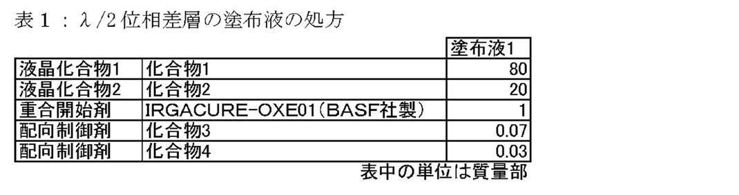

<反射層UV(短波長コレステリック液晶層)の作製>
λ/2位相差層上に、表2に示す塗布液UVを乾燥後の乾膜の厚みが3μmになるようにワイヤーバーを用いて室温にて塗布した。なお、表2に示す塗布液UV、塗布液B、塗布液G、塗布液R及び塗布液IRでは、溶媒は酢酸メチルとシクロヘキサノンとの8:2の混合液を用い、固形分濃度が25質量%になるように溶媒量を調整した。塗布層を室温にて30秒間乾燥させた後、85℃の雰囲気で2分間加熱し、その後60℃でフュージョン製Dバルブ(90mW/cmのランプ)にて出力60%で6~12秒間UV照射し、液晶層を作製し、PETベース付き反射層UVを得た。
λ/2位相差層上に、表2に示す塗布液UVを乾燥後の乾膜の厚みが3μmになるようにワイヤーバーを用いて室温にて塗布した。なお、表2に示す塗布液UV、塗布液B、塗布液G、塗布液R及び塗布液IRでは、溶媒は酢酸メチルとシクロヘキサノンとの8:2の混合液を用い、固形分濃度が25質量%になるように溶媒量を調整した。塗布層を室温にて30秒間乾燥させた後、85℃の雰囲気で2分間加熱し、その後60℃でフュージョン製Dバルブ(90mW/cmのランプ)にて出力60%で6~12秒間UV照射し、液晶層を作製し、PETベース付き反射層UVを得た。
<反射層B、反射層G、反射層R、IR層の作製>
塗布液UVの代わりに表2に示す塗布液B、塗布液G、塗布液R、塗布液IRをそれぞれ用い、東洋紡株式会社製コスモシャインA-4100(PET、厚み75μm)上に乾燥後の層の厚みが表3に示した厚みになるようにワイヤーバーを用いて室温にて塗布した以外は、反射層UVの作製と同様の手順で、反射層B、反射層G、反射層R、IR層をそれぞれ作製した。
塗布液UVの代わりに表2に示す塗布液B、塗布液G、塗布液R、塗布液IRをそれぞれ用い、東洋紡株式会社製コスモシャインA-4100(PET、厚み75μm)上に乾燥後の層の厚みが表3に示した厚みになるようにワイヤーバーを用いて室温にて塗布した以外は、反射層UVの作製と同様の手順で、反射層B、反射層G、反射層R、IR層をそれぞれ作製した。
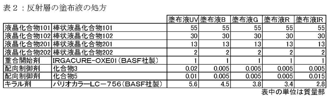

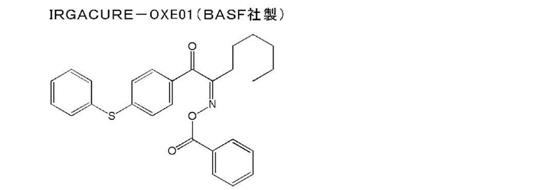
得られた積層体の反射層面に対して法線方向からの入射光(垂直入射)および法線方向から60度傾斜した入射光に対しての選択反射中心波長、ならびに反射光の円偏光のセンスを確認した。中心波長の測定は、JASCO社製の分光光度計V-670を用いて測定した。また、反射光の円偏光のセンスは、分光光度計の受光側に選択反射する円偏光のセンスが既知の円偏光板を設置して反射光強度を測定することで決定した。
また、λ/2位相差層の波長550nmの光に対しての位相差を以下の手順で測定した。アクリル板(厚み0.2mm、40mm角)にOCAテープ(日栄化工株式会社製 MHM-UVC15)を貼合した。OCAテープの離型フィルムを剥がし、OCAテープ上にPETベースつきλ/2位相差層をλ/2位相差層側の面で貼合した。PETを剥がして、アクリル板付きλ/2位相差層を作製した。アクリル板付きλ/2位相差層の位相差をAxometrics社製のAxoScanを用いて測定し、λ/2位相差層の位相差とした。
結果を表3に示す。
また、λ/2位相差層の波長550nmの光に対しての位相差を以下の手順で測定した。アクリル板(厚み0.2mm、40mm角)にOCAテープ(日栄化工株式会社製 MHM-UVC15)を貼合した。OCAテープの離型フィルムを剥がし、OCAテープ上にPETベースつきλ/2位相差層をλ/2位相差層側の面で貼合した。PETを剥がして、アクリル板付きλ/2位相差層を作製した。アクリル板付きλ/2位相差層の位相差をAxometrics社製のAxoScanを用いて測定し、λ/2位相差層の位相差とした。
結果を表3に示す。

<ハーフミラーフィルムHM-1~HM-3の作製>
上記と同様に作製したPETベース付きλ/2位相差層のλ/2位相差層側の面に反射層UV、反射層B、反射層G、反射層R、IR層を表4に示す組み合わせと積層順番になるように形成し、ハーフミラーフィルムHM-1~HM-3を作製した。各層の形成は、λ/2位相差層または反射層の上に、各層形成用の塗布液を乾燥後の層の厚みが表3に示した厚みになるように上記と同様に塗布し、その後、上記と同様に乾燥、UV照射することにより行った。
上記と同様に作製したPETベース付きλ/2位相差層のλ/2位相差層側の面に反射層UV、反射層B、反射層G、反射層R、IR層を表4に示す組み合わせと積層順番になるように形成し、ハーフミラーフィルムHM-1~HM-3を作製した。各層の形成は、λ/2位相差層または反射層の上に、各層形成用の塗布液を乾燥後の層の厚みが表3に示した厚みになるように上記と同様に塗布し、その後、上記と同様に乾燥、UV照射することにより行った。
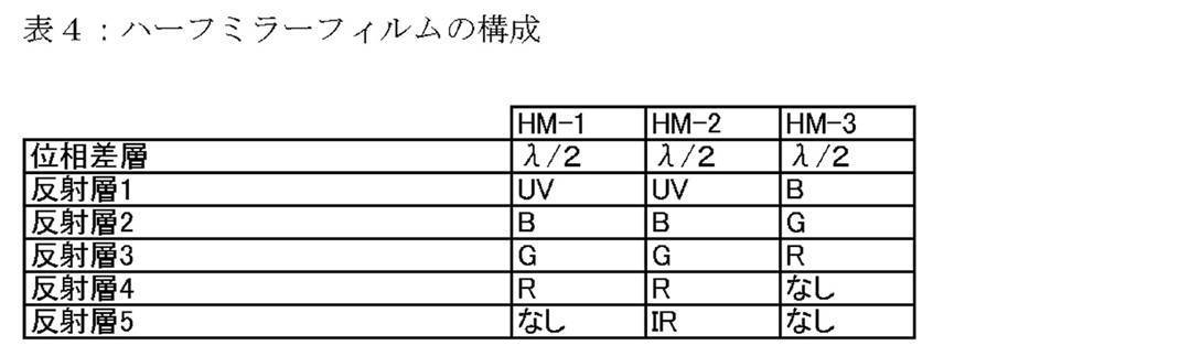
<実施例1~2、比較例1~2>
実施例1のウインドシールドガラスの作製
縦40cm横25cm厚み2mmのガラス板に接着層(OCAテープ:日栄化工株式会社製 MHM-UVC15)を接着し、次にOCAテープ上に上記で作製したハーフミラーフィルムHM-1を、ローラを用いて反射層がガラス面側になるように接着した。位相差層のベースとなっていたPETを剥離して、同じ形状にカッティングした積水化学社製の厚み0.38mmPVB(ポリビニルブチラール)を設置し、その上に縦40cm横25cm厚み3mmのガラス板を設置した。この際、ハーフミラーフィルムHM-1の位相差層の遅相軸方向が、厚み2mmのガラス側から見て、ガラスの短辺方向を基準に時計回り方向に60°の方向になるように配置した。この積層体を90℃、0.1気圧下で一時間保持した後に、115℃、13気圧で20分間加熱して気泡を除去し、実施例1のウインドシールドガラスを得た。
実施例2、比較例1~2のウインドシールドガラスの作製
ハーフミラーフィルムHM-1を表5に示すようにHM-2~HM-3のいずれかに変えるか、またはハーフミラーフィルムを用いなかった以外は実施例1のウインドシールドガラスと同様にして実施例2、比較例1、2のウインドシールドガラスの作製を行った。
ハーフミラーフィルムHM-1を表5に示すようにHM-2~HM-3のいずれかに変えるか、またはハーフミラーフィルムを用いなかった以外は実施例1のウインドシールドガラスと同様にして実施例2、比較例1、2のウインドシールドガラスの作製を行った。
<反射像の光学性能の評価>
光学評価は、図1に示す配置で行った。作製したウインドシールドガラスを、長辺を横に短辺を縦に厚み2mmのガラス側が下方になるように傾斜させて、このガラス側に画像を投映した。厚み2mmのガラス側から画像を投映し、その画像を観察した。画像は白輝度が200cdm-2で、色度がx=0.32、y=0.32のLG電子社製の液晶パネル23EA53VAを用いた。ウインドシールドガラスと液晶パネルとの距離は200mmとした。評価は表5に示した投映光の偏光方向について行った。表5のp偏光は図1でその電気ベクトル振動面が紙面に平行でs偏光は紙面に垂直である直線偏光である。
光学評価は、図1に示す配置で行った。作製したウインドシールドガラスを、長辺を横に短辺を縦に厚み2mmのガラス側が下方になるように傾斜させて、このガラス側に画像を投映した。厚み2mmのガラス側から画像を投映し、その画像を観察した。画像は白輝度が200cdm-2で、色度がx=0.32、y=0.32のLG電子社製の液晶パネル23EA53VAを用いた。ウインドシールドガラスと液晶パネルとの距離は200mmとした。評価は表5に示した投映光の偏光方向について行った。表5のp偏光は図1でその電気ベクトル振動面が紙面に平行でs偏光は紙面に垂直である直線偏光である。
輝度および色度は液晶パネル2に白ベタ画像を表示させてトプコン社製の輝度計BM-5Aを用いて測定した。
二重像の評価は、黒地に白色文字を液晶パネルに表示させて、文字の見え方を目視で評価した。評価の基準は以下のようにした。
A:文字は室内照明下および室内暗状態で可読
B:文字は室内照明下で可読。室内暗状態で難読(非許容レベル)
C:文字は室内照明下でも室内暗状態でも難読
二重像の評価は、黒地に白色文字を液晶パネルに表示させて、文字の見え方を目視で評価した。評価の基準は以下のようにした。
A:文字は室内照明下および室内暗状態で可読
B:文字は室内照明下で可読。室内暗状態で難読(非許容レベル)
C:文字は室内照明下でも室内暗状態でも難読
偏光サングラス着用での画像の視認性は、黒地に白色文字を液晶パネル2に表示させて、文字の見え方を、偏光サングラスを着用して目視で評価した。評価の基準は以下のようにした。
A:文字は室内照明下および室内暗状態で可読
B:文字は室内照明下で可読。室内暗状態で難読(許容レベル)
C:文字は室内照明下でも室内暗状態でも難読
A:文字は室内照明下および室内暗状態で可読
B:文字は室内照明下で可読。室内暗状態で難読(許容レベル)
C:文字は室内照明下でも室内暗状態でも難読
<外観の色味の評価>
ウインドシールドを外から見た時の色味の評価は、昼間の太陽光下において図1のガラスの外(11番の位置)から垂直方向から目視で色味を確認した。また、輝度計を用いて色度を測定した。
ウインドシールドを外から見た時の色味の評価は、昼間の太陽光下において図1のガラスの外(11番の位置)から垂直方向から目視で色味を確認した。また、輝度計を用いて色度を測定した。
<偏光サングラス着用時の外光評価>
偏光サングラス着用時に外光が透過した際の視認性評価は、昼間の太陽光下において図1のガラスの内(3番の位置)から偏光サングラスを着用してガラス外の水面での太陽の反射光の見え方を目視で評価した。評価の基準は以下のようにした。
A:水面の反射光はほとんど見えない。
A’:水面の反射光はわずかに見える。眩しくは見えない。(許容レベル)
B:水面の反射光は見える。眩しい。(非許容レベル)
偏光サングラス着用時に外光が透過した際の視認性評価は、昼間の太陽光下において図1のガラスの内(3番の位置)から偏光サングラスを着用してガラス外の水面での太陽の反射光の見え方を目視で評価した。評価の基準は以下のようにした。
A:水面の反射光はほとんど見えない。
A’:水面の反射光はわずかに見える。眩しくは見えない。(許容レベル)
B:水面の反射光は見える。眩しい。(非許容レベル)
(実施例3)
実施例2のウインドシールドガラスを用い、ウインドシールドガラスと液晶パネルとの距離を1500mmとして、上記と同じ評価を行なった。実施例2と比較してウインドシールドガラスと液晶パネルとの距離を大きくしているため、虚像結像位置が運転者(図1の符号3)からより遠くなる構成である。
評価結果を表5に示す。
実施例2のウインドシールドガラスを用い、ウインドシールドガラスと液晶パネルとの距離を1500mmとして、上記と同じ評価を行なった。実施例2と比較してウインドシールドガラスと液晶パネルとの距離を大きくしているため、虚像結像位置が運転者(図1の符号3)からより遠くなる構成である。
評価結果を表5に示す。

1 ウインドシールドガラス
2 液晶パネル
3 輝度計
11 観察位置
2 液晶パネル
3 輝度計
11 観察位置
Claims (18)
- 投映像表示部位を含むウインドシールドガラスであって、
前記投映像表示部位に円偏光反射層およびλ/2位相差層を含み、
前記円偏光反射層がコレステリック液晶層を4層以上含み、
前記4層以上のコレステリック液晶層のうちの一層が350nm以上490nm未満に選択反射の中心波長を有するコレステリック液晶層であり、
前記4層以上のコレステリック液晶層の選択反射の中心波長は互いに異なっているウインドシールドガラス。 - 前記4層以上のコレステリック液晶層のうち、前記λ/2位相差層に最も近いコレステリック液晶層が、350nm以上490nm未満に選択反射の中心波長を有する前記コレステリック液晶層である請求項1に記載のウインドシールドガラス。
- 前記円偏光反射層が、
490nm以上600nm未満に選択反射の中心波長を有するコレステリック液晶層、
600nm以上680nm未満に選択反射の中心波長を有するコレステリック液晶層、
および680nm以上850nm未満に選択反射の中心波長を有するコレステリック液晶層を含む請求項1または2に記載のウインドシールドガラス。 - 前記λ/2位相差層、
350nm以上490nm未満に選択反射の中心波長を有する前記コレステリック液晶層、
490nm以上600nm未満に選択反射の中心波長を有する前記コレステリック液晶層、
600nm以上680nm未満に選択反射の中心波長を有する前記コレステリック液晶層、
および680nm以上850nm未満に選択反射の中心波長を有する前記コレステリック液晶層がこの順に配置されている請求項3に記載のウインドシールドガラス。 - 前記λ/2位相差層の正面位相差が190nm~390nmの範囲である請求項1~4のいずれか一項に記載のウインドシールドガラス。
- 前記円偏光反射層に含まれる全てのコレステリック液晶層の螺旋のセンスが同一である請求項1~5のいずれか一項に記載のウインドシールドガラス。
- 前記円偏光反射層に対して前記λ/2位相差層側にある層の厚みの総計が0.5mm以上である請求項1~6のいずれか一項に記載のウインドシールドガラス。
- 第一のガラス板、第二のガラス板、および第一のガラス板と第二のガラス板との間の中間層を含み、前記中間層の少なくとも一部に前記円偏光反射層および前記λ/2位相差層を含み、前記第一のガラス板、前記円偏光反射層、前記λ/2位相差層、および前記第二のガラス板がこの順で積層されている請求項1~7のいずれか一項に記載のウインドシールドガラス。
- 前記中間層が樹脂膜である請求項8に記載のウインドシールドガラス。
- 前記樹脂膜がポリビニルブチラールを含む請求項9に記載のウインドシールドガラス。
- 前記投映像表示部位の鉛直上方向に対し、前記λ/2位相差層の遅相軸が+40°~+65°、または-40°~-65°の範囲にある請求項1~10のいずれか一項に記載のウインドシールドガラス。
- 前記円偏光反射層に含まれる全てのコレステリック液晶層の螺旋のセンスが右であり、前記投映像表示部位の鉛直上方向に対し、前記λ/2位相差層の遅相軸が、前記円偏光反射層に対して前記λ/2位相差層側から見て時計回りに40°~65°の範囲にある請求項1~10のいずれか一項に記載のウインドシールドガラス。
- 前記円偏光反射層に含まれる全てのコレステリック液晶層の螺旋のセンスが左であり、前記投映像表示部位の鉛直上方向に対し、前記λ/2位相差層の遅相軸が前記円偏光反射層に対して前記λ/2位相差層側から見て反時計回りに40°~65°の範囲にある請求項1~10のいずれか一項に記載のウインドシールドガラス。
- 前記コレステリック液晶層のいずれか1つ以上の選択反射の半値幅Δλが50nm以下である請求項1~13のいずれか一項に記載のウインドシールドガラス。
- 請求項1~14のいずれか一項に記載のウインドシールドガラスおよびプロジェクターを含むヘッドアップディスプレイシステムであって、
前記円偏光反射層に対して前記λ/2位相差層がプロジェクター側に配置されており、
前記プロジェクターからの入射光が投映像表示部位の法線に対し45°~70°の角度で入射する、
ヘッドアップディスプレイシステム。 - 前記入射光が入射面に平行な方向に振動するp偏光である請求項15に記載のヘッドアップディスプレイシステム。
- 前記入射光が、前記投映像表示部位の下方向から入射する請求項15または16に記載のヘッドアップディスプレイシステム。
- 円偏光反射層およびλ/2位相差層を含むハーフミラーフィルムであって、
前記円偏光反射層が、前記λ/2位相差層側から、350nm以上490nm未満に選択反射の中心波長を有するコレステリック液晶層、490nm以上600nm未満に選択反射の中心波長を有するコレステリック液晶層、600nm以上680nm未満に選択反射の中心波長を有するコレステリック液晶層、および680nm以上850nm未満に選択反射の中心波長を有するコレステリック液晶層をこの順で含むハーフミラーフィルム。
Priority Applications (3)
| Application Number | Priority Date | Filing Date | Title |
|---|---|---|---|
| CN201780065806.0A CN109863430A (zh) | 2016-11-04 | 2017-10-27 | 挡风玻璃、平视显示器系统及半反射镜膜 |
| EP17867431.3A EP3537190A4 (en) | 2016-11-04 | 2017-10-27 | WINDSHIELD GLASS, HEAD-UP DISPLAY SYSTEM AND HALF-MIRROR FOIL |
| US16/383,207 US20190235243A1 (en) | 2016-11-04 | 2019-04-12 | Windshield glass, head-up display system, and half-mirror film |
Applications Claiming Priority (4)
| Application Number | Priority Date | Filing Date | Title |
|---|---|---|---|
| JP2016215911 | 2016-11-04 | ||
| JP2016-215911 | 2016-11-04 | ||
| JP2017049013A JP6768567B2 (ja) | 2016-11-04 | 2017-03-14 | ウインドシールドガラス、ヘッドアップディスプレイシステム、およびハーフミラーフィルム |
| JP2017-049013 | 2017-03-14 |
Related Child Applications (1)
| Application Number | Title | Priority Date | Filing Date |
|---|---|---|---|
| US16/383,207 Continuation US20190235243A1 (en) | 2016-11-04 | 2019-04-12 | Windshield glass, head-up display system, and half-mirror film |
Publications (1)
| Publication Number | Publication Date |
|---|---|
| WO2018084076A1 true WO2018084076A1 (ja) | 2018-05-11 |
Family
ID=62076509
Family Applications (1)
| Application Number | Title | Priority Date | Filing Date |
|---|---|---|---|
| PCT/JP2017/038852 WO2018084076A1 (ja) | 2016-11-04 | 2017-10-27 | ウインドシールドガラス、ヘッドアップディスプレイシステム、およびハーフミラーフィルム |
Country Status (1)
| Country | Link |
|---|---|
| WO (1) | WO2018084076A1 (ja) |
Cited By (9)
| Publication number | Priority date | Publication date | Assignee | Title |
|---|---|---|---|---|
| CN109648941A (zh) * | 2018-12-12 | 2019-04-19 | 杭州炽云科技有限公司 | 一种汽车挡风玻璃及其制作方法 |
| WO2020166691A1 (ja) * | 2019-02-14 | 2020-08-20 | 富士フイルム株式会社 | 光学素子、導光素子および画像表示素子 |
| JPWO2020184714A1 (ja) * | 2019-03-13 | 2020-09-17 | ||
| CN113238378A (zh) * | 2021-04-14 | 2021-08-10 | 福耀玻璃工业集团股份有限公司 | 一种抬头显示系统 |
| JPWO2020075740A1 (ja) * | 2018-10-12 | 2021-09-30 | 富士フイルム株式会社 | 光学積層体、導光素子およびar表示デバイス |
| JPWO2020075738A1 (ja) * | 2018-10-12 | 2021-10-07 | 富士フイルム株式会社 | 光学積層体、導光素子および画像表示装置 |
| JPWO2022054902A1 (ja) * | 2020-09-14 | 2022-03-17 | ||
| WO2022196732A1 (ja) * | 2021-03-19 | 2022-09-22 | 日本化薬株式会社 | ヘッドアップディスプレイ用光学機能フィルム、光学積層体、機能性ガラス、およびヘッドアップディスプレイシステム |
| WO2023080116A1 (ja) * | 2021-11-05 | 2023-05-11 | 富士フイルム株式会社 | 反射フィルム、ウインドシールドガラス、ヘッドアップディスプレイシステム及びこのヘッドアップディスプレイシステムを有する輸送機 |
Citations (70)
| Publication number | Priority date | Publication date | Assignee | Title |
|---|---|---|---|---|
| US2367670A (en) | 1941-12-31 | 1945-01-23 | Du Pont | Cementing process |
| US2367661A (en) | 1941-12-31 | 1945-01-23 | Du Pont | Process of photopolymerization |
| US2448828A (en) | 1946-09-04 | 1948-09-07 | Du Pont | Photopolymerization |
| US2722512A (en) | 1952-10-23 | 1955-11-01 | Du Pont | Photopolymerization process |
| US2951758A (en) | 1957-05-17 | 1960-09-06 | Du Pont | Photopolymerizable compositions and elements |
| US3046127A (en) | 1957-10-07 | 1962-07-24 | Du Pont | Photopolymerizable compositions, elements and processes |
| US3549367A (en) | 1968-05-24 | 1970-12-22 | Du Pont | Photopolymerizable compositions containing triarylimidazolyl dimers and p-aminophenyl ketones |
| US4212970A (en) | 1977-11-28 | 1980-07-15 | Fuji Photo Film Co., Ltd. | 2-Halomethyl-5-vinyl-1,3,4-oxadiazole compounds |
| US4239850A (en) | 1977-11-29 | 1980-12-16 | Fuji Photo Film Co., Ltd. | Photopolymerizable composition |
| JPS60105667A (ja) | 1983-10-12 | 1985-06-11 | ヘキスト・アクチエンゲゼルシヤフト | トリクロルメチル基を有する感光性化合物及びその製法 |
| US4683327A (en) | 1985-06-24 | 1987-07-28 | Celanese Corporation | Anisotropic heat-curable acrylic terminated monomers |
| JPS6340799B2 (ja) | 1978-07-14 | 1988-08-12 | Basf Ag | |
| JPH01272551A (ja) | 1988-04-22 | 1989-10-31 | Dainippon Printing Co Ltd | 重合性2官能アクリレートモノマー |
| JPH02141720A (ja) | 1988-11-23 | 1990-05-31 | Nippon Denso Co Ltd | ヘッドアップディスプレイ装置 |
| US5013134A (en) | 1989-09-28 | 1991-05-07 | Hughes Aircraft Company | Ghost-free automotive head-up display employing a wedged windshield |
| JPH0616616A (ja) | 1992-07-03 | 1994-01-25 | Canon Inc | 反応性液晶性化合物、高分子液晶化合物、液晶組成物および液晶素子 |
| JPH07110469A (ja) | 1993-08-16 | 1995-04-25 | Dainippon Ink & Chem Inc | 液晶表示素子及びその製造方法 |
| WO1995022586A1 (de) | 1994-02-19 | 1995-08-24 | Basf Aktiengesellschaft | Neue polymerisierbare flüssigkristalline verbindungen |
| WO1995024455A1 (de) | 1994-03-11 | 1995-09-14 | Basf Aktiengesellschaft | Neue polymerisierbare flüssigkristalline verbindungen |
| JPH07270711A (ja) | 1994-03-30 | 1995-10-20 | Canon Inc | 情報表示装置 |
| WO1997000600A2 (de) | 1995-09-01 | 1997-01-09 | Basf Aktiengesellschaft | Polymerisierbare flüssigkristalline verbindungen |
| US5622648A (en) | 1993-10-15 | 1997-04-22 | Merck Patent Gesellschaft Mit Beschrankter Haftung | Reactive liquid crystal compounds |
| JPH1029997A (ja) | 1996-03-04 | 1998-02-03 | Ciba Specialty Chem Holding Inc | アルキルフェニルビスアシルホスフィンオキサイドおよび光開始剤混合物 |
| JPH1096874A (ja) | 1996-05-24 | 1998-04-14 | Asahi Glass Co Ltd | 車両用ウインドシールドガラスおよびヘッドアップディスプレイ装置 |
| JPH1095788A (ja) | 1996-08-28 | 1998-04-14 | Ciba Specialty Chem Holding Inc | 光開始剤としての分子錯化合物 |
| WO1998023580A1 (de) | 1996-11-27 | 1998-06-04 | Basf Aktiengesellschaft | Polymerisierbare oligomesogene |
| US5770107A (en) | 1995-10-05 | 1998-06-23 | Merck Patent Gesellschaft Mit Beschrankter Haftung | Reactive liquid crystalline compound |
| WO1998052905A1 (en) | 1997-05-22 | 1998-11-26 | Rolic Ag | New polymerisable liquid crystalline compounds |
| JPH1180081A (ja) | 1997-09-05 | 1999-03-23 | Dainippon Ink & Chem Inc | 液晶性(メタ)アクリレート化合物と組成物及びこれを用いた光学異方体 |
| JP2000066385A (ja) | 1998-08-18 | 2000-03-03 | Ciba Specialty Chem Holding Inc | 高感度で高レジスト厚さのi線ホトレジスト用スルホニルオキシム類 |
| JP2000080068A (ja) | 1998-06-26 | 2000-03-21 | Ciba Specialty Chem Holding Inc | 新規o―アシルオキシム光開始剤 |
| JP2000221449A (ja) | 1999-01-29 | 2000-08-11 | Arisawa Mfg Co Ltd | 映像装置 |
| JP2001233842A (ja) | 1999-12-15 | 2001-08-28 | Ciba Specialty Chem Holding Inc | オキシムエステルの光開始剤 |
| JP2001328973A (ja) | 2000-03-13 | 2001-11-27 | Fuji Photo Film Co Ltd | 重合性液晶化合物および光学異方性素子 |
| JP2002080478A (ja) | 2000-06-27 | 2002-03-19 | Fuji Photo Film Co Ltd | 光反応型光学活性化合物、光反応型カイラル剤、液晶組成物、液晶カラーフィルタ、光学フィルム、記録媒体、及び液晶の捻れ構造を変化させる方法 |
| JP2002080851A (ja) | 2000-06-27 | 2002-03-22 | Fuji Photo Film Co Ltd | 光反応型カイラル剤、液晶組成物、液晶カラーフィルタ、光学フィルム、記録媒体、及び液晶の捻れ構造を変化させる方法 |
| JP2002302487A (ja) | 2000-12-14 | 2002-10-18 | Fuji Photo Film Co Ltd | 光学活性化合物、光反応型キラル剤、液晶組成物、液晶の螺旋構造を変化させる方法、液晶の螺旋構造を固定化する方法、液晶カラーフィルター、光学フィルムおよび記録媒体 |
| JP2003098470A (ja) | 2001-09-21 | 2003-04-03 | Asahi Glass Co Ltd | ヘッドアップディスプレイ装置 |
| JP2003287623A (ja) | 2002-01-23 | 2003-10-10 | Nitto Denko Corp | 光学フィルム、その製造方法、およびこれを用いた位相差フィルムならびに偏光板 |
| JP2006512622A (ja) | 2002-12-31 | 2006-04-13 | スリーエム イノベイティブ プロパティズ カンパニー | 偏光光源および広角p偏光反射偏光子を備えたヘッドアップディスプレイ |
| JP2006342166A (ja) | 2001-06-11 | 2006-12-21 | Ciba Specialty Chem Holding Inc | 組み合わされた構造を有するオキシムエステルの光開始剤 |
| JP2007523369A (ja) | 2004-02-04 | 2007-08-16 | マイクロビジョン,インク. | 走査ビームヘッドアップ表示装置および関連システム、および方法 |
| JP2007272185A (ja) | 2006-03-10 | 2007-10-18 | Fujifilm Corp | 組成物、位相差板、液晶表示装置、平均チルト角調整剤、平均チルト角の調整方法 |
| JP4223071B2 (ja) | 2006-12-27 | 2009-02-12 | 株式会社Adeka | オキシムエステル化合物及び該化合物を含有する光重合開始剤 |
| JP2009150947A (ja) | 2007-12-19 | 2009-07-09 | Hitachi Ltd | 車両用ヘッドアップディスプレイ装置 |
| JP2010070543A (ja) | 2008-08-18 | 2010-04-02 | Asahi Glass Co Ltd | 二官能重合性化合物、液晶組成物、光学異方性材料および光学素子 |
| JP2010145745A (ja) | 2008-12-18 | 2010-07-01 | Equos Research Co Ltd | 画像形成装置、及び、ヘッドアップディスプレイ装置 |
| JP2010181852A (ja) | 2008-07-14 | 2010-08-19 | Fujifilm Corp | 光学異方性膜、光学異方性膜の製造方法、液晶セル用基板、及び液晶表示装置 |
| JP2010262028A (ja) | 2009-04-30 | 2010-11-18 | Nippon Steel Chem Co Ltd | ブラックマトリックス用感光性樹脂組成物 |
| JP2011505330A (ja) | 2007-12-07 | 2011-02-24 | サン−ゴバン グラス フランス | 合わせガラスからなる曲面の車両用フロントガラス |
| JP4725516B2 (ja) | 2004-06-25 | 2011-07-13 | 旭硝子株式会社 | 重合性液晶化合物、液晶組成物、および光学異方性材料 |
| JP2012203237A (ja) | 2011-03-25 | 2012-10-22 | Fujifilm Corp | 光反射性フィルムの製造方法 |
| JP2012208494A (ja) | 2011-03-17 | 2012-10-25 | Fujifilm Corp | 着色感放射線性組成物、着色硬化膜、カラーフィルタ及びカラーフィルタの製造方法、固体撮像素子、液晶表示装置、並びに、染料の製造方法 |
| JP2012226303A (ja) | 2011-12-21 | 2012-11-15 | Pioneer Electronic Corp | 光源ユニット及びヘッドアップディスプレイ |
| JP2013114249A (ja) | 2011-12-01 | 2013-06-10 | Toppan Printing Co Ltd | 黒色感光性樹脂組成物およびカラーフィルタ |
| JP2013112631A (ja) | 2011-11-28 | 2013-06-10 | Dic Corp | 重合性液晶化合物 |
| JP2013228674A (ja) | 2012-03-28 | 2013-11-07 | Nippon Seiki Co Ltd | 車両用表示装置 |
| JP2014500852A (ja) | 2010-10-05 | 2014-01-16 | ビーエーエスエフ ソシエタス・ヨーロピア | ベンゾカルバゾール化合物のオキシムエステル誘導体ならびに前記誘導体の光重合性の組成物における光開始剤としての使用 |
| JP2014034581A (ja) | 2012-08-07 | 2014-02-24 | Fujifilm Corp | 液晶組成物、高分子、フィルムおよびコレステリック液晶 |
| JP2014137466A (ja) | 2013-01-16 | 2014-07-28 | Jsr Corp | 感放射線性着色組成物、着色硬化膜及び表示素子 |
| WO2015115390A1 (ja) | 2014-01-28 | 2015-08-06 | 富士フイルム株式会社 | 重合性化合物、重合性組成物、フィルム、および投映像表示用ハーフミラー |
| WO2015141759A1 (ja) * | 2014-03-20 | 2015-09-24 | 富士フイルム株式会社 | 反射部材、投映スクリーン、コンバイナ、および、遮熱部材 |
| WO2015147243A1 (ja) | 2014-03-28 | 2015-10-01 | 富士フイルム株式会社 | 重合性化合物、ポリマー、重合性組成物、フィルム、および投映像表示用ハーフミラー |
| WO2016035873A1 (ja) | 2014-09-05 | 2016-03-10 | 富士フイルム株式会社 | 重合性化合物、ポリマー、重合性組成物、およびフィルム |
| WO2016047648A1 (ja) | 2014-09-25 | 2016-03-31 | 富士フイルム株式会社 | 重合性化合物を含む重合性組成物、フィルム、および投映像表示用ハーフミラー |
| WO2016052367A1 (ja) | 2014-09-29 | 2016-04-07 | 富士フイルム株式会社 | 投映像表示用部材および投映像表示システム |
| JP2016053149A (ja) | 2014-03-28 | 2016-04-14 | 富士フイルム株式会社 | 重合性化合物、ポリマー、重合性組成物、フィルム、および投映像表示用ハーフミラー |
| WO2016056617A1 (ja) * | 2014-10-10 | 2016-04-14 | 日本化薬株式会社 | 光反射フィルム、ならびにこれを用いた光制御フィルム、光学フィルム、機能性ガラスおよびヘッドアップディスプレイ |
| JP2016153281A (ja) * | 2015-02-20 | 2016-08-25 | 富士フイルム株式会社 | ウインドシールドガラスおよびヘッドアップディスプレイシステム |
| JP2017015902A (ja) | 2015-06-30 | 2017-01-19 | パナソニックIpマネジメント株式会社 | 表示装置、表示方法および表示媒体 |
-
2017
- 2017-10-27 WO PCT/JP2017/038852 patent/WO2018084076A1/ja unknown
Patent Citations (72)
| Publication number | Priority date | Publication date | Assignee | Title |
|---|---|---|---|---|
| US2367670A (en) | 1941-12-31 | 1945-01-23 | Du Pont | Cementing process |
| US2367661A (en) | 1941-12-31 | 1945-01-23 | Du Pont | Process of photopolymerization |
| US2448828A (en) | 1946-09-04 | 1948-09-07 | Du Pont | Photopolymerization |
| US2722512A (en) | 1952-10-23 | 1955-11-01 | Du Pont | Photopolymerization process |
| US2951758A (en) | 1957-05-17 | 1960-09-06 | Du Pont | Photopolymerizable compositions and elements |
| US3046127A (en) | 1957-10-07 | 1962-07-24 | Du Pont | Photopolymerizable compositions, elements and processes |
| US3549367A (en) | 1968-05-24 | 1970-12-22 | Du Pont | Photopolymerizable compositions containing triarylimidazolyl dimers and p-aminophenyl ketones |
| US4212970A (en) | 1977-11-28 | 1980-07-15 | Fuji Photo Film Co., Ltd. | 2-Halomethyl-5-vinyl-1,3,4-oxadiazole compounds |
| US4239850A (en) | 1977-11-29 | 1980-12-16 | Fuji Photo Film Co., Ltd. | Photopolymerizable composition |
| JPS6340799B2 (ja) | 1978-07-14 | 1988-08-12 | Basf Ag | |
| JPS60105667A (ja) | 1983-10-12 | 1985-06-11 | ヘキスト・アクチエンゲゼルシヤフト | トリクロルメチル基を有する感光性化合物及びその製法 |
| US4683327A (en) | 1985-06-24 | 1987-07-28 | Celanese Corporation | Anisotropic heat-curable acrylic terminated monomers |
| JPH01272551A (ja) | 1988-04-22 | 1989-10-31 | Dainippon Printing Co Ltd | 重合性2官能アクリレートモノマー |
| JPH02141720A (ja) | 1988-11-23 | 1990-05-31 | Nippon Denso Co Ltd | ヘッドアップディスプレイ装置 |
| US5013134A (en) | 1989-09-28 | 1991-05-07 | Hughes Aircraft Company | Ghost-free automotive head-up display employing a wedged windshield |
| JPH0616616A (ja) | 1992-07-03 | 1994-01-25 | Canon Inc | 反応性液晶性化合物、高分子液晶化合物、液晶組成物および液晶素子 |
| JPH07110469A (ja) | 1993-08-16 | 1995-04-25 | Dainippon Ink & Chem Inc | 液晶表示素子及びその製造方法 |
| US5622648A (en) | 1993-10-15 | 1997-04-22 | Merck Patent Gesellschaft Mit Beschrankter Haftung | Reactive liquid crystal compounds |
| WO1995022586A1 (de) | 1994-02-19 | 1995-08-24 | Basf Aktiengesellschaft | Neue polymerisierbare flüssigkristalline verbindungen |
| WO1995024455A1 (de) | 1994-03-11 | 1995-09-14 | Basf Aktiengesellschaft | Neue polymerisierbare flüssigkristalline verbindungen |
| JPH07270711A (ja) | 1994-03-30 | 1995-10-20 | Canon Inc | 情報表示装置 |
| WO1997000600A2 (de) | 1995-09-01 | 1997-01-09 | Basf Aktiengesellschaft | Polymerisierbare flüssigkristalline verbindungen |
| US5770107A (en) | 1995-10-05 | 1998-06-23 | Merck Patent Gesellschaft Mit Beschrankter Haftung | Reactive liquid crystalline compound |
| JPH1029997A (ja) | 1996-03-04 | 1998-02-03 | Ciba Specialty Chem Holding Inc | アルキルフェニルビスアシルホスフィンオキサイドおよび光開始剤混合物 |
| JPH1096874A (ja) | 1996-05-24 | 1998-04-14 | Asahi Glass Co Ltd | 車両用ウインドシールドガラスおよびヘッドアップディスプレイ装置 |
| JPH1095788A (ja) | 1996-08-28 | 1998-04-14 | Ciba Specialty Chem Holding Inc | 光開始剤としての分子錯化合物 |
| WO1998023580A1 (de) | 1996-11-27 | 1998-06-04 | Basf Aktiengesellschaft | Polymerisierbare oligomesogene |
| WO1998052905A1 (en) | 1997-05-22 | 1998-11-26 | Rolic Ag | New polymerisable liquid crystalline compounds |
| JPH1180081A (ja) | 1997-09-05 | 1999-03-23 | Dainippon Ink & Chem Inc | 液晶性(メタ)アクリレート化合物と組成物及びこれを用いた光学異方体 |
| JP2000080068A (ja) | 1998-06-26 | 2000-03-21 | Ciba Specialty Chem Holding Inc | 新規o―アシルオキシム光開始剤 |
| JP4454067B2 (ja) | 1998-06-26 | 2010-04-21 | チバ ホールディング インコーポレーテッド | 新規o−アシルオキシム光開始剤 |
| JP2000066385A (ja) | 1998-08-18 | 2000-03-03 | Ciba Specialty Chem Holding Inc | 高感度で高レジスト厚さのi線ホトレジスト用スルホニルオキシム類 |
| JP2000221449A (ja) | 1999-01-29 | 2000-08-11 | Arisawa Mfg Co Ltd | 映像装置 |
| JP2001233842A (ja) | 1999-12-15 | 2001-08-28 | Ciba Specialty Chem Holding Inc | オキシムエステルの光開始剤 |
| JP2001328973A (ja) | 2000-03-13 | 2001-11-27 | Fuji Photo Film Co Ltd | 重合性液晶化合物および光学異方性素子 |
| JP2002080478A (ja) | 2000-06-27 | 2002-03-19 | Fuji Photo Film Co Ltd | 光反応型光学活性化合物、光反応型カイラル剤、液晶組成物、液晶カラーフィルタ、光学フィルム、記録媒体、及び液晶の捻れ構造を変化させる方法 |
| JP2002080851A (ja) | 2000-06-27 | 2002-03-22 | Fuji Photo Film Co Ltd | 光反応型カイラル剤、液晶組成物、液晶カラーフィルタ、光学フィルム、記録媒体、及び液晶の捻れ構造を変化させる方法 |
| JP2002302487A (ja) | 2000-12-14 | 2002-10-18 | Fuji Photo Film Co Ltd | 光学活性化合物、光反応型キラル剤、液晶組成物、液晶の螺旋構造を変化させる方法、液晶の螺旋構造を固定化する方法、液晶カラーフィルター、光学フィルムおよび記録媒体 |
| JP2006342166A (ja) | 2001-06-11 | 2006-12-21 | Ciba Specialty Chem Holding Inc | 組み合わされた構造を有するオキシムエステルの光開始剤 |
| JP2003098470A (ja) | 2001-09-21 | 2003-04-03 | Asahi Glass Co Ltd | ヘッドアップディスプレイ装置 |
| JP2003287623A (ja) | 2002-01-23 | 2003-10-10 | Nitto Denko Corp | 光学フィルム、その製造方法、およびこれを用いた位相差フィルムならびに偏光板 |
| JP2006512622A (ja) | 2002-12-31 | 2006-04-13 | スリーエム イノベイティブ プロパティズ カンパニー | 偏光光源および広角p偏光反射偏光子を備えたヘッドアップディスプレイ |
| JP2007523369A (ja) | 2004-02-04 | 2007-08-16 | マイクロビジョン,インク. | 走査ビームヘッドアップ表示装置および関連システム、および方法 |
| JP4725516B2 (ja) | 2004-06-25 | 2011-07-13 | 旭硝子株式会社 | 重合性液晶化合物、液晶組成物、および光学異方性材料 |
| JP2007272185A (ja) | 2006-03-10 | 2007-10-18 | Fujifilm Corp | 組成物、位相差板、液晶表示装置、平均チルト角調整剤、平均チルト角の調整方法 |
| JP4223071B2 (ja) | 2006-12-27 | 2009-02-12 | 株式会社Adeka | オキシムエステル化合物及び該化合物を含有する光重合開始剤 |
| JP2011505330A (ja) | 2007-12-07 | 2011-02-24 | サン−ゴバン グラス フランス | 合わせガラスからなる曲面の車両用フロントガラス |
| JP2009150947A (ja) | 2007-12-19 | 2009-07-09 | Hitachi Ltd | 車両用ヘッドアップディスプレイ装置 |
| JP2010181852A (ja) | 2008-07-14 | 2010-08-19 | Fujifilm Corp | 光学異方性膜、光学異方性膜の製造方法、液晶セル用基板、及び液晶表示装置 |
| JP2010070543A (ja) | 2008-08-18 | 2010-04-02 | Asahi Glass Co Ltd | 二官能重合性化合物、液晶組成物、光学異方性材料および光学素子 |
| JP2010145745A (ja) | 2008-12-18 | 2010-07-01 | Equos Research Co Ltd | 画像形成装置、及び、ヘッドアップディスプレイ装置 |
| JP2010262028A (ja) | 2009-04-30 | 2010-11-18 | Nippon Steel Chem Co Ltd | ブラックマトリックス用感光性樹脂組成物 |
| JP2014500852A (ja) | 2010-10-05 | 2014-01-16 | ビーエーエスエフ ソシエタス・ヨーロピア | ベンゾカルバゾール化合物のオキシムエステル誘導体ならびに前記誘導体の光重合性の組成物における光開始剤としての使用 |
| JP2012208494A (ja) | 2011-03-17 | 2012-10-25 | Fujifilm Corp | 着色感放射線性組成物、着色硬化膜、カラーフィルタ及びカラーフィルタの製造方法、固体撮像素子、液晶表示装置、並びに、染料の製造方法 |
| JP2012203237A (ja) | 2011-03-25 | 2012-10-22 | Fujifilm Corp | 光反射性フィルムの製造方法 |
| JP2013112631A (ja) | 2011-11-28 | 2013-06-10 | Dic Corp | 重合性液晶化合物 |
| JP2013114249A (ja) | 2011-12-01 | 2013-06-10 | Toppan Printing Co Ltd | 黒色感光性樹脂組成物およびカラーフィルタ |
| JP2012226303A (ja) | 2011-12-21 | 2012-11-15 | Pioneer Electronic Corp | 光源ユニット及びヘッドアップディスプレイ |
| JP2013228674A (ja) | 2012-03-28 | 2013-11-07 | Nippon Seiki Co Ltd | 車両用表示装置 |
| JP2014034581A (ja) | 2012-08-07 | 2014-02-24 | Fujifilm Corp | 液晶組成物、高分子、フィルムおよびコレステリック液晶 |
| JP2014137466A (ja) | 2013-01-16 | 2014-07-28 | Jsr Corp | 感放射線性着色組成物、着色硬化膜及び表示素子 |
| WO2015115390A1 (ja) | 2014-01-28 | 2015-08-06 | 富士フイルム株式会社 | 重合性化合物、重合性組成物、フィルム、および投映像表示用ハーフミラー |
| JP2015163596A (ja) | 2014-01-28 | 2015-09-10 | 富士フイルム株式会社 | 重合性化合物、ポリマー、重合性組成物、フィルム、および投映像表示用ハーフミラー |
| WO2015141759A1 (ja) * | 2014-03-20 | 2015-09-24 | 富士フイルム株式会社 | 反射部材、投映スクリーン、コンバイナ、および、遮熱部材 |
| WO2015147243A1 (ja) | 2014-03-28 | 2015-10-01 | 富士フイルム株式会社 | 重合性化合物、ポリマー、重合性組成物、フィルム、および投映像表示用ハーフミラー |
| JP2016053149A (ja) | 2014-03-28 | 2016-04-14 | 富士フイルム株式会社 | 重合性化合物、ポリマー、重合性組成物、フィルム、および投映像表示用ハーフミラー |
| WO2016035873A1 (ja) | 2014-09-05 | 2016-03-10 | 富士フイルム株式会社 | 重合性化合物、ポリマー、重合性組成物、およびフィルム |
| WO2016047648A1 (ja) | 2014-09-25 | 2016-03-31 | 富士フイルム株式会社 | 重合性化合物を含む重合性組成物、フィルム、および投映像表示用ハーフミラー |
| WO2016052367A1 (ja) | 2014-09-29 | 2016-04-07 | 富士フイルム株式会社 | 投映像表示用部材および投映像表示システム |
| WO2016056617A1 (ja) * | 2014-10-10 | 2016-04-14 | 日本化薬株式会社 | 光反射フィルム、ならびにこれを用いた光制御フィルム、光学フィルム、機能性ガラスおよびヘッドアップディスプレイ |
| JP2016153281A (ja) * | 2015-02-20 | 2016-08-25 | 富士フイルム株式会社 | ウインドシールドガラスおよびヘッドアップディスプレイシステム |
| JP2017015902A (ja) | 2015-06-30 | 2017-01-19 | パナソニックIpマネジメント株式会社 | 表示装置、表示方法および表示媒体 |
Non-Patent Citations (5)
| Title |
|---|
| "Handbook of liquid crystals Editorial Committee of Handbook of liquid crystals", MARUZEN, pages: 196 |
| "Liquid Crystal Chemistry Experiment Introduction", 2007, SIGMA PUBLICATION, pages: 46 |
| "Liquid Crystal Device Handbooks", vol. 4-3, 1989, article "Chiral Agents for TN and STN", pages: 199 |
| ADVANCED MATERIAL, vol. 5, 1993, pages 107 |
| MAKROMOL. CHEM., vol. 190, 1989, pages 2255 |
Cited By (16)
| Publication number | Priority date | Publication date | Assignee | Title |
|---|---|---|---|---|
| JP7166354B2 (ja) | 2018-10-12 | 2022-11-07 | 富士フイルム株式会社 | 光学積層体、導光素子およびar表示デバイス |
| JPWO2020075740A1 (ja) * | 2018-10-12 | 2021-09-30 | 富士フイルム株式会社 | 光学積層体、導光素子およびar表示デバイス |
| JPWO2020075738A1 (ja) * | 2018-10-12 | 2021-10-07 | 富士フイルム株式会社 | 光学積層体、導光素子および画像表示装置 |
| JP7175995B2 (ja) | 2018-10-12 | 2022-11-21 | 富士フイルム株式会社 | 光学積層体、導光素子および画像表示装置 |
| CN109648941A (zh) * | 2018-12-12 | 2019-04-19 | 杭州炽云科技有限公司 | 一种汽车挡风玻璃及其制作方法 |
| WO2020166691A1 (ja) * | 2019-02-14 | 2020-08-20 | 富士フイルム株式会社 | 光学素子、導光素子および画像表示素子 |
| JPWO2020184714A1 (ja) * | 2019-03-13 | 2020-09-17 | ||
| WO2020184714A1 (ja) * | 2019-03-13 | 2020-09-17 | 富士フイルム株式会社 | 投映像表示用部材、ウインドシールドガラスおよびヘッドアップディスプレイシステム |
| JP7382392B2 (ja) | 2019-03-13 | 2023-11-16 | 富士フイルム株式会社 | 投映像表示用部材、ウインドシールドガラスおよびヘッドアップディスプレイシステム |
| WO2022054902A1 (ja) * | 2020-09-14 | 2022-03-17 | 東レ株式会社 | ヘッドアップディスプレイシステム |
| JPWO2022054902A1 (ja) * | 2020-09-14 | 2022-03-17 | ||
| JP7279814B2 (ja) | 2020-09-14 | 2023-05-23 | 東レ株式会社 | ヘッドアップディスプレイシステム |
| WO2022196732A1 (ja) * | 2021-03-19 | 2022-09-22 | 日本化薬株式会社 | ヘッドアップディスプレイ用光学機能フィルム、光学積層体、機能性ガラス、およびヘッドアップディスプレイシステム |
| CN113238378B (zh) * | 2021-04-14 | 2022-07-19 | 福耀玻璃工业集团股份有限公司 | 一种抬头显示系统 |
| CN113238378A (zh) * | 2021-04-14 | 2021-08-10 | 福耀玻璃工业集团股份有限公司 | 一种抬头显示系统 |
| WO2023080116A1 (ja) * | 2021-11-05 | 2023-05-11 | 富士フイルム株式会社 | 反射フィルム、ウインドシールドガラス、ヘッドアップディスプレイシステム及びこのヘッドアップディスプレイシステムを有する輸送機 |
Similar Documents
| Publication | Publication Date | Title |
|---|---|---|
| JP6114728B2 (ja) | 投映像表示用部材および投映像表示システム | |
| WO2018084076A1 (ja) | ウインドシールドガラス、ヘッドアップディスプレイシステム、およびハーフミラーフィルム | |
| US10649325B2 (en) | Member for displaying projected image and projected image display system | |
| JP6768567B2 (ja) | ウインドシールドガラス、ヘッドアップディスプレイシステム、およびハーフミラーフィルム | |
| WO2016133187A1 (ja) | ウインドシールドガラスおよびヘッドアップディスプレイシステム | |
| JP6513784B2 (ja) | コンバイナおよびヘッドアップディスプレイシステム | |
| JP6602727B2 (ja) | ヘッドアップディスプレイシステム | |
| WO2017030176A1 (ja) | 投映システムおよび投映システムの中間像スクリーンの製造方法 | |
| US11947109B2 (en) | Projection image-displaying member, windshield glass, and head-up display system | |
| US11314087B2 (en) | Projection image-displaying member, windshield glass, and head-up display system | |
| JPWO2015141759A1 (ja) | 反射部材、投映スクリーン、コンバイナ、および、遮熱部材 | |
| WO2018110066A1 (ja) | ウインドシールドガラス、ヘッドアップディスプレイシステム、および積層フィルム | |
| US20200333598A1 (en) | Method for producing screen image-displaying laminated glass, screen image-displaying laminated glass, and image display system | |
| JP2018200459A (ja) | 実像表示用部材、および表示システム | |
| JP2019012211A (ja) | 投映像表示用ハーフミラー、ウインドシールドガラスおよびヘッドアップディスプレイシステム | |
| US20230314669A1 (en) | Reflection film, windshield glass, and head-up display system | |
| JP7260449B2 (ja) | 投映像表示用部材、ウインドシールドガラスおよびヘッドアップディスプレイシステム | |
| US11860361B2 (en) | Reflection film, windshield glass, and head-up display system | |
| JP6676015B2 (ja) | 合わせガラスの製造方法 | |
| JP2018199317A (ja) | 積層フィルム、合わせガラス中間膜シートの製造方法、および合わせガラスの製造方法 | |
| WO2021246402A1 (ja) | 反射フィルム、合わせガラスの製造方法、および、合わせガラス |
Legal Events
| Date | Code | Title | Description |
|---|---|---|---|
| 121 | Ep: the epo has been informed by wipo that ep was designated in this application |
Ref document number: 17867431 Country of ref document: EP Kind code of ref document: A1 |
|
| NENP | Non-entry into the national phase |
Ref country code: DE |
|
| ENP | Entry into the national phase |
Ref document number: 2017867431 Country of ref document: EP Effective date: 20190604 |