WO2019065254A1 - 正極活物質、及び、その製造方法、並びに、正極、及びリチウムイオン電池 - Google Patents
正極活物質、及び、その製造方法、並びに、正極、及びリチウムイオン電池 Download PDFInfo
- Publication number
- WO2019065254A1 WO2019065254A1 PCT/JP2018/033869 JP2018033869W WO2019065254A1 WO 2019065254 A1 WO2019065254 A1 WO 2019065254A1 JP 2018033869 W JP2018033869 W JP 2018033869W WO 2019065254 A1 WO2019065254 A1 WO 2019065254A1
- Authority
- WO
- WIPO (PCT)
- Prior art keywords
- positive electrode
- active material
- electrode active
- surface area
- particles
- Prior art date
Links
Classifications
-
- H—ELECTRICITY
- H01—ELECTRIC ELEMENTS
- H01M—PROCESSES OR MEANS, e.g. BATTERIES, FOR THE DIRECT CONVERSION OF CHEMICAL ENERGY INTO ELECTRICAL ENERGY
- H01M4/00—Electrodes
- H01M4/02—Electrodes composed of, or comprising, active material
- H01M4/36—Selection of substances as active materials, active masses, active liquids
- H01M4/362—Composites
- H01M4/366—Composites as layered products
-
- C—CHEMISTRY; METALLURGY
- C01—INORGANIC CHEMISTRY
- C01G—COMPOUNDS CONTAINING METALS NOT COVERED BY SUBCLASSES C01D OR C01F
- C01G33/00—Compounds of niobium
-
- C—CHEMISTRY; METALLURGY
- C01—INORGANIC CHEMISTRY
- C01G—COMPOUNDS CONTAINING METALS NOT COVERED BY SUBCLASSES C01D OR C01F
- C01G53/00—Compounds of nickel
- C01G53/40—Nickelates
- C01G53/42—Nickelates containing alkali metals, e.g. LiNiO2
- C01G53/44—Nickelates containing alkali metals, e.g. LiNiO2 containing manganese
- C01G53/50—Nickelates containing alkali metals, e.g. LiNiO2 containing manganese of the type [MnO2]n-, e.g. Li(NixMn1-x)O2, Li(MyNixMn1-x-y)O2
-
- H—ELECTRICITY
- H01—ELECTRIC ELEMENTS
- H01M—PROCESSES OR MEANS, e.g. BATTERIES, FOR THE DIRECT CONVERSION OF CHEMICAL ENERGY INTO ELECTRICAL ENERGY
- H01M4/00—Electrodes
- H01M4/02—Electrodes composed of, or comprising, active material
- H01M4/36—Selection of substances as active materials, active masses, active liquids
- H01M4/48—Selection of substances as active materials, active masses, active liquids of inorganic oxides or hydroxides
- H01M4/50—Selection of substances as active materials, active masses, active liquids of inorganic oxides or hydroxides of manganese
- H01M4/505—Selection of substances as active materials, active masses, active liquids of inorganic oxides or hydroxides of manganese of mixed oxides or hydroxides containing manganese for inserting or intercalating light metals, e.g. LiMn2O4 or LiMn2OxFy
-
- H—ELECTRICITY
- H01—ELECTRIC ELEMENTS
- H01M—PROCESSES OR MEANS, e.g. BATTERIES, FOR THE DIRECT CONVERSION OF CHEMICAL ENERGY INTO ELECTRICAL ENERGY
- H01M4/00—Electrodes
- H01M4/02—Electrodes composed of, or comprising, active material
- H01M4/36—Selection of substances as active materials, active masses, active liquids
- H01M4/48—Selection of substances as active materials, active masses, active liquids of inorganic oxides or hydroxides
- H01M4/52—Selection of substances as active materials, active masses, active liquids of inorganic oxides or hydroxides of nickel, cobalt or iron
- H01M4/525—Selection of substances as active materials, active masses, active liquids of inorganic oxides or hydroxides of nickel, cobalt or iron of mixed oxides or hydroxides containing iron, cobalt or nickel for inserting or intercalating light metals, e.g. LiNiO2, LiCoO2 or LiCoOxFy
-
- H—ELECTRICITY
- H01—ELECTRIC ELEMENTS
- H01M—PROCESSES OR MEANS, e.g. BATTERIES, FOR THE DIRECT CONVERSION OF CHEMICAL ENERGY INTO ELECTRICAL ENERGY
- H01M4/00—Electrodes
- H01M4/02—Electrodes composed of, or comprising, active material
- H01M4/62—Selection of inactive substances as ingredients for active masses, e.g. binders, fillers
-
- C—CHEMISTRY; METALLURGY
- C01—INORGANIC CHEMISTRY
- C01P—INDEXING SCHEME RELATING TO STRUCTURAL AND PHYSICAL ASPECTS OF SOLID INORGANIC COMPOUNDS
- C01P2004/00—Particle morphology
- C01P2004/60—Particles characterised by their size
- C01P2004/61—Micrometer sized, i.e. from 1-100 micrometer
-
- C—CHEMISTRY; METALLURGY
- C01—INORGANIC CHEMISTRY
- C01P—INDEXING SCHEME RELATING TO STRUCTURAL AND PHYSICAL ASPECTS OF SOLID INORGANIC COMPOUNDS
- C01P2004/00—Particle morphology
- C01P2004/80—Particles consisting of a mixture of two or more inorganic phases
-
- C—CHEMISTRY; METALLURGY
- C01—INORGANIC CHEMISTRY
- C01P—INDEXING SCHEME RELATING TO STRUCTURAL AND PHYSICAL ASPECTS OF SOLID INORGANIC COMPOUNDS
- C01P2006/00—Physical properties of inorganic compounds
- C01P2006/12—Surface area
-
- C—CHEMISTRY; METALLURGY
- C01—INORGANIC CHEMISTRY
- C01P—INDEXING SCHEME RELATING TO STRUCTURAL AND PHYSICAL ASPECTS OF SOLID INORGANIC COMPOUNDS
- C01P2006/00—Physical properties of inorganic compounds
- C01P2006/40—Electric properties
-
- H—ELECTRICITY
- H01—ELECTRIC ELEMENTS
- H01M—PROCESSES OR MEANS, e.g. BATTERIES, FOR THE DIRECT CONVERSION OF CHEMICAL ENERGY INTO ELECTRICAL ENERGY
- H01M10/00—Secondary cells; Manufacture thereof
- H01M10/05—Accumulators with non-aqueous electrolyte
- H01M10/052—Li-accumulators
-
- H—ELECTRICITY
- H01—ELECTRIC ELEMENTS
- H01M—PROCESSES OR MEANS, e.g. BATTERIES, FOR THE DIRECT CONVERSION OF CHEMICAL ENERGY INTO ELECTRICAL ENERGY
- H01M10/00—Secondary cells; Manufacture thereof
- H01M10/05—Accumulators with non-aqueous electrolyte
- H01M10/056—Accumulators with non-aqueous electrolyte characterised by the materials used as electrolytes, e.g. mixed inorganic/organic electrolytes
- H01M10/0561—Accumulators with non-aqueous electrolyte characterised by the materials used as electrolytes, e.g. mixed inorganic/organic electrolytes the electrolyte being constituted of inorganic materials only
- H01M10/0562—Solid materials
-
- H—ELECTRICITY
- H01—ELECTRIC ELEMENTS
- H01M—PROCESSES OR MEANS, e.g. BATTERIES, FOR THE DIRECT CONVERSION OF CHEMICAL ENERGY INTO ELECTRICAL ENERGY
- H01M2300/00—Electrolytes
- H01M2300/0017—Non-aqueous electrolytes
- H01M2300/0065—Solid electrolytes
- H01M2300/0068—Solid electrolytes inorganic
Definitions
- the present invention relates to a positive electrode active material, a method for producing the same, a positive electrode, and a lithium ion battery. More specifically, the present invention relates to a positive electrode active material having a high nickel content, a method for producing the same, a positive electrode, and a lithium ion battery.
- all-solid-state lithium ion secondary battery (hereinafter, abbreviated as all-solid LIB) using a solid electrolyte.
- This all-solid-state LIB reduces the risk of the above-mentioned ignition as compared to a conventional lithium ion secondary battery using an electrolytic solution.
- concern about stable operation has been pointed out from the beginning of development because lithium ion conduction takes place within and between particles.
- Patent Document 1 discloses providing a LiNbO 3 coating layer on the surface of LiCoO 2 powder particles. Furthermore, the document discloses a wet method (a method using an alkoxide solution containing Nb or the like) as the means. Patent Documents 2 to 3 disclose a dry method (barrel sputtering method) as a coating method.
- Patent No. 4982866 JP 2007-5073 A Patent No. 6102859
- Patent Document 1 discloses a material in which the surface of LICoO 2 is coated with LiNbO 3 . Thereby, the interfacial resistance between LiCoO 2 and the solid electrolyte material can be reduced, and the output of the battery can be increased. However, even then, a capacity comparable to that of a lithium ion secondary battery using a conventional electrolyte has not been obtained.
- a substance having a large capacity as a positive electrode active material, in place of known LiCoO 2 or LiNi 1/3 Co 1/3 Mn 1/3 O 2 . More specifically, it is considered that a substance having a Ni / (Ni + Co + Mn) molar ratio of 0.8 or more (hereinafter abbreviated as high nickel) such as LiNi 0.8 Co 0.1 Mn 0.1 O 2 is adopted as a positive electrode active material There is.
- the high nickel positive electrode active material has been regarded as difficult to use in the conventional lithium ion secondary battery using an electrolytic solution.
- the reasons for this include the occurrence of gelation during the preparation of the slurry, and the poor compatibility with the above-mentioned electrolytic solution and lithium salt.
- the conventionally used positive electrode active material LiCoO 2 is a primary particle type (that is, the tendency of primary particles to further aggregate to form secondary particles) and is a very dense unit particle . Therefore, treatments such as tumbling flow coating using a solution of Li and a transition metal are effective for uniform coating.
- the positive electrode active material particles containing nickel primary particles generally aggregate to form secondary particles. Therefore, since the surface has many irregularities, the thickness of the coating layer is difficult to be uniform. In addition, since the secondary particles are not completely compact particles, the coating solution penetrates into the active material particles. As a result, the residual solution inside the particles is generated as a gas at the time of calcination, and the covering layer tends to be porous.
- One of the causes is considered to be that only about 60% to 70% of the capacity of the conventional lithium ion can be obtained.
- LiNbO 3 particles to be a coating material can be reduced to only a submicron size. Due to this, when the amount of coating is small, LiNbO 3 only coats in an island shape. In addition, when the coating amount is increased, although almost the entire surface is coated, the coating layer becomes too thick. When a thick material of such a covering layer is used as a positive electrode active material, the total solid LIB has only about half the capacity of a conventional lithium ion secondary battery.
- LiNbO 3 coated high nickel can be provided as a positive electrode active material, which can not be achieved by applying the conventional coating method (eg, sol-gel method) as it is to the prior art. It is an object to achieve improvement of cell characteristics in all solid LIB.
- the present inventors have found that by performing a specific heat treatment, secondary particles can be made dense and the specific surface area of the particles can be reduced. Moreover, it also discovered that it can suppress that a coating component impregnates the secondary particle inside by forming a secondary particle minutely. Therefore, it was shown that it can avoid that a coating layer becomes porous. Based on the above findings, the present invention is specified as follows.
- the covering layer is represented by LiNbO 3
- a positive electrode active material wherein the specific surface area of the positive electrode active material and the particle diameter satisfy the following relationship.
- invention 5 The positive electrode active material according to any one of the inventions 1 to 4, wherein the specific surface area of the positive electrode active material is smaller than the specific surface area of the particles.
- invention 6 A method for producing the positive electrode active material according to any one of the inventions 1 to 5, comprising: Mixing the raw materials of the compounds having the following compositions, and calcinating at a temperature of 700 ° C. to 800 ° C.
- the present invention uses, in one aspect, particles having a controlled specific surface area. This can prevent the covering layer from becoming porous. And, the capacity of the lithium ion secondary battery can be further improved.
- this invention can manufacture the particle
- the present invention relates, in one embodiment, to a high nickel positive electrode active material.
- the high nickel positive electrode active material can include particles and a covering layer covering the particles.
- the abundance ratio of Co and Mn in the above composition formula may be as follows. 0.05 ⁇ c ⁇ 0.19, 0.01 ⁇ d ⁇ 0.1, In a further embodiment, the abundance ratio e of oxygen in the composition formula may be two.
- the covering layer may comprise a compound represented by LiNbO 3.
- the specific surface area of the positive electrode active material provided with the covering layer is 1 m 2 / g or less, more preferably 0.9 m 2 / g or less.
- the lower limit value of the specific surface area is not particularly limited, but is typically 0.1 m 2 / g or more.
- the specific surface area refers to a value measured by the following procedure: Degassing the target substance for 2 hours at 150 ° C. Measured by BET method (one-point method) using a mixed gas of He 70 at% —N 230 at% as an adsorption gas with Monosorb manufactured by Cantachrome Co.
- the particle diameter of the positive electrode active material provided with the covering layer may have a D50 of 2 to 12 ⁇ m, more preferably 2.5 to 10.5 ⁇ m. By setting the above range, the capacity can be improved.
- D50 refers to a value measured according to the following procedure: 50% diameter (median diameter: cumulative frequency of particle size distribution measured by a laser diffraction method using Microtrac MT 3000EX II manufactured by Nikkiso Co., Ltd. 50% particle size).
- the particle diameter of the positive electrode active material provided with the covering layer and the specific surface area of the positive electrode active material provided with the covering layer can satisfy the following relationship.
- the particle size of the active material in the above formula indicates a value measured by the same procedure as D50 described above.
- the specific surface area in the above formula indicates a value measured by the above-mentioned BET method.
- the density of the active material having the above-mentioned composition is considered to be about 4.7 g / cm 3 , although there is room for the ratio of each element to fluctuate somewhat.
- the particle size and specific surface area of the particles before being covered by the covering layer preferably satisfy the following relationship.
- the particle size of the core particles in the above formula indicates a value measured by the same procedure as D50 described above.
- the specific surface area of the core particle in the above formula indicates the value measured by the above-mentioned BET method. That is, it is preferable that the above-described relationship be satisfied also for uncoated secondary particles. If the above-mentioned relationship is satisfied, the specific surface area after coating can be further reduced (particularly when coated by the wet coating method described later).
- Method of manufacturing positive electrode active material 2-1 Method of Manufacturing Li Composite Compound Particles
- a method of manufacturing a positive electrode active material for a lithium ion battery first, a three-component system of Ni ⁇ Co ⁇ Mn having a Ni composition of 0.8 or more in molar ratio A composite hydroxide or a precursor of a ternary composite hydroxide with Ni ⁇ Co ⁇ Mn is prepared.
- a lithium source Li carbonate, Li hydroxide, etc.
- a fired body positive electrode active material
- the fired body is crushed using, for example, a pulperizer or the like to obtain a powder of the positive electrode active material.
- the baking temperature (700 ° C. to 800 ° C.) is preferably adjusted appropriately according to the composition. More specifically, it is preferable to adjust the firing temperature according to the ratio of Ni.
- the ratio b of Ni is specified in the range of 0.8 to 0.9.
- the firing temperature when the ratio of Ni is relatively low in the range, it is preferable to set the firing temperature higher, and when the ratio of Ni is relatively high, it is preferable to set the firing temperature lower.
- the firing temperature in accordance with the ratio of Ni, it is possible to obtain core particles satisfying the above-described relational expression of Y ′ ⁇ 3.5 ⁇ X ′ ⁇ 1 .
- the powder in the coating method one embodiment, can be further coated with LiNbO 3.
- Coating methods include wet and dry methods.
- the coating solution in the present invention can contain a precursor of a lithium niobate-based compound.
- the precursor of the lithium niobate compound is not particularly limited as long as it can obtain the lithium niobate compound by the heat treatment step described later.
- the material which mixed Li source and Nb source can be mentioned.
- a Li source Li alkoxide etc. can be mentioned, for example.
- the Li alkoxide for example, a LiOC 2 H 5 and the like.
- Nb source Nb alkoxide etc.
- the Nb alkoxide for example, a Nb (OC 2 H 5) 5 and the like.
- the solution thus produced is deposited on the surface of the oxide positive electrode active material.
- the method for depositing the solution is not particularly limited as long as the solution can be deposited on the surface of the oxide positive electrode active material, but, for example, a method using a coating apparatus having a tumbling fluidized bed, stirring, -The method of heat drying may be used.
- the oxide positive electrode active material having the precursor-coated portion can be heat-treated in an atmosphere having a predetermined oxygen concentration.
- the heat treatment is preferably performed at 450 ° C. or less, more preferably 400 ° C. or less. This makes it possible to reduce the specific surface area after coating as compared to before coating.
- the lower limit is not particularly defined, but may typically be 350 ° C. or higher.
- the oxygen concentration in the heat treatment is not particularly limited, but may typically be 25% by volume to 40% by volume.
- the heat treatment time may be 0.5 h or more, more preferably 1 h or more.
- the upper limit value is not particularly limited, but may typically be 2 h or less.
- the thickness of the covering layer is not particularly limited, but may be 4 nm to 15 nm, and more typically 5 nm to 10 nm.
- the positive electrode active material of the present invention in one embodiment can be characterized in that the secondary particles are dense and have a small specific surface area. These characteristics can be indicated by the change in specific surface area before and after coating secondary particles. That is, it can be characterized in that the specific surface area after coating is smaller than the specific surface area before coating. And the positive electrode active material which has such a characteristic can show that a coating layer is not porous. Thus, the capacity can be improved.
- the method of coating by dry method includes, but is not limited to, barrel sputtering.
- a LiNbO 3 target material can be used and barrel sputtering can be performed under the conditions of 300 to 700 W of power.
- a lithium ion battery positive electrode and a lithium ion battery The positive electrode active material for a lithium ion battery thus obtained can be used to manufacture a lithium ion battery positive electrode according to a known method. Furthermore, a lithium ion battery can be produced according to a known method using the positive electrode.
- the average particle size D50 and the specific surface area were evaluated by the above-mentioned method. Further, the characteristics of the battery were evaluated as follows.
- a positive electrode active material and a conductive material are mixed with a mixture of a positive electrode active material, a conductive material, and a binder measured at a ratio of 90: 5: 5 and a binder dissolved in an organic solvent (N-methylpyrrolidone) to obtain a slurry.
- Coated on an Al foil dried and pressed to form a positive electrode.
- a 2032-type coin cell for evaluation with Li as a counter electrode was prepared, and one obtained by dissolving 1M-LiPF6 in EC-DMC (1: 1) in an electrolytic solution was obtained at a discharge rate of 0.05 C.
- the initial capacity 25 ° C., charge upper limit voltage: 4.3 V, discharge lower limit voltage: 3.0 V was measured.
- the cell was used to measure the initial capacity (25 ° C., charge upper limit voltage: 3.7 V, discharge lower limit voltage: 2.5 V) obtained at a discharge rate of 0.05 C.
- the cell is KP-SolidCell, which is commercially available (manufactured by Takasen).
- Core particles A commercially available nickel sulfate, cobalt sulfate, and manganese sulfate as an aqueous solution are mixed so that the molar ratio of Ni, Co, and Mn is as shown in Table 1, and the alkali (sodium hydroxide) solution is sufficiently stirred. Coprecipitation reaction, filtration and washing were performed. The reaction method was implemented according to a conventional method.
- the above coprecipitated reaction product is mixed with lithium hydroxide monohydrate such that the molar ratio of Li to the total of Ni, Co and Mn (Li / (Ni + Co + Mn)) is 1.02, And calcining using a roll mill and a pulserizer so that the particle size (D50) becomes as shown in Table 1, and powder of core particles (lithium nickel cobalt manganese) Oxide).
- the specific surface area was measured by the above-mentioned BET method before performing the coating treatment described below.
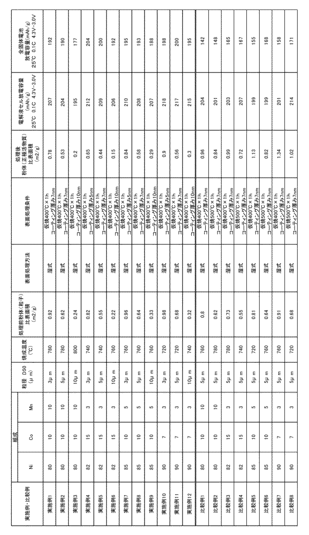
- Comparative Example 7 had a high Ni ratio and a low firing temperature (700 ° C. to 740 ° C., Examples 10 to 12). However, since the sintering was performed at a high temperature of 760 ° C., the relational expression of Y ′ ⁇ 3.5 ⁇ X ′ ⁇ 1 was not satisfied. The comparative examples 3 and 5 also did not satisfy the relational expression of Y ′ ⁇ 3.5 ⁇ X ′ ⁇ 1 due to the same reason.
- Comparative Examples 2, 4, 6, 8 are examples in which wet coating was performed at a temperature higher than that of the examples. Because the temperature was too high, the specific surface area after coating increased. As a result, the battery characteristics as an all-solid-state battery become inferior.
- the description “or” or “or” includes the case where only one of the options is satisfied or the case where all the options are satisfied.
- the description “A or B” and “A or B” it includes both cases where A is satisfied, B is not satisfied, B is satisfied, A is not satisfied, and A is satisfied and B is satisfied. Intended.
Abstract
Description
(1)電極中に固体電解質を3割程度混合する
(2)正極活物質粒子または正極活物質薄膜の界面にLi化合物を被覆する、
(3)より高いリチウムイオン伝導率を有する固体電解質を採用する。
こうしたアプローチにより、従来のリチウムイオン二次電池と同様な安定動作の実現に近づきつつある。
正極活物質であって、
前記正極活物質は、粒子と被覆層とを含み、
前記粒子は以下の組成で表され、
LiaNibCocMndOe
(ここで、
1.0≦a≦1.05、
0.8≦b≦0.9、
1.8≦e≦2.2、
b+c+d=1)
前記被覆層は、LiNbO3で表され、
前記正極活物質の比表面積と粒径が以下の関係を満たす、正極活物質。
Y≦3.5×X-1(X=活物質粒径(μm)、Y=比表面積(m2/g))
(発明2)
発明1に記載の正極活物質であって、前記粒子のD50が2~12μmである、正極活物質。
(発明3)
発明1又は2に記載の正極活物質であって、以下の組成条件を満たす、正極活物質。
0.05≦c≦0.19、
0.01≦d≦0.1
(発明4)
発明1~3いずれか1つに記載の正極活物質であって、前記正極活物質の比表面積が1m2/g以下である、正極活物質。
(発明5)
発明1~4いずれか1つに記載の正極活物質であって、前記正極活物質の比表面積が、前記粒子の比表面積よりも小さい、正極活物質。
(発明6)
発明1~5いずれか1つに記載の正極活物質を製造するための方法であって、
以下の組成の化合物の原料を混合して、700℃~800℃の温度で12~24時間焼成し、焼成体を得る工程と、
LiaNibCocMndOe
(前記式において、
1.0≦a≦1.05、
0.8≦b≦0.9、
1.8≦e≦2.2、
b+c+d=1)
前記焼成体を粉砕して粒子を得る工程と、
前記粒子をLiNbO3で被覆する工程と、
を含み、
前記被覆前の粒子の比表面積よりも、被覆後の正極活物質の比表面積が小さい、該方法。
(発明7)
発明6に記載の方法であって、前記被覆する工程が、
LiNbO3前駆体を含む溶液で被覆すること、及び
前記被覆した粒子に対して、450℃以下で熱処理を行うこと
を含む、該方法。
(発明8)
発明1~5いずれか1つに記載の正極活物質を含むリチウムイオン電池用正極。
(発明9)
発明8のリチウムイオン電池用正極を含むリチウムイオン電池。
本発明は、一実施形態において、ハイニッケル正極活物質に関する。前記ハイニッケル正極活物質は、粒子と、該粒子を被覆する被覆層とを含むことができる。前記粒子は、以下の組成で表されるLi複合化合物であってもよい。
LiaNibCocMndOe
(ここで、
1.0≦a≦1.05、
0.8≦b≦0.9、
1.8≦e≦2.2、
b+c+d=1)
0.05≦c≦0.19、
0.01≦d≦0.1、
更なる一実施形態において、上記組成式中の酸素の存在比eは2であってもよい。
・対象物質を150℃で2時間脱気
・カンタクローム社製のMonosorbにて、吸着ガスとしてHe70at%-N230at%混合ガスを使用し、BET法(1点法)にて測定する。
Y≦3.5×X-1(X=被覆処理後の活物質粒径(μm)、Y=被覆処理後の比表面積(m2/g))
これにより、容量を向上させることができる。上記式中の活物質粒径は、上述したD50と同様の手順で測定した値を指す。上記式中の比表面積は、上述したBET法により測定した値を指す。
Y’≦3.5×X’-1(X’=コア粒子の粒径(μm)、Y’=コア粒子の比表面積(m2/g))
上記式中のコア粒子の粒径は、上述したD50と同様の手順で測定した値を指す。上記式中のコア粒子の比表面積は、上述したBET法により測定した値を指す。
即ち、被覆されていない二次粒子についても、上述した関係を充足することが好ましい。上述した関係を充足すると、被覆後の比表面積を更に減少させることができる(特に後述する湿式被覆方法で被覆した場合)。
被覆前のコア粒子の比表面積Y’>被覆後の活物質の比表面積Y
即ち、被覆処理によって、更に比表面積が小さくなるような関係になることが好ましい。これにより、さらに、放電容量が向上する。
2-1.Li複合化合物粒子の製造方法
本発明の実施形態に係るリチウムイオン電池用正極活物質の製造方法としては、まず、Ni組成がモル比で0.8以上であるNi・Co・Mnの三元系複合水酸化物、又は、Ni・Co・Mnとの三元系複合水酸化物の前駆体を準備する。次に、当該複合水酸化物に、Li源(炭酸Li、水酸化Li等)を、各原料の混合割合を調整してヘンシェルミキサー等で乾式混合した後、700℃~800℃の温度で12~24時間焼成することで、焼成体(正極活物質)を得る。その後、必要であれば、焼成体を、例えば、パルベライザー等を用いて解砕することにより正極活物質の粉体を得る。
一実施形態において、上記粉体は、更にLiNbO3で被覆することができる。被覆方法には、湿式法と乾式法が含まれる。
一実施形態において、本発明における被覆溶液は、ニオブ酸リチウム系化合物の前駆体を含有することができる。ニオブ酸リチウム系化合物の前駆体は、特に限定されるものではないが、後述する熱処理工程によりニオブ酸リチウム系化合物を得ることができるものであればよい。例えば、Li源およびNb源を混合した材料を挙げることができる。Li源としては、例えば、Liアルコキシド等を挙げることができる。Liアルコキシドとしては、例えば、LiOC2H5等を挙げることができる。また、Nb源としては、例えばNbアルコキシド等を挙げることができる。Nbアルコキシドとしては、例えば、Nb(OC2H5)5等を挙げることができる。このようにして作製した溶液を、酸化物正極活物質の表面上に付着させる。溶液の付着方法としては、酸化物正極活物質の表面上に溶液を付着可能な方法であれば特に限定されるものではないが、例えば、転動流動層を有するコート装置を用いる方法や、攪拌・加熱乾燥による方法をとっても良い。
乾式方法による被覆方法として、限定されるものではないが、バレルスパッタ法が挙げられる。一実施形態において、本発明の方法では、LiNbO3ターゲット材を使用し、出力を300~700Wの条件下でバレルスパッタを行うことができる。
このようにして得られたリチウムイオン電池用正極活物質を利用し、公知の手段に従い、リチウムイオン電池用正極を製造することができる。更には、前記正極を用いて、公知の手段に従い、リチウムイオン電池を作製することができる。
正極活物質と、導電材と、バインダーを90:5:5の割合で秤量し、バインダーを有機溶媒(N-メチルピロリドン)に溶解したものに、正極活物質と導電材とを混合してスラリー化し、Al箔上に塗布して乾燥後にプレスして正極とした。続いて、対極をLiとした評価用の2032型コインセルを作製し、電解液に1M-LiPF6をEC-DMC(1:1)に溶解したものを用いて、放電レート0.05Cで得られた初期容量(25℃、充電上限電圧:4.3V、放電下限電圧:3.0V)を測定した。
固体電解質としてLi2S-P2S5(75:25mol%)ガラスセラミックスを使用し、以下の要領でセルを作製した。
(1)正極活物質、電解質、アセチレンブラックを60:35:5の重量比となるように秤量、
(2)上記(1)の合材粉末を乳鉢で混合(全量で約50mg)、
(3)適量の電解質を冶具に入れプレス、
(4)上記(2)で作製した適量の合材を冶具に入れ、プレス、
(5)上部を固定して反転させ下パンチを外す、
(6)負極のLi-In箔を冶具に入れて下部を固定、
(7)加圧ネジで最終固定してシール用袋ナットを締める。
このセルを用いて放電レート0.05Cで得られた初期容量(25℃、充電上限電圧:3.7V、放電下限電圧:2.5V)にて測定した。セルは市販(宝泉製)で販売されているKP-SolidCellとなる。
市販の硫酸ニッケル、硫酸コバルト、硫酸マンガンを水溶液として、Ni、Co、Mnのモル比率が、表1の通りになるように混合し、十分撹拌しながらアルカリ(水酸化ナトリウム)溶液と共沈反応させ、ろ過、洗浄を実施した。反応方法は常法に従って実施した。その後、NiとCoとMnの合計に対するLiのモル比(Li/(Ni+Co+Mn))が1.02となるように、上記共沈反応物を水酸化リチウム1水和物と混合し、ローラーハースキルンで表1の条件で焼成し(焼成時間24時間)、ロールミルとパルべライザーを用いて粒子径(D50)が表1の通りになるように解砕し、コア粒子の粉末(リチウムニッケルコバルトマンガン酸化物)を得た。以降で述べる被覆処理を行う前に、上記BET法により比表面積を測定した。
上記コア粒子の粉末の表面を、LiOC2H5とNb(OC2H5)5を含む溶液で、転動流動層コーティング装置を用いて、コーティングした。その後、表1に記載の条件で、熱処理を行った。なお、被覆層の厚さは最大でも10nmだった。従って、被覆処理によって、μmスケールの粒径サイズに実質的な変化はなかった。従って、被覆前に測定した粒径=被覆後の粒径とみなして、後述する数式「Y≦3.5×X-1」に適用した。
Claims (9)
- 正極活物質であって、
前記正極活物質は、粒子と被覆層とを含み、
前記粒子は以下の組成で表され、
LiaNibCocMndOe
(ここで、
1.0≦a≦1.05、
0.8≦b≦0.9、
1.8≦e≦2.2、
b+c+d=1)
前記被覆層は、LiNbO3で表され、
前記正極活物質の比表面積と粒径が以下の関係を満たす、正極活物質。
Y≦3.5×X-1(X=活物質粒径(μm)、Y=比表面積(m2/g)) - 請求項1に記載の正極活物質であって、前記粒子のD50が2~12μmである、正極活物質。
- 請求項1又は2に記載の正極活物質であって、以下の組成条件を満たす、正極活物質。
0.05≦c≦0.19、
0.01≦d≦0.1 - 請求項1~3いずれか1項に記載の正極活物質であって、前記正極活物質の比表面積が1m2/g以下である、正極活物質。
- 請求項1~4いずれか1項に記載の正極活物質であって、前記正極活物質の比表面積が、前記粒子の比表面積よりも小さい、正極活物質。
- 請求項1~5いずれか1項に記載の正極活物質を製造するための方法であって、
以下の組成の化合物の原料を混合して、700℃~800℃の温度で12~24時間焼成し、焼成体を得る工程と、
LiaNibCocMndOe
(前記式において、
1.0≦a≦1.05、
0.8≦b≦0.9、
1.8≦e≦2.2、
b+c+d=1)
前記焼成体を粉砕して粒子を得る工程と、
前記粒子をLiNbO3で被覆する工程と、
を含み、
前記被覆前の粒子の比表面積よりも、被覆後の正極活物質の比表面積が小さい、該方法。 - 請求項6に記載の方法であって、前記被覆する工程が、
LiNbO3前駆体を含む溶液で被覆すること、及び
前記被覆した粒子に対して、450℃以下で熱処理を行うこと
を含む、該方法。 - 請求項1~5いずれか1項に記載の正極活物質を含むリチウムイオン電池用正極。
- 請求項8のリチウムイオン電池用正極を含むリチウムイオン電池。
Priority Applications (4)
| Application Number | Priority Date | Filing Date | Title |
|---|---|---|---|
| JP2019507879A JP6568333B1 (ja) | 2017-09-28 | 2018-09-12 | 正極活物質、及び、その製造方法、並びに、正極、及びリチウムイオン電池 |
| KR1020197026270A KR20190116999A (ko) | 2017-09-28 | 2018-09-12 | 정극 활물질 및, 그 제조 방법, 그리고 정극 및 리튬 이온 전지 |
| EP18863035.4A EP3584862A4 (en) | 2017-09-28 | 2018-09-12 | POSITIVE ELECTRODE ACTIVE MATERIAL, ITS PRODUCTION PROCESS, POSITIVE ELECTRODE, AND LITHIUM-ION BATTERY |
| CN201880008201.2A CN110235290B (zh) | 2017-09-28 | 2018-09-12 | 正极活性物质及其制造方法、正极以及锂离子电池 |
Applications Claiming Priority (2)
| Application Number | Priority Date | Filing Date | Title |
|---|---|---|---|
| JP2017-188547 | 2017-09-28 | ||
| JP2017188547 | 2017-09-28 |
Publications (1)
| Publication Number | Publication Date |
|---|---|
| WO2019065254A1 true WO2019065254A1 (ja) | 2019-04-04 |
Family
ID=65903166
Family Applications (1)
| Application Number | Title | Priority Date | Filing Date |
|---|---|---|---|
| PCT/JP2018/033869 WO2019065254A1 (ja) | 2017-09-28 | 2018-09-12 | 正極活物質、及び、その製造方法、並びに、正極、及びリチウムイオン電池 |
Country Status (5)
| Country | Link |
|---|---|
| EP (1) | EP3584862A4 (ja) |
| JP (1) | JP6568333B1 (ja) |
| KR (1) | KR20190116999A (ja) |
| CN (1) | CN110235290B (ja) |
| WO (1) | WO2019065254A1 (ja) |
Cited By (4)
| Publication number | Priority date | Publication date | Assignee | Title |
|---|---|---|---|---|
| JP2020047383A (ja) * | 2018-09-14 | 2020-03-26 | Jx金属株式会社 | 正極活物質、及び、その製造方法、並びに、正極、及びリチウムイオン電池 |
| JP2020062632A (ja) * | 2018-10-19 | 2020-04-23 | Jx金属株式会社 | 粉末粒子の被覆方法、全固体リチウムイオン電池用正極活物質の製造方法、全固体リチウムイオン電池の製造方法 |
| WO2020241384A1 (ja) * | 2019-05-31 | 2020-12-03 | 日本ゼオン株式会社 | 二次電池正極用スラリー組成物の製造方法、二次電池用正極の製造方法、及び、二次電池の製造方法 |
| CN113875045A (zh) * | 2019-05-21 | 2021-12-31 | 加拿大商纳诺万麦帝瑞尔公司 | 用于提高电池性能的稳定的高镍nmc阴极材料 |
Citations (7)
| Publication number | Priority date | Publication date | Assignee | Title |
|---|---|---|---|---|
| JPS612859B2 (ja) | 1981-09-28 | 1986-01-28 | Ishikawajima Harima Heavy Ind | |
| JP2007005073A (ja) | 2005-06-22 | 2007-01-11 | Sony Corp | 正極材料および電池、ならびに正極材料の製造方法 |
| JP2010245038A (ja) * | 2009-03-18 | 2010-10-28 | Idemitsu Kosan Co Ltd | 正極合材及びリチウム電池 |
| JP2011065887A (ja) * | 2009-09-17 | 2011-03-31 | Idemitsu Kosan Co Ltd | 正極材料、その製造方法及びリチウムイオン電池 |
| JP4982866B2 (ja) | 2005-07-01 | 2012-07-25 | 独立行政法人物質・材料研究機構 | 全固体リチウム電池 |
| JP2015056307A (ja) * | 2013-09-12 | 2015-03-23 | トヨタ自動車株式会社 | 活物質複合粉体及びリチウム電池並びにその製造方法 |
| JP2017084674A (ja) * | 2015-10-29 | 2017-05-18 | Jx金属株式会社 | リチウムイオン電池用正極活物質、リチウムイオン電池用正極及びリチウムイオン電池 |
Family Cites Families (14)
| Publication number | Priority date | Publication date | Assignee | Title |
|---|---|---|---|---|
| JPS5238194B2 (ja) | 1972-12-14 | 1977-09-27 | ||
| JPS612859A (ja) | 1984-06-15 | 1986-01-08 | 松下電器産業株式会社 | サウナ |
| JP5040073B2 (ja) * | 2005-07-05 | 2012-10-03 | ソニー株式会社 | リチウムイオン二次電池用正極活物質およびその製造方法、並びにリチウムイオン二次電池 |
| CN102769130A (zh) * | 2007-09-04 | 2012-11-07 | 三菱化学株式会社 | 锂过渡金属类化合物粉末 |
| WO2011125722A1 (ja) * | 2010-04-01 | 2011-10-13 | 三菱化学株式会社 | リチウム二次電池用正極材料及びその製造方法、並びにリチウム二次電池用正極及びリチウム二次電池 |
| JP2012238581A (ja) * | 2011-04-28 | 2012-12-06 | Nichia Chem Ind Ltd | 非水電解液二次電池用正極活物質 |
| JP6189649B2 (ja) * | 2013-06-07 | 2017-08-30 | Dowaホールディングス株式会社 | 正極活物質粉末およびその製造法 |
| CN110739451B (zh) * | 2014-01-27 | 2021-05-25 | 住友化学株式会社 | 锂二次电池用正极活性物质、锂二次电池用正极和锂二次电池 |
| JP6090249B2 (ja) * | 2014-07-10 | 2017-03-08 | トヨタ自動車株式会社 | 複合活物質及びその製造方法 |
| KR101796344B1 (ko) * | 2014-09-25 | 2017-11-09 | 주식회사 엘지화학 | 리튬 이차전지용 양극활물질, 이의 제조방법, 및 이를 포함하는 리튬 이차전지 |
| EP3293802B1 (en) * | 2015-09-14 | 2020-10-21 | Toyota Jidosha Kabushiki Kaisha | Method of manufacturing an all-solid-state battery system |
| JP6281545B2 (ja) * | 2015-09-14 | 2018-02-21 | トヨタ自動車株式会社 | 活物質複合粉体の製造方法 |
| JP7013871B2 (ja) * | 2015-10-28 | 2022-02-01 | 住友金属鉱山株式会社 | 非水系電解質二次電池用正極活物質とその製造方法、非水系電解質二次電池用正極合材ペーストおよび非水系電解質二次電池 |
| JP6323475B2 (ja) * | 2016-02-26 | 2018-05-16 | トヨタ自動車株式会社 | 複合活物質、固体電池および複合活物質の製造方法 |
-
2018
- 2018-09-12 CN CN201880008201.2A patent/CN110235290B/zh active Active
- 2018-09-12 EP EP18863035.4A patent/EP3584862A4/en active Pending
- 2018-09-12 KR KR1020197026270A patent/KR20190116999A/ko not_active Application Discontinuation
- 2018-09-12 JP JP2019507879A patent/JP6568333B1/ja active Active
- 2018-09-12 WO PCT/JP2018/033869 patent/WO2019065254A1/ja unknown
Patent Citations (7)
| Publication number | Priority date | Publication date | Assignee | Title |
|---|---|---|---|---|
| JPS612859B2 (ja) | 1981-09-28 | 1986-01-28 | Ishikawajima Harima Heavy Ind | |
| JP2007005073A (ja) | 2005-06-22 | 2007-01-11 | Sony Corp | 正極材料および電池、ならびに正極材料の製造方法 |
| JP4982866B2 (ja) | 2005-07-01 | 2012-07-25 | 独立行政法人物質・材料研究機構 | 全固体リチウム電池 |
| JP2010245038A (ja) * | 2009-03-18 | 2010-10-28 | Idemitsu Kosan Co Ltd | 正極合材及びリチウム電池 |
| JP2011065887A (ja) * | 2009-09-17 | 2011-03-31 | Idemitsu Kosan Co Ltd | 正極材料、その製造方法及びリチウムイオン電池 |
| JP2015056307A (ja) * | 2013-09-12 | 2015-03-23 | トヨタ自動車株式会社 | 活物質複合粉体及びリチウム電池並びにその製造方法 |
| JP2017084674A (ja) * | 2015-10-29 | 2017-05-18 | Jx金属株式会社 | リチウムイオン電池用正極活物質、リチウムイオン電池用正極及びリチウムイオン電池 |
Non-Patent Citations (1)
| Title |
|---|
| See also references of EP3584862A4 |
Cited By (8)
| Publication number | Priority date | Publication date | Assignee | Title |
|---|---|---|---|---|
| JP2020047383A (ja) * | 2018-09-14 | 2020-03-26 | Jx金属株式会社 | 正極活物質、及び、その製造方法、並びに、正極、及びリチウムイオン電池 |
| JP2020062632A (ja) * | 2018-10-19 | 2020-04-23 | Jx金属株式会社 | 粉末粒子の被覆方法、全固体リチウムイオン電池用正極活物質の製造方法、全固体リチウムイオン電池の製造方法 |
| JP7266988B2 (ja) | 2018-10-19 | 2023-05-01 | Jx金属株式会社 | 粉末粒子の被覆方法、全固体リチウムイオン電池用正極活物質の製造方法、全固体リチウムイオン電池の製造方法 |
| CN113875045A (zh) * | 2019-05-21 | 2021-12-31 | 加拿大商纳诺万麦帝瑞尔公司 | 用于提高电池性能的稳定的高镍nmc阴极材料 |
| EP3959762A4 (en) * | 2019-05-21 | 2023-06-07 | Nano One Materials Corp. | STABILIZED HIGH NICKEL NMC CATHODE MATERIALS FOR ENHANCED BATTERY PERFORMANCE |
| WO2020241384A1 (ja) * | 2019-05-31 | 2020-12-03 | 日本ゼオン株式会社 | 二次電池正極用スラリー組成物の製造方法、二次電池用正極の製造方法、及び、二次電池の製造方法 |
| CN113785421A (zh) * | 2019-05-31 | 2021-12-10 | 日本瑞翁株式会社 | 二次电池正极用浆料组合物的制造方法、二次电池用正极的制造方法、以及二次电池的制造方法 |
| US11811065B2 (en) | 2019-05-31 | 2023-11-07 | Zeon Corporation | Method of producing slurry composition for secondary battery positive electrode, method of producing positive electrode for secondary battery, and method of producing secondary battery |
Also Published As
| Publication number | Publication date |
|---|---|
| CN110235290A (zh) | 2019-09-13 |
| EP3584862A4 (en) | 2021-01-13 |
| JPWO2019065254A1 (ja) | 2019-11-14 |
| EP3584862A1 (en) | 2019-12-25 |
| CN110235290B (zh) | 2022-07-29 |
| KR20190116999A (ko) | 2019-10-15 |
| JP6568333B1 (ja) | 2019-08-28 |
Similar Documents
| Publication | Publication Date | Title |
|---|---|---|
| WO2021023313A1 (zh) | 一种双包覆层改性锂离子电池正极材料及其制备方法 | |
| JP6888297B2 (ja) | 非水系電解質二次電池用正極活物質とその製造方法 | |
| JP5742935B2 (ja) | 正極活物質粒子、並びにそれを用いた正極及び全固体電池 | |
| JP2019108264A (ja) | Li−Ni複合酸化物粒子粉末、並びに非水電解質二次電池 | |
| TWI423504B (zh) | A positive electrode active material for a lithium ion battery, a positive electrode for a lithium ion battery, a lithium ion battery, and a method for producing a positive electrode active material for a lithium ion battery | |
| TWI584520B (zh) | Li-Ni composite oxide particles and nonaqueous electrolyte batteries | |
| WO2014181891A1 (ja) | 遷移金属複合水酸化物粒子とその製造方法、非水電解質二次電池用正極活物質とその製造方法および非水電解質二次電池 | |
| JP6533734B2 (ja) | リチウムイオン電池用正極活物質、リチウムイオン電池用正極及びリチウムイオン電池 | |
| EP2911223A1 (en) | Titanium-niobium composite oxide-based electrode active material and lithium secondary battery using the same | |
| WO2012029697A1 (ja) | チタン酸リチウム粒子粉末及びその製造方法、Mg含有チタン酸リチウム粒子粉末及びその製造法、非水電解質二次電池用負極活物質粒子粉末並びに非水電解質二次電池 | |
| JP6568333B1 (ja) | 正極活物質、及び、その製造方法、並びに、正極、及びリチウムイオン電池 | |
| WO2018052038A1 (ja) | 非水系電解質二次電池用正極活物質とその製造方法、および該正極活物質を用いた非水系電解質二次電池 | |
| JP7292574B2 (ja) | リチウムイオン二次電池用正極活物質とその製造方法、およびリチウムイオン二次電池 | |
| JP2009252421A (ja) | 負極活物質およびその製造方法ならびに該負極活物質を備えた電池 | |
| JP2022115903A (ja) | 遷移金属含有複合水酸化物粒子とその製造方法、非水電解質二次電池用正極活物質とその製造方法、および非水電解質二次電池 | |
| US20130105730A1 (en) | Lithium-titanium complex oxide, and battery electrode and lithium ion secondary battery using same | |
| JP2020177860A (ja) | ニッケルマンガンコバルト含有複合水酸化物およびその製造方法、リチウムニッケルマンガンコバルト含有複合酸化物およびその製造方法、リチウムイオン二次電池用正極活物質およびその製造方法、並びに、リチウムイオン二次電池 | |
| JP2019139862A (ja) | リチウムイオン電池用正極活物質、リチウムイオン電池用正極活物質の製造方法、リチウムイオン電池用正極及びリチウムイオン電池 | |
| WO2016017360A1 (ja) | 非水系電解質二次電池用の正極活物質及びその製造方法、並びに非水系電解質二次電池 | |
| CN114521300A (zh) | 锂离子二次电池用正极活性物质以及锂离子二次电池 | |
| JP7172301B2 (ja) | 遷移金属複合水酸化物、遷移金属複合水酸化物の製造方法、リチウム遷移金属複合酸化物活物質及びリチウムイオン二次電池 | |
| KR102086100B1 (ko) | 금속이 코팅된 리튬 이차 전지용 양극활물질의 제조방법 및 이의 의하여 제조된 리튬 이차 전지용 양극활물질 | |
| JP2023539302A (ja) | 正極及び電気化学装置 | |
| JP2022179554A (ja) | リチウム化合物 | |
| JP7271945B2 (ja) | リチウムイオン二次電池用正極活物質とその製造方法、およびリチウムイオン二次電池 |
Legal Events
| Date | Code | Title | Description |
|---|---|---|---|
| ENP | Entry into the national phase |
Ref document number: 2019507879 Country of ref document: JP Kind code of ref document: A |
|
| 121 | Ep: the epo has been informed by wipo that ep was designated in this application |
Ref document number: 18863035 Country of ref document: EP Kind code of ref document: A1 |
|
| ENP | Entry into the national phase |
Ref document number: 20197026270 Country of ref document: KR Kind code of ref document: A |
|
| ENP | Entry into the national phase |
Ref document number: 2018863035 Country of ref document: EP Effective date: 20190920 |
|
| NENP | Non-entry into the national phase |
Ref country code: DE |