WO2017056680A1 - 放射線画像取得システムおよび放射線画像取得方法 - Google Patents
放射線画像取得システムおよび放射線画像取得方法 Download PDFInfo
- Publication number
- WO2017056680A1 WO2017056680A1 PCT/JP2016/072441 JP2016072441W WO2017056680A1 WO 2017056680 A1 WO2017056680 A1 WO 2017056680A1 JP 2016072441 W JP2016072441 W JP 2016072441W WO 2017056680 A1 WO2017056680 A1 WO 2017056680A1
- Authority
- WO
- WIPO (PCT)
- Prior art keywords
- radiation
- scintillator
- image
- image acquisition
- radiographic image
- Prior art date
- Legal status (The legal status is an assumption and is not a legal conclusion. Google has not performed a legal analysis and makes no representation as to the accuracy of the status listed.)
- Ceased
Links
Images



Classifications
-
- G—PHYSICS
- G01—MEASURING; TESTING
- G01T—MEASUREMENT OF NUCLEAR OR X-RADIATION
- G01T1/00—Measuring X-radiation, gamma radiation, corpuscular radiation, or cosmic radiation
- G01T1/16—Measuring radiation intensity
- G01T1/20—Measuring radiation intensity with scintillation detectors
-
- G—PHYSICS
- G01—MEASURING; TESTING
- G01N—INVESTIGATING OR ANALYSING MATERIALS BY DETERMINING THEIR CHEMICAL OR PHYSICAL PROPERTIES
- G01N23/00—Investigating or analysing materials by the use of wave or particle radiation, e.g. X-rays or neutrons, not covered by groups G01N3/00 – G01N17/00, G01N21/00 or G01N22/00
- G01N23/02—Investigating or analysing materials by the use of wave or particle radiation, e.g. X-rays or neutrons, not covered by groups G01N3/00 – G01N17/00, G01N21/00 or G01N22/00 by transmitting the radiation through the material
- G01N23/04—Investigating or analysing materials by the use of wave or particle radiation, e.g. X-rays or neutrons, not covered by groups G01N3/00 – G01N17/00, G01N21/00 or G01N22/00 by transmitting the radiation through the material and forming images of the material
-
- G—PHYSICS
- G01—MEASURING; TESTING
- G01T—MEASUREMENT OF NUCLEAR OR X-RADIATION
- G01T7/00—Details of radiation-measuring instruments
- G01T7/08—Means for conveying samples received
-
- G—PHYSICS
- G06—COMPUTING OR CALCULATING; COUNTING
- G06T—IMAGE DATA PROCESSING OR GENERATION, IN GENERAL
- G06T5/00—Image enhancement or restoration
- G06T5/90—Dynamic range modification of images or parts thereof
- G06T5/92—Dynamic range modification of images or parts thereof based on global image properties
-
- G—PHYSICS
- G06—COMPUTING OR CALCULATING; COUNTING
- G06T—IMAGE DATA PROCESSING OR GENERATION, IN GENERAL
- G06T2207/00—Indexing scheme for image analysis or image enhancement
- G06T2207/10—Image acquisition modality
- G06T2207/10116—X-ray image
Definitions
- the present disclosure relates to a radiation image acquisition system and a radiation image acquisition method.
- an X-ray inspection apparatus including a fluorescent plate that converts X-rays irradiated from an X-ray generation source and transmitted through an inspection object into light, and a CCD camera that images the fluorescent plate.
- a fluorescent plate comprising a front fluorescent plate positioned on the X-ray irradiation surface, a rear fluorescent plate positioned on the back side thereof, and a metal filter positioned therebetween is used.
- the CCD camera is composed of a high energy CCD camera and a low energy CCD camera. X-rays that have passed through the object to be inspected are converted into scintillation light in the front fluorescent plate and the rear fluorescent plate, and imaged by the two CCD cameras.
- the present inventors have developed a radiation image acquisition system to which a so-called scintillator double-sided observation system (DSSD) is applied.
- DSSD scintillator double-sided observation system
- scintillation light output from the front surface of the scintillator is imaged by a low energy camera
- scintillation light output from the back surface of the scintillator is imaged by a high energy camera.
- This disclosure describes a radiation image acquisition system and a radiation image acquisition method capable of acquiring a clear radiation image.
- One aspect of the present disclosure is a radiation image acquisition system that acquires a radiation image of an object.
- a radiation source that outputs radiation toward the object, and radiation that is output from the radiation source and transmitted through the object are input.
- a scintillator that has an input surface and converts radiation input to the input surface into scintillation light, and a scintillator that is opaque to the scintillation light, and a lens that focuses the input surface and images the scintillation light output from the input surface
- An imaging unit that images the scintillation light imaged by the lens unit, an imaging unit that outputs radiographic image data of the target, and an object based on the radiographic image data output from the imaging unit
- a step of outputting radiation from a radiation source toward the target (radiation output step), and radiation transmitted through the target are input
- a scintillator that has an input surface that is opaque to the scintillation light
- converts the radiation input to the input surface into a scintillation light conversion step
- uses a lens unit that focuses on the input surface.
- Imaging the scintillation light output from the surface onto the imaging unit imaging unit
- imaging the scintillation light imaged by the lens unit using the imaging unit
- the scintillation light output from the input surface of the scintillator is imaged on the imaging unit by the lens unit focused on the input surface.
- the radiographic image data of a target object is output, and the radiographic image of a target object is created based on this radiographic image data.
- an opaque scintillator is used for conversion from radiation to scintillation light.
- scintillation light output from the input surface of the scintillator is imaged.
- the outline of the object and the characters or patterns printed thereon can be identified from the image.
- the object composed of a substance having the same radiation transmittance may be an object composed of a substance having a slightly different radiation transmittance, such as plastics and ink.
- An object having a portion made of a material having the same radiation transmittance and having a different thickness, such as plastics, may be used.
- the lens unit is disposed so as to face the input surface.
- scintillation light output from the input surface can be imaged with a simple configuration.
- the radiation image acquisition system further includes a transport device that is disposed between the radiation source and the scintillator and transports the object in the transport direction.
- a transport device that is disposed between the radiation source and the scintillator and transports the object in the transport direction.
- a radiation image can be acquired at a higher speed.
- an area sensor camera may be used to turn on the radiation source in accordance with the imaging timing.
- the imaging unit is an area image sensor capable of time delay integration (TDI) drive, and is synchronized with the movement of the object by the transport device on the light receiving surface. Charge transfer is performed. In this case, a radiographic image with a good S / N ratio can be acquired.
- TDI time delay integration
- the tube voltage of the radiation source can be adjusted within a range of 10 kV to 300 kV, and the thickness of the scintillator is within a range of 10 ⁇ m to 1000 ⁇ m.
- the tube voltage of the radiation source can be adjusted within a range of 150 kV to 1000 kV, and the thickness of the scintillator is within a range of 100 ⁇ m to 50000 ⁇ m.
- the image creation unit creates the radiation image of the object based on at least a lookup table for contrast conversion corresponding to the thickness of the scintillator. In this case, even if the contrast of the radiographic image obtained by imaging the input surface changes according to the thickness of the scintillator, the contrast can be appropriately converted.
- the radiation source outputs radiation containing characteristic X-rays of 20 keV or less, and the radiation transmitted through the object and converted by the scintillator includes characteristic X-rays of 20 keV or less.
- the method further includes a step of transporting the object in the transport direction (transport step) using a transport device disposed between the radiation source and the scintillator.
- a transport device disposed between the radiation source and the scintillator.
- a line scan camera for example, by using a line scan camera and performing imaging in accordance with the conveyance speed of the object, a radiation image can be acquired at a higher speed.
- an area sensor camera may be used to turn on the radiation source in accordance with the imaging timing.
- the imaging unit is an area image sensor capable of time-delay integration driving.
- the light receiving surface of the area image sensor is synchronized with the movement of the object by the transport device. Charge transfer is performed. In this case, a radiographic image with a good S / N ratio can be acquired.
- the thickness of the scintillator is in the range of 10 ⁇ m to 1000 ⁇ m, and in the radiation output step, the tube voltage of the radiation source is in the range of 10 kV to 300 kV.
- the thickness of the scintillator is in the range of 100 ⁇ m to 50000 ⁇ m, and in the radiation output step, the tube voltage of the radiation source is in the range of 150 kV to 1000 kV.
- a radiation image of the object is created based on at least a lookup table for contrast conversion corresponding to the thickness of the scintillator. In this case, even if the contrast of the radiographic image obtained by imaging the input surface changes according to the thickness of the scintillator, the contrast can be appropriately converted.
- the radiation output step outputs radiation containing characteristic X-rays of 20 keV or less
- the conversion step scintillates radiation that passes through the object and contains characteristic X-rays of 20 keV or less. Convert to light.
- a clear radiation image can be acquired.
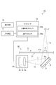
- FIG. 1 is a diagram illustrating a schematic configuration of a radiological image acquisition apparatus according to the first embodiment of the present disclosure.
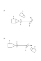
- FIG. 2 is a diagram illustrating a schematic configuration of a radiological image acquisition apparatus according to the second embodiment of the present disclosure.
- FIG. 3A is a diagram showing the arrangement of the imaging means according to the embodiment, and
- FIG. 3B is a diagram showing the arrangement of the imaging means according to the comparative example.
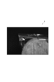
- FIG. 4 is a photograph showing a plastic food packaging as an object.
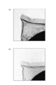
- FIG. 5A is a diagram showing a radiographic image according to the first example
- FIG. 5B is a diagram showing a radiographic image according to the first comparative example.
- FIG. 6A is a diagram showing a radiographic image according to the second embodiment, and FIG.
- FIG. 6B is a diagram showing a radiographic image according to the second comparative example.
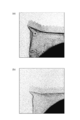
- FIG. 7A is a diagram showing a radiographic image according to the third embodiment
- FIG. 7B is a diagram showing a radiographic image according to the third comparative example.
- FIG. 8A is a diagram showing a radiographic image according to the fourth example
- FIG. 8B is a diagram showing a radiographic image according to the fourth comparative example.
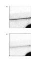
- FIG. 9A shows a radiographic image according to the fifth comparative example
- FIG. 9B shows a radiographic image according to the sixth comparative example.
- FIG. 10A is a diagram showing an X-ray energy spectrum used in the simulation
- FIG. 10B is a diagram showing a simulation result performed with an X-ray energy spectrum before correction
- FIG. 10C is a graph after correction. It is a figure which shows the simulation result performed with the X-ray energy spectrum.
- the radiological image acquisition system 1 is an apparatus for acquiring a radiographic image of the object A.
- the object A has, for example, a composition composed of light elements.
- the composition of the object A is not limited to this.
- the object A may be an object composed of a material having a slightly different radiation transmittance.
- Such objects include, for example, plastics or films printed with ink, foods containing foreign matters such as parasites and hair, voids and bubbles contained in light elemental substances such as resins, carbon fibers and engineering.
- the internal structure of composite materials such as plastic, and the internal structure of paint.
- the object A may be an object that is formed of a material having the same radiation transmittance and has portions with different thicknesses. Examples of such objects include pressed plastics and watermarked papers, semiconductor devices made by microfabrication, separators and electrodes that are components of batteries, and peripheral structures thereof.
- the object A may be made of a substance having a similar radiation transmittance, which is difficult to identify in a conventional radiographic image.
- Such an object A has not been taken as an imaging target in the conventional radiation image acquisition system.
- the radiological image acquisition system 1 acquires a radiographic image having a contrast even if the object A has a composition composed of light elements or is made of a substance having a similar radiation transmittance. Is possible.
- the outline of the object A as described above, characters or patterns printed on the object A, and the like can be identified from the image.
- the radiation image acquisition system 1 generates a scintillation light in response to a radiation source 2 that outputs radiation such as white X-rays toward the object A and radiation input from the radiation source 2 and transmitted through the object A.
- the scintillator 6 to be controlled, the camera (imaging means) 3 that images the scintillation light output from the radiation input surface 6a of the scintillator 6, and some functions of the radiation image acquisition system 1 are controlled and a radiation image is created.
- a computer 10 The radiation image acquisition system 1 further includes an object holding unit 7 that holds the object A and a scintillator holding unit 8 that holds the scintillator 6.
- the radiation source 2, the camera 3, the object holding unit 7, and the scintillator holding unit 8 are housed in a housing (not shown) and fixed in the housing. All or at least one of the radiation source 2, the camera 3, the object holding unit 7, and the scintillator holding unit 8 may be movable so that the relative positional relationship with each other can be adjusted.
- the computer 10 may be housed in a housing or installed outside the housing. A display device (display unit) 16 and an input device (input unit) 17 are connected to the computer 10.
- the radiation source 2 which is a light source emits (outputs) X-rays irradiated on the object A.
- the radiation source 2 emits (outputs) cone beam X-rays from an X-ray emission point.
- X-rays emitted from the radiation source 2 form a radiation bundle 12.
- An area where the radiation bundle 12 exists is an emission area of the radiation source 2.
- the radiation source 2 outputs radiation including characteristic X-rays (fluorescent X-rays) of 20 keV or less.
- the radiation source 2 may output radiation including characteristic X-rays of 10 to 20 keV.
- the radiation source 2 may output radiation including soft X-rays.
- the radiation source 2 is configured so that the tube voltage and the tube current can be adjusted.
- the tube voltage at the radiation source 2 can be adjusted between at least 10 kV and 1000 kV.
- the tube current in the radiation source 2 can be adjusted between at least 10 ⁇ A and 500 mA.
- Characteristic X-rays below 20 keV can vary depending on the target material of the source. For example, tungsten (W) includes L-line characteristic X-rays (9.8 keV), and molybdenum (Mo) includes K-line characteristic X-rays (17.4 keV).
- the radiation source 2 is disposed so that the optical axis of the radiation forms a predetermined angle with respect to the normal line of the input surface 6 a of the scintillator 6. That is, the radiation source 2 faces the object A and the input surface 6a and is disposed at a position deviating from the normal line of the input surface 6a. In other words, the radiation source 2 is arranged so that the angle formed between the optical axis and the input surface 6a is larger than 0 degree and smaller than 90 degrees. In addition, the radiation source 2 may be arrange
- the object holding unit 7 is disposed between the radiation source 2 and the scintillator holding unit 8.
- the object holding unit 7 holds the object A in a state where the object A is positioned at least in the radiation bundle 12.
- the object holding unit 7 holds the object A on the side facing the radiation source 2. It is preferable that a filter or the like for reducing radiation including characteristic X-rays (fluorescent X-rays) of 20 keV or less is not disposed between the object A and the radiation source 2. Thereby, the object A can be irradiated with radiation including characteristic X-rays (fluorescent X-rays) of 20 keV or less.
- the object holding unit 7 is provided so that the influence on the radiation transmitted through the object A is reduced (minimized).
- the object holding unit 7 may be made of a low-element material such as a carbon fiber such as carbon, a plastic, a film, or a thin film containing a metal. Further, an opening smaller than the object A may be provided in the object holding part 7 so that the object holding part 7 does not enter the observation field of view. When the object A is held by the object holding unit 7, the holding unit may be placed outside the observation field. Further, the object A and the object holding unit 7 may be arranged so that the object A and the object holding unit 7 do not overlap on the image.
- the scintillator 6 is a plate (for example, flat plate) wavelength conversion member.
- the scintillator 6 has an input surface 6a to which the radiation transmitted through the object A is input.
- the input surface 6 a is a front surface (front surface) facing the radiation source 2.
- the input surface 6a is an observation surface in the radiation image acquisition system 1.
- the radiation image acquisition system 1 uses the input surface 6a of the scintillator 6 as an observation surface.
- the scintillator 6 converts the radiation transmitted through the object A and input to the input surface 6a into scintillation light.
- the scintillator 6 converts radiation containing characteristic X-rays of 20 keV or less that is transmitted through the object A and input to the input surface 6a into scintillation light.
- the radiation with relatively low energy is converted on the input surface 6a side and emitted (output) from the input surface 6a. Since the radiation of relatively high energy is converted on the back surface of the scintillator 6, it is difficult for the radiation to be emitted from the input surface 6a. Therefore, in the radiation image acquisition system 1 using the input surface 6a as the observation surface, scintillation light converted from radiation having a relatively low energy is used to create a radiation image.
- the scintillator 6 is a scintillator that is opaque to the scintillation light.
- the scintillator 6 is, for example, a scintillator in which a fluorescent material is vapor-deposited or coated, deposited, or crystal-grown on a support, or a scintillator in which a fluorescent material is contained in a plastic container.
- the scintillator 6 is, for example, a granular scintillator or a columnar scintillator.
- the thickness of the scintillator 6 is set to an appropriate value in the range of several ⁇ m to several cm. Particularly in this embodiment, the thickness of the scintillator 6 is set to an appropriate value based on the tube voltage of the radiation source 2. The thickness of the scintillator 6 may be set to an appropriate value based on the energy band of the detected radiation. The thickness of the scintillator 6 may be set to an appropriate value based on the composition or thickness of the object A.
- the thickness of the scintillator 6 is in the range of 10 ⁇ m to 50000 ⁇ m.
- the thickness of the scintillator 6 is set to a value within the range of 10 ⁇ m to 1000 ⁇ m.
- the thickness of the scintillator 6 is set to a value within the range of 100 ⁇ m to 50000 ⁇ m.
- a scintillator that is opaque to the scintillation light is a scintillator in which the light transmittance of the scintillator at the wavelength of the scintillation light is 80% or less by scattering or absorbing the scintillation light inside the scintillator.
- the amount of light output from the back surface 6b of the scintillator 6 becomes 80% or less of the input light amount.
- the light transmittance of the scintillator 6 may be within a range of 0% to 60% at a thickness of 1000 ⁇ m (1 mm), for example (scintillation light wavelength: 550 nm).
- the object A made of a material having the same radiation transmittance particularly for the object A made of a light element
- Usefulness of front surface observation is demonstrated.
- the scintillator holding unit 8 holds the scintillator 6 in a state where the scintillator 6 is at least in the radiation bundle 12.
- the scintillator holding unit 8 holds the back surface side of the scintillator 6 and exposes the input surface 6 a of the scintillator 6.
- the input surface 6 a faces the radiation source 2 and faces the camera 3.
- the scintillator holding unit 8 is configured to be able to replace the held scintillator 6 so that scintillators 6 having different thicknesses and types can be selected in accordance with the tube voltage of the radiation source 2 to be used.
- the scintillator holding part 8 can change the size (length, width, height) and shape of the part to which the scintillator 6 is attached.
- the scintillator holding part 8 may have a light shielding property. Further, the scintillator holding part 8 is preferably provided with an anti-reflection measure, but may be reflected.
- the camera 3 is an indirect conversion type imaging unit that images a projection image (that is, a radiation transmission image) of the object A projected on the scintillator 6 from the input surface 6 a side of the scintillator 6. That is, the camera 3 is an imaging unit on the input surface 6a side.
- the camera 3 includes a lens (lens unit) 3a that images the scintillation light output from the input surface 6a of the scintillator 6, and an image sensor (imaging unit) 3b that images the scintillation light imaged by the lens 3a.
- the camera 3 may be a lens coupling type photodetector.
- the camera 3 is arranged on the side facing the input surface 6a with the scintillator holding portion 8 as a reference.
- the camera 3 may be disposed so as to face the input surface 6 a of the scintillator 6.
- at least the lens 3a is disposed so as to face the input surface 6a, and the input surface 6a and the image sensor 3b are optically coupled by the lens 3a.
- the camera 3 may be arranged so that the scintillation light can be imaged through a mirror (not shown) that reflects the scintillation light emitted from the input surface 6 a of the scintillator 6.
- the input surface 6a and the image sensor 3b are optically coupled by the mirror and the lens 3a.
- the lens 3a collects the scintillation light in the visual field 13.
- the lens 3 a is arranged so that the focal point is focused on the input surface 6 a of the scintillator 6. Therefore, the scintillation light converted relatively on the input surface 6a side of the scintillator 6 can be collected.
- the lens 3a collects the scintillation light output from the input surface 6a and forms an image on the light receiving surface 3c of the image sensor 3b.
- the image sensor 3b receives the scintillation light imaged by the lens 3a and performs photoelectric conversion.
- the image sensor 3 b is electrically connected to the computer 10.
- the camera 3 outputs the radiation image data obtained by the imaging to the image processor 10a of the computer 10.
- an area image sensor such as a CCD area image sensor or a CMOS area image sensor is used as the image sensor 3b.
- the camera 3 is arranged so that the optical axis L of the lens 3a is orthogonal to the input surface 6a. That is, the lens 3a of the camera 3 faces the input surface 6a and is disposed on the normal line of the input surface 6a.
- the camera 3 is arranged off the optical axis of the radiation source 2. That is, the camera 3 is disposed so as to be separated from the radiation emission region (region where the radiation bundle 12 exists) from the radiation source 2. As a result, exposure of the camera 3 due to radiation from the radiation source 2 is prevented, and generation of noise due to the direct conversion signal of radiation within the camera 3 is prevented.
- the lens 3a of the camera 3 is disposed so that a perpendicular line dropped from the center of the lens 3a to the input surface 6a of the scintillator 6 is within the range of the input surface 6a, and is disposed above the input surface 6a of the scintillator 6. Yes. Thereby, a relatively large amount of scintillation light can be detected.
- a mirror or the like can be provided at a position facing the scintillator 6 and the optical path of the scintillation light can be changed as appropriate.
- the camera 3 since the camera 3 does not have to be disposed so as to face the input surface 6a of the scintillator 6, the camera 3 is on the side opposite to the input surface 6a with respect to the scintillator holding portion 8, that is, the radiation source 2. May be arranged on the opposite side.
- One or a plurality of mirrors may be provided as an optical element for guiding the scintillation light to an appropriate optical path.
- the radiation source 2 and the camera 3 may be provided at a position where they do not interfere with each other (or a position where there is little interference) in relation to the object holding unit 7 (object A) and the scintillator holding unit 8 (scintillator 6).
- the radiation source 2 and the camera 3 may be arranged on a plane including the normal line of the input surface 6a of the scintillator 6, but may be appropriately arranged three-dimensionally around the normal line of the input surface 6a.
- the computer 10 includes a computer having a CPU (Central Processing Unit), a ROM (Read Only Memory), a RAM (Random Access Memory), an input / output interface, and the like.
- the computer 10 is based on the radiation image data output from the camera 3, and an image processor (image creation unit) 10 a that creates a radiation image of the object A, and a control processor (control) that controls the radiation source 2 and the camera 3. Part) 10b.
- the image processor 10a inputs radiation image data, and executes predetermined processing such as image processing on the input radiation image data.
- the image processor 10 a outputs the created radiation image to the display device 16.
- the control processor 10b controls the radiation source 2 based on the tube voltage and tube current value of the radiation source 2 stored by the user's input or the like.
- the control processor 10b controls the camera 3 based on the exposure time and the like of the camera 3 stored by user input or the like.
- the image processor 10a and the control processor 10b may be separate processors or the same processor.
- the computer 10 may be programmed so as to execute the functions of the image processor 10a and the functions of the control processor.
- the display device 16 is a display that displays a radiation image.
- a known display may be used as the display device 16.
- the display device 16 displays the radiation image output from the image processor 10a.
- the input device 17 is, for example, a keyboard or a mouse. The user can input various parameters such as the tube voltage and tube current values of the radiation source 2 or the exposure time of the camera 3 using the input device 17. Various parameters input by the input device 17 are stored in the computer 10.
- the object A is prepared, and the object A is held by the object holding unit 7.
- parameters such as the tube voltage and tube current values of the radiation source 2 and the exposure time of the camera 3 are input in advance using the input device 17 (Parmeter input step).
- a scintillator 6 is selected.
- the thickness and type of the scintillator 6 are determined, and the scintillator 6 is held by the scintillator holding portion 8. The determined thickness and type of the scintillator 6 are input using the input device 17 (scintillator selection step).
- the scintillator 6, the radiation source 2, and the camera 3 are adjusted with respect to the scintillator holding unit 8 and positioned.
- the camera 3 is provided so that the optical axis L of the lens 3a of the camera 3 intersects the input surface 6a.
- the focal position of the lens 3a of the camera 3 is adjusted to the input surface 6a.
- the thickness of the scintillator 6 may be in the range of 10 ⁇ m to 1000 ⁇ m.
- the tube voltage of the radiation source 2 may be in the range of 10 kV to 300 kV.
- the thickness of the scintillator 6 may be in the range of 100 ⁇ m to 50000 ⁇ m.
- the tube voltage of the radiation source 2 may be in the range of 150 kV to 1000 kV.
- parameters such as the tube voltage of the radiation source 2 may be set in accordance with the scintillator 6.
- the process proceeds to irradiation of the radiation source 2 and observation of the input surface 6a (front surface) by the camera 3.
- the following operations and processes are controlled by the control processor 10b of the computer 10.
- Radiation such as white X-rays is output (irradiated) from the radiation source 2 toward the object A (radiation output step).
- the radiation irradiated to the object A is preferably radiation including characteristic X-rays of 20 keV or less.
- the radiation that passes through the object A and reaches the scintillator 6 can include characteristic X-rays of 20 keV or less.
- the radiation that has passed through the object A is input to the input surface 6a, and the scintillator 6 converts the radiation into scintillation light (conversion step).
- the scintillation light output from the input surface 6a is imaged on the image sensor 3b by the lens 3a of the camera 3 (imaging process).
- the image sensor 3b captures scintillation light (scintillation image) formed by the lens 3a.
- the camera 3 outputs the radiation image data obtained by imaging to the image processor 10a of the computer 10 (imaging process).
- the image processing processor 10a of the computer 10 inputs radiation image data, executes predetermined processing such as image processing on the input radiation image data, and creates a radiation image (image creation step). More specifically, the image processor 10a performs contrast conversion corresponding to the input parameters (the values of the tube voltage and tube current of the radiation source 2, the exposure time of the camera 3, the thickness and type of the scintillator 6). A LUT (lookup table) is determined, and a radiation image is created based on the input radiation image data.
- the computer 10 may store a plurality of LUTs corresponding to a plurality of parameters, and may select an LUT corresponding to the input parameter from among them, or the computer 10 creates an LUT based on the input parameter. May be.
- the user may input an LUT corresponding to the parameter.
- the inventors have confirmed that the contrast of a radiographic image obtained by front surface imaging changes depending on the thickness of the scintillator. Therefore, the image processor 10a can acquire a radiographic image having an appropriate contrast by creating a radiographic image of the object based on at least a contrast conversion LUT corresponding to the thickness of the scintillator.
- the image processor 10 a outputs the created radiation image to the display device 16.
- the display device 16 displays the radiation image output from the image processor 10a.
- a radiographic image is obtained by observing the front surface of the object A.
- the radiographic image acquired by the radiographic image acquisition system 1 is for an object A composed of a substance having a similar radiation transmittance, such as a plastic on which characters and patterns are printed, a pressed plastic, or the like.
- the shape (outside shape, etc.) of the object A and the printed pattern can be clearly identified.
- the shape (outside shape, etc.) of the object A can be clearly identified even with respect to the object A made of a light element such as plastic.
- even a slight difference in thickness of the same material is reflected in the radiation image, and fine unevenness processing on the object A, characters or patterns printed on the object A, and the like can be identified.
- the opaque scintillator 6 is used for conversion from radiation to scintillation light.
- the scintillation light output from the input surface 6a of the scintillator 6 is imaged.
- the lens 3a is disposed so as to face the input surface 6a. Therefore, the scintillation light output from the input surface 6a can be imaged with a simple configuration.
- the image processor 10a creates a radiographic image of the object A based on the LUT for contrast conversion corresponding to at least the thickness of the scintillator 6. Therefore, even if the contrast of the radiographic image obtained by imaging the front surface changes according to the thickness of the scintillator 6, the contrast can be appropriately converted.
- a radiographic image acquisition system 1A is different from the radiographic image acquisition system 1 of the first embodiment in that the target object A is replaced by a predetermined transport direction instead of the target object holding unit 7 that holds the target object A in a stationary state. And a point provided with a camera 3 ⁇ / b> A which is a line scan camera instead of the camera 3.
- the transport device 20 includes a belt conveyor 21 that moves on a circular path, and the object A is placed or held on the belt conveyor 21.
- the transport device 20 includes a drive source (not shown) that drives the belt conveyor 21.
- the belt conveyor 21 of the transport device 20 is disposed between the radiation source 2 and the scintillator holding unit 8 (scintillator 6).
- the transport device 20 is configured to transport the object A in the transport direction D at a constant speed.
- the conveyance timing and conveyance speed of the object A in the conveyance device 20 are set in advance and are controlled by the control processor 10 b of the computer 10.
- the camera 3A is a line scan camera and takes an image in accordance with the movement of the object A.
- the camera 3A includes a line sensor or an area image sensor capable of TDI (time delay integration) driving as the image sensor 3b.
- the image sensor 3b is controlled by the control processor 10b to perform charge transfer in accordance with the movement of the object A. That is, the image sensor 3 b performs charge transfer on the light receiving surface 3 c in synchronization with the movement of the object A by the transport device 20. Thereby, a radiographic image with a good S / N ratio can be obtained.
- the control processor 10b of the computer 10 controls the radiation source 2 and the camera 3A to turn on the radiation source 2 in accordance with the imaging timing of the camera 3A. May be.
- the scintillator 6 is arranged such that its input surface 6a is inclined at a predetermined angle (for example, 45 °) with respect to the optical axis L of the lens 3a of the camera 3A.
- the input surface 6a of the scintillator 6 is arranged so as to be inclined at a predetermined angle (for example, 45 °) with respect to the optical axis of the radiation source 2.
- the camera 3A can be compactly arranged without causing physical interference with the belt conveyor 21 of the transport device 20.
- the input surface 6a and the image sensor 3b are optically coupled by the lens 3a.
- the present invention is not limited to this configuration, and the camera 3A may be arranged so as to capture the scintillation light through a mirror (not shown) that reflects the scintillation light emitted from the input surface 6a of the scintillator 6.
- the input surface 6a and the image sensor 3b are optically coupled by the mirror and the lens 3a.
- the radiological image acquisition method by the radiological image acquisition system 1A is basically the same as the radiological image acquisition method by the radiological image acquisition system 1 described above, but transports the object A using the transport device 20 in the radiation output step. The difference is that a process is provided, and charge transfer (TDI operation) is performed in synchronization with the movement of the object A in the imaging process.
- TDI operation charge transfer
- a radiation image can be acquired at a higher speed. Moreover, a radiographic image with a good S / N ratio can be acquired.
- FIG. 4 a radiation image of a bag (a container for food packaging) made of polyethylene was examined as one sample of the object A made of a light element.
- This bag is transparent, and one side of the bag has a jagged shape (zigzag shape). Characters are printed (printed) on the end of the bag.
- the bag contains contents such as food.
- the input surface 6a was observed (front surface photographing).
- the back surface 6b was observed (back surface photography).
- the apparatus configuration used for the front surface photographing is the same as that of the radiological image acquisition system 1 of the first embodiment, and a form in which the object A is held and stopped and an area image sensor is used is adopted. Except for the fifth and sixth comparative examples, an opaque scintillator 6 was used as the scintillator.
- the input surface 6a was observed (front surface photographing) while using a transparent scintillator.
- the back surface 6b was observed (back surface imaging) while using a transparent scintillator.
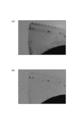
- FIG. 5A is a diagram showing a radiographic image according to the first example
- FIG. 5B is a diagram showing a radiographic image according to the first comparative example.
- the photographing surfaces were reversed, and photographing was performed with different exposure times.
- the radiation source a radiation source capable of outputting radiation including characteristic X-rays of 20 keV or less was used.
- the scintillator an opaque GOS sheet having a thickness of 85 ⁇ m was used.
- the tube voltage of the radiation source was 40 kV in all cases.
- the tube current of the radiation source was 200 ⁇ A in all cases.
- the exposure time was 2 seconds for imaging the front surface and 10 seconds for imaging the back surface. Further, no filter for reducing radiation is disposed between the radiation source and the scintillator.
- FIG. 6A is a diagram showing a radiographic image according to the second embodiment
- FIG. 6B is a diagram showing a radiographic image according to the second comparative example.
- the photographing was performed under the same photographing conditions except that the photographing surface was reversed and the exposure time was changed.
- the radiation source a radiation source capable of outputting radiation including characteristic X-rays of 20 keV or less was used.
- the scintillator an opaque GOS sheet having a thickness of 85 ⁇ m was used.
- the tube voltage of the radiation source was 100 kV in all cases.
- the tube current of the radiation source was 200 ⁇ A in all cases.
- the exposure time was 1 second for imaging the front surface and 2 seconds for imaging the back surface. Further, no filter for reducing radiation is disposed between the radiation source and the scintillator.
- FIG. 7A is a diagram showing a radiographic image according to the third example
- FIG. 7B is a diagram showing a radiographic image according to the third comparative example.
- photographing was performed under the same photographing conditions except that the photographing surfaces were reversed.
- a radiation source capable of outputting radiation including characteristic X-rays of 20 keV or less was used.
- As the scintillator an opaque GOS sheet having a thickness of 85 ⁇ m was used.
- the tube voltage of the radiation source was 40 kV in all cases.
- the tube current of the radiation source was 200 ⁇ A in all cases.
- the exposure time was 2 seconds for imaging the front surface and 10 seconds for imaging the back surface. Further, no filter for reducing radiation is disposed between the radiation source and the scintillator.
- the exposure time is shorter on the front surface than on the back surface.
- the zigzag outer shape of the object A could be clearly confirmed. It was also possible to confirm the characters printed on the bag. Thus, it was found that a contrast to polyethylene can be obtained.
- FIG. 7B the outline and characters of the bag could not be clearly confirmed in the radiographic image according to the third comparative example in which the back surface imaging was performed.
- FIG. 8A is a diagram showing a radiographic image according to the fourth example
- FIG. 8B is a diagram showing a radiographic image according to the fourth comparative example.
- photographing was performed under the same photographing conditions except that the photographing surfaces were reversed.
- the radiation source a radiation source capable of outputting radiation including characteristic X-rays of 20 keV or less was used.
- the scintillator an opaque GOS sheet having a thickness of 85 ⁇ m was used.
- the tube voltage of each radiation source was 130 kV.
- the tube current of the radiation source was 200 ⁇ A in all cases.
- the exposure time was 1 second for imaging the front surface and 2 seconds for imaging the back surface. Further, no filter for reducing radiation is disposed between the radiation source and the scintillator.
- the exposure time is shorter on the front surface than on the back surface.
- the zigzag outer shape of the object A could be clearly confirmed.
- the characters printed on the bag Thus, it was found that a contrast to polyethylene can be obtained.
- the voltage was increased from 40 kV to 130 kV, and as a result, the bag shape and characters could be confirmed in any case. Even if the tube voltage is increased (even when the energy is high), it is considered that the bag shape and characters can be confirmed, which is a phenomenon peculiar to the front surface observation.
- FIG. 8B the outline and characters of the bag could not be clearly confirmed in the radiographic image according to the fourth comparative example in which the back surface imaging was performed.
- Fig.9 (a) and FIG.9 (b) are figures which show the radiographic image which concerns on a 5th and 6th comparative example.
- the input surface 6a was observed (front surface photographing).
- a transparent scintillator was used.
- the radiation source a radiation source capable of outputting radiation including characteristic X-rays of 20 keV or less was used.
- the scintillator a transparent ceramic scintillator having a thickness of 1400 ⁇ m (1.4 mm) was used. More specifically, a transparent GOS: Pr scintillator was used (Gd 2 O 2 S: Pr, “gadolinium oxysulfide (added with praseodymium)”).
- the tube voltage of each radiation source was 130 kV.
- the tube current of the radiation source was 200 ⁇ A in all cases. In each case, the exposure time was 0.5 seconds. Further, no filter for reducing radiation is disposed between the radiation source and the scintillator.
- the front surface imaging and the back surface imaging are performed. In any case, a clear image was not obtained. There was no difference in the sharpness of the image between the front surface shooting and the back surface shooting.
- the shape of an object made of a light element such as polyethylene can be grasped from a radiographic image.
- characters printed on the object can be recognized.
- the scintillation light output from the input surface 6a of the scintillator 6 reflects a slight thickness of the object A.
- the specific phenomenon confirmed this time can be applied to, for example, a bite inspection (inspection of whether or not the contents are sandwiched between the adhesive portions of the bag), a watermark inspection, and a foreign matter inspection.
- the inventors conducted various studies on whether or not the above phenomenon appears for other materials besides polyethylene.
- front surface photographing and back surface photographing using an opaque scintillator were performed on a watermark portion of paper.
- the exposure time for back surface photography was set to twice the exposure time for front surface photography.
- the contrast of the watermark portion was inferior in the radiographic image obtained by the back surface photography.
- a contrast difference of about 1200 was recognized between a radiographic image obtained by front surface imaging and a radiographic image obtained by backside imaging at a tube voltage of 40 kV. This was about 1.5 in terms of contrast noise ratio (CNR).
- CNR contrast noise ratio
- the front surface photographing has a sensitivity of 20 to 60 times or more of the back surface photographing in consideration of the exposure time.
- the shape, pattern, etc. of the object can be clearly identified even with respect to the object made of a substance having the same radiation transmittance. For example, it is possible to discriminate between parasites present in fresh foods such as fish and hair present in processed foods.
- the radiation transmittance of foods and the radiation transmittance of foreign matters such as parasites and hair have been comparable, so that it has been difficult to identify them by radiographic images.
- a radiation image reflecting the difference in thickness can be acquired even if the radiation transmittance is about the same, so that food and foreign substances can be distinguished.
- FIG. 10A shows an X-ray energy spectrum used for the simulation.
- FIG. 10B is a diagram illustrating a simulation result performed with an X-ray energy spectrum before correction.
- FIG.10 (c) is a figure which shows the simulation result performed with the X-ray energy spectrum after correction
- the X-ray energy spectrum can be expressed using Tucker's formula (Tucker method) or the like.
- a simulation was performed using an energy spectrum (indicated by a solid line) of radiation obtained using Tucker's equation.
- the aluminum transmittance simulation result is calculated based on the X-ray image obtained by the front surface observation. It did not agree with the measured value (indicated by the solid line).
- the inventors corrected the energy spectrum and made the characteristic X-ray relatively high in a region of 20 keV or less (that is, the characteristic X-ray is dominant).
- An energy spectrum (indicated by a broken line) was obtained.
- a simulation was performed using the corrected energy spectrum.
- the aluminum transmittance simulation result shows the aluminum transmittance calculated based on the X-ray image obtained by the front surface observation. It was in good agreement with the measured value (indicated by the solid line).
- the lens unit may not be disposed so as to face the input surface.
- a clear radiation image can be acquired.
- SYMBOLS 1, 1A Radiation image acquisition system, 2 ... Radiation source, 3 ... Camera (imaging means), 3a ... Lens (lens part), 3b ... Image sensor (imaging part), 3c ... Light-receiving surface, 6 ... Scintillator, 6a ... Input surface, 10... Computer, 10a... Image processing processor (image creation unit), 10b... Control processor (control unit), 20.
Landscapes
- Physics & Mathematics (AREA)
- General Physics & Mathematics (AREA)
- Health & Medical Sciences (AREA)
- Life Sciences & Earth Sciences (AREA)
- High Energy & Nuclear Physics (AREA)
- Spectroscopy & Molecular Physics (AREA)
- Molecular Biology (AREA)
- Theoretical Computer Science (AREA)
- Engineering & Computer Science (AREA)
- Analytical Chemistry (AREA)
- Pathology (AREA)
- Immunology (AREA)
- General Health & Medical Sciences (AREA)
- Biochemistry (AREA)
- Chemical & Material Sciences (AREA)
- Measurement Of Radiation (AREA)
- Analysing Materials By The Use Of Radiation (AREA)
Abstract
Description
Claims (15)
- 対象物の放射線画像を取得する放射線画像取得システムにおいて、
前記対象物に向けて放射線を出力する放射線源と、
前記対象物を透過した前記放射線が入力される入力面を有し、前記入力された放射線をシンチレーション光に変換する、前記シンチレーション光に対して不透明なシンチレータと、
前記入力面に焦点が合い、前記入力面から出力される前記シンチレーション光を結像するレンズ部と、前記レンズ部により結像された前記シンチレーション光を撮像する撮像部とを有し、前記対象物の放射線画像データを出力する撮像手段と、
前記放射線画像データに基づいて、前記対象物の放射線画像を作成する画像作成部と、
を備える、放射線画像取得システム。 - 前記レンズ部は、前記入力面と対向するように配置される、請求項1に記載の放射線画像取得システム。
- 前記放射線源と前記シンチレータとの間に配置されて、前記対象物を搬送方向に搬送する搬送装置を更に備える、請求項1または2に記載の放射線画像取得システム。
- 前記撮像部は、時間遅延積分駆動が可能なエリアイメージセンサであり、前記搬送装置による前記対象物の移動に同期して、受光面における電荷転送を行い、前記レンズ部により結像された前記シンチレーション光を撮像する、請求項3に記載の放射線画像取得システム。
- 前記放射線源の管電圧は10kV~300kVの範囲内で調整可能であり、前記シンチレータの厚みは10μm~1000μmの範囲内である、請求項1~4のいずれか一項に記載の放射線画像取得システム。
- 前記放射線源の管電圧は150kV~1000kVの範囲内で調整可能であり、前記シンチレータの厚みは100μm~50000μmの範囲内である、請求項1~4のいずれか一項に記載の放射線画像取得システム。
- 前記画像作成部は、少なくとも前記シンチレータの厚みに対応したコントラスト変換のためのルックアップテーブルに基づいて、前記対象物の前記放射線画像を作成する、請求項1~6のいずれか一項に記載の放射線画像取得システム。
- 前記放射線源は、20keV以下の特性X線を含む放射線を出力し、前記対象物を透過し、前記シンチレータによって変換される放射線は、20keV以下の特性X線を含む、請求項1~7のいずれか一項に記載の放射線画像取得システム。
- 対象物の放射線画像を取得する放射線画像取得方法において、
前記対象物に向けて放射線源から放射線を出力する放射線出力工程と、
前記対象物を透過した前記放射線が入力される入力面を有する、シンチレーション光に対して不透明なシンチレータを用い、前記入力された放射線を前記シンチレーション光に変換する変換工程と、
前記入力面に焦点が合うレンズ部を用い、前記入力面から出力される前記シンチレーション光を撮像部に結像する結像工程と、
前記撮像部を用いて、前記結像されたシンチレーション光を撮像し、前記対象物の放射線画像データを出力する撮像工程と、
前記放射線画像データに基づいて、前記対象物の放射線画像を作成する画像作成工程と、
を含む、放射線画像取得方法。 - 前記放射線源と前記シンチレータとの間に配置された搬送装置を用い、前記対象物を搬送方向に搬送する搬送工程を更に備える、請求項9に記載の放射線画像取得方法。
- 前記撮像部は、時間遅延積分駆動が可能なエリアイメージセンサであり、
前記撮像工程では、前記搬送装置による前記対象物の移動に同期して、前記エリアイメージセンサの受光面における電荷転送を行う、請求項10に記載の放射線画像取得方法。 - 前記シンチレータの厚みは10μm~1000μmの範囲内であり、
前記放射線出力工程では、前記放射線源の管電圧を10kV~300kVの範囲内とする、請求項9~11のいずれか一項に記載の放射線画像取得方法。 - 前記シンチレータの厚みは100μm~50000μmの範囲内であり、
前記放射線出力工程では、前記放射線源の管電圧を150kV~1000kVの範囲内とする、請求項9~11のいずれか一項に記載の放射線画像取得方法。 - 前記画像作成工程では、少なくとも前記シンチレータの厚みに対応したコントラスト変換のためのルックアップテーブルに基づいて、前記対象物の前記放射線画像を作成する、請求項9~13のいずれか一項に記載の放射線画像取得方法。
- 前記放射線出力工程では、20keV以下の特性X線を含む放射線を出力し、前記変換工程では、前記対象物を透過し、20keV以下の特性X線を含む放射線を前記シンチレーション光に変換する、請求項9~14のいずれか一項に記載の放射線画像取得方法。
Priority Applications (8)
| Application Number | Priority Date | Filing Date | Title |
|---|---|---|---|
| CN201680056873.1A CN108139489B (zh) | 2015-09-30 | 2016-07-29 | 放射线图像取得系统和放射线图像取得方法 |
| EP16850857.0A EP3358375B1 (en) | 2015-09-30 | 2016-07-29 | Radiographic image acquisition system and radiographic image acquisition method |
| JP2017542970A JP6846353B2 (ja) | 2015-09-30 | 2016-07-29 | 放射線画像取得システムおよび放射線画像取得方法 |
| ES16850857T ES2962649T3 (es) | 2015-09-30 | 2016-07-29 | Sistema de adquisición de imágenes radiográficas y método de adquisición de imágenes radiográficas |
| KR1020187006525A KR102529855B1 (ko) | 2015-09-30 | 2016-07-29 | 방사선 화상 취득 시스템 및 방사선 화상 취득 방법 |
| FIEP16850857.0T FI3358375T3 (fi) | 2015-09-30 | 2016-07-29 | Röntgenkuvan hankintajärjestelmä ja röntgenkuvan hankintamenetelmä |
| US15/764,439 US10859715B2 (en) | 2015-09-30 | 2016-07-29 | Radiation image acquisition system and radiation image acquisition method |
| US16/890,325 US11237278B2 (en) | 2015-09-30 | 2020-06-02 | Radiation image acquisition system and radiation image acquisition method |
Applications Claiming Priority (2)
| Application Number | Priority Date | Filing Date | Title |
|---|---|---|---|
| JP2015-194643 | 2015-09-30 | ||
| JP2015194643 | 2015-09-30 |
Related Child Applications (2)
| Application Number | Title | Priority Date | Filing Date |
|---|---|---|---|
| US15/764,439 A-371-Of-International US10859715B2 (en) | 2015-09-30 | 2016-07-29 | Radiation image acquisition system and radiation image acquisition method |
| US16/890,325 Continuation US11237278B2 (en) | 2015-09-30 | 2020-06-02 | Radiation image acquisition system and radiation image acquisition method |
Publications (1)
| Publication Number | Publication Date |
|---|---|
| WO2017056680A1 true WO2017056680A1 (ja) | 2017-04-06 |
Family
ID=58423411
Family Applications (1)
| Application Number | Title | Priority Date | Filing Date |
|---|---|---|---|
| PCT/JP2016/072441 Ceased WO2017056680A1 (ja) | 2015-09-30 | 2016-07-29 | 放射線画像取得システムおよび放射線画像取得方法 |
Country Status (8)
| Country | Link |
|---|---|
| US (2) | US10859715B2 (ja) |
| EP (1) | EP3358375B1 (ja) |
| JP (2) | JP6846353B2 (ja) |
| KR (1) | KR102529855B1 (ja) |
| CN (2) | CN108139489B (ja) |
| ES (1) | ES2962649T3 (ja) |
| FI (1) | FI3358375T3 (ja) |
| WO (1) | WO2017056680A1 (ja) |
Cited By (2)
| Publication number | Priority date | Publication date | Assignee | Title |
|---|---|---|---|---|
| JP2020139816A (ja) * | 2019-02-27 | 2020-09-03 | 浜松ホトニクス株式会社 | 撮像ユニットおよび放射線画像取得システム |
| KR20210126611A (ko) | 2019-02-27 | 2021-10-20 | 하마마츠 포토닉스 가부시키가이샤 | 방사선 촬상 유닛에 있어서의 신틸레이터의 장착 구조 |
Families Citing this family (5)
| Publication number | Priority date | Publication date | Assignee | Title |
|---|---|---|---|---|
| EP3358375B1 (en) * | 2015-09-30 | 2023-09-13 | Hamamatsu Photonics K.K. | Radiographic image acquisition system and radiographic image acquisition method |
| CN115398215B (zh) * | 2020-04-16 | 2025-12-02 | 浜松光子学株式会社 | 放射线图像处理方法、学习完毕模型、放射线图像处理模块、放射线图像处理程序及放射线图像处理系统 |
| EP4130724A4 (en) | 2020-04-16 | 2024-06-12 | Hamamatsu Photonics K.K. | X-RAY IMAGE ACQUISITION DEVICE, X-RAY IMAGE ACQUISITION SYSTEM AND X-RAY IMAGE ACQUISITION METHOD |
| EP4212915A4 (en) * | 2020-10-23 | 2024-09-04 | Hamamatsu Photonics K.K. | IMAGING UNIT, RADIOLOGICAL IMAGE ACQUISITION SYSTEM AND RADIOLOGICAL IMAGE ACQUISITION METHOD |
| KR20230109134A (ko) * | 2020-11-25 | 2023-07-19 | 하마마츠 포토닉스 가부시키가이샤 | 촬상 유닛 및 촬상 시스템 |
Citations (6)
| Publication number | Priority date | Publication date | Assignee | Title |
|---|---|---|---|---|
| JP2001299733A (ja) * | 2000-04-27 | 2001-10-30 | Konica Corp | Pci放射線画像処理装置、pci放射線画像検出処理装置、pci放射線画像出力装置及びpci画像診断支援装置 |
| JP2007155653A (ja) * | 2005-12-08 | 2007-06-21 | Olympus Corp | 放射線観察装置 |
| JP2011064640A (ja) * | 2009-09-18 | 2011-03-31 | Hamamatsu Photonics Kk | 放射線検出装置 |
| JP2011143138A (ja) * | 2010-01-18 | 2011-07-28 | Yoshida Dental Mfg Co Ltd | X線撮影方法およびx線撮影装置 |
| JP2013178242A (ja) * | 2012-02-06 | 2013-09-09 | Hitachi High-Technologies Corp | X線検査装置、検査方法およびx線検出器 |
| JP2014198831A (ja) * | 2013-03-14 | 2014-10-23 | 学校法人 東洋大学 | シンチレータ結晶 |
Family Cites Families (71)
| Publication number | Priority date | Publication date | Assignee | Title |
|---|---|---|---|---|
| US4578803A (en) | 1981-12-07 | 1986-03-25 | Albert Macovski | Energy-selective x-ray recording and readout system |
| JPS6195299A (ja) | 1984-10-16 | 1986-05-14 | 富士写真フイルム株式会社 | 放射線像形成方法 |
| JPH0795100B2 (ja) | 1986-09-24 | 1995-10-11 | 株式会社日立メデイコ | X線荷物検査装置 |
| US5864146A (en) | 1996-11-13 | 1999-01-26 | University Of Massachusetts Medical Center | System for quantitative radiographic imaging |
| JPH05152391A (ja) | 1991-12-02 | 1993-06-18 | Fujitsu Ltd | X線検査装置 |
| JPH05279663A (ja) * | 1992-04-01 | 1993-10-26 | Hitachi Metals Ltd | シンチレータ材料 |
| JPH05312734A (ja) | 1992-05-11 | 1993-11-22 | Fujitsu Ltd | X線検出方法 |
| JPH0727866A (ja) | 1993-07-14 | 1995-01-31 | Fuji Photo Film Co Ltd | 放射線検出器 |
| JPH0861941A (ja) | 1994-08-23 | 1996-03-08 | Toshiba Corp | 放射線検査装置 |
| JP3269742B2 (ja) | 1994-10-12 | 2002-04-02 | 富士写真フイルム株式会社 | 蓄積性蛍光体シート |
| US5886353A (en) | 1995-04-21 | 1999-03-23 | Thermotrex Corporation | Imaging device |
| US5728213A (en) * | 1995-08-31 | 1998-03-17 | Hitachi Chemical Company Ltd. | Method of growing a rare earth silicate single crystal |
| EP0914060A1 (en) | 1996-05-13 | 1999-05-12 | University Of Massachusetts Medical Center | A system for quantitative radiographic imaging |
| CN1092797C (zh) | 1996-11-20 | 2002-10-16 | 中国科学技术大学 | 剂量场分布成象测量方法及装置 |
| US6180946B1 (en) | 1997-04-17 | 2001-01-30 | Lexitek, Inc. | Radiation camera with high spatial, temporal, and energy resolution |
| JPH11211677A (ja) | 1998-01-23 | 1999-08-06 | Sumitomo Metal Mining Co Ltd | X線透過式内部判定装置 |
| JP3474765B2 (ja) | 1998-03-17 | 2003-12-08 | 富士写真フイルム株式会社 | 画像記録・読み取りシステム |
| CN1308729A (zh) * | 1998-07-15 | 2001-08-15 | 黑田启一 | 数字放射线图像器 |
| JP2000039407A (ja) | 1998-07-19 | 2000-02-08 | Elco:Kk | X線異物検査装置 |
| JP2000298198A (ja) | 1999-02-08 | 2000-10-24 | Fuji Photo Film Co Ltd | 放射線画像データ取得方法および装置 |
| US6392237B1 (en) | 1999-02-08 | 2002-05-21 | Fuji Photo Film Co., Ltd. | Method and apparatus for obtaining radiation image data |
| SE9900856L (sv) * | 1999-03-10 | 2000-11-10 | Mamea Imaging Ab | Metod och anordning för detektering av röntgenstrålar och användning av sådan anordning |
| JP2001004561A (ja) | 1999-06-17 | 2001-01-12 | On Denshi Kk | 基板検査装置 |
| JP2001099996A (ja) | 1999-09-29 | 2001-04-13 | Fuji Photo Film Co Ltd | 蓄積性蛍光体シート |
| JP2001356173A (ja) | 2000-06-13 | 2001-12-26 | Konica Corp | 放射線画像撮像装置及び放射線画像撮像方法 |
| JP4237370B2 (ja) | 2000-02-02 | 2009-03-11 | パナソニック株式会社 | X線撮影方法と装置 |
| US6457860B1 (en) | 2001-01-10 | 2002-10-01 | Eastman Kodak Company | Light-weight imaging assemblies for oncology portal imaging |
| DE60215932T2 (de) * | 2001-04-03 | 2007-09-13 | L-3 Communications Security & Detection Systems, Woburn | Röntgenuntersuchungssystem |
| US6510195B1 (en) | 2001-07-18 | 2003-01-21 | Koninklijke Philips Electronics, N.V. | Solid state x-radiation detector modules and mosaics thereof, and an imaging method and apparatus employing the same |
| JP4237966B2 (ja) | 2002-03-08 | 2009-03-11 | 浜松ホトニクス株式会社 | 検出器 |
| US7135686B1 (en) | 2002-11-19 | 2006-11-14 | Grady John K | Low noise x-ray detector for fluoroscopy |
| JP2004209152A (ja) * | 2003-01-08 | 2004-07-29 | Konica Minolta Holdings Inc | X線画像撮影装置 |
| US7019304B2 (en) * | 2003-10-06 | 2006-03-28 | General Electric Company | Solid-state radiation imager with back-side irradiation |
| US7130375B1 (en) | 2004-01-14 | 2006-10-31 | Xradia, Inc. | High resolution direct-projection type x-ray microtomography system using synchrotron or laboratory-based x-ray source |
| JP4494026B2 (ja) | 2004-01-21 | 2010-06-30 | 名古屋電機工業株式会社 | X線検査装置、x線検査方法およびx線検査装置の制御プログラム |
| US7515681B2 (en) * | 2004-06-30 | 2009-04-07 | Lexitek, Inc. | High resolution proton beam monitor |
| JP2007139604A (ja) | 2005-11-18 | 2007-06-07 | Konica Minolta Medical & Graphic Inc | 放射線用シンチレータプレート |
| US7679061B2 (en) | 2005-11-22 | 2010-03-16 | Carestream Health, Inc. | Radiographic image sensing system |
| JP4577213B2 (ja) | 2005-12-27 | 2010-11-10 | 株式会社島津製作所 | X線検査装置 |
| US7405406B1 (en) | 2006-04-21 | 2008-07-29 | Radiation Monitoring Devices, Inc. | Two-sided scintillation detectors and related methods |
| US7834321B2 (en) | 2006-07-14 | 2010-11-16 | Carestream Health, Inc. | Apparatus for asymmetric dual-screen digital radiography |
| WO2008044439A1 (en) | 2006-10-06 | 2008-04-17 | Konica Minolta Medical & Graphic, Inc. | Apparatus for determining bone salt content |
| US7692162B2 (en) * | 2006-12-21 | 2010-04-06 | Bio-Rad Laboratories, Inc. | Imaging of two-dimensional arrays |
| JP4853964B2 (ja) | 2006-12-28 | 2012-01-11 | 株式会社Ihi検査計測 | X線検査装置用のx線センサ |
| US20090121142A1 (en) | 2007-07-20 | 2009-05-14 | Bjorn Heismann | Radiation detector module, radiation detector and imaging tomography device |
| JP2007327967A (ja) | 2007-07-30 | 2007-12-20 | Toshiba Corp | 放射線弁別測定装置 |
| CN101371787B (zh) | 2007-08-24 | 2010-09-15 | 深圳市蓝韵实业有限公司 | 一种放射摄影探测器光路系统测试装置及测试方法 |
| JP2009180719A (ja) | 2008-02-01 | 2009-08-13 | Ishida Co Ltd | X線検査装置 |
| JP2009222578A (ja) | 2008-03-17 | 2009-10-01 | Toshiba Corp | X線固体検出器、x線固体検出方法及びx線ct装置 |
| US7965816B2 (en) * | 2008-08-11 | 2011-06-21 | Control Screening, LLC. | Scanning X-ray inspection system using scintillation detection with simultaneous counting and integrating modes |
| US8080175B2 (en) * | 2009-01-08 | 2011-12-20 | Los Alamos National Security, Llc | Scintillator having a MgAI2O4 host lattice |
| JP5136478B2 (ja) | 2009-03-17 | 2013-02-06 | 株式会社島津製作所 | 放射線撮影装置 |
| JP2010223837A (ja) | 2009-03-24 | 2010-10-07 | Toshiba Corp | 放射線検出器、x線ct装置、及び放射線検出器の製造方法 |
| JP5564303B2 (ja) * | 2009-06-12 | 2014-07-30 | 株式会社日立ハイテクサイエンス | X線透過検査装置 |
| CN101937095B (zh) | 2009-06-30 | 2012-05-09 | 同方威视技术股份有限公司 | 双能x射线探测器及双能x射线探测器阵列装置 |
| JP4902753B2 (ja) | 2010-01-29 | 2012-03-21 | 株式会社日立製作所 | 放射線撮像装置およびコリメータの位置推定方法 |
| JP5844545B2 (ja) | 2010-05-31 | 2016-01-20 | 富士フイルム株式会社 | 放射線撮影装置 |
| JP5638914B2 (ja) | 2010-10-27 | 2014-12-10 | 株式会社アールエフ | 放射線撮像装置 |
| JP5784916B2 (ja) * | 2011-01-25 | 2015-09-24 | 浜松ホトニクス株式会社 | 放射線画像取得装置 |
| JP2012154736A (ja) | 2011-01-25 | 2012-08-16 | Hamamatsu Photonics Kk | 放射線画像取得装置 |
| JP5792472B2 (ja) * | 2011-01-25 | 2015-10-14 | 浜松ホトニクス株式会社 | 放射線画像取得装置 |
| JP5117584B2 (ja) | 2011-01-25 | 2013-01-16 | 浜松ホトニクス株式会社 | シンチレータプレート |
| JP5890099B2 (ja) | 2011-01-25 | 2016-03-22 | 浜松ホトニクス株式会社 | 放射線画像取得装置 |
| FR2983419B1 (fr) * | 2011-12-06 | 2017-05-19 | Pellenc Selective Tech | Procede et installation d'inspection et/ou de tri combinant analyse de surface et analyse volumique |
| JP5944254B2 (ja) * | 2012-07-20 | 2016-07-05 | 浜松ホトニクス株式会社 | 放射線画像取得装置 |
| US9129715B2 (en) * | 2012-09-05 | 2015-09-08 | SVXR, Inc. | High speed x-ray inspection microscope |
| FR3001802B1 (fr) * | 2013-02-04 | 2019-05-24 | Cyxplus | Dispositif et procede pour le controle non destructif de pneumatiques par tomographie |
| US9364191B2 (en) | 2013-02-11 | 2016-06-14 | University Of Rochester | Method and apparatus of spectral differential phase-contrast cone-beam CT and hybrid cone-beam CT |
| US9635748B2 (en) * | 2013-03-21 | 2017-04-25 | Varex Imaging Corporation | Systems and methods for high-speed radiography with high resolution imaging of large-area fields |
| PL3265851T3 (pl) * | 2015-03-04 | 2021-05-31 | Rapiscan Systems, Inc. | Detektor wieloenergetyczny |
| EP3358375B1 (en) * | 2015-09-30 | 2023-09-13 | Hamamatsu Photonics K.K. | Radiographic image acquisition system and radiographic image acquisition method |
-
2016
- 2016-07-29 EP EP16850857.0A patent/EP3358375B1/en active Active
- 2016-07-29 WO PCT/JP2016/072441 patent/WO2017056680A1/ja not_active Ceased
- 2016-07-29 ES ES16850857T patent/ES2962649T3/es active Active
- 2016-07-29 US US15/764,439 patent/US10859715B2/en active Active
- 2016-07-29 FI FIEP16850857.0T patent/FI3358375T3/fi active
- 2016-07-29 JP JP2017542970A patent/JP6846353B2/ja active Active
- 2016-07-29 CN CN201680056873.1A patent/CN108139489B/zh active Active
- 2016-07-29 KR KR1020187006525A patent/KR102529855B1/ko active Active
- 2016-07-29 CN CN202110109674.5A patent/CN112835090A/zh active Pending
-
2020
- 2020-06-02 US US16/890,325 patent/US11237278B2/en active Active
-
2021
- 2021-02-26 JP JP2021030564A patent/JP7062109B2/ja active Active
Patent Citations (6)
| Publication number | Priority date | Publication date | Assignee | Title |
|---|---|---|---|---|
| JP2001299733A (ja) * | 2000-04-27 | 2001-10-30 | Konica Corp | Pci放射線画像処理装置、pci放射線画像検出処理装置、pci放射線画像出力装置及びpci画像診断支援装置 |
| JP2007155653A (ja) * | 2005-12-08 | 2007-06-21 | Olympus Corp | 放射線観察装置 |
| JP2011064640A (ja) * | 2009-09-18 | 2011-03-31 | Hamamatsu Photonics Kk | 放射線検出装置 |
| JP2011143138A (ja) * | 2010-01-18 | 2011-07-28 | Yoshida Dental Mfg Co Ltd | X線撮影方法およびx線撮影装置 |
| JP2013178242A (ja) * | 2012-02-06 | 2013-09-09 | Hitachi High-Technologies Corp | X線検査装置、検査方法およびx線検出器 |
| JP2014198831A (ja) * | 2013-03-14 | 2014-10-23 | 学校法人 東洋大学 | シンチレータ結晶 |
Cited By (7)
| Publication number | Priority date | Publication date | Assignee | Title |
|---|---|---|---|---|
| JP2020139816A (ja) * | 2019-02-27 | 2020-09-03 | 浜松ホトニクス株式会社 | 撮像ユニットおよび放射線画像取得システム |
| WO2020174850A1 (ja) | 2019-02-27 | 2020-09-03 | 浜松ホトニクス株式会社 | 撮像ユニットおよび放射線画像取得システム |
| KR20210126611A (ko) | 2019-02-27 | 2021-10-20 | 하마마츠 포토닉스 가부시키가이샤 | 방사선 촬상 유닛에 있어서의 신틸레이터의 장착 구조 |
| KR20210127939A (ko) | 2019-02-27 | 2021-10-25 | 하마마츠 포토닉스 가부시키가이샤 | 촬상 유닛 및 방사선 화상 취득 시스템 |
| EP3933447A4 (en) * | 2019-02-27 | 2022-11-30 | Hamamatsu Photonics K.K. | IMAGING UNIT AND RADIATION IMAGING SYSTEM |
| US11693132B2 (en) | 2019-02-27 | 2023-07-04 | Hamamatsu Photonics K.K. | Scintillator attachment structure in radiation imaging unit |
| US11729344B2 (en) | 2019-02-27 | 2023-08-15 | Hamamatsu Photonics K.K. | Imaging unit and radiation image acquisition system |
Also Published As
| Publication number | Publication date |
|---|---|
| FI3358375T3 (fi) | 2023-11-21 |
| US10859715B2 (en) | 2020-12-08 |
| JP6846353B2 (ja) | 2021-03-24 |
| CN108139489A (zh) | 2018-06-08 |
| JP7062109B2 (ja) | 2022-05-02 |
| CN112835090A (zh) | 2021-05-25 |
| EP3358375A4 (en) | 2019-06-05 |
| CN108139489B (zh) | 2021-02-19 |
| KR20180059432A (ko) | 2018-06-04 |
| US20200292718A1 (en) | 2020-09-17 |
| ES2962649T3 (es) | 2024-03-20 |
| EP3358375A1 (en) | 2018-08-08 |
| JP2021099358A (ja) | 2021-07-01 |
| EP3358375B1 (en) | 2023-09-13 |
| JPWO2017056680A1 (ja) | 2018-07-19 |
| US11237278B2 (en) | 2022-02-01 |
| KR102529855B1 (ko) | 2023-05-09 |
| US20180306931A1 (en) | 2018-10-25 |
Similar Documents
| Publication | Publication Date | Title |
|---|---|---|
| JP7062109B2 (ja) | 放射線画像取得システムおよび放射線画像取得方法 | |
| US6502984B2 (en) | Radiographic apparatus | |
| JP5944254B2 (ja) | 放射線画像取得装置 | |
| JPH10201750A (ja) | 放射線撮影装置 | |
| JP5117584B2 (ja) | シンチレータプレート | |
| JP2016045183A5 (ja) | ||
| CN118235064A (zh) | 遮挡式x射线装置 | |
| KR101110735B1 (ko) | 엑스선 검출장치 및 이를 포함하는 엑스선 촬영장치 | |
| JP6671413B2 (ja) | 放射線画像取得装置 | |
| JPH01238644A (ja) | ブッキー装置 | |
| JP2007248283A (ja) | シンチレータ、蛍光板及びそれを用いたx線検出器 | |
| JP6345720B2 (ja) | 放射線画像取得装置および放射線画像取得装置の調整方法 | |
| JP5706387B2 (ja) | シンチレータプレート及び画像取得装置 | |
| JP7344026B2 (ja) | シンチレータプレート、画像取得装置、及びシンチレータプレートの製造方法 | |
| JPH05164854A (ja) | X線検知装置 | |
| JP2008125571A (ja) | 品質管理用ファントム |
Legal Events
| Date | Code | Title | Description |
|---|---|---|---|
| 121 | Ep: the epo has been informed by wipo that ep was designated in this application |
Ref document number: 16850857 Country of ref document: EP Kind code of ref document: A1 |
|
| ENP | Entry into the national phase |
Ref document number: 2017542970 Country of ref document: JP Kind code of ref document: A |
|
| ENP | Entry into the national phase |
Ref document number: 20187006525 Country of ref document: KR Kind code of ref document: A |
|
| WWE | Wipo information: entry into national phase |
Ref document number: 15764439 Country of ref document: US |
|
| NENP | Non-entry into the national phase |
Ref country code: DE |