WO2016167233A1 - 基板保持機構、成膜装置、および基板の保持方法 - Google Patents
基板保持機構、成膜装置、および基板の保持方法 Download PDFInfo
- Publication number
- WO2016167233A1 WO2016167233A1 PCT/JP2016/061750 JP2016061750W WO2016167233A1 WO 2016167233 A1 WO2016167233 A1 WO 2016167233A1 JP 2016061750 W JP2016061750 W JP 2016061750W WO 2016167233 A1 WO2016167233 A1 WO 2016167233A1
- Authority
- WO
- WIPO (PCT)
- Prior art keywords
- substrate
- placement surface
- suction
- holding
- adsorption
- Prior art date
- Legal status (The legal status is an assumption and is not a legal conclusion. Google has not performed a legal analysis and makes no representation as to the accuracy of the status listed.)
- Ceased
Links
Images





Classifications
-
- C—CHEMISTRY; METALLURGY
- C23—COATING METALLIC MATERIAL; COATING MATERIAL WITH METALLIC MATERIAL; CHEMICAL SURFACE TREATMENT; DIFFUSION TREATMENT OF METALLIC MATERIAL; COATING BY VACUUM EVAPORATION, BY SPUTTERING, BY ION IMPLANTATION OR BY CHEMICAL VAPOUR DEPOSITION, IN GENERAL; INHIBITING CORROSION OF METALLIC MATERIAL OR INCRUSTATION IN GENERAL
- C23C—COATING METALLIC MATERIAL; COATING MATERIAL WITH METALLIC MATERIAL; SURFACE TREATMENT OF METALLIC MATERIAL BY DIFFUSION INTO THE SURFACE, BY CHEMICAL CONVERSION OR SUBSTITUTION; COATING BY VACUUM EVAPORATION, BY SPUTTERING, BY ION IMPLANTATION OR BY CHEMICAL VAPOUR DEPOSITION, IN GENERAL
- C23C14/00—Coating by vacuum evaporation, by sputtering or by ion implantation of the coating forming material
- C23C14/22—Coating by vacuum evaporation, by sputtering or by ion implantation of the coating forming material characterised by the process of coating
- C23C14/50—Substrate holders
-
- H—ELECTRICITY
- H10—SEMICONDUCTOR DEVICES; ELECTRIC SOLID-STATE DEVICES NOT OTHERWISE PROVIDED FOR
- H10P—GENERIC PROCESSES OR APPARATUS FOR THE MANUFACTURE OR TREATMENT OF DEVICES COVERED BY CLASS H10
- H10P72/00—Handling or holding of wafers, substrates or devices during manufacture or treatment thereof
- H10P72/70—Handling or holding of wafers, substrates or devices during manufacture or treatment thereof for supporting or gripping
Definitions
- the present invention relates to a substrate holding mechanism that holds a substrate, a film forming apparatus that forms a predetermined film on the substrate, and a substrate holding method.
- a single-wafer type sputtering apparatus is known as a film forming apparatus for forming a predetermined film on a substrate.
- a single wafer type sputtering apparatus includes a processing chamber for performing a film forming process, and the processing chamber includes a target that is disposed substantially vertically and a substrate holding mechanism that holds the substrate and changes the posture of the substrate with respect to the target.
- the substrate holding mechanism changes the posture of the substrate between a state substantially perpendicular to the target and a state substantially parallel to the target.
- the substrate holding mechanism mechanically holds the outer periphery of the substrate on the mounting surface of the mounting table using the clamp mechanism (see, for example, Patent Document 1).
- the thickness of a substrate to be deposited is smaller for the purpose of reducing the weight of a product including a film formed by using a sputtering apparatus or imparting flexibility or flexibility to the product. It is demanded.
- the force applied to the substrate is the largest at the base end of the clamp piece, and the force applied to the substrate decreases toward the tip of the clamp piece.
- the clamp piece applies a larger force to the substrate as the thickness of the substrate is smaller, stress concentrates on the substrate portion in contact with the base end of the clamp piece and the substrate is cracked. For this reason, there is a limit to the force with which the clamp piece can be applied to the substrate.
- the force that the clamp piece applies to the substrate to such an extent that the position of the substrate changes when the substrate posture is changed from a state substantially perpendicular to the target to a state substantially parallel to the target, and further, the substrate is buckled. May become weaker.
- the present invention is not limited to the above-described sputtering apparatus, and is common to other substrate processing apparatuses such as a vapor deposition apparatus and an etching apparatus.
- the substrate holding mechanism is a holding unit that holds a substrate having a placement surface on which an outer peripheral portion of the substrate is placed, and the position of the placement surface is defined as a first position and the first A holding unit that changes between a second position different from the position is provided, and the holding unit includes an adsorption unit that electrostatically adsorbs the substrate to at least a part of the placement surface.
- the outer peripheral portion of the substrate is placed on the placement surface, and the substrate is attracted to at least a part of the placement surface, so that the force for maintaining the position of the substrate is concentrated on the edge of the substrate.
- This is suppressed by the surface contact between the substrate and the mounting surface. Therefore, the position of the substrate relative to the mounting surface changes as the posture of the substrate changes compared to holding the substrate only with clamp pieces where the force for maintaining the position of the substrate concentrates on the edge of the substrate, etc. Is suppressed.
- the substrate holding mechanism further includes a temperature adjustment unit that adjusts the temperature of the substrate, the mounting surface has an annular shape, and the temperature control unit is the mounting surface described above. It is preferable that it is located inside. According to this configuration, the temperature of the substrate held by the substrate holding mechanism can be adjusted by the temperature adjustment unit.
- the temperature adjustment unit may be configured to be located inside the placement surface and away from the substrate.
- the temperature adjustment unit may be configured to be located inside the placement surface and to contact the substrate. According to this configuration, since the temperature of the substrate is adjusted by the temperature adjustment unit in contact with the substrate, the efficiency of adjusting the temperature of the substrate is increased.
- the substrate holding mechanism further includes a first support portion that is disposed inside the placement surface and supports the substrate. According to this structure, since the 1st support part contacts the inner side part of the board
- the first support portion includes a tip portion that contacts the substrate, and the tip portion includes a support suction portion that electrostatically sucks the substrate.
- the substrate placed on the placement surface is suitably held when the position of the placement surface changes.
- the holding portion further includes a second support portion that mechanically supports an edge of the substrate.
- the edge of the substrate is supported by the second support portion, so that the change in the position of the substrate with respect to the placement surface is further suppressed. It is done.
- a film forming apparatus includes a film forming unit that releases a film forming species toward a substrate, and a mounting surface on which an outer peripheral part of the substrate is mounted, and holds the substrate on the mounting surface
- a holding unit that changes the position of the mounting surface between a first position facing the film forming unit and a second position different from the first position.
- the holding unit includes an adsorption unit that electrostatically adsorbs the substrate to at least a part of the mounting surface.
- the outer peripheral portion of the substrate is placed on the placement surface, and the substrate is attracted to at least a part of the placement surface, so that the force for maintaining the position of the substrate is concentrated on the edge of the substrate.
- This is suppressed by the surface contact between the substrate and the mounting surface. Therefore, the position of the substrate relative to the mounting surface changes as the posture of the substrate changes compared to holding the substrate only with clamp pieces where the force for maintaining the position of the substrate concentrates on the edge of the substrate, etc. Is suppressed.
- the temperature of the holding unit may be higher than the temperature at which the adsorption unit can function.
- the suction portion is located on the mounting surface where the outer peripheral portion of the substrate contacts, the suction portion is compared with the configuration in which the suction portion is located in the other part of the holding portion. An increase in the temperature of the part is suppressed. As a result, a decrease in the function of the suction portion is also suppressed, and as a result, a change in the position of the substrate relative to the placement surface due to a change in the posture of the substrate due to a change in the position of the placement surface is suppressed.
- the substrate holding method includes mounting the outer peripheral portion of the substrate on a mounting surface whose position can be changed between a first position and a second position different from the first position, Electrostatically adsorbing the substrate to at least a portion of the mounting surface.
- electrostatically adsorbing the substrate includes adsorbing an outer peripheral portion of the substrate at at least two places on the mounting surface.
- electrostatically adsorbing the substrate includes starting adsorption of the outer peripheral portion of the substrate at one of at least two locations on the placement surface, and at all of the at least two locations.
- the method includes sequentially starting the adsorption at each of the at least two locations while maintaining the adsorption at the location where the adsorption is started until the adsorption is performed.
- electrostatically adsorbing the substrate includes starting attraction of the outer peripheral portion of the substrate at all of at least two locations on the mounting surface, and at least two locations after starting the adsorption. Releasing the adsorption with at least one of the above.
- the electrostatic chucking of the substrate is canceled by at least one of the at least two locations from a state where the suction is performed at all of at least two locations of the placement surface.
- the substrate is received on the mounting surface when the mounting surface is in the second position, and is formed when the mounting surface is in the first position.
- the electrostatic adsorption of the substrate starts the adsorption at one or all of at least two places on the placement surface when the placement surface is in the second position.
- the suction is released at at least one of at least two locations of the placement surface.
- At least one of at least two places on the mounting surface is released from the adsorption before the substrate is formed, while the substrate is formed, and the substrate At least one of after the film is formed, including releasing the suction at the first position of the placement surface.
- the substrate holding method sequentially performs the suction at at least two places on the mounting surface after the substrate is deposited and the mounting surface is returned from the first position to the second position.
- releasing the adsorption at at least one of at least two locations of the placement surface maintains the attraction at one of at least two locations of the placement surface, And releasing the adsorption at at least one of the remaining two locations.
- releasing the suction at at least one of at least two places on the placement surface mechanically holds the outer peripheral portion of the substrate by a clamp portion while the suction is released. Including doing.
- a substrate holding mechanism, a film forming apparatus, and a substrate holding method according to the first embodiment will be described with reference to FIGS.
- a sputtering apparatus as an example of a film forming apparatus and a substrate holding mechanism provided in the sputtering apparatus will be described.
- the overall configuration of the sputtering apparatus, the configuration of the sputtering chamber, the configuration of the substrate holding mechanism, and the operation of the sputtering apparatus will be described in order.
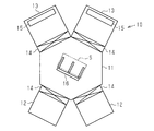
- the sputtering apparatus 10 includes one transfer chamber 11, two load lock chambers 12 connected to the transfer chamber 11, and two sputter chambers 13 connected to the transfer chamber 11.
- One gate valve 14 is arranged between each load lock chamber 12 and the transfer chamber 11 and between each sputter chamber 13 and the transfer chamber 11.
- Each gate valve 14 changes the connection path between the transfer chamber 11 and the corresponding chamber between a communication state and a non-communication state.
- the load lock chamber 12 carries the substrate S to be processed in the sputtering apparatus 10 from the outside to the inside of the sputtering apparatus 10 and carries it out from the inside of the sputtering apparatus 10.
- the load lock chamber 12 opens the interior of the load lock chamber 12 to the atmosphere without being in communication with the transfer chamber 11.
- the load lock chamber 12 is connected to the transfer chamber 11 and is reduced to a predetermined pressure together with the transfer chamber 11. Create a space.
- the sputtering apparatus 10 may be configured to include one load lock chamber 12 or may be configured to include three or more load lock chambers 12.
- the sputter chamber 13 includes a cathode 15, and a predetermined film is formed on one surface of the substrate S by the cathode 15. When a film is formed on the substrate S, the sputter chamber 13 forms an internal space whose pressure is reduced to a pressure equal to or lower than the pressure inside the transfer chamber 11.
- Each of the two sputtering chambers 13 of the sputtering apparatus 10 may include a cathode 15 for forming the same film on the substrate S, or a cathode for forming different films on the substrate S. 15 may be provided. Further, the sputtering apparatus 10 may be configured to include one sputtering chamber 13 or may be configured to include three or more sputtering chambers 13.
- the transfer chamber 11 includes a transfer robot 16 that transfers the substrate S.
- the transfer robot 16 transfers the substrate S before film formation from the load lock chamber 12 to the sputter chamber 13 through the transfer chamber 11, and after film formation from the sputter chamber 13 to the load lock chamber 12 through the transfer chamber 11.
- the substrate S is transported.
- the sputtering apparatus 10 is a chamber other than the load lock chamber 12 and the sputtering chamber 13 described above, for example, a pretreatment chamber for performing processing before forming a film on the substrate S, or after forming a film on the substrate S.
- a post-processing chamber or the like for performing the above processing may be provided.
- the sputtering chamber 13 includes a vacuum chamber 13a, and a substrate holding mechanism 20 for holding the substrate S and a cathode 15 for forming a film on the substrate S are arranged inside the vacuum chamber 13a. Has been.
- the vacuum chamber 13a has a box shape, and has an internal space having a size capable of accommodating the substrate holding mechanism 20 and the cathode 15.
- the internal space of the vacuum chamber 13a is evacuated by an exhaust unit connected to the vacuum chamber 13a, so that the pressure is reduced to a predetermined pressure, for example, a vacuum.
- the cathode 15 is fixed to the inner peripheral surface of the vacuum chamber 13a.
- the cathode 15 is an example of a film forming unit, and includes a backing plate 31 fixed to the inner peripheral surface of the vacuum chamber 13 a and a target 32 fixed to the backing plate 31.
- the substrate holding mechanism 20 includes a stage 21 on which the substrate S is placed, and a changing unit 22 that changes the position of the stage 21 with respect to the cathode 15.
- the stage 21 and the changing unit 22 constitute an example of a holding unit.
- the stage 21 has a placement surface 21S on which the outer peripheral portion of the substrate S is placed.
- the substrate holding mechanism 20 holds the substrate S placed on the placement surface 21S.
- the changing unit 22 changes the position of the stage 21 with respect to the cathode 15 between a position where the stage 21 is substantially orthogonal to the cathode 15 and a position where the stage 21 is substantially parallel to the cathode 15. That is, the changing unit 22 changes the position of the stage 21 between a state where the placement surface 21S is positioned substantially along the horizontal direction and a state where the placement surface 21S is positioned substantially along the vertical direction.
- the placement surface 21 ⁇ / b> S When the stage 21 is in a position substantially parallel to the cathode 15, the placement surface 21 ⁇ / b> S is located at the first position P ⁇ b> 1 facing the cathode 15. On the other hand, when the stage 21 is at a position substantially orthogonal to the cathode 15, the placement surface 21 ⁇ / b> S is located at a second position P ⁇ b> 2 that is different from the first position P ⁇ b> 1 and does not face the cathode 15.
- the changing unit 22 changes the position of the mounting surface 21S between the first position P1 and the second position P2 by changing the position of the stage 21 with respect to the cathode 15, and the position of the mounting surface 21S is changed.
- the posture of the substrate S placed on the placement surface 21S changes.
- the placement surface 21S is at the first position P1
- the entire substrate S held by the substrate holding mechanism 20 is covered with the target 32 in the direction in which the substrate S and the target 32 face each other. That is, the area of the substrate S is smaller than the area of the target 32.
- the changing unit 22 positions the placement surface 21S at the first position P1 where the placement surface 21S of the stage 21 and the cathode 15 face each other. Then, a predetermined sputtering gas is supplied into the vacuum chamber 13 a, and then a voltage is applied to the target 32 from the power source connected to the backing plate 31 through the backing plate 31.
- FIG. 3 for convenience of illustration, only the planar structure of the stage 21 of the substrate holding mechanism 20 is shown, and the outer peripheral portion of the substrate S held by the substrate holding mechanism 20 is indicated by a two-dot chain line.
- the upper side in the direction orthogonal to the paper surface is the upper side in the vertical direction.
- the stage 21 has a rectangular plate shape when viewed from the direction facing the mounting surface 21 ⁇ / b> S, and the substrate S placed on the mounting surface 21 ⁇ / b> S has a rectangular plate shape smaller than the stage 21.
- each of the stage 21 and the substrate S may have a shape different from the rectangular shape, for example, a circular shape or a polygonal shape when viewed from the direction facing the placement surface 21S.
- the stage 21 includes a facing surface 21a that faces the cathode 15 when the mounting surface 21S is located at the first position P1.
- the placement surface 21S is defined as a portion of the facing surface 21a on which the outer peripheral portion Sa of the substrate S is placed.
- the outer peripheral portion Sa of the substrate S is a band-shaped portion having a predetermined width including the outer peripheral edge of the substrate S. That is, the outer peripheral portion Sa of the substrate S has a rectangular ring shape surrounding the central portion of the substrate S.
- the stage 21 has a rectangular plate shape, and the opposing surface 21a of the stage 21 is a substantially flat surface. Therefore, almost the entire inner portion of the facing surface 21a surrounded by the mounting surface 21S is in contact with a part of the non-film-forming surface of the substrate S. In other words, the mounting surface 21S and the inner portion surrounded by the mounting surface 21S out of the facing surface 21a of the stage 21 are in contact with the substrate S.
- the substrate holding mechanism 20 further includes an adsorbing portion 23 that electrostatically adsorbs the substrate S to at least a part of the placement surface 21S.
- the placement surface 21S includes first to fourth side portions 21Sa to 21Sd corresponding to the four sides of the outer peripheral portion Sa of the substrate S. In a state where the stage 21 is positioned substantially along the vertical direction, the first side portion 21Sa of the placement surface 21S is in contact with substantially the entire upper end of the substrate S in the vertical direction, and the second side portion 21Sb is approximately the lower end of the substrate S.
- the third side portion 21Sc is in contact with substantially the entire right end of the substrate S in the vertical direction, and the fourth side portion 21Sb is in contact with substantially the entire left end of the substrate S.
- the adsorption part 23 includes a first part 23a provided on the first side part 21Sa of the placement surface 21S and a second part 23b provided on the second side part 21Sb.
- the first portion 23a and the second portion 23b of the suction portion 23 are respectively connected to the first side portion 21Sa and the second side portion 21Sb of the placement surface 21S corresponding to the upper end and the lower end of the substrate S in the example of FIG.
- the arrangement of the suction portion 23 is not limited to this.
- the suction portion 23 instead of the first and second portions 23a and 23b, the suction portion 23 includes a third portion provided on the third side portion 21Sc of the placement surface 21S corresponding to the right end of the substrate S, and the left end of the substrate S.
- the adsorbing portion 23 includes the third and fourth portions together with the first and second portions 23a and 23b, and adsorbs the first to fourth side portions 21Sa to 21Sd corresponding to the upper, lower, left and right ends of the substrate S, respectively. May be arranged.
- the substrate S When the mounting surface 21S of the stage 21 is positioned at the first position P1, the substrate S is in a state of being positioned substantially along the vertical direction. Therefore, due to the weight of the substrate S, the upper end of the substrate S moves downward in the vertical direction, and the lower end of the substrate S also tries to move downward in the vertical direction.
- the suction portion 23 includes the first side portion 21Sa of the placement surface 21S corresponding to substantially the entire upper end of the substrate S in the vertical direction, and the first of the placement surface 21S corresponding to substantially the entire lower end of the substrate S.
- the configuration located at the two side portions 21Sb is a preferable configuration for suppressing the movement of the substrate S as described above.
- the adsorption part 23 constitutes a part of the facing surface 21a, that is, a part of the placement surface 21S. Therefore, when the outer peripheral portion Sa of the substrate S is placed on the placement surface 21S, the outer peripheral portion Sa of the substrate S and the suction portion 23 are in direct surface contact.
- the substrate S with respect to the mounting surface 21S is changed as the posture of the substrate S is changed as compared with the holding of the substrate S only by the clamp piece where the force for maintaining the position of the substrate S is concentrated on the edge of the substrate S or the like. It is possible to prevent the position of S from changing. Furthermore, since the electrostatic force of the adsorption part 23 acts directly on the substrate S, the substrate S is easily adsorbed by the adsorption part 23.
- the entire surface of the adsorption unit 23 does not have to be in direct contact with the substrate S.
- a part of the surface of the adsorption unit 23 is covered with an adhesion-preventing plate for preventing deposition of film forming species. It may be.
- the suction part 23 Even if the suction part 23 has a configuration in which the entire surface of the suction part 23 is not in direct contact with the substrate S, the suction part 23 only needs to be configured to generate an electrostatic force sufficient to suck the substrate S placed on the placement surface 21S. .
- the suction unit 23 is, for example, an electrostatic chuck that sucks the substrate S by electrostatic force.
- the adsorption unit 23 may be a monopolar electrostatic chuck or a bipolar electrostatic chuck.
- the attracting unit 23 may be an electrostatic chuck that attracts the substrate S by a Coulomb force, an electrostatic chuck that attracts the substrate S by a Johnson-Rahbek force, or a substrate S by a gradient force. It may be an electrostatic chuck that adsorbs.
- the changing unit 22 receives the substrate S before film formation from the transport robot 16, the changing unit 22 moves the stage 21 to a state substantially orthogonal to the cathode 15 to position the mounting surface 21 ⁇ / b> S at the second position P ⁇ b> 2.
- the first and second portions 23 a and 23 b of the suction unit 23 that is, all the suction units 23
- the change unit 22 moves the stage 21.
- the mounting surface 21S is moved to a state substantially parallel to the cathode 15 so as to be positioned at the first position P1.
- the change unit 22 keeps the stage 21 substantially parallel to the cathode 15 from the start to the end of film formation on the substrate S.
- the changing unit 22 moves the stage 21 to a state substantially orthogonal to the cathode 15 to position the placement surface 21S again at the second position P2. Then, the first and second portions 23a and 23b of the suction unit 23 release the suction of the substrate S.
- the formed substrate S is transferred to the transfer robot 16. All the adsorbing portions 23 adsorb the outer peripheral portion Sa of the substrate S until they are unloaded from the substrate holding mechanism 20 to the transfer chamber 11.
- the temperature at the central portion of the facing surface 21a that overlaps the central portion of the substrate S increases.
- the temperature of the opposing surface 21a may become higher than the heat-resistant temperature of the structural member of the adsorption
- the constituent member of the attracting portion 23 forms an electrostatic chuck surface, and an insulating layer in which an electrode is embedded, And a base portion for supporting the insulating layer.
- a resin such as polyimide is used as a material for forming the insulating layer, and aluminum is used as a material for forming the base portion.
- the heat-resistant temperature of these forming materials is, for example, about 200 ° C., and the heat-resistant temperature is a temperature at which the shape of the constituent members can be maintained and the mechanical function can be maintained.
- the adsorption part 23 receives heat during the film forming process and the temperature of the adsorption part 23 becomes higher than the heat resistance temperature of the constituent members, the insulating layer is peeled off from the base part or the base part is deformed.
- the function of the suction unit 23 to stably hold the substrate S is reduced, that is, the function of the suction unit 23 is reduced.
- the suction portion 23 is located on the placement surface 21S in contact with the outer peripheral portion Sa of the substrate S, compared to the configuration in which the suction portion 23 is located at the other part of the facing surface 21a, It is suppressed that the temperature of the adsorption part 23 increases. That is, the temperature of the portion of the facing surface 21a where the suction portion 23 is located is unlikely to be higher than the heat resistance temperature of the constituent members of the suction portion 23, so the temperature of the suction portion 23 is higher than the heat resistance temperature of the constituent members of the suction portion 23. It becomes possible to suppress that the function of the adsorption
- the following effects can be obtained. (1) Since the outer peripheral portion Sa of the substrate S is placed on the placement surface 21S, and the substrate S is attracted to at least a part of the placement surface 21S, a force for maintaining the position of the substrate S is applied to the edge of the substrate S. Concentration on the surface is suppressed by surface contact between the substrate S and the mounting surface 21S. Therefore, the substrate S with respect to the mounting surface 21S is changed as the posture of the substrate S is changed as compared with the holding of the substrate S only by the clamp piece where the force for maintaining the position of the substrate S is concentrated on the edge of the substrate S or the like. It is possible to prevent the position of S from changing.
- the first embodiment described above can be implemented with appropriate modifications as follows.
- maintenance mechanism 20 may be provided with the temperature control part which adjusts the temperature of the board
- the temperature control unit may include a surface located on the same plane as the mounting surface 21S, so that the temperature control unit may be in direct contact with the substrate S, or the entire temperature control unit is inside the stage 21.
- the temperature control part may be in contact with the substrate S indirectly through the stage 21. With reference to FIG. 4 and FIG. 5, an example of a configuration in which the temperature adjustment unit is in direct contact with the substrate S will be described.
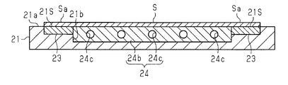
- the metal stage 21 has a groove portion 21c recessed from the facing surface 21a on the inner side of the mounting surface 21S.
- the groove portion 21c is made of metal that closes the water channel 21c1 and the opening of the water channel 21c1. It is comprised from the groove
- a heat medium that is a heating medium or a refrigerant is supplied to the water channel 21c1.
- the depth of the lid groove 21c2 along the vertical direction is substantially equal to the thickness of the lid member 24a, and the lid member 24a is positioned on the same plane as the placement surface 21S by being fitted into the lid groove 21c2.
- the portion of the stage 21 in which the water channel 21c1 is partitioned functions as a temperature adjustment portion 21d that is heated or cooled by the heat medium. Therefore, in the substrate holding mechanism 20 including such a stage 21, the temperature adjustment portion 21 d and the lid member 24 a constitute a temperature adjustment unit 24 that is integral with the stage 21.
- FIG. 5 shows a configuration example of another temperature control unit 24.
- the placement surface 21S of the substrate holding mechanism 20 has an annular shape when viewed from the direction facing the placement surface 21S.
- one recess 21 b that is recessed from the facing surface 21 a is formed in a portion of the facing surface 21 a that is located on the inner side of the placement surface 21 ⁇ / b> S.
- the temperature control part 24 is located inside the recess 21b and has substantially the same size as the space defined by the recess 21b. Therefore, the upper surface of the temperature control part 24 is located on the same plane as the placement surface 21S.
- the temperature control unit 24 includes a metal base 24b that is a separate body from the stage 21, and the base 24b has a water channel 24c to which a heat medium is supplied.
- the size of the base 24b in plan view may be smaller than the space defined by the recess 21b. That is, the temperature control unit 24 may be in a size having a gap between the temperature control unit 24 and the inner wall surface of the stage 21 that partitions the depression 21b while contacting the substrate S.
- the temperature control unit 24 that is a separate body from the stage 21 may be configured to include a base and a lid member.
- the base has a water channel that opens to one surface of the base. The lid member closes the opening of the water channel.
- the temperature control unit 24 is configured to be located inside the mounting surface 21S and in contact with the substrate S, the following effects are provided. Can be obtained. (3) Since the temperature of the substrate S is adjusted by the temperature adjustment unit 24 in contact with the substrate S, the temperature adjustment efficiency of the substrate S is increased.
- the adsorption unit 23 is configured such that when the placement surface 21S is located at the first position P1, the substrate S is placed at a plurality of adsorption sites arranged at intervals on the first side portion 21Sa of the placement surface 21S in contact with the upper end of the substrate S.
- sucks may be sufficient.
- the adsorbing unit 23 is configured such that when the mounting surface 21S is located at the first position P1, the substrate is placed at a plurality of adsorbing sites arranged at intervals on the second side portion 21Sb of the mounting surface 21S that is in contact with the lower end of the substrate S.
- sucks S may be sufficient.
- the suction unit 23 is configured to suck the substrate S at a plurality of suction sites discretely located on the first side 21Sa of the placement surface 21S, and discretely on the second side 21Sb of the placement surface 21S. It may be implemented in combination with a configuration in which the substrate S is adsorbed at a plurality of adsorbing sites located at the same position.
- suction part 23 is, for example, several static electricity along each of the 1st side part 21Sa and 2nd side part 21Sb of the mounting surface 21S. It can be embodied as a configuration in which the electric chucks are arranged at intervals.
- the adsorbing unit 23 is configured such that when the placement surface 21S is located at the first position P1, the first side portion 21Sa of the placement surface 21S in contact with the upper end of the substrate S and the first of the placement surface 21S in contact with the lower end of the substrate S.
- the third side portion 21Sc of the placement surface 21S in contact with the right end of the substrate S and the fourth side of the placement surface 21S in contact with the left end of the substrate S The substrate S may be electrostatically attracted by the portion 21Sd.
- the attracting portion 23 may be configured such that one or more electrostatic chucks are positioned on each of the first to fourth side portions 21Sa to 21Sd of the placement surface 21S.
- suction part 23 may be comprised by one electrostatic chuck which can adsorb
- the cathode 15 may not be fixed to the vacuum chamber 13a, and the cathode 15 is a cathode transport mechanism that changes the position of the cathode 15 relative to the substrate S when the placement surface 21S is located at the first position P1.
- the structure provided may be sufficient.
- the width along the transport direction of the cathode 15, that is, one direction of the four sides of the substrate S is smaller than that of the substrate S. preferable.
- suction part 23 may be the structure in which the 1st part 23a and the 2nd part 23b can adsorb
- the first portion 23a of the suction unit 23 maintains the suction of the substrate S in a state where the changing unit 22 positions the placement surface 21S at the first position P1 or the second position P2.
- the second portion 23b may once cancel the adsorption of the substrate S.
- the suction portion 23 may be sucked in a state of protruding from the placement surface 21S (that is, a state where the substrate S is deformed). Further, film stress is generated by the formation of a film on the substrate S, and the substrate S placed on the placement surface 21S may be deformed. Thus, the substrate S may be deformed before and after the film is formed on the substrate S. Even in such a case, the change of the substrate S can be performed by once releasing the adsorption of the substrate S by the second portion 23b in a state where the changing unit 22 positions the placement surface 21S at the first position P1 or the second position P2.
- the substrate S placed on the placement surface 21S can be held without bending.
- the first portion 23a of the suction portion 23 maintains the suction of the substrate S while the changing portion 22 positions the placement surface 21S at the first position P1 or the second position P2, while the second portion 23b.
- the substrate S may be adsorbed again.
- the adsorption of the substrate S by the second portion 23b of the adsorption unit 23 is once released, and the substrate S is adsorbed again. It becomes possible to adsorb the substrate S without bending after eliminating the deformation of the substrate S placed on the surface 21S.
- the first portion 23a of the suction portion 23 may maintain the suction of the substrate S, while the second portion 23b may release the suction of the substrate S. Then, after the formation of the film on the substrate S is completed, the second portion 23b may adsorb the substrate S again in a state where the changing unit 22 positions the mounting surface 21S at the first position P1. . Thereby, even if the substrate S is deformed by heat input to the substrate S, the adsorption of the substrate S by the second portion 23b is released, so the substrate S is deformed along the mounting surface 21S (heat stretched). ), A flat state can be maintained with respect to the mounting surface 21S.
- the substrate S placed on the placement surface 21S can be adsorbed without bending while the substrate S is flat.
- Such a configuration is effective even when the temperature of the substrate S is adjusted by the temperature adjustment unit 24 and the substrate S is thermally deformed in a state where the mounting surface 21S is located at the second position P2.
- the first portion 23a of the adsorption unit 23 maintains the adsorption of the substrate S, while the second portion 23b releases the adsorption of the substrate S. Therefore, the substrate S is deformed (thermally stretched) along the placement surface 21S, and a flat state with respect to the placement surface 21S can be maintained.
- the deformation of the substrate S is eliminated while the second portion 23b releases the adsorption of the substrate S by utilizing the thermal elongation of the substrate S generated during temperature adjustment. Then, after the deformation of the substrate S is eliminated, the substrate S is adsorbed by the second portion 23b.
- the substrate S may be sucked only from the first portion 23a of the suction portion 23 from the beginning. That is, it is not necessary to suck the substrate S by the whole suction part 23 from the beginning.
- suction is started only with a part of the suction portions 23 (for example, the first portion 23a in FIG. 3), and then in order.
- the remaining suction unit 23 also starts to suck the substrate S, so that the substrate S can be held flat while the deformation of the substrate S is eliminated.
- Such a configuration is also effective when releasing the adsorption of the substrate S after film formation.
- the substrate S after film formation may be deformed while being placed on the placement surface 21S at the second position P2.
- the deformation of the substrate S is canceled at the same time as the release of the suction, so that the positional deviation such as the substrate S slips with respect to the mounting surface 21S. May occur.
- the sputtering apparatus may be configured to transfer the substrate S in a state where the substrate S is set up substantially in the vertical direction.
- FIG. 6 shows a schematic configuration of the sputtering apparatus as viewed from the direction facing the upper end of the substrate S.
- the substrate holding mechanism 40 may include a tray 41 that holds the substrate S, a transport unit 42 that transports the tray 41 along the transport direction D, and a suction unit 23.
- a placement surface 41S on which the outer peripheral portion Sa of the substrate S is placed is formed on one surface of the tray 41, and the suction portion 23 electrostatically attracts the substrate S to at least a part of the placement surface 41S. .
- the transport unit 42 holds the tray 41 with the tray 41 substantially along the vertical direction.
- the transport unit 42 moves the tray 41 along the transport direction D from a position where the tray 41 and the cathode 15 fixed in the vacuum chamber 13 a of the sputtering chamber 13 do not face to a position where the tray 41 and the cathode 15 face each other.
- Transport Further, the transport unit 42 transports the tray 41 along the transport direction D from a position where the tray 41 and the cathode 15 face each other to a position where the tray 41 and the cathode 15 do not face each other.
- the placement surface 41S is positioned at the first position P1 facing the cathode 15.
- the placement surface 41S is located at a second position P2 different from the first position P1.
- the transport unit 42 may fix the position of the substrate S with respect to the cathode 15 when a film is formed on the substrate S held on the tray 41, and the position of the substrate S with respect to the cathode 15 may be set in the transport direction D. You may change along.
- the substrate holding mechanism 50 may include a tray 51 that holds the substrate S, a reversing unit 52 that reverses the tray 51, and a suction unit 23.
- a placement surface 51S on which the outer peripheral portion Sa of the substrate S is placed is formed on one surface of the tray 51, and the suction portion 23 electrostatically attracts the substrate S to at least a part of the placement surface 51S. .
- the reversing unit 52 reverses the tray 51 around the rotation axis along the horizontal direction, so that the substrate S is positioned above the tray 51 and the substrate S is positioned below the tray 51.
- the placement surface 51S is located at a first position facing the film forming unit (cathode 15).
- the placement surface 51S is located at a second position that is different from the first position and does not face the film forming unit (cathode 15).
- the placement surface 51 ⁇ / b> S of the substrate holding mechanism 50 is located at a first position facing the film forming unit (cathode 15) in a state where the substrate S is located below the tray 51, while the substrate S is located on the tray 51.
- the structure located in the 2nd position which does not oppose the film-forming part (cathode 15) in the state located upward may be sufficient.
- the film forming apparatus is not limited to the above-described sputtering apparatus, and may be any apparatus that can form a predetermined film on one surface of the substrate S, such as a vacuum evaporation apparatus.
- the substrate holding mechanism is not limited to that provided in the film forming apparatus such as the sputtering apparatus described above, and may be embodied as a substrate holding mechanism provided in another substrate processing apparatus, for example, an etching apparatus or a laser irradiation apparatus. . -The structure of 1st Embodiment and the modification of 1st Embodiment can also be implemented combining suitably.
- FIG. 8 a substrate holding mechanism, a film forming apparatus, and a substrate holding method according to the second embodiment will be described.
- a sputtering apparatus as an example of a film forming apparatus and a substrate holding mechanism provided in the sputtering apparatus will be described.
- the second embodiment differs from the first embodiment described above in the configuration around the mounting surface in the substrate holding mechanism. Therefore, in the following, such differences will be described in detail, while in the second embodiment, the same reference numerals as those in the first embodiment are assigned to the same components as those in the first embodiment, and detailed description thereof will be omitted.
- the configuration of the substrate holding mechanism 20 will be described with reference to FIG. In FIG. 8, the illustration of the changing unit 22 of the substrate holding mechanism 20 is omitted for convenience of illustration.
- the mounting surface 21S of the substrate holding mechanism 20 has an annular shape when viewed from the direction facing the mounting surface 21S, and the inside of the mounting surface 21S is hollow. That is, in the stage 21 of the substrate holding mechanism 20, one recess 21 b that is recessed from the facing surface 21 a is formed in the portion of the facing surface 21 a inside the placement surface 21 ⁇ / b> S. Therefore, the non-film-forming surface opposite to the film-forming surface of the substrate S facing the cathode 15 is in contact with the mounting surface 21S of the stage 21, but is not in contact with the stage 21 at a portion other than the mounting surface 21S. .
- the substrate S does not contact the stage 21 of the substrate holding mechanism 20 at a portion other than the placement surface 21S, particles including the sputtered particles Sp and the like are present in the contact region between the substrate S and the stage 21. It is suppressed that it is pinched by. Therefore, the non-deposition surface of the substrate S is suppressed from being contaminated or damaged by particles.
- the substrate holding mechanism 20 further includes a temperature adjustment unit 24 that adjusts the temperature of the substrate S, and the temperature adjustment unit 24 is configured to be located inside the placement surface 21S and away from the substrate S. That is, the temperature control unit 24 is located inside the placement surface 21S and inside the recess 21b. In the state where the stage 21 is positioned substantially along the horizontal direction, the depth of the recess 21b along the vertical direction is larger than the width of the temperature adjustment unit 24 along the vertical direction. It is not in contact with the non-deposition surface. For this reason, since the temperature of the substrate S is adjusted by the radiant heat of the temperature adjustment unit 24 located away from the substrate S, variations in temperature distribution in the surface of the substrate S can be suppressed.
- the following effects can be obtained. (4) Since the particles are prevented from being sandwiched between the substrate S and the stage 21, it is possible to suppress the non-deposition surface of the substrate S from being contaminated or damaged by the particles. (5) Since the temperature of the substrate S is adjusted by the radiant heat of the temperature control unit 24 located away from the substrate S, variations in temperature distribution in the surface of the substrate S can be suppressed.
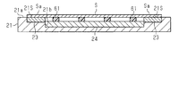
- the temperature control unit 24 includes a first surface (the lower surface in FIG. 9) that contacts the stage 21 and a second surface (the upper surface in FIG. 9) that is located on the opposite side and faces the substrate S. ).
- a plurality of pads 61 may be positioned on the second surface of the temperature control unit 24.
- each pad 61 is an example of a first support portion.
- the plurality of pads 61 are made of resin, and heat conduction through the pads 61 hardly occurs between the temperature adjustment unit 24 and the substrate S. Therefore, the temperature adjustment unit 24 adjusts the temperature of the substrate S by the radiant heat of the temperature adjustment unit 24.
- the thickness of the pad 61 is substantially equal to the distance from the second surface of the temperature control unit 24 to the opposing surface 21a of the stage 21, and the pad 61 is an end surface (tip portion) located on the same plane as the placement surface 21S. have. Therefore, when the substrate S is placed on the placement surface 21 ⁇ / b> S, the end surface of each pad 61 is in contact with the substrate S.
- the pad 61 supports the inner portion of the substrate S that faces the recess 21b, thereby suppressing the inner portion of the substrate S from being bent toward the temperature control unit 24.
- the temperature adjustment unit 24 may be omitted. Even with such a configuration, as long as the recess 21b is formed in the stage 21, it is possible to obtain the effect according to the above-described (4). -Each structure of 2nd Embodiment and the modification of 2nd Embodiment can also be implemented in combination with each structure of the modification of 1st Embodiment suitably.
- a substrate holding mechanism, a film forming apparatus, and a substrate holding method according to the third embodiment will be described with reference to FIGS.
- a sputtering apparatus as an example of a film forming apparatus and a substrate holding mechanism provided in the sputtering apparatus will be described.
- the third embodiment differs from the second embodiment described above in that the substrate holding mechanism includes a support portion that supports the substrate. Therefore, in the following, such differences will be described in detail, while the same components as those in the second embodiment are denoted by the same reference numerals, and detailed description thereof is omitted.
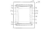
- FIG. 10 for convenience of illustration, only the planar structure of the stage 21 of the substrate holding mechanism 20 is shown as in FIG. 3, and the outer peripheral portion Sa of the substrate S held by the substrate holding mechanism 20 is indicated by a two-dot chain line. It is shown.
- the upper side in the direction orthogonal to the paper surface is the upper side in the vertical direction.
- the illustration of the changing unit 22 of the substrate holding mechanism 20 is omitted as in FIG. 6.
- FIG. 12 for convenience of explanation, a part of the substrate S and a part of the support part are schematically shown.
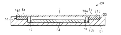
- the substrate holding mechanism 20 further includes a support portion 70 that is an example of a first support portion, and the support portion 70 is disposed inside the placement surface 21 ⁇ / b> S and supports the substrate S.
- the substrate holding mechanism 20 includes a plurality of support portions 70, for example, four support portions 70, and each support portion 70 is located inside the recess 21b.
- the support portion 70 supports the substrate S by having its tip portion in contact with the non-film-forming surface of the substrate S.
- the support unit 70 supports the inner part of the substrate S located inside the placement surface 21S, thereby suppressing the inner part of the substrate S from being bent. That is, the support portion 70 prevents the inner portion of the substrate S facing the recess 21b from being bent toward the bottom of the recess 21b.
- the hollow 21b is a rectangular hole with a bottom, and each support portion 70 is arranged at each of the four corners of the rectangular hole.
- the four support parts 70 surround the temperature control part 24 located inside the recess 21b. That is, the four support portions 70 are disposed outside the temperature adjustment portion 24 in a space surrounded by the depression 21b in a plan view facing the facing surface 21a of the stage 21.
- each support part 70 may be arrange
- each support part 70 may be arrange
- the recess 21b may be a hole other than the rectangular hole, for example, a circular hole.
- each support part 70 should just be arrange
- the substrate holding mechanism 20 may include three or less support portions 70, or may include five or more support portions 70.
- each support portion 70 has a column shape extending along one direction, and when the placement surface 21 ⁇ / b> S of the stage 21 is substantially along the horizontal direction, each support portion 70 is , Extending substantially along the vertical direction.
- the bottom portion of the recess 21b is a flat surface having a rectangular shape, the base end portion 70b of the support portion 70 is located at the bottom portion of the recess 21b, and the support portion 70 extends from the bottom portion of the recess 21b toward the opening of the recess 21b.
- the support part 70 has substantially the same length as the depth of the recess 21 b, and the tip part 70 a of the support part 70 is in contact with the non-film-forming surface of the substrate S.
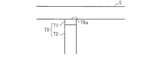
- the distal end portion 70a of the support portion 70 includes a support adsorption portion 71 that electrostatically adsorbs the substrate S.
- the portion of the support portion 70 other than the support suction portion 71 is a support column 72 that supports the support suction portion 71. Since the support unit 70 includes the support adsorption unit 71, a part of the substrate S is adsorbed by the support adsorption unit 71. Therefore, it becomes easier to hold the substrate S placed on the placement surface 21S.
- the support suction part 71 is, for example, an electrostatic chuck, and preferably has a suction function similar to that of the suction part 23 described above.
- the support adsorption part 71 has the front-end
- suction part 71 may be located inside the support pillar 72 of the support part 70, and the support pillar 72 may contact the board
- the following effects can be obtained. (6) Since the support portion 70 is in contact with the inner portion of the substrate S located on the inner side of the placement surface 21S, the inner portion of the substrate S can be prevented from being bent.
- the substrate 21 Since a part of the substrate S is adsorbed by the support adsorption unit 71, the substrate 21 is also placed on the placement surface 21S even when the position of the placement surface 21S changes between the first position P1 and the second position P2.
- the placed substrate S can be suitably held.
- the third embodiment described above can be implemented with appropriate modifications as follows. As long as the substrate holding mechanism 20 includes a plurality of support portions 70, only a part of the support portions 70 among the plurality of support portions 70 may include the support adsorption portions 71.
- the support adsorption part 71 with which the support part 70 is provided may be omitted. Even if it is such a structure, as long as the board
- the temperature adjustment unit 24 may be omitted. Even if it is such a structure, as long as the board
- the configurations of the third embodiment and the modified example of the third embodiment can be implemented in appropriate combination with the configurations of the modified example of the first embodiment and the modified example of the second embodiment.
- a film forming apparatus, a substrate holding mechanism, and a substrate holding method according to a fourth embodiment will be described with reference to FIGS.
- a sputtering apparatus as an example of a film forming apparatus and a substrate holding mechanism provided in the sputtering apparatus will be described.
- the fourth embodiment differs from the first embodiment described above in that the substrate holding mechanism includes a clamp portion. Therefore, in the following, such differences will be described in detail, while the same components as those in the first embodiment are denoted by the same reference numerals, and detailed description thereof will be omitted.
- FIG. 13 shows a configuration in which the clamp portion and the substrate are viewed from the direction facing the end surface of the substrate, and the schematic configuration of the clamp portion and a part of the substrate S is shown in an enlarged manner. .
- the substrate holding mechanism 20 includes a suction unit 23, and the suction unit 23 has a first surface 21 ⁇ / b> S in contact with the upper end of the substrate S in a state where the placement surface 21 ⁇ / b> S is located at the first position P ⁇ b> 1.
- the substrate S is electrostatically attracted to the one side portion 21Sa. That is, the suction surface of the suction portion 23 is exposed at the first side portion 21Sa of the placement surface 21S.
- the entire suction unit 23 may be located inside the stage 21.
- the substrate holding mechanism 20 has a function of positioning the mounting surface 21S at the first position P1 substantially along the vertical direction as described above.
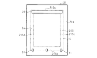
- the substrate holding mechanism 20 further includes a clamp portion 81 that is an example of a second support portion, and the clamp portion 81 is located at the lower end in the vertical direction of the substrate S with the placement surface 21S positioned substantially along the vertical direction.
- the substrate S is pressed toward the placement surface 21S. That is, the clamp unit 81 mechanically supports the substrate S by contacting the edge of the substrate S.
- the substrate holding mechanism 20 includes a plurality of clamp portions 81, for example, three clamp portions 81, and the three clamp portions 81 are arranged at a lower end of the substrate S at a predetermined interval.
- the substrate holding mechanism 20 may be configured to include two or less clamp portions 81, or may be configured to include four or more clamp portions 81.
- the clamp unit 81 includes a holding position where the distance between the clamp unit 81 and the stage 21 is small, the clamp unit 81 and the stage 21 by a position changing unit that changes the position of the clamp unit 81 with respect to the stage 21. It is changed to the non-holding position where the distance between is large.
- the clamp part 81 located at the holding position is indicated by a solid line, while the clamp part 81 located at the non-holding position is indicated by a two-dot chain line.
- the clamp portion 81 When the outer peripheral portion Sa of the substrate S is placed on the placement surface 21S and removed from the placement surface 21S, the clamp portion 81 is located at the non-holding position. On the other hand, when the substrate S is held on the stage 21, the clamp portion 81 is located at the holding position.
- the lower end of the substrate S When the clamp part 81 is located at the holding position, the lower end of the substrate S may be in contact with the clamp part 81, or a gap may be formed between the lower end of the substrate S and the clamp part 81.
- the lower end of the substrate S is supported by the clamp portion 81 when the placement surface 21S is located at the first position P1. Further, even if the substrate S tries to move downward in the vertical direction due to its own weight, the lower end of the substrate S is in contact with the clamp portion 81, which is preferable in that the position of the substrate S is not easily displaced downward.
- stage 21 and the substrate S when the placement surface 21S is located at the second position P2 are indicated by a two-dot chain line, while the placement surface 21S is located at the first position P1.
- stage 21 and the substrate S are indicated by solid lines.
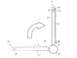
- the change unit 22 changes the position of the placement surface 21 ⁇ / b> S to the second position in a state where the outer peripheral portion Sa of the substrate S is placed on the placement surface 21 ⁇ / b> S. Change from P2 to the first position P1.
- the substrate S is in a state of standing substantially along the vertical direction, so that the weight of the substrate S is applied to the lower end of the substrate S.
- the lower end of the substrate S is pressed against the placement surface 21S by the clamp portion 81 and is mechanically held by the clamp portion 81. And since the lower end surface of the board
- the position of the placement surface 21S is changed from the second position P2 to the second position P2.
- the lower end of the substrate S may move downward in the vertical direction due to its own weight.
- the position of the substrate S with respect to the placement surface 21S can be suppressed from greatly changing. As described above, according to the fourth embodiment, the following effects can be obtained.
- the adsorption unit 23 Before the film is formed on the substrate S, the adsorption unit 23 once removes the adsorption of the substrate S in a state where the changing unit 22 positions the mounting surface 21S at the first position P1, and then adsorbs the substrate S again. May be. Thereby, for example, when the substrate S is adsorbed in a state where a gap is formed between the lower end surface of the substrate S and the clamp portion 81, the adsorption unit 23 once releases the adsorption of the substrate S, whereby the substrate It becomes possible to make the lower end surface of S contact the clamp part 81.
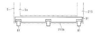
- the suction portion 91 may be configured to electrostatically suck the substrate S at a portion of the mounting surface 21 ⁇ / b> S that is in contact with the lower end of the substrate S except for a portion overlapping the clamp portion 81. . That is, the lower end of the outer peripheral portion Sa of the substrate S may be configured to be held on the placement surface 21S by both the clamp portion 81 and the suction portion 91.
- suction part 91 may be arrange
- FIG. According to such a configuration, when the placement surface 21S is located at the first position P1, in the part of the placement surface 21S, the clamp portion 81 and a portion of the suction portion 91 are aligned along the vertical direction. Yes.
- the position of the lower end of the substrate S with respect to the mounting surface 21S is less likely to change even if the position of the mounting surface 21S changes.
- the clamp part 81 and the suction part 91 may be arranged along the lower end of the substrate S. Even in such a configuration, the position of the lower end of the substrate S relative to the mounting surface 21S is changed as the position of the mounting surface 21S changes compared to a configuration in which the lower end of the substrate S is supported only by the clamp portion 81. It becomes difficult to change. In such a configuration, before the film is formed on the substrate S, after the suction portions 23 and 91 once release the suction of the substrate S in a state where the changing portion 22 positions the placement surface 21S at the first position P1, The substrate S may be adsorbed again.
- the adsorption unit 23 once releases the adsorption of the substrate S, whereby the substrate It becomes possible to make the lower end surface of S contact the clamp part 81. Therefore, the position of the substrate S with respect to the mounting surface 21S can be adjusted to a predetermined position using the clamp unit 81. Alternatively, only the suction unit 91 may temporarily suck the substrate S and then suck the substrate S again.
- the substrate placed on the placement surface 21S is once released by temporarily removing the suction of the substrate S by the suction portion 91. S can be adsorbed without bending.
- the substrate holding mechanism 20 may further include an upper end clamp portion that presses the upper end of the substrate S toward the placement surface 21S, and the side end (right end or left end) of the substrate S faces the placement surface 21S. You may further provide the side edge clamp part (right end clamp part or left end clamp part) to press. Further, in the configuration including the upper end clamp portion, the upper end clamp portion and the suction portion may be arranged along the upper end of the substrate S. Further, the suction portion electrostatically sucks the substrate S over the entire portion (first side portion 21Sa) of the mounting surface 21S that is in contact with the upper end of the substrate S except for the portion overlapping the upper end clamp portion. Also good.
- the side end clamp portion and the suction portion may be arranged along the side end of the substrate S.
- the substrate S is electrostatically applied to the entire portion (second side portion 21Sc or third side portion 21Sd) of the mounting surface 21S that contacts the side end of the substrate S except for the portion where the suction portion overlaps the side end clamp portion.
- sucks automatically may be sufficient.
- the clamp part 81 and an upper end clamp part are examples of a 2nd support part, and in addition to the clamp part 81, a side end clamp part is used. If it is the composition provided, the clamp part 81 and the side end clamp part are examples of the 2nd support part.
- the substrate holding mechanism 20 may be configured to include at least one of the upper end clamp portion and the side end clamp portion while not including the clamp portion 81 in the fourth embodiment described above.
- at least one of the upper end clamp part and the side end clamp part is an example of the second support part.
- the second support unit is not limited to the configuration in which the substrate S is pressed between the mounting surface 21S of the stage 21 by pressing the substrate S against the mounting surface 21S as in the clamp unit 81 described above.
- the configuration may be such that the edge of the substrate S is mechanically supported by contacting the edge of the substrate S without pressing the substrate S against the surface 21S.
- the second support portion can suppress the position of the substrate S from being changed along the facing surface 21 a of the stage 21 by supporting the edge of the substrate S.
- the second support portion includes a portion that prevents the edge of the substrate S from being deformed so as to be separated from the placement surface 21S.
- the edge of the substrate S may be thermally deformed so as to be lifted from the mounting surface 21S due to heat input to the substrate S.
- the second support portion includes a portion that prevents the second support portion from being deformed away from the placement surface 21 ⁇ / b> S, the edge of the substrate can be suppressed from rising.
- the position of the substrate S with respect to the substrate holding mechanism 20 can be prevented from being displaced by both the suction portion 23 and the second support portion as the posture of the substrate S is changed.
Landscapes
- Chemical & Material Sciences (AREA)
- Chemical Kinetics & Catalysis (AREA)
- Engineering & Computer Science (AREA)
- Materials Engineering (AREA)
- Mechanical Engineering (AREA)
- Metallurgy (AREA)
- Organic Chemistry (AREA)
- Physical Vapour Deposition (AREA)
- Container, Conveyance, Adherence, Positioning, Of Wafer (AREA)
- Chemical Vapour Deposition (AREA)
Abstract
Description
この構成によれば、基板保持機構によって保持される基板の温度を温調部によって調節することができる。
上記基板保持機構の他の態様において、前記温調部は、前記載置面の内側に位置して前記基板に接するように構成されていてもよい。
この構成によれば、基板の温度が基板に接する温調部によって調節されるため、基板の温調される効率が高まる。
この構成によれば、第1支持部が、載置面よりも内側に位置する基板の内側部分に接するため、基板の内側部分が撓むことが抑えられる。
この構成によれば、基板の載置面が吸着部によって吸着されることに加えて、基板の縁が第2支持部によって支持されるため、載置面に対する基板の位置が変わることがより抑えられる。
一態様による基板の保持方法は、第1位置と前記第1位置とは異なる第2位置との間で位置を変更可能な載置面上に前記基板の外周部を載置すること、前記載置面の少なくとも一部に前記基板を静電的に吸着することを備える。
好ましくは、前記基板を静電的に吸着することは、前記載置面の少なくとも2箇所で前記基板の外周部を吸着することを含む。
一態様では、前記基板を静電的に吸着することは、前記載置面の少なくとも2箇所のうちの1つで前記基板の外周部の吸着を開始すること、前記少なくとも2箇所の全てで前記吸着が行われる状態となるまで、前記吸着を開始した箇所で前記吸着を維持したまま、前記少なくとも2箇所の各々での前記吸着を順番に開始することを含む。
一態様では、前記基板を静電的に吸着することは、前記載置面の少なくとも2箇所の全てで前記基板の外周部の吸着を開始すること、前記吸着を開始した後、前記少なくとも2箇所のうちの少なくとも1つで前記吸着を解除することを含む。
好ましくは、前記基板を静電的に吸着することは、前記載置面の少なくとも2箇所の全てで前記吸着が行われている状態から前記少なくとも2箇所のうちの少なくとも1つで前記吸着を解除すること、前記吸着を解除した箇所で前記吸着を再開することによって前記少なくとも2箇所の全てで前記吸着を行うことを含む。
一態様では、前記基板は、前記載置面が前記第2位置にあるときに前記載置面上に受け取られ、前記載置面が前記第1位置にあるときに成膜が行われる。この場合、好ましくは、前記基板を静電的に吸着することは、前記載置面が前記第2位置にあるとき、前記載置面の少なくとも2箇所の1つまたは全てで前記吸着を開始すること、前記載置面が前記第2位置または前記第1位置にあるとき、前記載置面の少なくとも2箇所のうちの少なくとも1つで前記吸着を解除することを含む。
また、好ましくは、前記載置面の少なくとも2箇所のうちの少なくとも1つで前記吸着を解除することは、前記基板が成膜される前、前記基板が成膜されている間、および前記基板が成膜された後のうちの少なくとも1つにおいて、前記載置面の前記第1位置で前記吸着を解除することを含む。
一態様では、前記基板保持方法は、前記基板が成膜されて前記載置面が前記第1位置から前記第2位置に戻された後、前記載置面の少なくとも2箇所における前記吸着を順番に解除することを備える。
一態様では、前記載置面の少なくとも2箇所のうちの少なくとも1つで前記吸着を解除することは、前記載置面の少なくとも2箇所のうちの1つで前記吸着を維持しつつ、前記少なくとも2箇所のうちの少なくとも1つの残りの箇所で前記吸着を解除することを含む。
一態様では、前記載置面の少なくとも2箇所のうちの少なくとも1つで前記吸着を解除することは、前記吸着が解除されている間、前記基板の前記外周部をクランプ部によって機械的に保持することを含む。
図1から図3を参照して、第1実施形態の基板保持機構、成膜装置、および基板の保持方法を説明する。第1実施形態では、成膜装置の一例であるスパッタ装置と、そのスパッタ装置に備えられる基板保持機構を説明する。以下では、スパッタ装置の全体構成、スパッタチャンバの構成、基板保持機構の構成、およびスパッタ装置の作用を順番に説明する。
図1を参照してスパッタ装置の全体構成を説明する。
図2を参照してスパッタチャンバ13の構成をさらに説明する。なお、以下では、説明の便宜上から、スパッタチャンバ13の構成のうち、基板Sを保持する基板保持機構20と、基板Sに膜を形成するためのカソード15とについてのみ説明する。
図3を参照して基板保持機構20の構成をより詳しく説明する。なお、図3では、図示の便宜上から、基板保持機構20のステージ21の平面構造のみが示され、基板保持機構20に保持された基板Sの外周部が二点鎖線で示されている。また、図3において、紙面に直交する方向における上方が、鉛直方向における上方である。
なお、吸着部23の第1部分23aと第2部分23bを、図3の例においては基板Sの上端と下端に対応する載置面21Sの第1側部21Saと第2側部21Sbにそれぞれ配したが、吸着部23の配置はこれに限られない。例えば、第1および第2部分23a,23bに代えて、吸着部23は、基板Sの右端に対応する載置面21Sの第3側部21Scに設けられた第3部分と、基板Sの左端に対応する載置面21Sの第4側部21Sdに設けられた第4部分とを含む構成であってもよい。あるいは、吸着部23は、これら第3および第4部分を、第1および第2部分23a,23bと共に含み、基板Sの上下左右端に対応する第1~第4側部21Sa~21Sdにそれぞれ吸着部が配されてもよい。
上述したスパッタ装置10の作用を説明する。
変更部22は、成膜前の基板Sを搬送ロボット16から受け取るとき、ステージ21をカソード15とほぼ直交する状態に移動させることで載置面21Sを第2位置P2に位置させる。そして、基板Sがステージ21に載置されると、吸着部23の第1及び第2部分23a,23b(つまり全ての吸着部23)が基板Sを吸着し、変更部22は、ステージ21をカソード15とほぼ平行な状態に移動させて載置面21Sを第1位置P1に位置させる。また、基板Sへの膜の形成が開始されてから終了するまでの間にわたって、変更部22はステージ21をカソード15とほぼ平行な状態に保つ。
(1)基板Sの外周部Saが載置面21Sに載置され、載置面21Sの少なくとも一部に基板Sが吸着されるため、基板Sの位置を保つための力が基板Sの縁などに集中することが基板Sと載置面21Sとの面接触によって抑えられる。それゆえに、基板Sの位置を保つための力が基板Sの縁などに集中するクランプ片のみによる基板Sの保持と比べて、基板Sの姿勢が変わることに伴って、載置面21Sに対する基板Sの位置が変わることが抑えられる。
・基板保持機構20は、基板Sの温度を調節する温調部を備えていてもよく、温調部は、載置面21Sの内側に位置することが好ましい。なお、温調部が、載置面21Sと同一の平面上に位置する面を含むことで、温調部が基板Sに直に接してもよいし、温調部の全体がステージ21の内部に位置することで、温調部がステージ21を介して基板Sと間接的に接する構成でもよい。
図4および図5を参照して、温調部が基板Sに直に接する構成の例を説明する。なお、図4および図5は、ステージ21がほぼ水平方向に沿って位置する状態でのステージ21の断面構造を示し、ステージ21の対向面21aは、ほぼ水平方向に沿う面である。
図4が示すように、金属製のステージ21は、対向面21aから窪んだ溝部21cを載置面21Sの内側に有し、溝部21cは、水路21c1と、水路21c1の開口を塞ぐ金属製の蓋部材24aが嵌め込まれる蓋用溝21c2とから構成されている。水路21c1には、温媒もしくは冷媒である熱媒体が供給される。鉛直方向に沿う蓋用溝21c2の深さと、蓋部材24aの厚さとはほぼ等しく、蓋部材24aは、蓋用溝21c2に嵌め込まれることによって、載置面21Sと同一の平面上に位置する。
水路21c1が区画されたステージ21の部分は、熱媒体によって加熱もしくは冷却される温調部分21dとして機能する。そのため、こうしたステージ21を備える基板保持機構20では、温調部分21dおよび蓋部材24aが、ステージ21と一体の温調部24を構成している。
図5は別の温調部24の構成例を示す。基板保持機構20の載置面21Sは、載置面21Sと対向する方向から見て、環形状を有している。ステージ21において、載置面21Sよりも内側に位置する対向面21aの部分には、対向面21aから窪んだ1つの窪み21bが形成されている。温調部24は窪み21bの内部に位置し、窪み21bによって区画される空間とほぼ同じ大きさを有している。そのため、温調部24の上面は、載置面21Sと同一の平面上に位置している。温調部24は、ステージ21とは別体である金属製の基体24bを備え、基体24bは、熱媒が供給される水路24cを有している。
なお、基体24bの厚さが窪み21bの深さとほぼ等しい一方で、基体24bの平面視の大きさは、窪み21bによって区画される空間よりも小さくてもよい。すなわち、温調部24は、基板Sに接する一方で、窪み21bを区画するステージ21の内壁面との間に隙間を有する大きさであってもよい。
また、ステージ21と別体である温調部24は、基体と蓋部材とを備える構成であってもよく、この場合には、基体は、基体の1つの面に開口する水路を有し、蓋部材は、水路の開口を塞いでいる。
このように、ステージ21の載置面21Sが環形状を有し、温調部24が載置面21Sの内側に位置して基板Sに接するように構成されていれば、以下に記載の効果を得ることができる。
(3)基板Sの温度が、基板Sに接する温調部24によって調節されるため、基板Sの温調される効率が高まる。
・吸着部23は、第1部分23aと第2部分23bとが、互いに独立したタイミングで、基板Sを吸着することが可能な構成でもよい。こうした構成では、変更部22が載置面21Sを第1位置P1または第2位置P2に位置させた状態で、例えば、吸着部23の第1部分23aが基板Sの吸着を維持する一方で、第2部分23bは、基板Sの吸着を一旦解除してもよい。
基板Sが載置面21Sに載置される際、すなわち、ステージ21の載置面21Sがカソード15と対向しない第2位置P2に位置し、この位置で基板Sの外周部Saを吸着部23によって吸着する際、一度に全ての吸着部23(図3の例では第1部分23aおよび第2部分23b)で基板Sを吸着しようとすると、吸着のタイミングのずれにより、基板Sの一部が載置面21Sから突き出る状態(つまり基板Sが変形した状態)で吸着部23によって吸着されることがある。
また、基板Sへの膜の形成によって膜応力が発生し、載置面21Sに載置された基板Sが変形する場合もある。
このように、基板Sへの膜の形成前および膜の形成後に基板Sが変形することがある。こうした場合にも、変更部22が載置面21Sを第1位置P1または第2位置P2に位置させた状態で、第2部分23bによる基板Sの吸着を一旦解除することによって基板Sの変形を解消でき、載置面21Sに載置された基板Sを撓み無く保持することが可能になる。
また、変更部22が載置面21Sを第1位置P1または第2位置P2に位置させた状態で、吸着部23の第1部分23aが基板Sの吸着を維持する一方で、第2部分23bが基板Sの吸着を一旦解除した後、再び基板Sを吸着してもよい。
このように、載置面21Sに載置された基板Sが変形した場合に、吸着部23の第2部分23bによる基板Sの吸着を一旦解除し、再び基板Sを吸着することによって、載置面21Sに載置された基板Sの変形を解消したうえで基板Sを撓み無く吸着することが可能になる。
また、基板Sへの膜の形成中に、吸着部23の第1部分23aが基板Sの吸着を維持する一方で、第2部分23bは基板Sの吸着を解除してもよい。そして、基板Sへの膜の形成が終了した後、変更部22が載置面21Sを第1位置P1に位置させている状態で、第2部分23bが、再び基板Sを吸着してもよい。これにより、基板Sへの入熱によって基板Sが変形しても、第2部分23bによる基板Sの吸着を解除しているため、基板Sが載置面21Sに沿って変形し(熱伸びし)、載置面21Sに対して平坦な状態を維持することができる。さらに、載置面21Sに載置された基板Sが平坦な状態で基板Sを撓み無く吸着することが可能になる。
このような構成は、載置面21Sが第2位置P2に位置した状態で、温調部24により基板Sの温度が調節され、基板Sに熱変形が発生する場合でも有効である。温調部24による温度調節により基板Sが熱伸びをする場合でも、吸着部23の第1部分23aが基板Sの吸着を維持する一方で、第2部分23bが基板Sの吸着を解除しているため、基板Sが載置面21Sに沿って変形し(熱伸びし)、載置面21Sに対して平坦な状態を維持することができる。言い換えれば、温度調節の際に生じる基板Sの熱伸びを利用して、第2部分23bが基板Sの吸着を解除している間に基板Sの変形を解消する。そして、基板Sの変形を解消した後に、第2部分23bによる基板Sの吸着を行う。
なお、この場合には、基板Sが載置面21Sに載置される際に、はじめから吸着部23の第1部分23aのみで基板Sを吸着すればよい。つまり、はじめから吸着部23全てで基板Sを吸着する必要はない。このように、第2位置P2で基板Sが載置面21Sに載置される際に、はじめに一部の吸着部23(図3では例えば第1部分23a)のみで吸着を開始し、その後順に残りの吸着部23(図3では第2部分23b)も基板Sの吸着を開始することで、基板Sの変形を解消しながら基板Sを平坦に保持することが可能となる。
このような構成は、成膜後の基板Sの吸着を解除する際にも有効である。たとえば、成膜後の基板Sが第2位置P2において載置面21Sに載置された状態で変形している場合がある。その場合において、複数の吸着部23が一度に吸着を解除すると、吸着の解除と同時に基板Sの変形が一度に解消し、このため、基板Sが載置面21Sに対して滑るなどの位置ずれが発生する恐れがある。
このような場合に、複数の吸着部23を順に解除することによって基板Sの変形を段階的に解消することが可能となり、最後の吸着部23を解除する際には既に基板Sは載置面21Sに対して平坦な状態とすることができているため、基板Sが載置面21Sに対して位置ずれを発生することがない。
・成膜装置は、上述したスパッタ装置に限らず、例えば、真空蒸着装置など、基板Sの1つの面に対して所定の膜を形成することの可能な装置であればよい。
・第1実施形態および第1実施形態の変形例の構成は、適宜組み合わせて実施することもできる。
図8を参照して、第2実施形態の基板保持機構、成膜装置、および基板の保持方法を説明する。第2実施形態では、成膜装置の一例であるスパッタ装置と、そのスパッタ装置に備えられる基板保持機構を説明する。なお、第2実施形態は、上述した第1実施形態と比べて、基板保持機構における載置面の周辺の構成が異なる。そのため、以下では、こうした相違点を詳しく説明する一方で、第2実施形態において第1実施形態と共通する構成には、第1実施形態と同じ符号を付すことによって、その詳しい説明を省略する。
図8を参照して、基板保持機構20の構成を説明する。なお、図8では、図示の便宜上から、基板保持機構20の変更部22の図示が省略されている。
図8が示すように、基板保持機構20の載置面21Sは、載置面21Sと対向する方向から見て環形状を有し、載置面21Sの内側が中空である。すなわち、基板保持機構20のステージ21において、載置面21Sよりも内側における対向面21aの部分には、対向面21aから窪んだ1つの窪み21bが形成されている。そのため、カソード15と対向する基板Sの成膜面とは反対側の非成膜面は、ステージ21の載置面21Sに接する一方で、載置面21S以外の部分でステージ21に接していない。
そのため、基板Sの温度が、基板Sから離れて位置する温調部24の輻射熱によって調節されるため、基板Sの面内における温度分布のばらつきが抑えられる。
(4)パーティクルが基板Sとステージ21とによって挟まれることが抑えられるため、基板Sにおける非成膜面が、パーティクルによって汚染されたり傷付けられたりすることが抑えられる。
(5)基板Sの温度が、基板Sから離れて位置する温調部24の輻射熱によって調節されるため、基板Sの面内における温度分布のばらつきが抑えられる。
・図9が示すように、温調部24は、ステージ21に接する第1面(図9では下面)と、その反対側に位置して、基板Sと対向する第2面(図9では上面)とを含む。この温調部24の第2面に複数のパッド61が位置してもよい。図9の構成では、各パッド61が第1支持部の一例である。複数のパッド61は樹脂製であり、温調部24と基板Sとの間において、パッド61を介した熱の伝導はほぼ生じない。そのため、温調部24は、温調部24の輻射熱によって基板Sの温度を調節する。
パッド61の厚さは、温調部24の第2面からステージ21の対向面21aまでの距離とほぼ等しく、パッド61は、載置面21Sと同一の平面上に位置する端面(先端部)を有している。そのため、載置面21Sに基板Sが載置されたとき、各パッド61の端面は基板Sに接する。
パッド61は、窪み21bと対向する基板Sの内側部分を支持することで、その基板Sの内側部分が温調部24に向けて撓むことを抑える。そのため、基板Sが温調部24に接することが抑えられ、結果として、基板Sの温度が急激に変わることによって、基板Sにストレスが加わることが抑えられる。また、基板Sが温調部24に接することが抑えられるため、基板Sが温調部24によって傷付けられることが抑えられる。
・基板保持機構20において、温調部24が割愛されてもよい。こうした構成によっても、ステージ21に窪み21bが形成されている以上は、上述した(4)に準じた効果を得ることはできる。
・第2実施形態および第2実施形態の変形例の各々の構成は、第1実施形態の変形例の各々の構成と適宜組み合わせて実施することもできる。
図10から図12を参照して、第3実施形態の基板保持機構、成膜装置、および基板の保持方法を説明する。第3実施形態では、成膜装置の一例であるスパッタ装置と、そのスパッタ装置に備えられる基板保持機構を説明する。なお、第3実施形態は、上述した第2実施形態と比べて、基板保持機構が基板を支持する支持部を備える点が異なる。そのため、以下では、こうした相違点を詳しく説明する一方で、第2実施形態と同じ構成には同じ符号を付すことによって、その詳しい説明を省略する。
図10から図12を参照して、基板保持機構20の構成を説明する。なお、図10では、図示の便宜上から、図3と同様、基板保持機構20のステージ21の平面構造のみが示され、基板保持機構20に保持された基板Sの外周部Saが二点鎖線で示されている。また、図10において、紙面に直交する方向の上方が鉛直方向の上方である。そして、図11では、図示の便宜上から、図6と同様、基板保持機構20の変更部22の図示が省略されている。また、図12では、説明の便宜上から、基板Sの一部と、支持部の一部とが概略的に示されている。
(6)支持部70が、載置面21Sよりも内側に位置する基板Sの内側部分に接するため、基板Sの内側部分が撓むことが抑えられる。
・基板保持機構20が複数の支持部70を備える構成であれば、複数の支持部70のうち、一部の支持部70のみが支持吸着部71を備えていてもよい。
図13から図15を参照して、第4実施形態の成膜装置、基板保持機構、および基板の保持方法を説明する。第4実施形態では、成膜装置の一例であるスパッタ装置と、そのスパッタ装置に備えられる基板保持機構を説明する。なお、第4実施形態は、上述した第1実施形態と比べて、基板保持機構がクランプ部を備える点が異なる。そのため、以下では、こうした相違点を詳しく説明する一方で、第1実施形態と同じ構成には同じ符号を付すことによって、その詳しい説明を省略する。
図13から図15を参照して基板保持機構20の構成を説明する。なお、図13では、図示の便宜上から、図3と同様、基板保持機構20のステージ21の平面構造のみが示され、基板保持機構20に保持された基板Sの外周部Saが二点鎖線で示されている。また、図13において、紙面に直交する方向の上方が鉛直方向の上方である。そして、図14には、クランプ部と基板とを基板の端面と対向する方向から見た構成であって、クランプ部と基板Sの一部との概略的な構成が拡大して示されている。
図15を参照して、基板保持機構20の作用を説明する。なお、図15では、図示の便宜上から、載置面21Sが第2位置P2に位置するときのステージ21および基板Sが二点鎖線で示される一方で、載置面21Sが第1位置P1に位置するときのステージ21および基板Sが実線で示されている。
以上説明したように、第4実施形態によれば、以下に記載の効果を得ることができる。
・基板Sへの膜の形成前において、変更部22が載置面21Sを第1位置P1に位置させた状態で、吸着部23が基板Sの吸着を一旦解除した後、再び基板Sを吸着してもよい。これにより、例えば、基板Sの下端面とクランプ部81との間に隙間が形成された状態で基板Sが吸着された場合に、吸着部23が基板Sの吸着を一旦解除することによって、基板Sの下端面をクランプ部81に接触させることが可能になる。そのため、載置面21Sに対する基板Sの位置をクランプ部81を用いて所定の位置に合わせることが可能になる。
・図16が示すように、吸着部91は、クランプ部81と重なる部分以外で基板Sの下端と接する載置面21Sの部分において、基板Sを静電的に吸着する構成であってもよい。すなわち、基板Sの外周部Saのうちの下端が、クランプ部81と吸着部91との両方によって、載置面21Sに保持される構成であってもよい。
こうした構成では、基板Sへの膜の形成前において、変更部22が載置面21Sを第1位置P1に位置させた状態で、吸着部23,91が基板Sの吸着を一旦解除した後、再び基板Sを吸着してもよい。これにより、例えば、基板Sの下端面とクランプ部81との間に隙間が形成された状態で基板Sが吸着された場合に、吸着部23が基板Sの吸着を一旦解除することによって、基板Sの下端面をクランプ部81に接触させることが可能になる。そのため、載置面21Sに対する基板Sの位置をクランプ部81を用いて所定の位置に合わせることが可能になる。
また、吸着部91のみが基板Sの吸着を一旦解除した後、再び基板Sを吸着してもよい。このように、基板Sが載置面21Sから突き出る状態で吸着部23によって吸着される構成において、吸着部91による基板Sの吸着を一旦解除することによって、載置面21Sに載置された基板Sを撓み無く吸着することが可能になる。
Claims (18)
- 基板の外周部が載置される載置面を有して前記載置面上に前記基板を保持する保持部であって、前記載置面の位置を、第1位置と、前記第1位置とは異なる第2位置との間で変える前記保持部を備え、
前記保持部は、
前記載置面の少なくとも一部に前記基板を静電的に吸着する吸着部を備える、
基板保持機構。 - 前記基板の温度を温調する温調部をさらに備え、
前記載置面は環形状を有し、
前記温調部は、前記載置面の内側に位置している、
請求項1に記載の基板保持機構。 - 前記温調部は、前記載置面の内側に位置して前記基板から離れるように構成されている、
請求項2に記載の基板保持機構。 - 前記温調部は、前記載置面の内側に位置して前記基板に接するように構成されている、
請求項2に記載の基板保持機構。 - 前記載置面の内側に配置され、前記基板を支持する第1支持部をさらに備える
請求項3に記載の基板保持機構。 - 前記第1支持部は、前記基板に接する先端部を備え、
前記先端部は、前記基板を静電的に吸着する支持吸着部を備える、
請求項5に記載の基板保持機構。 - 前記保持部は、前記基板の縁を機械的に支持する第2支持部をさらに備える、
請求項1から6のうちのいずれか一項に記載の基板保持機構。 - 基板に向けて成膜種を放出する成膜部と、
前記基板の外周部が載置される載置面を有して前記載置面上に前記基板を保持する保持部であって、前記載置面の位置を、前記成膜部と対向する第1位置と、前記第1位置とは異なる第2位置との間で変える前記保持部とを備え、
前記保持部は、
前記載置面の少なくとも一部に前記基板を静電的に吸着する吸着部を備える、
成膜装置。 - 基板の保持方法であって、
第1位置と前記第1位置とは異なる第2位置との間で位置を変更可能な載置面上に前記基板の外周部を載置すること、
前記載置面の少なくとも一部に前記基板を静電的に吸着すること、
を備える基板の保持方法。 - 前記基板を静電的に吸着することは、前記載置面の少なくとも2箇所で前記基板の外周部を吸着することを含む、
請求項9に記載の基板の保持方法。 - 前記基板を静電的に吸着することは、
前記載置面の少なくとも2箇所のうちの1つで前記基板の外周部の吸着を開始すること、
前記少なくとも2箇所の全てで前記吸着が行われる状態となるまで、前記吸着を開始した箇所で前記吸着を維持したまま、前記少なくとも2箇所の各々での前記吸着を順番に開始することを含む、
請求項10に記載の基板の保持方法。 - 前記基板を静電的に吸着することは、
前記載置面の少なくとも2箇所の全てで前記基板の外周部の吸着を開始すること、
前記吸着を開始した後、前記少なくとも2箇所のうちの少なくとも1つで前記吸着を解除することを含む、
請求項10に記載の基板の保持方法。 - 前記基板を静電的に吸着することは、
前記載置面の少なくとも2箇所の全てで前記吸着が行われている状態から前記少なくとも2箇所のうちの少なくとも1つで前記吸着を解除すること、
前記吸着を解除した箇所で前記吸着を再開することによって前記少なくとも2箇所の全てで前記吸着を行うことを含む、
請求項10から12のうちいずれか一項に記載の基板の保持方法。 - 前記基板は、前記載置面が前記第2位置にあるときに前記載置面上に受け取られ、前記載置面が前記第1位置にあるときに成膜が行われるものであり、
前記基板を静電的に吸着することは、
前記載置面が前記第2位置にあるとき、前記載置面の少なくとも2箇所の1つまたは全てで前記吸着を開始すること、
前記載置面が前記第2位置または前記第1位置にあるとき、前記載置面の少なくとも2箇所のうちの少なくとも1つで前記吸着を解除することを含む、
請求項10から13のうちのいずれか一項に記載の基板の保持方法。 - 前記載置面の少なくとも2箇所のうちの少なくとも1つで前記吸着を解除することは、
前記基板が成膜される前、前記基板が成膜されている間、および前記基板が成膜された後のうちの少なくとも1つにおいて、前記載置面の前記第1位置で前記吸着を解除することを含む、
請求項14に記載の基板の保持方法。 - 前記基板が成膜されて前記載置面が前記第1位置から前記第2位置に戻された後、前記載置面の少なくとも2箇所における前記吸着を順番に解除すること
を備える請求項14または15に記載の基板の保持方法。 - 前記載置面の少なくとも2箇所のうちの少なくとも1つで前記吸着を解除することは、
前記載置面の少なくとも2箇所のうちの1つで前記吸着を維持しつつ、前記少なくとも2箇所のうちの少なくとも1つの残りの箇所で前記吸着を解除することを含む、
請求項12から15のうちのいずれか一項に記載の基板の保持方法。 - 前記載置面の少なくとも2箇所のうちの少なくとも1つで前記吸着を解除することは、
前記吸着が解除されている間、前記基板の前記外周部をクランプ部によって機械的に保持することを含む、
請求項12から15のうちのいずれか一項に記載の基板の保持方法。
Priority Applications (3)
| Application Number | Priority Date | Filing Date | Title |
|---|---|---|---|
| JP2017512536A JP6526795B2 (ja) | 2015-04-15 | 2016-04-12 | 基板の保持方法 |
| CN201680021346.7A CN107429386B (zh) | 2015-04-15 | 2016-04-12 | 基板保持机构、成膜装置、及基板的保持方法 |
| KR1020177032598A KR102083443B1 (ko) | 2015-04-15 | 2016-04-12 | 기판홀딩기구, 성막 장치, 및 기판의 홀딩방법 |
Applications Claiming Priority (2)
| Application Number | Priority Date | Filing Date | Title |
|---|---|---|---|
| JP2015-083331 | 2015-04-15 | ||
| JP2015083331 | 2015-04-15 |
Publications (1)
| Publication Number | Publication Date |
|---|---|
| WO2016167233A1 true WO2016167233A1 (ja) | 2016-10-20 |
Family
ID=57126572
Family Applications (1)
| Application Number | Title | Priority Date | Filing Date |
|---|---|---|---|
| PCT/JP2016/061750 Ceased WO2016167233A1 (ja) | 2015-04-15 | 2016-04-12 | 基板保持機構、成膜装置、および基板の保持方法 |
Country Status (5)
| Country | Link |
|---|---|
| JP (1) | JP6526795B2 (ja) |
| KR (1) | KR102083443B1 (ja) |
| CN (1) | CN107429386B (ja) |
| TW (1) | TWI636150B (ja) |
| WO (1) | WO2016167233A1 (ja) |
Cited By (6)
| Publication number | Priority date | Publication date | Assignee | Title |
|---|---|---|---|---|
| CN108300975A (zh) * | 2017-01-12 | 2018-07-20 | 株式会社爱发科 | 基板保持器、纵式基板输送装置以及基板处理装置 |
| CN108624857A (zh) * | 2017-05-22 | 2018-10-09 | 佳能特机株式会社 | 基板载置方法和机构、成膜方法和装置、电子器件制造方法及有机el显示装置制造方法 |
| KR20190022767A (ko) * | 2017-06-28 | 2019-03-06 | 가부시키가이샤 아루박 | 스퍼터 장치 |
| KR20200080198A (ko) | 2017-11-10 | 2020-07-06 | 가부시키가이샤 알박 | 진공 장치, 흡착 장치, 도전성 박막 제조 방법 |
| JP2021057530A (ja) * | 2019-10-01 | 2021-04-08 | キヤノントッキ株式会社 | 回転駆動装置 |
| JP2022024690A (ja) * | 2020-07-28 | 2022-02-09 | 株式会社アルバック | 吸着装置及び真空処理装置 |
Families Citing this family (4)
| Publication number | Priority date | Publication date | Assignee | Title |
|---|---|---|---|---|
| CN108048818A (zh) * | 2017-12-18 | 2018-05-18 | 德淮半导体有限公司 | 化学气相沉积装置及其使用方法 |
| KR102427823B1 (ko) * | 2018-06-11 | 2022-07-29 | 캐논 톡키 가부시키가이샤 | 정전척 시스템, 성막장치, 흡착방법, 성막방법 및 전자 디바이스의 제조방법 |
| KR102419064B1 (ko) * | 2018-07-31 | 2022-07-07 | 캐논 톡키 가부시키가이샤 | 정전척 시스템, 성막장치, 흡착방법, 성막방법 및 전자 디바이스의 제조방법 |
| KR102430370B1 (ko) * | 2018-07-31 | 2022-08-05 | 캐논 톡키 가부시키가이샤 | 정전척 시스템, 성막장치, 흡착방법, 성막방법 및 전자 디바이스의 제조방법 |
Citations (7)
| Publication number | Priority date | Publication date | Assignee | Title |
|---|---|---|---|---|
| JPH10183345A (ja) * | 1996-12-18 | 1998-07-14 | Nissin Electric Co Ltd | 基板保持装置 |
| JP2001160585A (ja) * | 2000-09-11 | 2001-06-12 | Hitachi Ltd | 基板保持装置 |
| JP2002009064A (ja) * | 2000-06-21 | 2002-01-11 | Hitachi Ltd | 試料の処理装置及び試料の処理方法 |
| JP2003142570A (ja) * | 2001-10-31 | 2003-05-16 | Ulvac Japan Ltd | 真空処理装置及び処理対象物の処理方法 |
| JP2003347393A (ja) * | 2002-05-29 | 2003-12-05 | Ulvac Japan Ltd | 基板保持装置、及びその基板保持装置を用いた真空処理装置 |
| JP2007162063A (ja) * | 2005-12-13 | 2007-06-28 | Dainippon Printing Co Ltd | スパッタ装置および基板搬送用キャリア |
| JP2009249662A (ja) * | 2008-04-03 | 2009-10-29 | Ulvac Japan Ltd | 真空処理装置 |
Family Cites Families (6)
| Publication number | Priority date | Publication date | Assignee | Title |
|---|---|---|---|---|
| JPH07258839A (ja) * | 1994-03-18 | 1995-10-09 | Hitachi Ltd | スパッタリング装置 |
| JP4098283B2 (ja) | 2004-07-30 | 2008-06-11 | 株式会社アルバック | スパッタリング装置 |
| JP2009146932A (ja) * | 2007-12-11 | 2009-07-02 | Ulvac Japan Ltd | 基板搬送装置、基板搬送方法及び真空処理装置 |
| JP2014078602A (ja) * | 2012-10-10 | 2014-05-01 | Sumitomo Heavy Ind Ltd | 基板搬送トレイ起伏装置 |
| JP2014078600A (ja) * | 2012-10-10 | 2014-05-01 | Sumitomo Heavy Ind Ltd | 成膜装置 |
| JP6064684B2 (ja) * | 2013-03-05 | 2017-01-25 | 三星ダイヤモンド工業株式会社 | 基板処理システムおよび基板反転装置 |
-
2016
- 2016-04-12 KR KR1020177032598A patent/KR102083443B1/ko active Active
- 2016-04-12 CN CN201680021346.7A patent/CN107429386B/zh active Active
- 2016-04-12 WO PCT/JP2016/061750 patent/WO2016167233A1/ja not_active Ceased
- 2016-04-12 JP JP2017512536A patent/JP6526795B2/ja active Active
- 2016-04-13 TW TW105111468A patent/TWI636150B/zh active
Patent Citations (7)
| Publication number | Priority date | Publication date | Assignee | Title |
|---|---|---|---|---|
| JPH10183345A (ja) * | 1996-12-18 | 1998-07-14 | Nissin Electric Co Ltd | 基板保持装置 |
| JP2002009064A (ja) * | 2000-06-21 | 2002-01-11 | Hitachi Ltd | 試料の処理装置及び試料の処理方法 |
| JP2001160585A (ja) * | 2000-09-11 | 2001-06-12 | Hitachi Ltd | 基板保持装置 |
| JP2003142570A (ja) * | 2001-10-31 | 2003-05-16 | Ulvac Japan Ltd | 真空処理装置及び処理対象物の処理方法 |
| JP2003347393A (ja) * | 2002-05-29 | 2003-12-05 | Ulvac Japan Ltd | 基板保持装置、及びその基板保持装置を用いた真空処理装置 |
| JP2007162063A (ja) * | 2005-12-13 | 2007-06-28 | Dainippon Printing Co Ltd | スパッタ装置および基板搬送用キャリア |
| JP2009249662A (ja) * | 2008-04-03 | 2009-10-29 | Ulvac Japan Ltd | 真空処理装置 |
Cited By (14)
| Publication number | Priority date | Publication date | Assignee | Title |
|---|---|---|---|---|
| CN108300975A (zh) * | 2017-01-12 | 2018-07-20 | 株式会社爱发科 | 基板保持器、纵式基板输送装置以及基板处理装置 |
| CN108624857A (zh) * | 2017-05-22 | 2018-10-09 | 佳能特机株式会社 | 基板载置方法和机构、成膜方法和装置、电子器件制造方法及有机el显示装置制造方法 |
| CN108624857B (zh) * | 2017-05-22 | 2020-09-25 | 佳能特机株式会社 | 基板载置方法和机构、成膜方法和装置、电子器件制造方法及有机el显示装置制造方法 |
| KR20190022767A (ko) * | 2017-06-28 | 2019-03-06 | 가부시키가이샤 아루박 | 스퍼터 장치 |
| KR102182582B1 (ko) | 2017-06-28 | 2020-11-24 | 가부시키가이샤 아루박 | 스퍼터 장치 |
| US11473188B2 (en) | 2017-06-28 | 2022-10-18 | Ulvac, Inc. | Sputtering apparatus |
| US10982323B2 (en) | 2017-11-10 | 2021-04-20 | Ulv Ac, Inc. | Conductive thin film manufacturing method |
| KR20200080198A (ko) | 2017-11-10 | 2020-07-06 | 가부시키가이샤 알박 | 진공 장치, 흡착 장치, 도전성 박막 제조 방법 |
| JP2021057530A (ja) * | 2019-10-01 | 2021-04-08 | キヤノントッキ株式会社 | 回転駆動装置 |
| KR20210039274A (ko) * | 2019-10-01 | 2021-04-09 | 캐논 톡키 가부시키가이샤 | 회전 구동 장치 |
| JP7288832B2 (ja) | 2019-10-01 | 2023-06-08 | キヤノントッキ株式会社 | 回転駆動装置 |
| KR102911088B1 (ko) * | 2019-10-01 | 2026-01-09 | 캐논 톡키 가부시키가이샤 | 회전 구동 장치 |
| JP2022024690A (ja) * | 2020-07-28 | 2022-02-09 | 株式会社アルバック | 吸着装置及び真空処理装置 |
| JP7449806B2 (ja) | 2020-07-28 | 2024-03-14 | 株式会社アルバック | 吸着装置及び真空処理装置 |
Also Published As
| Publication number | Publication date |
|---|---|
| KR102083443B1 (ko) | 2020-03-02 |
| KR20170134743A (ko) | 2017-12-06 |
| CN107429386B (zh) | 2019-09-27 |
| JPWO2016167233A1 (ja) | 2018-01-11 |
| TWI636150B (zh) | 2018-09-21 |
| TW201708586A (zh) | 2017-03-01 |
| CN107429386A (zh) | 2017-12-01 |
| JP6526795B2 (ja) | 2019-06-05 |
Similar Documents
| Publication | Publication Date | Title |
|---|---|---|
| JP6526795B2 (ja) | 基板の保持方法 | |
| JP4703050B2 (ja) | 基板のデチャック方法及び装置 | |
| JP6215871B2 (ja) | ガス導入開口を備えた基板支持体 | |
| JP5001432B2 (ja) | 基板処理装置及び基板処理方法 | |
| KR102264575B1 (ko) | 기판 보유 지지 기구 및 성막 장치 | |
| JP4774025B2 (ja) | 吸着装置、搬送装置 | |
| TW201513262A (zh) | 原位可移除式靜電吸盤 | |
| CN103824800A (zh) | 基板载置台和基板处理装置 | |
| TWI868187B (zh) | 為了產量效率預對準載體、晶圓及載體-晶圓組合的方法 | |
| CN106165056A (zh) | 基板载体 | |
| JP2011184751A (ja) | 冷却機構 | |
| JP6851202B2 (ja) | 基板ホルダ、縦型基板搬送装置及び基板処理装置 | |
| JP6824003B2 (ja) | 静電チャック付きトレイ | |
| CN107210253A (zh) | 基板移载系统 | |
| JP2009099957A (ja) | 表示用基板の製造方法および真空処理装置 | |
| CN107873062B (zh) | 用于固持基板的方法和支撑件 | |
| CN113571459B (zh) | 用于制造显示装置的设备和用于制造显示装置的方法 | |
| JP4783094B2 (ja) | プラズマ処理用環状部品、プラズマ処理装置、及び外側環状部材 | |
| KR101517720B1 (ko) | 정전척 및 이를 포함하는 플라즈마 발생장치 | |
| JP5953012B2 (ja) | 基板保持装置 | |
| JP5335421B2 (ja) | 真空処理装置 | |
| KR20110051686A (ko) | 기판 트레이 유닛 | |
| JP2004047912A (ja) | 吸着装置及び真空処理装置 | |
| TWI860323B (zh) | 基板載具 | |
| JP2010161169A (ja) | 真空処理装置、真空処理方法 |
Legal Events
| Date | Code | Title | Description |
|---|---|---|---|
| 121 | Ep: the epo has been informed by wipo that ep was designated in this application |
Ref document number: 16780024 Country of ref document: EP Kind code of ref document: A1 |
|
| ENP | Entry into the national phase |
Ref document number: 2017512536 Country of ref document: JP Kind code of ref document: A |
|
| NENP | Non-entry into the national phase |
Ref country code: DE |
|
| ENP | Entry into the national phase |
Ref document number: 20177032598 Country of ref document: KR Kind code of ref document: A |
|
| 122 | Ep: pct application non-entry in european phase |
Ref document number: 16780024 Country of ref document: EP Kind code of ref document: A1 |