WO2016104130A1 - ジョイントコネクタ - Google Patents
ジョイントコネクタ Download PDFInfo
- Publication number
- WO2016104130A1 WO2016104130A1 PCT/JP2015/084321 JP2015084321W WO2016104130A1 WO 2016104130 A1 WO2016104130 A1 WO 2016104130A1 JP 2015084321 W JP2015084321 W JP 2015084321W WO 2016104130 A1 WO2016104130 A1 WO 2016104130A1
- Authority
- WO
- WIPO (PCT)
- Prior art keywords
- terminal
- tab
- joint
- terminals
- female
- Prior art date
- Legal status (The legal status is an assumption and is not a legal conclusion. Google has not performed a legal analysis and makes no representation as to the accuracy of the status listed.)
- Ceased
Links
Images







Classifications
-
- H—ELECTRICITY
- H01—ELECTRIC ELEMENTS
- H01B—CABLES; CONDUCTORS; INSULATORS; SELECTION OF MATERIALS FOR THEIR CONDUCTIVE, INSULATING OR DIELECTRIC PROPERTIES
- H01B11/00—Communication cables or conductors
- H01B11/02—Cables with twisted pairs or quads
- H01B11/12—Arrangements for exhibiting specific transmission characteristics
- H01B11/125—Specially adapted cable interconnections
-
- H—ELECTRICITY
- H01—ELECTRIC ELEMENTS
- H01R—ELECTRICALLY-CONDUCTIVE CONNECTIONS; STRUCTURAL ASSOCIATIONS OF A PLURALITY OF MUTUALLY-INSULATED ELECTRICAL CONNECTING ELEMENTS; COUPLING DEVICES; CURRENT COLLECTORS
- H01R31/00—Coupling parts supported only by co-operation with counterpart
- H01R31/08—Short-circuiting members for bridging contacts in a counterpart
-
- H—ELECTRICITY
- H01—ELECTRIC ELEMENTS
- H01R—ELECTRICALLY-CONDUCTIVE CONNECTIONS; STRUCTURAL ASSOCIATIONS OF A PLURALITY OF MUTUALLY-INSULATED ELECTRICAL CONNECTING ELEMENTS; COUPLING DEVICES; CURRENT COLLECTORS
- H01R13/00—Details of coupling devices of the kinds covered by groups H01R12/70 or H01R24/00 - H01R33/00
- H01R13/02—Contact members
- H01R13/04—Pins or blades for co-operation with sockets
- H01R13/05—Resilient pins or blades
- H01R13/057—Resilient pins or blades co-operating with sockets having a square transverse section
-
- H—ELECTRICITY
- H01—ELECTRIC ELEMENTS
- H01R—ELECTRICALLY-CONDUCTIVE CONNECTIONS; STRUCTURAL ASSOCIATIONS OF A PLURALITY OF MUTUALLY-INSULATED ELECTRICAL CONNECTING ELEMENTS; COUPLING DEVICES; CURRENT COLLECTORS
- H01R13/00—Details of coupling devices of the kinds covered by groups H01R12/70 or H01R24/00 - H01R33/00
- H01R13/40—Securing contact members in or to a base or case; Insulating of contact members
- H01R13/42—Securing in a demountable manner
- H01R13/422—Securing in resilient one-piece base or case, e.g. by friction; One-piece base or case formed with resilient locking means
- H01R13/4223—Securing in resilient one-piece base or case, e.g. by friction; One-piece base or case formed with resilient locking means comprising integral flexible contact retaining fingers
-
- H—ELECTRICITY
- H01—ELECTRIC ELEMENTS
- H01R—ELECTRICALLY-CONDUCTIVE CONNECTIONS; STRUCTURAL ASSOCIATIONS OF A PLURALITY OF MUTUALLY-INSULATED ELECTRICAL CONNECTING ELEMENTS; COUPLING DEVICES; CURRENT COLLECTORS
- H01R13/00—Details of coupling devices of the kinds covered by groups H01R12/70 or H01R24/00 - H01R33/00
- H01R13/40—Securing contact members in or to a base or case; Insulating of contact members
- H01R13/42—Securing in a demountable manner
- H01R13/436—Securing a plurality of contact members by one locking piece or operation
- H01R13/4361—Insertion of locking piece perpendicular to direction of contact insertion
-
- H—ELECTRICITY
- H04—ELECTRIC COMMUNICATION TECHNIQUE
- H04L—TRANSMISSION OF DIGITAL INFORMATION, e.g. TELEGRAPHIC COMMUNICATION
- H04L12/00—Data switching networks
- H04L12/28—Data switching networks characterised by path configuration, e.g. LAN [Local Area Networks] or WAN [Wide Area Networks]
- H04L12/40—Bus networks
-
- H—ELECTRICITY
- H04—ELECTRIC COMMUNICATION TECHNIQUE
- H04L—TRANSMISSION OF DIGITAL INFORMATION, e.g. TELEGRAPHIC COMMUNICATION
- H04L12/00—Data switching networks
- H04L12/28—Data switching networks characterised by path configuration, e.g. LAN [Local Area Networks] or WAN [Wide Area Networks]
- H04L12/40—Bus networks
- H04L12/407—Bus networks with decentralised control
- H04L12/417—Bus networks with decentralised control with deterministic access, e.g. token passing
-
- H—ELECTRICITY
- H04—ELECTRIC COMMUNICATION TECHNIQUE
- H04L—TRANSMISSION OF DIGITAL INFORMATION, e.g. TELEGRAPHIC COMMUNICATION
- H04L12/00—Data switching networks
- H04L12/28—Data switching networks characterised by path configuration, e.g. LAN [Local Area Networks] or WAN [Wide Area Networks]
- H04L12/46—Interconnection of networks
- H04L12/4604—LAN interconnection over a backbone network, e.g. Internet, Frame Relay
- H04L12/462—LAN interconnection over a bridge based backbone
- H04L12/4625—Single bridge functionality, e.g. connection of two networks over a single bridge
-
- B—PERFORMING OPERATIONS; TRANSPORTING
- B60—VEHICLES IN GENERAL
- B60R—VEHICLES, VEHICLE FITTINGS, OR VEHICLE PARTS, NOT OTHERWISE PROVIDED FOR
- B60R16/00—Electric or fluid circuits specially adapted for vehicles and not otherwise provided for; Arrangement of elements of electric or fluid circuits specially adapted for vehicles and not otherwise provided for
- B60R16/02—Electric or fluid circuits specially adapted for vehicles and not otherwise provided for; Arrangement of elements of electric or fluid circuits specially adapted for vehicles and not otherwise provided for electric constitutive elements
- B60R16/0207—Wire harnesses
- B60R16/0215—Protecting, fastening and routing means therefor
-
- H—ELECTRICITY
- H01—ELECTRIC ELEMENTS
- H01R—ELECTRICALLY-CONDUCTIVE CONNECTIONS; STRUCTURAL ASSOCIATIONS OF A PLURALITY OF MUTUALLY-INSULATED ELECTRICAL CONNECTING ELEMENTS; COUPLING DEVICES; CURRENT COLLECTORS
- H01R13/00—Details of coupling devices of the kinds covered by groups H01R12/70 or H01R24/00 - H01R33/00
- H01R13/46—Bases; Cases
- H01R13/516—Means for holding or embracing insulating body, e.g. casing, hoods
- H01R13/518—Means for holding or embracing insulating body, e.g. casing, hoods for holding or embracing several coupling parts, e.g. frames
-
- H—ELECTRICITY
- H01—ELECTRIC ELEMENTS
- H01R—ELECTRICALLY-CONDUCTIVE CONNECTIONS; STRUCTURAL ASSOCIATIONS OF A PLURALITY OF MUTUALLY-INSULATED ELECTRICAL CONNECTING ELEMENTS; COUPLING DEVICES; CURRENT COLLECTORS
- H01R13/00—Details of coupling devices of the kinds covered by groups H01R12/70 or H01R24/00 - H01R33/00
- H01R13/646—Details of coupling devices of the kinds covered by groups H01R12/70 or H01R24/00 - H01R33/00 specially adapted for high-frequency, e.g. structures providing an impedance match or phase match
- H01R13/6461—Means for preventing cross-talk
- H01R13/6463—Means for preventing cross-talk using twisted pairs of wires
-
- H—ELECTRICITY
- H01—ELECTRIC ELEMENTS
- H01R—ELECTRICALLY-CONDUCTIVE CONNECTIONS; STRUCTURAL ASSOCIATIONS OF A PLURALITY OF MUTUALLY-INSULATED ELECTRICAL CONNECTING ELEMENTS; COUPLING DEVICES; CURRENT COLLECTORS
- H01R4/00—Electrically-conductive connections between two or more conductive members in direct contact, i.e. touching one another; Means for effecting or maintaining such contact; Electrically-conductive connections having two or more spaced connecting locations for conductors and using contact members penetrating insulation
- H01R4/58—Electrically-conductive connections between two or more conductive members in direct contact, i.e. touching one another; Means for effecting or maintaining such contact; Electrically-conductive connections having two or more spaced connecting locations for conductors and using contact members penetrating insulation characterised by the form or material of the contacting members
- H01R4/64—Connections between or with conductive parts having primarily a non-electric function, e.g. frame, casing, rail
- H01R4/646—Connections between or with conductive parts having primarily a non-electric function, e.g. frame, casing, rail for cables or flexible cylindrical bodies
Definitions
- the present invention relates to a joint connector.
- an automobile has a vehicle-mounted network called CAN, and a plurality of nodes (electronic control units) communicate with each other through a wire harness constituting a communication transmission path.
- CAN vehicle-mounted network
- nodes electronic control units
- a type in which a plurality of communication wires of a wire harness are connected via a joint connector is disclosed.
- a communication line a twisted pair line is used to make it less susceptible to noise.
- one communication line is connected to the joint terminal of one stage, and the other corresponding communication line is connected to the joint terminal of the other stage.
- the distance between the cavities accommodating the respective terminals connected to the paired communication lines in the twisted pair lines is as close as possible. This is because the effect of noise reduction is impaired when the interval is wide.
- the arrangement of the lances is changed so that the bending direction (X direction) of the lances formed in both cavities corresponding to the twisted pair wires is perpendicular to the arrangement direction of both cavities (Y direction). It is possible. If the direction is the same, the cavity will be stacked with the bending space of the lance at the height of the terminal accommodating space, and the pitch between the cavities will increase accordingly.
- An elastic contact piece for connection with the corresponding tab terminal is formed inside each female terminal, and the bending direction thereof is the X direction, which is the same direction as the bending direction of the lance.
- the tab terminals of the joint terminals are arranged in the X direction, so that the tabs come into contact with the corresponding elastic contact pieces in the arrangement direction. That is, each tab terminal comes into contact with the elastic contact piece so that the fracture surface when cut out from the base material faces.
- the present invention has been completed based on the above-described circumstances, and the fracture surface of the tab terminal faces the elastic contact piece even when the bending direction of the elastic contact piece is in the direction along the tab terminal arrangement direction. It is an object of the present invention to provide a joint connector that can protect an elastic contact piece in such a manner.
- a joint terminal formed with a connecting piece and a plurality of tab terminals protruding in parallel from the connecting piece, and each tab terminal can be inserted, and the tab terminal is elastically contacted with the inside.
- First terminal housing in which a plurality of female terminal fittings having terminal connecting portions formed with elastic contact pieces that can be bent and a plurality of tab entry paths into which joint terminals can be incorporated and tab terminals are inserted are formed
- a second terminal having a plurality of cavities in which a female terminal fitting can be inserted and coaxially opposed to each tab entry path, and a flexible lance that is elastically locked to each female terminal fitting is formed therein.
- a joint connector wherein the elastic contact pieces are bent in the same direction as the tab terminals, and each tab terminal in the joint terminal is a respective one.
- the tab surface direction of each tab terminal is substantially perpendicular to the plate surface direction of the connecting piece, and is substantially the same direction as the bending direction of the elastic contact piece.
- each female terminal is connected to each tab terminal of the joint terminal incorporated in the first terminal accommodating portion with the female terminal inserted in the second terminal accommodating portion. Jointed via a joint terminal.
- the elastic contact piece of the female terminal is in contact with the tab terminal not in the plate surface direction but in the direction orthogonal to it, that is, in the direction of the fracture surface, it is elastic in the connection process. There is a concern that the contact piece may be damaged by the fracture surface.
- each tab terminal of the joint terminal is twisted around the axis so as to be substantially orthogonal to the plate surface direction of the connecting piece. The terminal can contact the elastic contact piece of the female terminal in the direction of the plate surface. Therefore, the elastic contact piece can be reliably protected from damage due to the fracture surface of the tab terminal.
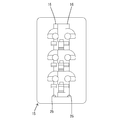
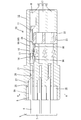
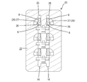
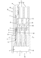
- Diagram showing part of the in-vehicle network Top view of joint terminal The perspective view which shows the connection condition of the joint terminal and female terminal after being twisted Sectional view of the joint connector with the joint terminal and female terminal connected Bottom view of housing Same right side view Same left side view Flat section of housing Front sectional view showing a state in which the joint terminal is inserted shallowly in the first terminal accommodating portion of the housing AA line sectional view of FIG. Front sectional view showing a state in which the joint terminal is inserted to the intermediate position in the first terminal accommodating portion of the housing. BB sectional view of FIG. Front sectional view showing a state where the joint terminal is inserted to the normal depth in the first terminal accommodating portion of the housing. CC sectional view of FIG. The perspective view which shows a tab approach path and a cam part typically Same front view
- each tab terminal is formed with a follower portion projecting, and each tab entry path is formed with a spiral cam portion communicating around its axis,
- the cam portion guides the follower portion as the joint terminal is incorporated into the first terminal accommodating portion, twists and deforms each tab terminal around its axis, and each tab terminal is moved to its plate.
- the elastic contact piece is formed so as to be contactable in the surface direction. According to such a configuration, when the joint terminal is incorporated into the first terminal accommodating portion of the housing, each tab terminal is inserted along the tab entry path, and the follower portion formed on the tab terminal is the tab entry path.
- the cam portion abuts the surface of the follower portion opposite to the twisting direction to the inner surface of the cam portion. It is preferable that the tab terminal is formed so as to be restricted from returning in the direction opposite to the twisting direction. According to such a configuration, since the spring back does not occur after the tab terminal is twisted, variation in the twist angle due to the spring back can be effectively avoided.
- the housing at least a pair of the first terminal accommodating portions are provided, the joint terminals are respectively incorporated therein, and the female terminals are connected to the tab terminals of the joint terminals that form a pair.
- the pair of female terminals are incorporated into the corresponding cavity pair in each of the second terminal accommodating portions provided in at least one pair in the housing,
- the bending direction of the lances may be set in a direction along the arrangement direction of the cavities constituting the second terminal accommodating portions. According to such a configuration, the pair of cavities in which the female terminal pairs connected to the twisted pair wires are accommodated belong to the paired second terminal accommodating portions.
- the bending direction of the lances arranged in the cavities is a direction along the direction in which the cavities constituting the second terminal accommodating portion are arranged. That is, since the lances are not arranged in the arrangement direction of the cavity pairs that accommodate the female terminal pairs connected to the twisted pair wires, the pitch between the cavity pairs can be reduced. Therefore, since the female terminal pair can be accommodated while keeping the distance between the twisted pair wires short, the noise reduction effect is not impaired.
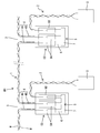
- FIG. 1 shows a part of an in-vehicle network called CAN (Control Area Network), and a plurality of electronic control units U can communicate with each other via a wire harness WH.
- CAN Control Area Network
- the wire harness WH includes a main line 1 and branch lines 2 that branch from the main line 1 at a plurality of branch points 3 and are connected to the electronic control units U at the respective branch destinations. Moreover, the trunk line 1 and each branch line 2 are comprised by the twisted pair wire which twisted the two electric wires W in a pair.
- a detour path 4 is formed at each branch point 3 toward the joint connector CO.
- the forward path 4A and the return path 4B in each detour path 4 are relayed in the joint connector CO and branched to each electronic control unit U.
- joint terminal see Fig. 2
- a pair of joint terminals 5 shown in FIG. 2 is accommodated in the joint connector CO (only one joint terminal 5 is shown in FIG. 1).
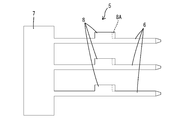
- the joint terminal 5 is made of a conductive metal, and is formed of three tab terminals 6 arranged in parallel in the width direction and a flat plate-like connecting piece 7 that connects end portions of the tab terminals 6.
- the electric wires W paired with the twisted pair wires described above are connected to the tab terminals 6 that are paired between the joint terminals 5 via female terminals 9A and 9B, respectively.
- a substantially rectangular follower portion 8 is formed on one side edge in the length direction of each tab terminal 6 so as to protrude.
- a chamfered portion 8A having a curved surface is formed at the front edge portion of each follower portion 8. The chamfered portion 8A is for smooth entry into a cam portion 27 described later.
- the joint terminal 5 is formed by stamping a flat base material with a press, and therefore, both side edges of the tab terminal 6 have broken surfaces.
- FIG. 2 when the tab terminal 6 is punched by a press, the plate surface (the front surface and the back surface shown in FIG. 2) and the plate surface of the connecting piece 7 are flush with each other.
- FIG. 3 the tab terminal 6 is twisted by 90 degrees around its axis, so that the plate surface of the connecting piece 7 and the tab terminal 6 are connected to each other.
- the plate surface is in a substantially perpendicular positional relationship. This will be described in detail later.
- the same female terminals 9A and 9B are used for the main line and the branch line.
- the female terminals 9A and 9B are also formed by punching a conductive metal plate material with a press and bending it into a predetermined shape.
- the female terminals 9A and 9B are composed of a rectangular tube-shaped terminal connecting portion 10 into which the tab terminal 6 can be inserted, and a wire connecting portion 11 arranged at the rear portion thereof.
- the electric wire connecting portion 11 further includes a wire barrel 11A for caulking the core wire exposed at the end of the electric wire (each electric wire constituting the twisted pair wire) and an insulation barrel 11B for caulking the covering portion of the electric wire W.
- the terminal connection portion 10 is formed by being bent into a rectangular tube shape, and the ceiling surface is a double wall.
- the outer surface side of the ceiling surface of the terminal connecting portion 10 is cut out at the central portion in the longitudinal direction and has a single structure.
- a pair of protrusions 12A and 12B are formed so as to protrude with the notch portion interposed between the front and rear. Both protrusions 12A and 12B have a function as a stabilizer, and the protrusion 12A on the front side also has a function of locking with a lance 13 described later.
- an elastic contact piece 14 is formed in the terminal connection portion 10 for electrical connection with each tab terminal 6 of the joint terminal 5.
- the elastic contact piece 14 is formed to extend rearward in a cantilevered manner, and can be bent in a direction opposite to the direction in which the protrusions 12A and 12B protrude. In other words, the elastic contact piece 14 is bent along the bending direction of the lance 13 (X direction: see FIGS. 4 and 6).
- the housing 15 is made of synthetic resin, and has a pair of first housing portions 16 (in FIG. 4, housing portions located on the left side in the housing, in FIG. Only the first accommodating portion 16 is shown), and a pair of female terminals for accommodating a total of three pairs of female terminals (two pairs of female terminals for main line 9A and one pair of female terminals for branch line 9B).
- a two-terminal accommodating portion 17 is formed (in FIG. 4, the accommodating portion is located on the right side in the housing 15, and only the second terminal accommodating portion 17 on one side is shown in FIG. 4).
- Each of the second terminal accommodating portions 17 includes a total of three cavities 18 each accommodating two female main terminals 9A and one branch female terminal 9B.
- the female terminals (the main female terminal 9 ⁇ / b> A and the branch female terminal 9 ⁇ / b> B) connected to the two electric wires W constituting the twisted pair wire are connected to each pair of second terminal accommodating portions. These are accommodated in cavities 18 that are juxtaposed in the horizontal direction (Y direction in the figure). As shown in the figure, in the cavities 18 constituting each second terminal accommodating portion 17, the pitch in the Y direction is set to be narrower than the pitch in the X direction.
- an insertion hole 20 for penetrating the tab terminal 6 is opened in the boundary wall 19 between each second terminal accommodating portion 17 and the corresponding first terminal accommodating portion 16, and When the lance 13 is formed, a die-cutting hole 21 is formed for enabling die-cutting toward the first terminal accommodating portion 16 side.
- a lance 13 that extends in a cantilevered manner toward the front is disposed inside each cavity 18 and in the front portion (a portion near the first terminal housing portion 16).
- Each lance 13 is formed to be deflectable along the X direction in FIG. The lance 13 prevents the female terminals 9A and 9B from coming off by elastically locking with the protrusion 12A on the front side of the female terminals 9A and 9B.
- a retainer mounting hole 22 is opened on one side surface of the housing 15.
- the retainer mounting hole 22 is formed so as to communicate with all the cavities 18.
- the retainer 23 mounted in the retainer mounting hole 22 has locking projections 24 that can be locked at the rear ends of the terminal connecting portions 10 of the female terminals 9A and 9B.
- the retainer 23 is held on the housing 15 at two positions, a temporary locking position and a main locking position.
- each locking projection 24 stands by outside the entry path of the female terminals 9A, 9B, so that each female terminal 9A, 9B can be inserted into and removed from the cavity 18. In the locking position, each locking projection 24 can be locked into the rear end of the terminal connecting portion 10 by entering the entry path of the female terminals 9A and 9B.
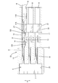
- the first terminal accommodating portion 16 has a two-stage arrangement along the Y direction.
- a connection piece accommodating portion 25 for accommodating the connection pieces 7 of both joint terminals 5 is formed at the inlet portions of both the first terminal accommodation portions 16.
- the opening width of the connecting piece housing portion 25 is formed slightly narrower than the width of the connecting piece 7 of the corresponding joint terminal 5. Therefore, in a state where the joint terminal 5 is accommodated in the first terminal accommodating portion 16, the connecting piece 7 is abutted against the inner wall of the first terminal accommodating portion 16 at the front end edge and is pressed into the connecting piece accommodating portion 25. The whole is prevented from being pulled out.
- each tab entry path 26 is formed in parallel along the X direction. Each tab terminal 6 can be inserted. Each tab entry path 26 is formed straight along the front-rear direction, and each tab terminal 6 of the joint terminal 5 can be inserted thereinto. Each tab entry path 26 is formed straight along the front-rear direction and is substantially coaxial with the corresponding cavity 18. The entrance portion of each tab entry path 26 is formed in a state communicating with the connecting piece housing portion 25. The front end of each tab entry path 26 opens to the boundary wall 19 as the insertion hole 20 described above.
- the tab approach path 26 is formed in a substantially circular hole shape having a hole diameter larger than the outer diameter of the tab terminal 6 as shown in FIG.
- a cam portion 27 is formed in communication with each tab entry path 26 over its entire length.
- the cam portion 27 is formed with a thickness substantially equal to or slightly larger than the plate thickness of the follower portion 8, and can allow the follower portion 8 to enter.
- the cam portion 27 is a straight portion 28 that is straight along the front-rear direction until reaching the position slightly inward from the entrance (the rear end of the housing 15) of the first terminal accommodating portion 16. It has become.
- a spiral portion 29 is formed in the length range on the front side of the straight portion 28.
- the spiral portion 29 is formed so as to rotate spirally around the axis of the tab entry path 26. In the case of this embodiment, the turning angle from the start end to the end of the spiral is approximately 90 degrees.
- the cam portion 27 is formed so as to reach the front end from the end of the spiral while maintaining the cross-sectional shape at the end of the spiral.
- the turning direction in which the spiral is drawn is opposite.
- the turning direction is clockwise, whereas the first terminal housing portion 16 positioned on the lower side. Then, it is counterclockwise.
- each tab terminal 6 initially advances along the straight portion 28 of the cam portion 27. Does not occur.
- the follower portion 8 enters the spiral portion 29 of the cam portion 27, the front end portion of the connecting piece 7 of the joint terminal 5 enters the connecting piece housing portion 25 and is in the thickness direction.
- each tab terminal 6 is twisted and deformed around each axis along with the movement of the follower portion 8 along the spiral path of the spiral portion 29.
- the follower portion 8 has a relationship that is approximately 90 degrees out of phase with the connecting piece 7.
- the plate surface direction of the tab terminal 6 is the direction along the Y direction, but the joint terminal 5 is the first terminal accommodating portion 16.
- the plate surface direction of the tab terminal 6 is converted to the X direction.
- the follower portion 8 is located at the front end portion of the spiral portion 29 and is sandwiched from the plate thickness direction by the opposing inner wall surface of the spiral portion 29. It is regulated not to cause a return (springback) from the deformed state.
- each tab terminal 6 of both joint terminals 5 is inserted into the corresponding tab entry path 26, and at the same time, each follower portion 8 is inserted into the straight portion 28 of the corresponding cam portion 27 (see FIGS. 9 and 10).
- each tab terminal 6 was initially oriented in the Y direction, which is the same direction as the plate surface direction of the connecting piece 7, but was twisted 90 degrees when the joint terminal 5 was accommodated. It is converted in the X direction.
- the trunk line 1 has a detour path 4 for each branch point 3 to each electronic control unit U.
- Each detour path 4 includes an outward path 4A toward the joint connector CO and a return path 4B that returns from the joint connector CO to the main line 1 again.
- the main female terminals 9A are respectively connected to the ends of the two electric wires W constituting the twisted pair wire serving as the forward path 4A and the ends of the two electric wires W constituting the twisted pair wire serving as the return path 4B.
- branch line female terminals 9B are respectively connected to the ends of the two electric wires W constituting the twisted pair wires that are branch lines connected to the respective electronic control units U.
- the pair of trunk female terminals 9A connected to each end of the twisted pair wire constituting the forward path 4A of the detour path 4 is the second pair that is paired in the Y direction in FIG. 1 is inserted into a cavity 18 at the left end of the terminal accommodating portion 17 (in FIG. 1, the cavity 18 is not shown) (in FIG. 1, only one main female terminal 9A and one joint terminal 5 are shown for convenience of drawing). It is shown).
- the pair of trunk female terminals 9A connected to the return path 4B of the detour path 4 is respectively inserted into the cavities 18 in the center of the second terminal accommodating portions 17 that are paired in the Y direction.
- the pair of branch line female terminals 9B is inserted into the cavity 18 at the right end of the second terminal accommodating portion 17 that is paired in the Y direction. As described above, when the female terminals 9A and 9B are inserted into the cavity 18, the retainer 23 is held at the temporary locking position.
- the primary locking by the lance 13 is performed.
- the retainer 23 is moved from the temporary locking to the final locking position, the locking protrusions 24 of the retainer 23 are locked to the rear ends of the corresponding terminal terminals 10 of the female terminals 9A and 9B.
- the female terminals 9 ⁇ / b> A and 9 ⁇ / b> B are double-stopped together with the lance 13.
- the tab terminals 6 of the corresponding joint terminals 5 are inserted into the terminal connection portions of the female terminals 9A and 9B.
- the tab terminal 6 is slidably contacted while bending the elastic contact piece 14 to be in an electrically connected state.
- the elastic contact piece 14 since the elastic contact piece 14 is in contact with the plate surface rather than the fracture surface of the tab terminal 6, it is not damaged from the fracture surface.
- connection between the branch points 3 of the main line 1 is made by relaying the joint terminal 5 and the main line female terminal 9A for the forward path and the return path in the detour path 4.
- the whole trunk line 1 is comprised by connecting between the branch points 3 in this way.
- the joint terminal 5 and the branch line female terminal 9 ⁇ / b> B are connected at each branch point 3, whereby each electronic control unit U is branched from the main line 1 and connected. In this way, a connection is made at each branch point 3 to construct an in-vehicle network, and communication between the electronic control units U is possible.
- the pair of female terminals 9A and 9B connected to the twisted pair wires constituting the main line 1 and the branch line 2 are brought close to the inside of the housing 15, that is, the corresponding cavity 18
- the interval (interval in the Y direction) can be reduced. Therefore, the high noise removal function of the twisted pair wire can be maintained as it is even at the connection site with the connector.
- the tab terminal 6 is twisted approximately 90 degrees around the axis, so that the elastic contact pieces 14 of the female terminals 9A and 9B are connected to the joint terminal 5 Therefore, the elastic contact piece 14 can be protected from damage without contacting the broken surface of the tab terminal 6.
- the twisting of the tab terminal 6 is not performed in advance, it is performed in accordance with the insertion operation of the joint connector CO into the housing 15, so that the manufacturing efficiency of the joint connector CO is increased by the absence of prior processing. Can be increased.
- the follower portion 8 is located at the front end portion of the spiral portion 29 in a state where the insertion operation of the joint terminal 5 is completed, and is sandwiched from the plate thickness direction by the opposing inner wall surface of the spiral portion 29. Therefore, each tab terminal 6 does not cause a return (springback) from the twisted state. Therefore, the effect that the tab terminal 6 can be stably in contact with the plate surface of the elastic contact piece 14 of the corresponding female terminal 9A, 9B is also obtained.
- the present invention is not limited to the embodiments described with reference to the above description and drawings.
- the following embodiments are also included in the technical scope of the present invention.
- the tab terminal is twisted in the process of assembling the joint terminal into the first terminal accommodating portion. Instead, the tab terminal is incorporated before being incorporated into the first terminal accommodating portion. You may make it perform the process which adds a twist.
- the joint connector is applied to the in-vehicle network is shown, but the application should not be limited.
Landscapes
- Engineering & Computer Science (AREA)
- Computer Networks & Wireless Communication (AREA)
- Signal Processing (AREA)
- Connector Housings Or Holding Contact Members (AREA)
Abstract
キャビティ間ピッチを詰めつつジョイントコネクタの製造効率を高める。 ジョイント端子(5)をハウジング(15)の第1端子収容部(16)に組み込む過程で、ジョイント端子(5)のタブ端子(6)はハウジング(15)内に形成されたタブ進入路(26)に沿って前進する。タブ進入路(26)にはその軸線回りに螺旋状にカム部(27)が形成され、タブ端子(6)がタブ進入路(26)を前進することに伴って、タブ端子(6)の途中に形成されたフォロア部(8)がカム部(27)によって案内されるため、タブ端子(6)は軸線回りに捻りが加えられる。これにより、雌端子(9A,9B)の弾性接触片(14)はタブ端子(6)の板面方向と対面して接続がとられる。
Description
本発明はジョイントコネクタに関するものである。
従来より、自動車にはCANと呼ばれる車載ネットワークが搭載され、複数のノード(電子制御ユニット)同士が通信用伝送路を構成するワイヤハーネスを通じて通信を行うようになっている。そのような技術を開示するものとして下記特許文献1を挙げることができる。
ここには、ワイヤハーネスの複数の通信線をジョイントコネクタを介して接続する形式のものが開示されている。コネクタ内には、複数のタブ端子が突出するジョイント端子が上下二段に取り付けられており、幹線の分岐ポイント間を雌端子を介して接続したり、あるいは幹線から分岐する分岐線を雌端子を介して接続するようになっている。通信線としてはノイズの影響を受けにくくするためにツイストペア線が使用されている。このうち、一方の通信線はいずれか一方の段のジョイント端子に接続され、対応する他方の通信線は他方の段のジョイント端子に接続される。
ところで、上記したジョイントコネクタにおいて、ツイストペア線におけるペアとなる通信線に接続された各端子を収容するキャビティ間の間隔はできるだけ接近していることが好ましい。間隔が広いと、ノイズ低減の効果が損なわれてしまうからである。その対策としては、ツイストペア線に対応する両キャビティ内に形成されるランスの撓み方向(X方向)を、両キャビティの並び方向(Y方向)と直交する方向になるよう、ランスの配置を変更することが考えられる。仮に、同方向にしてしまうと、キャビティは端子の収容空間の高さにランスの撓み空間が積み重なってしまい、その分、キャビティ間のピッチが拡大してしまうからである。なお、各雌端子の内部には対応するタブ端子との接続のための弾性接触片が形成されており、その撓み方向はランスの撓み方向と同方向である、X方向となる。
上記の対策構造にすると、ジョイント端子の各タブ端子の並び方向もX方向となるため、各タブはそれらの並び方向でもって対応する弾性接触片と接することになる。すなわち、各タブ端子は母材から切り出した際の破断面が弾性接触片と対向して接触し合うことになる。
しかし、これでは、端子同士の接続(摺接)する際に、弾性接触片が損傷してめっきが剥がれたりすることが懸念される。
本発明は上記のような事情に基づいて完成されたものであって、弾性接触片の撓み方向がタブ端子の並び方向に沿う方向であっても、タブ端子の破断面が弾性接触片と対向しないようにして弾性接触片を保護することができるジョイントコネクタを提供することを目的とする。
本発明のジョイントコネクタは、連結片とこの連結片から並列して突出する複数のタブ端子とが形成されたジョイント端子と、各タブ端子が差し込み可能で内部にはタブ端子と弾性的に接触するための撓み可能な弾性接触片が形成された端子接続部を有する複数の雌端子金具と、ジョイント端子を組み込み可能で各タブ端子が挿入される複数のタブ進入路が形成された第1端子収容部と、各タブ進入路と同軸で対向し雌端子金具が挿入可能であり、内部には各雌端子金具に弾性的に係止する撓み可能なランスが形成された複数のキャビティを有する第2端子収容部とが形成されたハウジングとを備え、弾性接触片の撓み方向がタブ端子の並び方向と同一方向であるジョイントコネクタであって、ジョイント端子における各タブ端子はそれぞれの軸線周りに捻られるようにして形成されて、各タブ端子の板面方向が連結片の板面方向と略直角であり、かつ弾性接触片の撓み方向と略同方向となっていることを特徴とする。
本発明のジョイントコネクタによれば、第1端子収容部内に組込まれたジョイント端子の各タブ端子に対し、第2端子収容部内に挿入された雌端子とが接続されることで、各雌端子はジョイント端子を介してジョイントされる。この場合において、雌端子の弾性接触片が、タブ端子に対し板面方向でなくこれと直交する方向、つまり破断面となる方向で接するようなハウジング構造となっていると、接続の過程で弾性接触片が破断面によって損傷されてしまう懸念がある。しかし、本発明によれば、このようなハウジング構造であっても、ジョイント端子の各タブ端子が軸線周りに捻られて連結片の板面方向と略直交するようになっているため、各タブ端子は雌端子の弾性接触片と板面方向でもって接することができる。したがって、弾性接触片をタブ端子の破断面による損傷から確実に保護することができる。
本発明における好ましい実施の形態を説明する。
(1)本発明のジョイントコネクタは、前記各タブ端子にはフォロア部が張り出し形成される一方、前記各タブ進入路にはその軸線周りに螺旋状のカム部が連通して形成され、かつこのカム部は、前記ジョイント端子を前記第1端子収容部へ組み込むことに伴って前記フォロア部を案内して、前記各タブ端子をその軸線周りに捻り変形させて、前記各タブ端子を、その板面方向で前記弾性接触片に接触可能に形成されるようにすることが好ましい。
このような構成によれば、ジョイント端子をハウジングの第1端子収容部へ組み込む際に、各タブ端子はタブ進入路に沿って挿入されるとともに、タブ端子に形成されたフォロア部がタブ進入路に形成されたカム部の螺旋経路に案内されながら前進する。タブ端子はこの過程で軸線周りの捻り力が加えられ、ジョイント端子の組み込みが完了すると、各タブ端子の板面方向は連結片の板面方向と略直交する位置関係となる。その結果、タブ端子はその板面方向で雌端子の弾性接触片と接する。以上のように、ジョイント端子の組み込み動作に連動してタブ端子の板面方向を変更することができるため、雌端子に対し事前に捻り加工を行う場合に比べて製造効率を高めることができる。
(1)本発明のジョイントコネクタは、前記各タブ端子にはフォロア部が張り出し形成される一方、前記各タブ進入路にはその軸線周りに螺旋状のカム部が連通して形成され、かつこのカム部は、前記ジョイント端子を前記第1端子収容部へ組み込むことに伴って前記フォロア部を案内して、前記各タブ端子をその軸線周りに捻り変形させて、前記各タブ端子を、その板面方向で前記弾性接触片に接触可能に形成されるようにすることが好ましい。
このような構成によれば、ジョイント端子をハウジングの第1端子収容部へ組み込む際に、各タブ端子はタブ進入路に沿って挿入されるとともに、タブ端子に形成されたフォロア部がタブ進入路に形成されたカム部の螺旋経路に案内されながら前進する。タブ端子はこの過程で軸線周りの捻り力が加えられ、ジョイント端子の組み込みが完了すると、各タブ端子の板面方向は連結片の板面方向と略直交する位置関係となる。その結果、タブ端子はその板面方向で雌端子の弾性接触片と接する。以上のように、ジョイント端子の組み込み動作に連動してタブ端子の板面方向を変更することができるため、雌端子に対し事前に捻り加工を行う場合に比べて製造効率を高めることができる。
(2)また、前記カム部は、前記ジョイント端子が前記第1端子収容部に正規に組み込まれたときに、前記フォロア部における前記捻り方向と反対側の面を前記カム部の内面に当接させて前記タブ端子が捻り方向と反対方向への戻るのを規制可能に形成されていることが好ましい。
このような構成によれば、タブ端子が捻りを加えられた後にスプリングバックを生じることがないため、スプリングバックに起因した捻り角度のばらつきを有効に回避することができる。
このような構成によれば、タブ端子が捻りを加えられた後にスプリングバックを生じることがないため、スプリングバックに起因した捻り角度のばらつきを有効に回避することができる。
(3)さらに、前記ハウジング内には、前記第1端子収容部が少なくとも一対設けられて、それぞれに前記ジョイント端子が組込まれ、かつ対となる前記ジョイント端子の各タブ端子に接続される雌端子の対はツイストペア線に接続され、対となる前記雌端子は前記ハウジングに少なくとも一対設けられた各第2端子収容部において、対応する前記キャビティ対の内部に組込まれるようになっており、さらに、前記各ランスの撓み方向は前記各第2端子収容部を構成する各キャビティの並び方向に沿う方向に設定されているとよい。
このような構成によれば、ツイストペア線に接続された雌端子対が収容されるキャビティのペアは、対となる第2端子収容部にそれぞれ属している。そして、これらキャビティ内に配されたランスの撓み方向は第2端子収容部を構成する各キャビティの並び方向に沿う方向としている。つまり、ツイストペア線に接続された雌端子対を収容するキャビティ対の並び方向にランスを配置していないため、このキャビティ対の間のピッチを詰めることができる。したがって、ツイストペア線の間隔を短く保ったまま雌端子対を収容することができるため、ノイズ低減の効果を損なうことがない。
このような構成によれば、ツイストペア線に接続された雌端子対が収容されるキャビティのペアは、対となる第2端子収容部にそれぞれ属している。そして、これらキャビティ内に配されたランスの撓み方向は第2端子収容部を構成する各キャビティの並び方向に沿う方向としている。つまり、ツイストペア線に接続された雌端子対を収容するキャビティ対の並び方向にランスを配置していないため、このキャビティ対の間のピッチを詰めることができる。したがって、ツイストペア線の間隔を短く保ったまま雌端子対を収容することができるため、ノイズ低減の効果を損なうことがない。
<実施例>
次に、本発明のジョイントコネクタを具体化した実施例について、図面を参照しつつ説明する。
次に、本発明のジョイントコネクタを具体化した実施例について、図面を参照しつつ説明する。
(車載ネットワークの概要)
図1は、CAN(Control Area Network)と呼ばれる車載ネットワークの一部を示すものであり、複数の電子制御ユニットU同士がワイヤハーネスWHを介して通信が可能になっている。
図1は、CAN(Control Area Network)と呼ばれる車載ネットワークの一部を示すものであり、複数の電子制御ユニットU同士がワイヤハーネスWHを介して通信が可能になっている。
ワイヤハーネスWHは、幹線1と、この幹線1から複数の分岐ポイント3において分岐し、それぞれの分岐先で各電子制御ユニットUに接続される分岐線2とから構成されている。また、幹線1及び各分岐線2は二本の電線Wを対で撚り合せたツイストペア線によって構成されている。
幹線1は、各分岐ポイント3においてジョイントコネクタCOへ向けて迂回経路4が形成されている。各迂回経路4における往路4Aと復路4Bとは、ジョイントコネクタCO内において中継され、かつ各電子制御ユニットUへの分岐がなされている。
(ジョイント端子:図2参照)
ジョイントコネクタCO内には、図2に示すジョイント端子5が一対収容されている(図1では一方のジョイント端子5のみが示されている。)。ジョイント端子5は導電金属製であり、幅方向に並列する3本のタブ端子6とこれらタブ端子6の端部を連結する平板状の連結片7とから形成されている。上記したツイストペア線で対をなす電線Wは、両ジョイント端子5間で対となるタブ端子6に対しそれぞれ雌端子9A,9Bを介して接続される。
ジョイントコネクタCO内には、図2に示すジョイント端子5が一対収容されている(図1では一方のジョイント端子5のみが示されている。)。ジョイント端子5は導電金属製であり、幅方向に並列する3本のタブ端子6とこれらタブ端子6の端部を連結する平板状の連結片7とから形成されている。上記したツイストペア線で対をなす電線Wは、両ジョイント端子5間で対となるタブ端子6に対しそれぞれ雌端子9A,9Bを介して接続される。
各タブ端子6の長さ方向の一方の側縁には略方形状のフォロア部8が張り出し形成されている。各フォロア部8の前縁部には表面が湾曲状をなす面取り部8Aが形成されている。面取り部8Aは、後述するカム部27への進入を円滑にするためのものである。
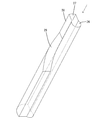
ジョイント端子5は、平板の母材からプレスによって打ち抜いて形成したものであり、したがって、タブ端子6の両側縁は破断面となっている。タブ端子6はプレスによって打ち抜かれたときの形態は、図2に示すように、各タブ端子6の板面(同図に示す表面と裏面)と連結片7の板面とは同一平面をなす形態であるが、ジョイントコネクタCOに組込まれた後の形態は、図3に示すように、各タブ端子6がその軸線周りに90度捻られて、連結片7の板面とタブ端子6の板面とが略直交した位置関係となっている。このことについては、後に詳述する。
(雌端子:図3参照)
雌端子9A,9Bは、幹線用と分岐線用のそれぞれに関して同一のものが使用されている。雌端子9A,9Bも導電金属製の板材をプレスにて打ち抜いた後に、所定形状に曲げ加工したものである。雌端子9A,9Bは、タブ端子6が差し込み可能な角筒状の端子接続部10と、その後部に配された電線接続部11とからなっている。電線接続部11は、さらに電線(ツイストペア線を構成する各電線)の端部に露出する芯線をかしめ付けるワイヤバレル11Aと、電線Wの被覆部分をかしめ付けるインシュレーションバレル11Bとからなっている。
雌端子9A,9Bは、幹線用と分岐線用のそれぞれに関して同一のものが使用されている。雌端子9A,9Bも導電金属製の板材をプレスにて打ち抜いた後に、所定形状に曲げ加工したものである。雌端子9A,9Bは、タブ端子6が差し込み可能な角筒状の端子接続部10と、その後部に配された電線接続部11とからなっている。電線接続部11は、さらに電線(ツイストペア線を構成する各電線)の端部に露出する芯線をかしめ付けるワイヤバレル11Aと、電線Wの被覆部分をかしめ付けるインシュレーションバレル11Bとからなっている。
端子接続部10は角筒状に折り曲げられて形成され、天井面は二重壁となっている。端子接続部10の天井面のうち外面側は、長手方向の中央部において切り欠かれ、一重の構造となっている。端子接続部10における天井面の外面側はこの切欠き部分を前後に挟んで、一対の突部12A,12Bが突出形成されている。両突部12A,12Bは共にスタビライザとしての機能を有し、前側の突部12Aは後述するランス13と係止する機能も有している。
また、図4等に示すように、端子接続部10の内部にはジョイント端子5の各タブ端子6と電気的な接続を行うための弾性接触片14が形成されている。同図に示すように、弾性接触片14は後方へ片持ち状に延出して形成され、両突部12A,12Bの突出する方向とは反対方向への撓みが可能である。換言すれば、弾性接触片14の撓みはランス13の撓み方向(X方向:図4、図6参照)に沿って行なわれるようになっている。
(コネクタのハウジング:主として図4~図8参照)
ハウジング15は合成樹脂製であり、内部には一対のジョイント端子5を収容するための一対の第1収容部16(図4ではハウジング内の左側に位置する収容部であり、同図では片側の第1収容部16のみが示されている。)と、計3対の雌端子(2対の幹線用雌端子9Aと1対の分岐線用雌端子9B)を収容するための1対の第2端子収容部17とが形成されている(図4ではハウジング15内の右側に位置する収容部であり、同図では片側の第2端子収容部17のみが示されている。)。各第2端子収容部17は二つの幹線用雌端子9Aと一つの分岐線用雌端子9Bとを収容するキャビティ18を計3室ずつ備えている。
ハウジング15は合成樹脂製であり、内部には一対のジョイント端子5を収容するための一対の第1収容部16(図4ではハウジング内の左側に位置する収容部であり、同図では片側の第1収容部16のみが示されている。)と、計3対の雌端子(2対の幹線用雌端子9Aと1対の分岐線用雌端子9B)を収容するための1対の第2端子収容部17とが形成されている(図4ではハウジング15内の右側に位置する収容部であり、同図では片側の第2端子収容部17のみが示されている。)。各第2端子収容部17は二つの幹線用雌端子9Aと一つの分岐線用雌端子9Bとを収容するキャビティ18を計3室ずつ備えている。
図6に示すように、ツイストペア線を構成する両電線Wに接続された対となる雌端子(幹線用雌端子9A及び分岐線用雌端子9B)は、対をなす各第2端子収容部において、図示左右方向(同図ではY方向)で並列するキャビティ18内に収容される。同図に示されるように、各第2端子収容部17を構成するキャビティ18において、Y方向に関するピッチはX方向に関するピッチよりも狭くなるように設定されている。
また、図4等に示すように、各第2端子収容部17と対応する両第1端子収容部16との境界壁19にはタブ端子6を貫通させるための挿通孔20が開口するとともに、ランス13を成形する際に第1端子収容部16側への型抜きを可能にするための型抜き孔21が開口している。
また、各キャビティ18の内部であって、前部(第1端子収容部16寄りの部位)には、前方へ向けて片持ち状に延出するランス13が配されている。各ランス13は図6におけるX方向に沿って撓み可能に形成されている。ランス13は、雌端子9A,9Bの前側の突部12Aと弾性的に係止することで雌端子9A,9Bの抜け止めを行う。
さらに、図5に示すように、ハウジング15における一側面にはリテーナ装着孔22が開口している。リテーナ装着孔22は全キャビティ18に連通するようにして形成されている。一方、このリテーナ装着孔22に装着されるリテーナ23は、各雌端子9A,9Bの端子接続部10の後端にそれぞれ係止可能な係止突起24が形成されている。また、リテーナ23は詳細には図示しないが、ハウジング15に対して仮係止位置と本係止位置の二位置で保持されるようになっている。仮係止位置では、各係止突起24が雌端子9A,9Bの進入経路の外側に待機することで、各雌端子9A,9Bがキャビティ18に対して抜き差し自在となっているが、本係止位置では、各係止突起24が雌端子9A,9Bの進入経路内に突入することで、端子接続部10の後端に係止可能である。
次に、第1端子収容部16について説明すると、図7に示すように、第1端子収容部16はY方向に沿った二段の配置となっている。図13等に示すように、両第1端子収容部16の入口部分には両ジョイント端子5の連結片7が収容される連結片収容部25が形成されている。連結片収容部25の開口幅は、対応するジョイント端子5の連結片7の幅より僅かに狭めに形成されている。したがって、ジョイント端子5が第1端子収容部16に収容された状態では、連結片7は前端縁が第1端子収容部16の奥壁に突き当てられるとともに、連結片収容部25に対し圧入気味に嵌め入れられることで、全体の抜け止めがされている。
図7、図9、図10に示すように、両第1端子収容部16内にはそれぞれ3つのタブ進入路26がX方向に沿って並列して形成されており、それぞれはジョイント端子5の各タブ端子6を差し込み可能となっている。各タブ進入路26はそれぞれ前後方向に沿って真っ直ぐに形成され、それぞれはジョイント端子5の各タブ端子6を差し込み可能となっている。各タブ進入路26はそれぞれ前後方向に沿って真っ直ぐに形成され、対応するキャビティ18とほぼ同軸をなしている。各タブ進入路26の入口部分は連結片収容部25に連通した状態で形成されている。各タブ進入路26の前端は前述した挿通孔20として境界壁19に開口している。タブ進入路26は、図7等に示すように、タブ端子6の外径より大きな孔径を有する略円形の孔形状にて形成されている。
図15~図16に示すように、各タブ進入路26にはその全長に亘ってカム部27が連通して形成されている。カム部27はフォロア部8の板厚と略等しいか、それよりもやや大きめの厚みをもって形成されており、フォロア部8を進入させうる。図15、図16に示すように、カム部27は第1端子収容部16の入口(ハウジング15の後端)からやや奥方に入り込んだ位置に至るまでは前後方向に沿って真っ直ぐなストレート部28となっている。そして、ストレート部28より前部側の長さ範囲には螺旋部29が形成されている。螺旋部29はタブ進入路26の軸線周りに螺旋状に旋回するようにして形成されている。本実施例の場合、螺旋の始端から終端に至るまでの旋回角度は略90度である。カム部27は螺旋の終端から先も、螺旋の終端における断面形状を維持したまま前端に至るように形成されている。
但し、Y方向で対をなす第1端子収容部16間においては、螺旋を描く旋回方向は逆向きとなっている。例えば、図10、図12、図14において、Y方向で上段側に位置する第1端子収容部16では、旋回方向が時計周りであるのに対し、下段側に位置する第1端子収容部16では、反時計周りとなっている。
かくして、ジョイント端子5が第1端子収容部16に差し込まれていく過程で、各タブ端子6のフォロア部8は当初、カム部27のストレート部28に沿って前進するため、タブ端子6の変形は生じない。しかし、図11に示すように、フォロア部8がカム部27の螺旋部29に進入した時点では、ジョイント端子5の連結片7の前端部が連結片収容部25内に進入して板厚方向から挟持されているため、以後、フォロア部8が螺旋部29の螺旋経路に沿って移動することに伴って各タブ端子6はそれぞれの軸線周りに捻り変形させられる。この結果、フォロア部8は連結片7とは略90度位相がずれた関係となる。換言すれば、ジョイント端子5が第1端子収容部16に差し込まれる当初の時点では、タブ端子6の板面方向はY方向に沿う方向であったが、ジョイント端子5が第1端子収容部16への差込みが完了した時点では、タブ端子6の板面方向はX方向へと変換されることになる。
なお、ジョイント端子5の差し込み操作が完了した状態で、フォロア部8は螺旋部29の前端部に位置し、螺旋部29の対向する内壁面によって板厚方向から挟持された状態にあるため、捻り変形の状態からの戻り(スプリングバック)を生じることがないよう規制されている。
次に、ジョイントコネクタCOの製造手順の一例について説明する。まず、両ジョイント端子5を、第1端子収容部16内に収容する作業がなされる。その場合、両ジョイント端子5の各タブ端子6を対応するタブ進入路26へ差し込むと同時に、各フォロア部8を対応するカム部27のストレート部28へ差し込む(図9、図10参照)。
そのままジョイント端子5を押し込むと、図11に示すように、連結片7の前端部が連結片収容部25の入口部分に入り込むため、連結片7は連結片収容部25内の対向壁面によって板面方向から挟持される。一方、各フォロア部8が螺旋部29の入口部分に進入するため、ジョイント端子5の押込みに伴って、フォロア部8は螺旋部29の内面(カム面)からタブ端子6の軸芯周りに所定方向への捻り力を受ける。
そして、連結片7の前端が第1端子収容部16の奥壁に突き当てられると、ジョイント端子5の差込みが完了する。このときには、連結片7の長手方向両側縁が連結片収容部25内の対向壁に食い込み気味にして圧入されるため、ジョイント端子5全体が第1端子収容部16に対して抜け止め状態で収容される。一方、このときには各フォロア部8は螺旋部29の前端部に至っており、フォロア部8がここに至るまでの間に、各タブ端子6はその軸線周りに90度の捻りが加えられる。その結果、前述したように、各タブ端子6の板面は当初、連結片7の板面方向と同方向であるY方向を向いていたが、ジョイント端子5の収容完了時には90度捻られてX方向に変換されている。
次に、ジョイント端子5の各タブに対する幹線用雌端子9Aおよび分岐線用雌端子9Bとの接続について説明する。
図1に示すように、幹線1は各電子制御ユニットUへの分岐ポイント3毎に、迂回経路4を有している。各迂回経路4は、ジョイントコネクタCOに向かう往路4Aと、ジョイントコネクタCOから再び幹線1へと回帰する復路4Bとからなっている。往路4Aとなるツイストペア線を構成する両電線Wの端部、及び復路4Bとなるツイストペア線を構成する両電線Wの端部に対しそれぞれ幹線用雌端子9Aを接続しておく。また、各電子制御ユニットUに接続される分岐線となるツイストペア線を構成する両電線Wの端部に対しそれぞれ分岐線用雌端子9Bを接続しておく。
図1に示すように、幹線1は各電子制御ユニットUへの分岐ポイント3毎に、迂回経路4を有している。各迂回経路4は、ジョイントコネクタCOに向かう往路4Aと、ジョイントコネクタCOから再び幹線1へと回帰する復路4Bとからなっている。往路4Aとなるツイストペア線を構成する両電線Wの端部、及び復路4Bとなるツイストペア線を構成する両電線Wの端部に対しそれぞれ幹線用雌端子9Aを接続しておく。また、各電子制御ユニットUに接続される分岐線となるツイストペア線を構成する両電線Wの端部に対しそれぞれ分岐線用雌端子9Bを接続しておく。
そして、図1に示すようにして、迂回経路4の往路4Aを構成するツイストペア線の各端部に接続された幹線用雌端子9Aのペアは、図6でY方向で対となる両第2端子収容部17の図示左端のキャビティ18(図1において、キャビティ18は図示省略)内に差し込まれる(なお、図1では図面作成の便宜上、一方の幹線用雌端子9A及び一方のジョイント端子5のみが示されている)。同様にして、迂回経路4の復路4Bに接続された幹線用雌端子9Aのペアは、Y方向で対となる両第2端子収容部17の図示中央のキャビティ18内にそれぞれ差し込まれる。また、分岐線用雌端子9Bのペアは、Y方向で対となる両第2端子収容部17の図示右端のキャビティ18内に差し込まれる。なお、前述したように、各雌端子9A,9Bがキャビティ18内に挿入される際には、リテーナ23は仮係止位置に保持されている。
こうして、各雌端子9A,9Bが対応するキャビティ18内に差し込まれると、それぞれはランス13による一次係止がなされる。その後に、リテーナ23を仮係止から本係止位置に移動させると、リテーナ23の各係止突起24が対応する雌端子9A,9Bの端子接続部10の後端に係止する結果、各雌端子9A,9Bはランス13と併せて二重に抜け止めがされる。
上記のようにして各雌端子9A,9Bが対応するキャビティ18内に正規に挿入されると、各雌端子9A,9Bの端子接続部内に対応するジョイント端子5のタブ端子6が進入される。この過程で、タブ端子6は弾性接触片14を撓ませつつ摺接して電気的な接続状態となる。この間、弾性接触片14はタブ端子6の破断面ではなく板面と接するため、破断面から損傷を受けることはない。
以上のようにして、ジョイント端子5と迂回経路4における往路用及び復路用の幹線用雌端子9Aとが中継されることで、幹線1の分岐ポイント3間の接続がなされる。この要領で各分岐ポイント3間を接続することで、幹線1全体が構成される。また、各分岐ポイント3においてジョイント端子5と分岐線用雌端子9Bとが接続されることで、各電子制御ユニットUが幹線1から分岐して接続がなされる。この要領で、各分岐ポイント3で接続がなされることで車載ネットワークが構築され、電子制御ユニットU間での通信が可能となる。
以上のように、本実施例によれば、幹線1および分岐線2を構成する各ツイストペア線に接続された雌端子9A,9Bのペアを、ハウジング15内に接近した状態、つまり対応するキャビティ18間の間隔(Y方向の間隔)を詰めることができる。したがって、コネクタとの接続部位においても、ツイストペア線の持つ高いノイズ除去機能をそのまま保持することができる。また、このような構成を採用するにあたって、ランス13の位置を変更しても、タブ端子6を軸線周りに略90度捻るようにしたため、雌端子9A,9Bの弾性接触片14をジョイント端子5のタブ端子6の破断面と接することがなく、弾性接触片14を損傷から保護することができる。しかも、タブ端子6の捻り加工を事前に行っておくのではなく、ジョイントコネクタCOのハウジング15への挿入操作に伴って行うようにしたため、事前の加工がない分、ジョイントコネクタCOの製造効率を高めることができる。
さらに、本実施例によれば、ジョイント端子5の差し込み操作が完了した状態で、フォロア部8は螺旋部29の前端部に位置し、螺旋部29の対向する内壁面によって板厚方向から挟持された状態にあるため、各タブ端子6は捻り変形の状態からの戻り(スプリングバック)を生じることがないようになっている。したがって、タブ端子6は対応する雌端子9A,9Bの弾性接触片14の板面に対して安定的に接することができる、という効果も得られる。
<他の実施例>
本発明は上記記述及び図面によって説明した実施例に限定されるものではなく、例えば次のような実施例も本発明の技術的範囲に含まれる。
(1)上記実施例では、ジョイント端子を第1端子収容部に組込む過程で、タブ端子に捻りを加えるものであったが、これに代えて第1端子収容部への組み込み前に、タブ端子に捻りを加える加工を行うようにしてもよい。
(2)上記実施例では、ジョイントコネクタが車載ネットワークに適用された場合を示したが、用途は限定されるべきものではない。
本発明は上記記述及び図面によって説明した実施例に限定されるものではなく、例えば次のような実施例も本発明の技術的範囲に含まれる。
(1)上記実施例では、ジョイント端子を第1端子収容部に組込む過程で、タブ端子に捻りを加えるものであったが、これに代えて第1端子収容部への組み込み前に、タブ端子に捻りを加える加工を行うようにしてもよい。
(2)上記実施例では、ジョイントコネクタが車載ネットワークに適用された場合を示したが、用途は限定されるべきものではない。
5…ジョイント端子
6…タブ端子
7…連結片
8…フォロア部
9A…幹線用雌端子
9B…分岐線用雌端子
14…弾性接触片
15…ハウジング
16…第1端子収容部
17…第2端子収容部
26…タブ進入路
27…カム部
CO…ジョイントコネクタ
6…タブ端子
7…連結片
8…フォロア部
9A…幹線用雌端子
9B…分岐線用雌端子
14…弾性接触片
15…ハウジング
16…第1端子収容部
17…第2端子収容部
26…タブ進入路
27…カム部
CO…ジョイントコネクタ
Claims (4)
- 連結片とこの連結片から並列して突出する複数のタブ端子とが形成されたジョイント端子と、
前記各タブ端子が差し込み可能で内部には前記タブ端子と弾性的に接触するための撓み可能な弾性接触片が形成された端子接続部を有する複数の雌端子金具と、
前記ジョイント端子を組み込み可能で前記各タブ端子が挿入される複数のタブ進入路が形成された第1端子収容部と、前記各タブ進入路と同軸で対向し前記雌端子金具が挿入可能であり、内部には前記各雌端子金具に弾性的に係止する撓み可能なランスが形成された複数のキャビティを有する第2端子収容部とが形成されたハウジングとを備え、前記弾性接触片の撓み方向が前記タブ端子の並び方向と同一方向であるジョイントコネクタであって、
前記ジョイント端子における前記各タブ端子はそれぞれの軸線周りに捻られるようにして形成されて、前記各タブ端子の板面方向が前記連結片の板面方向と略直角であり、かつ前記弾性接触片の撓み方向と略同方向となっていることを特徴とするジョイントコネクタ。 - 前記各タブ端子にはフォロア部が張り出し形成される一方、前記各タブ進入路にはその軸線周りに螺旋状のカム部が連通して形成され、かつこのカム部は、前記ジョイント端子を前記第1端子収容部へ組み込むことに伴って前記フォロア部を案内して、前記各タブ端子をその軸線周りに捻り変形させて、前記各タブ端子を、その板面方向で前記弾性接触片に接触可能に形成されていることを特徴とする請求項1に記載のジョイントコネクタ。
- 前記カム部は、前記ジョイント端子が前記第1端子収容部に正規に組み込まれたときに、前記フォロア部における前記捻り方向と反対側の面を前記カム部の内面に当接させて前記タブ端子が捻り方向と反対方向への戻るのを規制可能に形成されていることを特徴とする請求項2に記載のジョイントコネクタ。
- 前記ハウジング内には、前記第1端子収容部が少なくとも一対設けられて、それぞれに前記ジョイント端子が組込まれ、かつ対となる前記ジョイント端子の各タブ端子に接続される雌端子の対はツイストペア線に接続され、対となる前記雌端子は前記ハウジングに少なくとも一対設けられた各第2端子収容部において、対応する前記キャビティ対の内部に組込まれるようになっており、
さらに、前記各ランスの撓み方向は前記各第2端子収容部を構成する各キャビティの並び方向に沿う方向に設定されていることを特徴とする請求項1乃至請求項3のいずれか1項に記載のジョイントコネクタ。
Priority Applications (3)
| Application Number | Priority Date | Filing Date | Title |
|---|---|---|---|
| US15/533,162 US9922755B2 (en) | 2014-12-25 | 2015-12-07 | Joint connector |
| CN201580069842.5A CN107112700B (zh) | 2014-12-25 | 2015-12-07 | 接头连接器 |
| DE112015005757.9T DE112015005757T5 (de) | 2014-12-25 | 2015-12-07 | Kopplungsverbinder |
Applications Claiming Priority (2)
| Application Number | Priority Date | Filing Date | Title |
|---|---|---|---|
| JP2014262172A JP6206392B2 (ja) | 2014-12-25 | 2014-12-25 | ジョイントコネクタ |
| JP2014-262172 | 2014-12-25 |
Publications (1)
| Publication Number | Publication Date |
|---|---|
| WO2016104130A1 true WO2016104130A1 (ja) | 2016-06-30 |
Family
ID=56150160
Family Applications (1)
| Application Number | Title | Priority Date | Filing Date |
|---|---|---|---|
| PCT/JP2015/084321 Ceased WO2016104130A1 (ja) | 2014-12-25 | 2015-12-07 | ジョイントコネクタ |
Country Status (5)
| Country | Link |
|---|---|
| US (1) | US9922755B2 (ja) |
| JP (1) | JP6206392B2 (ja) |
| CN (1) | CN107112700B (ja) |
| DE (1) | DE112015005757T5 (ja) |
| WO (1) | WO2016104130A1 (ja) |
Families Citing this family (10)
| Publication number | Priority date | Publication date | Assignee | Title |
|---|---|---|---|---|
| JP6315345B2 (ja) * | 2015-01-13 | 2018-04-25 | 株式会社オートネットワーク技術研究所 | コネクタ |
| JP6497313B2 (ja) * | 2015-12-16 | 2019-04-10 | 株式会社オートネットワーク技術研究所 | 複合型電気接続装置 |
| CN107221811B (zh) * | 2017-07-03 | 2023-06-02 | 凡甲电子(苏州)有限公司 | 电连接器及具有该电连接器的电连接器组合 |
| JP2019153502A (ja) * | 2018-03-05 | 2019-09-12 | 住友電装株式会社 | コネクタ |
| JP7089676B2 (ja) * | 2019-01-31 | 2022-06-23 | 住友電装株式会社 | ジョイントコネクタ |
| JP7255449B2 (ja) * | 2019-10-24 | 2023-04-11 | 株式会社オートネットワーク技術研究所 | ジョイントコネクタ |
| KR102805462B1 (ko) * | 2019-12-04 | 2025-05-09 | 현대자동차주식회사 | 커넥터와 센서 유닛의 결합체 |
| DE102020204456A1 (de) * | 2020-04-07 | 2021-10-07 | Te Connectivity Germany Gmbh | Verbindungsanordnung |
| JP7268085B2 (ja) * | 2021-05-20 | 2023-05-02 | 矢崎総業株式会社 | ジョイントコネクタ |
| DE102022101623A1 (de) | 2022-01-25 | 2023-07-27 | Lisa Dräxlmaier GmbH | Datenleitung für ein fahrzeug |
Citations (3)
| Publication number | Priority date | Publication date | Assignee | Title |
|---|---|---|---|---|
| JPS5943671Y2 (ja) * | 1982-08-09 | 1984-12-25 | 恒助 高野 | 接続器 |
| JPS6031187Y2 (ja) * | 1982-07-26 | 1985-09-18 | 恒助 高野 | タブ接続器 |
| JP2014082009A (ja) * | 2012-10-12 | 2014-05-08 | Sumitomo Wiring Syst Ltd | アース接続装置 |
Family Cites Families (57)
| Publication number | Priority date | Publication date | Assignee | Title |
|---|---|---|---|---|
| GB2233164A (en) * | 1989-05-24 | 1991-01-02 | Cinch Connectors Ltd | Selective shorting of plug pins/socket contacts in an electrical connector |
| JP2772319B2 (ja) * | 1992-07-13 | 1998-07-02 | 矢崎総業株式会社 | コネクタのシール構造 |
| US5788519A (en) * | 1995-05-02 | 1998-08-04 | Yazaki Corporation | Waterproof grounding connector and method of assembling same |
| US5769650A (en) * | 1995-06-19 | 1998-06-23 | Sumitomo Wiring Systems, Ltd. | Connector and cover therefor |
| US6431880B1 (en) * | 1998-06-22 | 2002-08-13 | Cooper Technologies | Modular terminal fuse block |
| DE60027953T2 (de) * | 1999-04-13 | 2007-04-19 | Sumitomo Wiring Systems, Ltd., Yokkaichi | Wasserdichter Verbinder für elektrische Anschlusskontakte |
| US6447331B1 (en) * | 1999-05-19 | 2002-09-10 | Sumitomo Wiring Systems, Ltd. | Joint connector and method of producing joint connector |
| JP3473526B2 (ja) * | 1999-11-18 | 2003-12-08 | 住友電装株式会社 | 縦型バスバーを有する電気接続箱 |
| CN1276552C (zh) * | 2002-06-06 | 2006-09-20 | 住友电装株式会社 | 端子配件及其连接器和制造该端子配件的方法 |
| JP3985630B2 (ja) * | 2002-08-19 | 2007-10-03 | 住友電装株式会社 | 電気接続箱および該電気接続箱の組立方法 |
| US7351085B2 (en) * | 2003-07-17 | 2008-04-01 | Autonetworks Technologies, Ltd. | Joint member and joint connector for wire harness |
| JP2005116473A (ja) * | 2003-10-10 | 2005-04-28 | Sumitomo Wiring Syst Ltd | ジョイントコネクタ、ジョイント端子、及びジョイント端子の製造方法 |
| JP2005116472A (ja) * | 2003-10-10 | 2005-04-28 | Sumitomo Wiring Syst Ltd | ジョイントコネクタ及びジョイントコネクタの製造方法 |
| JP4313297B2 (ja) * | 2004-12-15 | 2009-08-12 | 本田技研工業株式会社 | 配線用コネクタ |
| JP2006253017A (ja) * | 2005-03-11 | 2006-09-21 | Sumitomo Wiring Syst Ltd | ジョイントコネクタ |
| US7332674B2 (en) * | 2006-04-19 | 2008-02-19 | Delphi Technologies, Inc. | Electrical splice assembly |
| US7435132B1 (en) * | 2007-12-12 | 2008-10-14 | Hon Hai Precision Ind. Co., Ltd. | Cable connector assembly with improved grounding member |
| JP5033651B2 (ja) * | 2008-01-17 | 2012-09-26 | 株式会社オートネットワーク技術研究所 | ワイヤハーネス及びワイヤハーネス組立方法 |
| JP5031599B2 (ja) | 2008-01-28 | 2012-09-19 | 株式会社オートネットワーク技術研究所 | 通信線用の分岐コネクタ |
| US7990738B2 (en) * | 2008-04-02 | 2011-08-02 | Littelfuse, Inc. | Master fuse module |
| JP5176803B2 (ja) * | 2008-09-11 | 2013-04-03 | 住友電装株式会社 | ジョイントコネクタおよびジョイントコネクタ付きワイヤハーネス |
| JP5233962B2 (ja) * | 2009-11-10 | 2013-07-10 | 住友電装株式会社 | ジョイントコネクタ及びワイヤハーネス |
| JP5370767B2 (ja) * | 2009-11-10 | 2013-12-18 | 住友電装株式会社 | ジョイントコネクタ及びワイヤハーネス |
| WO2011101890A1 (ja) * | 2010-02-17 | 2011-08-25 | 株式会社オートネットワーク技術研究所 | 短絡回路を含むワイヤハーネス及びその製造方法 |
| JP5494236B2 (ja) * | 2010-05-28 | 2014-05-14 | 株式会社オートネットワーク技術研究所 | アース接続装置およびそれを用いたワイヤハーネス |
| JP5203436B2 (ja) * | 2010-09-21 | 2013-06-05 | 矢崎総業株式会社 | コネクタ |
| JP5625793B2 (ja) * | 2010-11-18 | 2014-11-19 | 住友電装株式会社 | 防水コネクタ |
| JP2012150938A (ja) * | 2011-01-18 | 2012-08-09 | Sumitomo Wiring Syst Ltd | ジョイントコネクタ |
| JP2012169186A (ja) * | 2011-02-15 | 2012-09-06 | Yazaki Corp | ジョイントコネクタ |
| JP2012174431A (ja) * | 2011-02-18 | 2012-09-10 | Yazaki Corp | ジョイントコネクタ及び端子半挿入検査方法 |
| JP2012174432A (ja) * | 2011-02-18 | 2012-09-10 | Yazaki Corp | ジョイントコネクタ |
| JP2012174430A (ja) * | 2011-02-18 | 2012-09-10 | Yazaki Corp | コネクタ及び該コネクタの組立用治具 |
| US8257111B1 (en) * | 2011-03-03 | 2012-09-04 | Delphi Technologies, Inc. | Sealed electrical splice assembly |
| US8277258B1 (en) * | 2011-03-11 | 2012-10-02 | Cheng Uei Precision Industry Co., Ltd. | Electrical connector |
| JP5778509B2 (ja) * | 2011-07-19 | 2015-09-16 | 矢崎総業株式会社 | ジョイントコネクタ |
| US8454378B2 (en) * | 2011-08-31 | 2013-06-04 | Yazaki North America, Inc. | Connector |
| JP5704025B2 (ja) * | 2011-09-08 | 2015-04-22 | 株式会社オートネットワーク技術研究所 | ジョイントコネクタ |
| JP5668655B2 (ja) * | 2011-09-20 | 2015-02-12 | 株式会社オートネットワーク技術研究所 | 導電板およびジョイントコネクタ |
| US9362665B2 (en) * | 2011-09-29 | 2016-06-07 | Autonetworks Technologies, Ltd. | Joint connector with pairs of locking lances and communication space extending between the pairs of locking lances |
| JP2013101856A (ja) * | 2011-11-09 | 2013-05-23 | Yazaki Corp | ジョイントコネクタ |
| JP2014002846A (ja) * | 2012-06-15 | 2014-01-09 | Yazaki Corp | ジョイントコネクタ拡張構造およびジョイントコネクタ |
| JP6235199B2 (ja) * | 2012-08-02 | 2017-11-22 | 矢崎総業株式会社 | コネクタ |
| US8690607B2 (en) * | 2012-08-08 | 2014-04-08 | Yazaki Corporation | Joint connector |
| JP6141612B2 (ja) * | 2012-09-21 | 2017-06-07 | 矢崎総業株式会社 | コネクタ |
| JP5772810B2 (ja) * | 2012-12-27 | 2015-09-02 | 住友電装株式会社 | ジョイントコネクタ |
| JP5942930B2 (ja) * | 2013-02-05 | 2016-06-29 | 住友電装株式会社 | 電子部品付きコネクタおよびホルダ |
| US8992251B2 (en) * | 2013-03-19 | 2015-03-31 | Delphi Technologies, Inc. | Electrical splice assembly |
| JP2014229488A (ja) * | 2013-05-22 | 2014-12-08 | 株式会社オートネットワーク技術研究所 | フェライトコア内蔵コネクタ |
| JP5915594B2 (ja) * | 2013-05-30 | 2016-05-11 | 住友電装株式会社 | 電子部品付きコネクタ |
| JP5935760B2 (ja) * | 2013-06-11 | 2016-06-15 | 住友電装株式会社 | 電子部品付きコネクタ |
| JP6065765B2 (ja) * | 2013-06-28 | 2017-01-25 | 住友電装株式会社 | 電子部品付きコネクタ |
| DE202013104068U1 (de) * | 2013-09-09 | 2014-12-12 | Weidmüller Interface GmbH & Co. KG | Wanddurchführungseinrichtung |
| JP6345970B2 (ja) * | 2014-04-07 | 2018-06-20 | 矢崎総業株式会社 | 部品ユニット |
| JP6254893B2 (ja) * | 2014-04-17 | 2017-12-27 | 矢崎総業株式会社 | コネクタ |
| US9692183B2 (en) * | 2015-01-20 | 2017-06-27 | Te Connectivity Corporation | Receptacle connector with ground bus |
| KR101755856B1 (ko) * | 2015-10-06 | 2017-07-19 | 현대자동차주식회사 | 차량용 다중 접지 커넥터 |
| US20170250504A1 (en) * | 2016-02-25 | 2017-08-31 | Hyundai Motor Company | Joint connector |
-
2014
- 2014-12-25 JP JP2014262172A patent/JP6206392B2/ja not_active Expired - Fee Related
-
2015
- 2015-12-07 WO PCT/JP2015/084321 patent/WO2016104130A1/ja not_active Ceased
- 2015-12-07 US US15/533,162 patent/US9922755B2/en not_active Expired - Fee Related
- 2015-12-07 CN CN201580069842.5A patent/CN107112700B/zh not_active Expired - Fee Related
- 2015-12-07 DE DE112015005757.9T patent/DE112015005757T5/de not_active Withdrawn
Patent Citations (3)
| Publication number | Priority date | Publication date | Assignee | Title |
|---|---|---|---|---|
| JPS6031187Y2 (ja) * | 1982-07-26 | 1985-09-18 | 恒助 高野 | タブ接続器 |
| JPS5943671Y2 (ja) * | 1982-08-09 | 1984-12-25 | 恒助 高野 | 接続器 |
| JP2014082009A (ja) * | 2012-10-12 | 2014-05-08 | Sumitomo Wiring Syst Ltd | アース接続装置 |
Also Published As
| Publication number | Publication date |
|---|---|
| JP6206392B2 (ja) | 2017-10-04 |
| CN107112700B (zh) | 2019-07-12 |
| US9922755B2 (en) | 2018-03-20 |
| DE112015005757T5 (de) | 2017-10-05 |
| US20170345531A1 (en) | 2017-11-30 |
| CN107112700A (zh) | 2017-08-29 |
| JP2016122589A (ja) | 2016-07-07 |
Similar Documents
| Publication | Publication Date | Title |
|---|---|---|
| JP6206392B2 (ja) | ジョイントコネクタ | |
| CN103378496B (zh) | 屏蔽连接器 | |
| US10511116B2 (en) | Connector | |
| US20190199013A1 (en) | Terminal fitting | |
| WO2013042540A1 (ja) | ハーネス | |
| CN103378498A (zh) | 屏蔽连接器 | |
| US10367319B2 (en) | Trunk line structure in in-vehicle network and connector for in-vehicle network | |
| JP2014002846A (ja) | ジョイントコネクタ拡張構造およびジョイントコネクタ | |
| CN104769784B (zh) | 具有绝缘部的插入式连接器 | |
| US7485016B2 (en) | Female terminal with guiding piece | |
| US10079445B2 (en) | Electrical connector for a twisted pair cable | |
| US20150111444A1 (en) | Joint terminal | |
| JP2020068125A (ja) | 端子、及び、端子に電線を接続する方法 | |
| JP6241754B2 (ja) | ジョイントコネクタの製造方法 | |
| JP5367654B2 (ja) | メス端子 | |
| JP2008204720A (ja) | 短絡部材、短絡部材付電線、ジョイントコネクタおよび短絡方法 | |
| JP6407690B2 (ja) | 電線中継コネクタ | |
| JP5949647B2 (ja) | 電線スプライス具及びワイヤハーネス | |
| JP7662596B2 (ja) | カプラ装置 | |
| JP7424884B2 (ja) | 端子接続構造 | |
| JP7280693B2 (ja) | 電気コネクタの製造方法 | |
| JP6559973B2 (ja) | コネクタ | |
| JP6545010B2 (ja) | 端子 | |
| JP2020087674A (ja) | コネクタ、及び、カバー | |
| JPH09115581A (ja) | コネクタ |
Legal Events
| Date | Code | Title | Description |
|---|---|---|---|
| 121 | Ep: the epo has been informed by wipo that ep was designated in this application |
Ref document number: 15872699 Country of ref document: EP Kind code of ref document: A1 |
|
| WWE | Wipo information: entry into national phase |
Ref document number: 15533162 Country of ref document: US |
|
| WWE | Wipo information: entry into national phase |
Ref document number: 112015005757 Country of ref document: DE |
|
| 122 | Ep: pct application non-entry in european phase |
Ref document number: 15872699 Country of ref document: EP Kind code of ref document: A1 |