JP6315345B2 - コネクタ - Google Patents
コネクタ Download PDFInfo
- Publication number
- JP6315345B2 JP6315345B2 JP2015003833A JP2015003833A JP6315345B2 JP 6315345 B2 JP6315345 B2 JP 6315345B2 JP 2015003833 A JP2015003833 A JP 2015003833A JP 2015003833 A JP2015003833 A JP 2015003833A JP 6315345 B2 JP6315345 B2 JP 6315345B2
- Authority
- JP
- Japan
- Prior art keywords
- terminal
- pair
- lance
- terminals
- housing
- Prior art date
- Legal status (The legal status is an assumption and is not a legal conclusion. Google has not performed a legal analysis and makes no representation as to the accuracy of the status listed.)
- Active
Links
- 238000005452 bending Methods 0.000 claims description 7
- 238000003780 insertion Methods 0.000 description 6
- 230000037431 insertion Effects 0.000 description 6
- 238000000034 method Methods 0.000 description 3
- 238000013459 approach Methods 0.000 description 2
- 230000000694 effects Effects 0.000 description 2
- 238000000605 extraction Methods 0.000 description 2
- 230000001771 impaired effect Effects 0.000 description 2
- 238000004519 manufacturing process Methods 0.000 description 2
- 239000000463 material Substances 0.000 description 2
- 239000002184 metal Substances 0.000 description 2
- 230000004308 accommodation Effects 0.000 description 1
- 238000004891 communication Methods 0.000 description 1
- 230000007423 decrease Effects 0.000 description 1
- 238000010586 diagram Methods 0.000 description 1
- 238000007689 inspection Methods 0.000 description 1
- 238000009434 installation Methods 0.000 description 1
- 238000009413 insulation Methods 0.000 description 1
- 238000000465 moulding Methods 0.000 description 1
- 238000005192 partition Methods 0.000 description 1
- 230000000149 penetrating effect Effects 0.000 description 1
- 238000012545 processing Methods 0.000 description 1
- 238000004080 punching Methods 0.000 description 1
- 230000001105 regulatory effect Effects 0.000 description 1
- 239000003381 stabilizer Substances 0.000 description 1
- 229920003002 synthetic resin Polymers 0.000 description 1
- 239000000057 synthetic resin Substances 0.000 description 1
Images


Classifications
-
- H—ELECTRICITY
- H01—ELECTRIC ELEMENTS
- H01R—ELECTRICALLY-CONDUCTIVE CONNECTIONS; STRUCTURAL ASSOCIATIONS OF A PLURALITY OF MUTUALLY-INSULATED ELECTRICAL CONNECTING ELEMENTS; COUPLING DEVICES; CURRENT COLLECTORS
- H01R13/00—Details of coupling devices of the kinds covered by groups H01R12/70 or H01R24/00 - H01R33/00
- H01R13/40—Securing contact members in or to a base or case; Insulating of contact members
- H01R13/42—Securing in a demountable manner
- H01R13/426—Securing by a separate resilient retaining piece supported by base or case, e.g. collar or metal contact-retention clip
-
- H—ELECTRICITY
- H01—ELECTRIC ELEMENTS
- H01R—ELECTRICALLY-CONDUCTIVE CONNECTIONS; STRUCTURAL ASSOCIATIONS OF A PLURALITY OF MUTUALLY-INSULATED ELECTRICAL CONNECTING ELEMENTS; COUPLING DEVICES; CURRENT COLLECTORS
- H01R11/00—Individual connecting elements providing two or more spaced connecting locations for conductive members which are, or may be, thereby interconnected, e.g. end pieces for wires or cables supported by the wire or cable and having means for facilitating electrical connection to some other wire, terminal, or conductive member, blocks of binding posts
-
- H—ELECTRICITY
- H01—ELECTRIC ELEMENTS
- H01R—ELECTRICALLY-CONDUCTIVE CONNECTIONS; STRUCTURAL ASSOCIATIONS OF A PLURALITY OF MUTUALLY-INSULATED ELECTRICAL CONNECTING ELEMENTS; COUPLING DEVICES; CURRENT COLLECTORS
- H01R13/00—Details of coupling devices of the kinds covered by groups H01R12/70 or H01R24/00 - H01R33/00
- H01R13/40—Securing contact members in or to a base or case; Insulating of contact members
- H01R13/42—Securing in a demountable manner
- H01R13/422—Securing in resilient one-piece base or case, e.g. by friction; One-piece base or case formed with resilient locking means
- H01R13/4223—Securing in resilient one-piece base or case, e.g. by friction; One-piece base or case formed with resilient locking means comprising integral flexible contact retaining fingers
- H01R13/4226—Securing in resilient one-piece base or case, e.g. by friction; One-piece base or case formed with resilient locking means comprising integral flexible contact retaining fingers comprising two or more integral flexible retaining fingers acting on a single contact
-
- H—ELECTRICITY
- H01—ELECTRIC ELEMENTS
- H01R—ELECTRICALLY-CONDUCTIVE CONNECTIONS; STRUCTURAL ASSOCIATIONS OF A PLURALITY OF MUTUALLY-INSULATED ELECTRICAL CONNECTING ELEMENTS; COUPLING DEVICES; CURRENT COLLECTORS
- H01R13/00—Details of coupling devices of the kinds covered by groups H01R12/70 or H01R24/00 - H01R33/00
- H01R13/40—Securing contact members in or to a base or case; Insulating of contact members
- H01R13/42—Securing in a demountable manner
- H01R13/428—Securing in a demountable manner by resilient locking means on the contact members; by locking means on resilient contact members
- H01R13/434—Securing in a demountable manner by resilient locking means on the contact members; by locking means on resilient contact members by separate resilient locking means on contact member, e.g. retainer collar or ring around contact member
-
- H—ELECTRICITY
- H01—ELECTRIC ELEMENTS
- H01R—ELECTRICALLY-CONDUCTIVE CONNECTIONS; STRUCTURAL ASSOCIATIONS OF A PLURALITY OF MUTUALLY-INSULATED ELECTRICAL CONNECTING ELEMENTS; COUPLING DEVICES; CURRENT COLLECTORS
- H01R13/00—Details of coupling devices of the kinds covered by groups H01R12/70 or H01R24/00 - H01R33/00
- H01R13/40—Securing contact members in or to a base or case; Insulating of contact members
- H01R13/42—Securing in a demountable manner
- H01R13/436—Securing a plurality of contact members by one locking piece or operation
- H01R13/4361—Insertion of locking piece perpendicular to direction of contact insertion
- H01R13/4362—Insertion of locking piece perpendicular to direction of contact insertion comprising a temporary and a final locking position
-
- H—ELECTRICITY
- H01—ELECTRIC ELEMENTS
- H01R—ELECTRICALLY-CONDUCTIVE CONNECTIONS; STRUCTURAL ASSOCIATIONS OF A PLURALITY OF MUTUALLY-INSULATED ELECTRICAL CONNECTING ELEMENTS; COUPLING DEVICES; CURRENT COLLECTORS
- H01R25/00—Coupling parts adapted for simultaneous co-operation with two or more identical counterparts, e.g. for distributing energy to two or more circuits
- H01R25/003—Coupling parts adapted for simultaneous co-operation with two or more identical counterparts, e.g. for distributing energy to two or more circuits the coupling part being secured only to wires or cables
Landscapes
- Connector Housings Or Holding Contact Members (AREA)
- Details Of Connecting Devices For Male And Female Coupling (AREA)
Description
本発明のコネクタは、前記ランスの前部には、前記端子との係止解除を行うための共用解除操作部が形成されるようにしてもよい。
このような構成によれば、共用解除操作部を操作してランスを係止解除方向に撓み変形させれば、ツイストペア線に接続された端子のペアを同時に抜き取ることができる。
次に、本発明のコネクタを具体化した実施例について、図面を参照しつつ説明する。
本実施例では、車載ネットワーク中に使用されたジョイントコネクタを例にとって説明する。
図1は、CAN(Control Area Network)と呼ばれる車載ネットワークの一部を示すものであり、複数の電子制御ユニットU同士がワイヤハーネスWHを介して通信が可能になっている。
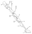
ジョイントコネクタCO内には、図2に示すジョイント端子5が一対収容されている(図1では一方のジョイント端子5のみが示されている。)。ジョイント端子5は導電金属製であり、幅方向に並列する3本のタブ端子6とこれらタブ端子6の端部を連結する平板状の連結片7とから形成されている。上記したツイストペア線でペアをなす電線Wは、両ジョイント端子5間でペアとなるタブ端子6にペアしそれぞれ雌端子9A,9Bを介して接続される。
雌端子9A,9Bは、幹線用と分岐線用のそれぞれに関して同一のものが使用されている。雌端子9A,9Bも導電金属製の板材をプレスにて打ち抜いた後に、所定形状に曲げ加工したものである。雌端子9A,9Bは、タブ端子6が差し込み可能な角筒状の端子接続部10と、その後部に配された電線接続部11とからなっている。電線接続部11は、さらに電線(ツイストペア線を構成する各電線)の端部に露出する芯線をかしめ付けるワイヤバレル11Aと、電線Wの被覆部分をかしめ付けるインシュレーションバレル11Bとからなっている。
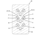
ハウジング15は合成樹脂製であり、内部には一対のジョイント端子5を収容するための一対の第1端子収容部16(図4ではハウジング15内の左側に位置する収容部であり、同図では片側の第1端子収容部16のみが示されている。)と、計3対の雌端子(2対の幹線用雌端子9Aと1対の分岐線用雌端子9B)を収容するための1対の第2端子収容部17とが形成されている(図4ではハウジング内の右側に位置する収容部であり、同図では片側の第2端子収容部17のみが示されている。)。各第2端子収容部17は二つの幹線用雌端子9Aと一つの分岐線用雌端子9Bとを収容するキャビティ18を計3室ずつ備えている。
また、ハウジング15において、後述するリテーナ装着孔22の本体部収容部22A(図5参照)の前側にはツイストペア線の各電線Wに接続された雌端子9A,9Bのペアを同時に係止するようにしたランス13が設けられている。これらランス13は、第2端子収容部17においてX方向に関し3つが配されている。各ランス13は、図17〜図19に示すように、前方へ向けて片持ち状に延出して形成されている。さらに、各ランス13はY方向に隣接するキャビティ18間に跨る幅を有して形成され、かつそれぞれはX方向に沿って撓み変形可能であり、Y方向に隣接する両キャビティ18に収容される雌端子9A,9Bのペアを一括して係止できるように一体に形成されている。
図1に示すように、幹線1は各電子制御ユニットUへの分岐ポイント3毎に、迂回経路4を有している。各迂回経路4は、ジョイントコネクタCOに向かう往路4Aと、ジョイントコネクタCOから再び幹線1へと回帰する復路4Bとからなっている。往路4Aとなるツイストペア線を構成する両電線Wの端部、及び復路4Bとなるツイストペア線を構成する両電線Wの端部に対しそれぞれ幹線用雌端子9Aを接続しておく。また、各電子制御ユニットUに接続される分岐線となるツイストペア線を構成する両電線Wの端部に対しそれぞれ分岐線用雌端子9Bを接続しておく。
本発明は上記記述及び図面によって説明した実施例に限定されるものではなく、例えば次のような実施例も本発明の技術的範囲に含まれる。
(1)上記実施例では、車載ネットワークに使用されるジョイントコネクタに適用した場合を示したが、本発明においては、コネクタの用途・形式は限定されるべきものではない。例えば、上記実施例では一つのハウジング内にジョイント端子と雌端子を同時に収容する場合を示したが、雌端子のみを収容する雌コネクタに適用してもよい。
(3)上記実施例では、共用解除操作部をランスにおける前端部の幅方向中央部に配置した場合を示したが、例えば幅方向の少なくともいずれか一方の端部に配置するようにしてもよい。要は、共用解除操作部を解除操作したときに、ランスがねじれ等を生じることなく、幅方向でバランスして解除方向へ撓み変形させうる位置であれば設置個所は限定されるべきものではない。
9B…分岐線用雌端子(端子)
13…ランス
15…ハウジング
18…キャビティ
30…共用用解除操作部
W…電線
CO…ジョイントコネクタ(コネクタ)
Claims (4)
- 一対の電線を撚り合せてなるツイストペア線と、
前記ツイストペア線の各端末にそれぞれ接続された一対の端子と、
前記一対の端子を個別に収容するキャビティが形成されたハウジングと、
前記ハウジング内に撓み可能に配されて前記一対の端子にそれぞれ一箇所だけ形成された係止部位に係止可能なランスとを備えたコネクタであって、
前記ツイストペア線に接続された前記端子のペアは隣接する前記キャビティ内に収容されるともに、前記隣接するキャビティ内にはこれらキャビティ間に跨るようにして、前記ランスが一体にかつ連動可能に形成されていることを特徴とするコネクタ。 - 前記ランスの前部には、前記端子との係止解除を行うための共用解除操作部が形成されていることを特徴とする請求項1に記載のコネクタ。
- 前記ハウジングの側面には前記ランスの両側面部を成形するための抜き孔が対をなして開口するとともに、前記抜き孔は前記端子と係止するリテーナを装着するためのリテーナ装着孔に連通し、前記リテーナが前記ハウジングに装着された状態で前記リテーナにて前記抜き孔の開口が閉止されることを特徴とする請求項1又は2に記載のコネクタ。
- 前記ツイストペア線に接続されたペアとなる前記端子を収容するキャビティの並び方向が、前記ランスの撓み方向と直交する方向に設定されていることを特徴とする請求項1乃至請求項3のいずれか一項に記載のコネクタ。
Priority Applications (5)
| Application Number | Priority Date | Filing Date | Title |
|---|---|---|---|
| JP2015003833A JP6315345B2 (ja) | 2015-01-13 | 2015-01-13 | コネクタ |
| DE112016000324.2T DE112016000324T5 (de) | 2015-01-13 | 2016-01-05 | Verbinder |
| CN201680005430.XA CN107210556B (zh) | 2015-01-13 | 2016-01-05 | 连接器 |
| PCT/JP2016/050171 WO2016114179A1 (ja) | 2015-01-13 | 2016-01-05 | コネクタ |
| US15/537,999 US10079445B2 (en) | 2015-01-13 | 2016-01-05 | Electrical connector for a twisted pair cable |
Applications Claiming Priority (1)
| Application Number | Priority Date | Filing Date | Title |
|---|---|---|---|
| JP2015003833A JP6315345B2 (ja) | 2015-01-13 | 2015-01-13 | コネクタ |
Publications (3)
| Publication Number | Publication Date |
|---|---|
| JP2016131064A JP2016131064A (ja) | 2016-07-21 |
| JP2016131064A5 JP2016131064A5 (ja) | 2017-08-03 |
| JP6315345B2 true JP6315345B2 (ja) | 2018-04-25 |
Family
ID=56405726
Family Applications (1)
| Application Number | Title | Priority Date | Filing Date |
|---|---|---|---|
| JP2015003833A Active JP6315345B2 (ja) | 2015-01-13 | 2015-01-13 | コネクタ |
Country Status (5)
| Country | Link |
|---|---|
| US (1) | US10079445B2 (ja) |
| JP (1) | JP6315345B2 (ja) |
| CN (1) | CN107210556B (ja) |
| DE (1) | DE112016000324T5 (ja) |
| WO (1) | WO2016114179A1 (ja) |
Families Citing this family (3)
| Publication number | Priority date | Publication date | Assignee | Title |
|---|---|---|---|---|
| JP2020161323A (ja) * | 2019-03-26 | 2020-10-01 | 矢崎総業株式会社 | コネクタハウジング |
| JP7474959B2 (ja) * | 2019-06-11 | 2024-04-26 | パナソニックIpマネジメント株式会社 | 電子部品の接続構造 |
| JP7424247B2 (ja) * | 2020-08-26 | 2024-01-30 | 住友電装株式会社 | コネクタ |
Family Cites Families (9)
| Publication number | Priority date | Publication date | Assignee | Title |
|---|---|---|---|---|
| JPH0495369A (ja) * | 1990-08-01 | 1992-03-27 | Yazaki Corp | 端子係止具付電気コネクタ |
| JP2001184954A (ja) | 1999-12-24 | 2001-07-06 | Sumitomo Wiring Syst Ltd | ツイストペア電線の配索構造 |
| JP2001326011A (ja) * | 2000-05-19 | 2001-11-22 | Sumitomo Wiring Syst Ltd | コネクタ及び端子金具 |
| DE102004034396B4 (de) * | 2003-07-17 | 2011-12-22 | Autonetworks Technologies, Ltd. | Verbindungsteil und Verbindungsstecker für einen Kabelbaum |
| JP5272934B2 (ja) * | 2009-07-08 | 2013-08-28 | 住友電装株式会社 | コネクタ |
| JP2013069509A (ja) * | 2011-09-21 | 2013-04-18 | Auto Network Gijutsu Kenkyusho:Kk | ハーネス |
| DE102012015581A1 (de) * | 2012-08-07 | 2014-02-13 | Rosenberger Hochfrequenztechnik Gmbh & Co. Kg | Steckverbinder |
| JP2014082009A (ja) * | 2012-10-12 | 2014-05-08 | Sumitomo Wiring Syst Ltd | アース接続装置 |
| JP6206392B2 (ja) * | 2014-12-25 | 2017-10-04 | 株式会社オートネットワーク技術研究所 | ジョイントコネクタ |
-
2015
- 2015-01-13 JP JP2015003833A patent/JP6315345B2/ja active Active
-
2016
- 2016-01-05 CN CN201680005430.XA patent/CN107210556B/zh not_active Expired - Fee Related
- 2016-01-05 US US15/537,999 patent/US10079445B2/en not_active Expired - Fee Related
- 2016-01-05 DE DE112016000324.2T patent/DE112016000324T5/de not_active Withdrawn
- 2016-01-05 WO PCT/JP2016/050171 patent/WO2016114179A1/ja not_active Ceased
Also Published As
| Publication number | Publication date |
|---|---|
| US10079445B2 (en) | 2018-09-18 |
| CN107210556A (zh) | 2017-09-26 |
| WO2016114179A1 (ja) | 2016-07-21 |
| CN107210556A8 (zh) | 2018-01-09 |
| DE112016000324T5 (de) | 2017-10-19 |
| US20170352975A1 (en) | 2017-12-07 |
| CN107210556B (zh) | 2019-11-15 |
| JP2016131064A (ja) | 2016-07-21 |
Similar Documents
| Publication | Publication Date | Title |
|---|---|---|
| US11018450B2 (en) | Connector position assurance device, connector system and method for operating the connector system | |
| JP6206392B2 (ja) | ジョイントコネクタ | |
| US7556539B2 (en) | Connector | |
| US7204725B2 (en) | Connector and method of assembling it | |
| CN101728687B (zh) | 电连接器 | |
| JP2015060628A (ja) | コネクタ | |
| CN104541412A (zh) | 连接器 | |
| CN106797085B (zh) | 连接器 | |
| EP2608325A1 (en) | Waterproof connector | |
| JP2016001579A (ja) | 導電端子 | |
| CN106716729A (zh) | 连接器 | |
| JP6315345B2 (ja) | コネクタ | |
| US9153909B2 (en) | Lever-type connector | |
| US10033129B2 (en) | Connector | |
| US20150111444A1 (en) | Joint terminal | |
| CN117321860A (zh) | 连接器 | |
| JP6241754B2 (ja) | ジョイントコネクタの製造方法 | |
| JP2010129358A (ja) | コネクタ及び雌端子金具 | |
| JP6853634B2 (ja) | ロック解除機構、及び、このロック解除機構を用いた電気コネクタ組立体及びコネクタ | |
| US9196993B2 (en) | Connector unit | |
| JP7307006B2 (ja) | シールド電気コネクタ | |
| JP2008204720A (ja) | 短絡部材、短絡部材付電線、ジョイントコネクタおよび短絡方法 | |
| JP2002175851A (ja) | コネクタ | |
| JP4983759B2 (ja) | ジョイントコネクタ | |
| JP2005327503A (ja) | コネクタ |
Legal Events
| Date | Code | Title | Description |
|---|---|---|---|
| A621 | Written request for application examination |
Free format text: JAPANESE INTERMEDIATE CODE: A621 Effective date: 20170531 |
|
| A521 | Written amendment |
Free format text: JAPANESE INTERMEDIATE CODE: A523 Effective date: 20170621 |
|
| A131 | Notification of reasons for refusal |
Free format text: JAPANESE INTERMEDIATE CODE: A131 Effective date: 20171208 |
|
| A521 | Written amendment |
Free format text: JAPANESE INTERMEDIATE CODE: A523 Effective date: 20180115 |
|
| TRDD | Decision of grant or rejection written | ||
| A01 | Written decision to grant a patent or to grant a registration (utility model) |
Free format text: JAPANESE INTERMEDIATE CODE: A01 Effective date: 20180302 |
|
| A61 | First payment of annual fees (during grant procedure) |
Free format text: JAPANESE INTERMEDIATE CODE: A61 Effective date: 20180315 |
|
| R150 | Certificate of patent or registration of utility model |
Ref document number: 6315345 Country of ref document: JP Free format text: JAPANESE INTERMEDIATE CODE: R150 |