JP6315345B2 - connector - Google Patents
connector Download PDFInfo
- Publication number
- JP6315345B2 JP6315345B2 JP2015003833A JP2015003833A JP6315345B2 JP 6315345 B2 JP6315345 B2 JP 6315345B2 JP 2015003833 A JP2015003833 A JP 2015003833A JP 2015003833 A JP2015003833 A JP 2015003833A JP 6315345 B2 JP6315345 B2 JP 6315345B2
- Authority
- JP
- Japan
- Prior art keywords
- terminal
- pair
- lance
- terminals
- housing
- Prior art date
- Legal status (The legal status is an assumption and is not a legal conclusion. Google has not performed a legal analysis and makes no representation as to the accuracy of the status listed.)
- Active
Links
Images


Classifications
-
- H—ELECTRICITY
- H01—ELECTRIC ELEMENTS
- H01R—ELECTRICALLY-CONDUCTIVE CONNECTIONS; STRUCTURAL ASSOCIATIONS OF A PLURALITY OF MUTUALLY-INSULATED ELECTRICAL CONNECTING ELEMENTS; COUPLING DEVICES; CURRENT COLLECTORS
- H01R13/00—Details of coupling devices of the kinds covered by groups H01R12/70 or H01R24/00 - H01R33/00
- H01R13/40—Securing contact members in or to a base or case; Insulating of contact members
- H01R13/42—Securing in a demountable manner
- H01R13/426—Securing by a separate resilient retaining piece supported by base or case, e.g. collar or metal contact-retention clip
-
- H—ELECTRICITY
- H01—ELECTRIC ELEMENTS
- H01R—ELECTRICALLY-CONDUCTIVE CONNECTIONS; STRUCTURAL ASSOCIATIONS OF A PLURALITY OF MUTUALLY-INSULATED ELECTRICAL CONNECTING ELEMENTS; COUPLING DEVICES; CURRENT COLLECTORS
- H01R11/00—Individual connecting elements providing two or more spaced connecting locations for conductive members which are, or may be, thereby interconnected, e.g. end pieces for wires or cables supported by the wire or cable and having means for facilitating electrical connection to some other wire, terminal, or conductive member, blocks of binding posts
-
- H—ELECTRICITY
- H01—ELECTRIC ELEMENTS
- H01R—ELECTRICALLY-CONDUCTIVE CONNECTIONS; STRUCTURAL ASSOCIATIONS OF A PLURALITY OF MUTUALLY-INSULATED ELECTRICAL CONNECTING ELEMENTS; COUPLING DEVICES; CURRENT COLLECTORS
- H01R13/00—Details of coupling devices of the kinds covered by groups H01R12/70 or H01R24/00 - H01R33/00
- H01R13/40—Securing contact members in or to a base or case; Insulating of contact members
- H01R13/42—Securing in a demountable manner
- H01R13/422—Securing in resilient one-piece base or case, e.g. by friction; One-piece base or case formed with resilient locking means
- H01R13/4223—Securing in resilient one-piece base or case, e.g. by friction; One-piece base or case formed with resilient locking means comprising integral flexible contact retaining fingers
- H01R13/4226—Securing in resilient one-piece base or case, e.g. by friction; One-piece base or case formed with resilient locking means comprising integral flexible contact retaining fingers comprising two or more integral flexible retaining fingers acting on a single contact
-
- H—ELECTRICITY
- H01—ELECTRIC ELEMENTS
- H01R—ELECTRICALLY-CONDUCTIVE CONNECTIONS; STRUCTURAL ASSOCIATIONS OF A PLURALITY OF MUTUALLY-INSULATED ELECTRICAL CONNECTING ELEMENTS; COUPLING DEVICES; CURRENT COLLECTORS
- H01R13/00—Details of coupling devices of the kinds covered by groups H01R12/70 or H01R24/00 - H01R33/00
- H01R13/40—Securing contact members in or to a base or case; Insulating of contact members
- H01R13/42—Securing in a demountable manner
- H01R13/428—Securing in a demountable manner by resilient locking means on the contact members; by locking means on resilient contact members
- H01R13/434—Securing in a demountable manner by resilient locking means on the contact members; by locking means on resilient contact members by separate resilient locking means on contact member, e.g. retainer collar or ring around contact member
-
- H—ELECTRICITY
- H01—ELECTRIC ELEMENTS
- H01R—ELECTRICALLY-CONDUCTIVE CONNECTIONS; STRUCTURAL ASSOCIATIONS OF A PLURALITY OF MUTUALLY-INSULATED ELECTRICAL CONNECTING ELEMENTS; COUPLING DEVICES; CURRENT COLLECTORS
- H01R13/00—Details of coupling devices of the kinds covered by groups H01R12/70 or H01R24/00 - H01R33/00
- H01R13/40—Securing contact members in or to a base or case; Insulating of contact members
- H01R13/42—Securing in a demountable manner
- H01R13/436—Securing a plurality of contact members by one locking piece or operation
- H01R13/4361—Insertion of locking piece perpendicular to direction of contact insertion
- H01R13/4362—Insertion of locking piece perpendicular to direction of contact insertion comprising a temporary and a final locking position
-
- H—ELECTRICITY
- H01—ELECTRIC ELEMENTS
- H01R—ELECTRICALLY-CONDUCTIVE CONNECTIONS; STRUCTURAL ASSOCIATIONS OF A PLURALITY OF MUTUALLY-INSULATED ELECTRICAL CONNECTING ELEMENTS; COUPLING DEVICES; CURRENT COLLECTORS
- H01R25/00—Coupling parts adapted for simultaneous co-operation with two or more identical counterparts, e.g. for distributing energy to two or more circuits
- H01R25/003—Coupling parts adapted for simultaneous co-operation with two or more identical counterparts, e.g. for distributing energy to two or more circuits the coupling part being secured only to wires or cables
Description
本発明はコネクタに関するものであり、特に、ツイストペア電線が接続されるコネクタに関する。 The present invention relates to a connector, and more particularly to a connector to which a twisted pair electric wire is connected.
従来より、ノイズの影響からの遮蔽が要求される回路においては、ツイストペア線と呼ばれる2本の電線を撚り合せた電線が用いられることがある。このようなツイストペア線の各電線の端末にはそれぞれ端子が接続され、コネクタのハウジングに対して隣接するキャビティに収容されるようになっている。そのような技術を開示するものとして、下記特許文献1を挙げることができる。 Conventionally, in a circuit that is required to be shielded from the influence of noise, an electric wire obtained by twisting two electric wires called a twisted pair wire may be used. Terminals are connected to the ends of the respective wires of the twisted pair wires, and are accommodated in cavities adjacent to the connector housing. The following patent document 1 can be given as an example of disclosing such a technique.
上記のコネクタにおいても、通常のコネクタと同様、各端子が対応するキャビティ内に正規に収容されれば、各端子はキャビティ内にそれぞれ別個に設けられたランスによって係止され、抜け止めがなされる。しかし、近年、端子は小型化の要求が高く、それに伴ってランスも小型化しているため、端子保持力を如何にし維持するかが問題となっている。 Also in the above connector, as in the case of a normal connector, if each terminal is properly accommodated in the corresponding cavity, each terminal is locked by a lance separately provided in the cavity, and is prevented from coming off. . However, in recent years, there is a high demand for miniaturization of terminals, and the lances are also miniaturized accordingly.
一方、ツイストペア線においても、各電線に接続された端子対が正規にキャビティ内に抜け止め状態で収容されたか否かの検査がなされる。具体的には、ツイストペア線を構成する各電線に対して個別に引き抜き力を加えて検査を行うのである。しかし、ツイストペア線の場合、両電線が接近しているため、作業者は個々の電線を個別に引き抜こうとしても、両電線を摘んで同時に引き抜きがちである。そのような場合に、仮に一方の電線に接続された端子が半挿入状態であったとしても、他方の端子が正規の係止状態であると、いずれの端子も抜き取られてこない、という事態が生じてしまう。 On the other hand, also in the twisted pair wire, it is inspected whether or not the terminal pair connected to each electric wire is properly accommodated in the cavity in a state of being prevented from coming off. Specifically, an inspection is performed by individually applying a pulling force to each electric wire constituting the twisted pair wire. However, in the case of a twisted pair wire, since both wires are close to each other, even if an operator tries to pull out each wire individually, the operator tends to pick both wires and pull them out at the same time. In such a case, even if the terminal connected to one of the wires is in a half-inserted state, if the other terminal is in a regular locking state, none of the terminals are pulled out. It will occur.
従来、このことの対応として、各電線はキャビティへの入口の手前部分で、ある程度の長さ範囲に亘って撚りを解いておくようなことがなされてきた。このため、撚りが解かれた範囲ではツイストペア線のノイズ低減の機能が損なわれてしまう、との懸念があった。 Conventionally, as a countermeasure for this, each electric wire has been untwisted over a certain length range at a portion before the entrance to the cavity. For this reason, there was a concern that the function of reducing the noise of the twisted pair wire would be impaired in the untwisted range.
本発明は上記のような事情に基づいて完成されたものであって、ツイストペア線にノイズ低減機能を保持し、かつ充分な端子保持力を得ることができるコネクタを提供することを目的とする。 The present invention has been completed based on the above circumstances, and an object of the present invention is to provide a connector capable of retaining a noise reduction function in a twisted pair wire and obtaining a sufficient terminal holding force.
本発明のコネクタは、一対の電線を撚り合せてなるツイストペア線と、ツイストペア線の各端末にそれぞれ接続された一対の端子と、前記一対の端子を個別に収容するキャビティが形成されたハウジングと、ハウジング内に撓み可能に配されて前記一対の端子にそれぞれ一箇所だけ形成された係止部位にそれぞれ一箇所だけ形成された係止部位に係止可能なランスとを備えたコネクタであって、ツイストペア線に接続された端子のペアは隣接するキャビティ内に収容されるともに、隣接するキャビティ内にはこれらキャビティ間に跨るようにして、ランスが一体にかつ連動可能に形成されていることを特徴とする。 The connector of the present invention is a twisted pair wire formed by twisting a pair of electric wires, a pair of terminals connected to each terminal of the twisted pair wire, a housing in which a cavity for individually accommodating the pair of terminals is formed, A connector provided with a lance capable of being locked at a locking portion formed at a single location on a locking portion formed at a single location on each of the pair of terminals and arranged so as to be deflectable within the housing, The pair of terminals connected to the twisted pair wires are accommodated in adjacent cavities, and the lances are formed integrally and interlocked in the adjacent cavities so as to straddle between the cavities. And
本発明のコネクタにおいて、ツイストペア電線の各端末に接続された端子のペアは、対応するキャビティのペアに同時に挿入される。すると、端子のペアは一体形成されたランスを撓ませつつ前進し、各端子がキャビティ内に正規に挿入されれば、端子のペアはランスによってほぼ同時に弾性的に係止される。このように、雌端子対に対してランスが共用して形成されるよう、ランスを幅方向に大型化することができ、これによってランス自体の剛性が高められ、端子に対する保持力を向上させることができる。 In the connector of the present invention, a pair of terminals connected to each end of a twisted pair electric wire is simultaneously inserted into a corresponding pair of cavities. Then, the pair of terminals advances while bending the integrally formed lance, and if each terminal is properly inserted into the cavity, the pair of terminals is elastically locked by the lance almost simultaneously. In this way, the lance can be enlarged in the width direction so that the lance is formed in common with the female terminal pair, thereby increasing the rigidity of the lance itself and improving the holding force on the terminal. Can do.
また、端子の挿入後にはツイストペア線に対して引き抜き力が付加され、両端子が正規にランスに係止されているか否かの検査がなされる。本発明であれば、仮に、端子のペアのうちいずれか一方が半挿入であれば、ランスは撓み状態となっているため、端子のペアは揃ってキャビティから抜き取られるため、端子のペアの少なくともいずれか一方が不完全な挿入状態であったことが検知される。 Further, after the terminals are inserted, a pulling force is applied to the twisted pair wires to check whether or not both terminals are properly locked to the lance. In the present invention, if one of the pair of terminals is half inserted, the lance is in a bent state, so the pair of terminals are aligned and removed from the cavity, so that at least one of the pair of terminals It is detected that either one has been incompletely inserted.
また、本発明によれば、ツイストペア線を構成する両電線を揃って引き抜くようにしているため、従来のように、長い範囲に亘って撚りを解いておく必要がないから、ノイズ低減の機能もそのまま維持される。 In addition, according to the present invention, since both the wires constituting the twisted pair wire are pulled out together, it is not necessary to untwist over a long range as in the prior art, so the function of noise reduction is also provided. It is maintained as it is.
本発明における好ましい実施の形態を説明する。
本発明のコネクタは、前記ランスの前部には、前記端子との係止解除を行うための共用解除操作部が形成されるようにしてもよい。
このような構成によれば、共用解除操作部を操作してランスを係止解除方向に撓み変形させれば、ツイストペア線に接続された端子のペアを同時に抜き取ることができる。
A preferred embodiment of the present invention will be described.
In the connector according to the present invention, a common release operation portion for releasing the engagement with the terminal may be formed at the front portion of the lance.
According to such a configuration, by operating the common release operation portion to bend and deform the lance in the locking release direction, a pair of terminals connected to the twisted pair wire can be extracted at the same time.
<実施例>
次に、本発明のコネクタを具体化した実施例について、図面を参照しつつ説明する。
<Example>
Next, an embodiment embodying the connector of the present invention will be described with reference to the drawings.
(車載ネットワークの概要)
本実施例では、車載ネットワーク中に使用されたジョイントコネクタを例にとって説明する。
図1は、CAN(Control Area Network)と呼ばれる車載ネットワークの一部を示すものであり、複数の電子制御ユニットU同士がワイヤハーネスWHを介して通信が可能になっている。
(Outline of in-vehicle network)
In the present embodiment, a description will be given taking a joint connector used in an in-vehicle network as an example.
FIG. 1 shows a part of an in-vehicle network called CAN (Control Area Network), and a plurality of electronic control units U can communicate with each other via a wire harness WH.
ワイヤハーネスWHは、幹線1と、この幹線1から複数の分岐ポイント3において分岐し、それぞれの分岐先で各電子制御ユニットUに接続される分岐線2とから構成されている。また、幹線1及び各分岐線2は二本の電線Wを対で撚り合せたツイストペア線によって構成されている。 The wire harness WH includes a trunk line 1 and branch lines 2 that branch from the trunk line 1 at a plurality of branch points 3 and are connected to the respective electronic control units U at respective branch destinations. Moreover, the trunk line 1 and each branch line 2 are comprised by the twisted pair wire which twisted the two electric wires W in a pair.
幹線1は、各分岐ポイント3においてジョイントコネクタCOへ向けて迂回経路4が形成されている。各迂回経路4における往路4Aと復路4Bとは、ジョイントコネクタCO内において中継され、かつ各電子制御ユニットUへの分岐がなされている。 In the trunk line 1, a detour path 4 is formed at each branch point 3 toward the joint connector CO. The forward path 4A and the return path 4B in each detour path 4 are relayed in the joint connector CO and branched to each electronic control unit U.
(ジョイント端子:図2参照)
ジョイントコネクタCO内には、図2に示すジョイント端子5が一対収容されている(図1では一方のジョイント端子5のみが示されている。)。ジョイント端子5は導電金属製であり、幅方向に並列する3本のタブ端子6とこれらタブ端子6の端部を連結する平板状の連結片7とから形成されている。上記したツイストペア線でペアをなす電線Wは、両ジョイント端子5間でペアとなるタブ端子6にペアしそれぞれ雌端子9A,9Bを介して接続される。
(Joint terminal: see Fig. 2)
A pair of
各タブ端子6の長さ方向の中央部における一方の側縁には略方形状のフォロア部8が張り出し形成されている。各フォロア部8の前縁部には表面が湾曲状をなす面取り部8Aが形成されている。面取り部8Aは、後述するカム部27への進入を円滑にするためのものである。
A substantially
ジョイント端子5は、平板の母材からプレスによって打ち抜いて形成したものであり、したがって、タブ端子6の両側縁は破断面となっている。タブ端子6はプレスによって打ち抜かれたときの形態は、図2に示すように、各タブ端子6の板面(同図に示す表面と裏面)と連結片7の板面とは同一平面をなす形態であるが、ジョイントコネクタCOに組込まれた後の形態は、図3に示すように、各タブ端子6がその軸線周りに90度捻られて、連結片7の板面とタブ端子6の板面とが略直交した位置関係となっている。このことについては、後に詳述する。
The
(雌端子:図3参照)
雌端子9A,9Bは、幹線用と分岐線用のそれぞれに関して同一のものが使用されている。雌端子9A,9Bも導電金属製の板材をプレスにて打ち抜いた後に、所定形状に曲げ加工したものである。雌端子9A,9Bは、タブ端子6が差し込み可能な角筒状の端子接続部10と、その後部に配された電線接続部11とからなっている。電線接続部11は、さらに電線(ツイストペア線を構成する各電線)の端部に露出する芯線をかしめ付けるワイヤバレル11Aと、電線Wの被覆部分をかしめ付けるインシュレーションバレル11Bとからなっている。
(Female terminal: see Fig. 3)
The same
端子接続部10は角筒状に折り曲げられて形成され、天井面は二重壁となっている。端子接続部10の天井面のうち外面側は、長手方向の中央部において切り欠かれ、一重の構造となっている。端子接続部10における天井面の外面側はこの切欠き部分を前後に挟んで、一対の突部12A,12Bが突出形成されている。両突部12A,12Bは共にスタビライザとしての機能を有し、前側の突部12Aは後述するランス13と係止する機能も有している。
The terminal connecting
また、図4等に示すように、端子接続部10の内部にはジョイント端子5の各タブ端子6と電気的な接続を行うための弾性接触片14が形成されている。同図に示すように、弾性接触片14は後方へ片持ち状に延出して形成され、両突部12A,12Bの突出する方向とは反対方向への撓みが可能である。換言すれば、弾性接触片14の撓みはランス13の撓み方向(X方向:図4、図6参照)に沿って行なわれるようになっている。
Moreover, as shown in FIG. 4 etc., the
(コネクタのハウジング:主として図4〜図8参照)
ハウジング15は合成樹脂製であり、内部には一対のジョイント端子5を収容するための一対の第1端子収容部16(図4ではハウジング15内の左側に位置する収容部であり、同図では片側の第1端子収容部16のみが示されている。)と、計3対の雌端子(2対の幹線用雌端子9Aと1対の分岐線用雌端子9B)を収容するための1対の第2端子収容部17とが形成されている(図4ではハウジング内の右側に位置する収容部であり、同図では片側の第2端子収容部17のみが示されている。)。各第2端子収容部17は二つの幹線用雌端子9Aと一つの分岐線用雌端子9Bとを収容するキャビティ18を計3室ずつ備えている。
(Connector housing: Refer mainly to FIGS. 4 to 8)
The
図6に示すように、ツイストペア線を構成する両電線Wに接続されたペアとなる雌端子(幹線用雌端子9A及び分岐線用雌端子9B)は、ペアをなす各第2端子収容部17において、図示左右方向(同図ではY方向)で隣接するキャビティ18内に収容される。同図に示されるように、各第2端子収容部17を構成するキャビティ18において、Y方向に関するピッチはX方向に関するピッチよりも狭くなるように設定されている。
As shown in FIG. 6, the female terminals (the main terminal female terminal 9 </ b> A and the branch line female terminal 9 </ b> B) connected to the both wires W constituting the twisted pair wire are paired with each second
また、図4等に示すように、各第2端子収容部17と対応する両第1端子収容部16との境界壁19にはタブ端子6を貫通させるための挿通孔20が開口するとともに、ランス13の前端中央部の共用解除操作部30を成形あるいはランス13の係止解除操作を行うための通し孔21が開口している。この通し孔21は、ハウジング15内を前後方向に沿って第1端子収容部16側へ連通するようにして形成されている。
Further, as shown in FIG. 4 and the like, an
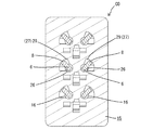
(ランス:主として図17〜図19参照)
また、ハウジング15において、後述するリテーナ装着孔22の本体部収容部22A(図5参照)の前側にはツイストペア線の各電線Wに接続された雌端子9A,9Bのペアを同時に係止するようにしたランス13が設けられている。これらランス13は、第2端子収容部17においてX方向に関し3つが配されている。各ランス13は、図17〜図19に示すように、前方へ向けて片持ち状に延出して形成されている。さらに、各ランス13はY方向に隣接するキャビティ18間に跨る幅を有して形成され、かつそれぞれはX方向に沿って撓み変形可能であり、Y方向に隣接する両キャビティ18に収容される雌端子9A,9Bのペアを一括して係止できるように一体に形成されている。
(Lance: Refer mainly to FIGS. 17 to 19)
Further, in the
図19に示すように、ランス13の上面のうち両雌端子9A,9Bの前側の突部12Aが通過する領域には、一対の逃がし凹部31が凹み形成されている。両逃がし凹部31は、ランス13の後端から前端よりやや後方の部位に至るまでの範囲に亘って前後方向に沿って形成されている。両逃がし凹部31における後端から中央部までの間は略水平状に形成され、雌端子9A,9Bがランスに係止されている状態では、後側の突部12Bが位置する水平凹部31Aが形成されているが、中央部から前端に至るまでは徐々に上り勾配の斜面31Bが形成されている。ランスの前端面の中央部は奥方へ向けて切欠かれ、奥面には前記した共用解除操作部30が形成されている。
As shown in FIG. 19, a pair of
ランス13の前端面には前記した共用解除操作部30を幅方向に挟んで一対の係止面32が形成され、それぞれは対応する雌端子9A,9Bの前側の突部12Aと係止可能である。雌端子9A,9Bのペアに対する係止を解除する際には、通し孔21に対し第1端子収容部16側から長い棒状の解除治具(図示しない)が差し込まれて共用解除操作部30を操作することによって、ランス13が解除方向へ撓み操作される。
A pair of locking
図18に示すように、各ランス13はY方向に隣接する両キャビティ18に対し図示左方向に僅かに偏位するようにして形成されている。そして、同図に示すように、両キャビティ18間の仕切り壁33と共用解除操作部30とが幅方向に関して対応するような位置関係となっている。また、両係止面32のうち図18に示す右側に位置するものは、対応するキャビティ18と幅方向に関して整合する位置関係にあり、かつ同キャビティ18に対しやや狭めの幅寸法にて形成されているが、両係止面32のうち左側に位置するものは、対応するキャビティ18に対しやや左方に偏位した位置関係にあり、かつ、同キャビティ18とほぼ同幅の寸法をもって形成されている。
As shown in FIG. 18, each
また、図17、図18に示すように、各ランス13の幅方向の両側面の前部側を成形するために、ハウジング15の両側面には各ランス13毎に片側計3個ずつの抜き孔34が開口している。したがって、ハウジング15の単体状態では、各抜き孔34から各ランス13の前部側の両側面は外部へ露出されている。一方、各抜き孔34はリテーナ装着孔22の両脚部収容部22Bに連通されており、リテーナ23がハウジング15に正規に装着されると、リテーナ23の脚部が各抜き孔34を閉止して各ランス13を隠蔽することができるようになっている。
Also, as shown in FIGS. 17 and 18, in order to mold the front side of both side surfaces in the width direction of each
さらに、図5に示すように、ハウジング15における一側面にはリテーナ装着孔22が開口している。リテーナ装着孔22は全キャビティ18に連通するようにして形成されている。リテーナ装着孔22はリテーナ23の本体部23Aと整合して収容する本体部収容部22Aと、その幅方向両側に連通するようにして配されてリテーナ23の両脚部(詳細には図示しない)を収容する一対の脚部収容部22Bとから構成されている。
Further, as shown in FIG. 5, a
一方、このリテーナ装着孔22に装着されるリテーナ23の本体部23Aは、雌端子9A,9Bを挿通可能な枠状に形成され、各枠部には各雌端子9A,9Bの端子接続部10の後端にそれぞれ係止可能な係止突起24が形成されている。また、リテーナ23の両脚部は詳細には図示しないが、対応する脚部収容部22Bに対し深さ方向の二位置で係止するようにしてあり、その結果、リテーナ23はハウジング15に対して仮係止位置と本係止位置の二位置で保持されるようになっている。仮係止位置では、各係止突起24が雌端子9A,9Bの進入経路の外側に待機することで、各雌端子9A,9Bがキャビティ18に対して抜き差し自在となっているが、本係止位置では、各係止突起24が雌端子9A,9Bの進入経路内に突入することで、端子接続部10の後端に係止可能である。
On the other hand, the
次に、第1端子収容部16について説明すると、図7に示すように、第1端子収容部16はY方向に沿った二段の配置となっている。図13等に示すように、両第1端子収容部16の入口部分には両ジョイント端子5の連結片7が収容される連結片収容部25が形成されている。連結片収容部25の開口幅は、対応するジョイント端子5の連結片7の幅より僅かに狭めに形成されている。したがって、ジョイント端子5が第1端子収容部16に収容された状態では、連結片7は前端縁が第1端子収容部16の奥壁に突き当てられるとともに、連結片収容部25に対し圧入気味に嵌め入れられることで、全体の抜け止めがされている。
Next, the first
図7、図9、図10に示すように、両第1端子収容部16内にはそれぞれ3つのタブ進入路26がX方向に沿って並列して形成されており、それぞれはジョイント端子5の各タブ端子6を差し込み可能となっている。各タブ進入路26はそれぞれ前後方向に沿って真っ直ぐに形成され、それぞれはジョイント端子5の各タブ端子6を差し込み可能となっている。各タブ進入路26はそれぞれ前後方向に沿って真っ直ぐに形成され、対応するキャビティとほぼ同軸をなしている。各タブ進入路の入口部分は連結片収容部25に連通した状態で形成されている。各タブ進入路26の前端は前述した挿通孔20として境界壁19に開口している。タブ進入路26は、図7等に示すように、タブ端子の外径より大きな孔径を有する略円形の孔形状にて形成されている。
As shown in FIGS. 7, 9, and 10, in each of the first
図15〜図16に示すように、各タブ進入路26にはその全長に亘ってカム部27が連通して形成されている。カム部27はフォロア部8の板厚と略等しいか、それよりもやや大きめの厚みをもって形成されており、フォロア部8を進入させうる。図15、図16に示すように、カム部27は第1端子収容部16の入口(ハウジング15の後端)からやや奥方に入り込んだ位置に至るまでは前後方向に沿って真っ直ぐなストレート部28となっている。そして、ストレート部28より前部側の長さ範囲には螺旋部29が形成されている。螺旋部29はタブ進入路26の軸線周りに螺旋状に旋回するようにして形成されている。本実施例の場合、螺旋の始端から終端に至るまでの旋回角度は略90度である。カム部27は螺旋の終端から先も、螺旋の終端における断面形状を維持したまま前端に至るように形成されている。
As shown in FIGS. 15 to 16, each
但し、左右方向(Y方向)でペアをなす第1端子収容部16間においては、螺旋を描く旋回方向は逆向きとなっている。例えば、図10、図12、図14において、左右方向で右側に位置する第1端子収容部16では、旋回方向が時計周りであるのに対し、左右方向で左側に位置する第1端子収容部16では、反時計周りとなっている。
However, between the first
かくして、ジョイント端子5が第1端子収容部16に差し込まれていく過程で、各タブ端子6のフォロア部8は当初、カム部27のストレート部28に沿って前進するため、タブ端子6の変形は生じない。しかし、図11に示すように、フォロア部8がカム部27の螺旋部29に進入した時点では、ジョイント端子5の連結片7の前端部が連結片収容部25内に進入して板厚方向から挟持されているため、以後、フォロア部8が螺旋部29の螺旋経路に沿って移動することに伴って各タブ端子6はそれぞれの軸線周りに捻り変形させられる。この結果、フォロア部8は連結片7とは略90度位相がずれた関係となる。換言すれば、ジョイント端子5が第1端子収容部16に差し込まれる当初の時点では、タブ端子6の板面方向はY方向に沿う方向であったが、ジョイント端子5が第1端子収容部16への差込みが完了した時点では、タブ端子6の板面方向はX方向へと変換されることになる。
Thus, in the process in which the
なお、ジョイント端子5の差し込み操作が完了した状態で、フォロア部8は螺旋部29の前端部に位置し、螺旋部29の対向する内壁面によって板厚方向から挟持された状態にあるため、捻り変形の状態からの戻り(スプリングバック)を生じることがないよう規制されている。
In the state where the insertion operation of the
次に、ジョイントコネクタCOの製造手順の一例について説明する。まず、両ジョイント端子5を、第1端子収容部16内に収容する作業がなされる。その場合、両ジョイント端子5の各タブ端子6を対応するタブ進入路26へ差し込むと同時に、各フォロア部8を対応するカム部27のストレート部28へ差し込む(図9、図10参照)。
Next, an example of the manufacturing procedure of the joint connector CO will be described. First, an operation of accommodating both
そのままジョイント端子5を押し込むと、図11に示すように、連結片7の前端部が連結片収容部25の入口部分に入り込むため、連結片7は連結片収容部25内の対向壁面によって板面方向から挟持される。一方、各フォロア部8が螺旋部29の入口部分に進入するため、ジョイント端子5の押込みに伴って、フォロア部8は螺旋部29の内面(カム面)からタブ端子6の軸芯周りに所定方向への捻り力を受ける。
When the
そして、連結片7の前端が第1端子収容部16の奥壁に突き当てられると、ジョイント端子5の差込みが完了する。このときには、連結片7の長手方向両側縁が連結片収容部25内の対向壁に食い込み気味にして圧入されるため、ジョイント端子5全体が第1端子収容部16に対して抜け止め状態で収容される。一方、このときには各フォロア部8は螺旋部29の前端部に至っており、フォロア部8がここに至るまでの間に、各タブ端子6はその軸線周りに90度の捻りが加えられる。その結果、前述したように、各タブ端子6の板面は当初、連結片7の板面方向と同方向であるY方向を向いていたが、ジョイント端子5の収容完了時には90度捻られてX方向に変換されている。
Then, when the front end of the connecting
次に、ジョイント端子5の各タブに対する幹線用雌端子9Aおよび分岐線用雌端子9Bとの接続について説明する。
図1に示すように、幹線1は各電子制御ユニットUへの分岐ポイント3毎に、迂回経路4を有している。各迂回経路4は、ジョイントコネクタCOに向かう往路4Aと、ジョイントコネクタCOから再び幹線1へと回帰する復路4Bとからなっている。往路4Aとなるツイストペア線を構成する両電線Wの端部、及び復路4Bとなるツイストペア線を構成する両電線Wの端部に対しそれぞれ幹線用雌端子9Aを接続しておく。また、各電子制御ユニットUに接続される分岐線となるツイストペア線を構成する両電線Wの端部に対しそれぞれ分岐線用雌端子9Bを接続しておく。
Next, the connection of the main
As shown in FIG. 1, the trunk line 1 has a detour path 4 for each branch point 3 to each electronic control unit U. Each detour path 4 includes an outward path 4A toward the joint connector CO and a return path 4B that returns from the joint connector CO to the main line 1 again. The main
そして、図1に示すようにして、迂回経路4の往路4Aを構成するツイストペア線の各端部に接続された幹線用雌端子9Aのペアが、図6でY方向でペアとなる両第2端子収容部17の図示左端のキャビティ18(図1において、キャビティ18は図示省略)内に同時に差し込まれる(なお、図1では図面作成の便宜上、一方の幹線用雌端子9A及び一方のジョイント端子5のみが示されている)。同様にして、迂回経路4の復路4Bに接続された幹線用雌端子9Aのペアが、Y方向でペアとなる両第2端子収容部17の図示中央のキャビティ18内にそれぞれ同時に差し込まれる。また、分岐線用雌端子9Bのペアは、Y方向でペアとなる両第2端子収容部17の図示右端のキャビティ18内に同時に差し込まれる。
Then, as shown in FIG. 1, a pair of trunk
なお、いずれの雌端子のペアが対応するキャビティのペアに挿入される場合に、ツイストペア線は両キャビティ18の入口部分においても、従来のように、撚りを解かれることなく、電線相互が撚り合わされたままの接近した状態である。また、前述したように、各雌端子9A,9Bがキャビティ18内に挿入される際には、リテーナ23は仮係止位置に保持されている。
When any pair of female terminals is inserted into the corresponding pair of cavities, the twisted pair wires are twisted between the wires at the entrances of both
こうして、ツイストペア線の各電線Wに接続された雌端子9A,9BのペアがY方向で対応するキャビティ18内に同時に差し込まれると、両端子は一体となった同一のランス13を撓ませつつ前進し、前側の突部12Aがランス13を通過すると、ランス13は弾性復帰する。その結果、雌端子9A,9Bのペアはランス13に対して揃って係止し、一次係止状態となる。その後に、リテーナ23を仮係止から本係止位置に移動させると、リテーナ23の各係止突起24が対応する雌端子9A,9Bの端子接続部10の後端に係止するため、各雌端子9A,9Bはランス13と併せて二重に抜け止めがされる。
Thus, when the pair of
上記のようにして各雌端子9A,9Bが対応するキャビティ18内に正規に挿入されると、各雌端子9A,9Bの端子接続部内に対応するジョイント端子5のタブ端子6が進入される。この過程で、タブ端子6は弾性接触片14を撓ませつつ摺接して電気的な接続状態となる。この間、弾性接触片14はタブ端子6の破断面ではなく板面と接するため、破断面から損傷を受けることはない。
When the
以上のように、本実施例のジョイントコネクタCOにおいては、ツイストペア線に接続された雌端子9A,9Bのペアは、一つのランス13を共用するものであるため、一方の雌端子のみが半挿入で、他方の雌端子が正規に係止されている、といった状況はない。その点、従来であれば、個別のランスに係止するようにしていたため、ペアを構成する一方の雌端子がランス13に係止している場合には、他方の雌端子が半挿入の場合であっても、引き抜かれないという事態が想定されたが、本実施例では、そのような場合には、雌端子9A,9Bのペアは揃ってキャビティ18から引き抜かれる。したがって、従来のように、キャビティ18の入口部分においてツイストペア線の撚りを解く必要もなく、撚り合せの状態のままキャビティへ挿入することができる。したがって、電線W同士は互いの距離が接近された状態のままであるため、ノイズ低減の機能が損なわれることがない。
As described above, in the joint connector CO of the present embodiment, since the pair of
また、従来であれば、雌端子9A,9Bのペアは個別のランスに係止されるようにしていたため、端子の小型化に伴ってランスも細幅になってくると、ランス自体の剛性低下によって端子保持力が得られないことが懸念されるが、本実施例では共用のランス13によって広幅のものとなっているため、雌端子9A,9Bに対して高い保持力が得られる。
Further, conventionally, since the pair of
また、本実施例のジョイントコネクタCOは、次のような作用効果もある。すなわち、ジョイント端子5と迂回経路4における往路用及び復路用の幹線用雌端子9Aとが中継されることで、幹線1の分岐ポイント3間の接続がなされる。この要領で各分岐ポイント3間を接続することで、幹線1全体が構成される。また、各分岐ポイント3においてジョイント端子5と分岐線用雌端子9Bとが接続されることで、各電子制御ユニットUが幹線1から分岐して接続がなされる。この要領で、各分岐ポイント3で接続がなされることで車載ネットワークが構築され、電子制御ユニットU間での通信が可能となる。
Further, the joint connector CO of the present embodiment also has the following operational effects. That is, the connection between the branch points 3 of the main line 1 is made by relaying the
さらに、本実施例によれば、各ツイストペア線に接続された雌端子9A,9Bのペアを収容するキャビティの並び方向(Y方向)に、ランス13の撓み方向を設定せず、これと直交する方向(X方向)に設定している。したがって、雌端子9A,9Bのペアを収容するキャビティ間のピッチを詰めることができる。したがって、コネクタとの接続部位においても、ツイストペア線の持つ高いノイズ除去機能をキャビティ内においても保持することができる。また、このような構成を採用するにあたって、ランス13の位置を変更しても、タブ端子6を軸線周りに略90度捻るようにしたため、雌端子の弾性接触片14をジョイント端子5のタブ端子6の破断面と接することがなく、弾性接触片14を損傷から保護することができる。しかも、タブ端子6の捻り加工を事前に行っておくのではなく、ジョイントコネクタCOのハウジング15への挿入操作に伴って行うようにしたため、事前の加工がない分、ジョイントコネクタの製造効率を高めることができる。
Furthermore, according to the present embodiment, the bending direction of the
さらに、本実施例によれば、ジョイント端子5の差し込み操作が完了した状態で、フォロア部8は螺旋部29の前端部に位置し、螺旋部29の対向する内壁面によって板厚方向から挟持された状態にあるため、各タブ端子6は捻り変形の状態からの戻り(スプリングバック)を生じることがないようになっている。したがって、タブ端子6は対応する雌端子9A,9Bの弾性接触片14の板面に対して安定的に接することができる、という効果も得られる。
Furthermore, according to the present embodiment, the
<他の実施例>
本発明は上記記述及び図面によって説明した実施例に限定されるものではなく、例えば次のような実施例も本発明の技術的範囲に含まれる。
(1)上記実施例では、車載ネットワークに使用されるジョイントコネクタに適用した場合を示したが、本発明においては、コネクタの用途・形式は限定されるべきものではない。例えば、上記実施例では一つのハウジング内にジョイント端子と雌端子を同時に収容する場合を示したが、雌端子のみを収容する雌コネクタに適用してもよい。
<Other embodiments>
The present invention is not limited to the embodiments described with reference to the above description and drawings. For example, the following embodiments are also included in the technical scope of the present invention.
(1) In the above-described embodiment, the case where the present invention is applied to a joint connector used in an in-vehicle network has been described. However, in the present invention, the usage and form of the connector should not be limited. For example, although the case where the joint terminal and the female terminal are simultaneously accommodated in one housing is shown in the above embodiment, the present invention may be applied to a female connector that accommodates only the female terminal.
(2)上記実施例では、ランスは雌端子を係止する場合について示したが、雄端子を係止するものであってもよいのは勿論である。
(3)上記実施例では、共用解除操作部をランスにおける前端部の幅方向中央部に配置した場合を示したが、例えば幅方向の少なくともいずれか一方の端部に配置するようにしてもよい。要は、共用解除操作部を解除操作したときに、ランスがねじれ等を生じることなく、幅方向でバランスして解除方向へ撓み変形させうる位置であれば設置個所は限定されるべきものではない。
(2) In the above-described embodiment, the lance has been shown for locking the female terminal, but it goes without saying that the lance may lock the male terminal.
(3) In the above-described embodiment, the case where the common release operation portion is arranged at the center in the width direction of the front end portion of the lance has been described. . In short, the installation location should not be limited as long as the lance is balanced in the width direction and can be bent and deformed in the release direction without causing twisting or the like when the common release operation part is released. .
9A…幹線用雌端子(端子)
9B…分岐線用雌端子(端子)
13…ランス
15…ハウジング
18…キャビティ
30…共用用解除操作部
W…電線
CO…ジョイントコネクタ(コネクタ)
9A ... Female terminal for trunk (terminal)
9B: Branch line female terminal (terminal)
13 ...
Claims (4)
前記ツイストペア線の各端末にそれぞれ接続された一対の端子と、
前記一対の端子を個別に収容するキャビティが形成されたハウジングと、
前記ハウジング内に撓み可能に配されて前記一対の端子にそれぞれ一箇所だけ形成された係止部位に係止可能なランスとを備えたコネクタであって、
前記ツイストペア線に接続された前記端子のペアは隣接する前記キャビティ内に収容されるともに、前記隣接するキャビティ内にはこれらキャビティ間に跨るようにして、前記ランスが一体にかつ連動可能に形成されていることを特徴とするコネクタ。 A twisted pair wire formed by twisting a pair of wires;
A pair of terminals respectively connected to each terminal of the twisted pair wire;
A housing in which a cavity for individually accommodating the pair of terminals is formed;
A connector provided with a lance that is arranged in the housing so as to be able to bend and can be locked at a locking portion formed at each of the pair of terminals .
The pair of terminals connected to the twisted pair wires are accommodated in the adjacent cavities, and the lances are formed integrally and interlocked in the adjacent cavities so as to straddle the cavities. A connector characterized by that.
Priority Applications (5)
| Application Number | Priority Date | Filing Date | Title |
|---|---|---|---|
| JP2015003833A JP6315345B2 (en) | 2015-01-13 | 2015-01-13 | connector |
| US15/537,999 US10079445B2 (en) | 2015-01-13 | 2016-01-05 | Electrical connector for a twisted pair cable |
| CN201680005430.XA CN107210556B (en) | 2015-01-13 | 2016-01-05 | Connector |
| DE112016000324.2T DE112016000324T5 (en) | 2015-01-13 | 2016-01-05 | Interconnects |
| PCT/JP2016/050171 WO2016114179A1 (en) | 2015-01-13 | 2016-01-05 | Connector |
Applications Claiming Priority (1)
| Application Number | Priority Date | Filing Date | Title |
|---|---|---|---|
| JP2015003833A JP6315345B2 (en) | 2015-01-13 | 2015-01-13 | connector |
Publications (3)
| Publication Number | Publication Date |
|---|---|
| JP2016131064A JP2016131064A (en) | 2016-07-21 |
| JP2016131064A5 JP2016131064A5 (en) | 2017-08-03 |
| JP6315345B2 true JP6315345B2 (en) | 2018-04-25 |
Family
ID=56405726
Family Applications (1)
| Application Number | Title | Priority Date | Filing Date |
|---|---|---|---|
| JP2015003833A Active JP6315345B2 (en) | 2015-01-13 | 2015-01-13 | connector |
Country Status (5)
| Country | Link |
|---|---|
| US (1) | US10079445B2 (en) |
| JP (1) | JP6315345B2 (en) |
| CN (1) | CN107210556B (en) |
| DE (1) | DE112016000324T5 (en) |
| WO (1) | WO2016114179A1 (en) |
Families Citing this family (2)
| Publication number | Priority date | Publication date | Assignee | Title |
|---|---|---|---|---|
| JP2020161323A (en) * | 2019-03-26 | 2020-10-01 | 矢崎総業株式会社 | Connector housing |
| JP7424247B2 (en) * | 2020-08-26 | 2024-01-30 | 住友電装株式会社 | connector |
Family Cites Families (9)
| Publication number | Priority date | Publication date | Assignee | Title |
|---|---|---|---|---|
| JPH0495369A (en) * | 1990-08-01 | 1992-03-27 | Yazaki Corp | Electrical connector with terminal fixture |
| JP2001184954A (en) | 1999-12-24 | 2001-07-06 | Sumitomo Wiring Syst Ltd | Structure of arranging twisted pairs of electric wires |
| JP2001326011A (en) * | 2000-05-19 | 2001-11-22 | Sumitomo Wiring Syst Ltd | Connector and terminal fitting |
| DE102004034396B4 (en) * | 2003-07-17 | 2011-12-22 | Autonetworks Technologies, Ltd. | Connector and connector for a wiring harness |
| JP5272934B2 (en) * | 2009-07-08 | 2013-08-28 | 住友電装株式会社 | connector |
| JP2013069509A (en) * | 2011-09-21 | 2013-04-18 | Auto Network Gijutsu Kenkyusho:Kk | Harness |
| DE102012015581A1 (en) * | 2012-08-07 | 2014-02-13 | Rosenberger Hochfrequenztechnik Gmbh & Co. Kg | Connectors |
| JP2014082009A (en) * | 2012-10-12 | 2014-05-08 | Sumitomo Wiring Syst Ltd | Ground connection device |
| JP6206392B2 (en) * | 2014-12-25 | 2017-10-04 | 株式会社オートネットワーク技術研究所 | Joint connector |
-
2015
- 2015-01-13 JP JP2015003833A patent/JP6315345B2/en active Active
-
2016
- 2016-01-05 DE DE112016000324.2T patent/DE112016000324T5/en not_active Withdrawn
- 2016-01-05 US US15/537,999 patent/US10079445B2/en not_active Expired - Fee Related
- 2016-01-05 CN CN201680005430.XA patent/CN107210556B/en not_active Expired - Fee Related
- 2016-01-05 WO PCT/JP2016/050171 patent/WO2016114179A1/en active Application Filing
Also Published As
| Publication number | Publication date |
|---|---|
| JP2016131064A (en) | 2016-07-21 |
| US10079445B2 (en) | 2018-09-18 |
| DE112016000324T5 (en) | 2017-10-19 |
| CN107210556A8 (en) | 2018-01-09 |
| CN107210556A (en) | 2017-09-26 |
| CN107210556B (en) | 2019-11-15 |
| US20170352975A1 (en) | 2017-12-07 |
| WO2016114179A1 (en) | 2016-07-21 |
Similar Documents
| Publication | Publication Date | Title |
|---|---|---|
| US11018450B2 (en) | Connector position assurance device, connector system and method for operating the connector system | |
| JP6206392B2 (en) | Joint connector | |
| US7204725B2 (en) | Connector and method of assembling it | |
| US7556539B2 (en) | Connector | |
| JP2015060628A (en) | Connector | |
| JP2009043642A (en) | Joint connector | |
| CN104541412A (en) | Connector | |
| EP2608325A1 (en) | Waterproof connector | |
| JP2016001579A (en) | Conductive terminal | |
| JP6315345B2 (en) | connector | |
| US9153909B2 (en) | Lever-type connector | |
| US9065198B2 (en) | Connector with foreign substance entrance preventing portion | |
| US10033129B2 (en) | Connector | |
| JP6241754B2 (en) | Manufacturing method of joint connector | |
| JP6853634B2 (en) | Unlocking mechanism and electrical connector assembly and connector using this unlocking mechanism | |
| JP2010129358A (en) | Connector and female terminal fitting | |
| JP7307006B2 (en) | shielded electrical connectors | |
| US9196993B2 (en) | Connector unit | |
| JP2008204720A (en) | Short-circuiting member, wire with short-circuiting member, joint connector, and short-circuiting method | |
| JP2010009801A (en) | Connector | |
| JP2002175851A (en) | Connector | |
| JP2008198392A (en) | Joint connector | |
| JP2007533114A (en) | Electrical contact and electrical connector provided with the electrical contact | |
| JP4983759B2 (en) | Joint connector | |
| JP2008262773A (en) | Receptacle housing and receptacle connector |
Legal Events
| Date | Code | Title | Description |
|---|---|---|---|
| A621 | Written request for application examination |
Free format text: JAPANESE INTERMEDIATE CODE: A621 Effective date: 20170531 |
|
| A521 | Written amendment |
Free format text: JAPANESE INTERMEDIATE CODE: A523 Effective date: 20170621 |
|
| A131 | Notification of reasons for refusal |
Free format text: JAPANESE INTERMEDIATE CODE: A131 Effective date: 20171208 |
|
| A521 | Written amendment |
Free format text: JAPANESE INTERMEDIATE CODE: A523 Effective date: 20180115 |
|
| TRDD | Decision of grant or rejection written | ||
| A01 | Written decision to grant a patent or to grant a registration (utility model) |
Free format text: JAPANESE INTERMEDIATE CODE: A01 Effective date: 20180302 |
|
| A61 | First payment of annual fees (during grant procedure) |
Free format text: JAPANESE INTERMEDIATE CODE: A61 Effective date: 20180315 |
|
| R150 | Certificate of patent or registration of utility model |
Ref document number: 6315345 Country of ref document: JP Free format text: JAPANESE INTERMEDIATE CODE: R150 |