WO2015186495A1 - コネクタ - Google Patents
コネクタ Download PDFInfo
- Publication number
- WO2015186495A1 WO2015186495A1 PCT/JP2015/064093 JP2015064093W WO2015186495A1 WO 2015186495 A1 WO2015186495 A1 WO 2015186495A1 JP 2015064093 W JP2015064093 W JP 2015064093W WO 2015186495 A1 WO2015186495 A1 WO 2015186495A1
- Authority
- WO
- WIPO (PCT)
- Prior art keywords
- press
- connector
- protrusion
- ground member
- main
- Prior art date
Links
Images


Classifications
-
- H—ELECTRICITY
- H01—ELECTRIC ELEMENTS
- H01R—ELECTRICALLY-CONDUCTIVE CONNECTIONS; STRUCTURAL ASSOCIATIONS OF A PLURALITY OF MUTUALLY-INSULATED ELECTRICAL CONNECTING ELEMENTS; COUPLING DEVICES; CURRENT COLLECTORS
- H01R13/00—Details of coupling devices of the kinds covered by groups H01R12/70 or H01R24/00 - H01R33/00
- H01R13/46—Bases; Cases
- H01R13/502—Bases; Cases composed of different pieces
-
- H—ELECTRICITY
- H01—ELECTRIC ELEMENTS
- H01R—ELECTRICALLY-CONDUCTIVE CONNECTIONS; STRUCTURAL ASSOCIATIONS OF A PLURALITY OF MUTUALLY-INSULATED ELECTRICAL CONNECTING ELEMENTS; COUPLING DEVICES; CURRENT COLLECTORS
- H01R13/00—Details of coupling devices of the kinds covered by groups H01R12/70 or H01R24/00 - H01R33/00
- H01R13/40—Securing contact members in or to a base or case; Insulating of contact members
- H01R13/405—Securing in non-demountable manner, e.g. moulding, riveting
-
- H—ELECTRICITY
- H01—ELECTRIC ELEMENTS
- H01R—ELECTRICALLY-CONDUCTIVE CONNECTIONS; STRUCTURAL ASSOCIATIONS OF A PLURALITY OF MUTUALLY-INSULATED ELECTRICAL CONNECTING ELEMENTS; COUPLING DEVICES; CURRENT COLLECTORS
- H01R13/00—Details of coupling devices of the kinds covered by groups H01R12/70 or H01R24/00 - H01R33/00
- H01R13/40—Securing contact members in or to a base or case; Insulating of contact members
- H01R13/42—Securing in a demountable manner
-
- H—ELECTRICITY
- H01—ELECTRIC ELEMENTS
- H01R—ELECTRICALLY-CONDUCTIVE CONNECTIONS; STRUCTURAL ASSOCIATIONS OF A PLURALITY OF MUTUALLY-INSULATED ELECTRICAL CONNECTING ELEMENTS; COUPLING DEVICES; CURRENT COLLECTORS
- H01R13/00—Details of coupling devices of the kinds covered by groups H01R12/70 or H01R24/00 - H01R33/00
- H01R13/62—Means for facilitating engagement or disengagement of coupling parts or for holding them in engagement
- H01R13/639—Additional means for holding or locking coupling parts together, after engagement, e.g. separate keylock, retainer strap
-
- H—ELECTRICITY
- H01—ELECTRIC ELEMENTS
- H01R—ELECTRICALLY-CONDUCTIVE CONNECTIONS; STRUCTURAL ASSOCIATIONS OF A PLURALITY OF MUTUALLY-INSULATED ELECTRICAL CONNECTING ELEMENTS; COUPLING DEVICES; CURRENT COLLECTORS
- H01R13/00—Details of coupling devices of the kinds covered by groups H01R12/70 or H01R24/00 - H01R33/00
- H01R13/648—Protective earth or shield arrangements on coupling devices, e.g. anti-static shielding
- H01R13/652—Protective earth or shield arrangements on coupling devices, e.g. anti-static shielding with earth pin, blade or socket
-
- H—ELECTRICITY
- H01—ELECTRIC ELEMENTS
- H01R—ELECTRICALLY-CONDUCTIVE CONNECTIONS; STRUCTURAL ASSOCIATIONS OF A PLURALITY OF MUTUALLY-INSULATED ELECTRICAL CONNECTING ELEMENTS; COUPLING DEVICES; CURRENT COLLECTORS
- H01R13/00—Details of coupling devices of the kinds covered by groups H01R12/70 or H01R24/00 - H01R33/00
- H01R13/648—Protective earth or shield arrangements on coupling devices, e.g. anti-static shielding
- H01R13/658—High frequency shielding arrangements, e.g. against EMI [Electro-Magnetic Interference] or EMP [Electro-Magnetic Pulse]
- H01R13/6581—Shield structure
- H01R13/6585—Shielding material individually surrounding or interposed between mutually spaced contacts
-
- H—ELECTRICITY
- H01—ELECTRIC ELEMENTS
- H01R—ELECTRICALLY-CONDUCTIVE CONNECTIONS; STRUCTURAL ASSOCIATIONS OF A PLURALITY OF MUTUALLY-INSULATED ELECTRICAL CONNECTING ELEMENTS; COUPLING DEVICES; CURRENT COLLECTORS
- H01R24/00—Two-part coupling devices, or either of their cooperating parts, characterised by their overall structure
- H01R24/60—Contacts spaced along planar side wall transverse to longitudinal axis of engagement
-
- H—ELECTRICITY
- H01—ELECTRIC ELEMENTS
- H01R—ELECTRICALLY-CONDUCTIVE CONNECTIONS; STRUCTURAL ASSOCIATIONS OF A PLURALITY OF MUTUALLY-INSULATED ELECTRICAL CONNECTING ELEMENTS; COUPLING DEVICES; CURRENT COLLECTORS
- H01R2107/00—Four or more poles
Definitions
- the present invention relates to a connector including a ground member having a plate-like portion that is insulated from a contact and is disposed in the vicinity of the contact.
- the connector 900 of Patent Document 1 includes two contact members 910 and a ground member 920.
- Each of the contact members 910 includes a plurality of contacts 930 and an alignment member 940.
- the alignment member 940 aligns and holds the contacts 930.
- a convex portion 950 is formed on one of the two alignment members 940.
- a concave portion (not shown) corresponding to the convex portion 950 is formed in the remaining one of the two alignment members 940.
- the ground member 920 has a flat main portion 960.
- a hole 970 corresponding to the convex portion 950 is formed in the main portion 960.
- the holes 970 may be larger than the corresponding protrusions 950.
- the connector 900 of Patent Document 1 has a drawback that the ground member 920 may be loose.
- the present invention provides a connector that can attach the ground member to the alignment member without backlash even if the alignment member or the ground member has a variation in size or shape, and can appropriately position the ground member and the contact.
- the purpose is to provide.
- the connector includes a contact member and a ground member.
- the contact member includes a plurality of contacts and an alignment member.
- the alignment member aligns and holds the contacts in a pitch direction perpendicular to the front-rear direction.
- the alignment member is provided with two press-fitting protrusions and island-shaped protrusions. Each of the press-fitting protrusions protrudes in a protruding direction orthogonal to both the front-rear direction and the pitch direction.
- the island-shaped protrusions protrude in the protruding direction and extend in a predetermined direction perpendicular to the protruding direction.
- the island-shaped protrusion has a first size in the predetermined direction.
- the press-fitting protrusion has a second size in the predetermined direction.
- the first size is larger than the second size.
- the ground member has a flat main part. Two holes and a protrusion accommodating portion are formed in the main portion of the ground member. The press-fitting protrusions are press-fitted into the holes, respectively, and the island-shaped protrusions are accommodated in the protrusion accommodating portions.
- the press-fitting protrusion of the alignment member according to the present invention is press-fitted into a hole formed in the main part of the ground member.
- the press-fitting protrusion When press-fitting the press-fitting protrusion into the hole, the press-fitting protrusion may be partially cut away. Therefore, when the island-shaped protrusion is not provided on the alignment member, there is a possibility that a rotational shift occurs in the positional relationship between the ground member and the alignment member in a plane orthogonal to the protruding direction of the press-fitting protrusion. On the other hand, since the alignment member of the present invention is provided with island-like projections, the above-described rotational deviation can be prevented.
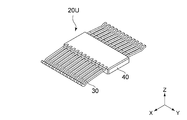
- FIG. 2 is a top perspective view showing an upper contact member included in the connector of FIG. 1.
- the illustrated contact member is not attached to the ground member.
- FIG. 4 is a bottom perspective view showing the contact member of FIG. 3. It is a bottom view which shows the contact member of FIG. 3. It is a bottom view which shows the contact member of FIG. It is a front view which shows the contact member of FIG. It is an enlarged view which shows a part of contact member of FIG. It is an enlarged view which shows a part of contact member of FIG. It is an enlarged view which shows a part of contact member of FIG. It is a top view which shows the ground member contained in the connector of FIG.
- FIG. 12 It is a perspective view which shows the structure formed by combining the upper contact member, lower contact member, and ground member which are contained in the connector of FIG. It is a front view which shows the structure of FIG. It is a side view which shows the structure of FIG. It is sectional drawing which shows the structure of FIG. 12 along the XIV--XIV line. It is an enlarged view which shows a part of structure of FIG. It is a disassembled perspective view which shows the connector of patent document 1.
- the connector 10 according to the embodiment of the present invention can be fitted to a mating connector (not shown) along the front-rear direction (X direction).
- the mating connector (not shown) has a mating lock portion (not shown).
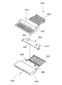
- the connector 10 according to the present embodiment includes two contact members 20U and 20L, a ground member 80, a holding member 130, a shell 140, and two attachment members 150.
- the ground member 80 is made of metal.
- the holding member 130 is made of an insulator.
- the shell 140 is made of metal.
- Each of the attachment members 150 is made of metal.
- the holding member 130 holds the contact members 20U and 20L and the ground member 80 together.
- the shell 140 partially covers the holding member 130.
- Each of the attachment members 150 is accommodated between the holding member 130 and the shell 140.
- Each of the attachment members 150 is connected to the shell 140.
- the two contact members 20U and 20L have the same structure.
- the upper contact member 20U will be mainly described with reference to the drawings.
- the description of the lower contact member 20L is omitted except for matters that require special attention.
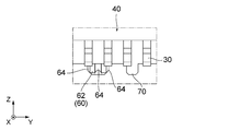
- the contact member 20 ⁇ / b> U includes a plurality of contacts 30 and an alignment member 40.
- Each of the contacts 30 is made of a conductor.
- the alignment member 40 is made of an insulator.
- the alignment member 40 aligns and holds the contacts 30 in the pitch direction (lateral direction: Y direction).
- the contact 30 according to the present embodiment is partially embedded in the alignment member 40 when the alignment member 40 is formed by insert molding. However, the present invention is not limited to this.
- the contact 30 may be press-fitted into the alignment member 40.
- the rear side ( ⁇ X side) of the contact 30 is connected to the pad 210 of the paddle card 200, respectively.
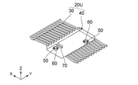
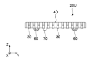
- the alignment member 40 is provided with two concave portions 50, two press-fit projections 60, and island-shaped projections 70.
- the concave portions 50 correspond to the press-fit protrusions 60, respectively.
- each press-fit protrusion 60 protrudes from the inside of the corresponding recess 50 in the protruding direction (downward direction: ⁇ Z direction), and each recessed portion 50 is in the direction opposite to the protruding direction (upper Direction: + Z direction).
- the protruding direction of each press-fitting protrusion 60 of the upper contact member 20U is the downward direction ( ⁇ Z direction)
- the concave direction of each concave portion 50 of the upper contact member 20U is the upward direction (+ Z Direction).
- the protruding direction of each press-fitting protrusion 60 of the lower contact member 20L is the upward direction, and the direction in which each concave portion 50 of the lower contact member 20L is recessed. Is down.
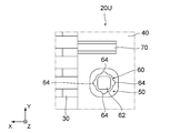
- each press-fitting protrusion 60 has a main protrusion 62 and a plurality of sub protrusions 64.
- the main protrusion 62 extends in the protruding direction.
- Each of the sub protrusions 64 protrudes from the main protrusion 62 in a direction orthogonal to the protruding direction and extends in the protruding direction. That is, the sub projections 64 extend radially from the main projection 62 in a horizontal plane (XY plane) orthogonal to the projecting direction.
- the number of sub-projections 64 is 4, and the sub-projections 64 are arranged at equal intervals in a horizontal plane. Specifically, as shown in FIG.
- the main protrusion 62 has a rounded square shape in the horizontal plane.
- the sub-projections 64 protrude outward from the sides of the main projection 62 so as to have an arc shape in the horizontal plane.
- each of the press-fitting protrusions 60 of the present embodiment is tapered at the tip in the protruding direction.
- the island-shaped protrusion 70 protrudes in the protruding direction and extends in a predetermined direction perpendicular to the protruding direction.
- the predetermined direction of the present embodiment is the front-rear direction (X direction), but the present invention is not limited to this.
- the predetermined direction may be a pitch direction.
- the island-shaped protrusions 70 have a first size in a predetermined direction, and each of the press-fit protrusions 60 has a second size in the predetermined direction. Larger than the second size.
- the size of the island-shaped protrusion 70 in the protruding direction is the same as the size of the press-fit protrusion 60 in the protruding direction.
- the island-shaped protrusion 70 of the present embodiment is tapered at the tip in the protruding direction.
- the ground member 80 includes a flat plate-shaped main portion 90, a lock spring portion 100, and a lock portion 110.
- Each of the lock spring portions 100 can be elastically deformed.
- the lock part 110 locks the other party lock part (not shown).
- the lock part 110 is supported by the lock spring part 100, respectively.
- the main portion 90 of the ground member 80 is formed with four holes 94 and two protrusion accommodating portions 96.
- the two protrusion accommodating portions 96 are equally spaced from a straight line that passes through the center of the ground member 80 in the pitch direction and extends in the front-rear direction.
- the four holes 94 are arranged in a quadrangular shape, and each of the two holes 94 positioned diagonally forms a pair.
- one hole 94 of the two pairs and the other hole 94 of the two pairs are in relation to a straight line passing through the center in the pitch direction of the ground member 80 and extending in the front-rear direction. It arrange
- the projection accommodating portions 96 adjacent to each of the holes 94 positioned on the front side (+ X side) of the main portion 90 form one set.
- two sets of two holes 94 and one protrusion accommodating portion 96 are formed in the main portion 90 of the ground member 80.
- Each pair of holes 94 and the protrusion accommodating portion 96 correspond to one of the upper contact member 20U and the lower contact member 20L.
- the holes 94 correspond to the press-fitting protrusions 60, respectively, and the protrusion accommodating portions 96 respectively correspond to the island-shaped protrusions 70.
- the press-fitting protrusions 60 are press-fitted into the corresponding holes 94, and the island-shaped protrusions 70 are accommodated in the corresponding protrusion accommodating portions 96.
- the tips of the press-fitting protrusions 60 and the island-shaped protrusions 70 are tapered. This makes it easy to press-fit the press-fitting protrusions 60 into the corresponding holes 94 and easily accommodate the island-shaped protrusions 70 in the corresponding protrusion accommodating portions 96.
- the holes 94 and the protrusion accommodating portions 96 are arranged symmetrically with respect to a straight line that passes through the center of the ground member 80 in the pitch direction and extends in the front-rear direction.
- the contact members 20U and 20L can have the same structure. That is, the arrangement of the press-fitting protrusion 60 and the island-shaped protrusion 70 of the contact member 20U does not have to be different from the arrangement of the contact member 20L.
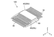
- the holes 94 and the protrusion accommodating portions 96 are arranged as described above, the structure 120 obtained by combining the contact members 20U and 20L with the ground member 80 is shown in FIGS. Thus, it is symmetrical in the vertical and horizontal directions.
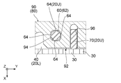
- the thickness (size in the Z direction) of the main portion 90 of the ground member 80 is the height of the press-fitting protrusion 60 and the island-shaped protrusion 70 (projection amount in the Z direction). It is almost the same as each of. It is necessary to consider manufacturing tolerances of the alignment member 40 and the ground member 80. Therefore, precisely, the thickness of the main portion 90 of the ground member 80 is set to be larger than the heights of the press-fit protrusion 60 and the island-shaped protrusion 70. Therefore, in the present embodiment, the press-fitting protrusion 60 and the island-shaped protrusion 70 of the upper contact member 20U do not hit the alignment member 40 of the lower contact member 20L. Similarly, in the present embodiment, the press-fitting protrusion 60 and the island-shaped protrusion 70 of the lower contact member 20L do not hit the alignment member 40 of the upper contact member 20U.
- each of the holes 94 has a rounded quadrangular shape.
- each of the holes 94 is larger than the main protrusion 62 of the corresponding press-fit protrusion 60 in the horizontal plane.
- each of the main protrusions 62 is smaller than the corresponding hole 94 of the main portion 90 of the ground member 80 in the horizontal plane. Therefore, when the press-fitting protrusion 60 is press-fitted into the corresponding hole 94, the entire main projection 62 is received in the corresponding hole 94.
- each of the auxiliary protrusions 64 of the press-fitting protrusion 60 protrudes from the edge of the corresponding hole 94. Therefore, when the press-fitting protrusions 60 are press-fitted into the corresponding holes 94, as can be understood from FIGS. 8 and 15, the sub-protrusions 64 are partially scraped, thereby rattling the ground member 80 with respect to the alignment member 40. Can be installed without It should be noted that shavings generated when the press-fitting protrusions 60 are press-fitted into the corresponding holes 94 are received in the corresponding recesses 50.
- each of the protrusion accommodating portions 96 has an elongated slit shape that reaches the front edge (end portion) 92 of the main portion 90 of the ground member 80 in the horizontal plane. That is, each of the protrusion accommodating portions 96 is open at the front edge 92 of the main portion 90.
- the innermost part in the front-rear direction of each of the protrusion accommodating portions 96 has an arc shape.
- Each of the projection accommodating portions 92 has a certain width from the innermost portion to the front edge 92 of the main portion 90.
- the width of the protrusion accommodating portion 96 (the size in the Y direction) is slightly larger than the size of the corresponding island-shaped protrusion 70 in the pitch direction.
- the island-like protrusions 70 of the present embodiment are received without being cut by the corresponding protrusion accommodating portions 96. That is, the island-shaped protrusions 70 of the present embodiment are not press-fitted into the corresponding protrusion accommodating portions 96.
- the distance between the root 102 of the lock spring portion 100 and the hole 94 is shorter than the distance between the root 102 and the protrusion accommodating portion 96.
- the press-fit protrusion 60 is separated from the root 102 of the lock spring portion 100 by a first distance
- the island-shaped protrusion 70 is separated from the root 102 by a second distance. The distance is shorter than the second distance.
- the press-fitting protrusion 60 is press-fitted into the hole 94 and the island-shaped protrusion 70 is accommodated in the protrusion accommodating portion 96. Then, as shown in FIGS. 11 to 13, the upper contact member 20 ⁇ / b> U, the lower contact member 20 ⁇ / b> L, and the ground member 80 are integrated to form the structure 120. As can be understood from FIGS. 8 and 15, in the present embodiment, the number of the sub-projections 64 is 4, and the sub-projections 64 are arranged at equal intervals in the horizontal plane.
- the center of the main protrusion 62 and the center of the hole 94 are relatively easily aligned in the horizontal plane.
- the auxiliary protrusion 64 is partially cut when the press-fitting protrusion 60 is press-fitted into the corresponding hole 94, there is a possibility that a rotational deviation occurs in the positional relationship between the ground member 80 and the alignment member 40 in the horizontal plane.
- the island-like projections 70 are accommodated in the corresponding projection accommodating portions 96, so that the above-described rotational deviation can be prevented.
- the structure 120 configured as described above is inserted from the rear side ( ⁇ X side) of the holding member 130 and held by the holding member 130 as expected from FIGS. 1 and 2. That is, the contact members 20U and 20L and the ground member 80 are collectively held by the holding member 130.
- the protrusion accommodating portion 96 of the above-described embodiment has reached the front edge 92 of the main portion 90 of the ground member 80, the protrusion accommodating portion 96 may not reach the front edge 92. That is, the protrusion accommodating portion 96 may be a through-hole that is not opened (that is, closed) at the front edge 92 or the like.
- the connector 10 may include only one of the contact members 20U and 20L.
- the connector 10 may include only one contact member 20U, 20L, a pair of holes 94 and a protrusion accommodating portion 96 can be formed in the main portion 90 of the ground member 80.
- the holes 94 and the protrusion accommodating portions 96 formed in the main portion 90 of the ground member 80 are arranged symmetrically with respect to a straight line that passes through the center in the pitch direction of the ground member 80 and extends in the front-rear direction. It had been.
- the structure 120 in which the contact members 20U and 20L are combined with the ground member 80 is symmetrical in the vertical and horizontal directions.
- the hole 94 and the protrusion accommodating portion 96 may not be arranged line-symmetrically.
- the present invention is based on Japanese Patent Application No. 2014-115220 filed with the Japan Patent Office on June 3, 2014, the contents of which are hereby incorporated by reference.
Abstract
Description
20U,20L コンタクト部材
30 コンタクト
40 整列部材
50 凹部
60 圧入突起
62 主突部
64 副突部
70 島状突起
80 グランド部材
90 主部
92 前縁(端部)
94 孔
96 突起収容部
100 ロックバネ部
102 根元
110 ロック部
120 構造体
130 保持部材
140 シェル
150 付属部材
200 パドルカード
210 パッド
900 コネクタ
910 コンタクト部材
920 グランド部材
930 コンタクト
940 整列部材
950 凸部
960 主部
970 孔
Claims (7)
- 前後方向に沿って相手側コネクタと嵌合可能なコネクタであって、
前記コネクタは、コンタクト部材と、グランド部材とを備えており、
前記コンタクト部材は、複数のコンタクトと、整列部材とを備えており、
前記整列部材は、前記コンタクトを前記前後方向と直交するピッチ方向に整列させると共に保持しており、
前記整列部材には、2つの圧入突起と、島状突起とが設けられており、
前記圧入突起の夫々は、前記前後方向と前記ピッチ方向の双方と直交する突出方向に突出しており、
前記島状突起は、前記突出方向に突出すると共に前記突出方向と直交する所定方向に長手を有するように延びており、
前記島状突起は、前記所定方向において第1サイズを有しており、
前記圧入突起は、前記所定方向において第2サイズを有しており、
前記第1サイズは、前記第2サイズよりも大きく、
前記グランド部材は、平板状の主部を有しており、
前記グランド部材の前記主部には、2つの孔と、突起収容部が形成されており、
前記圧入突起は前記孔に夫々圧入されており、前記島状突起は前記突起収容部に収容されている
コネクタ。 - 請求項1記載のコネクタであって、
前記相手側コネクタは、相手側ロック部を有しており、
前記グランド部材は、ロック部と、ロックバネ部とを有しており、
前記ロック部は、前記相手側ロック部をロックし、
前記ロックバネ部は、前記ロック部を支持しており、
前記圧入突起は、前記ロックバネ部の根元から第1距離だけ離れており、
前記島状突起は、前記根元から第2距離だけ離れており、
前記第1距離は、前記第2距離より短い
コネクタ。 - 請求項1又は請求項2記載のコネクタであって、
前記主部は、前記前後方向において1つの端部を有しており、
前記突起収容部は、前記突出方向と直交する平面内において、前記グランド部材の前記主部の前記端部まで達している
コネクタ。 - 請求項1乃至請求項3のいずれかに記載のコネクタであって、
前記コンタクト部材を2つ備えており、
2つの前記コンタクト部材は、互いに同一構造を有しており、
前記グランド部材の前記主部には、夫々が前記2つの孔と前記突起収容部からなる2組が形成されており、
前記2組の一方の前記2つの孔と前記2組の残りの一方の前記2つの孔とは、前記グランド部材の前記ピッチ方向における中心を通り且つ前記前後方向に延びる直線に対して互いに線対称となるように配置されている
コネクタ。 - 請求項1乃至請求項4のいずれかに記載のコネクタであって、
前記圧入突起の夫々は、主突部と、複数の副突部とを有しており、
前記主突部は、前記突出方向に延びており、
前記突出方向と直交する平面内において、前記主突部は、前記グランド部材の前記主部の対応する孔よりも小さく、
前記副突部の夫々は、前記主突部から前記突出方向と直交する方向に突出すると共に前記突出方向に延びている
コネクタ。 - 請求項1乃至請求項5のいずれかに記載のコネクタであって、
前記整列部材には、2つの凹部が形成されており、
前記凹部は、前記圧入突起に夫々対応しており、
前記凹部の夫々は、前記突出方向と逆方向に凹んでおり、
前記圧入突起は、対応する前記凹部の内部から前記突出方向に突出している
コネクタ。 - 請求項1乃至請求項6のいずれかに記載のコネクタであって、
前記コンタクト部材と前記グランド部材をまとめて保持する保持部材を更に備えている
コネクタ。
Priority Applications (3)
| Application Number | Priority Date | Filing Date | Title |
|---|---|---|---|
| KR1020167031678A KR101823419B1 (ko) | 2014-06-03 | 2015-05-15 | 커넥터 |
| US15/309,970 US9728885B2 (en) | 2014-06-03 | 2015-05-15 | Connector |
| CN201580025245.2A CN106463874B (zh) | 2014-06-03 | 2015-05-15 | 连接器 |
Applications Claiming Priority (2)
| Application Number | Priority Date | Filing Date | Title |
|---|---|---|---|
| JP2014-115220 | 2014-06-03 | ||
| JP2014115220A JP6293580B2 (ja) | 2014-06-03 | 2014-06-03 | コネクタ |
Publications (1)
| Publication Number | Publication Date |
|---|---|
| WO2015186495A1 true WO2015186495A1 (ja) | 2015-12-10 |
Family
ID=54766571
Family Applications (1)
| Application Number | Title | Priority Date | Filing Date |
|---|---|---|---|
| PCT/JP2015/064093 WO2015186495A1 (ja) | 2014-06-03 | 2015-05-15 | コネクタ |
Country Status (6)
| Country | Link |
|---|---|
| US (1) | US9728885B2 (ja) |
| JP (1) | JP6293580B2 (ja) |
| KR (1) | KR101823419B1 (ja) |
| CN (1) | CN106463874B (ja) |
| TW (1) | TWI605644B (ja) |
| WO (1) | WO2015186495A1 (ja) |
Cited By (1)
| Publication number | Priority date | Publication date | Assignee | Title |
|---|---|---|---|---|
| US11258214B2 (en) | 2015-11-06 | 2022-02-22 | Molex, Llc | Compact high speed connector |
Families Citing this family (26)
| Publication number | Priority date | Publication date | Assignee | Title |
|---|---|---|---|---|
| US9843148B2 (en) * | 2013-07-19 | 2017-12-12 | Foxconn Interconnect Technology Limited | Flippable electrical connector |
| CN204243363U (zh) * | 2014-02-21 | 2015-04-01 | 番禺得意精密电子工业有限公司 | 电连接器 |
| JP7191501B2 (ja) * | 2014-06-24 | 2022-12-19 | 周賢 蔡 | 双方向コネクタ |
| US20220006247A1 (en) * | 2014-06-24 | 2022-01-06 | Chou Hsien Tsai | Reversible dual-position electric connector |
| US11038310B2 (en) * | 2014-06-24 | 2021-06-15 | Kiwi Intellectual Assets Corporation | Reversible dual-position electric connector |
| CN204216267U (zh) | 2014-07-15 | 2015-03-18 | 番禺得意精密电子工业有限公司 | 电连接器 |
| JP5905952B1 (ja) * | 2014-11-20 | 2016-04-20 | 日本航空電子工業株式会社 | コネクタ |
| WO2017022355A1 (ja) * | 2015-07-31 | 2017-02-09 | 日本航空電子工業株式会社 | コネクタ及びコネクタの製造方法 |
| CN105119081A (zh) * | 2015-09-09 | 2015-12-02 | 连展科技(深圳)有限公司 | 插头电连接器 |
| JP6058771B1 (ja) * | 2015-10-13 | 2017-01-11 | 日本航空電子工業株式会社 | レセプタクルコネクタ |
| JP6390663B2 (ja) * | 2016-05-18 | 2018-09-19 | 第一精工株式会社 | 電気コネクタ及びその製造方法 |
| CN205944586U (zh) * | 2016-07-26 | 2017-02-08 | 番禺得意精密电子工业有限公司 | 电连接器组件 |
| CN206076581U (zh) * | 2016-09-14 | 2017-04-05 | 连展科技(深圳)有限公司 | 插座电连接器 |
| CN206236856U (zh) * | 2016-09-22 | 2017-06-09 | 番禺得意精密电子工业有限公司 | 复合式连接器 |
| CN206461134U (zh) * | 2016-11-23 | 2017-09-01 | 番禺得意精密电子工业有限公司 | 插头连接器 |
| CN206461182U (zh) * | 2016-11-23 | 2017-09-01 | 番禺得意精密电子工业有限公司 | 插头连接器 |
| CN206441936U (zh) * | 2016-11-30 | 2017-08-25 | 富士康(昆山)电脑接插件有限公司 | 电连接器 |
| CN206532959U (zh) * | 2016-12-08 | 2017-09-29 | 番禺得意精密电子工业有限公司 | 线缆连接器组件 |
| CN207098100U (zh) * | 2016-12-08 | 2018-03-13 | 番禺得意精密电子工业有限公司 | 线缆连接器组件 |
| JP6840636B2 (ja) * | 2017-07-19 | 2021-03-10 | 日本航空電子工業株式会社 | 防水コネクタ |
| CN108923156B (zh) * | 2017-11-02 | 2022-07-26 | 富士康(昆山)电脑接插件有限公司 | 电连接器 |
| CN110970763B (zh) * | 2018-09-28 | 2021-08-20 | 富士康(昆山)电脑接插件有限公司 | 电连接器 |
| CN109390803B (zh) * | 2018-10-09 | 2020-10-30 | 番禺得意精密电子工业有限公司 | 电连接器 |
| CN109390715B (zh) * | 2018-10-09 | 2020-11-24 | 番禺得意精密电子工业有限公司 | 电连接器 |
| JP7066661B2 (ja) * | 2019-08-07 | 2022-05-13 | 矢崎総業株式会社 | コネクタ |
| CN214478080U (zh) * | 2021-01-29 | 2021-10-22 | 立讯精密工业股份有限公司 | 电连接器 |
Citations (6)
| Publication number | Priority date | Publication date | Assignee | Title |
|---|---|---|---|---|
| JPH02216776A (ja) * | 1989-02-17 | 1990-08-29 | Elco Internatl:Kk | 表面実装コネクタ |
| JPH0828255B2 (ja) * | 1991-09-09 | 1996-03-21 | 鴻海精密工業股▲ふん▼有限公司 | 埋込み形支柱部を有する電気コネクタ |
| JP3324995B2 (ja) * | 1999-04-07 | 2002-09-17 | タイコエレクトロニクスアンプ株式会社 | 電気コネクタ |
| JP3703551B2 (ja) * | 1996-01-17 | 2005-10-05 | 富士通コンポーネント株式会社 | コネクタ |
| JP2005327701A (ja) * | 2004-05-11 | 2005-11-24 | Shukuran Yori | 端子ポートのプラスチック芯がある端子列のコネクター |
| JP4219088B2 (ja) * | 1997-08-20 | 2009-02-04 | エフシーアイ・アメリカズ・テクノロジー・インコーポレーテッド | 高速度モジュラー電気コネクタに使用されるレセプタクル |
Family Cites Families (86)
| Publication number | Priority date | Publication date | Assignee | Title |
|---|---|---|---|---|
| CN1104065C (zh) * | 1997-08-20 | 2003-03-26 | 连接器系统工艺公司 | 高速标准电连接器和所用的插座 |
| US6305976B1 (en) | 2000-04-07 | 2001-10-23 | Amp (Japan), Ltd. | Electrical connector with planar mounting members |
| JP3883447B2 (ja) * | 2002-02-26 | 2007-02-21 | 矢崎総業株式会社 | 計器の基板固定構造 |
| TWM250341U (en) | 2003-09-05 | 2004-11-11 | Hon Hai Prec Ind Co Ltd | Electrical connector |
| US9490579B2 (en) * | 2013-07-19 | 2016-11-08 | Foxconn Interconnect Technology Limited | Flippable Electrical Connector |
| US9660400B2 (en) * | 2013-07-19 | 2017-05-23 | Foxconn Interconnect Technology Limited | Flippable electrical connector |
| US9350126B2 (en) * | 2013-07-19 | 2016-05-24 | Foxconn Interconnect Technology Limited | Electrical connector having a receptacle with a shielding plate and a mating plug with metallic side arms |
| US9484681B2 (en) * | 2013-07-19 | 2016-11-01 | Foxconn Interconnect Technology Limited | Flippable electrical connector |
| US9520677B2 (en) * | 2013-07-19 | 2016-12-13 | Foxconn Interconnect Technology Limited | Flippable electrical connector |
| US9356400B2 (en) * | 2013-07-19 | 2016-05-31 | Foxconn Interconnect Technology Limited | Flippable electrical connector |
| US9755368B2 (en) * | 2013-07-19 | 2017-09-05 | Foxconn Interconnect Technology Limited | Flippable electrical connector |
| TWI607609B (zh) * | 2014-03-24 | 2017-12-01 | 連展科技股份有限公司 | 插頭電連接器 |
| US9450342B2 (en) * | 2014-04-04 | 2016-09-20 | Foxconn Interconnect Technology Limited | Plug connector assembly having improved anti-EMI performance |
| TWM494421U (zh) * | 2014-04-21 | 2015-01-21 | Advanced Connectek Inc | 插座電連接器及插頭電連接器 |
| TWI544694B (zh) * | 2014-05-15 | 2016-08-01 | Advanced Connectek Inc | Plug electrical connector and socket electrical connector |
| TWM493185U (zh) * | 2014-08-29 | 2015-01-01 | Chant Sincere Co Ltd | 序列匯流排連接器 |
| CN204464639U (zh) * | 2014-05-23 | 2015-07-08 | 诠欣股份有限公司 | 电连接器 |
| US9660389B2 (en) * | 2014-05-26 | 2017-05-23 | Apple Inc. | Additional ground paths for connectors having reduced pin counts |
| US9515439B2 (en) * | 2014-05-26 | 2016-12-06 | Apple Inc. | Connector insert assembly |
| CN106463890B (zh) * | 2014-06-02 | 2018-11-23 | 日本航空电子工业株式会社 | 连接器 |
| JP6278841B2 (ja) * | 2014-06-02 | 2018-02-14 | 日本航空電子工業株式会社 | コネクタ |
| JP6422675B2 (ja) * | 2014-06-03 | 2018-11-14 | 日本航空電子工業株式会社 | コネクタ |
| US9281626B2 (en) * | 2014-06-13 | 2016-03-08 | Lotes Co., Ltd | Mating connector |
| US9472907B2 (en) * | 2014-06-30 | 2016-10-18 | Advanced-Connectek Inc. | Electrical plug connector |
| US9478916B2 (en) * | 2014-06-30 | 2016-10-25 | Advanced-Connectek Inc. | Electrical plug connector |
| US9362680B2 (en) * | 2014-06-30 | 2016-06-07 | Advanced-Connectek Inc. | Electrical plug connector |
| US9397433B2 (en) * | 2014-06-30 | 2016-07-19 | Advanced-Connectek Inc. | Electrical plug connector |
| CN105305121B (zh) * | 2014-07-11 | 2018-06-01 | 富士康(昆山)电脑接插件有限公司 | 线缆连接器组件 |
| CN105375231B (zh) * | 2014-07-11 | 2018-12-11 | 富士康(昆山)电脑接插件有限公司 | 线缆连接器组件及其制造方法 |
| CN204216267U (zh) * | 2014-07-15 | 2015-03-18 | 番禺得意精密电子工业有限公司 | 电连接器 |
| CN204011840U (zh) * | 2014-07-29 | 2014-12-10 | 康联精密机电(深圳)有限公司 | 高速传输信号连接器 |
| TWI563751B (en) * | 2014-08-06 | 2016-12-21 | Advanced Connectek Inc | Electrical connector of plug type |
| CN105449466B (zh) * | 2014-08-07 | 2019-01-11 | 富士康(昆山)电脑接插件有限公司 | 线缆连接器组件 |
| TWI573335B (zh) * | 2014-08-13 | 2017-03-01 | 鴻騰精密科技股份有限公司 | 電連接器及其製造方法 |
| JP6280001B2 (ja) * | 2014-08-22 | 2018-02-14 | ホシデン株式会社 | コネクタ |
| TWI578633B (zh) * | 2014-08-22 | 2017-04-11 | 鴻騰精密科技股份有限公司 | 電連接器及其製造方法 |
| JP6259735B2 (ja) * | 2014-08-28 | 2018-01-10 | ホシデン株式会社 | コネクタ |
| TWI577094B (zh) * | 2014-08-28 | 2017-04-01 | 連展科技股份有限公司 | 插頭電連接器 |
| CN105470690A (zh) * | 2014-09-05 | 2016-04-06 | 凡甲电子(苏州)有限公司 | 电连接器及其制造方法 |
| CN105470733B (zh) * | 2014-09-05 | 2018-01-09 | 凡甲电子(苏州)有限公司 | 电连接器 |
| CN204143896U (zh) * | 2014-09-12 | 2015-02-04 | 富士康(昆山)电脑接插件有限公司 | 线缆连接器组件 |
| US20160079711A1 (en) * | 2014-09-17 | 2016-03-17 | Kuang Ying Computer Equipment Co., Ltd. | Electronic Connector |
| US9843142B2 (en) * | 2014-09-30 | 2017-12-12 | Apple Inc. | Connector receptacle having good signal integrity |
| CN204205157U (zh) * | 2014-10-10 | 2015-03-11 | 东莞讯滔电子有限公司 | 电连接器 |
| CN104362450B (zh) * | 2014-11-06 | 2023-05-05 | 连展科技电子(昆山)有限公司 | 具有双向插接功能的插头连接器 |
| CN204271341U (zh) * | 2014-11-07 | 2015-04-15 | 深圳市正耀科技有限公司 | 一种连接器插头 |
| CN204243263U (zh) * | 2014-11-14 | 2015-04-01 | 富士康(昆山)电脑接插件有限公司 | 电源连接器组件 |
| CN204315807U (zh) * | 2014-11-14 | 2015-05-06 | 富士康(昆山)电脑接插件有限公司 | 线缆连接器组件 |
| TWM518835U (zh) * | 2014-11-17 | 2016-03-11 | 宣德科技股份有限公司 | 電子連接器結構 |
| CN104377509A (zh) * | 2014-11-19 | 2015-02-25 | 连展科技电子(昆山)有限公司 | 插头电连接器 |
| TWI586049B (zh) * | 2014-11-21 | 2017-06-01 | 連展科技股份有限公司 | 屏蔽接地之插頭電連接器 |
| CN105703137B (zh) * | 2014-11-25 | 2018-10-02 | 富士康(昆山)电脑接插件有限公司 | 线缆连接器组件及其制造方法 |
| US9373916B2 (en) * | 2014-11-26 | 2016-06-21 | Triple Win Precision Technology Co., Ltd. | Receptacle structure |
| CN104638406A (zh) * | 2014-11-27 | 2015-05-20 | 连展科技电子(昆山)有限公司 | 插头电连接器组件 |
| CN104505663A (zh) * | 2014-11-27 | 2015-04-08 | 连展科技电子(昆山)有限公司 | 插头电连接器 |
| CN104518321B (zh) * | 2014-11-27 | 2023-05-05 | 连展科技电子(昆山)有限公司 | 插头电连接器 |
| CN104505642B (zh) * | 2014-11-27 | 2024-04-02 | 连展科技电子(昆山)有限公司 | 插头电连接器 |
| CN204315839U (zh) * | 2014-12-16 | 2015-05-06 | 富士康(昆山)电脑接插件有限公司 | 线缆连接器组件 |
| CN105789930B (zh) * | 2014-12-16 | 2019-01-11 | 富士康(昆山)电脑接插件有限公司 | 线缆连接器组件及其制造方法 |
| CN104538797B (zh) * | 2014-12-23 | 2023-11-17 | 连展科技电子(昆山)有限公司 | 防干扰插头电连接器 |
| CN204349021U (zh) * | 2014-12-30 | 2015-05-20 | 深圳市得润电子股份有限公司 | 一种电连接器以及线缆连接器组件 |
| US9466918B2 (en) * | 2015-01-08 | 2016-10-11 | Simula Technology Inc. | Signal connector having grounding member for pressing and preventing from short-circuit |
| CN104577637B (zh) * | 2015-01-08 | 2017-05-10 | 番禺得意精密电子工业有限公司 | 电连接器的制造方法 |
| US20160226204A1 (en) * | 2015-01-30 | 2016-08-04 | Ken Chen | Electrical connector |
| TWM505078U (zh) * | 2015-02-06 | 2015-07-11 | 詮欣股份有限公司 | 序列匯流排連接器 |
| TWM527166U (zh) * | 2015-03-09 | 2016-08-11 | Advanced Connectek Inc | 直立型插座電連接器 |
| CN104682137A (zh) * | 2015-03-09 | 2015-06-03 | 连展科技(深圳)有限公司 | 插头电连接器 |
| CN104821444A (zh) * | 2015-03-30 | 2015-08-05 | 连展科技电子(昆山)有限公司 | 直插式插头电连接器 |
| US9350128B1 (en) * | 2015-04-03 | 2016-05-24 | Cheng Uei Precision Industry Co., Ltd. | Adapter |
| CN104882700A (zh) * | 2015-04-24 | 2015-09-02 | 连展科技(深圳)有限公司 | 插头电连接器 |
| CN104852175A (zh) * | 2015-04-28 | 2015-08-19 | 连展科技(深圳)有限公司 | 插头电连接器及其成型方法 |
| TWM514669U (zh) * | 2015-04-30 | 2015-12-21 | Kinnexa Inc | 電連接器之結構改良(一) |
| CN104852178B (zh) * | 2015-05-20 | 2018-01-16 | 连展科技(深圳)有限公司 | 电连接器 |
| CN204696364U (zh) * | 2015-06-01 | 2015-10-07 | 富士康(昆山)电脑接插件有限公司 | 线缆连接器组件 |
| CN105529554B (zh) * | 2015-06-03 | 2019-05-31 | 连展科技(深圳)有限公司 | 插头电连接器 |
| US9774111B2 (en) * | 2015-06-09 | 2017-09-26 | Molex, Llc | Cable connector assembly with multi-layered circuit board |
| CN204835012U (zh) * | 2015-06-29 | 2015-12-02 | 富士康(昆山)电脑接插件有限公司 | 线缆连接器组件 |
| CN105186155B (zh) * | 2015-07-30 | 2018-04-13 | 凡甲电子(苏州)有限公司 | 线缆连接器 |
| CN205081257U (zh) * | 2015-08-14 | 2016-03-09 | 番禺得意精密电子工业有限公司 | 电连接器 |
| US9455535B1 (en) * | 2015-08-30 | 2016-09-27 | Cheng Uei Precision Industry Co., Ltd. | Plug connector |
| TWI553977B (zh) * | 2015-09-02 | 2016-10-11 | 威盛電子股份有限公司 | 轉接卡及插頭電纜總成 |
| CN105119081A (zh) * | 2015-09-09 | 2015-12-02 | 连展科技(深圳)有限公司 | 插头电连接器 |
| CN105119087A (zh) * | 2015-09-09 | 2015-12-02 | 连展科技(深圳)有限公司 | 插头电连接器 |
| JP6325501B2 (ja) * | 2015-09-29 | 2018-05-16 | 日本航空電子工業株式会社 | コネクタ |
| US9601883B1 (en) * | 2015-11-05 | 2017-03-21 | Kuang Ying Computer Equipment Co., Ltd. | USB connector |
| US9564715B1 (en) * | 2016-01-28 | 2017-02-07 | Cheng Uei Precision Industry Co., Ltd. | Electrical connector |
-
2014
- 2014-06-03 JP JP2014115220A patent/JP6293580B2/ja active Active
-
2015
- 2015-05-15 CN CN201580025245.2A patent/CN106463874B/zh active Active
- 2015-05-15 US US15/309,970 patent/US9728885B2/en active Active
- 2015-05-15 WO PCT/JP2015/064093 patent/WO2015186495A1/ja active Application Filing
- 2015-05-15 KR KR1020167031678A patent/KR101823419B1/ko active IP Right Grant
- 2015-05-19 TW TW104115839A patent/TWI605644B/zh active
Patent Citations (6)
| Publication number | Priority date | Publication date | Assignee | Title |
|---|---|---|---|---|
| JPH02216776A (ja) * | 1989-02-17 | 1990-08-29 | Elco Internatl:Kk | 表面実装コネクタ |
| JPH0828255B2 (ja) * | 1991-09-09 | 1996-03-21 | 鴻海精密工業股▲ふん▼有限公司 | 埋込み形支柱部を有する電気コネクタ |
| JP3703551B2 (ja) * | 1996-01-17 | 2005-10-05 | 富士通コンポーネント株式会社 | コネクタ |
| JP4219088B2 (ja) * | 1997-08-20 | 2009-02-04 | エフシーアイ・アメリカズ・テクノロジー・インコーポレーテッド | 高速度モジュラー電気コネクタに使用されるレセプタクル |
| JP3324995B2 (ja) * | 1999-04-07 | 2002-09-17 | タイコエレクトロニクスアンプ株式会社 | 電気コネクタ |
| JP2005327701A (ja) * | 2004-05-11 | 2005-11-24 | Shukuran Yori | 端子ポートのプラスチック芯がある端子列のコネクター |
Cited By (1)
| Publication number | Priority date | Publication date | Assignee | Title |
|---|---|---|---|---|
| US11258214B2 (en) | 2015-11-06 | 2022-02-22 | Molex, Llc | Compact high speed connector |
Also Published As
| Publication number | Publication date |
|---|---|
| CN106463874B (zh) | 2018-11-13 |
| KR20160143823A (ko) | 2016-12-14 |
| TWI605644B (zh) | 2017-11-11 |
| US9728885B2 (en) | 2017-08-08 |
| TW201607166A (zh) | 2016-02-16 |
| CN106463874A (zh) | 2017-02-22 |
| JP2015230771A (ja) | 2015-12-21 |
| US20170149164A1 (en) | 2017-05-25 |
| KR101823419B1 (ko) | 2018-01-30 |
| JP6293580B2 (ja) | 2018-03-14 |
Similar Documents
| Publication | Publication Date | Title |
|---|---|---|
| WO2015186495A1 (ja) | コネクタ | |
| JP2017016897A (ja) | 基板対基板コネクタおよびコネクタ | |
| WO2015186491A1 (ja) | コネクタ | |
| US8944829B2 (en) | Connector | |
| WO2015186498A1 (ja) | コネクタ | |
| JP2015035352A (ja) | コネクタ | |
| TW201126834A (en) | Electrical connector | |
| US20170324176A1 (en) | Board connector | |
| KR101560887B1 (ko) | 커넥터 | |
| US20190157811A1 (en) | Connector | |
| JP2015220005A (ja) | 基板対基板用コネクタ | |
| CN110277278B (zh) | 插座 | |
| KR20130124353A (ko) | 콘택트 및 콘택트를 갖는 커넥터 | |
| JP2013526767A (ja) | コネクタ | |
| JP2015008053A (ja) | コネクタおよび当該コネクタに用いられるヘッダならびにソケット | |
| JP2017103916A (ja) | 係合構造、電子部品モジュール、および電気接続箱 | |
| JP6120168B2 (ja) | コネクタおよび当該コネクタに用いられるヘッダならびにソケット | |
| JP2013161540A (ja) | コネクタ | |
| JP2009110697A (ja) | コネクタ | |
| JP2012256477A (ja) | 基板用コネクタの取付構造 | |
| JP2019096483A (ja) | ソケット端子およびソケットコネクタ | |
| JP2015204139A (ja) | Usbレセプタクル | |
| JP5999638B2 (ja) | 電子ユニット取付構造 | |
| JP4794977B2 (ja) | 電気接続箱 | |
| US9022802B2 (en) | Terminal module |
Legal Events
| Date | Code | Title | Description |
|---|---|---|---|
| 121 | Ep: the epo has been informed by wipo that ep was designated in this application |
Ref document number: 15803073 Country of ref document: EP Kind code of ref document: A1 |
|
| WWE | Wipo information: entry into national phase |
Ref document number: 15309970 Country of ref document: US |
|
| ENP | Entry into the national phase |
Ref document number: 20167031678 Country of ref document: KR Kind code of ref document: A |
|
| NENP | Non-entry into the national phase |
Ref country code: DE |
|
| 122 | Ep: pct application non-entry in european phase |
Ref document number: 15803073 Country of ref document: EP Kind code of ref document: A1 |