WO2015129827A1 - 回転速度検出装置付転がり軸受ユニット - Google Patents
回転速度検出装置付転がり軸受ユニット Download PDFInfo
- Publication number
- WO2015129827A1 WO2015129827A1 PCT/JP2015/055710 JP2015055710W WO2015129827A1 WO 2015129827 A1 WO2015129827 A1 WO 2015129827A1 JP 2015055710 W JP2015055710 W JP 2015055710W WO 2015129827 A1 WO2015129827 A1 WO 2015129827A1
- Authority
- WO
- WIPO (PCT)
- Prior art keywords
- cap
- axial direction
- axial
- outer ring
- fitting
- Prior art date
Links
Images


Classifications
-
- F—MECHANICAL ENGINEERING; LIGHTING; HEATING; WEAPONS; BLASTING
- F16—ENGINEERING ELEMENTS AND UNITS; GENERAL MEASURES FOR PRODUCING AND MAINTAINING EFFECTIVE FUNCTIONING OF MACHINES OR INSTALLATIONS; THERMAL INSULATION IN GENERAL
- F16C—SHAFTS; FLEXIBLE SHAFTS; ELEMENTS OR CRANKSHAFT MECHANISMS; ROTARY BODIES OTHER THAN GEARING ELEMENTS; BEARINGS
- F16C41/00—Other accessories, e.g. devices integrated in the bearing not relating to the bearing function as such
- F16C41/007—Encoders, e.g. parts with a plurality of alternating magnetic poles
-
- B—PERFORMING OPERATIONS; TRANSPORTING
- B60—VEHICLES IN GENERAL
- B60B—VEHICLE WHEELS; CASTORS; AXLES FOR WHEELS OR CASTORS; INCREASING WHEEL ADHESION
- B60B27/00—Hubs
- B60B27/0005—Hubs with ball bearings
-
- B—PERFORMING OPERATIONS; TRANSPORTING
- B60—VEHICLES IN GENERAL
- B60B—VEHICLE WHEELS; CASTORS; AXLES FOR WHEELS OR CASTORS; INCREASING WHEEL ADHESION
- B60B27/00—Hubs
- B60B27/0047—Hubs characterised by functional integration of other elements
- B60B27/0068—Hubs characterised by functional integration of other elements the element being a sensor
-
- B—PERFORMING OPERATIONS; TRANSPORTING
- B60—VEHICLES IN GENERAL
- B60B—VEHICLE WHEELS; CASTORS; AXLES FOR WHEELS OR CASTORS; INCREASING WHEEL ADHESION
- B60B27/00—Hubs
- B60B27/0073—Hubs characterised by sealing means
-
- B—PERFORMING OPERATIONS; TRANSPORTING
- B60—VEHICLES IN GENERAL
- B60B—VEHICLE WHEELS; CASTORS; AXLES FOR WHEELS OR CASTORS; INCREASING WHEEL ADHESION
- B60B27/00—Hubs
- B60B27/0094—Hubs one or more of the bearing races are formed by the hub
-
- F—MECHANICAL ENGINEERING; LIGHTING; HEATING; WEAPONS; BLASTING
- F16—ENGINEERING ELEMENTS AND UNITS; GENERAL MEASURES FOR PRODUCING AND MAINTAINING EFFECTIVE FUNCTIONING OF MACHINES OR INSTALLATIONS; THERMAL INSULATION IN GENERAL
- F16C—SHAFTS; FLEXIBLE SHAFTS; ELEMENTS OR CRANKSHAFT MECHANISMS; ROTARY BODIES OTHER THAN GEARING ELEMENTS; BEARINGS
- F16C19/00—Bearings with rolling contact, for exclusively rotary movement
- F16C19/02—Bearings with rolling contact, for exclusively rotary movement with bearing balls essentially of the same size in one or more circular rows
- F16C19/14—Bearings with rolling contact, for exclusively rotary movement with bearing balls essentially of the same size in one or more circular rows for both radial and axial load
- F16C19/18—Bearings with rolling contact, for exclusively rotary movement with bearing balls essentially of the same size in one or more circular rows for both radial and axial load with two or more rows of balls
- F16C19/181—Bearings with rolling contact, for exclusively rotary movement with bearing balls essentially of the same size in one or more circular rows for both radial and axial load with two or more rows of balls with angular contact
- F16C19/183—Bearings with rolling contact, for exclusively rotary movement with bearing balls essentially of the same size in one or more circular rows for both radial and axial load with two or more rows of balls with angular contact with two rows at opposite angles
- F16C19/184—Bearings with rolling contact, for exclusively rotary movement with bearing balls essentially of the same size in one or more circular rows for both radial and axial load with two or more rows of balls with angular contact with two rows at opposite angles in O-arrangement
- F16C19/186—Bearings with rolling contact, for exclusively rotary movement with bearing balls essentially of the same size in one or more circular rows for both radial and axial load with two or more rows of balls with angular contact with two rows at opposite angles in O-arrangement with three raceways provided integrally on parts other than race rings, e.g. third generation hubs
-
- F—MECHANICAL ENGINEERING; LIGHTING; HEATING; WEAPONS; BLASTING
- F16—ENGINEERING ELEMENTS AND UNITS; GENERAL MEASURES FOR PRODUCING AND MAINTAINING EFFECTIVE FUNCTIONING OF MACHINES OR INSTALLATIONS; THERMAL INSULATION IN GENERAL
- F16C—SHAFTS; FLEXIBLE SHAFTS; ELEMENTS OR CRANKSHAFT MECHANISMS; ROTARY BODIES OTHER THAN GEARING ELEMENTS; BEARINGS
- F16C33/00—Parts of bearings; Special methods for making bearings or parts thereof
- F16C33/72—Sealings
- F16C33/723—Shaft end sealing means, e.g. cup-shaped caps or covers
-
- F—MECHANICAL ENGINEERING; LIGHTING; HEATING; WEAPONS; BLASTING
- F16—ENGINEERING ELEMENTS AND UNITS; GENERAL MEASURES FOR PRODUCING AND MAINTAINING EFFECTIVE FUNCTIONING OF MACHINES OR INSTALLATIONS; THERMAL INSULATION IN GENERAL
- F16C—SHAFTS; FLEXIBLE SHAFTS; ELEMENTS OR CRANKSHAFT MECHANISMS; ROTARY BODIES OTHER THAN GEARING ELEMENTS; BEARINGS
- F16C33/00—Parts of bearings; Special methods for making bearings or parts thereof
- F16C33/72—Sealings
- F16C33/76—Sealings of ball or roller bearings
- F16C33/78—Sealings of ball or roller bearings with a diaphragm, disc, or ring, with or without resilient members
- F16C33/7816—Details of the sealing or parts thereof, e.g. geometry, material
- F16C33/783—Details of the sealing or parts thereof, e.g. geometry, material of the mounting region
-
- F—MECHANICAL ENGINEERING; LIGHTING; HEATING; WEAPONS; BLASTING
- F16—ENGINEERING ELEMENTS AND UNITS; GENERAL MEASURES FOR PRODUCING AND MAINTAINING EFFECTIVE FUNCTIONING OF MACHINES OR INSTALLATIONS; THERMAL INSULATION IN GENERAL
- F16C—SHAFTS; FLEXIBLE SHAFTS; ELEMENTS OR CRANKSHAFT MECHANISMS; ROTARY BODIES OTHER THAN GEARING ELEMENTS; BEARINGS
- F16C35/00—Rigid support of bearing units; Housings, e.g. caps, covers
-
- G—PHYSICS
- G01—MEASURING; TESTING
- G01P—MEASURING LINEAR OR ANGULAR SPEED, ACCELERATION, DECELERATION, OR SHOCK; INDICATING PRESENCE, ABSENCE, OR DIRECTION, OF MOVEMENT
- G01P3/00—Measuring linear or angular speed; Measuring differences of linear or angular speeds
- G01P3/42—Devices characterised by the use of electric or magnetic means
- G01P3/44—Devices characterised by the use of electric or magnetic means for measuring angular speed
- G01P3/443—Devices characterised by the use of electric or magnetic means for measuring angular speed mounted in bearings
-
- B—PERFORMING OPERATIONS; TRANSPORTING
- B60—VEHICLES IN GENERAL
- B60B—VEHICLE WHEELS; CASTORS; AXLES FOR WHEELS OR CASTORS; INCREASING WHEEL ADHESION
- B60B27/00—Hubs
- B60B27/06—Hubs adapted to be fixed on axle
- B60B27/065—Hubs adapted to be fixed on axle characterised by the fixation of the hub to the axle
-
- F—MECHANICAL ENGINEERING; LIGHTING; HEATING; WEAPONS; BLASTING
- F16—ENGINEERING ELEMENTS AND UNITS; GENERAL MEASURES FOR PRODUCING AND MAINTAINING EFFECTIVE FUNCTIONING OF MACHINES OR INSTALLATIONS; THERMAL INSULATION IN GENERAL
- F16C—SHAFTS; FLEXIBLE SHAFTS; ELEMENTS OR CRANKSHAFT MECHANISMS; ROTARY BODIES OTHER THAN GEARING ELEMENTS; BEARINGS
- F16C2233/00—Monitoring condition, e.g. temperature, load, vibration
-
- F—MECHANICAL ENGINEERING; LIGHTING; HEATING; WEAPONS; BLASTING
- F16—ENGINEERING ELEMENTS AND UNITS; GENERAL MEASURES FOR PRODUCING AND MAINTAINING EFFECTIVE FUNCTIONING OF MACHINES OR INSTALLATIONS; THERMAL INSULATION IN GENERAL
- F16C—SHAFTS; FLEXIBLE SHAFTS; ELEMENTS OR CRANKSHAFT MECHANISMS; ROTARY BODIES OTHER THAN GEARING ELEMENTS; BEARINGS
- F16C2326/00—Articles relating to transporting
- F16C2326/01—Parts of vehicles in general
- F16C2326/02—Wheel hubs or castors
Definitions
- This invention relates to the improvement of a rolling bearing unit with a rotational speed detector for detecting the rotational speed of the wheel while supporting the wheel (driven wheel) of the automobile rotatably with respect to the suspension device.
- Rolling bearing units are used to support the wheels of automobiles rotatably with respect to the suspension system. Moreover, in order to control an anti-lock brake system (ABS) or a traction control system (TCS), it is necessary to detect the rotational speed of a wheel. For this reason, the rolling bearing unit with a rotational speed detection device incorporating a rotational speed detection device in the rolling bearing unit can support the wheel rotatably with respect to the suspension device, and can detect the rotational speed of the wheel. In recent years, it has been widely performed.
- Patent Document 1 describes a structure as shown in FIGS. 12 and 13 as an example of a conventional structure of a rolling bearing unit with a rotational speed detection device used for such a purpose.
- This rolling bearing unit 1 with a rotational speed detection device having a conventional structure rotatably supports a hub 3 as a rotating ring on the inner diameter side of an outer ring 2 as a stationary ring.
- the outer ring 2 has double-row outer ring raceways 4a and 4b on the inner peripheral surface, and a stationary flange 5 on the outer peripheral surface. Further, the outer ring 2 is supported and supported by a knuckle (not shown) that constitutes a suspension device in use.
- the hub 3 is a combination of a hub body 6 and an inner ring 7.
- the hub 3 has double-row inner ring raceways 8 a and 8 b on the outer peripheral surface, and is supported concentrically with the outer ring 2 on the inner diameter side of the outer ring 2. Yes.
- the inner ring raceway 8a in the axially outer row is directly formed at the axially intermediate portion of the outer peripheral surface of the hub body 6, and also the inner end of the axial direction (the inner side in the axial direction is assembled to the suspension device.
- the inner ring 7 having the inner ring raceway 8b in the axially inner row formed on the outer peripheral surface is externally fitted and fixed to the small-diameter step portion 9 formed on the outer periphery.
- the axial inner end surface of the inner ring 7 is held down by a caulking portion 10 formed by plastically deforming the axial inner end of the hub body 6 radially outward.
- a rotation-side flange 11 for supporting the wheel is provided at a portion of the hub body 6 that protrudes outward in the axial direction from the axial outer end opening of the outer ring 2 at the axial outer end. Yes.
- a plurality of rolling elements 12, 12 are provided between the outer ring raceways 4a, 4b and the inner ring raceways 8a, 8b, respectively, and the hub 3 is rotatable on the inner diameter side of the outer ring 2. I support it.
- an encoder 13 is fitted and fixed to an axially inner end portion of the outer peripheral surface of the inner ring 7 that is axially inward from the inner ring raceway 8b.
- This encoder 13 is formed by combining a support ring 14 formed of a magnetic metal plate with a substantially L-shaped cross section and formed into an annular shape as a whole, and an encoder body 16 attached to the side surface of an annular portion 15 constituting the support ring 14.
- the encoder body 16 is formed in a ring shape by a permanent magnet such as a rubber magnet mixed with ferrite powder.
- the encoder body 16 is magnetized in the axial direction, and the direction of magnetization is alternately and equally in the circumferential direction. It is changed at intervals. Therefore, the south pole and the north pole are alternately arranged at equal intervals on the inner side surface in the axial direction, which is the detected surface of the encoder body 16.
- a seal ring 17 is installed between the axially outer end opening of the outer ring 2 and the axially intermediate part outer peripheral surface of the hub body 6, and a cap 19 is attached to the axially inner end opening of the outer ring 2. Wearing. As a result, both axial end openings of the space 18 in which the rolling elements 12 and 12 and the encoder 13 are installed are closed, and the grease sealed in the space 18 leaks into the external space or exists in the external space. Foreign matter is prevented from entering the space 18.
- the cap 19 has a bottomed cylindrical cap body 20 made by injection molding of a synthetic resin, and a fitting ring formed in a circular shape with an L-shaped cross section by press molding a nonmagnetic metal plate. 21.
- the cap main body 20 includes a cap cylindrical portion 22 and a cap bottom portion 23 that closes an axially inner end opening of the cap cylindrical portion 22.
- the fitting ring 21 is fixed (molded) to the inner diameter side portion of the tip end portion of the cap cylindrical portion 22.
- a mounting portion 24 that bulges inward in the axial direction (having a larger axial thickness dimension) than the other portions is provided at a radially outward portion of the cap bottom 23.
- a through hole 25 penetrating in the axial direction is formed in a portion of the mounting portion 24 facing the detected surface of the encoder 13 (encoder main body 16) in the axial direction.
- the bottomed cylindrical sensor insertion ring 26 made from a nonmagnetic stainless steel plate is fitted.
- the sensor insertion ring 26 is embedded in the mounting portion 24 by insert molding at the time of injection molding of the cap body 20.
- a mounting nut 27 having an internal thread formed on the inner peripheral surface is embedded in the portion of the mounting portion 24 that is removed from the through hole 25 by insert molding.
- the sensor unit 28 for detecting the rotational speed is supported and fixed to the cap 19.
- the sensor unit 28 includes a sensor 29 and a sensor holder 30.
- the sensor 29 includes a magnetic detecting element such as a Hall element or a magnetoresistive element provided in the detection unit, and changes an output signal in response to a change in characteristics of the detected surface of the encoder 13.
- the sensor holder 30 is formed by injection-molding synthetic resin, and includes an insertion portion 31 that holds the sensor 29 and an attachment flange portion 32 that is fixed to the cap 19.
- the male thread portion of the bolt 34 inserted through the through hole formed in the mounting flange portion 32 in a state where the insertion portion 31 is inserted into the sensor insertion ring 26, the mounting nut 27. It is fixed to the cap 19 (attachment portion 24) by being screwed into the female screw portion.
- the wheel fixed to the hub 3 can be rotatably supported with respect to the suspension device supporting the outer ring 2. Further, when the encoder 13 is rotated together with the hub 3 with the rotation of the wheel, the vicinity of the detection portion of the sensor 29 facing the detection surface of the encoder 13 through the bottom plate portion 35 of the sensor insertion ring 26. The N pole and the S pole existing on the detected surface of the encoder 13 pass alternately. As a result, the direction of the magnetic flux flowing in the magnetic detection elements constituting the sensor 29 is alternately changed, and the characteristics of the magnetic detection elements are alternately changed.
- the ABS and TCS can be appropriately controlled by sending the output signal of the sensor 29 to a controller (not shown). Further, in the case of the conventional structure, even if the sensor unit 28 is in a state before being assembled on an assembly line of an automobile manufacturer or the like, the space 18 in which the encoder 13 is installed can be replaced with the cap 19 (and the sensor insertion ring). 26), it is possible to effectively prevent foreign matter from adhering to the encoder 13.
- a pair of upper mold 36 and lower mold 37 as shown in FIG. Specifically, a molten synthetic resin is formed in a cavity 38 having a shape that matches the outer surface shape of the cap 19, which is defined in a state where the upper die 36 and the lower die 37 are in contact with each other in the axial direction. Send in.
- synthetic resin is fed into the cavity 38 with the sensor insertion ring 26 set (insert molding is performed).
- the bottom plate portion 35 constituting the sensor insertion ring 26 is brought into contact with a part of the lower die 37 in order to regulate the installation position of the sensor insertion ring 26.
- a part of the upper die 36 is abutted against (intruded into) the axially inner side surface (convex curved surface) of the bent portion 41 which is a continuous portion of the cylindrical portion 39 and the flange portion 40 constituting the sensor insertion ring 26.
- the cylindrical portion 39 of the sensor insertion ring 26 may be elastically deformed (expanded) radially outward based on the pressing force of the upper mold 36 against the sensor insertion ring 26. There is.
- the cylindrical portion 39 is elastically restored (becomes a small diameter).
- a gap is formed on the coupling surface between the outer peripheral surface of the cylindrical portion 39 and a portion of the synthetic resin that exists around the cylindrical portion 39.
- a synthetic resin shrinks due to a decrease in volume when it is cooled and solidified.
- the gaps caused by the above-mentioned causes disappear or decrease due to the shrinkage of the portions present around the cylindrical portion 39.
- the inner diameter of the through hole 25 is usually as small as about 10 mm, and the amount of shrinkage accompanying solidification is small, so it is difficult to completely eliminate the gap.
- the present invention was invented to realize a rolling bearing unit with a rotation speed detection device that can sufficiently secure the sealing performance by the cap.
- the rolling bearing unit with a rotational speed detection device of the present invention is used to rotatably support a wheel for a driven wheel with respect to a suspension device such as a knuckle, and includes an outer ring, a hub, and a plurality of rolling elements. And an encoder, a cap, and a sensor unit.
- the outer ring has a double row outer ring raceway on the inner peripheral surface, and does not rotate during use.
- the hub has a double-row inner ring raceway on the outer peripheral surface, and a rotation-side flange for supporting a wheel on a portion of the outer peripheral surface that protrudes axially outward from the axial outer end of the outer ring.
- the encoder is formed by alternately changing the magnetic characteristics of the inner surface in the axial direction with respect to the circumferential direction, and is supported concentrically with the hub at the inner end in the axial direction of the hub.
- the cap is attached to an inner end portion in the axial direction of the outer ring and closes an opening portion in the axial direction of the outer ring.
- the sensor unit includes a sensor and a sensor holder.
- the output signal is changed in response to a change in the characteristics of the detected surface of the encoder while facing the detected surface of the encoder.
- the sensor holder holds the sensor and is provided on a portion of the cap that is supported by a portion facing the encoder in the axial direction, and a base end portion of the sensor holding portion. And a sensor mounting flange portion coupled and fixed to the inner side surface in the axial direction.
- the cap has a cap body, a fitting core, and a mounting nut.
- the whole is made of synthetic resin, is formed in a bottomed cylindrical shape consisting of a cap cylindrical portion and a cap bottom portion, and in the portion of the cap bottom portion facing the encoder in the axial direction, A through hole is formed.
- the fitting core is made entirely of a non-magnetic material and is formed in a bottomed cylindrical shape composed of a core metal cylindrical part and a core metal bottom part, and is open in the axially outward direction, and this core metal bottom part Thus, it is fixed to the inner diameter side of the cap cylindrical portion in a state in which the axially outer end opening of the through hole is closed.
- the mounting nut is molded in the cap body in an open state on the inner side surface in the axial direction of the cap body, and the sensor mounting flange portion is inserted in the through hole. This is for screwing a bolt inserted through the through hole.
- Such a cap is assembled to the inner end portion in the axial direction of the outer ring in a state where the core portion cylindrical portion of the fitting core is fitted and fixed to the inner end portion in the axial direction of the outer ring.
- the thickness dimension in the axial direction of the portion of the core metal bottom portion of the fitting core metal that is opposed to the cap body in the axial direction is preferably the same in the core metal bottom portion. It is made smaller than the thickness dimension of the remaining part other than the part.
- a sealing member is provided in the part between the inner peripheral surface of the through-hole of the said cap main body, and the outer peripheral surface of the said sensor holder.
- the said nut for attachment is made into the cylinder shape which the axial direction both ends opened. Further, the axially inner end opening of the mounting nut is opened on the axially inner side surface of the cap bottom, and the axially outer end opening is disposed in a state of being closed by the cored bar bottom.
- the engagement between the fitting core and the cap main body prevents the relative rotation between the two members by engaging the members in the circumferential direction.
- An anti-rotation structure is provided.
- the present invention is carried out, it is preferable that the relative displacement in the axial direction between the two members is prevented by the engagement between the two members in the axial direction between the fitting metal core and the cap body.
- a retaining structure is provided.
- the said core metal cylindrical part is directly fitted by the axial direction inner end part of the said outer ring
- the cored bar cylindrical part is directly fitted to the axially inner end part of the outer ring, it is preferable that the axially outer side and the radially inner side be provided on the inner peripheral surface of the axially outer end part of the cap cylindrical part.
- a concave groove that is open is formed over the entire circumference.
- the sealing performance by the cap can be sufficiently secured. That is, in the case of the present invention, the axially inner side surface of the cored bar bottom part is formed on the cap bottom part in a state where the cored bar cylindrical part of the fitting cored bar is assembled to the axially inner end part of the outer ring. The axially outer end opening of the through hole is blocked. For this reason, even when foreign matter such as water enters the axially outer end of the portion between the outer peripheral surface of the sensor holder and the inner peripheral surface of the through hole, the foreign matter is a space where the rolling elements and the encoder are installed. Can be prevented by the axially inner side surface of the bottom part of the cored bar.
- the sealing performance by the cap can be sufficiently secured.
- the thickness dimension in the axial direction of the portion of the metal core bottom portion of the fitting metal core that is opposed to the through hole of the cap body in the axial direction is the thickness of the remaining portion other than the portion of the metal core bottom portion. It is smaller than the size.
- the distance between the sensor held by the sensor holder and the encoder in the axial direction is reduced.
- the detection accuracy of the sensor can be improved by reducing the size.
- a seal member is provided between the inner peripheral surface of the through hole of the cap body and the outer peripheral surface of the sensor holder. For this reason, it is possible to effectively prevent foreign matters such as water from entering the portion. As a result, it is possible to prevent the water that has entered the portion from freezing and expanding, damaging the sensor, and preventing a gap from occurring at the joint between the fitting core and the cap body.
- the mounting nut has a cylindrical shape opened at both axial ends. For this reason, compared with a mounting nut having a structure in which one end in the axial direction is closed, the internal thread portion can be easily processed by, for example, rolling, and the manufacturing cost can be reduced.
- the axially outer end opening of the mounting nut is closed by the fitting bottom. For this reason, even if foreign matter such as water enters the outer end in the axial direction between the inner peripheral surface (female screw portion) of the mounting nut and the outer peripheral surface (male screw portion) of the bolt, Intrusion into the space in which the rolling elements and the encoder are installed can be prevented by the axially inner side surface of the cored bar bottom. Therefore, the sealing performance by the cap can be sufficiently secured.
- a rotation preventing structure or a retaining structure between these two members is provided between the fitting mandrel and the cap main body. For this reason, the coupling fixing force between the fitting mandrel and the cap body can be strengthened.
- the cored bar cylindrical part is directly fitted to the axially inner end part of the outer ring.
- the cap cylindrical portion is deformed by use, as in the case where the core metal cylindrical portion is fitted to the inner end in the axial direction of the outer ring via the cap cylindrical portion of the cap body made of synthetic resin. There is no occurrence of a gap between the inner peripheral surface of the outer ring and the outer peripheral surface of the cap cylindrical portion. Therefore, the sealing performance by the cap can be sufficiently secured.
- annular seal member is externally fitted at a position overlapping with a concave groove formed on the inner peripheral surface of the axial outer end of the cap cylindrical portion in the outer peripheral surface of the core metal cylindrical portion, It is possible to effectively prevent foreign substances such as water from entering the fitting portion between the outer peripheral surface of the core metal cylindrical portion and the inner peripheral surface of the inner end portion in the axial direction of the outer ring.
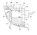
- Sectional drawing which shows the rolling bearing unit with a rotational speed detection apparatus of the 1st example of embodiment of this invention.
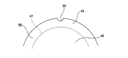
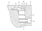
- the B section enlarged view of FIG. The figure which took out the fitting metal core in the rolling bearing unit with a rotational speed detection apparatus of FIG. 1, and looked at the circumferential direction part from the axial direction inner side.
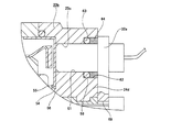
- the figure which shows the location corresponded to the C section of FIG. 1 of the rolling bearing unit with a rotational speed detection apparatus of the 2nd example of embodiment of this invention.
- the enlarged view of the location corresponded to the B section of Drawing 1 of the rolling bearing unit with a rotation speed detector of the 2nd example of an embodiment of the invention.
- the enlarged view of the location corresponded to the B section of FIG.
- the enlarged view of the location corresponded to the B section of Drawing 1 of the rolling bearing unit with a rotation speed detector of the 4th example of an embodiment of the invention.
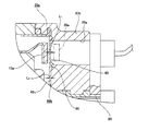
- the figure which shows the location corresponded to the C section of FIG. 1 of the rolling bearing unit with a rotational speed detection apparatus of the 5th example of embodiment of this invention.
- the A section enlarged view of FIG. The fragmentary sectional view of a metal mold
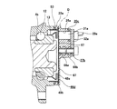
- FIG. 1 to 3 show a first example of an embodiment of the present invention.
- the feature of this example is that the structure of the cap 19a that closes the axially inner end opening of the outer ring 2 is devised. Since the configuration and operational effects of the other parts are basically the same as those of the above-described conventional structure, overlapping illustrations and explanations are omitted or simplified. The description will focus on the parts that were not explained.
- the rolling bearing unit 1a with a rotational speed detection device of this example supports a wheel that is a driven wheel rotatably with respect to a suspension device such as a knuckle and detects the rotational speed of the wheel.
- a hub 3 that is a rotating wheel is rotatably supported on a radially inner side of a certain outer ring 2 via a plurality of rolling elements 12 and 12.
- the hub body 6 constituting the outer ring 2 and the hub 3 is made of medium carbon steel such as S53C, and at least the surfaces of the tracks 4a, 4b, and 8a are subjected to hardening treatment such as induction hardening.
- the inner ring 7 and the respective rolling elements 12 and 12 constituting the hub 3 are made of high carbon chrome bearing steel such as SUJ2, and are subjected to a hardening process by, for example, quenching.
- the rolling elements 12 to be used are not limited to the balls as shown in FIG. When the rolling bearing unit with a rotational speed detection device 1a of this example is used for an automobile having a heavy weight, a tapered roller can be used as the rolling element 12.
- an encoder 13a is externally fitted and fixed (press-fit) to the axially inner end (right end in FIG. 1) of the outer peripheral surface of the inner ring 7.
- the encoder 13a includes a support ring 14a and an encoder body 16a.
- the support ring 14a is formed in an annular shape with a substantially L-shaped cross section by pressing a ferritic stainless steel plate such as SUS430 or a cold rolled steel plate such as SPCC subjected to rust prevention treatment. Has been.
- the support ring 14a is provided with a cylindrical fitting tube portion 42 and an outward direction that is bent in a radially outward direction from the axially outer end portion (left end portion in FIG. 1) of the fitting tube portion 42.
- the fitting tube portion 42 is provided in the outer half portion in the axial direction, and is provided on the inner half portion in the axial direction with a small diameter portion directly fitted on the inner end portion in the axial direction of the inner ring 7. And a taper portion that is inclined in a direction in which the outer diameter dimension increases as it goes to.
- the encoder body 16a is formed in a ring shape by a permanent magnet such as a rubber magnet or a plastic magnet mixed with a magnetic material such as ferrite powder.
- the encoder body 16a is magnetized in the axial direction and the direction of magnetization. These are changed alternately and at equal intervals in the circumferential direction.
- the inner surface in the axial direction (detected surface) of the encoder main body 16a is set in the axial direction of the hub main body 6. It is located axially inward from the axially inner end surface of the caulking portion 10 formed at the end.
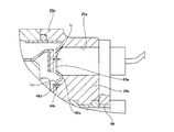
- the cap 19a attached to the inner end in the axial direction of the outer ring 2 includes a cap body 20a made of synthetic resin, a metal fitting core 44 disposed inside the cap body 20a, and the cap body. It is comprised from the nut 27a for attachment arrange
- the cap body 20a is made by, for example, injection molding a polyamide resin mixed material in which glass fiber is appropriately added to polyamide 66 resin. If an amorphous aromatic polyamide resin (modified polyamide 6T / 6I) and a low water-absorbing aliphatic polyamide resin (polyamide 11 resin, polyamide 12 resin, polyamide 610 resin, polyamide 612 resin) are appropriately added to the polyamide resin, the water resistance becomes higher.
- the cap body 20a manufactured in this way is formed in a bottomed cylindrical shape including a cap cylindrical portion 22a and a cap bottom portion 23a that closes an axially inner end opening of the cap cylindrical portion 22a.
- a concave groove 45 having a rectangular cross section that is open outward in the axial direction and inward in the radial direction is formed over the entire circumference on the inner peripheral surface of the outer end portion in the axial direction of the cap cylindrical portion 22a. Further, of the axial outer end surface of the cap cylindrical portion 22a, the outer diameter side portion from the axial outer end opening of the concave groove 45 abuts against the axial inner end surface of the outer ring 2, and thus a flat surface shape. Is formed.
- a mounting portion 24a bulging inward in the axial direction (having a larger axial thickness dimension) than the other portions is provided in a part of the cap bottom portion 23a in the circumferential direction.
- a through hole 25a penetrating in the axial direction is formed in a portion of the mounting portion 24a facing the detection surface of the encoder 13a (encoder main body 16a) in the assembled state.
- a holding hole 46 for holding the mounting nut 27a is provided inside the mounting portion 24a at a position shifted radially inward from the through hole 25a.
- Such a holding hole portion 46 has a bottomed cylindrical shape that is open at the inner end in the axial direction and closed at the outer end in the axial direction.
- the mounting nut 27a is insert-molded into the cap bottom portion 23a. Formed by things.
- the fitting core 44 is formed into a bottomed cylindrical shape (a petri dish with a substantially U-shaped cross section) by pressing a nonmagnetic metal plate such as an austenitic stainless steel plate or an aluminum alloy plate.
- a nonmagnetic metal plate such as an austenitic stainless steel plate or an aluminum alloy plate.
- Such a fitting metal core 44 includes a metal core cylindrical portion 47, a metal core bottom portion 48 that closes an axially inner end opening of the metal core cylindrical portion 47, and a flange that corresponds to a retaining mechanism according to the claims. Part 49.
- the flange portion 49 is formed in a state in which it is bent at a right angle radially outward from the inner end in the axial direction of the cored bar cylindrical portion 47 and an intermediate portion thereof is folded back 180 degrees radially inward.
- the radially inner end of the flange portion 49 is continuous with the radially outer end of the metal core bottom portion 48.
- the axially inner side surfaces of the flange portion 49 and the core metal bottom portion 48 are located on the same plane.
- the flange portion 49 can also be formed in a state of being inclined inward in the axial direction as it goes outward in the radial direction, for example, like a flange portion 49a shown in FIG.
- the flatness of the core metal bottom portion 48 can be improved by forming the core metal bottom portion 48 so as to be pulled outward in the radial direction. .
- non-rotating notches 50 and 50 constituting a detent structure according to the claims are provided on both side surfaces of the flange portion 49 in the axial direction. And it is formed in the state opened to the radial direction outer end edge.
- Each of the non-rotating cutouts 50 and 50 is formed by, for example, cutting a part of the flange portion 49 in the circumferential direction into a non-circular shape or bending (crushing) the inner side in the radial direction. .
- the fitting cored bar 44 having such a configuration is molded at the time of injection molding of the cap body 20a on the inner diameter side of the cap cylindrical part 22a of the cap body 20a and on the outer side in the axial direction of the cap bottom part 23a.
- the cap body 20a is fixed.
- the axially inner half portion of the cored bar cylindrical portion 47 is fixed to the inner diameter side of the cap cylindrical portion 22a in a state where the flange portion 49 is embedded in the cap cylindrical portion 22a.
- the outer half portion in the axial direction protrudes outward in the axial direction from the outer end surface in the axial direction of the cap cylindrical portion 22a.
- the core metal bottom portion 48 has an inner surface in the axial direction fixed to an outer surface in the axial direction of the cap bottom portion 23a. In this state, the axially outer end opening of the through hole 25a of the cap bottom 23a is blocked by a part of the axial inner surface of the core metal bottom 48 (one axial inner surface of the metal core bottom 48). Part is exposed in the through hole 25a).
- both side surfaces in the axial direction of the flange portion 49 and the cap main body 20a are engaged with each other in the axial direction, whereby the fitting core metal 44 and the cap main body 20a in the axial direction are engaged. Relative displacement is prevented. Further, the circumferentially opposite side surfaces of the respective rotation stop notches 50, 50 of the flange portion 49 and the portion of the cap body 20a filled inside the rotation stop notches 50, 50 are circumferential. By engaging in the direction, relative rotation between the fitting core metal 44 and the cap body 20a is prevented.
- the mounting nut 27a has a bottomed cylindrical shape in which a female thread portion 51 is formed on the inner peripheral surface, and a concave groove 52 is formed around the entire circumference of the axially intermediate portion of the outer peripheral surface. It is embedded in a portion corresponding to the holding hole 46 of 24a.
- the mounting nut 27a is embedded in the cap main body 20a, and both side surfaces in the axial direction of the concave groove 52 and the inner side of the concave groove 52 of the cap main body 20a are filled. Are engaged in the axial direction to prevent relative displacement of the mounting nut 27a in the axial direction with respect to the cap body 20a.
- the inner end surface in the axial direction of the mounting nut 27a is located on the same virtual plane as the inner side surface in the axial direction of the mounting portion 24a, and the female screw portion 51 opens on the inner side surface in the axial direction of the mounting portion 24a. ing.
- the axial outer end surface of the mounting nut 27a is axially more than the axial outer end surface of the cap bottom portion 23a. In the state located inside, it is embedded in the mounting portion 24a.
- the axially outer end surface of the mounting nut 27a may be positioned on the same imaginary plane as the axially outer end surface of the cap bottom 23a.
- the mounting nut 27a has a structure that does not penetrate in the axial direction (cap nut). For this reason, it is not necessary to screw with a male screw as shown in FIG. 14 at the time of insert molding, and the workability of insert molding can be improved.
- insert molding is performed in a state of being screwed with a male screw (see FIG. 14) so that the resin does not enter inside the mounting nut.
- the axial outer end opening of the mounting nut is formed on the axial inner side surface of the core metal bottom.
- the method of fixing the mounting nut 27a to the cap body 20a is not limited to insert molding, and a portion corresponding to the holding hole 46 of the cap body 20a has a bottomed cylindrical shape, and a shaft is formed on the inner peripheral surface thereof.
- a nut insertion hole having a long locking groove formed in the direction is formed, and a mounting nut having a long locking protrusion or the like in the axial direction on the outer peripheral surface is connected to the locking protrusion and the locking groove.
- the cap 19a having the above-described configuration has a mold insertion portion having an outer peripheral surface shape that matches the inner peripheral surface shape of the through-hole 25a, as shown in FIG.
- a device provided in a part of one of the mold 36 and the lower mold 37) is used, and the mounting nut 27a and the fitting core are placed in a cavity 38 defined between the two molds.
- the cap 19a having the above-described configuration is formed on the outer circumferential surface of the cored bar cylindrical portion 47 in a ring shape that overlaps with the concave groove 45 of the cap cylindrical portion 22a in the radial direction.
- the outer peripheral surface of the outer half of the axial direction of the fitting core metal 44 is the inner side in the axial direction of the outer ring 2.
- the axial outer end surface of the cap cylindrical portion 22a is abutted against the axial inner end surface of the outer ring 2 to be assembled to the outer ring 2.
- the outer surface in the axial direction of the metal core bottom 48 is in close proximity to the detected surface of the encoder 13a via a predetermined axial gap (air gap).
- the O-ring 53 is clamped in an axially compressed state between the axial side surface of the concave groove 45 and the axial inner end surface of the outer ring 2 in the assembled state as described above. Is done. For this reason, even when foreign matter such as water enters from the abutting portion between the axial outer end surface of the cap cylindrical portion 22a and the axial inner end surface of the outer ring 2, such foreign matter is caused by the O-ring 53. Thus, it is possible to effectively prevent the metal fitting portion between the outer peripheral surface of the cored bar cylindrical portion 47 and the inner peripheral surface of the outer ring 2 in the axial direction from being reached.
- the end of the coupling surface between the cap body 20a and the fitting core 44 (the boundary surface between the members 20a and 44) is the rolling elements 12 and 12 or the encoder. It does not exist in the space 18 in which 13a is installed. That is, the coupling surface is not provided in a state of being continuous (exposed) directly to the space 18. For this reason, for example, foreign matters such as water entering from a portion between the inner peripheral surface of the through hole 25a of the mounting portion 24a and the outer peripheral surface of the sensor holder 30a, which will be described later, are caused by the cap main body 20a and the fitting core. It does not penetrate into the space 18 through the gap generated on the bonding surface with the gold 44.
- the outer end portion in the axial direction of the coupling surface is located at the inner end portion in the radial direction of the side surface in the axial direction of the groove 45. For this reason, even if foreign matter such as water enters through the gap formed on the coupling surface between the cap main body 20a and the fitting core metal 44 up to the position, the foreign matter is caused by the O-ring 53. Intrusion into the space 18 can be prevented.
- the sensor unit 28a for detecting the rotational speed is supported and fixed to the cap 19a having the above-described configuration.
- the sensor unit 28a includes a sensor 29a and a sensor holder 30a.
- the sensor 29a has a magnetic detecting element such as a Hall element or a magnetoresistive element installed in the detecting section, and changes the output signal in response to a change in the characteristics of the detected surface of the encoder 13a.
- the sensor holder 30a is formed by injection molding a synthetic resin such as a polyamide resin.
- the sensor holder 30a holds the sensor 29a at the front end (axially outer end), and has an inner diameter dimension of the through hole 25a of the cap bottom 23a.
- the male thread portion 33 of the bolt 34 inserted through the through hole 69 formed in the mounting flange portion 32a in the state where the insertion portion 31a is directly inserted into the through hole 25a, The nut is fixed to the cap 19a (attachment portion 24a) by being screwed into the female screw portion 51 of the nut 27a.
- the distal end surface (axially outer end surface) of the insertion portion 31a and the axially inner side surface of the cored bar bottom 48 constituting the fitting cored bar 44 Is in the state of facing or abutting through a minute gap in the axial direction.
- the sensor 29a (the detection portion thereof) held at the distal end portion of the insertion portion 31a faces the detection surface of the encoder 13a via the cored bar bottom portion 48.
- the wheel fixed to the hub 3 can be rotatably supported with respect to the suspension device supporting the outer ring 2.
- the encoder 13a rotates together with the hub 3 as the wheel rotates, the detecting portion of the sensor 29a facing the detection surface of the encoder 13a via the cored bar bottom 48 of the fitting cored bar 44.
- N poles and S poles existing on the detected surface of the encoder 13a alternately pass in the vicinity of.
- the direction of the magnetic flux flowing in the magnetic detection element constituting the sensor 29a is alternately changed, and the characteristics of the magnetic detection element are alternately changed. Since the frequency at which the characteristics of the magnetic detection element change in this way is proportional to the rotational speed of the hub 3, the ABS and TCS can be appropriately controlled by sending the output signal of the sensor 29a to a controller (not shown).
- the sealing performance by the cap 19a can be sufficiently secured. That is, in the case of the present invention, the cap 19a is assembled with the cored bar cylindrical portion 47 of the fitting cored bar 44 fitted and fixed to the inner peripheral surface of the axially inner end of the outer ring 2. The inner side surface in the axial direction of the bottom portion 48 closes the axially outer end opening of the through hole 25a formed in the cap bottom portion 23a. For this reason, when foreign matters such as water enter the axial outer end (back) between the outer peripheral surface of the insertion portion 31a constituting the sensor holder 30a and the inner peripheral surface of the through hole 25a.
- a flange portion 49 is formed on the fitting metal core 44, and both side surfaces in the axial direction of the flange portion 49 are engaged with the cap body 20a in the axial direction. For this reason, the axial relative displacement of the fitting core 44 and the cap body 20a can be prevented. Further, the circumferentially opposite side surfaces of the rotation stopper notches 50, 50 of the flange portion 49 and the portions of the cap body 20a filled in the rotation stopper notches 50, 50 are circumferentially connected. Engage with respect to direction. For this reason, relative rotation between the fitting cored bar 44 and the cap body 20a can be prevented.
- the outer peripheral surface of the cored bar cylindrical portion 47 of the fitting cored bar 44 is directly fitted to the inner peripheral surface of the inner end portion in the axial direction of the outer ring 2. For this reason, even when the use is continued, it is possible to prevent a gap or the like from being generated in the fitting portion. That is, like the conventional structure described above, the fitting ring 21 (see FIG. 12) is fitted to the inner peripheral surface of the inner end portion in the axial direction of the outer ring 2 through the cap cylindrical portion 22 of the cap body 20 made of synthetic resin.
- the O-ring 53 is externally fitted to a portion of the outer peripheral surface of the cored bar cylindrical portion 47 that overlaps the concave groove 45 of the cap cylindrical portion 22a in the radial direction. For this reason, it penetrate
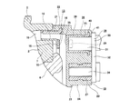
- FIG. 4 to 7 show a second example of the embodiment of the present invention.
- the cored bar bottom 48a constituting the fitting cored bar 44a faces the through hole 25a of the mounting part 24b in the assembled state in the radially intermediate part.
- Core metal through holes 54 and 54 penetrating through the core metal bottom portion 48a in the axial direction are formed at a plurality of locations in the circumferential direction (4 locations in the illustrated example) radially inward of the position.
- the core metal through holes 54 are arranged on the axially outer side of the axially outer surface of the core metal bottom part 48a.
- Cap engaging portions 55, 55 having a circumscribed circle diameter larger than those of the core metal through holes 54, 54 are provided in the peripheral portion of the core 54.
- Each of the cap engaging portions 55, 55 and the cap bottom portion 23b are continuous by cap continuous portions 56, 56 which are resin portions filled inside the core metal through holes 54, 54.
- the cap engaging portions 55 and 55 are not limited to a circular shape as shown in the figure, and various shapes can be adopted.
- the engagement core metal 44a and the cap main body 20b are engaged with each other in the circumferential direction between the inner side surfaces of the core metal through holes 54 and 54 and the cap continuous portions 56 and 56. Relative rotation is blocked. Further, the engagement core metal 44a and the cap main body 20b are engaged with each other in the axial direction between the axially outer side surface of the cored bar bottom portion 48a and the axially inner side surfaces of the cap engaging portions 55 and 55. Relative displacement in the axial direction is prevented.
- the configuration as described above prevents relative rotation and relative displacement in the axial direction between the fitting core metal 44a and the cap body 20b, so that the first example of the embodiment described above can be used.
- the flange portion 49 is not formed on the fitting mandrel 44. That is, in the case of this example, the outer end in the radial direction of the cored bar bottom 48a is bent at a right angle outward in the axial direction to form the cored bar cylindrical part 47a. For this reason, when the fitting cored bar 44a is manufactured by press working, the folding process for forming the flange portion 49 is not required, so that the processing cost can be reduced.
- the fitting core is made of an austenitic stainless steel sheet, due to martensitic transformation accompanying plastic deformation, the processed part becomes brittle or magnetized, and the folding process may be difficult.
- an inclined portion 59 that is inclined outward in the axial direction toward the outer side in the radial direction is provided near the radially outer end of the core metal bottom portion 48b.
- the cored bar cylindrical part 47b can also be formed by bending and bending the radially outer end of the inclined part 59 outward in the axial direction so as to be orthogonal to the cored bar bottom part 48b. In such a case, it is possible to further reduce the bending processing force when the fitting mandrel is made.
- a concave groove 57 is formed around the entire circumference of the outer peripheral surface of the insertion portion 31b constituting the sensor holder 30b at a portion near the outer end in the axial direction.
- a rubber O-ring 58 having a circular cross section is engaged with the concave groove 57.
- Such an O-ring 58 is formed between the inner peripheral surface of the through hole 25a and the bottom of the concave groove 57 in a state where the insertion part 31b of the sensor holder 30b is inserted into the through hole 25a of the mounting part 24b. Therefore, it is clamped in an elastically compressed state. In this manner, foreign matter such as water is prevented from entering between the inner peripheral surface of the through hole 25a and the outer peripheral surface of the insertion portion 31b in the axial direction outside the concave groove 57. I am trying.
- a concave groove 57 for locking the O-ring 58 is provided on the outer peripheral surface of the insertion portion 31b.
- the concave groove 60 is also possible to form the concave groove 60 on the inner peripheral surface of the through hole 25b of the mounting portion 24c. Since such a concave groove 60 cannot be formed by injection molding, it is formed by cutting or the like after making a cap by injection molding.
- the inner peripheral surface shape of the through-hole 25c of the mounting portion 24d is formed by replacing the small diameter portion 61 provided on the axially outer side and the large diameter portion 62 provided on the axially inner side with the stepped portion 63.
- the O-ring 58 is fitted into the outer end portion in the axial direction of the large-diameter portion 62, and the shaft of the large-diameter portion 62 is positioned more than the position where the O-ring 58 is fitted.
- a cylindrical plug member 64 made of synthetic resin or rubber is fitted into the inner portion in the direction. In this way, the O-ring 58 is prevented from being displaced in the axial direction inside the large diameter portion 62.
- the stopper member 64 is prevented from coming off by the outer surface in the axial direction of the mounting flange portion 32a constituting the sensor holder 30a.
- a flange portion 49 is formed on the fitting mandrel 44a, and the fitting mandrel 44a and the cap body 20b are formed. It is possible to further prevent relative rotation and relative displacement in the axial direction. About another structure and an effect, it is the same as that of the case of the 1st example of embodiment mentioned above.
- FIG. 8 shows a third example of the embodiment of the present invention.
- the sensor seat surface 65 is formed such that the thickness dimension L1 in the axial direction is smaller than the thickness dimension L2 of other portions (L1 ⁇ L2).
- the sensor seat surface 65 is formed of the through-hole in the fitting cored bar 44 (see FIG. 1) having a flat axial inner surface as in the first example of the above-described embodiment.
- a portion facing 25a is subjected to coining, and a part of the metal existing in the portion is moved to the periphery thereof. Further, in the case of this example, along with the formation of the sensor seat surface 65 by the coining process as described above, another portion of the inner surface in the axial direction of the cored bar bottom portion 48c is disposed around the sensor seat surface 65. An annular convex portion 66 that protrudes inward in the axial direction is formed.
- the sensor seat surface 65 is formed in a state before the fitting metal core 44b is molded on the cap body 20c by injection molding.
- the detection accuracy can be improved by reducing the distance in the axial direction between the detection unit of the sensor 29a and the detection surface of the encoder 13a.
- the annular convex portion 66 of the fitting metal core 44b and the portion of the cap main body 20c that exists around the annular convex portion 66 are in the circumferential direction of the cap main body 20c. Is engaged to prevent the fitting core bar 44b and the cap body 20c from rotating.
- this example can also be applied to a fitting metal core as in the second example of the embodiment described above. About another structure and an effect, it is the same as that of the case of the 1st example of embodiment mentioned above.
- FIG. 9 shows a fourth example of the embodiment of the present invention.
- the sensor seat surface 65a is formed in which the thickness dimension L1 in the axial direction is smaller than the thickness dimension L2 of other portions (L1 ⁇ L2).
- the sensor seating surface 65a is, for example, of the fitting cored bar 44a (see FIGS. 4A and 4B) having a flat axial inner surface, as shown in the second example of the embodiment described above.
- Bending is performed around the portion facing the through hole 25a, and the portion corresponding to the sensor seat surface 65a is extended. Further, in the case of this example, along with the formation of the sensor seat surface 65a by the bending process as described above, other portions of the inner surface in the axial direction of the cored bar bottom portion 48d around the sensor seat surface 65a. Further, an annular convex portion 66a having an arcuate cross section projecting inward in the axial direction is formed.
- the sensor seat surface 65a is formed in a state before the fitting core bar 44c is molded on the cap body 20c by injection molding.
- the shape of the convex portion formed by bending is not limited to an annular shape.
- bending is performed only on both sides in the radial direction around the portion corresponding to the sensor seat surface 65a.
- a straight convex portion may be formed by bending only on both sides in the circumferential direction.
- the portion corresponding to the sensor seat surface 65a is extended by forming the linear convex portion.
- the detection accuracy can be improved by reducing the distance in the axial direction between the detection unit of the sensor 29a and the detection surface of the encoder 13a.
- the annular convex portion 66a of the fitting metal core 44c and the portion of the cap body 20c existing around the annular convex portion 66a are in the circumferential direction of the cap main body 20c. Is engaged to prevent the fitting core bar 44b and the cap body 20c from rotating.
- this example can also be applied to a fitting metal core as in the second example of the embodiment described above. About another structure and an effect, it is the same as that of the case of the 1st example of embodiment mentioned above.
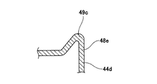
- [Fifth Example of Embodiment] 10 to 11 show a fifth example of the embodiment of the present invention.
- other portions are provided at a plurality of positions in the circumferential direction at the radially intermediate portion of the axially inner side surface of the cored bar bottom portion 48e constituting the fitting cored bar 44d.
- Engagement projections 67 and 67 having a circular arc cross section projecting further inward in the axial direction are formed.
- these engaging projections 67 and 67 are formed by, for example, pressing or the like before the fitting core bar 44d is molded on the cap body 20c by injection molding.
- the mounting nut 27b has a structure with both axial ends open.
- concave grooves 68a and 68b are formed over the entire circumference at two positions spaced apart in the axial direction on the outer peripheral surface of the mounting nut 27b.
- Such a mounting nut 27b is insert-molded in the cap body 20c with the axially outer end surface of the mounting nut 27b being in contact (closed) with the axially inner side surface of the core bottom part 48e. Embedded by. Therefore, in the case of this example, as in the case of using a mounting nut (cap nut) whose outer end (back) in the axial direction is closed, it is screwed with a male screw as shown in FIG. 14 at the time of insert molding. You do n’t have to. As a result, the workability of insert molding can be improved.
- each of the engaging projections 67 and 67 and a portion of the cap body 20c that exists around each of the engaging projections 67 and 67 are the caps.
- By engaging in the circumferential direction of the main body 20c relative rotation in the circumferential direction between the fitting cored bar 44d and the cap main body 20c is prevented.
- the engaging protrusions 67, 67 a structure in which an engaging recess (not shown) is formed on the inner surface in the axial direction of the metal core bottom portion 48e so as to be recessed outward in the axial direction from other portions. It can also be adopted.
- each of the engaging recesses and the portion of the cap body that is filled inside each of the engaging recesses engage with each other in the circumferential direction of the cap body, so that the fitting cored bar. And the relative displacement in the circumferential direction with the cap body can be prevented.
- the non-rotating cutouts 50 and 50 are not formed in the flange portion 49b of the fitting cored bar 44d as in the first example of the above-described embodiment. . If such a structure in which the rotation stop notch is not formed is employed, for example, a flange portion 49c shown in FIG. As a result, it is possible to reduce the processing force when forming the flange portion 49c. About another structure and an effect, it is the same as that of the case of the 1st example of embodiment mentioned above.
- the present invention can be implemented by appropriately combining the structures of the examples of the above-described embodiments.
Landscapes
- Engineering & Computer Science (AREA)
- General Engineering & Computer Science (AREA)
- Mechanical Engineering (AREA)
- Physics & Mathematics (AREA)
- General Physics & Mathematics (AREA)
- Sealing Of Bearings (AREA)
- Rolling Contact Bearings (AREA)
Priority Applications (3)
| Application Number | Priority Date | Filing Date | Title |
|---|---|---|---|
| CN201580011190.XA CN106062393B (zh) | 2014-02-28 | 2015-02-26 | 带转速检测装置的滚动轴承单元 |
| US15/121,828 US9784319B2 (en) | 2014-02-28 | 2015-02-26 | Rolling bearing unit with rotational speed detecting device |
| EP15754573.2A EP3112712B1 (en) | 2014-02-28 | 2015-02-26 | Rolling bearing unit with rotational velocity detection device |
Applications Claiming Priority (2)
| Application Number | Priority Date | Filing Date | Title |
|---|---|---|---|
| JP2014-038325 | 2014-02-28 | ||
| JP2014038325A JP6260348B2 (ja) | 2014-02-28 | 2014-02-28 | 回転速度検出装置付転がり軸受ユニット |
Publications (1)
| Publication Number | Publication Date |
|---|---|
| WO2015129827A1 true WO2015129827A1 (ja) | 2015-09-03 |
Family
ID=54009141
Family Applications (1)
| Application Number | Title | Priority Date | Filing Date |
|---|---|---|---|
| PCT/JP2015/055710 WO2015129827A1 (ja) | 2014-02-28 | 2015-02-26 | 回転速度検出装置付転がり軸受ユニット |
Country Status (5)
| Country | Link |
|---|---|
| US (1) | US9784319B2 (zh) |
| EP (1) | EP3112712B1 (zh) |
| JP (1) | JP6260348B2 (zh) |
| CN (1) | CN106062393B (zh) |
| WO (1) | WO2015129827A1 (zh) |
Families Citing this family (5)
| Publication number | Priority date | Publication date | Assignee | Title |
|---|---|---|---|---|
| CN107542753A (zh) * | 2016-06-23 | 2018-01-05 | 舍弗勒技术股份两合公司 | 用于安装abs的轮速传感器的轮毂轴承 |
| JP6848454B2 (ja) * | 2017-01-13 | 2021-03-24 | 日本精工株式会社 | 軸受キャップ及び転がり軸受装置 |
| JP6516077B1 (ja) * | 2017-06-26 | 2019-05-22 | 日本精工株式会社 | 車輪支持用転がり軸受ユニット |
| JP7044029B2 (ja) * | 2017-12-19 | 2022-03-30 | 中西金属工業株式会社 | センサホルダ部を有する保護カバー、及び前記保護カバーを備えた軸受装置 |
| KR102490076B1 (ko) * | 2018-10-05 | 2023-01-19 | 주식회사 일진글로벌 | 차량용 센싱 장치, 휠 베어링 조립체 및 차량용 센싱 장치의 제조방법 |
Citations (7)
| Publication number | Priority date | Publication date | Assignee | Title |
|---|---|---|---|---|
| JP2003013982A (ja) * | 2001-06-29 | 2003-01-15 | Nsk Ltd | エンコーダ付軸受ユニット |
| JP2004084848A (ja) * | 2002-08-28 | 2004-03-18 | Koyo Seiko Co Ltd | 転がり軸受装置 |
| JP2006308103A (ja) * | 2006-05-22 | 2006-11-09 | Nsk Ltd | 回転速度検出装置付転がり軸受ユニット |
| JP2009150436A (ja) * | 2007-12-19 | 2009-07-09 | Ntn Corp | 回転速度検出装置付き車輪用軸受装置 |
| JP2012106547A (ja) * | 2010-11-16 | 2012-06-07 | Ntn Corp | 回転速度検出装置付き車輪用軸受装置 |
| JP2013221549A (ja) * | 2012-04-13 | 2013-10-28 | Ntn Corp | 車輪用軸受装置 |
| DE102013215621A1 (de) * | 2012-08-14 | 2014-02-20 | Schaeffler Technologies AG & Co. KG | Sensoranordnung eines Radlagers |
Family Cites Families (15)
| Publication number | Priority date | Publication date | Assignee | Title |
|---|---|---|---|---|
| US5975761A (en) * | 1997-03-31 | 1999-11-02 | Nsk Ltd. | Rolling bearing unit with rotational speed sensor |
| JP4857485B2 (ja) * | 2001-04-25 | 2012-01-18 | 日本精工株式会社 | エンコーダ付車輪用回転支持装置 |
| JP2003200455A (ja) | 2002-01-10 | 2003-07-15 | Nsk Ltd | 樹脂製部品の成形方法及び車輪速度検出器付きハブ軸受装置 |
| JP3988557B2 (ja) * | 2002-07-17 | 2007-10-10 | 株式会社ジェイテクト | 転がり軸受装置 |
| DE602004021470D1 (de) * | 2003-02-07 | 2009-07-23 | Jtekt Corp | Wälzlagereinheit mit sensor |
| JP4318205B2 (ja) * | 2003-06-23 | 2009-08-19 | Ntn株式会社 | 車輪用転がり軸受およびそれを備えた半浮動式車輪用軸受装置 |
| JP2005043127A (ja) * | 2003-07-24 | 2005-02-17 | Ntn Corp | 車輪用軸受装置 |
| JP2005233234A (ja) * | 2004-02-17 | 2005-09-02 | Ntn Corp | 車輪用軸受装置 |
| JP2009133357A (ja) * | 2007-11-29 | 2009-06-18 | Ntn Corp | 車輪用軸受装置 |
| JP2011052755A (ja) * | 2009-09-02 | 2011-03-17 | Ntn Corp | 回転速度検出装置付き車輪用軸受装置 |
| WO2011034134A1 (ja) | 2009-09-17 | 2011-03-24 | Ntn株式会社 | 回転速度検出装置付き車輪用軸受装置 |
| JP5331640B2 (ja) * | 2009-10-05 | 2013-10-30 | Ntn株式会社 | 回転速度検出装置付き車輪用軸受装置 |
| JP2011242188A (ja) * | 2010-05-17 | 2011-12-01 | Ntn Corp | 回転速度検出装置付き車輪用軸受装置 |
| DE102013215620A1 (de) | 2012-08-14 | 2014-02-20 | Schaeffler Technologies AG & Co. KG | Sensoranordnung und Radlager |
| JP5623592B2 (ja) * | 2013-05-20 | 2014-11-12 | Ntn株式会社 | 回転速度検出装置付き車輪用軸受装置用のセンサキャップおよびこれを備えた回転速度検出装置付き車輪用軸受装置および回転速度検出装置付き車輪用軸受装置用のセンサキャップの製造方法 |
-
2014
- 2014-02-28 JP JP2014038325A patent/JP6260348B2/ja not_active Expired - Fee Related
-
2015
- 2015-02-26 EP EP15754573.2A patent/EP3112712B1/en not_active Not-in-force
- 2015-02-26 US US15/121,828 patent/US9784319B2/en not_active Expired - Fee Related
- 2015-02-26 CN CN201580011190.XA patent/CN106062393B/zh not_active Expired - Fee Related
- 2015-02-26 WO PCT/JP2015/055710 patent/WO2015129827A1/ja active Application Filing
Patent Citations (7)
| Publication number | Priority date | Publication date | Assignee | Title |
|---|---|---|---|---|
| JP2003013982A (ja) * | 2001-06-29 | 2003-01-15 | Nsk Ltd | エンコーダ付軸受ユニット |
| JP2004084848A (ja) * | 2002-08-28 | 2004-03-18 | Koyo Seiko Co Ltd | 転がり軸受装置 |
| JP2006308103A (ja) * | 2006-05-22 | 2006-11-09 | Nsk Ltd | 回転速度検出装置付転がり軸受ユニット |
| JP2009150436A (ja) * | 2007-12-19 | 2009-07-09 | Ntn Corp | 回転速度検出装置付き車輪用軸受装置 |
| JP2012106547A (ja) * | 2010-11-16 | 2012-06-07 | Ntn Corp | 回転速度検出装置付き車輪用軸受装置 |
| JP2013221549A (ja) * | 2012-04-13 | 2013-10-28 | Ntn Corp | 車輪用軸受装置 |
| DE102013215621A1 (de) * | 2012-08-14 | 2014-02-20 | Schaeffler Technologies AG & Co. KG | Sensoranordnung eines Radlagers |
Non-Patent Citations (1)
| Title |
|---|
| See also references of EP3112712A4 * |
Also Published As
| Publication number | Publication date |
|---|---|
| US9784319B2 (en) | 2017-10-10 |
| JP2015161389A (ja) | 2015-09-07 |
| EP3112712A1 (en) | 2017-01-04 |
| JP6260348B2 (ja) | 2018-01-17 |
| CN106062393A (zh) | 2016-10-26 |
| US20170108049A1 (en) | 2017-04-20 |
| EP3112712B1 (en) | 2018-09-12 |
| CN106062393B (zh) | 2019-04-16 |
| EP3112712A4 (en) | 2017-03-15 |
Similar Documents
| Publication | Publication Date | Title |
|---|---|---|
| JP6323046B2 (ja) | 回転速度検出装置付転がり軸受ユニット | |
| WO2015129827A1 (ja) | 回転速度検出装置付転がり軸受ユニット | |
| WO2011027781A1 (ja) | 回転速度検出装置付き車輪用軸受装置 | |
| WO2015056526A1 (ja) | エンコーダ付組み合わせシールリング及びエンコーダ付転がり軸受ユニット | |
| JP6256122B2 (ja) | 回転速度検出装置付転がり軸受ユニット | |
| JP6572776B2 (ja) | センサユニット付軸受キャップ及び転がり軸受ユニット | |
| JP6349954B2 (ja) | 回転速度検出装置付軸受ユニット | |
| JP5623592B2 (ja) | 回転速度検出装置付き車輪用軸受装置用のセンサキャップおよびこれを備えた回転速度検出装置付き車輪用軸受装置および回転速度検出装置付き車輪用軸受装置用のセンサキャップの製造方法 | |
| JP2015166612A (ja) | 回転速度検出装置付軸受ユニット | |
| JP6287455B2 (ja) | 回転速度検出装置付転がり軸受ユニット | |
| JP4742796B2 (ja) | 回転検出装置付転がり軸受ユニット | |
| JP6417701B2 (ja) | 回転速度検出装置付転がり軸受ユニット | |
| JP6555366B2 (ja) | センサ付転がり軸受ユニット | |
| JP2016130100A (ja) | 軸受キャップ及び転がり軸受ユニット | |
| JP6375982B2 (ja) | 軸受キャップ及び転がり軸受ユニット | |
| JP2017048892A (ja) | ハブユニット軸受 | |
| JP6394051B2 (ja) | 回転速度検出装置付転がり軸受ユニット | |
| JP2017203515A (ja) | エンコーダ付転がり軸受ユニット | |
| JP2016038012A (ja) | 回転速度検出装置付転がり軸受ユニット | |
| JP2017036752A (ja) | 回転速度検出装置付ハブユニット軸受 | |
| JP2009068597A (ja) | エンコーダ付車輪用軸受装置 | |
| JP5002992B2 (ja) | エンコーダ付転がり軸受 | |
| JP6627577B2 (ja) | 車輪支持用転がり軸受ユニット | |
| JP2015218795A (ja) | センサ付転がり軸受ユニット | |
| JP2023139836A (ja) | 従動輪用加締めハブユニット軸受 |
Legal Events
| Date | Code | Title | Description |
|---|---|---|---|
| 121 | Ep: the epo has been informed by wipo that ep was designated in this application |
Ref document number: 15754573 Country of ref document: EP Kind code of ref document: A1 |
|
| REEP | Request for entry into the european phase |
Ref document number: 2015754573 Country of ref document: EP |
|
| WWE | Wipo information: entry into national phase |
Ref document number: 15121828 Country of ref document: US Ref document number: 2015754573 Country of ref document: EP |
|
| NENP | Non-entry into the national phase |
Ref country code: DE |