EP3112712B1 - Rolling bearing unit with rotational velocity detection device - Google Patents
Rolling bearing unit with rotational velocity detection device Download PDFInfo
- Publication number
- EP3112712B1 EP3112712B1 EP15754573.2A EP15754573A EP3112712B1 EP 3112712 B1 EP3112712 B1 EP 3112712B1 EP 15754573 A EP15754573 A EP 15754573A EP 3112712 B1 EP3112712 B1 EP 3112712B1
- Authority
- EP
- European Patent Office
- Prior art keywords
- axially
- insert
- cap
- outer ring
- cap body
- Prior art date
- Legal status (The legal status is an assumption and is not a legal conclusion. Google has not performed a legal analysis and makes no representation as to the accuracy of the status listed.)
- Not-in-force
Links
Images


Classifications
-
- F—MECHANICAL ENGINEERING; LIGHTING; HEATING; WEAPONS; BLASTING
- F16—ENGINEERING ELEMENTS AND UNITS; GENERAL MEASURES FOR PRODUCING AND MAINTAINING EFFECTIVE FUNCTIONING OF MACHINES OR INSTALLATIONS; THERMAL INSULATION IN GENERAL
- F16C—SHAFTS; FLEXIBLE SHAFTS; ELEMENTS OR CRANKSHAFT MECHANISMS; ROTARY BODIES OTHER THAN GEARING ELEMENTS; BEARINGS
- F16C41/00—Other accessories, e.g. devices integrated in the bearing not relating to the bearing function as such
- F16C41/007—Encoders, e.g. parts with a plurality of alternating magnetic poles
-
- B—PERFORMING OPERATIONS; TRANSPORTING
- B60—VEHICLES IN GENERAL
- B60B—VEHICLE WHEELS; CASTORS; AXLES FOR WHEELS OR CASTORS; INCREASING WHEEL ADHESION
- B60B27/00—Hubs
- B60B27/0005—Hubs with ball bearings
-
- B—PERFORMING OPERATIONS; TRANSPORTING
- B60—VEHICLES IN GENERAL
- B60B—VEHICLE WHEELS; CASTORS; AXLES FOR WHEELS OR CASTORS; INCREASING WHEEL ADHESION
- B60B27/00—Hubs
- B60B27/0047—Hubs characterised by functional integration of other elements
- B60B27/0068—Hubs characterised by functional integration of other elements the element being a sensor
-
- B—PERFORMING OPERATIONS; TRANSPORTING
- B60—VEHICLES IN GENERAL
- B60B—VEHICLE WHEELS; CASTORS; AXLES FOR WHEELS OR CASTORS; INCREASING WHEEL ADHESION
- B60B27/00—Hubs
- B60B27/0073—Hubs characterised by sealing means
-
- B—PERFORMING OPERATIONS; TRANSPORTING
- B60—VEHICLES IN GENERAL
- B60B—VEHICLE WHEELS; CASTORS; AXLES FOR WHEELS OR CASTORS; INCREASING WHEEL ADHESION
- B60B27/00—Hubs
- B60B27/0094—Hubs one or more of the bearing races are formed by the hub
-
- F—MECHANICAL ENGINEERING; LIGHTING; HEATING; WEAPONS; BLASTING
- F16—ENGINEERING ELEMENTS AND UNITS; GENERAL MEASURES FOR PRODUCING AND MAINTAINING EFFECTIVE FUNCTIONING OF MACHINES OR INSTALLATIONS; THERMAL INSULATION IN GENERAL
- F16C—SHAFTS; FLEXIBLE SHAFTS; ELEMENTS OR CRANKSHAFT MECHANISMS; ROTARY BODIES OTHER THAN GEARING ELEMENTS; BEARINGS
- F16C19/00—Bearings with rolling contact, for exclusively rotary movement
- F16C19/02—Bearings with rolling contact, for exclusively rotary movement with bearing balls essentially of the same size in one or more circular rows
- F16C19/14—Bearings with rolling contact, for exclusively rotary movement with bearing balls essentially of the same size in one or more circular rows for both radial and axial load
- F16C19/18—Bearings with rolling contact, for exclusively rotary movement with bearing balls essentially of the same size in one or more circular rows for both radial and axial load with two or more rows of balls
- F16C19/181—Bearings with rolling contact, for exclusively rotary movement with bearing balls essentially of the same size in one or more circular rows for both radial and axial load with two or more rows of balls with angular contact
- F16C19/183—Bearings with rolling contact, for exclusively rotary movement with bearing balls essentially of the same size in one or more circular rows for both radial and axial load with two or more rows of balls with angular contact with two rows at opposite angles
- F16C19/184—Bearings with rolling contact, for exclusively rotary movement with bearing balls essentially of the same size in one or more circular rows for both radial and axial load with two or more rows of balls with angular contact with two rows at opposite angles in O-arrangement
- F16C19/186—Bearings with rolling contact, for exclusively rotary movement with bearing balls essentially of the same size in one or more circular rows for both radial and axial load with two or more rows of balls with angular contact with two rows at opposite angles in O-arrangement with three raceways provided integrally on parts other than race rings, e.g. third generation hubs
-
- F—MECHANICAL ENGINEERING; LIGHTING; HEATING; WEAPONS; BLASTING
- F16—ENGINEERING ELEMENTS AND UNITS; GENERAL MEASURES FOR PRODUCING AND MAINTAINING EFFECTIVE FUNCTIONING OF MACHINES OR INSTALLATIONS; THERMAL INSULATION IN GENERAL
- F16C—SHAFTS; FLEXIBLE SHAFTS; ELEMENTS OR CRANKSHAFT MECHANISMS; ROTARY BODIES OTHER THAN GEARING ELEMENTS; BEARINGS
- F16C33/00—Parts of bearings; Special methods for making bearings or parts thereof
- F16C33/72—Sealings
- F16C33/723—Shaft end sealing means, e.g. cup-shaped caps or covers
-
- F—MECHANICAL ENGINEERING; LIGHTING; HEATING; WEAPONS; BLASTING
- F16—ENGINEERING ELEMENTS AND UNITS; GENERAL MEASURES FOR PRODUCING AND MAINTAINING EFFECTIVE FUNCTIONING OF MACHINES OR INSTALLATIONS; THERMAL INSULATION IN GENERAL
- F16C—SHAFTS; FLEXIBLE SHAFTS; ELEMENTS OR CRANKSHAFT MECHANISMS; ROTARY BODIES OTHER THAN GEARING ELEMENTS; BEARINGS
- F16C33/00—Parts of bearings; Special methods for making bearings or parts thereof
- F16C33/72—Sealings
- F16C33/76—Sealings of ball or roller bearings
- F16C33/78—Sealings of ball or roller bearings with a diaphragm, disc, or ring, with or without resilient members
- F16C33/7816—Details of the sealing or parts thereof, e.g. geometry, material
- F16C33/783—Details of the sealing or parts thereof, e.g. geometry, material of the mounting region
-
- F—MECHANICAL ENGINEERING; LIGHTING; HEATING; WEAPONS; BLASTING
- F16—ENGINEERING ELEMENTS AND UNITS; GENERAL MEASURES FOR PRODUCING AND MAINTAINING EFFECTIVE FUNCTIONING OF MACHINES OR INSTALLATIONS; THERMAL INSULATION IN GENERAL
- F16C—SHAFTS; FLEXIBLE SHAFTS; ELEMENTS OR CRANKSHAFT MECHANISMS; ROTARY BODIES OTHER THAN GEARING ELEMENTS; BEARINGS
- F16C35/00—Rigid support of bearing units; Housings, e.g. caps, covers
-
- G—PHYSICS
- G01—MEASURING; TESTING
- G01P—MEASURING LINEAR OR ANGULAR SPEED, ACCELERATION, DECELERATION, OR SHOCK; INDICATING PRESENCE, ABSENCE, OR DIRECTION, OF MOVEMENT
- G01P3/00—Measuring linear or angular speed; Measuring differences of linear or angular speeds
- G01P3/42—Devices characterised by the use of electric or magnetic means
- G01P3/44—Devices characterised by the use of electric or magnetic means for measuring angular speed
- G01P3/443—Devices characterised by the use of electric or magnetic means for measuring angular speed mounted in bearings
-
- B—PERFORMING OPERATIONS; TRANSPORTING
- B60—VEHICLES IN GENERAL
- B60B—VEHICLE WHEELS; CASTORS; AXLES FOR WHEELS OR CASTORS; INCREASING WHEEL ADHESION
- B60B27/00—Hubs
- B60B27/06—Hubs adapted to be fixed on axle
- B60B27/065—Hubs adapted to be fixed on axle characterised by the fixation of the hub to the axle
-
- F—MECHANICAL ENGINEERING; LIGHTING; HEATING; WEAPONS; BLASTING
- F16—ENGINEERING ELEMENTS AND UNITS; GENERAL MEASURES FOR PRODUCING AND MAINTAINING EFFECTIVE FUNCTIONING OF MACHINES OR INSTALLATIONS; THERMAL INSULATION IN GENERAL
- F16C—SHAFTS; FLEXIBLE SHAFTS; ELEMENTS OR CRANKSHAFT MECHANISMS; ROTARY BODIES OTHER THAN GEARING ELEMENTS; BEARINGS
- F16C2233/00—Monitoring condition, e.g. temperature, load, vibration
-
- F—MECHANICAL ENGINEERING; LIGHTING; HEATING; WEAPONS; BLASTING
- F16—ENGINEERING ELEMENTS AND UNITS; GENERAL MEASURES FOR PRODUCING AND MAINTAINING EFFECTIVE FUNCTIONING OF MACHINES OR INSTALLATIONS; THERMAL INSULATION IN GENERAL
- F16C—SHAFTS; FLEXIBLE SHAFTS; ELEMENTS OR CRANKSHAFT MECHANISMS; ROTARY BODIES OTHER THAN GEARING ELEMENTS; BEARINGS
- F16C2326/00—Articles relating to transporting
- F16C2326/01—Parts of vehicles in general
- F16C2326/02—Wheel hubs or castors
Definitions
- the present invention relates to an improvement to a rolling bearing unit with a rotational speed detecting device, which is used for rotatably supporting a wheel (a non-driven wheel) of a vehicle on a suspension and for detecting a rotational speed of this wheel.
- a rolling bearing unit is used to rotatably support a wheel of a vehicle on a suspension.
- ABS Anti-lock Braking System
- TCS Traction Control System
- rotatably supporting the wheel on the suspension and detecting the rotational speed of this wheel using a rolling bearing unit with a rotational speed detecting device in which the rotational speed detecting device is incorporated into the rolling bearing unit have recently been widely adopted.
- the rolling bearing unit 1 with the rotational speed detecting device having this conventional structure rotatably supports a hub 3 which is a rotatable ring at an inner diameter side of an outer ring 2 which is a stationary ring.
- the outer ring 2 include double rows of outer ring raceways 4a, 4b on an inner circumferential surface thereof, and a stationary-side flange 5 on an outer circumferential surface thereof.
- the outer ring 2 is supported by a knuckle (not shown) constituting the suspension and is not rotatable when used.
- the hub 3 is formed by combining a hub body 6 and an inner ring 7 and includes double rows of inner ring raceways 8a, 8b on an outer circumferential surface thereof.
- the hub 3 is supported at the inner diameter side of the outer ring 2 in the same center as this outer ring 2.
- the inner ring raceway 8a of an axially outboard row is directly formed at an axially middle portion of an outer circumferential surface of the hub body 6, and similarly the inner ring 7, on an outer circumferential surface of which the inner ring raceway 8b of an axially inboard row is formed is fitted around and fixed to a small diameter step part 9 formed at an axially inboard end side portion (where the axially inboard side refers to a center side of a vehicle body in a width direction in a state assembled to the suspension, whereas the axially outboard side refers to an outboard side of the vehicle body in the width direction.
- the axially inboard side refers to a center side of a vehicle body in a width direction in a state assembled to the suspension
- the axially outboard side refers to an outboard side of the vehicle body in the width direction.
- An axially inboard end face of the inner ring 7 is pressed by a caulking part 10 formed by plastically deforming an axially inboard end of the hub body 6 radially outward.
- a rotation-side flange 11 for supporting the wheel at an axially outboard end of the hub body 6 is provided at a portion which protrudes axially outward with respect to an axially outboard end opening of the outer ring 2.
- a plurality of rolling elements 12, 12 are provided between the outer ring raceways 4a, 4b and the inner ring raceways 8a, 8b, respectively, and the hub 3 is rotatably supported on the inner diameter side of the outer ring 2.
- An encoder 13 is fitted around and fixed to a portion deviating from the axially inboard ring raceway 8b inward at an axially inboard end of an outer circumferential surface of the inner ring 7.
- This encoder 13 is formed by combining a support ring 14, which is formed of a magnetic metal plate in an approximate L-shaped cross section and is of an annular shape as a whole, and an encoder body 16 which is attached to a side surface of a circular ring part 15 constituting this support ring 14.
- this encoder body 16 is formed of a permanent magnet such as a rubber magnet into which ferrite powder is mixed and is of a circular ring shape as a whole, it is magnetized in the axial direction, and changes directions of magnetization in an alternate manner at regular intervals in a circumferential direction. Therefore, S and N poles are disposed on an axially inboard surface or a detected surface of the encoder body 16 in an alternate manner at regular intervals.
- a seal ring 17 is installed between the axially outboard end opening of the outer ring 2 and the outer circumferential surface of the axially middle portion of the hub body 6, and a cap 19 is mounted on an axially inboard end opening of the outer ring 2.
- the cap 19 includes a bottomed cylindrical cap body 20 made by injection-molding a synthetic resin and a fitting ring 21 which is formed in an L-shaped cross section by stamping a non-magnetic metal plate and is of an annular shape as a whole.
- the cap body 20 includes a cap cylindrical part 22 and a cap bottom part 23 which closes an axially inboard end opening of the cap cylindrical part 22.
- the fitting ring 21 is fixed (molded) to an inner diameter side portion of a tip of the cap cylindrical part 22.
- a mount part 24 expanded axially inward (increased in an axial thickness dimension) compared to the other portion is provided at a radially outer side portion of the cap bottom part 23.
- a portion of the mount part 24 which axially faces the detected surface of the encoder 13 (the encoder body 16) is formed with a through-hole 25 which axially penetrates therethrough.
- a bottomed cylindrical sensor insertion cup 26 made of a non-magnetic stainless steel plate is molded into the through-hole 25. This sensor insertion cup 26 is buried in the mount part 24 by insert-molding at the injection molding of the cap body 20. Further, a mounting nut 27, on an inner circumferential surface of which internal threads are formed, is also buried in a portion of the mount part 24 which deviates from the through-hole 25 by insert-molding.
- a sensor unit 28 for detecting a rotational speed is supported and fixed to the cap 19.
- the sensor unit 28 includes a sensor 29 and a sensor holder 30. Since a magnetism detecting element such as a Hall element, a magnetic resistance element, or the like is provided for a detector, the sensor 29 changes an output signal in response to a change in characteristics of the detected surface of the encoder 13.
- the sensor holder 30 is formed by injection-molding a synthetic resin and includes an insertion part 31 for holding the sensor 29 and a mounting flange part 32 for fixing the cap 19.
- This sensor unit 28 is fixed to the cap 19 (the mount part 24) by screwing an external thread part of a bolt 34, which is inserted into a through-hole formed in the mounting flange part 32, onto an internal thread part of the mounting nut 27 in a state where the insertion part 31 is inserted to the sensor insertion cup 26.
- the wheel fixed to the hub 3 can be rotatably supported with respect to the suspension supporting the outer ring 2.
- the N and S poles which are present on the detected surface of the encoder 13 alternately pass through the vicinity of a detection part of the sensor 29 facing the detected surface of the encoder 13 via a bottom plate part 35 of the sensor insertion cup 26.
- a direction of magnetic flux flowing in the magnetism detecting element constituting the sensor 29 is alternately changed, and a characteristic of this magnetism detecting element is alternately changed.
- a frequency at which the characteristic of the magnetism detecting element is changed is proportional to the rotational speed of the hub 3.
- the ABS or the TCS can be suitably controlled.
- the space 18 in which the encoder 13 is installed can be sealed by the cap 19 (and the sensor insertion cup 26), it is possible to effectively prevent foreign materials from sticking to this encoder 13.
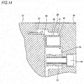
- a set of upper and lower molding dies 36, 37 as shown in, for instance, Fig. 14 is used to manufacture the cap 19.
- a molten synthetic resin is fed into a cavity 38 which is defined with these upper and lower molding dies 36, 37 brought into axially contact with each other and has a shape matched with an outer surface shape of the cap 19.
- the synthetic resin is fed with the sensor insertion cup 26 set in this cavity 38 (insert molding is performed).
- the bottom plate part 35 constituting this sensor insertion cup 26 is brought into contact with a part of the lower molding die 37 in order to regulate a position at which the sensor insertion cup 26 is installed, and similarly a part of the upper molding die 36 is butted against (bitten into) an axially inboard surface (curved surface) of a bent part 41 which is a connecting part between a cylindrical part 39 and a flange part 40 which constitute the sensor insertion cup 26.
- the cylindrical part 39 of this sensor insertion cup 26 may be elastically deformed (expanded) radially outward based on a pressing force for the sensor insertion cup 26 of the upper molding die 36.
- Injection molding is performed in this state, and thereafter, when the cap 19 is extracted from the cavity 38 (when the pressing force caused by the upper molding die 36 is removed), since the cylindrical part 39 is elastically restored (reduced in its diameter), there is a possibility of a gap occurring at a coupling surface between the outer circumferential surface of the cylindrical part 39 and a portion of the synthetic resin which is present around this cylindrical part 39.
- a foreign material such as water is invaded into this gap, there is a possibility that this foreign material further progresses axially outward to enter from an axially inboard end of the coupling surface to the space 18.
- Patent document 2 shows a further example of a rolling bearing unit with a rotational speed detectin device.
- the present invention has been made in view of the above circumstances and provides a rolling bearing unit with a rotational speed detecting device capable of sufficiently securing sealing performance by a cap.
- a rolling bearing unit with a rotational speed detecting device of the present invention is used to rotatably support a wheel for a non-driven wheel on a suspension such as a knuckle and includes an outer ring, a hub, a plurality of rolling elements, an encoder, a cap, and a sensor unit according to claim 1.
- an axial thickness dimension of a portion of the insert bottom part of the fitting insert, which axially faces the through-hole is smaller than a thickness dimension of a remaining portion of the insert bottom part other than the portion.
- a seal member is provided at a portion between an inner circumferential surface of the through-hole and an outer circumferential surface of the sensor holding part.
- the mounting nut has a tubular shape, both ends of which are axially open.
- An axially inboard end opening of the mounting nut is open to an axially inboard surface of the cap bottom part, and the mounting nut is disposed in a state where an axially outboard end opening thereof is closed by the insert bottom part.
- an anti-rotation structure for prohibiting relative rotation between the fitting insert and the cap body by engagement between the fitting insert and the cap body in a circumferential direction is provided between the fitting insert and the cap body.
- a retaining mechanism for prohibiting axial relative displacement between the fitting insert and the cap body by axial engagement between the fitting insert and the cap body is provided between the fitting insert and the cap body.
- the insert cylindrical part is directly fitted into the axially inboard end of the outer ring.
- a concave groove which is open to an axially outboard side and a radially inner side, is formed throughout an inner circumferential surface of an axially outboard end of the cap cylindrical part.
- an annular seal member is fitted around a portion, which radially overlaps the concave groove, of the outer circumferential surface of the insert cylindrical part, and is axially sandwiched between the axially inboard end face of the outer ring and an axial side surface of the concave groove.
- sealing performance by the cap can be sufficiently secured.
- the cap in the state where the cap is mounted on the axially inboard end of the outer ring by the insert cylindrical part of the fitting insert, the cap closes the axially outboard end opening of the through-hole formed in the cap bottom part. Therefore, even when a foreign material such as water is invaded into an axially outboard end of the portion between the outer circumferential surface of the sensor holder and the inner circumferential surface of the through-hole, this foreign material can be prohibited from being invaded into the space in which the rolling elements or the encoder is installed by the axially inboard surface of the insert bottom part.
- the axial thickness dimension of the portion of the insert bottom part of the fitting insert, which axially faces the through-hole, is smaller than the thickness dimension of the remaining portion of the insert bottom part other than the portion. Therefore, even when a thickness dimension of the metal plate forming this fitting insert is increased to secure rigidity of the fitting insert, detection accuracy of the sensor is improved by reducing the axial distance between the sensor held in the sensor holder and the encoder.
- the seal member is provided at the portion between the inner circumferential surface of the through-hole of the cap body and the outer circumferential surface of the sensor holder. Therefore, a foreign material such as water is effectively prevented from being invaded into the relevant portion. As a result, the water invaded into the relevant portion is prevented from being frozen and expanded to damage the sensor, or a gap is prevented from occurring at a coupled part between the fitting insert and the cap body.
- the mounting nut has the tabular shape, both ends of which are axially open. Therefore, in comparison with a mounting nut having a structure in which one axial end thereof is closed, an internal thread part can be easily machined by, for instance, rolling, and a manufacturing cost is reduced. In a state where the mounting nut is molded in the cap bottom part, the axially outboard end opening of the mounting nut is closed by the fitting bottom part.
- the anti-rotation mechanism or the retaining mechanism is provided between the fitting insert and the cap body. Therefore, a coupling and fixing force between the fitting insert and the cap body can be made strong.
- the insert cylindrical part is directly fitted into the axially inboard end of the outer ring. Therefore, like when this insert cylindrical part is fitted into the axially inboard end of the outer ring via the cap cylindrical part of the cap body made of a synthetic resin, the cap cylindrical part is unlikely to be deformed in use, and no gap is likely to occur between the inner circumferential surface of the outer ring and the outer circumferential surface of the cap cylindrical part.
- annular seal member is fitted around a portion of the outer circumferential surface of the insert cylindrical part, which radially overlaps the concave groove in the outer circumferential surface of the axially outboard end of the insert cylindrical part is formed, a foreign material such as water can be effectively prevented from being invaded into the fitting portion between the outer circumferential surface of the insert cylindrical part and the inner circumferential surface of the axially inboard end of the outer ring.
- Figs. 1 to 3 show a first example of an embodiment of the present invention.
- a feature of this example is that a structure of a cap 19a for closing an axially inboard end opening of an outer ring 2 is devised. Since structures and operational effects of other portions are basically the same as in the above-described conventional structure, overlapping illustration and description will be omitted or simplified. The following description is based on characteristic portions of this example and the portions which are not described previously.
- a rolling bearing unit 1a with a rotational speed detecting device of this example rotatably supports a wheel which is a non-driven wheel on a suspension such as a knuckle, detects a rotational speed of this wheel, and rotatably supports a hub 3 which is a rotatable ring at an inner diameter side of the outer ring 2 which is a stationary ring via a plurality of rolling elements 12, 12.
- the outer ring 2 and a hub body 6 constituting the hub 3 are made of medium-carbon steel such as S53C, and a hardening treatment such as high-frequency hardening is performed at least on surfaces of raceways 4a, 4b, 8a.
- an inner ring 7 constituting the hub 3 and each of the rolling elements 12, 12 are made of high carbon-chromium bearing steel such as SUJ2, and is subjected to a hardening treatment caused by, for instance, through quenching.
- the rolling elements 12 are not limited to balls as shown in Fig. 1 . When the rolling bearing unit 1a with the rotational speed detecting device of this example is used for a heavy vehicle, tapered rollers may be used as the rolling elements 12.
- An encoder 13a is fitted around and fixed to (press-fitted into and fixed to) an axially inboard end (a right end of Fig. 1 ) of an outer circumferential surface of the inner ring 7.
- This encoder 13a includes a support ring 14a and an encoder body 16a.
- the support ring 14a is formed in an approximately L-shaped cross section in an annular shape as a whole by stamping ferritic stainless steel plate such as SUS430 or a cold rolled steel plate such as SPCC on which a rust prevention treatment is performed.
- the support ring 14a includes a tubular fitting cylinder part 42, an outward flange part 43 provided in a state it is bent radially outward from an axially outboard end (a left end of Fig.
- the fitting cylinder part 42 is provided with a small diameter part which is provided at an axially outboard half part and is directly fitted around the axially inboard end of the inner ring 7, and a tapered part which is provided at an axially inboard half part and is inclined in a direction in which an outer diameter dimension is increased toward the axially inboard side.
- an axial position of the support ring 14a is regulated such that an axially inboard surface of the circular ring part 15a and an axially inboard end face of the outer ring 2 are located on the same virtual plane. Since the whole of the encoder body 16a is formed in a circular ring shape by a rubber magnet in which a magnetic material such as ferrite powder is mixed or a permanent magnet such as a plastic magnet, the encoder body 16a is magnetized in the axial direction, and a direction of the magnetization is changed in an alternate manner at regular intervals in a circumferential direction.
- an axially inboard surface (a detected surface) of this encoder body 16a is located at the axially inboard side with respect to an axially inboard end face of a caulking part 10 formed at an axially inboard end of the hub body 6.
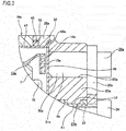
- the cap 19a mounted on an axially inboard end of the outer ring 2 includes a cap body 20a made of a synthetic resin, a fitting insert 44 which is disposed inside this cap body 20a and is made of a metal, and a mounting nut 27a disposed (inserted) in this cap body 20a.
- the cap body 20a is made, for example, by injection-molding a polyamide resin mixture material in which fiberglass is adequately added to a polyamide 66 resin. If an amorphous aromatic polyamide resin (modified polyamide 6T/6I) and a low water-absorbing aliphatic polyamide resin (a polyamide 11 resin, a polyamide 12 resin, a polyamide 610 resin, or a polyamide 612 resin) are adequately added to a polyamide resin, water resistance can be further improved.
- amorphous aromatic polyamide resin modified polyamide 6T/6I
- a low water-absorbing aliphatic polyamide resin a polyamide 11 resin, a polyamide 12 resin, a polyamide 610 resin, or a polyamide 612 resin
- the cap body 20a made in this way is formed in the shape of a bottomed cylinder including a cap cylindrical part 22a and a cap bottom part 23a closing an axially inboard end opening of this cap cylindrical part 22a.
- a concave groove 45 which has a rectangular cross section and is open to the axially outboard side and the radially inner side, is formed throughout an inner circumferential surface of an axially outboard end of the cap cylindrical part 22a.
- An outer diameter side portion from an axially outboard end opening of the concave groove 45 of an axially outboard end face of the cap cylindrical part 22a is formed in a flat surface shape to abut against the axially inboard end face of the outer ring 2.
- a portion of the cap bottom part 23a in a circumferential direction is provided with a mount part 24a which is expanded axially inward with respect to the other portion (or whose axial thickness dimension is increased).
- a portion of the mount part 24a which axially faces the detected surface of the encoder 13a (the encoder body 16a) in an assembled state is formed with a through-hole 25a which axially penetrates therethrough.
- a holding hole part 46 for holding the mounting nut 27a at an inner side thereof is provided at a position of the mount part 24a which is shifted from the through-hole 25a to the radially inner side.
- This holding hole part 46 has the shape of a bottomed cylinder in which an axially inboard end thereof is open and an axially outboard end is closed, and is formed by insert-molding the mounting nut 27a in the cap bottom part 23a as will be described below.
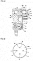
- the fitting insert 44 is formed in a bottomed cylindrical shape (in cross-sectional shape having an approximately C-shaped petri dish shape) by stamping a non-magnetic metal plate such as an austenitic stainless steel plate or aluminum based alloy plate.
- This fitting insert 44 includes an insert cylindrical part 47, an insert bottom part 48 which closes an axially inboard end opening of this insert cylindrical part 47, and a flange part 49 which corresponds to a retaining mechanism of the claims.
- This flange part 49 is formed in a state where it is bent radially outward from an axially inboard end of the insert cylindrical part 47 at right angles and its middle portion is folded back 180° radially inward.
- a radially inner end of the flange part 49 is continuous with a radially outer end of the insert bottom part 48.
- axially inboard surfaces of the flange part 49 and the insert bottom part 48 are mutually located on the same plane.
- the flange part 49 may be formed, for instance, in a state where it is inclined axially inward toward the radially outer side like a flange part 49a shown in Fig. 3 .
- Anti-rotation notches 50, 50 which constitute an anti-rotation structure of the claims are formed at a plurality of circumferential places of a radially outer edge of the flange part 49 in a state where they are open to axially inboard and outer sides of the flange part 49 and to the radially outer edge of the flange part 49.
- Each of the anti-rotation notches 50, 50 is formed by cutting or a part of the flange part 49 in the circumferential direction in a non-circular shape or bending (crushing) the part radially inward.
- the fitting insert 44 having this configuration is molded at an inner diameter side of the cap cylindrical part 22a of the cap body 20a and at an axially outboard side of the cap bottom part 23a at injection molding of the cap body 20a, and thereby is fixed to this cap body 20a.
- an axially inboard half part of the insert cylindrical part 47 is fixed to the inner diameter side of the cap cylindrical part 22a with the flange part 49 buried in the cap cylindrical part 22a, and similarly an axially outboard half part of the insert cylindrical part 47 protrudes axially outward with respect to the axially outboard end face of this cap cylindrical part 22a.
- An axially inboard surface of the insert bottom part 48 is fixed to an axially outboard surface of the cap bottom part 23a.
- the mounting nut 27a has the shape of a bottomed cylinder, on an inner circumferential surface of which an internal thread part 51 is formed and in an outer circumferential surface of which a concave groove 52 is formed throughout the circumference of an axially middle part, and is buried in a portion corresponding to the holding hole part 46 of the mount part 24a.
- An axially inboard end face of the mounting nut 27a is located on the same virtual plane as an axially inboard surface of the mount part 24a, and the internal thread part 51 is open to the axially inboard surface of the mount part 24a.
- an axial dimension of the mounting nut 27a is shorter than an axial dimension of the mount part 24a, an axially outboard end face of the mounting nut 27a is buried in the mount part 24a in a state where it is located inside in the axial direction with respect to an axially outboard end face of the cap bottom part 23a.
- the axially outboard end face of the mounting nut 27a may be located on the same virtual plane as the axially outboard end face of the cap bottom part 23a.
- the mounting nut 27a has a structure (a cap nut) in which it is not penetrated in the axial direction. For this reason, the mounting nut 27a does not need to be screwed on the external threads as shown in Fig. 14 at the insert molding, and workability of the insert molding can be improved.
- insert molding is performed in a state where the mounting nut is screwed on external threads (see Fig. 14 ) such that no resin is thrust into this mounting nut.
- a method of fixing the mounting nut 27a to the cap body 20a is not limited to the insert molding.
- a nut insertion hole which has a bottomed cylindrical shape and in an inner circumferential surface of which a locking concave groove which is long in the axial direction is formed, may be formed in a portion of the cap body 20a which corresponds to the holding hole part 46, and a mounting nut, on an outer circumferential surface of which a locking convex ridge which is long in the axial direction, or the like is provided, may be pressed into the nut insertion hole in a state where phases of the locking convex ridge and the locking concave groove are aligned.
- a nut on an outer circumferential surface of which convex ridges such as serration which are long in the axial direction are formed, may be pressed into a nut insertion hole, which is formed in the shape of a bottomed cylinder, in an inner circumferential surface of which concave grooves or the like are not formed, and the nut may be locked by forming the concave grooves in the inner circumferential surface of the nut insertion hole according to the convex ridges.
- the cap 19a having the configuration as described above can be formed by injection molding (axial draw molding) using a device provided with a molding die insertion part, which has an outer circumferential surface shape matched with the inner circumferential surface shape of the through-hole 25a, for a part of one of the pair of molding dies (the upper molding die 36 and the lower molding die 37) as shown in Fig. 14 in a state where the mounting nut 27a and the fitting insert 44 are disposed in the cavity 38 defined between these molding dies.
- the cap 19a having the configuration as described above is assembled to the outer ring 2 by directly fitting (metal fitting) the outer circumferential surface of the axially outboard half part of the fitting insert 44 into the inner circumferential surface of the axially inboard end of the outer ring 2 and by abutting the axially outboard end face of the cap cylindrical part 22a against the axially inboard end face of the outer ring 2 in a state where a O-ring 53, which is formed of a rubber in a circular cross-sectional shape and which corresponds to an annular seal member in the claims, is mounted on (fitted around) a portion which radially overlaps the concave groove 45 of the cap cylindrical part 22a out of the outer circumferential surface of the insert cylindrical part 47.
- the axially outboard surface of the insert bottom part 48 closely faces the detected surface of the encoder 13a via a predetermined axial gap (an air gap).
- the O-ring 53 is sandwiched between an axial side surface of the concave groove 45 and the axially inboard end face of the outer ring 2 in a state where it is axially compressed. For this reason, even when a foreign material such as water is invaded from a abutting part between the axially outboard end face of the cap cylindrical part 22a and the axially inboard end face of the outer ring 2, this foreign material is effectively prevented from reaching a metal fitting part between the outer circumferential surface of the insert cylindrical part 47 and the inner circumferential surface of the axially inboard end of the outer ring 2 due to the O-ring 53.
- an end of a coupling surface between the cap body 20a and the fitting insert 44 of the cap 19a is not present in the space 18 in which the rolling elements 12, 12 or the encoder 13a is installed. That is, the coupling surface is not provided in a state where it is directly continuous with (exposed to) this space 18. For this reason, for example, a foreign material such as water invaded from a portion or the like between the inner circumferential surface of the through-hole 25a of the mount part 24a and an outer circumferential surface of a sensor holder 30a (to be described below) is not invaded into the space 18 along a gap occurring at the coupling surface between the cap body 20a and the fitting insert 44.
- an axially outboard end of the coupling surface is located at a radially inner end of the axial side surface of the concave groove 45.
- a sensor unit 28a for detecting a rotational speed is supported and fixed to the cap 19a having the configuration as described above.
- This sensor unit 28a includes a sensor 29a and a sensor holder 30a. Since the sensor 29a installs therein a magnetism detecting element such as a Hall element, a magnetic resistance element, or the like on a detector, the sensor 29a changes an output signal in response to a change in characteristics of the detected surface of the encoder 13a.
- the sensor holder 30a Since the sensor holder 30a is formed by injection-molding a synthetic resin such as a polyamide resin, the sensor holder 30a includes an insertion part 31a which holds the sensor 29a at a tip thereof (an axially outboard end thereof), has an outer diameter dimension equal to or slightly smaller than an inner diameter dimension of the through-hole 25a of the cap bottom part 23a, corresponds to a sensor holding part in the claims, and has an approximately column shape (a rod shape), and a mounting flange part 32a which is provided at a base end of this insertion part 31a and is intended to be fixed to the cap 19a.
- a synthetic resin such as a polyamide resin
- This sensor unit 28a is fixed to the cap 19a (the mount part 24a) by screwing an external thread part 33 of a bolt 34, which is inserted into a through-hole 69 formed in the mounting flange part 32a, to an internal thread part 51 of the mounting nut 27a in a state where the insertion part 31a is directly inserted into the through-hole 25a.
- a tip face of the insertion part 31a (an axially outboard end face thereof) and the axially inboard surface of the insert bottom part 48 constituting the fitting insert 44 closely face each other via a minute axial gap or come into contact with each other.
- the sensor 29a (of the detector) held on the tip of the insertion part 31a faces the detected surface of the encoder 13a via the insert bottom part 48.
- the wheel fixed to the hub 3 can be rotatably supported on the suspension supporting the outer ring 2.
- the N and S poles which are present on the detected surface of the encoder 13a alternately pass the vicinity of the detector of the sensor 29a facing the detected surface of the encoder 13a via the insert bottom part 48 of the fitting insert 44.
- a direction of magnetic flux flowing in the magnetism detecting element constituting the sensor 29a is alternately changed, and a characteristic of this magnetism detecting element is alternately changed.
- a frequency at which the characteristic of the magnetism detecting element is changed is proportional to the rotational speed of the hub 3.
- sealing performance by the cap 19a can be sufficiently secured.
- the axially inboard surface of the insert bottom part 48 closes the axially outboard end opening of the through-hole 25a formed in the cap bottom part 23a.
- the end of the coupling surface between the cap body 20a and the fitting insert 44 of the cap 19a (the boundary surface between both the members 20a, 44) is not present in the space 18. That is, even when a gap is formed between the through-hole 25a and the insertion part 31a fitted into the through-hole 25a provided in the cap body 20a, which is problematic in the above-described conventional structure, this gap does not lead to the space 18. For this reason, a foreign material such as water is not invaded into the space 18 along a gap occurring at the coupling surface. Therefore, according to the present invention, the sealing performance by the cap 19a can be sufficiently secured
- the flange part 49 is formed at the fitting insert 44, and the axially inboard and outboard sides of this flange part 49 and the cap body 20a are axially engaged. For this reason, axial relative displacement between the fitting insert 44 and the cap body 20a can be prevented.
- each of the anti-rotation notches 50, 50 of the flange part 49 in the circumferential direction and the portion of the cap body 20a which is filled in each of the anti-rotation notches 50, 50 are engaged in the circumferential direction. For this reason, relative rotation between the fitting insert 44 and the cap body 20a can be prevented.
- the outer circumferential surface of the insert cylindrical part 47 of the fitting insert 44 is directly fitted into the inner circumferential surface of the axially inboard end of the outer ring 2. For this reason, even in continuous use, a gap or the like is prevented from occurring at this fitting part.
- the fitting ring 21 (see Fig. 12 ) is fitted into the inner circumferential surface of the axially inboard end of the outer ring 2 via the cap cylindrical part 22 of the cap body 20 formed of a synthetic resin
- deformation such as settling is to occur at the cap cylindrical part 22 by use, and a gap is likely to occur at the fitting part between the outer ring 2 and the cap cylindrical part 22.
- the insert cylindrical part 47 made of a metal is directly metal-fitted into the outer ring 2. For this reason, the gap based on the deformation such as settling can be prevented from occurring at this insert cylindrical part 47. Therefore, according to this example, the sealing performance by the cap 19a can be sufficiently secured.
- the axial gap between the sensor 29a and the encoder 13a can also be constantly secured for a long period of time.
- the O-ring 53 is fitted around the portion which radially overlaps the concave groove 45 of the cap cylindrical part 22a out of the outer circumferential surface of the insert cylindrical part 47. For this reason, a foreign material such as water invaded from the gap between the axially inboard end face of the outer ring 2 and the axially outboard end face of the cap cylindrical part 22a, and the gap occurring at the coupling surface between the cap body 20a and the fitting insert 44 can be effectively prevented from being invaded into the fitting part between the outer circumferential surface of the insert cylindrical part 47 and the inner circumferential surface of the axially inboard end of the outer ring 2.
- Figs. 4 to 7 show a second example of the embodiment of the present invention.
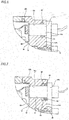
- insert through-holes 54, 54 passing through an insert bottom part 48a constituting a fitting insert 44a are formed at a plurality of circumferential places at a radially inner side of a middle part of the insert bottom part 48a with respect to a position facing a through-hole 25a of a mount part 24b in an assembled state.
- cap engagement parts 55, 55 each of which has a greater diameter dimension of an circumscribed circle than each of the insert through-holes 54, 54, are provided for portions around the insert through-holes 54, 54 at the axially outboard side with respect to an axially outboard surface of the insert bottom part 48a.
- Each of the cap engagement parts 55, 55 and the cap bottom part 23b are a resin portion filled inside each of the insert through-holes 54, 54, and are continuous with each other by means of cap continuous parts 56, 56.
- a shape of each of the cap engagement parts 55, 55 is not limited to a circular shape as shown, and various shapes may be adopted.
- Axial relative displacement between the fitting insert 44a and the cap body 20b is prohibited by axial engagement between an axially outboard surface of the insert bottom part 48a and an axially inboard surface of each of the cap engagement parts 55, 55.
- a flange part 49 is not formed at the fitting insert 44 like the above-described first example of the embodiment. That is, in this example, a insert cylindrical part 47a is formed by bending a radially outer end of the insert bottom part 48a axially outward at right angles. For this reason, since a folding process for forming the flange part 49 is not required when the fitting insert 44a is made by a stamping process, a process cost can be reduced.
- the fitting insert is made of an austenitic stainless steel plate
- a processed portion becomes brittle due to martensitic transformation associated with plastic deformation or is magnetized, and the folding process becomes difficult in some cases.
- the structure of this example in which the folding process is not required as described above may be preferably adopted.
- an oblique part 59 which is inclined to the axially outboard side toward the radially outer side, is formed at a radially outer end side portion of a insert bottom part 48b, and a radially outer end of this oblique part 59 is bent to the axially outboard side in a state where it is orthogonal to the insert bottom part 48b.
- an insert cylindrical part 47b can also be formed. In this case, a force for the bending process when the fitting insert is made is further reduced.
- a concave groove 57 is formed at an axially outboard end side portion of an outer circumferential surface of an insertion part 31b constituting a sensor holder 30b throughout the circumference.
- An O-ring 58 made of a rubber having a circular cross-sectional shape is set to this concave groove 57.
- this O-ring 58 is sandwiched between an inner circumferential surface of the through-hole 25a and a bottom part of the concave groove 57 in a state where it is elastically compressed.
- the concave groove 57 for setting the O-ring 58 is provided in the outer circumferential surface of the insertion part 31b.
- a concave groove 60 may be formed in the inner circumferential surface of the through-hole 25b of the mount part 24c. Since this concave groove 60 cannot be formed by injection molding, it is formed by cutting or the like after a cap is made by injection molding.
- an inner circumferential surface of a through-hole 25c of a mount part 24d may be formed in a stepped cylindrical shape in which a small diameter part 61 provided axially outboard and a large diameter part 62 provided axially inboard are continuous with each other via a step part 63.
- the O-ring 58 is fitted into an axially outboard end of the large diameter part 62, and a cylindrical plug member 64 made of a synthetic resin or a rubber is fitted into an axially inboard portion of this large diameter part 62 with respect to a position at which this O-ring 58 is internally fitted. In this way, the O-ring 58 is prevented from being axially displaced inside the large diameter part 62.
- the plug member 64 stops axially coming out of an axially outboard surface of the mounting flange part 32a constituting the sensor holder 30a.
- the flange part 49 is formed at the fitting insert 44a like the above-described first example of the embodiment, and the relative rotation and the axial relative displacement between the fitting insert 44a and the cap body 20b can be further prevented.
- Fig. 8 shows a third example of the embodiment of the present invention.
- a sensor seating surface 65 is formed at a portion, which faces a through-hole 25a of a cap bottom part 23b constituting a cap body 20c, of an axially inboard surface of an insert bottom part 48c of a fitting insert 44b, and has an axial thickness dimension L1 smaller than an axial thickness dimension L2 of the other portion (LI ⁇ L2).
- this sensor seating surface 65 is formed, for example, by coining a portion, which faces the through-hole 25a, of a fitting insert 44 (see Fig.
- an annular ridge part 66 is formed around the sensor seating surface 65, and protrudes axially inward with respect to the other portion of the axially inboard surface of the insert bottom part 48c.
- the formation of this sensor seating surface 65 is performed before the fitting insert 44b is molded in the cap body 20c by injection molding.
- detection accuracy is improved by reducing an axial distance between a detector of a sensor 29a and a detected surface of an encoder 13a.
- annular ridge part 66 of the fitting insert 44b and a portion of the cap body 20c which exists around this annular ridge part 66 are engaged in a circumferential direction of this cap body 20c, and thereby anti-rotation of the fitting insert 44b and the cap body 20c is promoted.
- This example may also be applied to the fitting insert as in the above-described second example of the embodiment.
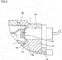
- Fig. 9 shows a fourth example of the embodiment of the present invention.
- a sensor seating surface 65a is formed at a portion, which faces a through-hole 25a of a mount part 24e constituting a cap body 20c, of an axially inboard surface of an insert bottom part 48d of a fitting insert 44c, and has an axial thickness dimension L1 smaller than an axial thickness dimension L2 of the other portion (L1 ⁇ L2).
- this sensor seating surface 65a is formed, for example, by bending a periphery of a portion, which faces the through-hole 25a, of a fitting insert 44a (see Figs.
- an annular ridge part 66a is formed around the sensor seating surface 65a and protrudes axially inward with respect to the other portion of the axially inboard surface of the insert bottom part 48d.
- the formation of this sensor seating surface 65a is performed before the fitting insert 44c is molded in the cap body 20c by injection molding.
- a shape of the ridge part formed by bending is not limited to the annular shape.
- a linear ridge part may be formed by bending only both the side portions in the radial direction out of a periphery of the portion corresponding to the sensor seating surface 65a or only both the side portions in the circumferential direction. Even in this case, this linear ridge part is formed, and thereby the portion corresponding to the sensor seating surface 65a is stretched.
- detection accuracy is improved by reducing an axial distance between a detector of a sensor 29a and a detected surface of an encoder 13a.
- annular ridge part 66a of the fitting insert 44c and a portion of the cap body 20c which exists around this annular ridge part 66a are engaged in a circumferential direction of this cap body 20c, and thereby anti-rotation of the fitting insert 44b and the cap body 20c is promoted.
- This example may also be applied to the fitting insert as in the above-described second example of the embodiment.
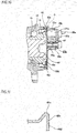
- Figs. 10 and 11 show a fifth example of the embodiment of the present invention.
- engagement ridge parts 67, 67 having arc-shaped cross sections are formed at a plurality of circumferential places at a radially inner side of a middle part of an axially inboard surface of an insert bottom part 48e constituting a fitting insert 44d, and protrude axially inward with respect to the other portion.
- each of the engagement ridge parts 67, 67 is formed by, for instance, a stamping process before the fitting insert 44d is molded in a cap body 20c by injection molding.
- a mounting nut 27b a nut having a structure in which axially inboard and outboard ends are open is adopted. Concave grooves 68a, 68b are formed throughout the circumference at two positions separated in the axial direction of an outer circumferential surface of this mounting nut 27b.
- This mounting nut 27b is buried in the cap body 20c by insert molding in a state where an axially outboard end face of this mounting nut 27b is brought into contact with (closed with) an axially inboard surface of the insert bottom part 48e.
- each of the engagement ridge parts 67, 67 and a portion of the cap body 20c which exists around each of the engagement ridge parts 67, 67 are engaged in a circumferential direction of this cap body 20c, and thereby relative rotation between the fitting insert 44d and the cap body 20c in a circumferential direction is prohibited.
- a structure in which engagement recess parts (not shown) recessed axially outward with respect to the other portion are formed in the axially inboard surface of the insert bottom part 48e may be adopted.
- each of the engagement recess parts and a portion of the cap body which is filled inside each of the engagement recess parts are engaged in the circumferential direction of this cap body, and thereby relative displacement between the fitting insert and the cap body in the circumferential direction can be prohibited.
- the anti-rotation notches 50, 50 may not be formed in a flange part 49b of the fitting insert 44d.
- the flange part may be formed to have an approximately triangular cross section like the flange part 49c shown in Fig. 11 . As a result, when this flange part 49c is formed, a force for a process is reduced.
- the present invention can be carried out by appropriately combining the examples of the above-described embodiment.
Landscapes
- Engineering & Computer Science (AREA)
- General Engineering & Computer Science (AREA)
- Mechanical Engineering (AREA)
- Physics & Mathematics (AREA)
- General Physics & Mathematics (AREA)
- Sealing Of Bearings (AREA)
- Rolling Contact Bearings (AREA)
Description
- The present invention relates to an improvement to a rolling bearing unit with a rotational speed detecting device, which is used for rotatably supporting a wheel (a non-driven wheel) of a vehicle on a suspension and for detecting a rotational speed of this wheel.
- A rolling bearing unit is used to rotatably support a wheel of a vehicle on a suspension. To control an Anti-lock Braking System (ABS) or a Traction Control System (TCS), there is a need to detect a rotational speed of the wheel. For this reason, rotatably supporting the wheel on the suspension and detecting the rotational speed of this wheel using a rolling bearing unit with a rotational speed detecting device in which the rotational speed detecting device is incorporated into the rolling bearing unit have recently been widely adopted.
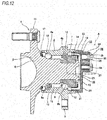
- As an example of a conventional structure of the rolling bearing unit with the rotational speed detecting device used for this purpose, a structure shown in
Figs. 12 and13 is described in Patent Document 1. The rolling bearing unit 1 with the rotational speed detecting device having this conventional structure rotatably supports ahub 3 which is a rotatable ring at an inner diameter side of anouter ring 2 which is a stationary ring. - The
outer ring 2 include double rows ofouter ring raceways 4a, 4b on an inner circumferential surface thereof, and a stationary-side flange 5 on an outer circumferential surface thereof. Theouter ring 2 is supported by a knuckle (not shown) constituting the suspension and is not rotatable when used. - The
hub 3 is formed by combining ahub body 6 and aninner ring 7 and includes double rows ofinner ring raceways hub 3 is supported at the inner diameter side of theouter ring 2 in the same center as thisouter ring 2. Specifically, theinner ring raceway 8a of an axially outboard row is directly formed at an axially middle portion of an outer circumferential surface of thehub body 6, and similarly theinner ring 7, on an outer circumferential surface of which theinner ring raceway 8b of an axially inboard row is formed is fitted around and fixed to a small diameter step part 9 formed at an axially inboard end side portion (where the axially inboard side refers to a center side of a vehicle body in a width direction in a state assembled to the suspension, whereas the axially outboard side refers to an outboard side of the vehicle body in the width direction. This applies to the entire specification and claims). An axially inboard end face of theinner ring 7 is pressed by a caulkingpart 10 formed by plastically deforming an axially inboard end of thehub body 6 radially outward. A rotation-side flange 11 for supporting the wheel at an axially outboard end of thehub body 6 is provided at a portion which protrudes axially outward with respect to an axially outboard end opening of theouter ring 2. - A plurality of
rolling elements outer ring raceways 4a, 4b and theinner ring raceways hub 3 is rotatably supported on the inner diameter side of theouter ring 2. - An
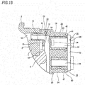
encoder 13 is fitted around and fixed to a portion deviating from the axiallyinboard ring raceway 8b inward at an axially inboard end of an outer circumferential surface of theinner ring 7. Thisencoder 13 is formed by combining asupport ring 14, which is formed of a magnetic metal plate in an approximate L-shaped cross section and is of an annular shape as a whole, and anencoder body 16 which is attached to a side surface of acircular ring part 15 constituting thissupport ring 14. Since thisencoder body 16 is formed of a permanent magnet such as a rubber magnet into which ferrite powder is mixed and is of a circular ring shape as a whole, it is magnetized in the axial direction, and changes directions of magnetization in an alternate manner at regular intervals in a circumferential direction. Therefore, S and N poles are disposed on an axially inboard surface or a detected surface of theencoder body 16 in an alternate manner at regular intervals. - A
seal ring 17 is installed between the axially outboard end opening of theouter ring 2 and the outer circumferential surface of the axially middle portion of thehub body 6, and acap 19 is mounted on an axially inboard end opening of theouter ring 2. Thereby, opposite end openings of aspace 18 in which therolling elements encoder 13 are installed are sealed, and grease enclosed within thisspace 18 is prevented from leaking out to an external space or foreign materials which are present in the external space are prevented from invading thisspace 18. - The
cap 19 includes a bottomedcylindrical cap body 20 made by injection-molding a synthetic resin and afitting ring 21 which is formed in an L-shaped cross section by stamping a non-magnetic metal plate and is of an annular shape as a whole. Thecap body 20 includes a capcylindrical part 22 and acap bottom part 23 which closes an axially inboard end opening of the capcylindrical part 22. Thefitting ring 21 is fixed (molded) to an inner diameter side portion of a tip of the capcylindrical part 22. Amount part 24 expanded axially inward (increased in an axial thickness dimension) compared to the other portion is provided at a radially outer side portion of thecap bottom part 23. A portion of themount part 24 which axially faces the detected surface of the encoder 13 (the encoder body 16) is formed with a through-hole 25 which axially penetrates therethrough. A bottomed cylindricalsensor insertion cup 26 made of a non-magnetic stainless steel plate is molded into the through-hole 25. Thissensor insertion cup 26 is buried in themount part 24 by insert-molding at the injection molding of thecap body 20. Further, amounting nut 27, on an inner circumferential surface of which internal threads are formed, is also buried in a portion of themount part 24 which deviates from the through-hole 25 by insert-molding. - A
sensor unit 28 for detecting a rotational speed is supported and fixed to thecap 19. Thesensor unit 28 includes asensor 29 and asensor holder 30. Since a magnetism detecting element such as a Hall element, a magnetic resistance element, or the like is provided for a detector, thesensor 29 changes an output signal in response to a change in characteristics of the detected surface of theencoder 13. Thesensor holder 30 is formed by injection-molding a synthetic resin and includes aninsertion part 31 for holding thesensor 29 and amounting flange part 32 for fixing thecap 19. Thissensor unit 28 is fixed to the cap 19 (the mount part 24) by screwing an external thread part of abolt 34, which is inserted into a through-hole formed in themounting flange part 32, onto an internal thread part of themounting nut 27 in a state where theinsertion part 31 is inserted to thesensor insertion cup 26. - According to the rolling bearing unit 1 with the rotational speed detecting device of the conventional structure having the configuration as described above, the wheel fixed to the
hub 3 can be rotatably supported with respect to the suspension supporting theouter ring 2. When theencoder 13 is rotated together with thehub 3 with the rotation of the wheel, the N and S poles which are present on the detected surface of theencoder 13 alternately pass through the vicinity of a detection part of thesensor 29 facing the detected surface of theencoder 13 via abottom plate part 35 of thesensor insertion cup 26. As a result, a direction of magnetic flux flowing in the magnetism detecting element constituting thesensor 29 is alternately changed, and a characteristic of this magnetism detecting element is alternately changed. In this way, a frequency at which the characteristic of the magnetism detecting element is changed is proportional to the rotational speed of thehub 3. Thus, when the output signal of thesensor 29 is sent to a controller (not shown), the ABS or the TCS can be suitably controlled. In the conventional structure, even in a state before thesensor unit 28 is assembled on an assembly process of, for instance, a vehicle builder, since thespace 18 in which theencoder 13 is installed can be sealed by the cap 19 (and the sensor insertion cup 26), it is possible to effectively prevent foreign materials from sticking to thisencoder 13. - However, in the conventional structure as described above, there is a possibility of causing the following problems.
- That is, in the conventional structure, a set of upper and lower molding dies 36, 37 as shown in, for instance,
Fig. 14 is used to manufacture thecap 19. Specifically, a molten synthetic resin is fed into acavity 38 which is defined with these upper and lower molding dies 36, 37 brought into axially contact with each other and has a shape matched with an outer surface shape of thecap 19. Particularly, in the conventional structure, the synthetic resin is fed with thesensor insertion cup 26 set in this cavity 38 (insert molding is performed). When this insert molding is performed, thebottom plate part 35 constituting thissensor insertion cup 26 is brought into contact with a part of thelower molding die 37 in order to regulate a position at which thesensor insertion cup 26 is installed, and similarly a part of theupper molding die 36 is butted against (bitten into) an axially inboard surface (curved surface) of abent part 41 which is a connecting part between acylindrical part 39 and aflange part 40 which constitute thesensor insertion cup 26. - When the insert molding is performed in the way as described above, the
cylindrical part 39 of thissensor insertion cup 26 may be elastically deformed (expanded) radially outward based on a pressing force for thesensor insertion cup 26 of theupper molding die 36. Injection molding is performed in this state, and thereafter, when thecap 19 is extracted from the cavity 38 (when the pressing force caused by theupper molding die 36 is removed), since thecylindrical part 39 is elastically restored (reduced in its diameter), there is a possibility of a gap occurring at a coupling surface between the outer circumferential surface of thecylindrical part 39 and a portion of the synthetic resin which is present around thiscylindrical part 39. When a foreign material such as water is invaded into this gap, there is a possibility that this foreign material further progresses axially outward to enter from an axially inboard end of the coupling surface to thespace 18. - Incidentally, when the synthetic resin is cooled and solidified, it is contracted by a reduction in volume, which is generally known. For this reason, it is also thought that a portion, which is present around this
cylindrical part 39, of a synthetic resin of which thecap body 20 is formed is contracted, and thereby the gap resulting from the above-described cause is extinguished and reduced. However, an inner diameter dimension of the through-hole 25 is typically about 10 mm, and an amount of contraction associated with the solidification is slight. For this reason, it is difficult to completely extinguish the gap.Patent document 2 shows a further example of a rolling bearing unit with a rotational speed detectin device. -
- Patent Document 1:
JP-A-2011-80500 - Patent Document 2:
JP-A-2012-106547 - The present invention has been made in view of the above circumstances and provides a rolling bearing unit with a rotational speed detecting device capable of sufficiently securing sealing performance by a cap.
- A rolling bearing unit with a rotational speed detecting device of the present invention is used to rotatably support a wheel for a non-driven wheel on a suspension such as a knuckle and includes an outer ring, a hub, a plurality of rolling elements, an encoder, a cap, and a sensor unit according to claim 1.
- In implementing the present invention, preferably, an axial thickness dimension of a portion of the insert bottom part of the fitting insert, which axially faces the through-hole is smaller than a thickness dimension of a remaining portion of the insert bottom part other than the portion.
- In implementing the present invention, preferably, a seal member is provided at a portion between an inner circumferential surface of the through-hole and an outer circumferential surface of the sensor holding part.
- In implementing the present invention, preferably, the mounting nut has a tubular shape, both ends of which are axially open. An axially inboard end opening of the mounting nut is open to an axially inboard surface of the cap bottom part, and the mounting nut is disposed in a state where an axially outboard end opening thereof is closed by the insert bottom part.
- In implementing the present invention, preferably, an anti-rotation structure for prohibiting relative rotation between the fitting insert and the cap body by engagement between the fitting insert and the cap body in a circumferential direction is provided between the fitting insert and the cap body.
- In the present invention a retaining mechanism for prohibiting axial relative displacement between the fitting insert and the cap body by axial engagement between the fitting insert and the cap body is provided between the fitting insert and the cap body.
- In implementing the present invention, preferably, the insert cylindrical part is directly fitted into the axially inboard end of the outer ring.
- When the insert cylindrical part is directly fitted into the axially inboard end of the outer ring, preferably, a concave groove, which is open to an axially outboard side and a radially inner side, is formed throughout an inner circumferential surface of an axially outboard end of the cap cylindrical part. In a state where an axially outboard end face of the cap cylindrical part comes into contact with an axially inboard end face of the outer ring, an annular seal member is fitted around a portion, which radially overlaps the concave groove, of the outer circumferential surface of the insert cylindrical part, and is axially sandwiched between the axially inboard end face of the outer ring and an axial side surface of the concave groove.
- According to the present invention configured as described above, sealing performance by the cap can be sufficiently secured.
- That is, in the present invention, in the state where the cap is mounted on the axially inboard end of the outer ring by the insert cylindrical part of the fitting insert, the cap closes the axially outboard end opening of the through-hole formed in the cap bottom part. Therefore, even when a foreign material such as water is invaded into an axially outboard end of the portion between the outer circumferential surface of the sensor holder and the inner circumferential surface of the through-hole, this foreign material can be prohibited from being invaded into the space in which the rolling elements or the encoder is installed by the axially inboard surface of the insert bottom part. That is, the formation of the gap connected to the space in which the encoder is installed between the through-hole provided in the cap body and the sensor insertion ring fitted into this through-hole, which becomes the problem in the above-described conventional structure, can be avoided. Therefore, according to the present invention, sealing performance by the cap can be sufficiently secured.
- The axial thickness dimension of the portion of the insert bottom part of the fitting insert, which axially faces the through-hole, is smaller than the thickness dimension of the remaining portion of the insert bottom part other than the portion. Therefore, even when a thickness dimension of the metal plate forming this fitting insert is increased to secure rigidity of the fitting insert, detection accuracy of the sensor is improved by reducing the axial distance between the sensor held in the sensor holder and the encoder.
- The seal member is provided at the portion between the inner circumferential surface of the through-hole of the cap body and the outer circumferential surface of the sensor holder. Therefore, a foreign material such as water is effectively prevented from being invaded into the relevant portion. As a result, the water invaded into the relevant portion is prevented from being frozen and expanded to damage the sensor, or a gap is prevented from occurring at a coupled part between the fitting insert and the cap body.
- The mounting nut has the tabular shape, both ends of which are axially open. Therefore, in comparison with a mounting nut having a structure in which one axial end thereof is closed, an internal thread part can be easily machined by, for instance, rolling, and a manufacturing cost is reduced. In a state where the mounting nut is molded in the cap bottom part, the axially outboard end opening of the mounting nut is closed by the fitting bottom part. Therefore, even when a foreign material such as water is invaded into the axially outboard end of the portion between the inner circumferential surface (the internal thread part) of the mounting nut and the outer circumferential surface (the external thread part) of the bolt, this foreign material can be prohibited from being invaded into the space in which the rolling elements or the encoder is install by the axially inboard surface of the insert bottom part. Accordingly, the sealing performance by the cap can be sufficiently secured.
- The anti-rotation mechanism or the retaining mechanism is provided between the fitting insert and the cap body. Therefore, a coupling and fixing force between the fitting insert and the cap body can be made strong.
- The insert cylindrical part is directly fitted into the axially inboard end of the outer ring. Therefore, like when this insert cylindrical part is fitted into the axially inboard end of the outer ring via the cap cylindrical part of the cap body made of a synthetic resin, the cap cylindrical part is unlikely to be deformed in use, and no gap is likely to occur between the inner circumferential surface of the outer ring and the outer circumferential surface of the cap cylindrical part.
- Therefore, the sealing performance by the cap can be sufficiently secured.
- If the annular seal member is fitted around a portion of the outer circumferential surface of the insert cylindrical part, which radially overlaps the concave groove in the outer circumferential surface of the axially outboard end of the insert cylindrical part is formed, a foreign material such as water can be effectively prevented from being invaded into the fitting portion between the outer circumferential surface of the insert cylindrical part and the inner circumferential surface of the axially inboard end of the outer ring.
-
-
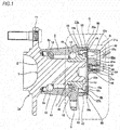
Fig. 1 is a cross-sectional view showing a rolling bearing unit with a rotational speed detecting device according to a first example of an embodiment of the present invention. -
Fig. 2A is an enlarged view of a part B ofFig. 1 . -
Fig. 2B is a view when a fitting insert is extracted from the rolling bearing unit with the rotational speed detecting device ofFig. 1 and a part thereof in a circumferential direction is viewed from an axially inboard side. -
Fig. 3 is a view showing another example of a shape of a flange part of the fitting insert in the rolling bearing unit with the rotational speed detecting device ofFig. 1 . -
Fig. 4A is a view showing a portion which corresponds to a part C ofFig. 1 in a rolling bearing unit with a rotational speed detecting device according to a second example of the embodiment of the present invention. -
Fig. 4B is a view of the fitting insert in the rolling bearing unit with the rotational speed detecting device ofFig. 4A when viewed from an axially outboard side. -
Fig. 5 is a view showing a portion which corresponds to the part B ofFig. 1 in the rolling bearing unit with the rotational speed detecting device according to the second example of the embodiment of the present invention. -
Fig. 6 is a view showing an example of a seal structure between an inner circumferential surface of a through-hole of a cap body and an outer circumferential surface of an insertion part of a sensor holder in the second example of the embodiment of the present invention. -
Fig. 7 is a view showing another example of the seal structure between the inner circumferential surface of the through-hole of the cap body and the outer circumferential surface of the insertion part of the sensor holder in the second example of the embodiment of the present invention. -
Fig. 8 is an enlarged view showing a portion which corresponds to the part B ofFig. 1 in a rolling bearing unit with a rotational speed detecting device according to a third example of the embodiment of the present invention. -
Fig. 9 is an enlarged view showing a portion which corresponds to the part B ofFig. 1 in a rolling bearing unit with a rotational speed detecting device according to a fourth example of the embodiment of the present invention. -
Fig. 10 is a view showing a portion which corresponds to the part C ofFig. 1 in a rolling bearing unit with a rotational speed detecting device according to a fifth example of the embodiment of the present invention. -
Fig. 11 is a view showing an example of a configuration of a flange part at a part D ofFig. 10 . -
Fig. 12 is a cross-sectional view showing a conventional rolling bearing unit with a rotational speed detecting device. -
Fig. 13 is an enlarged view of a part A ofFig. 12 . -
Fig. 14 is a partial cross-sectional view of a molding die, showing a process of manufacturing a cap in the conventional rolling bearing unit with the rotational speed detecting device. -
Figs. 1 to 3 show a first example of an embodiment of the present invention. A feature of this example is that a structure of acap 19a for closing an axially inboard end opening of anouter ring 2 is devised. Since structures and operational effects of other portions are basically the same as in the above-described conventional structure, overlapping illustration and description will be omitted or simplified. The following description is based on characteristic portions of this example and the portions which are not described previously. - A rolling bearing unit 1a with a rotational speed detecting device of this example rotatably supports a wheel which is a non-driven wheel on a suspension such as a knuckle, detects a rotational speed of this wheel, and rotatably supports a
hub 3 which is a rotatable ring at an inner diameter side of theouter ring 2 which is a stationary ring via a plurality of rollingelements - The
outer ring 2 and ahub body 6 constituting thehub 3 are made of medium-carbon steel such as S53C, and a hardening treatment such as high-frequency hardening is performed at least on surfaces ofraceways inner ring 7 constituting thehub 3 and each of the rollingelements elements 12 are not limited to balls as shown inFig. 1 . When the rolling bearing unit 1a with the rotational speed detecting device of this example is used for a heavy vehicle, tapered rollers may be used as the rollingelements 12. - An
encoder 13a is fitted around and fixed to (press-fitted into and fixed to) an axially inboard end (a right end ofFig. 1 ) of an outer circumferential surface of theinner ring 7. Thisencoder 13a includes asupport ring 14a and anencoder body 16a. Thesupport ring 14a is formed in an approximately L-shaped cross section in an annular shape as a whole by stamping ferritic stainless steel plate such as SUS430 or a cold rolled steel plate such as SPCC on which a rust prevention treatment is performed. Thesupport ring 14a includes a tubularfitting cylinder part 42, anoutward flange part 43 provided in a state it is bent radially outward from an axially outboard end (a left end ofFig. 1 ) of thefitting cylinder part 42, and acircular ring part 15a provided in a state where it is bent radially inward from an axially inboard end of thefitting cylinder part 42. Thefitting cylinder part 42 is provided with a small diameter part which is provided at an axially outboard half part and is directly fitted around the axially inboard end of theinner ring 7, and a tapered part which is provided at an axially inboard half part and is inclined in a direction in which an outer diameter dimension is increased toward the axially inboard side. In this example, in a state where thissupport ring 14a is press-fitted into the axially inboard end of theinner ring 7 in the axial direction, an axial position of thesupport ring 14a is regulated such that an axially inboard surface of thecircular ring part 15a and an axially inboard end face of theouter ring 2 are located on the same virtual plane. Since the whole of theencoder body 16a is formed in a circular ring shape by a rubber magnet in which a magnetic material such as ferrite powder is mixed or a permanent magnet such as a plastic magnet, theencoder body 16a is magnetized in the axial direction, and a direction of the magnetization is changed in an alternate manner at regular intervals in a circumferential direction. - In a state where this
encoder body 16a is attached to the axially inboard surface of thecircular ring part 15a, an axially inboard surface (a detected surface) of thisencoder body 16a is located at the axially inboard side with respect to an axially inboard end face of acaulking part 10 formed at an axially inboard end of thehub body 6. - The
cap 19a mounted on an axially inboard end of theouter ring 2 includes acap body 20a made of a synthetic resin, afitting insert 44 which is disposed inside thiscap body 20a and is made of a metal, and a mountingnut 27a disposed (inserted) in thiscap body 20a. - The
cap body 20a is made, for example, by injection-molding a polyamide resin mixture material in which fiberglass is adequately added to apolyamide 66 resin. If an amorphous aromatic polyamide resin (modified polyamide 6T/6I) and a low water-absorbing aliphatic polyamide resin (apolyamide 11 resin, apolyamide 12 resin, a polyamide 610 resin, or a polyamide 612 resin) are adequately added to a polyamide resin, water resistance can be further improved. - The
cap body 20a made in this way is formed in the shape of a bottomed cylinder including a capcylindrical part 22a and a capbottom part 23a closing an axially inboard end opening of this capcylindrical part 22a. - A
concave groove 45, which has a rectangular cross section and is open to the axially outboard side and the radially inner side, is formed throughout an inner circumferential surface of an axially outboard end of the capcylindrical part 22a. An outer diameter side portion from an axially outboard end opening of theconcave groove 45 of an axially outboard end face of the capcylindrical part 22a is formed in a flat surface shape to abut against the axially inboard end face of theouter ring 2. - A portion of the cap
bottom part 23a in a circumferential direction is provided with amount part 24a which is expanded axially inward with respect to the other portion (or whose axial thickness dimension is increased). A portion of themount part 24a which axially faces the detected surface of theencoder 13a (theencoder body 16a) in an assembled state is formed with a through-hole 25a which axially penetrates therethrough. A holdinghole part 46 for holding the mountingnut 27a at an inner side thereof is provided at a position of themount part 24a which is shifted from the through-hole 25a to the radially inner side. This holdinghole part 46 has the shape of a bottomed cylinder in which an axially inboard end thereof is open and an axially outboard end is closed, and is formed by insert-molding the mountingnut 27a in the capbottom part 23a as will be described below. - The
fitting insert 44 is formed in a bottomed cylindrical shape (in cross-sectional shape having an approximately C-shaped petri dish shape) by stamping a non-magnetic metal plate such as an austenitic stainless steel plate or aluminum based alloy plate. Thisfitting insert 44 includes an insertcylindrical part 47, an insertbottom part 48 which closes an axially inboard end opening of this insertcylindrical part 47, and aflange part 49 which corresponds to a retaining mechanism of the claims. Thisflange part 49 is formed in a state where it is bent radially outward from an axially inboard end of the insertcylindrical part 47 at right angles and its middle portion is folded back 180° radially inward. A radially inner end of theflange part 49 is continuous with a radially outer end of the insertbottom part 48. In this example, axially inboard surfaces of theflange part 49 and the insertbottom part 48 are mutually located on the same plane. Theflange part 49 may be formed, for instance, in a state where it is inclined axially inward toward the radially outer side like aflange part 49a shown inFig. 3 . When theflange part 49a inclined axially inward is formed, if theflange part 49a is formed such that the entire insertbottom part 48 is pulled radially outward, the flatness of this insertbottom part 48 is improved. -
Anti-rotation notches flange part 49 in a state where they are open to axially inboard and outer sides of theflange part 49 and to the radially outer edge of theflange part 49. Each of theanti-rotation notches flange part 49 in the circumferential direction in a non-circular shape or bending (crushing) the part radially inward. - The
fitting insert 44 having this configuration is molded at an inner diameter side of the capcylindrical part 22a of thecap body 20a and at an axially outboard side of the capbottom part 23a at injection molding of thecap body 20a, and thereby is fixed to thiscap body 20a. - Specifically, an axially inboard half part of the insert
cylindrical part 47 is fixed to the inner diameter side of the capcylindrical part 22a with theflange part 49 buried in the capcylindrical part 22a, and similarly an axially outboard half part of the insertcylindrical part 47 protrudes axially outward with respect to the axially outboard end face of this capcylindrical part 22a. An axially inboard surface of the insertbottom part 48 is fixed to an axially outboard surface of the capbottom part 23a. In this state, an axially outboard end opening of this capbottom part 23a of the through-hole 25a is closed by a part of the axially inboard surface of the insert bottom part 48 (where a part of the axially inboard surface of the insertbottom part 48 is exposed to the through-hole 25a). - In the fixed state as described above, the axially inboard and outboard sides of the
flange part 49 and thecap body 20a are axially engaged, and thereby axial relative displacement between thefitting insert 44 and thecap body 20a is prohibited. The both sides of theflange part 49 in the circumferential direction of each of theanti-rotation notches cap body 20a which is filled inside each of theanti-rotation notches fitting insert 44 and thecap body 20a is prohibited. - The mounting
nut 27a has the shape of a bottomed cylinder, on an inner circumferential surface of which aninternal thread part 51 is formed and in an outer circumferential surface of which aconcave groove 52 is formed throughout the circumference of an axially middle part, and is buried in a portion corresponding to the holdinghole part 46 of themount part 24a. - As described above, in a state where the mounting
nut 27a is buried in thecap body 20a, axially inboard and outboard sides of theconcave groove 52 and a portion of thiscap body 20a which is filled inside theconcave groove 52 are axially engaged, and thereby displacement of the mountingnut 27a with respect to thecap body 20a is prohibited. - An axially inboard end face of the mounting
nut 27a is located on the same virtual plane as an axially inboard surface of themount part 24a, and theinternal thread part 51 is open to the axially inboard surface of themount part 24a. Herein, since an axial dimension of the mountingnut 27a is shorter than an axial dimension of themount part 24a, an axially outboard end face of the mountingnut 27a is buried in themount part 24a in a state where it is located inside in the axial direction with respect to an axially outboard end face of the capbottom part 23a. The axially outboard end face of the mountingnut 27a may be located on the same virtual plane as the axially outboard end face of the capbottom part 23a. - In this example, the mounting
nut 27a has a structure (a cap nut) in which it is not penetrated in the axial direction. For this reason, the mountingnut 27a does not need to be screwed on the external threads as shown inFig. 14 at the insert molding, and workability of the insert molding can be improved. On the other hand, when the mounting nut has a structure in which it is penetrated in the axial direction, insert molding is performed in a state where the mounting nut is screwed on external threads (seeFig. 14 ) such that no resin is thrust into this mounting nut. However, even when the mounting nut penetrated in the axial direction is used as in a fifth example of the embodiment which will be described below, if the insert molding is performed in a state where the axially outboard end opening of this mounting nut is closed with the axially inboard surface of the insert bottom part, there is no need to be screwed on the external thread part like the structure in which the mounting nut is not penetrated in the axial direction. - A method of fixing the mounting
nut 27a to thecap body 20a is not limited to the insert molding. A nut insertion hole, which has a bottomed cylindrical shape and in an inner circumferential surface of which a locking concave groove which is long in the axial direction is formed, may be formed in a portion of thecap body 20a which corresponds to the holdinghole part 46, and a mounting nut, on an outer circumferential surface of which a locking convex ridge which is long in the axial direction, or the like is provided, may be pressed into the nut insertion hole in a state where phases of the locking convex ridge and the locking concave groove are aligned. Alternatively, a nut, on an outer circumferential surface of which convex ridges such as serration which are long in the axial direction are formed, may be pressed into a nut insertion hole, which is formed in the shape of a bottomed cylinder, in an inner circumferential surface of which concave grooves or the like are not formed, and the nut may be locked by forming the concave grooves in the inner circumferential surface of the nut insertion hole according to the convex ridges. - The
cap 19a having the configuration as described above can be formed by injection molding (axial draw molding) using a device provided with a molding die insertion part, which has an outer circumferential surface shape matched with the inner circumferential surface shape of the through-hole 25a, for a part of one of the pair of molding dies (the upper molding die 36 and the lower molding die 37) as shown inFig. 14 in a state where the mountingnut 27a and thefitting insert 44 are disposed in thecavity 38 defined between these molding dies. - The
cap 19a having the configuration as described above is assembled to theouter ring 2 by directly fitting (metal fitting) the outer circumferential surface of the axially outboard half part of thefitting insert 44 into the inner circumferential surface of the axially inboard end of theouter ring 2 and by abutting the axially outboard end face of the capcylindrical part 22a against the axially inboard end face of theouter ring 2 in a state where a O-ring 53, which is formed of a rubber in a circular cross-sectional shape and which corresponds to an annular seal member in the claims, is mounted on (fitted around) a portion which radially overlaps theconcave groove 45 of the capcylindrical part 22a out of the outer circumferential surface of the insertcylindrical part 47. In this assembled state, the axially outboard surface of the insertbottom part 48 closely faces the detected surface of theencoder 13a via a predetermined axial gap (an air gap). - In the assembled state as described above, the O-
ring 53 is sandwiched between an axial side surface of theconcave groove 45 and the axially inboard end face of theouter ring 2 in a state where it is axially compressed. For this reason, even when a foreign material such as water is invaded from a abutting part between the axially outboard end face of the capcylindrical part 22a and the axially inboard end face of theouter ring 2, this foreign material is effectively prevented from reaching a metal fitting part between the outer circumferential surface of the insertcylindrical part 47 and the inner circumferential surface of the axially inboard end of theouter ring 2 due to the O-ring 53. - In this example, an end of a coupling surface between the
cap body 20a and thefitting insert 44 of thecap 19a (a boundary surface between both themembers 20a, 44) is not present in thespace 18 in which the rollingelements encoder 13a is installed. That is, the coupling surface is not provided in a state where it is directly continuous with (exposed to) thisspace 18. For this reason, for example, a foreign material such as water invaded from a portion or the like between the inner circumferential surface of the through-hole 25a of themount part 24a and an outer circumferential surface of asensor holder 30a (to be described below) is not invaded into thespace 18 along a gap occurring at the coupling surface between thecap body 20a and thefitting insert 44. In this example, an axially outboard end of the coupling surface is located at a radially inner end of the axial side surface of theconcave groove 45. For this reason, even when a foreign material such as water is invaded up to the position along the gap occurring at the coupling surface between thecap body 20a and thefitting insert 44, the foreign material can be prevented from being invaded into thespace 18 by the O-ring 53. - In this example, a
sensor unit 28a for detecting a rotational speed is supported and fixed to thecap 19a having the configuration as described above. Thissensor unit 28a includes asensor 29a and asensor holder 30a. Since thesensor 29a installs therein a magnetism detecting element such as a Hall element, a magnetic resistance element, or the like on a detector, thesensor 29a changes an output signal in response to a change in characteristics of the detected surface of theencoder 13a. Since thesensor holder 30a is formed by injection-molding a synthetic resin such as a polyamide resin, thesensor holder 30a includes aninsertion part 31a which holds thesensor 29a at a tip thereof (an axially outboard end thereof), has an outer diameter dimension equal to or slightly smaller than an inner diameter dimension of the through-hole 25a of the capbottom part 23a, corresponds to a sensor holding part in the claims, and has an approximately column shape (a rod shape), and a mountingflange part 32a which is provided at a base end of thisinsertion part 31a and is intended to be fixed to thecap 19a. Thissensor unit 28a is fixed to thecap 19a (themount part 24a) by screwing anexternal thread part 33 of abolt 34, which is inserted into a through-hole 69 formed in the mountingflange part 32a, to aninternal thread part 51 of the mountingnut 27a in a state where theinsertion part 31a is directly inserted into the through-hole 25a. - In a state where the
sensor unit 28a is supported and fixed to thecap 19a, a tip face of theinsertion part 31a (an axially outboard end face thereof) and the axially inboard surface of the insertbottom part 48 constituting thefitting insert 44 closely face each other via a minute axial gap or come into contact with each other. In this state, thesensor 29a (of the detector) held on the tip of theinsertion part 31a faces the detected surface of theencoder 13a via the insertbottom part 48. - Even in this example having the configuration as described above, the wheel fixed to the
hub 3 can be rotatably supported on the suspension supporting theouter ring 2. When theencoder 13a is rotated together with thehub 3 with the rotation of the wheel, the N and S poles which are present on the detected surface of theencoder 13a alternately pass the vicinity of the detector of thesensor 29a facing the detected surface of theencoder 13a via the insertbottom part 48 of thefitting insert 44. As a result, a direction of magnetic flux flowing in the magnetism detecting element constituting thesensor 29a is alternately changed, and a characteristic of this magnetism detecting element is alternately changed. In this way, a frequency at which the characteristic of the magnetism detecting element is changed is proportional to the rotational speed of thehub 3. Thus, if the output signal of thesensor 29a is sent to a controller (not shown), an ABS or a TCS can be suitably controlled. - Particularly, in this example, sealing performance by the
cap 19a can be sufficiently secured. - That is, in the present invention, in a state where the
cap 19a is assembled by fitting and fixing the insertcylindrical part 47 of thefitting insert 44 into and to the inner circumferential surface of the axially inboard end of theouter ring 2, the axially inboard surface of the insertbottom part 48 closes the axially outboard end opening of the through-hole 25a formed in the capbottom part 23a. For this reason, even when a foreign material such as water is invaded into an axially outboard end (an inner part) of the portion between the outer circumferential surface of theinsertion part 31a constituting thesensor holder 30a and the inner circumferential surface of the through-hole 25a, the foreign material can be prevented from being invaded into thespace 18 in which the rollingelements encoder 13a is installed by the axially inboard surface of the insertbottom part 48. - In this example, the end of the coupling surface between the
cap body 20a and thefitting insert 44 of thecap 19a (the boundary surface between both themembers 20a, 44) is not present in thespace 18. That is, even when a gap is formed between the through-hole 25a and theinsertion part 31a fitted into the through-hole 25a provided in thecap body 20a, which is problematic in the above-described conventional structure, this gap does not lead to thespace 18. For this reason, a foreign material such as water is not invaded into thespace 18 along a gap occurring at the coupling surface. Therefore, according to the present invention, the sealing performance by thecap 19a can be sufficiently secured - In this example, the
flange part 49 is formed at thefitting insert 44, and the axially inboard and outboard sides of thisflange part 49 and thecap body 20a are axially engaged. For this reason, axial relative displacement between thefitting insert 44 and thecap body 20a can be prevented. - The both sides of each of the
anti-rotation notches flange part 49 in the circumferential direction and the portion of thecap body 20a which is filled in each of theanti-rotation notches fitting insert 44 and thecap body 20a can be prevented. - In this example, the outer circumferential surface of the insert
cylindrical part 47 of thefitting insert 44 is directly fitted into the inner circumferential surface of the axially inboard end of theouter ring 2. For this reason, even in continuous use, a gap or the like is prevented from occurring at this fitting part. - That is, like the above-described conventional structure, in the structure in which the fitting ring 21 (see
Fig. 12 ) is fitted into the inner circumferential surface of the axially inboard end of theouter ring 2 via the capcylindrical part 22 of thecap body 20 formed of a synthetic resin, deformation such as settling is to occur at the capcylindrical part 22 by use, and a gap is likely to occur at the fitting part between theouter ring 2 and the capcylindrical part 22. On the other hand, in this example, the insertcylindrical part 47 made of a metal is directly metal-fitted into theouter ring 2. For this reason, the gap based on the deformation such as settling can be prevented from occurring at this insertcylindrical part 47. Therefore, according to this example, the sealing performance by thecap 19a can be sufficiently secured. The axial gap between thesensor 29a and theencoder 13a can also be constantly secured for a long period of time. - Further, in this example, the O-
ring 53 is fitted around the portion which radially overlaps theconcave groove 45 of the capcylindrical part 22a out of the outer circumferential surface of the insertcylindrical part 47. For this reason, a foreign material such as water invaded from the gap between the axially inboard end face of theouter ring 2 and the axially outboard end face of the capcylindrical part 22a, and the gap occurring at the coupling surface between thecap body 20a and thefitting insert 44 can be effectively prevented from being invaded into the fitting part between the outer circumferential surface of the insertcylindrical part 47 and the inner circumferential surface of the axially inboard end of theouter ring 2. -
Figs. 4 to 7 show a second example of the embodiment of the present invention. - In a rolling bearing unit with a rotational speed detecting device of this example, insert through-
holes bottom part 48a constituting afitting insert 44a are formed at a plurality of circumferential places at a radially inner side of a middle part of the insertbottom part 48a with respect to a position facing a through-hole 25a of amount part 24b in an assembled state. - In a state where the
fitting insert 44a as described above is molded in acap body 20b by injection molding,cap engagement parts holes holes bottom part 48a. Each of thecap engagement parts bottom part 23b are a resin portion filled inside each of the insert through-holes continuous parts cap engagement parts - In this example, relative rotation between the
fitting insert 44a and thecap body 20b is prohibited by circumferential engagement between an inner surface of each of the insert through-holes continuous parts - Axial relative displacement between the
fitting insert 44a and thecap body 20b is prohibited by axial engagement between an axially outboard surface of the insertbottom part 48a and an axially inboard surface of each of thecap engagement parts - In this example, since the relative rotation and the axial relative displacement between the
fitting insert 44a and thecap body 20b is prohibited by the configuration as described above, aflange part 49 is not formed at thefitting insert 44 like the above-described first example of the embodiment. That is, in this example, a insert cylindrical part 47a is formed by bending a radially outer end of the insertbottom part 48a axially outward at right angles. For this reason, since a folding process for forming theflange part 49 is not required when thefitting insert 44a is made by a stamping process, a process cost can be reduced. Particularly, when the fitting insert is made of an austenitic stainless steel plate, a processed portion becomes brittle due to martensitic transformation associated with plastic deformation or is magnetized, and the folding process becomes difficult in some cases. Thus, the structure of this example in which the folding process is not required as described above may be preferably adopted. - When the structure of this example is implemented, as shown in
Fig. 5 , anoblique part 59, which is inclined to the axially outboard side toward the radially outer side, is formed at a radially outer end side portion of a insertbottom part 48b, and a radially outer end of thisoblique part 59 is bent to the axially outboard side in a state where it is orthogonal to the insertbottom part 48b. Thereby, an insertcylindrical part 47b can also be formed. In this case, a force for the bending process when the fitting insert is made is further reduced. - In this example, a
concave groove 57 is formed at an axially outboard end side portion of an outer circumferential surface of aninsertion part 31b constituting asensor holder 30b throughout the circumference. An O-ring 58 made of a rubber having a circular cross-sectional shape is set to thisconcave groove 57. In a state where theinsertion part 31b of thesensor holder 30b is inserted into the through-hole 25a of themount part 24b, this O-ring 58 is sandwiched between an inner circumferential surface of the through-hole 25a and a bottom part of theconcave groove 57 in a state where it is elastically compressed. In this way, a foreign material such as water is prevented from being invaded between the inner circumferential surface of the through-hole 25a and an axially outboard portion with respect to theconcave groove 57 out of the outer circumferential surface of theinsertion part 31b. - In this example, the
concave groove 57 for setting the O-ring 58 is provided in the outer circumferential surface of theinsertion part 31b. However, for example, as shown inFig. 6 , without forming the concave groove in theinsertion part 31b, aconcave groove 60 may be formed in the inner circumferential surface of the through-hole 25b of themount part 24c. Since thisconcave groove 60 cannot be formed by injection molding, it is formed by cutting or the like after a cap is made by injection molding. - On the other hand, as shown in
Fig. 7 , an inner circumferential surface of a through-hole 25c of amount part 24d may be formed in a stepped cylindrical shape in which asmall diameter part 61 provided axially outboard and alarge diameter part 62 provided axially inboard are continuous with each other via astep part 63. In this structure, the O-ring 58 is fitted into an axially outboard end of thelarge diameter part 62, and acylindrical plug member 64 made of a synthetic resin or a rubber is fitted into an axially inboard portion of thislarge diameter part 62 with respect to a position at which this O-ring 58 is internally fitted. In this way, the O-ring 58 is prevented from being axially displaced inside thelarge diameter part 62. Theplug member 64 stops axially coming out of an axially outboard surface of the mountingflange part 32a constituting thesensor holder 30a. - When this example is implemented, the
flange part 49 is formed at thefitting insert 44a like the above-described first example of the embodiment, and the relative rotation and the axial relative displacement between thefitting insert 44a and thecap body 20b can be further prevented. - The other configurations and operation and effects are the same as in the above-described first example of the embodiment.
-
Fig. 8 shows a third example of the embodiment of the present invention. - In a rolling bearing unit with a rotational speed detecting device of this example, a
sensor seating surface 65 is formed at a portion, which faces a through-hole 25a of a capbottom part 23b constituting acap body 20c, of an axially inboard surface of an insertbottom part 48c of afitting insert 44b, and has an axial thickness dimension L1 smaller than an axial thickness dimension L2 of the other portion (LI < L2). In this example, thissensor seating surface 65 is formed, for example, by coining a portion, which faces the through-hole 25a, of a fitting insert 44 (seeFig. 1 ) whose axially inboard surface is flat like the above-described first example of the embodiment, and moving a part of a metal, which is present in the portion, to a periphery of the relevant portion. In this example, with the formation of thesensor seating surface 65 according to the coining process as described above, anannular ridge part 66 is formed around thesensor seating surface 65, and protrudes axially inward with respect to the other portion of the axially inboard surface of the insertbottom part 48c. The formation of thissensor seating surface 65 is performed before thefitting insert 44b is molded in thecap body 20c by injection molding. - According to this example, detection accuracy is improved by reducing an axial distance between a detector of a
sensor 29a and a detected surface of anencoder 13a. - In this example, the
annular ridge part 66 of thefitting insert 44b and a portion of thecap body 20c which exists around thisannular ridge part 66 are engaged in a circumferential direction of thiscap body 20c, and thereby anti-rotation of thefitting insert 44b and thecap body 20c is promoted. This example may also be applied to the fitting insert as in the above-described second example of the embodiment. - The other configurations and operation and effects are the same as in the above-described first example of the embodiment.
-
Fig. 9 shows a fourth example of the embodiment of the present invention. - In a rolling bearing unit with a rotational speed detecting device of this example, a
sensor seating surface 65a is formed at a portion, which faces a through-hole 25a of amount part 24e constituting acap body 20c, of an axially inboard surface of an insertbottom part 48d of a fitting insert 44c, and has an axial thickness dimension L1 smaller than an axial thickness dimension L2 of the other portion (L1 < L2). In this example, thissensor seating surface 65a is formed, for example, by bending a periphery of a portion, which faces the through-hole 25a, of afitting insert 44a (seeFigs. 4A and 4B ) whose axially inboard surface is flat like the above-described second example of the embodiment, and stretching a portion corresponding to thesensor seating surface 65a. In this example, with the formation of thesensor seating surface 65a according to the bending process as described above, anannular ridge part 66a is formed around thesensor seating surface 65a and protrudes axially inward with respect to the other portion of the axially inboard surface of the insertbottom part 48d. The formation of thissensor seating surface 65a is performed before the fitting insert 44c is molded in thecap body 20c by injection molding. In this example, a shape of the ridge part formed by bending is not limited to the annular shape. For example, a linear ridge part may be formed by bending only both the side portions in the radial direction out of a periphery of the portion corresponding to thesensor seating surface 65a or only both the side portions in the circumferential direction. Even in this case, this linear ridge part is formed, and thereby the portion corresponding to thesensor seating surface 65a is stretched. - According to this example, detection accuracy is improved by reducing an axial distance between a detector of a
sensor 29a and a detected surface of anencoder 13a. - In this example, the
annular ridge part 66a of the fitting insert 44c and a portion of thecap body 20c which exists around thisannular ridge part 66a are engaged in a circumferential direction of thiscap body 20c, and thereby anti-rotation of thefitting insert 44b and thecap body 20c is promoted. This example may also be applied to the fitting insert as in the above-described second example of the embodiment. - The other configurations and operation and effects are the same as in the above-described first example of the embodiment.
-
Figs. 10 and 11 show a fifth example of the embodiment of the present invention. - In a rolling bearing unit with a rotational speed detecting device of this example,
engagement ridge parts bottom part 48e constituting afitting insert 44d, and protrude axially inward with respect to the other portion. In this example, each of theengagement ridge parts fitting insert 44d is molded in acap body 20c by injection molding. - In this example, as a mounting
nut 27b, a nut having a structure in which axially inboard and outboard ends are open is adopted.Concave grooves nut 27b. This mountingnut 27b is buried in thecap body 20c by insert molding in a state where an axially outboard end face of this mountingnut 27b is brought into contact with (closed with) an axially inboard surface of the insertbottom part 48e. Therefore, even in this example, as in the case in which a mounting nut (a cap nut), an axially outboard end (an inner part) of which is closed, is adopted, the mounting nut does not need to be screwed on the external threads as shown inFig. 14 at the insert molding. As a result, workability of the insert molding can be improved. - In this example having the configuration as described above, each of the
engagement ridge parts cap body 20c which exists around each of theengagement ridge parts cap body 20c, and thereby relative rotation between thefitting insert 44d and thecap body 20c in a circumferential direction is prohibited. In place of theengagement ridge parts bottom part 48e may be adopted. In this case, each of the engagement recess parts and a portion of the cap body which is filled inside each of the engagement recess parts are engaged in the circumferential direction of this cap body, and thereby relative displacement between the fitting insert and the cap body in the circumferential direction can be prohibited. In this example, theanti-rotation notches 50, 50 (seeFigs. 2A and 2B ) as in the above-described first example of the embodiment may not be formed in aflange part 49b of thefitting insert 44d. - If a structure in which the anti-rotation notches are not formed in this way is adopted, the flange part may be formed to have an approximately triangular cross section like the
flange part 49c shown inFig. 11 . As a result, when thisflange part 49c is formed, a force for a process is reduced. - The other configurations and operation and effects are the same as in the above-described first example of the embodiment.
- The present application has been described in detail with reference to the specific embodiments, but it is apparent to those skilled in the art that various changes or modifications can be made without departing the spirit and scope of the present invention.
- The present invention can be carried out by appropriately combining the examples of the above-described embodiment.
-
- I, Ia: Rolling bearing unit with rotational speed detecting device
- 2: Outer ring
- 3: Hub
- 4a, 4b: Outer ring raceway
- 5: Stationary-side flange
- 6: Hub body
- 7: Inner ring
- 8a, 8b: Inner ring raceway
- 9: Small diameter step part
- 10: Caulking part
- 11: Rotation-side flange
- 12: Rolling element
- 13, 13a: Encoder
- 14, 14a: Support ring
- 15, 15a: Circular ring part
- 16, 16a: Encoder body
- 17: Seal ring
- 18: Space
- 19, 19a, 19b: Cap
- 20, 20a, 20b, 20c: Cap body
- 21: Fitting ring
- 22, 22a: Cap cylindrical part
- 23, 23a, 23b: Cap bottom part
- 24, 24a, 24b, 24c, 24d, 24e: Mount part
- 25, 25a, 25b, 25c: Through-hole
- 26: Sensor insertion cup
- 27, 27a, 27b: Mounting nut
- 28, 28a: Sensor unit
- 29, 29a: Sensor
- 30, 30a, 30b: Sensor holder
- 31, 31a, 31b: Insertion part
- 32, 32a: Mounting flange part
- 33: External thread part
- 34: Bolt
- 35: Bottom plate part
- 36: Upper molding die
- 37: Lower molding die
- 38: Cavity
- 39: Cylindrical part
- 40: Flange part
- 41: Bent part
- 42: Fitting cylinder part
- 43: Outward flange part
- 44, 44a, 44b, 44c, 44d: Fitting insert
- 45: Concave groove
- 46: Holding hole part
- 47, 47a, 47b: Insert cylindrical part
- 48, 48a, 48b, 48c, 48d, 48e: Insert bottom part
- 49, 49a, 49b, 49b, 49c: Flange part
- 50: Anti-rotation notch
- 51: Internal thread part
- 52: Concave groove
- 53: O-ring
- 54: Insert through-hole
- 55: Cap engagement part
- 56: Continuous part
- 57: Concave groove
- 58: O-ring
- 59: Oblique part
- 60: Concave groove
- 61: Small diameter part
- 62: Large diameter part
- 63: Step part
- 64: Plug member
- 65, 65a: Sensor seating surface
- 66, 66a: Annular ridge part
- 67: Engagement ridge part
- 68a, 68b: Concave groove
- 69: Through-hole
Claims (8)
- A rolling bearing unit with a rotational speed detecting device, the rolling bearing unit comprising:an outer ring (2) which includes double rows of outer ring raceways (4a, 4b) on an inner circumferential surface thereof and is not rotatable when used;a hub (3) which includes double rows of inner ring raceways (8a, 8b) on an outer circumferential surface thereof, is supported concentrically with the outer ring (2) at an inner diameter side of the outer ring (2) and is provided with a rotation-side flange (11) for supporting a wheel at a portion of an outer circumferential surface which axially protrudes outward with respect to an axially outboard end of the outer ring (2);a plurality of rolling elements (12) which are rollably provided for each row between the outer ring raceways (4a, 4b) and the inner ring raceways (8a, 8b), respectively;an annular encoder (13a) which is configured by alternately changing magnetic characteristics on an axially inboard surface thereof and is supported to an axially inboard end of the hub (3) concentrically with the hub (3);a cap (19a) which is mounted on an axially inboard end of the outer ring (2) and closes an axially inboard end opening of the outer ring (2);a sensor unit (28a) which includes:a sensor (29a) which is provided to face a detected surface of the encoder (13a) and configured to change an output signal in response to a change in characteristic of the detected surface of the encoder (13a); anda sensor holder including a sensor holding part (30a) which holds the sensor (29a) and is supported by a portion of the cap (19a) axially facing the encoder (13a), and a sensor mounting flange part (32a) which is provided at a base end of the sensor holding part (30a) and is coupled and fixed to an axially inboard surface of the cap (19a),wherein the cap (19a) includes a cap body (20a), a fitting insert (44), and a mounting nut (27a),wherein the cap body (20a) is formed of a synthetic resin as a whole, has a bottomed cylindrical shape including a cap cylindrical part (22a) and a cap bottom part (23a), and is formed with a through-hole (25a) in a portion of the cap bottom part (23a) which axially faces the encoder (13a),wherein the fitting insert (44) is formed of a non-magnetic material as a whole, has a bottomed cylindrical shape including an insert cylindrical part (47) and an insert bottom part (48), and is fixed to an inner diameter side of the cap cylindrical part (22a) in a state where the fitting insert (44) is open axially outward and an axially outboard end opening of the through-hole (25a) is closed by the insert bottom part (48),wherein the mounting nut (27a) is molded in the cap body (20a) in a state where the mounting nut (27a) is open to an axially inboard surface of the cap body (20a) and is used to screw a bolt (34) inserted through a hole of the sensor mounting flange part (32a) in a state where the sensor holding part (30a) is inserted to the through-hole (25a),wherein the cap (19a) is mounted on an axially inboard end of the outer ring (2) in a state where the insert cylindrical part (47) of the fitting insert (44) is fitted into and fixed to the axially inboard end of the outer ring (2),characterised in that a retaining mechanism (49) for prohibiting axial relative displacement between the fitting insert (44) and the cap body (20a) by axial engagement between the fitting insert (44) and the cap body (20a) is provided between the fitting insert (44) and the cap body (20a), andwherein the retaining mechanism (49) is a flange part (49) formed in a state where it is bent radially outward from an axially inboard end of the insert cylindrical part (47) at right angles and is folded back radially inward, the flange part (49) is continuous with the insert bottom part (48), and the flange part (49) being embedded in an inside of the cap cylindrical part (22a).
- The rolling bearing unit according to claim 1,
characterized in that an axial thickness dimension of a portion of the insert bottom part (48) of the fitting insert (44), which axially faces the through-hole (25a), is smaller than a thickness dimension of a remaining portion of the insert bottom part (48) other than the portion. - The rolling bearing unit according to claim 1,
characterized in that a seal member is provided at a portion between an inner circumferential surface of the through-hole (25a) and an outer circumferential surface of the sensor holding part (30a). - The rolling bearing unit according to claim 1,
characterized in that the mounting nut (27a) has a tubular shape, both ends of which are axially open, and
that an axially inboard end opening of the mounting nut (27a) is open to an axially inboard surface of the cap bottom part (23a), and the mounting nut (27a) is disposed in a state where an axially outboard end opening thereof is closed by the insert bottom part (48). - The rolling bearing unit according to claim 1,
characterized in that an anti-rotation structure (50) for prohibiting relative rotation between the fitting insert (44) and the cap body (20a) by engagement between the fitting insert (44) and the cap body (20a) in a circumferential direction is provided between the fitting insert (44) and the cap body (20a). - The rolling bearing unit according to claim 1,
characterized in that a notch (50) is provided at a radially outer edge of the flange part (49) as an anti-rotation structure. - The rolling bearing unit according to claim 1,
characterized in that the insert cylindrical part (47) is directly fitted into the axially inboard end of the outer ring (2). - The rolling bearing unit according to claim 7,
characterized in that a concave groove (45), which is open to an axially outboard side and a radially inner side, is formed throughout an inner circumferential surface of an axially outboard end of the cap cylindrical part (22a), and
that in a state where an axially outboard end face of the cap cylindrical part (22a) comes into contact with an axially inboard end face of the outer ring (2), an annular seal member (53) is fitted around a portion, which radially overlaps the concave groove (45), of the outer circumferential surface of the insert cylindrical part (22a), and is axially sandwiched between the axially inboard end face of the outer ring (2) and an axial side surface of the concave groove (45).
Applications Claiming Priority (2)
| Application Number | Priority Date | Filing Date | Title |
|---|---|---|---|
| JP2014038325A JP6260348B2 (en) | 2014-02-28 | 2014-02-28 | Rolling bearing unit with rotational speed detector |
| PCT/JP2015/055710 WO2015129827A1 (en) | 2014-02-28 | 2015-02-26 | Rolling bearing unit with rotational velocity detection device |
Publications (3)
| Publication Number | Publication Date |
|---|---|
| EP3112712A1 EP3112712A1 (en) | 2017-01-04 |
| EP3112712A4 EP3112712A4 (en) | 2017-03-15 |
| EP3112712B1 true EP3112712B1 (en) | 2018-09-12 |
Family
ID=54009141
Family Applications (1)
| Application Number | Title | Priority Date | Filing Date |
|---|---|---|---|
| EP15754573.2A Not-in-force EP3112712B1 (en) | 2014-02-28 | 2015-02-26 | Rolling bearing unit with rotational velocity detection device |
Country Status (5)
| Country | Link |
|---|---|
| US (1) | US9784319B2 (en) |
| EP (1) | EP3112712B1 (en) |
| JP (1) | JP6260348B2 (en) |
| CN (1) | CN106062393B (en) |
| WO (1) | WO2015129827A1 (en) |
Families Citing this family (5)
| Publication number | Priority date | Publication date | Assignee | Title |
|---|---|---|---|---|
| CN107542753A (en) * | 2016-06-23 | 2018-01-05 | 舍弗勒技术股份两合公司 | For the hub bearing for the wheel speed sensors for installing ABS |
| JP6848454B2 (en) * | 2017-01-13 | 2021-03-24 | 日本精工株式会社 | Bearing caps and rolling bearings |
| JP6516077B1 (en) * | 2017-06-26 | 2019-05-22 | 日本精工株式会社 | Rolling bearing unit for wheel support |
| JP7044029B2 (en) * | 2017-12-19 | 2022-03-30 | 中西金属工業株式会社 | A protective cover having a sensor holder portion, and a bearing device provided with the protective cover. |
| KR102490076B1 (en) * | 2018-10-05 | 2023-01-19 | 주식회사 일진글로벌 | Sensing device for vehicle, wheel bearing assembly, and method for manufacturing sensing device for vehicle |
Family Cites Families (22)
| Publication number | Priority date | Publication date | Assignee | Title |
|---|---|---|---|---|
| US5975761A (en) * | 1997-03-31 | 1999-11-02 | Nsk Ltd. | Rolling bearing unit with rotational speed sensor |
| JP4857485B2 (en) * | 2001-04-25 | 2012-01-18 | 日本精工株式会社 | Rotation support device for wheels with encoder |
| JP2003013982A (en) * | 2001-06-29 | 2003-01-15 | Nsk Ltd | Bearing unit with encoder |
| JP2003200455A (en) | 2002-01-10 | 2003-07-15 | Nsk Ltd | Method for molding resin part and hub bearing device with wheel speed detector |
| JP3988557B2 (en) * | 2002-07-17 | 2007-10-10 | 株式会社ジェイテクト | Rolling bearing device |
| JP2004084848A (en) * | 2002-08-28 | 2004-03-18 | Koyo Seiko Co Ltd | Roller bearing device |
| DE602004021470D1 (en) * | 2003-02-07 | 2009-07-23 | Jtekt Corp | ROLLER BEARING UNIT WITH SENSOR |
| JP4318205B2 (en) * | 2003-06-23 | 2009-08-19 | Ntn株式会社 | Rolling bearing for wheel and bearing device for semi-floating wheel provided with the same |
| JP2005043127A (en) * | 2003-07-24 | 2005-02-17 | Ntn Corp | Bearing device for wheel |
| JP2005233234A (en) * | 2004-02-17 | 2005-09-02 | Ntn Corp | Bearing device for vehicle wheel |
| JP2006308103A (en) * | 2006-05-22 | 2006-11-09 | Nsk Ltd | Rolling bearing unit with rotating speed detector |
| JP2009133357A (en) * | 2007-11-29 | 2009-06-18 | Ntn Corp | Wheel bearing device |
| JP5115967B2 (en) * | 2007-12-19 | 2013-01-09 | Ntn株式会社 | Wheel bearing device with rotation speed detector |
| JP2011052755A (en) * | 2009-09-02 | 2011-03-17 | Ntn Corp | Wheel bearing unit with rotating speed detection device |
| WO2011034134A1 (en) | 2009-09-17 | 2011-03-24 | Ntn株式会社 | Bearing device for a wheel, equipped with a rotational-speed measurement device |
| JP5331640B2 (en) * | 2009-10-05 | 2013-10-30 | Ntn株式会社 | Wheel bearing device with rotation speed detector |
| JP2011242188A (en) * | 2010-05-17 | 2011-12-01 | Ntn Corp | Wheel bearing device with rotational speed detector |
| JP5616758B2 (en) * | 2010-11-16 | 2014-10-29 | Ntn株式会社 | Wheel bearing device with rotation speed detector |
| JP2013221549A (en) * | 2012-04-13 | 2013-10-28 | Ntn Corp | Wheel bearing device |
| DE102013215621A1 (en) * | 2012-08-14 | 2014-02-20 | Schaeffler Technologies AG & Co. KG | Sensor arrangement for sensing and mounting non-driven wheel bearing in hub units of anti-lock braking system mounted in motor vehicle, has annular shape sensor carrier that is provided for fixing cover and outer ring of wheel bearing |
| DE102013215620A1 (en) | 2012-08-14 | 2014-02-20 | Schaeffler Technologies AG & Co. KG | Sensor arrangement and wheel bearing |
| JP5623592B2 (en) * | 2013-05-20 | 2014-11-12 | Ntn株式会社 | Sensor cap for wheel bearing device with rotation speed detection device, wheel bearing device with rotation speed detection device provided with the same, and method for manufacturing sensor cap for wheel bearing device with rotation speed detection device |
-
2014
- 2014-02-28 JP JP2014038325A patent/JP6260348B2/en not_active Expired - Fee Related
-
2015
- 2015-02-26 EP EP15754573.2A patent/EP3112712B1/en not_active Not-in-force
- 2015-02-26 US US15/121,828 patent/US9784319B2/en not_active Expired - Fee Related
- 2015-02-26 CN CN201580011190.XA patent/CN106062393B/en not_active Expired - Fee Related
- 2015-02-26 WO PCT/JP2015/055710 patent/WO2015129827A1/en active Application Filing
Also Published As
| Publication number | Publication date |
|---|---|
| US9784319B2 (en) | 2017-10-10 |
| JP2015161389A (en) | 2015-09-07 |
| EP3112712A1 (en) | 2017-01-04 |
| JP6260348B2 (en) | 2018-01-17 |
| CN106062393A (en) | 2016-10-26 |
| US20170108049A1 (en) | 2017-04-20 |
| WO2015129827A1 (en) | 2015-09-03 |
| CN106062393B (en) | 2019-04-16 |
| EP3112712A4 (en) | 2017-03-15 |
Similar Documents
| Publication | Publication Date | Title |
|---|---|---|
| EP3112712B1 (en) | Rolling bearing unit with rotational velocity detection device | |
| EP3109496B1 (en) | Rolling bearing unit with rotation speed detector | |
| US7374344B2 (en) | Wheel support bearing assembly | |
| EP3258128B1 (en) | Bearing cap having sensor unit, and rolling bearing unit | |
| JP6256122B2 (en) | Rolling bearing unit with rotational speed detector | |
| JP6572776B2 (en) | Bearing cap with sensor unit and rolling bearing unit | |
| JP6349954B2 (en) | Bearing unit with rotation speed detector | |
| JP2015166612A (en) | Bearing unit with rotating speed detection device | |
| JP2004052832A (en) | Rolling bearing device | |
| JP6428281B2 (en) | Bearing cap and rolling bearing unit | |
| JP6417701B2 (en) | Rolling bearing unit with rotational speed detector | |
| JP6287455B2 (en) | Rolling bearing unit with rotational speed detector | |
| JP2009149121A (en) | Wheel bearing device with rotation speed detection device | |
| JP6375982B2 (en) | Bearing cap and rolling bearing unit | |
| JP2017048892A (en) | Hub unit bearing | |
| JP3835474B2 (en) | Rolling bearing unit with rotational speed detector | |
| JP6394051B2 (en) | Rolling bearing unit with rotational speed detector | |
| JP2023139836A (en) | Calking hub unit bearing for follower wheel | |
| JP6372379B2 (en) | Bearing cap and rolling bearing unit | |
| JP2017036752A (en) | Hub unit bearing with rotational speed detection device | |
| JP2015218795A (en) | Rolling bearing unit with sensor | |
| JP2018189242A (en) | Bearing cap and rolling bearing unit | |
| JP2016017533A (en) | Bearing unit with rotation speed detector | |
| JP2017155878A (en) | Roller bearing unit for supporting wheel |
Legal Events
| Date | Code | Title | Description |
|---|---|---|---|
| PUAI | Public reference made under article 153(3) epc to a published international application that has entered the european phase |
Free format text: ORIGINAL CODE: 0009012 |
|
| STAA | Information on the status of an ep patent application or granted ep patent |
Free format text: STATUS: REQUEST FOR EXAMINATION WAS MADE |
|
| 17P | Request for examination filed |
Effective date: 20160826 |
|
| AK | Designated contracting states |
Kind code of ref document: A1 Designated state(s): AL AT BE BG CH CY CZ DE DK EE ES FI FR GB GR HR HU IE IS IT LI LT LU LV MC MK MT NL NO PL PT RO RS SE SI SK SM TR |
|
| AX | Request for extension of the european patent |
Extension state: BA ME |
|
| A4 | Supplementary search report drawn up and despatched |
Effective date: 20170215 |
|
| RIC1 | Information provided on ipc code assigned before grant |
Ipc: F16C 19/18 20060101ALI20170209BHEP Ipc: F16C 41/00 20060101ALI20170209BHEP Ipc: F16C 33/76 20060101AFI20170209BHEP |
|
| DAX | Request for extension of the european patent (deleted) | ||
| GRAP | Despatch of communication of intention to grant a patent |
Free format text: ORIGINAL CODE: EPIDOSNIGR1 |
|
| STAA | Information on the status of an ep patent application or granted ep patent |
Free format text: STATUS: GRANT OF PATENT IS INTENDED |
|
| INTG | Intention to grant announced |
Effective date: 20180507 |
|
| GRAS | Grant fee paid |
Free format text: ORIGINAL CODE: EPIDOSNIGR3 |
|
| GRAA | (expected) grant |
Free format text: ORIGINAL CODE: 0009210 |
|
| STAA | Information on the status of an ep patent application or granted ep patent |
Free format text: STATUS: THE PATENT HAS BEEN GRANTED |
|
| AK | Designated contracting states |
Kind code of ref document: B1 Designated state(s): AL AT BE BG CH CY CZ DE DK EE ES FI FR GB GR HR HU IE IS IT LI LT LU LV MC MK MT NL NO PL PT RO RS SE SI SK SM TR |
|
| REG | Reference to a national code |
Ref country code: GB Ref legal event code: FG4D |
|
| REG | Reference to a national code |
Ref country code: CH Ref legal event code: EP |
|
| REG | Reference to a national code |
Ref country code: IE Ref legal event code: FG4D |
|
| REG | Reference to a national code |
Ref country code: DE Ref legal event code: R096 Ref document number: 602015016218 Country of ref document: DE |
|
| REG | Reference to a national code |
Ref country code: AT Ref legal event code: REF Ref document number: 1040959 Country of ref document: AT Kind code of ref document: T Effective date: 20181015 |
|
| REG | Reference to a national code |
Ref country code: NL Ref legal event code: MP Effective date: 20180912 |
|
| REG | Reference to a national code |
Ref country code: LT Ref legal event code: MG4D |
|
| PG25 | Lapsed in a contracting state [announced via postgrant information from national office to epo] |
Ref country code: SE Free format text: LAPSE BECAUSE OF FAILURE TO SUBMIT A TRANSLATION OF THE DESCRIPTION OR TO PAY THE FEE WITHIN THE PRESCRIBED TIME-LIMIT Effective date: 20180912 Ref country code: BG Free format text: LAPSE BECAUSE OF FAILURE TO SUBMIT A TRANSLATION OF THE DESCRIPTION OR TO PAY THE FEE WITHIN THE PRESCRIBED TIME-LIMIT Effective date: 20181212 Ref country code: NO Free format text: LAPSE BECAUSE OF FAILURE TO SUBMIT A TRANSLATION OF THE DESCRIPTION OR TO PAY THE FEE WITHIN THE PRESCRIBED TIME-LIMIT Effective date: 20181212 Ref country code: FI Free format text: LAPSE BECAUSE OF FAILURE TO SUBMIT A TRANSLATION OF THE DESCRIPTION OR TO PAY THE FEE WITHIN THE PRESCRIBED TIME-LIMIT Effective date: 20180912 Ref country code: RS Free format text: LAPSE BECAUSE OF FAILURE TO SUBMIT A TRANSLATION OF THE DESCRIPTION OR TO PAY THE FEE WITHIN THE PRESCRIBED TIME-LIMIT Effective date: 20180912 Ref country code: GR Free format text: LAPSE BECAUSE OF FAILURE TO SUBMIT A TRANSLATION OF THE DESCRIPTION OR TO PAY THE FEE WITHIN THE PRESCRIBED TIME-LIMIT Effective date: 20181213 Ref country code: LT Free format text: LAPSE BECAUSE OF FAILURE TO SUBMIT A TRANSLATION OF THE DESCRIPTION OR TO PAY THE FEE WITHIN THE PRESCRIBED TIME-LIMIT Effective date: 20180912 |
|
| PG25 | Lapsed in a contracting state [announced via postgrant information from national office to epo] |
Ref country code: LV Free format text: LAPSE BECAUSE OF FAILURE TO SUBMIT A TRANSLATION OF THE DESCRIPTION OR TO PAY THE FEE WITHIN THE PRESCRIBED TIME-LIMIT Effective date: 20180912 Ref country code: HR Free format text: LAPSE BECAUSE OF FAILURE TO SUBMIT A TRANSLATION OF THE DESCRIPTION OR TO PAY THE FEE WITHIN THE PRESCRIBED TIME-LIMIT Effective date: 20180912 Ref country code: AL Free format text: LAPSE BECAUSE OF FAILURE TO SUBMIT A TRANSLATION OF THE DESCRIPTION OR TO PAY THE FEE WITHIN THE PRESCRIBED TIME-LIMIT Effective date: 20180912 |
|
| REG | Reference to a national code |
Ref country code: AT Ref legal event code: MK05 Ref document number: 1040959 Country of ref document: AT Kind code of ref document: T Effective date: 20180912 |
|
| PG25 | Lapsed in a contracting state [announced via postgrant information from national office to epo] |
Ref country code: RO Free format text: LAPSE BECAUSE OF FAILURE TO SUBMIT A TRANSLATION OF THE DESCRIPTION OR TO PAY THE FEE WITHIN THE PRESCRIBED TIME-LIMIT Effective date: 20180912 Ref country code: PL Free format text: LAPSE BECAUSE OF FAILURE TO SUBMIT A TRANSLATION OF THE DESCRIPTION OR TO PAY THE FEE WITHIN THE PRESCRIBED TIME-LIMIT Effective date: 20180912 Ref country code: CZ Free format text: LAPSE BECAUSE OF FAILURE TO SUBMIT A TRANSLATION OF THE DESCRIPTION OR TO PAY THE FEE WITHIN THE PRESCRIBED TIME-LIMIT Effective date: 20180912 Ref country code: IS Free format text: LAPSE BECAUSE OF FAILURE TO SUBMIT A TRANSLATION OF THE DESCRIPTION OR TO PAY THE FEE WITHIN THE PRESCRIBED TIME-LIMIT Effective date: 20190112 Ref country code: ES Free format text: LAPSE BECAUSE OF FAILURE TO SUBMIT A TRANSLATION OF THE DESCRIPTION OR TO PAY THE FEE WITHIN THE PRESCRIBED TIME-LIMIT Effective date: 20180912 Ref country code: NL Free format text: LAPSE BECAUSE OF FAILURE TO SUBMIT A TRANSLATION OF THE DESCRIPTION OR TO PAY THE FEE WITHIN THE PRESCRIBED TIME-LIMIT Effective date: 20180912 Ref country code: EE Free format text: LAPSE BECAUSE OF FAILURE TO SUBMIT A TRANSLATION OF THE DESCRIPTION OR TO PAY THE FEE WITHIN THE PRESCRIBED TIME-LIMIT Effective date: 20180912 Ref country code: AT Free format text: LAPSE BECAUSE OF FAILURE TO SUBMIT A TRANSLATION OF THE DESCRIPTION OR TO PAY THE FEE WITHIN THE PRESCRIBED TIME-LIMIT Effective date: 20180912 Ref country code: IT Free format text: LAPSE BECAUSE OF FAILURE TO SUBMIT A TRANSLATION OF THE DESCRIPTION OR TO PAY THE FEE WITHIN THE PRESCRIBED TIME-LIMIT Effective date: 20180912 |
|
| PG25 | Lapsed in a contracting state [announced via postgrant information from national office to epo] |
Ref country code: SK Free format text: LAPSE BECAUSE OF FAILURE TO SUBMIT A TRANSLATION OF THE DESCRIPTION OR TO PAY THE FEE WITHIN THE PRESCRIBED TIME-LIMIT Effective date: 20180912 Ref country code: SM Free format text: LAPSE BECAUSE OF FAILURE TO SUBMIT A TRANSLATION OF THE DESCRIPTION OR TO PAY THE FEE WITHIN THE PRESCRIBED TIME-LIMIT Effective date: 20180912 Ref country code: PT Free format text: LAPSE BECAUSE OF FAILURE TO SUBMIT A TRANSLATION OF THE DESCRIPTION OR TO PAY THE FEE WITHIN THE PRESCRIBED TIME-LIMIT Effective date: 20190112 |
|
| REG | Reference to a national code |
Ref country code: DE Ref legal event code: R097 Ref document number: 602015016218 Country of ref document: DE |
|
| PLBE | No opposition filed within time limit |
Free format text: ORIGINAL CODE: 0009261 |
|
| STAA | Information on the status of an ep patent application or granted ep patent |
Free format text: STATUS: NO OPPOSITION FILED WITHIN TIME LIMIT |
|
| PG25 | Lapsed in a contracting state [announced via postgrant information from national office to epo] |
Ref country code: DK Free format text: LAPSE BECAUSE OF FAILURE TO SUBMIT A TRANSLATION OF THE DESCRIPTION OR TO PAY THE FEE WITHIN THE PRESCRIBED TIME-LIMIT Effective date: 20180912 |
|
| 26N | No opposition filed |
Effective date: 20190613 |
|
| PG25 | Lapsed in a contracting state [announced via postgrant information from national office to epo] |
Ref country code: SI Free format text: LAPSE BECAUSE OF FAILURE TO SUBMIT A TRANSLATION OF THE DESCRIPTION OR TO PAY THE FEE WITHIN THE PRESCRIBED TIME-LIMIT Effective date: 20180912 |
|
| REG | Reference to a national code |
Ref country code: CH Ref legal event code: PL |
|
| GBPC | Gb: european patent ceased through non-payment of renewal fee |
Effective date: 20190226 |
|
| PG25 | Lapsed in a contracting state [announced via postgrant information from national office to epo] |
Ref country code: MC Free format text: LAPSE BECAUSE OF FAILURE TO SUBMIT A TRANSLATION OF THE DESCRIPTION OR TO PAY THE FEE WITHIN THE PRESCRIBED TIME-LIMIT Effective date: 20180912 Ref country code: LU Free format text: LAPSE BECAUSE OF NON-PAYMENT OF DUE FEES Effective date: 20190226 |
|
| REG | Reference to a national code |
Ref country code: BE Ref legal event code: MM Effective date: 20190228 |
|
| REG | Reference to a national code |
Ref country code: IE Ref legal event code: MM4A |
|
| PG25 | Lapsed in a contracting state [announced via postgrant information from national office to epo] |
Ref country code: CH Free format text: LAPSE BECAUSE OF NON-PAYMENT OF DUE FEES Effective date: 20190228 Ref country code: LI Free format text: LAPSE BECAUSE OF NON-PAYMENT OF DUE FEES Effective date: 20190228 |
|
| PG25 | Lapsed in a contracting state [announced via postgrant information from national office to epo] |
Ref country code: IE Free format text: LAPSE BECAUSE OF NON-PAYMENT OF DUE FEES Effective date: 20190226 Ref country code: GB Free format text: LAPSE BECAUSE OF NON-PAYMENT OF DUE FEES Effective date: 20190226 |
|
| PG25 | Lapsed in a contracting state [announced via postgrant information from national office to epo] |
Ref country code: FR Free format text: LAPSE BECAUSE OF NON-PAYMENT OF DUE FEES Effective date: 20190228 Ref country code: BE Free format text: LAPSE BECAUSE OF NON-PAYMENT OF DUE FEES Effective date: 20190228 |
|
| PG25 | Lapsed in a contracting state [announced via postgrant information from national office to epo] |
Ref country code: TR Free format text: LAPSE BECAUSE OF FAILURE TO SUBMIT A TRANSLATION OF THE DESCRIPTION OR TO PAY THE FEE WITHIN THE PRESCRIBED TIME-LIMIT Effective date: 20180912 |
|
| PGFP | Annual fee paid to national office [announced via postgrant information from national office to epo] |
Ref country code: DE Payment date: 20200211 Year of fee payment: 6 |
|
| PG25 | Lapsed in a contracting state [announced via postgrant information from national office to epo] |
Ref country code: MT Free format text: LAPSE BECAUSE OF NON-PAYMENT OF DUE FEES Effective date: 20190226 |
|
| PG25 | Lapsed in a contracting state [announced via postgrant information from national office to epo] |
Ref country code: CY Free format text: LAPSE BECAUSE OF FAILURE TO SUBMIT A TRANSLATION OF THE DESCRIPTION OR TO PAY THE FEE WITHIN THE PRESCRIBED TIME-LIMIT Effective date: 20180912 |
|
| PG25 | Lapsed in a contracting state [announced via postgrant information from national office to epo] |
Ref country code: HU Free format text: LAPSE BECAUSE OF FAILURE TO SUBMIT A TRANSLATION OF THE DESCRIPTION OR TO PAY THE FEE WITHIN THE PRESCRIBED TIME-LIMIT; INVALID AB INITIO Effective date: 20150226 |
|
| REG | Reference to a national code |
Ref country code: DE Ref legal event code: R119 Ref document number: 602015016218 Country of ref document: DE |
|
| PG25 | Lapsed in a contracting state [announced via postgrant information from national office to epo] |
Ref country code: DE Free format text: LAPSE BECAUSE OF NON-PAYMENT OF DUE FEES Effective date: 20210901 |
|
| PG25 | Lapsed in a contracting state [announced via postgrant information from national office to epo] |
Ref country code: MK Free format text: LAPSE BECAUSE OF FAILURE TO SUBMIT A TRANSLATION OF THE DESCRIPTION OR TO PAY THE FEE WITHIN THE PRESCRIBED TIME-LIMIT Effective date: 20180912 |