WO2014199937A1 - 硬化性組成物、硬化膜、近赤外線カットフィルタ、カメラモジュールおよびカメラモジュールの製造方法 - Google Patents
硬化性組成物、硬化膜、近赤外線カットフィルタ、カメラモジュールおよびカメラモジュールの製造方法 Download PDFInfo
- Publication number
- WO2014199937A1 WO2014199937A1 PCT/JP2014/065192 JP2014065192W WO2014199937A1 WO 2014199937 A1 WO2014199937 A1 WO 2014199937A1 JP 2014065192 W JP2014065192 W JP 2014065192W WO 2014199937 A1 WO2014199937 A1 WO 2014199937A1
- Authority
- WO
- WIPO (PCT)
- Prior art keywords
- group
- curable composition
- carbon atoms
- curable
- compound
- Prior art date
Links
- 239000000203 mixture Substances 0.000 title claims abstract description 145
- 238000000034 method Methods 0.000 title claims abstract description 64
- 238000004519 manufacturing process Methods 0.000 title claims abstract description 21
- 125000004432 carbon atom Chemical group C* 0.000 claims abstract description 155
- 150000001875 compounds Chemical class 0.000 claims abstract description 150
- 125000000217 alkyl group Chemical group 0.000 claims abstract description 145
- 229910052731 fluorine Inorganic materials 0.000 claims abstract description 76
- 125000001153 fluoro group Chemical group F* 0.000 claims abstract description 74
- 239000002904 solvent Substances 0.000 claims abstract description 44
- XUIMIQQOPSSXEZ-UHFFFAOYSA-N Silicon Chemical group [Si] XUIMIQQOPSSXEZ-UHFFFAOYSA-N 0.000 claims abstract description 27
- 229910052710 silicon Inorganic materials 0.000 claims abstract description 26
- 229920000642 polymer Polymers 0.000 claims description 86
- -1 acryloyloxy group Chemical group 0.000 claims description 77
- 125000003118 aryl group Chemical group 0.000 claims description 65
- 125000004435 hydrogen atom Chemical group [H]* 0.000 claims description 43
- 239000000758 substrate Substances 0.000 claims description 35
- 125000004429 atom Chemical group 0.000 claims description 31
- 230000008569 process Effects 0.000 claims description 28
- 238000010438 heat treatment Methods 0.000 claims description 26
- 238000010521 absorption reaction Methods 0.000 claims description 25
- 125000005647 linker group Chemical group 0.000 claims description 25
- 125000001072 heteroaryl group Chemical group 0.000 claims description 24
- 125000000524 functional group Chemical group 0.000 claims description 19
- 239000007787 solid Substances 0.000 claims description 18
- 125000003178 carboxy group Chemical group [H]OC(*)=O 0.000 claims description 15
- 125000003700 epoxy group Chemical group 0.000 claims description 15
- 125000000623 heterocyclic group Chemical group 0.000 claims description 15
- 238000002835 absorbance Methods 0.000 claims description 14
- 238000007654 immersion Methods 0.000 claims description 14
- 125000005843 halogen group Chemical group 0.000 claims description 13
- 229910052751 metal Chemical group 0.000 claims description 12
- 239000002184 metal Chemical group 0.000 claims description 12
- 125000003566 oxetanyl group Chemical group 0.000 claims description 12
- 239000003795 chemical substances by application Substances 0.000 claims description 11
- 125000001165 hydrophobic group Chemical group 0.000 claims description 10
- 239000000049 pigment Substances 0.000 claims description 10
- 229910052796 boron Inorganic materials 0.000 claims description 9
- 125000002887 hydroxy group Chemical group [H]O* 0.000 claims description 9
- 239000003505 polymerization initiator Substances 0.000 claims description 9
- 150000001638 boron Chemical group 0.000 claims description 8
- 125000004093 cyano group Chemical group *C#N 0.000 claims description 8
- 125000005103 alkyl silyl group Chemical group 0.000 claims description 7
- 230000005855 radiation Effects 0.000 claims description 7
- 125000003277 amino group Chemical group 0.000 claims description 6
- 125000005104 aryl silyl group Chemical group 0.000 claims description 6
- RQGPLDBZHMVWCH-UHFFFAOYSA-N pyrrolo[3,2-b]pyrrole Chemical compound C1=NC2=CC=NC2=C1 RQGPLDBZHMVWCH-UHFFFAOYSA-N 0.000 claims description 6
- 125000003396 thiol group Chemical group [H]S* 0.000 claims description 6
- 125000000391 vinyl group Chemical group [H]C([*])=C([H])[H] 0.000 claims description 5
- 125000005370 alkoxysilyl group Chemical group 0.000 claims description 4
- HRPVXLWXLXDGHG-UHFFFAOYSA-N Acrylamide Chemical group NC(=O)C=C HRPVXLWXLXDGHG-UHFFFAOYSA-N 0.000 claims description 3
- 230000001678 irradiating effect Effects 0.000 claims description 3
- IQPQWNKOIGAROB-UHFFFAOYSA-N isocyanate group Chemical group [N-]=C=O IQPQWNKOIGAROB-UHFFFAOYSA-N 0.000 claims description 3
- 238000012423 maintenance Methods 0.000 claims description 3
- 125000005439 maleimidyl group Chemical group C1(C=CC(N1*)=O)=O 0.000 claims description 3
- 239000012528 membrane Substances 0.000 claims description 3
- 125000005504 styryl group Chemical group 0.000 claims description 3
- 125000001183 hydrocarbyl group Chemical group 0.000 claims 1
- 239000000975 dye Substances 0.000 description 79
- 125000001424 substituent group Chemical group 0.000 description 64
- 239000002253 acid Substances 0.000 description 44
- RYGMFSIKBFXOCR-UHFFFAOYSA-N Copper Chemical compound [Cu] RYGMFSIKBFXOCR-UHFFFAOYSA-N 0.000 description 40
- 239000010949 copper Substances 0.000 description 40
- 150000003839 salts Chemical class 0.000 description 40
- 229910052802 copper Inorganic materials 0.000 description 38
- 239000010410 layer Substances 0.000 description 38
- 125000002947 alkylene group Chemical group 0.000 description 34
- NIXOWILDQLNWCW-UHFFFAOYSA-M Acrylate Chemical compound [O-]C(=O)C=C NIXOWILDQLNWCW-UHFFFAOYSA-M 0.000 description 30
- 239000005749 Copper compound Substances 0.000 description 28
- 150000001880 copper compounds Chemical class 0.000 description 25
- 238000003384 imaging method Methods 0.000 description 25
- 150000002430 hydrocarbons Chemical group 0.000 description 23
- 125000006615 aromatic heterocyclic group Chemical group 0.000 description 19
- 239000000126 substance Substances 0.000 description 19
- 238000002834 transmittance Methods 0.000 description 18
- 239000003446 ligand Substances 0.000 description 17
- 125000002950 monocyclic group Chemical group 0.000 description 16
- 229920000647 polyepoxide Polymers 0.000 description 16
- FVCSARBUZVPSQF-UHFFFAOYSA-N 5-(2,4-dioxooxolan-3-yl)-7-methyl-3a,4,5,7a-tetrahydro-2-benzofuran-1,3-dione Chemical compound C1C(C(OC2=O)=O)C2C(C)=CC1C1C(=O)COC1=O FVCSARBUZVPSQF-UHFFFAOYSA-N 0.000 description 15
- 125000000732 arylene group Chemical group 0.000 description 15
- 125000004122 cyclic group Chemical group 0.000 description 15
- 229910052799 carbon Inorganic materials 0.000 description 14
- 239000003822 epoxy resin Substances 0.000 description 14
- 125000003367 polycyclic group Chemical group 0.000 description 14
- 125000003342 alkenyl group Chemical group 0.000 description 13
- 239000000178 monomer Substances 0.000 description 13
- 229910052757 nitrogen Inorganic materials 0.000 description 13
- 238000006116 polymerization reaction Methods 0.000 description 13
- OKTJSMMVPCPJKN-UHFFFAOYSA-N Carbon Chemical compound [C] OKTJSMMVPCPJKN-UHFFFAOYSA-N 0.000 description 12
- HEDRZPFGACZZDS-UHFFFAOYSA-N Chloroform Chemical compound ClC(Cl)Cl HEDRZPFGACZZDS-UHFFFAOYSA-N 0.000 description 12
- 125000002029 aromatic hydrocarbon group Chemical group 0.000 description 12
- 150000001732 carboxylic acid derivatives Chemical class 0.000 description 12
- 125000006165 cyclic alkyl group Chemical group 0.000 description 12
- JHIVVAPYMSGYDF-UHFFFAOYSA-N cyclohexanone Chemical compound O=C1CCCCC1 JHIVVAPYMSGYDF-UHFFFAOYSA-N 0.000 description 12
- 239000011521 glass Substances 0.000 description 12
- 229910000679 solder Inorganic materials 0.000 description 12
- 239000004094 surface-active agent Substances 0.000 description 12
- CERQOIWHTDAKMF-UHFFFAOYSA-M Methacrylate Chemical compound CC(=C)C([O-])=O CERQOIWHTDAKMF-UHFFFAOYSA-M 0.000 description 11
- OKKJLVBELUTLKV-UHFFFAOYSA-N Methanol Chemical group OC OKKJLVBELUTLKV-UHFFFAOYSA-N 0.000 description 11
- 125000000962 organic group Chemical group 0.000 description 11
- 239000000047 product Substances 0.000 description 11
- 125000006162 fluoroaliphatic group Chemical group 0.000 description 10
- LFQSCWFLJHTTHZ-UHFFFAOYSA-N Ethanol Chemical compound CCO LFQSCWFLJHTTHZ-UHFFFAOYSA-N 0.000 description 9
- YXFVVABEGXRONW-UHFFFAOYSA-N Toluene Chemical compound CC1=CC=CC=C1 YXFVVABEGXRONW-UHFFFAOYSA-N 0.000 description 9
- 125000000304 alkynyl group Chemical group 0.000 description 9
- 238000006243 chemical reaction Methods 0.000 description 9
- 238000000576 coating method Methods 0.000 description 9
- 125000003545 alkoxy group Chemical group 0.000 description 8
- 239000011248 coating agent Substances 0.000 description 8
- 229920001577 copolymer Polymers 0.000 description 8
- 150000001879 copper Chemical class 0.000 description 8
- 150000004699 copper complex Chemical class 0.000 description 8
- 125000006575 electron-withdrawing group Chemical group 0.000 description 8
- 125000005842 heteroatom Chemical group 0.000 description 8
- 239000003112 inhibitor Substances 0.000 description 8
- 239000003999 initiator Substances 0.000 description 8
- 125000005702 oxyalkylene group Chemical group 0.000 description 8
- 125000000542 sulfonic acid group Chemical group 0.000 description 8
- 125000002252 acyl group Chemical group 0.000 description 7
- 238000009833 condensation Methods 0.000 description 7
- 230000005494 condensation Effects 0.000 description 7
- 239000007788 liquid Substances 0.000 description 7
- 125000002496 methyl group Chemical group [H]C([H])([H])* 0.000 description 7
- IJGRMHOSHXDMSA-UHFFFAOYSA-N nitrogen Substances N#N IJGRMHOSHXDMSA-UHFFFAOYSA-N 0.000 description 7
- 125000001997 phenyl group Chemical group [H]C1=C([H])C([H])=C(*)C([H])=C1[H] 0.000 description 7
- 229910052717 sulfur Inorganic materials 0.000 description 7
- WNWHHMBRJJOGFJ-UHFFFAOYSA-N 16-methylheptadecan-1-ol Chemical compound CC(C)CCCCCCCCCCCCCCCO WNWHHMBRJJOGFJ-UHFFFAOYSA-N 0.000 description 6
- TXBCBTDQIULDIA-UHFFFAOYSA-N 2-[[3-hydroxy-2,2-bis(hydroxymethyl)propoxy]methyl]-2-(hydroxymethyl)propane-1,3-diol Chemical compound OCC(CO)(CO)COCC(CO)(CO)CO TXBCBTDQIULDIA-UHFFFAOYSA-N 0.000 description 6
- LYCAIKOWRPUZTN-UHFFFAOYSA-N Ethylene glycol Chemical compound OCCO LYCAIKOWRPUZTN-UHFFFAOYSA-N 0.000 description 6
- PEDCQBHIVMGVHV-UHFFFAOYSA-N Glycerine Chemical compound OCC(O)CO PEDCQBHIVMGVHV-UHFFFAOYSA-N 0.000 description 6
- 150000001252 acrylic acid derivatives Chemical class 0.000 description 6
- 125000001931 aliphatic group Chemical group 0.000 description 6
- 125000003710 aryl alkyl group Chemical group 0.000 description 6
- 239000002585 base Substances 0.000 description 6
- 125000004433 nitrogen atom Chemical group N* 0.000 description 6
- 229910052760 oxygen Inorganic materials 0.000 description 6
- 239000010703 silicon Substances 0.000 description 6
- NBIIXXVUZAFLBC-UHFFFAOYSA-N Phosphoric acid Chemical compound OP(O)(O)=O NBIIXXVUZAFLBC-UHFFFAOYSA-N 0.000 description 5
- WYURNTSHIVDZCO-UHFFFAOYSA-N Tetrahydrofuran Chemical compound C1CCOC1 WYURNTSHIVDZCO-UHFFFAOYSA-N 0.000 description 5
- 125000003647 acryloyl group Chemical group O=C([*])C([H])=C([H])[H] 0.000 description 5
- 239000011203 carbon fibre reinforced carbon Substances 0.000 description 5
- 125000002843 carboxylic acid group Chemical group 0.000 description 5
- 150000002500 ions Chemical class 0.000 description 5
- QSHDDOUJBYECFT-UHFFFAOYSA-N mercury Chemical compound [Hg] QSHDDOUJBYECFT-UHFFFAOYSA-N 0.000 description 5
- 229910052753 mercury Inorganic materials 0.000 description 5
- 229910052698 phosphorus Inorganic materials 0.000 description 5
- 229920001296 polysiloxane Polymers 0.000 description 5
- 229920005989 resin Polymers 0.000 description 5
- 239000011347 resin Substances 0.000 description 5
- 238000005160 1H NMR spectroscopy Methods 0.000 description 4
- LSNNMFCWUKXFEE-UHFFFAOYSA-M Bisulfite Chemical compound OS([O-])=O LSNNMFCWUKXFEE-UHFFFAOYSA-M 0.000 description 4
- 239000004593 Epoxy Substances 0.000 description 4
- SECXISVLQFMRJM-UHFFFAOYSA-N N-Methylpyrrolidone Chemical compound CN1CCCC1=O SECXISVLQFMRJM-UHFFFAOYSA-N 0.000 description 4
- QYKIQEUNHZKYBP-UHFFFAOYSA-N Vinyl ether Chemical compound C=COC=C QYKIQEUNHZKYBP-UHFFFAOYSA-N 0.000 description 4
- MPIAGWXWVAHQBB-UHFFFAOYSA-N [3-prop-2-enoyloxy-2-[[3-prop-2-enoyloxy-2,2-bis(prop-2-enoyloxymethyl)propoxy]methyl]-2-(prop-2-enoyloxymethyl)propyl] prop-2-enoate Chemical compound C=CC(=O)OCC(COC(=O)C=C)(COC(=O)C=C)COCC(COC(=O)C=C)(COC(=O)C=C)COC(=O)C=C MPIAGWXWVAHQBB-UHFFFAOYSA-N 0.000 description 4
- 239000000853 adhesive Substances 0.000 description 4
- 230000001070 adhesive effect Effects 0.000 description 4
- 150000001298 alcohols Chemical class 0.000 description 4
- 125000004414 alkyl thio group Chemical group 0.000 description 4
- 150000001450 anions Chemical class 0.000 description 4
- 230000015572 biosynthetic process Effects 0.000 description 4
- PXKLMJQFEQBVLD-UHFFFAOYSA-N bisphenol F Chemical compound C1=CC(O)=CC=C1CC1=CC=C(O)C=C1 PXKLMJQFEQBVLD-UHFFFAOYSA-N 0.000 description 4
- 150000001735 carboxylic acids Chemical class 0.000 description 4
- 229910052801 chlorine Inorganic materials 0.000 description 4
- 230000000052 comparative effect Effects 0.000 description 4
- YEOCHZFPBYUXMC-UHFFFAOYSA-L copper benzoate Chemical compound [Cu+2].[O-]C(=O)C1=CC=CC=C1.[O-]C(=O)C1=CC=CC=C1 YEOCHZFPBYUXMC-UHFFFAOYSA-L 0.000 description 4
- 125000002993 cycloalkylene group Chemical group 0.000 description 4
- 230000000694 effects Effects 0.000 description 4
- 238000005516 engineering process Methods 0.000 description 4
- 150000002148 esters Chemical class 0.000 description 4
- LZCLXQDLBQLTDK-UHFFFAOYSA-N ethyl 2-hydroxypropanoate Chemical compound CCOC(=O)C(C)O LZCLXQDLBQLTDK-UHFFFAOYSA-N 0.000 description 4
- ANSXAPJVJOKRDJ-UHFFFAOYSA-N furo[3,4-f][2]benzofuran-1,3,5,7-tetrone Chemical compound C1=C2C(=O)OC(=O)C2=CC2=C1C(=O)OC2=O ANSXAPJVJOKRDJ-UHFFFAOYSA-N 0.000 description 4
- LNEPOXFFQSENCJ-UHFFFAOYSA-N haloperidol Chemical compound C1CC(O)(C=2C=CC(Cl)=CC=2)CCN1CCCC(=O)C1=CC=C(F)C=C1 LNEPOXFFQSENCJ-UHFFFAOYSA-N 0.000 description 4
- 125000005549 heteroarylene group Chemical group 0.000 description 4
- 230000001965 increasing effect Effects 0.000 description 4
- 238000002156 mixing Methods 0.000 description 4
- 229920003986 novolac Polymers 0.000 description 4
- 125000004430 oxygen atom Chemical group O* 0.000 description 4
- ACVYVLVWPXVTIT-UHFFFAOYSA-N phosphinic acid Chemical compound O[PH2]=O ACVYVLVWPXVTIT-UHFFFAOYSA-N 0.000 description 4
- 125000004437 phosphorous atom Chemical group 0.000 description 4
- XNGIFLGASWRNHJ-UHFFFAOYSA-N phthalic acid Chemical compound OC(=O)C1=CC=CC=C1C(O)=O XNGIFLGASWRNHJ-UHFFFAOYSA-N 0.000 description 4
- 125000000472 sulfonyl group Chemical group *S(*)(=O)=O 0.000 description 4
- 125000004434 sulfur atom Chemical group 0.000 description 4
- 238000003786 synthesis reaction Methods 0.000 description 4
- QGKMIGUHVLGJBR-UHFFFAOYSA-M (4z)-1-(3-methylbutyl)-4-[[1-(3-methylbutyl)quinolin-1-ium-4-yl]methylidene]quinoline;iodide Chemical compound [I-].C12=CC=CC=C2N(CCC(C)C)C=CC1=CC1=CC=[N+](CCC(C)C)C2=CC=CC=C12 QGKMIGUHVLGJBR-UHFFFAOYSA-M 0.000 description 3
- YXHAAEIHLXHTJP-UHFFFAOYSA-N 18-methylnonadecan-1-ol Chemical compound CC(C)CCCCCCCCCCCCCCCCCO YXHAAEIHLXHTJP-UHFFFAOYSA-N 0.000 description 3
- LEACJMVNYZDSKR-UHFFFAOYSA-N 2-octyldodecan-1-ol Chemical compound CCCCCCCCCCC(CO)CCCCCCCC LEACJMVNYZDSKR-UHFFFAOYSA-N 0.000 description 3
- CSCPPACGZOOCGX-UHFFFAOYSA-N Acetone Chemical compound CC(C)=O CSCPPACGZOOCGX-UHFFFAOYSA-N 0.000 description 3
- WEVYAHXRMPXWCK-UHFFFAOYSA-N Acetonitrile Chemical compound CC#N WEVYAHXRMPXWCK-UHFFFAOYSA-N 0.000 description 3
- KWOLFJPFCHCOCG-UHFFFAOYSA-N Acetophenone Natural products CC(=O)C1=CC=CC=C1 KWOLFJPFCHCOCG-UHFFFAOYSA-N 0.000 description 3
- JPVYNHNXODAKFH-UHFFFAOYSA-N Cu2+ Chemical compound [Cu+2] JPVYNHNXODAKFH-UHFFFAOYSA-N 0.000 description 3
- RTZKZFJDLAIYFH-UHFFFAOYSA-N Diethyl ether Chemical compound CCOCC RTZKZFJDLAIYFH-UHFFFAOYSA-N 0.000 description 3
- XEKOWRVHYACXOJ-UHFFFAOYSA-N Ethyl acetate Chemical compound CCOC(C)=O XEKOWRVHYACXOJ-UHFFFAOYSA-N 0.000 description 3
- YCKRFDGAMUMZLT-UHFFFAOYSA-N Fluorine atom Chemical compound [F] YCKRFDGAMUMZLT-UHFFFAOYSA-N 0.000 description 3
- OFOBLEOULBTSOW-UHFFFAOYSA-N Malonic acid Chemical compound OC(=O)CC(O)=O OFOBLEOULBTSOW-UHFFFAOYSA-N 0.000 description 3
- ZMXDDKWLCZADIW-UHFFFAOYSA-N N,N-Dimethylformamide Chemical compound CN(C)C=O ZMXDDKWLCZADIW-UHFFFAOYSA-N 0.000 description 3
- 229910019142 PO4 Inorganic materials 0.000 description 3
- ABLZXFCXXLZCGV-UHFFFAOYSA-N Phosphorous acid Chemical compound OP(O)=O ABLZXFCXXLZCGV-UHFFFAOYSA-N 0.000 description 3
- 239000004793 Polystyrene Substances 0.000 description 3
- HEMHJVSKTPXQMS-UHFFFAOYSA-M Sodium hydroxide Chemical compound [OH-].[Na+] HEMHJVSKTPXQMS-UHFFFAOYSA-M 0.000 description 3
- ZMANZCXQSJIPKH-UHFFFAOYSA-N Triethylamine Chemical compound CCN(CC)CC ZMANZCXQSJIPKH-UHFFFAOYSA-N 0.000 description 3
- 150000008062 acetophenones Chemical class 0.000 description 3
- 125000002723 alicyclic group Chemical group 0.000 description 3
- 125000004453 alkoxycarbonyl group Chemical group 0.000 description 3
- 229910000147 aluminium phosphate Inorganic materials 0.000 description 3
- 125000003368 amide group Chemical group 0.000 description 3
- 125000005161 aryl oxy carbonyl group Chemical group 0.000 description 3
- 125000005110 aryl thio group Chemical group 0.000 description 3
- 125000004104 aryloxy group Chemical group 0.000 description 3
- 230000000903 blocking effect Effects 0.000 description 3
- 125000003917 carbamoyl group Chemical group [H]N([H])C(*)=O 0.000 description 3
- 150000001244 carboxylic acid anhydrides Chemical class 0.000 description 3
- 239000003093 cationic surfactant Substances 0.000 description 3
- 239000011247 coating layer Substances 0.000 description 3
- 239000013065 commercial product Substances 0.000 description 3
- 229910001431 copper ion Inorganic materials 0.000 description 3
- 229910000365 copper sulfate Inorganic materials 0.000 description 3
- ARUVKPQLZAKDPS-UHFFFAOYSA-L copper(II) sulfate Chemical compound [Cu+2].[O-][S+2]([O-])([O-])[O-] ARUVKPQLZAKDPS-UHFFFAOYSA-L 0.000 description 3
- OPQARKPSCNTWTJ-UHFFFAOYSA-L copper(ii) acetate Chemical compound [Cu+2].CC([O-])=O.CC([O-])=O OPQARKPSCNTWTJ-UHFFFAOYSA-L 0.000 description 3
- 239000013078 crystal Substances 0.000 description 3
- UCLOAJGCFQIQQW-UHFFFAOYSA-N diphenylboron Chemical compound C=1C=CC=CC=1[B]C1=CC=CC=C1 UCLOAJGCFQIQQW-UHFFFAOYSA-N 0.000 description 3
- 238000005530 etching Methods 0.000 description 3
- 235000011187 glycerol Nutrition 0.000 description 3
- 125000005553 heteroaryloxy group Chemical group 0.000 description 3
- 125000005368 heteroarylthio group Chemical group 0.000 description 3
- 150000002576 ketones Chemical class 0.000 description 3
- 239000000463 material Substances 0.000 description 3
- 150000002734 metacrylic acid derivatives Chemical class 0.000 description 3
- 239000002736 nonionic surfactant Substances 0.000 description 3
- 230000003287 optical effect Effects 0.000 description 3
- 239000012044 organic layer Substances 0.000 description 3
- 125000006353 oxyethylene group Chemical group 0.000 description 3
- 239000001301 oxygen Substances 0.000 description 3
- NWVVVBRKAWDGAB-UHFFFAOYSA-N p-methoxyphenol Chemical compound COC1=CC=C(O)C=C1 NWVVVBRKAWDGAB-UHFFFAOYSA-N 0.000 description 3
- 239000010452 phosphate Substances 0.000 description 3
- 229920002120 photoresistant polymer Polymers 0.000 description 3
- 229920001643 poly(ether ketone) Polymers 0.000 description 3
- 229920002492 poly(sulfone) Polymers 0.000 description 3
- 229920000728 polyester Polymers 0.000 description 3
- 229920006393 polyether sulfone Polymers 0.000 description 3
- 229920002223 polystyrene Polymers 0.000 description 3
- 238000012545 processing Methods 0.000 description 3
- 238000000926 separation method Methods 0.000 description 3
- 239000000243 solution Substances 0.000 description 3
- 230000003595 spectral effect Effects 0.000 description 3
- 238000004528 spin coating Methods 0.000 description 3
- 125000004953 trihalomethyl group Chemical group 0.000 description 3
- KBPLFHHGFOOTCA-UHFFFAOYSA-N 1-Octanol Chemical compound CCCCCCCCO KBPLFHHGFOOTCA-UHFFFAOYSA-N 0.000 description 2
- ARXJGSRGQADJSQ-UHFFFAOYSA-N 1-methoxypropan-2-ol Chemical compound COCC(C)O ARXJGSRGQADJSQ-UHFFFAOYSA-N 0.000 description 2
- YIWUKEYIRIRTPP-UHFFFAOYSA-N 2-ethylhexan-1-ol Chemical compound CCCCC(CC)CO YIWUKEYIRIRTPP-UHFFFAOYSA-N 0.000 description 2
- QPRQEDXDYOZYLA-UHFFFAOYSA-N 2-methylbutan-1-ol Chemical compound CCC(C)CO QPRQEDXDYOZYLA-UHFFFAOYSA-N 0.000 description 2
- QTWJRLJHJPIABL-UHFFFAOYSA-N 2-methylphenol;3-methylphenol;4-methylphenol Chemical compound CC1=CC=C(O)C=C1.CC1=CC=CC(O)=C1.CC1=CC=CC=C1O QTWJRLJHJPIABL-UHFFFAOYSA-N 0.000 description 2
- ZCYVEMRRCGMTRW-UHFFFAOYSA-N 7553-56-2 Chemical group [I] ZCYVEMRRCGMTRW-UHFFFAOYSA-N 0.000 description 2
- WKBOTKDWSSQWDR-UHFFFAOYSA-N Bromine atom Chemical group [Br] WKBOTKDWSSQWDR-UHFFFAOYSA-N 0.000 description 2
- DKPFZGUDAPQIHT-UHFFFAOYSA-N Butyl acetate Natural products CCCCOC(C)=O DKPFZGUDAPQIHT-UHFFFAOYSA-N 0.000 description 2
- QPLDLSVMHZLSFG-UHFFFAOYSA-N Copper oxide Chemical compound [Cu]=O QPLDLSVMHZLSFG-UHFFFAOYSA-N 0.000 description 2
- 239000005751 Copper oxide Substances 0.000 description 2
- NIQCNGHVCWTJSM-UHFFFAOYSA-N Dimethyl phthalate Chemical compound COC(=O)C1=CC=CC=C1C(=O)OC NIQCNGHVCWTJSM-UHFFFAOYSA-N 0.000 description 2
- IAZDPXIOMUYVGZ-UHFFFAOYSA-N Dimethylsulphoxide Chemical compound CS(C)=O IAZDPXIOMUYVGZ-UHFFFAOYSA-N 0.000 description 2
- JOYRKODLDBILNP-UHFFFAOYSA-N Ethyl urethane Chemical class CCOC(N)=O JOYRKODLDBILNP-UHFFFAOYSA-N 0.000 description 2
- QIGBRXMKCJKVMJ-UHFFFAOYSA-N Hydroquinone Chemical compound OC1=CC=C(O)C=C1 QIGBRXMKCJKVMJ-UHFFFAOYSA-N 0.000 description 2
- KFZMGEQAYNKOFK-UHFFFAOYSA-N Isopropanol Chemical compound CC(C)O KFZMGEQAYNKOFK-UHFFFAOYSA-N 0.000 description 2
- FXHOOIRPVKKKFG-UHFFFAOYSA-N N,N-Dimethylacetamide Chemical compound CN(C)C(C)=O FXHOOIRPVKKKFG-UHFFFAOYSA-N 0.000 description 2
- LRHPLDYGYMQRHN-UHFFFAOYSA-N N-Butanol Chemical compound CCCCO LRHPLDYGYMQRHN-UHFFFAOYSA-N 0.000 description 2
- ISWSIDIOOBJBQZ-UHFFFAOYSA-N Phenol Chemical compound OC1=CC=CC=C1 ISWSIDIOOBJBQZ-UHFFFAOYSA-N 0.000 description 2
- OAICVXFJPJFONN-UHFFFAOYSA-N Phosphorus Chemical compound [P] OAICVXFJPJFONN-UHFFFAOYSA-N 0.000 description 2
- 239000002202 Polyethylene glycol Substances 0.000 description 2
- 239000004642 Polyimide Substances 0.000 description 2
- 229920000265 Polyparaphenylene Polymers 0.000 description 2
- GOOHAUXETOMSMM-UHFFFAOYSA-N Propylene oxide Chemical compound CC1CO1 GOOHAUXETOMSMM-UHFFFAOYSA-N 0.000 description 2
- SMWDFEZZVXVKRB-UHFFFAOYSA-N Quinoline Chemical compound N1=CC=CC2=CC=CC=C21 SMWDFEZZVXVKRB-UHFFFAOYSA-N 0.000 description 2
- UIIMBOGNXHQVGW-UHFFFAOYSA-M Sodium bicarbonate Chemical compound [Na+].OC([O-])=O UIIMBOGNXHQVGW-UHFFFAOYSA-M 0.000 description 2
- KKEYFWRCBNTPAC-UHFFFAOYSA-N Terephthalic acid Chemical compound OC(=O)C1=CC=C(C(O)=O)C=C1 KKEYFWRCBNTPAC-UHFFFAOYSA-N 0.000 description 2
- DKGAVHZHDRPRBM-UHFFFAOYSA-N Tert-Butanol Chemical compound CC(C)(C)O DKGAVHZHDRPRBM-UHFFFAOYSA-N 0.000 description 2
- 150000008065 acid anhydrides Chemical class 0.000 description 2
- WNLRTRBMVRJNCN-UHFFFAOYSA-N adipic acid Chemical compound OC(=O)CCCCC(O)=O WNLRTRBMVRJNCN-UHFFFAOYSA-N 0.000 description 2
- 229910052783 alkali metal Inorganic materials 0.000 description 2
- 150000001340 alkali metals Chemical group 0.000 description 2
- 125000004397 aminosulfonyl group Chemical group NS(=O)(=O)* 0.000 description 2
- 150000008064 anhydrides Chemical class 0.000 description 2
- 239000003945 anionic surfactant Substances 0.000 description 2
- 150000004945 aromatic hydrocarbons Chemical class 0.000 description 2
- QVGXLLKOCUKJST-UHFFFAOYSA-N atomic oxygen Chemical compound [O] QVGXLLKOCUKJST-UHFFFAOYSA-N 0.000 description 2
- IOJUPLGTWVMSFF-UHFFFAOYSA-N benzothiazole Chemical compound C1=CC=C2SC=NC2=C1 IOJUPLGTWVMSFF-UHFFFAOYSA-N 0.000 description 2
- 125000006267 biphenyl group Chemical group 0.000 description 2
- IISBACLAFKSPIT-UHFFFAOYSA-N bisphenol A Chemical compound C=1C=C(O)C=CC=1C(C)(C)C1=CC=C(O)C=C1 IISBACLAFKSPIT-UHFFFAOYSA-N 0.000 description 2
- 125000003262 carboxylic acid ester group Chemical group [H]C([H])([*:2])OC(=O)C([H])([H])[*:1] 0.000 description 2
- 238000005266 casting Methods 0.000 description 2
- 239000003054 catalyst Substances 0.000 description 2
- 238000001444 catalytic combustion detection Methods 0.000 description 2
- 230000008859 change Effects 0.000 description 2
- 239000000460 chlorine Substances 0.000 description 2
- 125000001309 chloro group Chemical group Cl* 0.000 description 2
- 125000004965 chloroalkyl group Chemical group 0.000 description 2
- 229910000431 copper oxide Inorganic materials 0.000 description 2
- ORTQZVOHEJQUHG-UHFFFAOYSA-L copper(II) chloride Chemical compound Cl[Cu]Cl ORTQZVOHEJQUHG-UHFFFAOYSA-L 0.000 description 2
- 229930003836 cresol Natural products 0.000 description 2
- QSAWQNUELGIYBC-UHFFFAOYSA-N cyclohexane-1,2-dicarboxylic acid Chemical compound OC(=O)C1CCCCC1C(O)=O QSAWQNUELGIYBC-UHFFFAOYSA-N 0.000 description 2
- MWKFXSUHUHTGQN-UHFFFAOYSA-N decan-1-ol Chemical compound CCCCCCCCCCO MWKFXSUHUHTGQN-UHFFFAOYSA-N 0.000 description 2
- 239000006185 dispersion Substances 0.000 description 2
- 238000010494 dissociation reaction Methods 0.000 description 2
- 230000005593 dissociations Effects 0.000 description 2
- 238000001035 drying Methods 0.000 description 2
- 238000010894 electron beam technology Methods 0.000 description 2
- 125000004185 ester group Chemical group 0.000 description 2
- 125000001033 ether group Chemical group 0.000 description 2
- 150000002170 ethers Chemical class 0.000 description 2
- MTZQAGJQAFMTAQ-UHFFFAOYSA-N ethyl benzoate Chemical compound CCOC(=O)C1=CC=CC=C1 MTZQAGJQAFMTAQ-UHFFFAOYSA-N 0.000 description 2
- 229940116333 ethyl lactate Drugs 0.000 description 2
- FKRCODPIKNYEAC-UHFFFAOYSA-N ethyl propionate Chemical compound CCOC(=O)CC FKRCODPIKNYEAC-UHFFFAOYSA-N 0.000 description 2
- 238000011156 evaluation Methods 0.000 description 2
- 239000011737 fluorine Substances 0.000 description 2
- 125000003709 fluoroalkyl group Chemical group 0.000 description 2
- 150000008282 halocarbons Chemical class 0.000 description 2
- BXWNKGSJHAJOGX-UHFFFAOYSA-N hexadecan-1-ol Chemical compound CCCCCCCCCCCCCCCCO BXWNKGSJHAJOGX-UHFFFAOYSA-N 0.000 description 2
- FUZZWVXGSFPDMH-UHFFFAOYSA-N hexanoic acid Chemical compound CCCCCC(O)=O FUZZWVXGSFPDMH-UHFFFAOYSA-N 0.000 description 2
- 239000011229 interlayer Substances 0.000 description 2
- 229910052740 iodine Inorganic materials 0.000 description 2
- QQVIHTHCMHWDBS-UHFFFAOYSA-N isophthalic acid Chemical compound OC(=O)C1=CC=CC(C(O)=O)=C1 QQVIHTHCMHWDBS-UHFFFAOYSA-N 0.000 description 2
- 125000001624 naphthyl group Chemical group 0.000 description 2
- 238000006384 oligomerization reaction Methods 0.000 description 2
- 150000002923 oximes Chemical class 0.000 description 2
- 239000002245 particle Substances 0.000 description 2
- WXZMFSXDPGVJKK-UHFFFAOYSA-N pentaerythritol Chemical compound OCC(CO)(CO)CO WXZMFSXDPGVJKK-UHFFFAOYSA-N 0.000 description 2
- 125000005010 perfluoroalkyl group Chemical group 0.000 description 2
- 239000005011 phenolic resin Substances 0.000 description 2
- 125000000843 phenylene group Chemical group C1(=C(C=CC=C1)*)* 0.000 description 2
- 239000011574 phosphorus Substances 0.000 description 2
- XHXFXVLFKHQFAL-UHFFFAOYSA-N phosphoryl trichloride Chemical compound ClP(Cl)(Cl)=O XHXFXVLFKHQFAL-UHFFFAOYSA-N 0.000 description 2
- 229920002647 polyamide Polymers 0.000 description 2
- 239000004417 polycarbonate Substances 0.000 description 2
- 229920000515 polycarbonate Polymers 0.000 description 2
- 229920001223 polyethylene glycol Polymers 0.000 description 2
- 229920001721 polyimide Polymers 0.000 description 2
- 229920001955 polyphenylene ether Polymers 0.000 description 2
- BWHMMNNQKKPAPP-UHFFFAOYSA-L potassium carbonate Chemical compound [K+].[K+].[O-]C([O-])=O BWHMMNNQKKPAPP-UHFFFAOYSA-L 0.000 description 2
- 238000007639 printing Methods 0.000 description 2
- LLHKCFNBLRBOGN-UHFFFAOYSA-N propylene glycol methyl ether acetate Chemical compound COCC(C)OC(C)=O LLHKCFNBLRBOGN-UHFFFAOYSA-N 0.000 description 2
- WQGWDDDVZFFDIG-UHFFFAOYSA-N pyrogallol Chemical compound OC1=CC=CC(O)=C1O WQGWDDDVZFFDIG-UHFFFAOYSA-N 0.000 description 2
- CYIDZMCFTVVTJO-UHFFFAOYSA-N pyromellitic acid Chemical compound OC(=O)C1=CC(C(O)=O)=C(C(O)=O)C=C1C(O)=O CYIDZMCFTVVTJO-UHFFFAOYSA-N 0.000 description 2
- 238000010992 reflux Methods 0.000 description 2
- 238000012552 review Methods 0.000 description 2
- 238000010898 silica gel chromatography Methods 0.000 description 2
- 238000001228 spectrum Methods 0.000 description 2
- 238000003756 stirring Methods 0.000 description 2
- 125000000475 sulfinyl group Chemical group [*:2]S([*:1])=O 0.000 description 2
- 125000000020 sulfo group Chemical group O=S(=O)([*])O[H] 0.000 description 2
- 239000011593 sulfur Substances 0.000 description 2
- YLQBMQCUIZJEEH-UHFFFAOYSA-N tetrahydrofuran Natural products C=1C=COC=1 YLQBMQCUIZJEEH-UHFFFAOYSA-N 0.000 description 2
- 229920001187 thermosetting polymer Polymers 0.000 description 2
- 125000000101 thioether group Chemical group 0.000 description 2
- 125000002023 trifluoromethyl group Chemical group FC(F)(F)* 0.000 description 2
- ARCGXLSVLAOJQL-UHFFFAOYSA-N trimellitic acid Chemical compound OC(=O)C1=CC=C(C(O)=O)C(C(O)=O)=C1 ARCGXLSVLAOJQL-UHFFFAOYSA-N 0.000 description 2
- QXJQHYBHAIHNGG-UHFFFAOYSA-N trimethylolethane Chemical compound OCC(C)(CO)CO QXJQHYBHAIHNGG-UHFFFAOYSA-N 0.000 description 2
- XLYOFNOQVPJJNP-UHFFFAOYSA-N water Substances O XLYOFNOQVPJJNP-UHFFFAOYSA-N 0.000 description 2
- GGAUUQHSCNMCAU-ZXZARUISSA-N (2s,3r)-butane-1,2,3,4-tetracarboxylic acid Chemical compound OC(=O)C[C@H](C(O)=O)[C@H](C(O)=O)CC(O)=O GGAUUQHSCNMCAU-ZXZARUISSA-N 0.000 description 1
- KNDQHSIWLOJIGP-UMRXKNAASA-N (3ar,4s,7r,7as)-rel-3a,4,7,7a-tetrahydro-4,7-methanoisobenzofuran-1,3-dione Chemical compound O=C1OC(=O)[C@@H]2[C@H]1[C@]1([H])C=C[C@@]2([H])C1 KNDQHSIWLOJIGP-UMRXKNAASA-N 0.000 description 1
- MUTGBJKUEZFXGO-OLQVQODUSA-N (3as,7ar)-3a,4,5,6,7,7a-hexahydro-2-benzofuran-1,3-dione Chemical compound C1CCC[C@@H]2C(=O)OC(=O)[C@@H]21 MUTGBJKUEZFXGO-OLQVQODUSA-N 0.000 description 1
- OLQWMCSSZKNOLQ-ZXZARUISSA-N (3s)-3-[(3r)-2,5-dioxooxolan-3-yl]oxolane-2,5-dione Chemical compound O=C1OC(=O)C[C@H]1[C@@H]1C(=O)OC(=O)C1 OLQWMCSSZKNOLQ-ZXZARUISSA-N 0.000 description 1
- FMQPBWHSNCRVQJ-UHFFFAOYSA-N 1,1,1,3,3,3-hexafluoropropan-2-yl 2-methylprop-2-enoate Chemical compound CC(=C)C(=O)OC(C(F)(F)F)C(F)(F)F FMQPBWHSNCRVQJ-UHFFFAOYSA-N 0.000 description 1
- AZQWKYJCGOJGHM-UHFFFAOYSA-N 1,4-benzoquinone Chemical compound O=C1C=CC(=O)C=C1 AZQWKYJCGOJGHM-UHFFFAOYSA-N 0.000 description 1
- 239000005968 1-Decanol Substances 0.000 description 1
- RTBFRGCFXZNCOE-UHFFFAOYSA-N 1-methylsulfonylpiperidin-4-one Chemical compound CS(=O)(=O)N1CCC(=O)CC1 RTBFRGCFXZNCOE-UHFFFAOYSA-N 0.000 description 1
- CFSSWEQYBLCBLH-UHFFFAOYSA-N 14-methylpentadecan-1-ol Chemical compound CC(C)CCCCCCCCCCCCCO CFSSWEQYBLCBLH-UHFFFAOYSA-N 0.000 description 1
- KGRVJHAUYBGFFP-UHFFFAOYSA-N 2,2'-Methylenebis(4-methyl-6-tert-butylphenol) Chemical compound CC(C)(C)C1=CC(C)=CC(CC=2C(=C(C=C(C)C=2)C(C)(C)C)O)=C1O KGRVJHAUYBGFFP-UHFFFAOYSA-N 0.000 description 1
- QWQNFXDYOCUEER-UHFFFAOYSA-N 2,3-ditert-butyl-4-methylphenol Chemical compound CC1=CC=C(O)C(C(C)(C)C)=C1C(C)(C)C QWQNFXDYOCUEER-UHFFFAOYSA-N 0.000 description 1
- ZMZSYUSDGRJZNT-UHFFFAOYSA-N 2-(1,3-benzothiazol-2-yl)acetonitrile Chemical compound C1=CC=C2SC(CC#N)=NC2=C1 ZMZSYUSDGRJZNT-UHFFFAOYSA-N 0.000 description 1
- LYANEXCVXFZQFF-UHFFFAOYSA-N 2-(2,5-dioxooxolan-3-yl)acetic acid Chemical compound OC(=O)CC1CC(=O)OC1=O LYANEXCVXFZQFF-UHFFFAOYSA-N 0.000 description 1
- JAHNSTQSQJOJLO-UHFFFAOYSA-N 2-(3-fluorophenyl)-1h-imidazole Chemical compound FC1=CC=CC(C=2NC=CN=2)=C1 JAHNSTQSQJOJLO-UHFFFAOYSA-N 0.000 description 1
- FALRKNHUBBKYCC-UHFFFAOYSA-N 2-(chloromethyl)pyridine-3-carbonitrile Chemical compound ClCC1=NC=CC=C1C#N FALRKNHUBBKYCC-UHFFFAOYSA-N 0.000 description 1
- HEQOJEGTZCTHCF-UHFFFAOYSA-N 2-amino-1-phenylethanone Chemical compound NCC(=O)C1=CC=CC=C1 HEQOJEGTZCTHCF-UHFFFAOYSA-N 0.000 description 1
- BLZVCIGGICSWIG-UHFFFAOYSA-N 2-aminoethoxydiphenylborane Chemical compound C=1C=CC=CC=1B(OCCN)C1=CC=CC=C1 BLZVCIGGICSWIG-UHFFFAOYSA-N 0.000 description 1
- UHFFVFAKEGKNAQ-UHFFFAOYSA-N 2-benzyl-2-(dimethylamino)-1-(4-morpholin-4-ylphenyl)butan-1-one Chemical compound C=1C=C(N2CCOCC2)C=CC=1C(=O)C(CC)(N(C)C)CC1=CC=CC=C1 UHFFVFAKEGKNAQ-UHFFFAOYSA-N 0.000 description 1
- NQBXSWAWVZHKBZ-UHFFFAOYSA-N 2-butoxyethyl acetate Chemical compound CCCCOCCOC(C)=O NQBXSWAWVZHKBZ-UHFFFAOYSA-N 0.000 description 1
- NLGDWWCZQDIASO-UHFFFAOYSA-N 2-hydroxy-1-(7-oxabicyclo[4.1.0]hepta-1,3,5-trien-2-yl)-2-phenylethanone Chemical class OC(C(=O)c1cccc2Oc12)c1ccccc1 NLGDWWCZQDIASO-UHFFFAOYSA-N 0.000 description 1
- NEAQRZUHTPSBBM-UHFFFAOYSA-N 2-hydroxy-3,3-dimethyl-7-nitro-4h-isoquinolin-1-one Chemical compound C1=C([N+]([O-])=O)C=C2C(=O)N(O)C(C)(C)CC2=C1 NEAQRZUHTPSBBM-UHFFFAOYSA-N 0.000 description 1
- LWRBVKNFOYUCNP-UHFFFAOYSA-N 2-methyl-1-(4-methylsulfanylphenyl)-2-morpholin-4-ylpropan-1-one Chemical compound C1=CC(SC)=CC=C1C(=O)C(C)(C)N1CCOCC1 LWRBVKNFOYUCNP-UHFFFAOYSA-N 0.000 description 1
- HXIQYSLFEXIOAV-UHFFFAOYSA-N 2-tert-butyl-4-(5-tert-butyl-4-hydroxy-2-methylphenyl)sulfanyl-5-methylphenol Chemical compound CC1=CC(O)=C(C(C)(C)C)C=C1SC1=CC(C(C)(C)C)=C(O)C=C1C HXIQYSLFEXIOAV-UHFFFAOYSA-N 0.000 description 1
- KEPGNQLKWDULGD-UHFFFAOYSA-N 3-(3-prop-2-enoyloxypropoxy)propyl prop-2-enoate Chemical compound C=CC(=O)OCCCOCCCOC(=O)C=C KEPGNQLKWDULGD-UHFFFAOYSA-N 0.000 description 1
- WVRNUXJQQFPNMN-VAWYXSNFSA-N 3-[(e)-dodec-1-enyl]oxolane-2,5-dione Chemical compound CCCCCCCCCC\C=C\C1CC(=O)OC1=O WVRNUXJQQFPNMN-VAWYXSNFSA-N 0.000 description 1
- AYKYXWQEBUNJCN-UHFFFAOYSA-N 3-methylfuran-2,5-dione Chemical compound CC1=CC(=O)OC1=O AYKYXWQEBUNJCN-UHFFFAOYSA-N 0.000 description 1
- OFNISBHGPNMTMS-UHFFFAOYSA-N 3-methylideneoxolane-2,5-dione Chemical compound C=C1CC(=O)OC1=O OFNISBHGPNMTMS-UHFFFAOYSA-N 0.000 description 1
- JIGUICYYOYEXFS-UHFFFAOYSA-N 3-tert-butylbenzene-1,2-diol Chemical compound CC(C)(C)C1=CC=CC(O)=C1O JIGUICYYOYEXFS-UHFFFAOYSA-N 0.000 description 1
- UITKHKNFVCYWNG-UHFFFAOYSA-N 4-(3,4-dicarboxybenzoyl)phthalic acid Chemical compound C1=C(C(O)=O)C(C(=O)O)=CC=C1C(=O)C1=CC=C(C(O)=O)C(C(O)=O)=C1 UITKHKNFVCYWNG-UHFFFAOYSA-N 0.000 description 1
- CVNOWLNNPYYEOH-UHFFFAOYSA-N 4-cyanophenol Chemical compound OC1=CC=C(C#N)C=C1 CVNOWLNNPYYEOH-UHFFFAOYSA-N 0.000 description 1
- VQVIHDPBMFABCQ-UHFFFAOYSA-N 5-(1,3-dioxo-2-benzofuran-5-carbonyl)-2-benzofuran-1,3-dione Chemical compound C1=C2C(=O)OC(=O)C2=CC(C(C=2C=C3C(=O)OC(=O)C3=CC=2)=O)=C1 VQVIHDPBMFABCQ-UHFFFAOYSA-N 0.000 description 1
- JXSRRBVHLUJJFC-UHFFFAOYSA-N 7-amino-2-methylsulfanyl-[1,2,4]triazolo[1,5-a]pyrimidine-6-carbonitrile Chemical compound N1=CC(C#N)=C(N)N2N=C(SC)N=C21 JXSRRBVHLUJJFC-UHFFFAOYSA-N 0.000 description 1
- QTBSBXVTEAMEQO-UHFFFAOYSA-M Acetate Chemical compound CC([O-])=O QTBSBXVTEAMEQO-UHFFFAOYSA-M 0.000 description 1
- FERIUCNNQQJTOY-UHFFFAOYSA-N Butyric acid Natural products CCCC(O)=O FERIUCNNQQJTOY-UHFFFAOYSA-N 0.000 description 1
- 0 CC(*)=C1N(C)C(*)=C2C1=C(*)N(*)C2=C(*)* Chemical compound CC(*)=C1N(C)C(*)=C2C1=C(*)N(*)C2=C(*)* 0.000 description 1
- RCTFNQLOLGJBHL-UHFFFAOYSA-N COc(c(S(O)(=O)=O)c1OC)ccc1S(O)(=O)=O Chemical compound COc(c(S(O)(=O)=O)c1OC)ccc1S(O)(=O)=O RCTFNQLOLGJBHL-UHFFFAOYSA-N 0.000 description 1
- WWPZLXOQYIIZJR-UHFFFAOYSA-N COc1cc(S(O)(=O)=O)cc(OC)c1S(O)(=O)=O Chemical compound COc1cc(S(O)(=O)=O)cc(OC)c1S(O)(=O)=O WWPZLXOQYIIZJR-UHFFFAOYSA-N 0.000 description 1
- 150000000703 Cerium Chemical class 0.000 description 1
- VEXZGXHMUGYJMC-UHFFFAOYSA-M Chloride anion Chemical compound [Cl-] VEXZGXHMUGYJMC-UHFFFAOYSA-M 0.000 description 1
- RDJPXEOWLMXLJK-UHFFFAOYSA-J Cl(=O)(=O)[O-].[Cu+2].[Cu+2].Cl(=O)(=O)[O-].Cl(=O)(=O)[O-].Cl(=O)(=O)[O-] Chemical compound Cl(=O)(=O)[O-].[Cu+2].[Cu+2].Cl(=O)(=O)[O-].Cl(=O)(=O)[O-].Cl(=O)(=O)[O-] RDJPXEOWLMXLJK-UHFFFAOYSA-J 0.000 description 1
- 229910020366 ClO 4 Inorganic materials 0.000 description 1
- JJLJMEJHUUYSSY-UHFFFAOYSA-L Copper hydroxide Chemical compound [OH-].[OH-].[Cu+2] JJLJMEJHUUYSSY-UHFFFAOYSA-L 0.000 description 1
- 239000005750 Copper hydroxide Substances 0.000 description 1
- RWSOTUBLDIXVET-UHFFFAOYSA-N Dihydrogen sulfide Chemical class S RWSOTUBLDIXVET-UHFFFAOYSA-N 0.000 description 1
- VGGSQFUCUMXWEO-UHFFFAOYSA-N Ethene Chemical compound C=C VGGSQFUCUMXWEO-UHFFFAOYSA-N 0.000 description 1
- 239000005977 Ethylene Substances 0.000 description 1
- DGAQECJNVWCQMB-PUAWFVPOSA-M Ilexoside XXIX Chemical compound C[C@@H]1CC[C@@]2(CC[C@@]3(C(=CC[C@H]4[C@]3(CC[C@@H]5[C@@]4(CC[C@@H](C5(C)C)OS(=O)(=O)[O-])C)C)[C@@H]2[C@]1(C)O)C)C(=O)O[C@H]6[C@@H]([C@H]([C@@H]([C@H](O6)CO)O)O)O.[Na+] DGAQECJNVWCQMB-PUAWFVPOSA-M 0.000 description 1
- CERQOIWHTDAKMF-UHFFFAOYSA-N Methacrylic acid Chemical compound CC(=C)C(O)=O CERQOIWHTDAKMF-UHFFFAOYSA-N 0.000 description 1
- NTIZESTWPVYFNL-UHFFFAOYSA-N Methyl isobutyl ketone Chemical compound CC(C)CC(C)=O NTIZESTWPVYFNL-UHFFFAOYSA-N 0.000 description 1
- UIHCLUNTQKBZGK-UHFFFAOYSA-N Methyl isobutyl ketone Natural products CCC(C)C(C)=O UIHCLUNTQKBZGK-UHFFFAOYSA-N 0.000 description 1
- 229910003849 O-Si Inorganic materials 0.000 description 1
- RAADBCJYJHQQBI-UHFFFAOYSA-N OC(c(cc1)cc(S(O)(=O)=O)c1C(O)=O)=O Chemical compound OC(c(cc1)cc(S(O)(=O)=O)c1C(O)=O)=O RAADBCJYJHQQBI-UHFFFAOYSA-N 0.000 description 1
- HWAQOZGATRIYQG-UHFFFAOYSA-N OC(c(cc1)ccc1S(O)(=O)=O)=O Chemical compound OC(c(cc1)ccc1S(O)(=O)=O)=O HWAQOZGATRIYQG-UHFFFAOYSA-N 0.000 description 1
- CARJPEPCULYFFP-UHFFFAOYSA-N OC(c1cc(S(O)(=O)=O)cc(C(O)=O)c1)=O Chemical compound OC(c1cc(S(O)(=O)=O)cc(C(O)=O)c1)=O CARJPEPCULYFFP-UHFFFAOYSA-N 0.000 description 1
- QMWGSOMVXSRXQX-UHFFFAOYSA-N OC(c1cccc(S(O)(=O)=O)c1)=O Chemical compound OC(c1cccc(S(O)(=O)=O)c1)=O QMWGSOMVXSRXQX-UHFFFAOYSA-N 0.000 description 1
- ZMPRRFPMMJQXPP-UHFFFAOYSA-N OC(c1ccccc1S(O)(=O)=O)=O Chemical compound OC(c1ccccc1S(O)(=O)=O)=O ZMPRRFPMMJQXPP-UHFFFAOYSA-N 0.000 description 1
- FITZJYAVATZPMJ-UHFFFAOYSA-N OS(c(cc1)cc(cc2)c1cc2S(O)(=O)=O)(=O)=O Chemical compound OS(c(cc1)cc(cc2)c1cc2S(O)(=O)=O)(=O)=O FITZJYAVATZPMJ-UHFFFAOYSA-N 0.000 description 1
- VILFVXYKHXVYAB-UHFFFAOYSA-N OS(c(cc1)cc2c1ccc(S(O)(=O)=O)c2)(=O)=O Chemical compound OS(c(cc1)cc2c1ccc(S(O)(=O)=O)c2)(=O)=O VILFVXYKHXVYAB-UHFFFAOYSA-N 0.000 description 1
- ABSXMLODUTXQDJ-UHFFFAOYSA-N OS(c(cc1)ccc1-c(cc1)ccc1S(O)(=O)=O)(=O)=O Chemical compound OS(c(cc1)ccc1-c(cc1)ccc1S(O)(=O)=O)(=O)=O ABSXMLODUTXQDJ-UHFFFAOYSA-N 0.000 description 1
- OATNQHYJXLHTEW-UHFFFAOYSA-N OS(c(cc1)ccc1S(O)(=O)=O)(=O)=O Chemical compound OS(c(cc1)ccc1S(O)(=O)=O)(=O)=O OATNQHYJXLHTEW-UHFFFAOYSA-N 0.000 description 1
- MIAUJDCQDVWHEV-UHFFFAOYSA-N OS(c(cccc1)c1S(O)(=O)=O)(=O)=O Chemical compound OS(c(cccc1)c1S(O)(=O)=O)(=O)=O MIAUJDCQDVWHEV-UHFFFAOYSA-N 0.000 description 1
- RBUBFLVZIXNHTE-UHFFFAOYSA-N OS(c1cc(S(O)(=O)=O)cc(S(O)(=O)=O)c1)(=O)=O Chemical compound OS(c1cc(S(O)(=O)=O)cc(S(O)(=O)=O)c1)(=O)=O RBUBFLVZIXNHTE-UHFFFAOYSA-N 0.000 description 1
- WRUAHXANJKHFIL-UHFFFAOYSA-N OS(c1cccc(S(O)(=O)=O)c1)(=O)=O Chemical compound OS(c1cccc(S(O)(=O)=O)c1)(=O)=O WRUAHXANJKHFIL-UHFFFAOYSA-N 0.000 description 1
- XTEGVFVZDVNBPF-UHFFFAOYSA-N OS(c1cccc2c1cccc2S(O)(=O)=O)(=O)=O Chemical compound OS(c1cccc2c1cccc2S(O)(=O)=O)(=O)=O XTEGVFVZDVNBPF-UHFFFAOYSA-N 0.000 description 1
- 229910003872 O—Si Inorganic materials 0.000 description 1
- 206010034972 Photosensitivity reaction Diseases 0.000 description 1
- LGRFSURHDFAFJT-UHFFFAOYSA-N Phthalic anhydride Natural products C1=CC=C2C(=O)OC(=O)C2=C1 LGRFSURHDFAFJT-UHFFFAOYSA-N 0.000 description 1
- 239000004952 Polyamide Substances 0.000 description 1
- 239000004693 Polybenzimidazole Substances 0.000 description 1
- 239000004695 Polyether sulfone Substances 0.000 description 1
- DNIAPMSPPWPWGF-UHFFFAOYSA-N Propylene glycol Chemical group CC(O)CO DNIAPMSPPWPWGF-UHFFFAOYSA-N 0.000 description 1
- KDYFGRWQOYBRFD-UHFFFAOYSA-N Succinic acid Natural products OC(=O)CCC(O)=O KDYFGRWQOYBRFD-UHFFFAOYSA-N 0.000 description 1
- NINIDFKCEFEMDL-UHFFFAOYSA-N Sulfur Chemical compound [S] NINIDFKCEFEMDL-UHFFFAOYSA-N 0.000 description 1
- ZJCCRDAZUWHFQH-UHFFFAOYSA-N Trimethylolpropane Chemical compound CCC(CO)(CO)CO ZJCCRDAZUWHFQH-UHFFFAOYSA-N 0.000 description 1
- XSQUKJJJFZCRTK-UHFFFAOYSA-N Urea Chemical class NC(N)=O XSQUKJJJFZCRTK-UHFFFAOYSA-N 0.000 description 1
- 239000007877 V-601 Substances 0.000 description 1
- KNSXNCFKSZZHEA-UHFFFAOYSA-N [3-prop-2-enoyloxy-2,2-bis(prop-2-enoyloxymethyl)propyl] prop-2-enoate Chemical class C=CC(=O)OCC(COC(=O)C=C)(COC(=O)C=C)COC(=O)C=C KNSXNCFKSZZHEA-UHFFFAOYSA-N 0.000 description 1
- HIVQCJOGAHNXBO-UHFFFAOYSA-N [3-prop-2-enoyloxy-2-[[3-prop-2-enoyloxy-2,2-bis(prop-2-enoyloxymethyl)propoxy]methyl]-2-(prop-2-enoyloxymethyl)propyl] propanoate Chemical compound CCC(=O)OCC(COC(=O)C=C)(COC(=O)C=C)COCC(COC(=O)C=C)(COC(=O)C=C)COC(=O)C=C HIVQCJOGAHNXBO-UHFFFAOYSA-N 0.000 description 1
- 230000002378 acidificating effect Effects 0.000 description 1
- 150000007513 acids Chemical class 0.000 description 1
- 125000004442 acylamino group Chemical group 0.000 description 1
- 125000004423 acyloxy group Chemical group 0.000 description 1
- 238000007259 addition reaction Methods 0.000 description 1
- 239000000654 additive Substances 0.000 description 1
- 239000001361 adipic acid Substances 0.000 description 1
- 235000011037 adipic acid Nutrition 0.000 description 1
- 125000003158 alcohol group Chemical group 0.000 description 1
- 239000004844 aliphatic epoxy resin Substances 0.000 description 1
- 125000004450 alkenylene group Chemical group 0.000 description 1
- 125000004466 alkoxycarbonylamino group Chemical group 0.000 description 1
- 125000004448 alkyl carbonyl group Chemical group 0.000 description 1
- 125000004390 alkyl sulfonyl group Chemical group 0.000 description 1
- 150000001408 amides Chemical class 0.000 description 1
- 150000001412 amines Chemical class 0.000 description 1
- JFCQEDHGNNZCLN-UHFFFAOYSA-N anhydrous glutaric acid Natural products OC(=O)CCCC(O)=O JFCQEDHGNNZCLN-UHFFFAOYSA-N 0.000 description 1
- 125000005129 aryl carbonyl group Chemical group 0.000 description 1
- 125000005162 aryl oxy carbonyl amino group Chemical group 0.000 description 1
- 125000005235 azinium group Chemical group 0.000 description 1
- 125000000751 azo group Chemical group [*]N=N[*] 0.000 description 1
- 230000008901 benefit Effects 0.000 description 1
- KXNQKOAQSGJCQU-UHFFFAOYSA-N benzo[e][1,3]benzothiazole Chemical compound C1=CC=C2C(N=CS3)=C3C=CC2=C1 KXNQKOAQSGJCQU-UHFFFAOYSA-N 0.000 description 1
- 239000012965 benzophenone Substances 0.000 description 1
- 230000001588 bifunctional effect Effects 0.000 description 1
- 230000008033 biological extinction Effects 0.000 description 1
- KDYFGRWQOYBRFD-NUQCWPJISA-N butanedioic acid Chemical compound O[14C](=O)CC[14C](O)=O KDYFGRWQOYBRFD-NUQCWPJISA-N 0.000 description 1
- JHIWVOJDXOSYLW-UHFFFAOYSA-N butyl 2,2-difluorocyclopropane-1-carboxylate Chemical compound CCCCOC(=O)C1CC1(F)F JHIWVOJDXOSYLW-UHFFFAOYSA-N 0.000 description 1
- 239000004202 carbamide Chemical class 0.000 description 1
- 125000001951 carbamoylamino group Chemical group C(N)(=O)N* 0.000 description 1
- 150000001721 carbon Chemical group 0.000 description 1
- 125000002915 carbonyl group Chemical group [*:2]C([*:1])=O 0.000 description 1
- 150000001733 carboxylic acid esters Chemical group 0.000 description 1
- 229960000541 cetyl alcohol Drugs 0.000 description 1
- 239000007795 chemical reaction product Substances 0.000 description 1
- 229940125904 compound 1 Drugs 0.000 description 1
- 229940125782 compound 2 Drugs 0.000 description 1
- 229940126214 compound 3 Drugs 0.000 description 1
- 238000001816 cooling Methods 0.000 description 1
- 238000007334 copolymerization reaction Methods 0.000 description 1
- 229940116318 copper carbonate Drugs 0.000 description 1
- 229910001956 copper hydroxide Inorganic materials 0.000 description 1
- 229940120693 copper naphthenate Drugs 0.000 description 1
- XTVVROIMIGLXTD-UHFFFAOYSA-N copper(II) nitrate Chemical compound [Cu+2].[O-][N+]([O-])=O.[O-][N+]([O-])=O XTVVROIMIGLXTD-UHFFFAOYSA-N 0.000 description 1
- YRNNKGFMTBWUGL-UHFFFAOYSA-L copper(ii) perchlorate Chemical compound [Cu+2].[O-]Cl(=O)(=O)=O.[O-]Cl(=O)(=O)=O YRNNKGFMTBWUGL-UHFFFAOYSA-L 0.000 description 1
- SEVNKWFHTNVOLD-UHFFFAOYSA-L copper;3-(4-ethylcyclohexyl)propanoate;3-(3-ethylcyclopentyl)propanoate Chemical compound [Cu+2].CCC1CCC(CCC([O-])=O)C1.CCC1CCC(CCC([O-])=O)CC1 SEVNKWFHTNVOLD-UHFFFAOYSA-L 0.000 description 1
- GEZOTWYUIKXWOA-UHFFFAOYSA-L copper;carbonate Chemical compound [Cu+2].[O-]C([O-])=O GEZOTWYUIKXWOA-UHFFFAOYSA-L 0.000 description 1
- HFDWIMBEIXDNQS-UHFFFAOYSA-L copper;diformate Chemical compound [Cu+2].[O-]C=O.[O-]C=O HFDWIMBEIXDNQS-UHFFFAOYSA-L 0.000 description 1
- WFIPUECTLSDQKU-UHFFFAOYSA-N copper;ethyl 3-oxobutanoate Chemical compound [Cu].CCOC(=O)CC(C)=O WFIPUECTLSDQKU-UHFFFAOYSA-N 0.000 description 1
- 239000012043 crude product Substances 0.000 description 1
- 238000005520 cutting process Methods 0.000 description 1
- 125000000753 cycloalkyl group Chemical group 0.000 description 1
- WTNDADANUZETTI-UHFFFAOYSA-N cyclohexane-1,2,4-tricarboxylic acid Chemical compound OC(=O)C1CCC(C(O)=O)C(C(O)=O)C1 WTNDADANUZETTI-UHFFFAOYSA-N 0.000 description 1
- STZIXLPVKZUAMV-UHFFFAOYSA-N cyclopentane-1,1,2,2-tetracarboxylic acid Chemical compound OC(=O)C1(C(O)=O)CCCC1(C(O)=O)C(O)=O STZIXLPVKZUAMV-UHFFFAOYSA-N 0.000 description 1
- 125000006159 dianhydride group Chemical group 0.000 description 1
- 150000001989 diazonium salts Chemical class 0.000 description 1
- OVVMHZRGSHTZDB-UHFFFAOYSA-N dibutylboron Chemical compound CCCC[B]CCCC OVVMHZRGSHTZDB-UHFFFAOYSA-N 0.000 description 1
- FWBOFUGDKHMVPI-UHFFFAOYSA-K dicopper;2-oxidopropane-1,2,3-tricarboxylate Chemical compound [Cu+2].[Cu+2].[O-]C(=O)CC([O-])(C([O-])=O)CC([O-])=O FWBOFUGDKHMVPI-UHFFFAOYSA-K 0.000 description 1
- PEVJCYPAFCUXEZ-UHFFFAOYSA-J dicopper;phosphonato phosphate Chemical compound [Cu+2].[Cu+2].[O-]P([O-])(=O)OP([O-])([O-])=O PEVJCYPAFCUXEZ-UHFFFAOYSA-J 0.000 description 1
- OKZIUSOJQLYFSE-UHFFFAOYSA-N difluoroboron Chemical compound F[B]F OKZIUSOJQLYFSE-UHFFFAOYSA-N 0.000 description 1
- FBSAITBEAPNWJG-UHFFFAOYSA-N dimethyl phthalate Natural products CC(=O)OC1=CC=CC=C1OC(C)=O FBSAITBEAPNWJG-UHFFFAOYSA-N 0.000 description 1
- 229960001826 dimethylphthalate Drugs 0.000 description 1
- 239000002270 dispersing agent Substances 0.000 description 1
- 150000004662 dithiols Chemical class 0.000 description 1
- 238000001312 dry etching Methods 0.000 description 1
- 238000005401 electroluminescence Methods 0.000 description 1
- 239000003480 eluent Substances 0.000 description 1
- 238000010828 elution Methods 0.000 description 1
- 230000002708 enhancing effect Effects 0.000 description 1
- 238000005886 esterification reaction Methods 0.000 description 1
- 239000003925 fat Substances 0.000 description 1
- 239000000945 filler Substances 0.000 description 1
- 239000000499 gel Substances 0.000 description 1
- VOZRXNHHFUQHIL-UHFFFAOYSA-N glycidyl methacrylate Chemical compound CC(=C)C(=O)OCC1CO1 VOZRXNHHFUQHIL-UHFFFAOYSA-N 0.000 description 1
- ACCCMOQWYVYDOT-UHFFFAOYSA-N hexane-1,1-diol Chemical compound CCCCCC(O)O ACCCMOQWYVYDOT-UHFFFAOYSA-N 0.000 description 1
- 125000000717 hydrazino group Chemical group [H]N([*])N([H])[H] 0.000 description 1
- XMBWDFGMSWQBCA-UHFFFAOYSA-N hydrogen iodide Chemical class I XMBWDFGMSWQBCA-UHFFFAOYSA-N 0.000 description 1
- 125000001841 imino group Chemical group [H]N=* 0.000 description 1
- 230000001771 impaired effect Effects 0.000 description 1
- 239000004615 ingredient Substances 0.000 description 1
- 238000011835 investigation Methods 0.000 description 1
- ZFSLODLOARCGLH-UHFFFAOYSA-N isocyanuric acid Chemical compound OC1=NC(O)=NC(O)=N1 ZFSLODLOARCGLH-UHFFFAOYSA-N 0.000 description 1
- 229960004592 isopropanol Drugs 0.000 description 1
- 238000002386 leaching Methods 0.000 description 1
- VZCYOOQTPOCHFL-UPHRSURJSA-N maleic acid Chemical compound OC(=O)\C=C/C(O)=O VZCYOOQTPOCHFL-UPHRSURJSA-N 0.000 description 1
- 239000011976 maleic acid Substances 0.000 description 1
- FPYJFEHAWHCUMM-UHFFFAOYSA-N maleic anhydride Chemical compound O=C1OC(=O)C=C1 FPYJFEHAWHCUMM-UHFFFAOYSA-N 0.000 description 1
- 238000005259 measurement Methods 0.000 description 1
- 230000007246 mechanism Effects 0.000 description 1
- DZVCFNFOPIZQKX-LTHRDKTGSA-M merocyanine Chemical compound [Na+].O=C1N(CCCC)C(=O)N(CCCC)C(=O)C1=C\C=C\C=C/1N(CCCS([O-])(=O)=O)C2=CC=CC=C2O\1 DZVCFNFOPIZQKX-LTHRDKTGSA-M 0.000 description 1
- 239000000434 metal complex dye Substances 0.000 description 1
- 125000005641 methacryl group Chemical group 0.000 description 1
- 125000000956 methoxy group Chemical group [H]C([H])([H])O* 0.000 description 1
- 125000001160 methoxycarbonyl group Chemical group [H]C([H])([H])OC(*)=O 0.000 description 1
- JZMJDSHXVKJFKW-UHFFFAOYSA-M methyl sulfate(1-) Chemical compound COS([O-])(=O)=O JZMJDSHXVKJFKW-UHFFFAOYSA-M 0.000 description 1
- 125000004674 methylcarbonyl group Chemical group CC(=O)* 0.000 description 1
- LVHBHZANLOWSRM-UHFFFAOYSA-N methylenebutanedioic acid Natural products OC(=O)CC(=C)C(O)=O LVHBHZANLOWSRM-UHFFFAOYSA-N 0.000 description 1
- 125000004170 methylsulfonyl group Chemical group [H]C([H])([H])S(*)(=O)=O 0.000 description 1
- 239000011259 mixed solution Substances 0.000 description 1
- DAHPIMYBWVSMKQ-UHFFFAOYSA-N n-hydroxy-n-phenylnitrous amide Chemical compound O=NN(O)C1=CC=CC=C1 DAHPIMYBWVSMKQ-UHFFFAOYSA-N 0.000 description 1
- OLAPPGSPBNVTRF-UHFFFAOYSA-N naphthalene-1,4,5,8-tetracarboxylic acid Chemical compound C1=CC(C(O)=O)=C2C(C(=O)O)=CC=C(C(O)=O)C2=C1C(O)=O OLAPPGSPBNVTRF-UHFFFAOYSA-N 0.000 description 1
- LKKPNUDVOYAOBB-UHFFFAOYSA-N naphthalocyanine Chemical compound N1C(N=C2C3=CC4=CC=CC=C4C=C3C(N=C3C4=CC5=CC=CC=C5C=C4C(=N4)N3)=N2)=C(C=C2C(C=CC=C2)=C2)C2=C1N=C1C2=CC3=CC=CC=C3C=C2C4=N1 LKKPNUDVOYAOBB-UHFFFAOYSA-N 0.000 description 1
- SLCVBVWXLSEKPL-UHFFFAOYSA-N neopentyl glycol Chemical compound OCC(C)(C)CO SLCVBVWXLSEKPL-UHFFFAOYSA-N 0.000 description 1
- 125000000449 nitro group Chemical group [O-][N+](*)=O 0.000 description 1
- 150000001451 organic peroxides Chemical class 0.000 description 1
- 239000003960 organic solvent Substances 0.000 description 1
- AHHWIHXENZJRFG-UHFFFAOYSA-N oxetane Chemical group C1COC1 AHHWIHXENZJRFG-UHFFFAOYSA-N 0.000 description 1
- 125000001820 oxy group Chemical group [*:1]O[*:2] 0.000 description 1
- 238000005192 partition Methods 0.000 description 1
- 239000013500 performance material Substances 0.000 description 1
- 150000003008 phosphonic acid esters Chemical class 0.000 description 1
- PTMHPRAIXMAOOB-UHFFFAOYSA-N phosphoric acid amide group Chemical group P(N)(O)(O)=O PTMHPRAIXMAOOB-UHFFFAOYSA-N 0.000 description 1
- 108091008695 photoreceptors Proteins 0.000 description 1
- 230000036211 photosensitivity Effects 0.000 description 1
- IEQIEDJGQAUEQZ-UHFFFAOYSA-N phthalocyanine Chemical class N1C(N=C2C3=CC=CC=C3C(N=C3C4=CC=CC=C4C(=N4)N3)=N2)=C(C=CC=C2)C2=C1N=C1C2=CC=CC=C2C4=N1 IEQIEDJGQAUEQZ-UHFFFAOYSA-N 0.000 description 1
- 239000004014 plasticizer Substances 0.000 description 1
- 229920002480 polybenzimidazole Polymers 0.000 description 1
- 230000000379 polymerizing effect Effects 0.000 description 1
- 229920001451 polypropylene glycol Polymers 0.000 description 1
- XAEFZNCEHLXOMS-UHFFFAOYSA-M potassium benzoate Chemical compound [K+].[O-]C(=O)C1=CC=CC=C1 XAEFZNCEHLXOMS-UHFFFAOYSA-M 0.000 description 1
- 229910000027 potassium carbonate Inorganic materials 0.000 description 1
- 238000002360 preparation method Methods 0.000 description 1
- 230000002265 prevention Effects 0.000 description 1
- 238000003672 processing method Methods 0.000 description 1
- 230000001681 protective effect Effects 0.000 description 1
- 229940079877 pyrogallol Drugs 0.000 description 1
- 150000003254 radicals Chemical class 0.000 description 1
- 238000007650 screen-printing Methods 0.000 description 1
- 239000004065 semiconductor Substances 0.000 description 1
- 230000035945 sensitivity Effects 0.000 description 1
- 229910052708 sodium Inorganic materials 0.000 description 1
- 239000011734 sodium Substances 0.000 description 1
- 229910000030 sodium bicarbonate Inorganic materials 0.000 description 1
- 235000017557 sodium bicarbonate Nutrition 0.000 description 1
- 159000000000 sodium salts Chemical class 0.000 description 1
- 238000004611 spectroscopical analysis Methods 0.000 description 1
- 238000006467 substitution reaction Methods 0.000 description 1
- 229940014800 succinic anhydride Drugs 0.000 description 1
- 125000000213 sulfino group Chemical group [H]OS(*)=O 0.000 description 1
- HXJUTPCZVOIRIF-UHFFFAOYSA-N sulfolane Chemical compound O=S1(=O)CCCC1 HXJUTPCZVOIRIF-UHFFFAOYSA-N 0.000 description 1
- 229940124530 sulfonamide Drugs 0.000 description 1
- 150000003456 sulfonamides Chemical class 0.000 description 1
- BDHFUVZGWQCTTF-UHFFFAOYSA-M sulfonate Chemical compound [O-]S(=O)=O BDHFUVZGWQCTTF-UHFFFAOYSA-M 0.000 description 1
- 125000006296 sulfonyl amino group Chemical group [H]N(*)S(*)(=O)=O 0.000 description 1
- 238000004381 surface treatment Methods 0.000 description 1
- 230000002194 synthesizing effect Effects 0.000 description 1
- DZLFLBLQUQXARW-UHFFFAOYSA-N tetrabutylammonium Chemical compound CCCC[N+](CCCC)(CCCC)CCCC DZLFLBLQUQXARW-UHFFFAOYSA-N 0.000 description 1
- 125000004149 thio group Chemical group *S* 0.000 description 1
- YRHRIQCWCFGUEQ-UHFFFAOYSA-N thioxanthen-9-one Chemical class C1=CC=C2C(=O)C3=CC=CC=C3SC2=C1 YRHRIQCWCFGUEQ-UHFFFAOYSA-N 0.000 description 1
- XJDNKRIXUMDJCW-UHFFFAOYSA-J titanium tetrachloride Chemical compound Cl[Ti](Cl)(Cl)Cl XJDNKRIXUMDJCW-UHFFFAOYSA-J 0.000 description 1
- VZCYOOQTPOCHFL-UHFFFAOYSA-N trans-butenedioic acid Natural products OC(=O)C=CC(O)=O VZCYOOQTPOCHFL-UHFFFAOYSA-N 0.000 description 1
- 229910052723 transition metal Inorganic materials 0.000 description 1
- 229910000314 transition metal oxide Inorganic materials 0.000 description 1
- 150000003624 transition metals Chemical group 0.000 description 1
- 125000004665 trialkylsilyl group Chemical group 0.000 description 1
- 125000005591 trimellitate group Chemical group 0.000 description 1
- SRPWOOOHEPICQU-UHFFFAOYSA-N trimellitic anhydride Chemical compound OC(=O)C1=CC=C2C(=O)OC(=O)C2=C1 SRPWOOOHEPICQU-UHFFFAOYSA-N 0.000 description 1
- 239000003981 vehicle Substances 0.000 description 1
- 238000003466 welding Methods 0.000 description 1
Images


Classifications
-
- G—PHYSICS
- G02—OPTICS
- G02B—OPTICAL ELEMENTS, SYSTEMS OR APPARATUS
- G02B5/00—Optical elements other than lenses
- G02B5/20—Filters
- G02B5/208—Filters for use with infrared or ultraviolet radiation, e.g. for separating visible light from infrared and/or ultraviolet radiation
-
- C—CHEMISTRY; METALLURGY
- C08—ORGANIC MACROMOLECULAR COMPOUNDS; THEIR PREPARATION OR CHEMICAL WORKING-UP; COMPOSITIONS BASED THEREON
- C08K—Use of inorganic or non-macromolecular organic substances as compounding ingredients
- C08K5/00—Use of organic ingredients
- C08K5/0008—Organic ingredients according to more than one of the "one dot" groups of C08K5/01 - C08K5/59
- C08K5/0041—Optical brightening agents, organic pigments
-
- C—CHEMISTRY; METALLURGY
- C08—ORGANIC MACROMOLECULAR COMPOUNDS; THEIR PREPARATION OR CHEMICAL WORKING-UP; COMPOSITIONS BASED THEREON
- C08K—Use of inorganic or non-macromolecular organic substances as compounding ingredients
- C08K5/00—Use of organic ingredients
- C08K5/16—Nitrogen-containing compounds
- C08K5/34—Heterocyclic compounds having nitrogen in the ring
- C08K5/3412—Heterocyclic compounds having nitrogen in the ring having one nitrogen atom in the ring
- C08K5/3415—Five-membered rings
- C08K5/3417—Five-membered rings condensed with carbocyclic rings
-
- C—CHEMISTRY; METALLURGY
- C09—DYES; PAINTS; POLISHES; NATURAL RESINS; ADHESIVES; COMPOSITIONS NOT OTHERWISE PROVIDED FOR; APPLICATIONS OF MATERIALS NOT OTHERWISE PROVIDED FOR
- C09D—COATING COMPOSITIONS, e.g. PAINTS, VARNISHES OR LACQUERS; FILLING PASTES; CHEMICAL PAINT OR INK REMOVERS; INKS; CORRECTING FLUIDS; WOODSTAINS; PASTES OR SOLIDS FOR COLOURING OR PRINTING; USE OF MATERIALS THEREFOR
- C09D5/00—Coating compositions, e.g. paints, varnishes or lacquers, characterised by their physical nature or the effects produced; Filling pastes
- C09D5/32—Radiation-absorbing paints
-
- C—CHEMISTRY; METALLURGY
- C09—DYES; PAINTS; POLISHES; NATURAL RESINS; ADHESIVES; COMPOSITIONS NOT OTHERWISE PROVIDED FOR; APPLICATIONS OF MATERIALS NOT OTHERWISE PROVIDED FOR
- C09D—COATING COMPOSITIONS, e.g. PAINTS, VARNISHES OR LACQUERS; FILLING PASTES; CHEMICAL PAINT OR INK REMOVERS; INKS; CORRECTING FLUIDS; WOODSTAINS; PASTES OR SOLIDS FOR COLOURING OR PRINTING; USE OF MATERIALS THEREFOR
- C09D7/00—Features of coating compositions, not provided for in group C09D5/00; Processes for incorporating ingredients in coating compositions
- C09D7/40—Additives
-
- G—PHYSICS
- G02—OPTICS
- G02B—OPTICAL ELEMENTS, SYSTEMS OR APPARATUS
- G02B1/00—Optical elements characterised by the material of which they are made; Optical coatings for optical elements
- G02B1/10—Optical coatings produced by application to, or surface treatment of, optical elements
-
- G—PHYSICS
- G02—OPTICS
- G02B—OPTICAL ELEMENTS, SYSTEMS OR APPARATUS
- G02B5/00—Optical elements other than lenses
- G02B5/20—Filters
- G02B5/22—Absorbing filters
- G02B5/223—Absorbing filters containing organic substances, e.g. dyes, inks or pigments
-
- G—PHYSICS
- G03—PHOTOGRAPHY; CINEMATOGRAPHY; ANALOGOUS TECHNIQUES USING WAVES OTHER THAN OPTICAL WAVES; ELECTROGRAPHY; HOLOGRAPHY
- G03F—PHOTOMECHANICAL PRODUCTION OF TEXTURED OR PATTERNED SURFACES, e.g. FOR PRINTING, FOR PROCESSING OF SEMICONDUCTOR DEVICES; MATERIALS THEREFOR; ORIGINALS THEREFOR; APPARATUS SPECIALLY ADAPTED THEREFOR
- G03F7/00—Photomechanical, e.g. photolithographic, production of textured or patterned surfaces, e.g. printing surfaces; Materials therefor, e.g. comprising photoresists; Apparatus specially adapted therefor
- G03F7/0005—Production of optical devices or components in so far as characterised by the lithographic processes or materials used therefor
- G03F7/0007—Filters, e.g. additive colour filters; Components for display devices
-
- H—ELECTRICITY
- H01—ELECTRIC ELEMENTS
- H01L—SEMICONDUCTOR DEVICES NOT COVERED BY CLASS H10
- H01L27/00—Devices consisting of a plurality of semiconductor or other solid-state components formed in or on a common substrate
- H01L27/14—Devices consisting of a plurality of semiconductor or other solid-state components formed in or on a common substrate including semiconductor components sensitive to infrared radiation, light, electromagnetic radiation of shorter wavelength or corpuscular radiation and specially adapted either for the conversion of the energy of such radiation into electrical energy or for the control of electrical energy by such radiation
- H01L27/144—Devices controlled by radiation
- H01L27/146—Imager structures
- H01L27/14601—Structural or functional details thereof
- H01L27/14618—Containers
-
- H—ELECTRICITY
- H01—ELECTRIC ELEMENTS
- H01L—SEMICONDUCTOR DEVICES NOT COVERED BY CLASS H10
- H01L31/00—Semiconductor devices sensitive to infrared radiation, light, electromagnetic radiation of shorter wavelength or corpuscular radiation and specially adapted either for the conversion of the energy of such radiation into electrical energy or for the control of electrical energy by such radiation; Processes or apparatus specially adapted for the manufacture or treatment thereof or of parts thereof; Details thereof
- H01L31/02—Details
- H01L31/0216—Coatings
- H01L31/02161—Coatings for devices characterised by at least one potential jump barrier or surface barrier
- H01L31/02162—Coatings for devices characterised by at least one potential jump barrier or surface barrier for filtering or shielding light, e.g. multicolour filters for photodetectors
-
- H—ELECTRICITY
- H01—ELECTRIC ELEMENTS
- H01L—SEMICONDUCTOR DEVICES NOT COVERED BY CLASS H10
- H01L31/00—Semiconductor devices sensitive to infrared radiation, light, electromagnetic radiation of shorter wavelength or corpuscular radiation and specially adapted either for the conversion of the energy of such radiation into electrical energy or for the control of electrical energy by such radiation; Processes or apparatus specially adapted for the manufacture or treatment thereof or of parts thereof; Details thereof
- H01L31/02—Details
- H01L31/0232—Optical elements or arrangements associated with the device
- H01L31/02325—Optical elements or arrangements associated with the device the optical elements not being integrated nor being directly associated with the device
Definitions
- the present invention relates to a curable composition, a cured film, a near-infrared cut filter, a camera module, and a method for manufacturing a camera module.
- Near-infrared absorbing dyes are used for near-infrared cut filters for solid-state imaging devices such as plasma display panels (PDP) and CCDs.
- PDP plasma display panels
- CCDs CCDs
- a composition for forming a near-infrared cut filter for example, Patent Document 1 uses a curable composition containing a near-infrared absorbing dye.
- Patent Document 2 describes a curable composition for coating.
- An object of this invention is to provide the curable composition from which the cured film from which a near-infrared absorptive pigment
- dye does not elute easily is obtained even when immersed in a solvent.
- the curable composition is selected from a fluorine atom, a silicon atom, a linear alkyl group having 8 or more carbon atoms, and a branched alkyl group having 3 or more carbon atoms. It discovered that the said subject could be solved by mix
- a curable compound having at least one selected from a near-infrared absorbing dye (A), a fluorine atom, a silicon atom, a linear alkyl group having 8 or more carbon atoms, and a branched alkyl group having 3 or more carbon atoms A curable composition comprising B).
- a curable composition comprising a near-infrared absorbing dye (A) and a curable compound (B) having a hydrophobic group.
- the curable compound (B) is a (meth) acryloyloxy group, an epoxy group, an oxetanyl group, an isocyanate group, a hydroxyl group, an amino group, a carboxyl group, a thiol group, an alkoxysilyl group, a methylol group, a vinyl group,
- ⁇ 5> The curable composition according to ⁇ 4>, wherein the curable compound (B) has one or more curable functional groups selected from a (meth) acryloyloxy group, an epoxy group, and an oxetanyl group.
- ⁇ 6> The curable composition according to any one of ⁇ 1> to ⁇ 5>, wherein the curable compound (B) has two or more curable functional groups.
- Sex composition Formula (B1) Formula (B2)
- R 1 to R 6 each independently represent a hydrogen atom, an alkyl group, or a halogen atom
- L 1 and L 2 each independently represent a single bond or a divalent group.
- X 1 represents a (meth) acryloyloxy group, an epoxy group or an oxetanyl group
- X 2 represents an alkyl group substituted with a fluorine atom, an aryl group substituted with a fluorine atom, an alkylsilyl group, an arylsilyl group A group, a group containing the following partial structure (S), a linear alkyl group having 8 or more carbon atoms, or a branched alkyl group having 3 or more carbon atoms;
- Partial structure (S) * Represents a bonding site with another atom.
- ⁇ 8> The curable composition according to any one of ⁇ 1> to ⁇ 7>, wherein the content of the curable compound (B) is 1 to 50% by mass in the total solid content of the curable composition.
- the near-infrared absorbing dye (A) has a maximum absorption wavelength of 700 to 1000 nm.
- ⁇ 11> The curable composition according to any one of ⁇ 1> to ⁇ 10>, wherein the near-infrared absorbing dye (A) has a hydrophobic group.
- ⁇ 12> The curable composition according to any one of ⁇ 1> to ⁇ 11>, wherein the near-infrared absorbing dye (A) has a site of CLog P5.3 or higher.
- ⁇ 13> The curable composition according to any one of ⁇ 1> to ⁇ 12>, wherein the near-infrared absorbing dye (A) has a hydrocarbon group of CLog P5.3 or higher.
- ⁇ 14> The curable composition according to any one of ⁇ 1> to ⁇ 13>, wherein the near-infrared absorbing dye (A) is a pyrrolopyrrole dye.
- the pyrrolopyrrole dye is a compound represented by the following formula; In the formula, R 1a and R 1b each independently represent a substituent having an alkyl group, an aryl group or a heteroaryl group.
- R 2 and R 3 each independently represents a cyano group or a heterocyclic group
- R 4 represents a hydrogen atom, an alkyl group, an aryl group, a heteroaryl group, a substituted boron, or a metal atom
- R 1a , R 1b and R It may be covalently or coordinately bonded to at least one of the three .
- ⁇ 17> The curable composition according to any one of ⁇ 1> to ⁇ 16>, wherein the total solid content in the curable composition is 5 to 50% by mass.
- a cured film comprising the curable composition according to any one of ⁇ 1> to ⁇ 17>.
- a cured film further comprising a near-infrared absorbing dye (A) and at least one selected from a fluorine atom, a silicon atom, a linear alkyl group having 8 or more carbon atoms and a branched alkyl group having 3 or more carbon atoms
- ⁇ 20> The cured film according to ⁇ 19>, wherein the average concentration of the near-infrared absorbing dye (A) in the entire film is higher than the concentration of the near-infrared absorbing dye (A) on one film surface.
- ⁇ 25> A step of applying the curable composition according to any one of ⁇ 1> to ⁇ 17> on a substrate in a layered form, and exposing the layered curable composition through a mask and developing the layered curable composition.
- the manufacturing method of the near-infrared cut filter which has the process of forming a pattern image.
- ⁇ 27> A method for producing a camera module having a solid-state imaging device and a near-infrared cut filter, wherein the curable composition according to any one of ⁇ 1> to ⁇ 17> is provided on the light-receiving side of the solid-state imaging device.
- the manufacturing method of a camera module including the process of forming a near-infrared cut filter by apply
- the present invention it is possible to provide a curable composition capable of obtaining a cured film in which the near-infrared absorbing dye is hardly eluted even when immersed in a solvent.
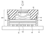
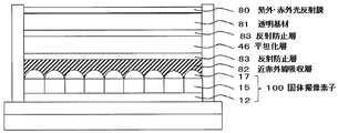
- FIG. 1 is a schematic sectional view of a solid-state imaging device according to an embodiment of the present invention. It is a schematic sectional drawing which shows an example of the near-infrared cut filter periphery part in a camera module. It is a schematic sectional drawing which shows an example of the near-infrared cut filter periphery part in a camera module. It is a schematic sectional drawing which shows an example of the near-infrared cut filter periphery part in a camera module. It is a figure which shows the spectral transmittance of the cured film of this invention.
- the organic EL element in the present invention refers to an organic electroluminescence element.
- (meth) acrylate” represents acrylate and methacrylate
- (meth) acryl represents acryl and methacryl
- (meth) acryloyl represents acryloyl and methacryloyl.
- “monomer” and “monomer” are synonymous.
- the monomer in the present invention is distinguished from an oligomer and a polymer and refers to a compound having a weight average molecular weight of 2,000 or less.
- a weight average molecular weight and dispersion degree are defined as a polystyrene conversion value by GPC measurement.
- the weight average molecular weight (Mw) and the number average molecular weight (Mn) of the curable compound (B) are, for example, HLC-8120 (manufactured by Tosoh Corporation), and TSK gel Multipore HXL as a column.
- the polymerizable compound means a compound having a polymerizable functional group, and may be a monomer or a polymer.
- the polymerizable functional group refers to a group that participates in a polymerization reaction.
- the description which does not describe substitution and unsubstituted includes what has a substituent with what does not have a substituent.
- the near infrared ray in the present invention refers to one having a maximum absorption wavelength ( ⁇ max) region of 700 to 1000 nm.
- the curable composition of the present invention includes a near-infrared absorbing dye (A), a fluorine atom, a silicon atom, a linear alkyl group having 8 or more carbon atoms, and carbon.
- a curable compound (B) having one or more selected from a branched alkyl group of several or more is included, or a curable compound (B) having a hydrophobic group.
- ADVANTAGE OF THE INVENTION According to this invention, even when immersed in a solvent, the curable composition from which the cured film which a near-infrared absorptive pigment
- the curable composition has at least one selected from a fluorine atom, a silicon atom, a linear alkyl group having 8 or more carbon atoms and a branched alkyl group having 3 or more carbon atoms.
- the curable compound (B) tends to be unevenly distributed on the surface side far from the substrate. It is in.
- a region where the ratio of the cured product of the curable compound (B) is large is formed on the surface far from the substrate. . If such a region exists, it is considered that the near-infrared absorbing dye (A) can be prevented from leaching from the film surface even when the cured film is immersed in a solvent.
- the near-infrared absorbing dye (A) used in the present invention is preferably a substance having a maximum absorption wavelength region of 700 to 1000 nm, more preferably 800 to 900 nm.
- the near-infrared absorbing substance may contain only one type or two or more types.
- the molar extinction coefficient ⁇ of the near-infrared absorbing dye is not particularly limited, but is preferably 50,000 to 500,000, more preferably 100,000 to 300,000.
- a near infrared absorbing dye having a hydrophobic group can also be used. Even when a near-infrared absorbing dye having a hydrophobic group is used, by mixing the curable compound (B) in the composition of the present invention, the curable compound (B) is on the surface side far from the substrate. Since a region with a high proportion of the cured product of the curable compound (B) is formed on the surface far from the substrate, the cured film using a near infrared absorbing dye having a hydrophobic group is immersed in a solvent. Even if it makes it, it is thought that it can suppress that this near-infrared absorptive dye oozes from the film
- the near-infrared absorbing dye preferably has a portion having a CLogP value of 5.3 or more (hereinafter referred to as substituent R) as a hydrophobic group, and more preferably has a substituent R at a terminal portion in the molecule. preferable.
- substituent R a CLogP value of 5.3 or more
- the CLogP value is calculated according to Chem. A value calculated by replacing a substituent group with a hydrogen atom using Draw software (Version 2.0).
- the near infrared absorbing dye can be more uniformly dispersed in the film by using together the curable compound (B) that tends to be unevenly distributed on the surface.
- the CLogP value of the substituent R is preferably 6 or more, more preferably 9 or more, and still more preferably 10 or more.
- the upper limit of the CLogP value of the substituent R is not particularly limited, but is preferably 20 or less.
- the substituent R preferably has a hydrocarbon group, and more preferably has an alkyl group.
- the alkyl group is preferably linear or branched, and more preferably branched.
- the number of carbon atoms in the alkyl group is preferably 3 or more, more preferably 8 or more, still more preferably 16 or more, and particularly preferably 20 or more.
- the upper limit of the carbon number of the alkyl group is not particularly limited, but is preferably 30 or less, and more preferably 25 or less.
- the near-infrared absorbing dye preferably has one or more substituents R, more preferably two or more.
- the upper limit of the number of substituents R is not particularly limited, but is preferably 4 or less, and more preferably 3 or less.
- the near-infrared absorbing dye may have only one type of substituent R, or may have two or more types. Examples of the substituent R in which the CLogP value satisfies the above range include the following, but are not limited thereto.
- Examples of near infrared absorbing dyes include pyrrolopyrrole dyes, copper compounds, cyanine dyes, phthalocyanine compounds, imonium compounds, thiol complex compounds, transition metal oxide compounds, squarylium dyes, naphthalocyanine dyes, Examples include quatarylene dyes, dithiol metal complex dyes, and croconium compounds.
- dye As a near-infrared absorptive pigment
- Formula (A1) In formula (A1), R 1a and R 1b each independently represent a substituent having an alkyl group, an aryl group, or a heteroaryl group. R 2 and R 3 each independently represents a hydrogen atom or a substituent, at least one of which is an electron-withdrawing group, and R 2 and R 3 may be bonded to each other to form a ring.
- R 4 represents a hydrogen atom, an alkyl group, an aryl group, a heteroaryl group, a substituted boron or a metal atom, and may be covalently or coordinately bonded to at least one of R 1a , R 1b and R 3 .
- the number of carbon atoms of the alkyl group contained in the substituents represented by R 1a and R 1b is preferably 1 or more, more preferably 3 or more, still more preferably 8 or more, and particularly preferably 16 or more.
- the upper limit of the carbon number of the alkyl group is preferably 30 or less, more preferably 25 or less, can be 20 or less, and can be 10 or less.
- the aryl group contained in the substituent represented by R 1a or R 1b preferably has 6 to 30 carbon atoms, more preferably 6 to 20 carbon atoms, and still more preferably 6 to 12 carbon atoms.
- the carbon number of the heteroaryl group contained in the substituent represented by R 1a or R 1b is preferably 6 to 30, and more preferably 6 to 12.
- the hetero atom include a nitrogen atom, an oxygen atom, and a sulfur atom.
- the preferred range of the CLogP value of the alkyl group, aryl group or heteroaryl group contained in R 1a and R 1b is the same as that of the substituent R described above.
- the substituent represented by R 1a or R 1b is preferably an aryl group having an alkoxy group having a branched alkyl group.
- the number of carbon atoms of the alkyl group in the branched alkyl group is preferably 3 or more, more preferably 8 or more, and still more preferably 16 or more.
- the upper limit of the carbon number of the branched alkyl group is preferably 30 or less, more preferably 25 or less, and can also be 20 or less.
- R 1a and R 1b for example, 4- (2-ethylhexyloxy) phenyl, 4- (2-methylbutyloxy) phenyl, and 4- (2-octyldodecyloxy) phenyl are particularly preferable.
- R 1a and R 1b in the general formula (A1) may be the same as or different from each other.
- R 2 and R 3 each independently represent a hydrogen atom or a substituent T, at least one of which is an electron-withdrawing group, and R 2 and R 3 may be bonded to form a ring.
- R 2 and R 3 each independently represent a cyano group or a heterocyclic group.
- substituent T include the following.
- Alkyl group (preferably 1 to 30 carbon atoms), alkenyl group (preferably 2 to 30 carbon atoms), alkynyl group (preferably 2 to 30 carbon atoms), aryl group (preferably 6 to 30 carbon atoms), amino group (Preferably 0 to 30 carbon atoms), alkoxy group (preferably 1 to 30 carbon atoms), aryloxy group (preferably 6 to 30 carbon atoms), aromatic heterocyclic oxy group (preferably 1 to 30 carbon atoms)
- An acyl group (preferably 1 to 30 carbon atoms), an alkoxycarbonyl group (preferably 2 to 30 carbon atoms), an aryloxycarbonyl group (preferably 7 to 30 carbon atoms), an acyloxy group (preferably 2 to 30 carbon atoms).
- Acylamino group (preferably having 2 to 30 carbon atoms), alkoxycarbonylamino group (preferably having 2 to 30 carbon atoms), aryloxycarbonylamino group Preferably 7 to 30 carbon atoms, sulfonylamino group (preferably 1 to 30 carbon atoms), sulfamoyl group (preferably 0 to 30 carbon atoms), carbamoyl group (preferably 1 to 30 carbon atoms), alkylthio group (preferably Is an arylthio group (preferably 6 to 30 carbon atoms), an aromatic heterocyclic thio group (preferably 1 to 30 carbon atoms), a sulfonyl group (preferably 1 to 30 carbon atoms), a sulfinyl group (Preferably 1 to 30 carbon atoms), ureido group (preferably 1 to 30 carbon atoms), phosphoric acid amide group (preferably 1 to 30 carbon atoms), hydroxy group, mercapto group, halogen atom, cyan
- At least one of R 2 and R 3 is an electron withdrawing group.
- a substituent having a positive Hammett ⁇ p value usually acts as an electron-withdrawing group.
- Preferred examples of the electron withdrawing group include a cyano group, an acyl group, an alkyloxycarbonyl group, an aryloxycarbonyl group, a sulfamoyl group, a sulfinyl group, a heterocyclic group, and the like, and a cyano group is more preferable. These electron withdrawing groups may be further substituted.
- a substituent having Hammett's substituent constant ⁇ p value of 0.2 or more can be exemplified as an electron withdrawing group.
- the ⁇ p value is preferably 0.25 or more, more preferably 0.3 or more, and particularly preferably 0.35 or more.
- the upper limit is not particularly limited, but is preferably 0.80. Specific examples include cyano group (0.66), carboxyl group (—COOH: 0.45), alkoxycarbonyl group (—COOMe: 0.45), aryloxycarbonyl group (—COOPh: 0.44), carbamoyl.
- R 2 and R 3 are bonded to each other to form a ring, it is preferable to form a 5- to 7-membered ring (preferably a 5- or 6-membered ring).
- the ring formed is preferably a merocyanine dye that is used as an acidic nucleus, and specific examples thereof can include, for example, paragraphs 0019 to 0021 of JP 2011-68731 A, the contents of which are incorporated herein. It is.
- R 3 is particularly preferably a heterocycle.
- R 3 is preferably quinoline, benzothiazole or naphthothiazole.
- Two R 2 s in formula (A1) may be the same as or different from each other, and two R 3 s may be the same as or different from each other.
- R 4 When the group represented by R 4 is an alkyl group, an aryl group, or a heteroaryl group, this group has the same meaning as described for R 1a and R 1b , and preferred groups are also the same.
- the group represented by R 4 When the group represented by R 4 is substituted boron, the substituent has the same meaning as the substituent T described above for R 2 and R 3 , and is preferably an alkyl group, an aryl group, or a heteroaryl group.
- the group represented by R 4 When the group represented by R 4 is a metal atom, it is preferably a transition metal, particularly preferably a substituted boron.
- R 4 may be covalently bonded or coordinated to at least one of R 1a , R 1b and R 3 , and it is particularly preferable that R 4 is coordinated to R 3 .
- R 4 is preferably a hydrogen atom or a substituted boron (particularly diphenyl boron).
- Two R 4 s in the formula (A1) may be the same as or different from each other.
- each R 10 independently represents a hydrogen atom, an alkyl group, an aryl group, a heteroaryl group, a substituted boron or a metal atom, and may be covalently or coordinately bonded to R 12 .
- R 11 and R 12 each independently represents a hydrogen atom or a substituent, at least one of which is an electron-withdrawing group, and R 11 and R 12 may combine to form a ring.
- R 13 each independently represents a branched alkyl group having 3 to 30 carbon atoms.
- R 10 has the same meaning as R 4 in formula (A1), and the preferred range is also the same.
- R 11 and R 12 have the same meanings as R 2 and R 3 in the above (A1), and preferred ranges are also the same.
- R 13 may be the same as or different from each other.
- the number of carbon atoms of R 13 has the same meaning as the branched alkyl group described for R 1a and R 1b in formula (A1) described above, and the preferred range is also the same.
- a preferable range of the CLogP value of R 13 is the same as that of the substituent R described above.
- R 13 is preferably an alcohol residue derived from, for example, isoeicosanol (manufactured by Nissan Chemical Co., Ltd., Fineoxocol 2000).
- the alcohol may be linear or branched, preferably an alcohol having 1 to 30 carbon atoms, more preferably an alcohol having 3 to 25 carbon atoms, and particularly preferably a branched alcohol having 3 to 25 carbon atoms. More specifically, methanol, ethanol, iso-propanol, n-butanol, tert-butanol, 1-octanol, 1-decanol, 1-hexadecanol, 2-methylbutanol, 2-ethylhexanol, 2-octyldodeca Nord, isohexadecanol (Nissan Chemical Co., Ltd., Fineoxocol 1600), isooctadecanol (Nissan Chemical Co., Ltd., Fineoxocol 180), isooctadecanol (Nissan Chemical Co., Ltd., Fineoxocol) 180N), isooctadecanol (manufactured by Nissan Chemical Co.,
- each R 20 independently represents a branched alkyl group having 3 to 30 carbon atoms.
- R 20 has the same meaning as R 13 in formula (A2), and the preferred range is also the same.
- a copper compound is also preferable as the near-infrared absorbing dye (A).
- the ligand L that coordinates to copper is not particularly limited as long as it can be coordinated to a copper ion.
- sulfonic acid carboxylic acid, phosphoric acid, phosphate ester , Phosphonic acid, phosphonic acid ester, phosphinic acid, substituted phosphinic acid, carbonyl (ester, ketone), amine, amide, sulfonamide, urethane, urea, alcohol, thiol and the like.
- carboxylic acid and sulfonic acid are preferable, and sulfonic acid is more preferable.
- Specific examples of the copper complex include a phosphorus-containing copper compound, a sulfonic acid copper compound, or a copper compound represented by the following formula.
- Specific examples of the phosphorus-containing copper compound may include compounds described in WO 2005/030898, page 5, line 27 to page 7, line 20; Incorporated in the description.
- the copper complex represented by a following formula (A4) is mentioned, for example.
- Cu (L) n1 ⁇ (X) n2 formula (A4) L represents a ligand coordinated to copper, and X does not exist or is a halogen atom, H 2 O, NO 3 , ClO 4 , SO 4 , CN, SCN, or BF 4. , PF 6 , BPh 4 (Ph represents a phenyl group) or alcohol.
- n1 and n2 each independently represents an integer of 1 to 4.
- the ligand L has a substituent containing C, N, O, and S as atoms capable of coordinating to copper, and more preferably has a group having a lone pair such as N, O, and S It is.
- the group capable of coordinating is not limited to one type in the molecule and may include two or more types, and may be dissociated or non-dissociated.
- the preferred ligand L has the same meaning as the ligand L described above. In the case of non-dissociation, X is not present.
- the copper complex has a form in which a ligand is coordinated to copper as a central metal. Copper in the copper complex is usually divalent copper, and can be obtained, for example, by mixing and reacting a compound serving as a ligand or a salt thereof with a copper component.
- the compound serving as the ligand is preferably a compound having a coordination site, and is preferably a compound represented by the following general formula (A5).
- X 1 represents a coordination site
- n3 represents an integer of 1 to 6
- R 1 represents a single bond or an n-valent group.
- X 1 is preferably a coordination site coordinated by an anion or a coordination site coordinated by a lone pair.
- the anion should just be coordinated to the copper atom in a copper component, and an oxygen anion, a nitrogen anion, or a sulfur anion is preferable.
- the coordination site coordinated with an anion is preferably at least one selected from the following group (AN).
- Group (AN) is preferably at least one selected from the following group (AN).
- X represents N or CR, and each R independently represents a hydrogen atom, an alkyl group, an alkenyl group, an alkynyl group, an aryl group or a heteroaryl group.
- the alkyl group may be linear, branched or cyclic, but is preferably linear.
- the alkyl group preferably has 1 to 10 carbon atoms, more preferably 1 to 6 carbon atoms, and still more preferably 1 to 4 carbon atoms. Examples of the alkyl group include a methyl group.
- the alkyl group may have a substituent, and examples of the substituent include a halogen atom, a carboxyl group, and a heterocyclic group.
- the heterocyclic group as a substituent may be monocyclic or polycyclic, and may be aromatic or non-aromatic.
- the number of heteroatoms constituting the heterocycle is preferably 1 to 3, and preferably 1 or 2.
- the hetero atom constituting the hetero ring is preferably a nitrogen atom.
- the alkyl group has a substituent, it may further have a substituent.
- the alkenyl group preferably has 1 to 10 carbon atoms, and more preferably 1 to 6 carbon atoms.
- the alkynyl group preferably has 1 to 10 carbon atoms, and more preferably 1 to 6 carbon atoms.
- the aryl group may be monocyclic or polycyclic, but is preferably monocyclic.
- the aryl group preferably has 6 to 18 carbon atoms, more preferably 6 to 12 carbon atoms, and still more preferably 6 carbon atoms.
- the heteroaryl group may be monocyclic or polycyclic.
- the number of heteroatoms constituting the heteroaryl group is preferably 1 to 3.
- the hetero atom constituting the heteroaryl group is preferably a nitrogen atom, a sulfur atom or an oxygen atom.
- the heteroaryl group preferably has 6 to 18 carbon atoms, more preferably 6 to 12 carbon atoms.
- Examples of coordination sites coordinated by anions also include monoanionic coordination sites.
- part represents the site
- an acid group phosphoric acid diester group, phosphonic acid monoester group, phosphinic acid group, etc.
- a phosphorus atom, a sulfo group, a carboxyl group, a hydroxyl group and the like can be mentioned.
- the coordination site coordinated by the lone pair preferably includes an oxygen atom, a nitrogen atom, a sulfur atom or a phosphorus atom as a coordination atom coordinated by the lone pair, and the oxygen atom, nitrogen atom or sulfur More preferably, it contains an atom, and even more preferably a nitrogen atom.
- the coordination site coordinated by the lone pair is preferably a ring containing a coordination atom coordinated by the lone pair or a partial structure selected from the following group (UE).
- the ring containing a coordinating atom coordinated by a lone pair may be monocyclic or polycyclic, and may be aromatic or non-aromatic.
- the ring containing a coordinating atom coordinated by a lone pair may have a substituent, such as an alkyl group, aryl group, halogen atom, silicon atom, alkoxy group, acyl group, alkylthio group. And carboxyl group.
- the ring may further have a substituent.
- R and R 1 each independently represent a hydrogen atom, an alkyl group, an alkenyl group, an alkynyl group, an aryl group or a heteroaryl group
- R 2 each independently represent a hydrogen atom or an alkyl group.
- the alkyl group represented by R, R 1 and R 2 in the group (UE) has the same meaning as the alkyl group described in the group (AN), and the preferred range is also the same.
- the alkenyl group represented by R, R 1 and R 2 in the group (UE) is synonymous with the alkenyl group described in the group (AN), and the preferred range is also the same.
- the alkynyl group represented by R, R 1 and R 2 in the group (UE) is synonymous with the alkynyl group described in the group (AN), and the preferred range is also the same.
- the aryl group represented by R, R 1 and R 2 in the group (UE) has the same meaning as the aryl group described in the group (AN), and the preferred range is also the same.
- the heteroaryl group represented by R, R 1 and R 2 in the group (UE) has the same meaning as the heteroaryl group described in the group (AN), and the preferred range is also the same.
- the number of carbon atoms of the alkoxy group represented by R 2 in the group (UE) is preferably 1 to 12, and more preferably 3 to 9.
- the number of carbon atoms of the aryloxy group represented by R 2 in the group (UE) is preferably 6 to 18, and more preferably 6 to 12.
- the heteroaryloxy group represented by R 2 in the group (UE) may be monocyclic or polycyclic.
- the heteroaryl group which comprises heteroaryloxy group is synonymous with the heteroaryl group demonstrated in the said group (AN), and its preferable range is also the same.
- the number of carbon atoms of the alkylthio group represented by R 2 in the group (UE) is preferably 1 to 12, and more preferably 1 to 9.
- the number of carbon atoms of the arylthio group represented by R 2 in the group (UE) is preferably 6 to 18, and more preferably 6 to 12.
- the heteroarylthio group represented by R 2 in the group (UE) may be monocyclic or polycyclic.
- the heteroaryl group which comprises a heteroarylthio group is synonymous with the heteroaryl group demonstrated in the said group (AN), and its preferable range is also the same.
- the number of carbon atoms of the acyl group represented by R 2 in the group (UE) is preferably 2 to 12, and more preferably 2 to 9.
- X 1 may be an acid group, and is preferably at least one selected from a sulfonic acid group, a carboxylic acid group and an acid group containing a phosphorus atom.
- X 1 may be one kind or two or more kinds, but preferably two or more kinds, and those having a sulfonic acid group and a carboxylic acid group are preferred.
- n3 is preferably 1 to 3, more preferably 2 or 3, and still more preferably 3.
- the n-valent group is an n-valent organic group, or an n-valent organic group, and —O—, —SO—, —SO 2 —, —NR N1 —, —CO—, A group consisting of a combination with -CS- is preferred.
- the n-valent organic group include a hydrocarbon group, an oxyalkylene group, and a heterocyclic group.
- the n-valent group is selected from a group containing at least one selected from the group (AN-1), a ring containing a coordination atom coordinated by an unshared electron pair, or the group (UE-1) It may be a group containing at least one selected from the above.
- the hydrocarbon group is preferably an aliphatic hydrocarbon group or an aromatic hydrocarbon group.
- the hydrocarbon group may have a substituent.
- substituents include an alkyl group, a halogen atom (preferably a fluorine atom), a polymerizable group (for example, a vinyl group, a (meth) acryloyl group, an epoxy group, Oxetane groups, etc.), sulfonic acid groups, carboxylic acid groups, acid groups containing phosphorus atoms, carboxylic acid ester groups (eg —CO 2 CH 3 ), hydroxyl groups, alkoxy groups (eg methoxy groups), amino groups, carbamoyl groups, Examples thereof include a carbamoyloxy group, a halogenated alkyl group (for example, a fluoroalkyl group and a chloroalkyl group), a (meth) acryloyloxy group, and the like.
- the hydrocarbon group may further have a substituent, and examples of the substituent include an alkyl group, the polymerizable group, and a halogen atom.
- the hydrocarbon group is monovalent, an alkyl group, an alkenyl group or an aryl group is preferable, and an aryl group is more preferable.
- the hydrocarbon group is divalent, an alkylene group, an arylene group, or an oxyalkylene group is preferable, and an arylene group is more preferable.
- the hydrocarbon group is trivalent or higher, those corresponding to the monovalent hydrocarbon group or divalent hydrocarbon group are preferred.
- the alkyl group and the alkylene group may be linear, branched or cyclic.
- the carbon number of the linear alkyl group and alkylene group is preferably 1-20, more preferably 1-12, and even more preferably 1-8.
- the branched alkyl group and alkylene group preferably have 3 to 20 carbon atoms, more preferably 3 to 12 carbon atoms, and still more preferably 3 to 8 carbon atoms.
- the cyclic alkyl group and alkylene group may be monocyclic or polycyclic.
- the number of carbon atoms in the cyclic alkyl group and the alkylene group is preferably 3 to 20, more preferably 4 to 10, and still more preferably 6 to 10.
- the alkenyl group and alkenylene group preferably have 2 to 10 carbon atoms, more preferably 2 to 8 carbon atoms, and still more preferably 2 to 4 carbon atoms.
- the number of carbon atoms in the aryl group and arylene group is preferably 6 to 18, more preferably 6 to 14, and still more preferably 6 to 10.
- the heterocyclic group includes an alicyclic group having a hetero atom or an aromatic heterocyclic group.
- the heterocyclic group is preferably a 5-membered ring or a 6-membered ring.
- the heterocyclic group is a single ring or a condensed ring, preferably a single ring or a condensed ring having 2 to 8 condensations, and more preferably a single ring or a condensed ring having 2 to 4 condensations.
- the heterocyclic group may have a substituent, and the substituent is synonymous with the substituent that the hydrocarbon group described above may have.
- R N1 represents a hydrogen atom, an alkyl group, an aryl group or an aralkyl group.
- the alkyl group in R N1 may be any of a chain, a branch, and a ring.
- the linear or branched alkyl group preferably has 1 to 20 carbon atoms, and more preferably 1 to 12 carbon atoms.
- the cyclic alkyl group may be monocyclic or polycyclic.
- the cyclic alkyl group preferably has 3 to 20 carbon atoms, and more preferably 4 to 14 carbon atoms.
- the carbon number of the aryl group in R N1 is preferably 6 to 18, and more preferably 6 to 14. Specifically, a phenyl group, a naphthyl group, etc. are illustrated.
- X represents N or CR, and each R independently represents a hydrogen atom, an alkyl group, an alkenyl group, an alkynyl group, an aryl group or a heteroaryl group, It is synonymous with X in the parenthesis, and a preferable range is also the same.
- each R independently represents a hydrogen atom, an alkyl group, an alkenyl group, an alkynyl group, an aryl group or a heteroaryl group, and has the same meaning as R in the group (UE) described above,
- the preferable range is also the same.
- the compound containing an acid group or its salt is also preferable, for example, an organic acid compound (For example, a sulfonic acid compound, a carboxylic acid compound, a phosphoric acid compound) Or the salt etc. are mentioned suitably.
- the molecular weight of the compound serving as the ligand or a salt thereof is preferably 80 or more, and the upper limit is preferably 1000 or less, more preferably 750 or less, and even more preferably 600 or less.
- the sulfonic acid copper complex has copper as a central metal and a sulfonic acid compound as a ligand.
- a compound represented by the following general formula (A6) is preferable.
- R 2 represents a monovalent organic group.
- the compound represented by the general formula (A6) or a salt thereof acts as a ligand coordinated to copper.
- Specific examples of the monovalent organic group represented by R 2 in the general formula (A6) include a hydrocarbon group, specifically, a linear, branched, or cyclic alkyl group, alkenyl group, An aryl group etc. can be mentioned.
- these groups are divalent linking groups (for example, linear or branched alkylene groups, cyclic alkylene groups (cycloalkylene groups), arylene groups, —O—, —S—, —CO—. , —C ( ⁇ O) O—, —OCO—, —SO 2 —, —NR— (wherein R is a hydrogen atom or an alkyl group) and the like.
- R is a hydrogen atom or an alkyl group
- the carbon number of the linear alkyl group, the branched alkyl group, the cyclic alkyl group, the alkenyl group, and the aryl group is the same as that described for R 1 in the above general formula (A5), and the preferred range is also the same It is.
- the monovalent organic group may have a substituent.
- Examples of the substituent that the monovalent organic group may have include an alkyl group, a polymerizable group (for example, a vinyl group, a (meth) acryloyl group, an epoxy group, and an oxetane group), a halogen atom, a carboxyl group, and a carboxyl group.
- Examples include acid ester groups (for example, —CO 2 CH 3 and the like), hydroxyl groups, amide groups, halogenated alkyl groups (for example, fluoroalkyl groups and chloroalkyl groups), and the like.
- linear or branched alkylene group cyclic alkylene group or arylene group which is a divalent linking group
- one hydrogen atom is removed from the above-mentioned linear, branched or cyclic alkyl group or aryl group.
- a divalent linking group derived from the above.
- the molecular weight of the compound represented by the general formula (A6) is preferably 80 to 750, more preferably 80 to 600, and still more preferably 80 to 450. Specific examples of the compound represented by the general formula (A6) are shown below, but are not limited thereto.
- the copper sulfonate complex can be obtained by reacting a copper component with a sulfonic acid compound or a salt thereof as a ligand.
- a copper component copper or a compound containing copper can be used.
- the compound containing copper for example, copper oxide or a copper salt can be used.
- the copper salt is preferably monovalent or divalent copper, and more preferably divalent copper.
- Copper salts include copper acetate, copper chloride, copper formate, copper stearate, copper benzoate, copper ethyl acetoacetate, copper pyrophosphate, copper naphthenate, copper citrate, copper nitrate, copper sulfate, copper carbonate, copper chlorate Copper (meth) acrylate and copper perchlorate are more preferable, and copper acetate, copper chloride, copper sulfate, copper benzoate, and copper (meth) acrylate are more preferable.
- the sulfonic acid compound that can be used in the present invention can be a commercially available sulfonic acid, or can be synthesized by referring to a known method.
- a salt of the sulfonic acid compound that can be used in the present invention for example, a metal salt is preferable, and specific examples thereof include a sodium salt and a potassium salt.
- a copper compound having a carboxylic acid as a ligand may be used in addition to those described above.
- a carboxylic acid used for a copper compound having a carboxylic acid as a ligand for example, a compound represented by the following general formula (A7) is preferable.
- R 4 represents a monovalent organic group.
- the monovalent organic group is not particularly limited, there monovalent synonymous with organic radicals R 2 of in general formula (A6), it is also the preferred ranges thereof.
- a copper compound having a phosphate ester as a ligand can also be used.
- JP-A-2013-253224, paragraphs 0015 to 0027 can be referred to as the phosphoric acid ester compound used for the phosphoric acid ester copper compound, the contents of which are incorporated herein.
- a copper compound obtained by a reaction between a polymer containing an acid group or a salt thereof and a copper component can be used.
- This copper compound is, for example, a polymer containing an acid group ion site and a polymer type copper compound containing copper ion, and a preferred embodiment is a polymer type copper compound having an acid group ion site in the polymer as a ligand.
- This polymer-type copper compound usually has an acid group ion site in the side chain of the polymer, the acid group ion site is bonded to copper (for example, coordinate bond), and copper is the starting point between the side chains. A crosslinked structure is formed.
- Polymer-type copper compounds include polymer copper complexes having a carbon-carbon bond in the main chain, polymer copper complexes having a carbon-carbon bond in the main chain, and a copper complex containing a fluorine atom, main chain And a copper complex of a polymer having an aromatic hydrocarbon group and / or an aromatic heterocyclic group (hereinafter referred to as an aromatic group-containing polymer).
- the copper component a compound containing divalent copper is preferable.
- the copper content in the copper component is preferably 2 to 40% by mass, more preferably 5 to 40% by mass.
- a copper component may use only 1 type and may use 2 or more types.
- the compound containing copper for example, copper oxide or a copper salt can be used.
- the copper salt is more preferably divalent copper.
- copper salt copper hydroxide, copper acetate, and copper sulfate are particularly preferable.
- the acid group possessed by the polymer containing an acid group or a salt thereof is not particularly limited as long as it can react with the copper component described above, but is preferably one that coordinates with the copper component.
- Specific examples include acid groups having an acid dissociation constant (pKa) of 12 or less, and sulfonic acid groups, carboxylic acid groups, phosphoric acid groups, phosphonic acid groups, phosphinic acid groups, imidoic acid groups, and the like are preferable. Only one type of acid group may be used, or two or more types may be used.
- Examples of the atom or atomic group constituting the salt of the acid group used in the present invention include a metal atom such as sodium (particularly an alkali metal atom), an atomic group such as tetrabutylammonium.
- the acid group or a salt thereof may be contained in at least one of the main chain and the side chain, and is preferably contained in at least the side chain.
- the polymer containing an acid group or a salt thereof is preferably a polymer containing a carboxylic acid group or a salt thereof and / or a sulfonic acid group or a salt thereof, and more preferably a polymer containing a sulfonic acid group or a salt thereof.
- a preferred example of the polymer containing an acid group or a salt thereof is a structure in which the main chain has a carbon-carbon bond, and preferably contains a structural unit represented by the following formula (A8).
- R 1 represents a hydrogen atom or a methyl group
- L 1 represents a single bond or a divalent linking group
- M 1 represents a hydrogen atom, or an atom or atom constituting a salt with a sulfonic acid group Represents a group.
- R 1 is preferably a hydrogen atom.
- the divalent linking group is not particularly limited, but examples thereof include a divalent hydrocarbon group, a heteroarylene group, —O—, — S—, —CO—, —COO—, —OCO—, —SO 2 —, —NX— (X represents a hydrogen atom or an alkyl group, preferably a hydrogen atom), or a group consisting of a combination thereof. It is done.
- the divalent hydrocarbon group include a linear, branched or cyclic alkylene group and an arylene group. The hydrocarbon group may have a substituent, but is preferably unsubstituted.
- the linear alkylene group preferably has 1 to 30 carbon atoms, more preferably 1 to 15 carbon atoms, and still more preferably 1 to 6 carbon atoms.
- the number of carbon atoms of the branched alkylene group is preferably 3 to 30, more preferably 3 to 15, and still more preferably 3 to 6.
- the cyclic alkylene group may be monocyclic or polycyclic.
- the number of carbon atoms of the cyclic alkylene group is preferably 3 to 20, more preferably 4 to 10, and still more preferably 6 to 10.
- the number of carbon atoms of the arylene group is preferably 6 to 18, more preferably 6 to 14, still more preferably 6 to 10, and particularly preferably a phenylene group.
- a 5-membered ring or a 6-membered ring is preferable.
- the heteroarylene group may be a single ring or a condensed ring, and is preferably a single ring or a condensed ring having 2 to 8 condensations, and more preferably a single ring or a condensed ring having 2 to 4 condensations.
- the atom or atomic group constituting the salt with the sulfonic acid group represented by M 1 is synonymous with the atom or atomic group constituting the salt of the acid group described above, and is a hydrogen atom or an alkali metal. An atom is preferred.
- Y 2 is preferably a group consisting of —COO—, —CO—, —NH—, a linear or branched alkylene group, or a combination thereof, or a single bond.
- X 2 represents —PO 3 H, —PO 3 H 2 , —OH or COOH, and is preferably —COOH.
- the polymer (A8) contains another structural unit (preferably a structural unit represented by the above formula (A9)), it is represented by the structural unit represented by the above formula (A8) and the above formula (A9).
- the molar ratio of the structural units is preferably 95: 5 to 20:80, more preferably 90:10 to 40:60.
- ⁇ Polymer containing second acid group or salt thereof >>> Moreover, as a copper compound which can be used by this invention, you may use the copper compound obtained by reaction with an acid group or its salt, the polymer which further contains a fluorine atom, and a copper component.
- a polymer containing an acid group or a salt thereof and a fluorine atom is reacted with a copper component, for example, a polymer containing an acid group ion site and a fluorine atom and a polymer type copper compound containing a copper ion are obtained.
- a copper component it is synonymous with the compound obtained by reaction of the polymer containing the acid group or its salt mentioned above, and a copper component, and its preferable range is also the same.
- a preferred example of the polymer containing an acid group or a salt thereof and a fluorine atom includes a structural unit represented by at least one of the following formulas (A10-1), (A10-2) and (A10-3) Is preferred.
- R 1 represents an aliphatic hydrocarbon group
- Y 1 represents a single bond or a divalent linking group
- X 1 represents an acid group or a salt thereof
- R 1 and Y 1 At least one is substituted with a fluorine atom.
- R 2 represents an aliphatic hydrocarbon group
- R 3 represents a hydrocarbon group
- Y 2 represents a single bond or a divalent linking group
- R 2 , R 3 and Y 2 At least one of is substituted with a fluorine atom.
- Ar 1 represents an aromatic hydrocarbon group and / or an aromatic heterocyclic group
- R 4 represents an organic group
- Y 3 represents a single bond or a divalent linking group
- X 2 represents an acid group or a salt thereof, and at least one of Ar 1 , R 4 and Y 3 is substituted with a fluorine atom.
- R 1 and R 2 each independently represents an aliphatic hydrocarbon group, and examples thereof include a linear, branched or cyclic alkyl group.
- the number of carbon atoms of the linear alkyl group is preferably 1-20, more preferably 1-10, and even more preferably 1-6.
- the carbon number of the branched alkyl group is preferably 3 to 20, more preferably 3 to 10, and further preferably 3 to 6.
- the cyclic alkyl group may be monocyclic or polycyclic.
- the number of carbon atoms in the cyclic alkyl group is preferably 3 to 20, more preferably 4 to 10, and still more preferably 6 to 10.
- R 1 and R 2 have a substituent
- the substituent is not particularly limited, and examples thereof include a polymerizable group (preferably a polymerizable group containing a carbon-carbon double bond), a halogen atom (fluorine Atom, chlorine atom, bromine atom, iodine atom), alkyl group, carboxylic ester group, halogenated alkyl group, alkoxy group, methacryloyloxy group, acryloyloxy group, ether group, sulfonyl group, sulfide group, amide group, acyl group , A hydroxy group, a carboxyl group, an aralkyl group, —Si— (OR N22 ) 3 and the like, and a fluorine atom is particularly preferable.
- R N22 represents an alkyl group, preferably having 1 to 3 carbon atoms.
- the divalent linking group is 2 in the above formula (A8).
- the hydrocarbon group include a linear, branched or cyclic alkylene group and an arylene group.
- the number of carbon atoms in the linear alkylene group is preferably 1-20, more preferably 1-10, and even more preferably 1-6.
- the carbon number of the branched alkylene group is preferably 3 to 20, more preferably 3 to 10, and further preferably 3 to 6.
- the cyclic alkylene group may be monocyclic or polycyclic.
- the number of carbon atoms of the cyclic alkylene group is preferably 3 to 20, more preferably 4 to 10, and still more preferably 6 to 10.
- the arylene group and the heteroarylene group have the same meaning as the case where the divalent linking group in the above-described formula (A6) is an arylene group.
- Y 1 represents a divalent linking group, —COO—, —CO—, —O—, —NX—
- X represents a hydrogen atom or an alkyl group, preferably a hydrogen atom
- a hydrocarbon group A group consisting of an alkylene group having 1 to 30 carbon atoms or an arylene group) or a combination thereof is preferable.
- X 1 and X 2 each independently represent an acid group or a salt thereof, and are synonymous with the above-described acid group or a salt thereof, and preferred ranges are also the same is there.
- R 1 and Y 1 are substituted with a fluorine atom.
- Y 1 is substituted with a fluorine atom, for example, that at least one of hydrogen atoms constituting R 1 is substituted with a fluorine atom. It is preferable that at least one of R 1 and Y 1 is a perfluoro group. Of R 1 and Y 1 , Y 1 is preferably substituted with a fluorine atom.
- R 3 represents a hydrocarbon group, and examples thereof include the alkyl group and aryl group described for R 1 in formula (A10-1).
- the alkyl group has the same meaning as the alkyl group described for R 1 in formula (A10-1), and the preferred range is also the same.
- the number of carbon atoms in the aryl group is preferably 6 to 18, more preferably 6 to 14, and more preferably 6 to 10.
- R 3 has a substituent, the substituent is not particularly limited, but a fluorine atom is preferable.
- at least one of R 2, R 3 and Y 2 is a fluorine atom, it is preferred that R 2, R 3 and Y 2 at least one of a perfluoroalkyl group.
- Ar 1 preferably represents an aromatic hydrocarbon group.
- the aromatic hydrocarbon group an aryl group having 6 to 20 carbon atoms is preferable, and a phenyl group or a biphenyl group is more preferable.
- the aromatic heterocyclic group is not particularly limited, and for example, an aromatic heterocyclic group having 2 to 30 carbon atoms can be used.
- R 4 represents an organic group, an alkylene group having 1 to 6 carbon atoms, a cycloalkylene group having 1 to 6 carbon atoms, —O—, —SO 2 —, —CO—, —NR N- (R N is a hydrogen atom or an alkyl group), and combinations thereof are exemplified.
- R 4 as the alkylene group is preferably an alkylene group having 1 carbon atom, and among them, —C (R 4A ) (R 4B ) — is preferably included.
- R 4A and R 4B each independently represent a fluorine atom or an alkyl group (preferably an alkyl group having 1 to 3 carbon atoms), and the alkyl group may be substituted with a fluorine atom.
- R 4 contains —C (R 4A ) (R 4B ) —, one R 4A and one R 4B may be bonded to each other to form a ring.
- R 4 as the cycloalkylene group is preferably a cycloalkylene group having 4 carbon atoms, and more preferably a perfluorocyclobutylene group.
- R 4 include —C (R 4A ) (R 4B ) —, —O—, —CO—, —SO 2 —.
- (A10-3) has at least one fluorine atom of Ar 1, R 4 and Y 3, Ar 1, it is preferred that at least one of R 4 and Y 3 is a perfluoroalkyl group.
- the structural unit represented by the formula (A10-3) may have one or more of Ar 1 and R 4 in the structural unit, and may have two or more.
- the weight average molecular weight of the polymer containing an acid group or salt thereof and a fluorine atom is preferably 2,000 or more, more preferably 2,000 to 2,000,000, and even more preferably 5,000 to 400,000.
- a polymer type copper compound obtained by a reaction between an aromatic group-containing polymer and a copper component may be used.
- the aromatic group-containing polymer may have at least one of an aromatic hydrocarbon group and an aromatic heterocyclic group in the main chain, and may have two or more types.
- an acid group or its salt, and a copper component it is synonymous with the copper compound obtained by reaction of the polymer containing the acid group or its salt mentioned above, and a copper component, and its preferable range is also the same.
- the aromatic hydrocarbon group for example, an aryl group is preferable.
- the aryl group preferably has 6 to 20 carbon atoms, more preferably 6 to 15 carbon atoms, and still more preferably 6 to 12 carbon atoms.
- a phenyl group, a naphthyl group, or a biphenyl group is preferable.
- the aromatic hydrocarbon group may be monocyclic or polycyclic, but is preferably monocyclic.
- an aromatic heterocyclic group having 2 to 30 carbon atoms can be used.
- the aromatic heterocyclic group is preferably a 5-membered ring or a 6-membered ring.
- the aromatic heterocyclic group is a single ring or a condensed ring, and examples thereof include a single ring or a condensed ring having 2 to 8 condensations.
- heteroatoms contained in the heterocycle include nitrogen, oxygen, and sulfur atoms, with nitrogen or oxygen being preferred.
- the aromatic hydrocarbon group and / or aromatic heterocyclic group has a substituent T
- examples of the substituent T include an alkyl group and a polymerizable group (preferably a carbon-carbon double bond).
- halogen atom fluorine atom, chlorine atom, bromine atom, iodine atom
- carboxylic acid ester group halogenated alkyl group, alkoxy group, methacryloyloxy group, acryloyloxy group, ether group, sulfonyl group, sulfide Groups, amide groups, acyl groups, hydroxy groups, carboxyl groups, aralkyl groups and the like, and alkyl groups (particularly alkyl groups having 1 to 3 carbon atoms) are preferred.
- aromatic group-containing polymers are polyethersulfone polymers, polysulfone polymers, polyetherketone polymers, polyphenylene ether polymers, polyimide polymers, polybenzimidazole polymers, polyphenylene polymers. It is preferably at least one polymer selected from a polymer, a phenol resin polymer, a polycarbonate polymer, a polyamide polymer, and a polyester polymer. Examples of each polymer are shown below.
- Polyethersulfone polymer a polymer having a main chain structure represented by (—O—Ph—SO 2 —Ph—) (Ph represents a phenylene group, the same shall apply hereinafter)
- Polysulfone polymer (—O— Polymer having a main chain structure represented by Ph—Ph—O—Ph—SO 2 —Ph—)
- Polyetherketone polymer (—O—Ph—O—Ph—C ( ⁇ O) —Ph— )
- Polyphenylene polymer (-Ph Polymer having main chain structure represented by-)
- Phenol resin polymer Polymer having main chain structure represented by (-Ph (OH) -CH 2- )
- Polycarbonate polymer (-Ph- Having a main chain structure represented by O—C ( ⁇ O) —O
- aromatic group-containing polymer it is preferable to include a structural unit represented by the following formula (A11).
- Ar 1 represents an aromatic hydrocarbon group and / or an aromatic heterocyclic group
- Y 1 represents a single bond or a divalent linking group
- X 1 represents an acid group or a salt thereof.
- Ar 1 when Ar 1 represents an aromatic hydrocarbon group, it is synonymous with the above-described aromatic hydrocarbon group, and the preferred range is also the same.
- Ar 1 When Ar 1 represents an aromatic heterocyclic group, it is synonymous with the aromatic heterocyclic group described above, and the preferred range is also the same.
- Ar 1 may have a substituent in addition to —Y 1 —X 1 in the above formula (A11).
- the substituent is synonymous with the substituent T described above, and the preferred range is also the same.
- Y 1 is preferably a single bond.
- examples of the divalent linking group include a hydrocarbon group, an aromatic heterocyclic group, —O—, —S—, —SO 2 —, —CO—, — C ( ⁇ O) O—, —O—C ( ⁇ O) —, —SO 2 —, —NX— (X represents a hydrogen atom or an alkyl group, preferably a hydrogen atom), —C (R Y1 ) ( R Y2 ) —, or a group consisting of a combination thereof.
- R Y1 and R Y2 each independently represent a hydrogen atom, a fluorine atom or an alkyl group.
- the hydrocarbon group include a linear, branched or cyclic alkylene group and an arylene group.
- the number of carbon atoms in the linear alkylene group is preferably 1-20, more preferably 1-10, and even more preferably 1-6.
- the carbon number of the branched alkylene group is preferably 3 to 20, more preferably 3 to 10, and further preferably 3 to 6.
- the cyclic alkylene group may be monocyclic or polycyclic.
- the number of carbon atoms of the cyclic alkylene group is preferably 3 to 20, more preferably 4 to 10, and still more preferably 6 to 10.
- a hydrogen atom in the alkylene group may be substituted with a fluorine atom.
- the arylene group is synonymous with the case where the divalent linking group in the above formulas (A10-1) to (A10-3) is an arylene group.
- a 5-membered ring or a 6-membered ring is preferable.
- the aromatic heterocyclic group may be a single ring or a condensed ring, and is preferably a single ring or a condensed ring having 2 to 8 condensations, more preferably a single ring or a condensed ring having 2 to 4 condensations. .
- the acid group represented by X 1 or a salt thereof is synonymous with the acid group or a salt thereof described above, and the preferred range is also the same.
- the copper compound of Paragraph 0019 of Unexamined-Japanese-Patent No. 2013-050593 can also be used, This content is integrated in this specification.
- phthalocyanine compound naphthalocyanine compound, immonium compound, cyanine dye, squarylium dye, and croconium compound
- the compounds disclosed in paragraphs 0010 to 0081 of JP2010-11750A may be used.
- the cyanine dye for example, “functional dye, Nobu Okawara / Ken Matsuoka / Keijiro Kitao / Kensuke Hirashima, Kodansha Scientific”, the contents of which are incorporated herein.
- near-infrared absorbing dye (A) compounds disclosed in paragraphs 0004 to 0016 of JP-A-07-164729 and compounds disclosed in paragraphs 0027 to 0062 of JP-A-2002-146254 are disclosed. Even near-infrared absorbing particles comprising a crystallite of an oxide containing Cu and / or P disclosed in paragraphs 0034 to 0067 of JP2011-164583A and having a number average aggregate particle diameter of 5 to 200 nm may be used. Often this content is incorporated herein.
- e-ex color IR-10 “e-ex color IR-12”, “e-ex color IR-14”, “e-ex color HA-1”, “e-ex color HA-14”.
- SIR-128 “SIR-130”, “SIR-132”, “SIR-152”, “SIR-159”, “SIR-162” (all (Trade name, manufactured by Mitsui Chemicals), “Kayasorb IRG-022”, “Kayasorb IRG-023”, “Kayasorb IRG-040” (all trade names, manufactured by Nippon Kayaku Co., Ltd.), “CIR-1081” (trade name, Nippon Carlit Co., Ltd.), "NIR-IM1”, “NIR-AM1” (all trade names, manufactured by Nagase ChemteX), cesium tungsten oxide compound (YMF-02A, YMF-01A-2, YMF-10A
- the content of the near-infrared absorbing pigment in the composition of the present invention can be adjusted as necessary, but is preferably 0.01 to 50% by mass based on the total solid content in the composition. More preferably, the content is 1 to 30% by mass, and further preferably 0.5 to 15% by mass. Moreover, 0.01 mass% or more is preferable in the total solid in a composition, as for content of a near-infrared absorptive pigment
- the curable compound (B) used in the present invention has at least one selected from a fluorine atom, a silicon atom, a linear alkyl group having 8 or more carbon atoms and a branched alkyl group having 3 or more carbon atoms, and has a fluorine atom. And / or having a branched alkyl group having 6 or more carbon atoms.
- the curable compound (B) has at least one selected from a fluorine atom, a silicon atom, a linear alkyl group having 8 or more carbon atoms, and a branched alkyl group having 3 or more carbon atoms, and has a curable functional group. As long as it has a group, it may be a monomer, a multimer, or a polymer.
- the curable compound (B) when the curable compound (B) contains a fluorine atom, the curable compound (B) preferably has an alkyl group substituted with a fluorine atom and / or an aryl group substituted with a fluorine atom.
- the alkyl group substituted with a fluorine atom is preferably a linear, branched or cyclic alkyl group in which at least one hydrogen atom is substituted with a fluorine atom.
- the linear or branched alkyl group substituted with a fluorine atom preferably has 1 to 20 carbon atoms, and more preferably 1 to 10 carbon atoms.
- the cyclic alkyl group substituted with a fluorine atom is preferably a monocyclic or polycyclic cycloalkyl group in which at least one hydrogen atom is substituted with a fluorine atom.
- the aryl group substituted with a fluorine atom is preferably an aryl group in which at least one hydrogen atom is substituted with a fluorine atom. Examples of this aryl group include a phenyl group.
- the terminal of the alkyl group substituted with a fluorine atom is preferably a trifluoromethyl group.
- the aryl group substituted with a fluorine atom is preferably directly substituted with a fluorine atom or substituted with a trifluoromethyl group.
- the alkyl group substituted with a fluorine atom and the aryl group substituted with a fluorine atom may further have a substituent other than a fluorine atom, but are substituted only with a fluorine atom or an alkyl group having a fluorine atom. It is preferable.
- alkyl group substituted with a fluorine atom and the aryl group substituted with a fluorine atom for example, paragraphs 0266 to 0272 of JP2011-100089A can be referred to, and the contents thereof are described in this specification. Incorporated.
- the curable compound (B) contains a silicon atom, it preferably contains an alkylsilyl group, an arylsilyl group or the following partial structure (S) (* represents a bonding site with another atom).
- Partial structure (S) The total number of carbon atoms in the alkyl chain of the alkylsilyl group is preferably 1-20, more preferably 1-10, and even more preferably 1-6.
- the alkylsilyl group is preferably a trialkylsilyl group.
- Examples of the aryl group in the arylsilyl group include a phenyl group.
- the partial structure (S) preferably employed in the present invention is preferably —Si (R) 2 —O—Si (R) 2 — (R is an alkyl group having 1 to 3 carbon atoms) or an alkoxysilyl group.
- R is an alkyl group having 1 to 3 carbon atoms
- alkoxysilyl group for example, paragraphs 0277 to 0279 of JP2011-100089A can be referred to, and the contents thereof are incorporated in this specification.
- the carbon number is preferably 8 to 30, and more preferably 12 to 20.
- the curable compound (B) contains a branched alkyl group having 3 or more carbon atoms
- the branched alkyl group preferably has 3 to 20 carbon atoms, and more preferably 5 to 15 carbon atoms.
- the branched alkyl group having 3 or more carbon atoms preferably has —CH (CH 3 ) 2 or —C (CH 3 ) 3 at the terminal.
- the curable compound (B) only needs to have one or more selected from a fluorine atom, a silicon atom, a linear alkyl group having 8 or more carbon atoms, and a branched alkyl group having 3 or more carbon atoms, You may have two or more.
- the curable compound (B) may have one or more combinations selected from a fluorine atom, a silicon atom, a linear alkyl group having 8 or more carbon atoms, and a branched alkyl group having 3 or more carbon atoms. .
- the curable compound (B) usually has one or more curable functional groups and may have two or more curable functional groups. Only one type of curable functional group may be used, or two or more types may be used.
- the curable functional group may be a thermosetting functional group or a photocurable functional group.
- the curable functional group is (meth) acryloyloxy group, epoxy group, oxetanyl group, isocyanate group, hydroxyl group, amino group, carboxyl group, thiol group, alkoxysilyl group, methylol group, vinyl group, (meth) acrylamide group It is preferably at least one selected from a styryl group and a maleimide group, and more preferably at least one selected from a (meth) acryloyloxy group, an epoxy group and an oxetanyl group.
- the curable compound (B) is a monomer, one or more selected from a fluorine atom, a silicon atom, a linear alkyl group having 8 or more carbon atoms and a branched alkyl group having 3 or more carbon atoms in one molecule
- the number of groups is preferably 1 to 20, more preferably 3 to 15, and the number of curable functional groups in one molecule is preferably 1 to 10, preferably 2 to 6. More preferably.
- the curable compound (B) is a polymer
- the curable compound (B) is selected from a fluorine atom, a silicon atom, a linear alkyl group having 8 or more carbon atoms, and a branched alkyl group having 3 or more carbon atoms. It is preferable to have a seed or more, and it is more preferable to have at least a repeating unit represented by the following formula (B1) and the following formula (B2).
- Formula (B1) Formula (B2) In formulas (B1) and (B2), R 1 to R 6 each independently represent a hydrogen atom, an alkyl group, or a halogen atom, and L 1 and L 2 each independently represent a single bond or a divalent group.
- X 1 represents a (meth) acryloyloxy group, an epoxy group or an oxetanyl group
- X 2 represents an alkyl group substituted with a fluorine atom, an aryl group substituted with a fluorine atom, an alkylsilyl group, an arylsilyl group A group containing the partial structure (S), a linear alkyl group having 8 or more carbon atoms, or a branched alkyl group having 3 or more carbon atoms.
- R 1 to R 6 are preferably a hydrogen atom or an alkyl group.
- R 1 to R 6 represent an alkyl group, an alkyl group having 1 to 3 carbon atoms is preferable.
- R 1 to R 6 represent a halogen atom, a fluorine atom is preferred.
- L 1 and L 2 represent a divalent linking group, at least one selected from an alkylene group having 2 to 10 carbon atoms and an arylene group having 6 to 12 carbon atoms, Or these groups and at least one group selected from —NR 7 —, —CONR 7 —, —CO 2 —, —SO 2 NR 7 —, —O—, —S— and —SO 2 —.
- a group comprising a combination of these groups is preferred, and an alkylene group having 2 to 10 carbon atoms, —CO 2 —, —O—, —CONR 7 —, or a group comprising a combination of these groups is more preferred.
- R 7 represents a hydrogen atom or a methyl group.
- X 2 represents an alkyl group or aryl group substituted with a fluorine atom
- X 2 represents an alkylsilyl group, an arylsilyl group, or one containing the partial structure (S)
- X 2 represents an alkylsilyl group, an arylsilyl group, or one containing the partial structure (S)
- the curable compound (B) described above contains a silicon atom
- the preferred range is also the same. is there.
- X 2 represents a linear alkyl group having 8 or more carbon atoms or a branched alkyl group having 3 or more carbon atoms, it is synonymous with the linear alkyl group having 8 or more carbon atoms and the branched alkyl group having 3 or more carbon atoms described above.
- the preferable range is also the same.
- repeating unit represented by the formula (B1) include the following, but the present invention is not limited thereto.
- X 1 represents a hydrogen atom, —CH 3 , —F or —CF 3, and more preferably a hydrogen atom or a methyl group.
- Me represents a methyl group.
- curable compound (B) is a polymer having at least a repeating unit represented by the above formula (B1) and the above formula (B2) include the following, but the present invention is not limited thereto. It is not something.
- the composition ratio of repeating units (molar ratio; corresponding in order from the left), weight average molecular weight, and degree of dispersion are shown in the following table.
- the repeating unit represented by the above formula (B1) is preferably 30 to 95 mol%, more preferably 45 to 90 mol% of all the structural units in the curable compound (B).
- the repeating unit represented by the formula (B1) is preferably 30 mol% or more, and more preferably 45 mol% or more of all the structural units in the curable compound (B).
- the repeating unit represented by the above formula (B2) is preferably 5 to 70 mol%, more preferably 10 to 60 mol% of all the structural units in the curable compound (B). 5 mol% or more of all the structural units in a sclerosing
- hardenable compound (B) may have other repeating units other than the repeating unit represented by the said Formula (B1) and the said Formula (B2).
- the other repeating units are preferably 10 mol% or less, more preferably 1 mol% or less, of all the structural units in the curable compound (B).
- the weight average molecular weight (Mw: in terms of polystyrene) is preferably 5,000 to 100,000, and more preferably 7,000 to 50,000.
- the weight average molecular weight is preferably 5,000 or more, and more preferably 7,000 or more.
- the dispersity is preferably 1.80 to 3.00, and 2.00. More preferably, it is ⁇ 2.90.
- the dispersity is preferably 1.80 or more, and more preferably 2.00 or more.
- the curable compound (B) for example, as a curable compound having a fluorine atom, Megafac RS-72-K, Megafac RS-75, Megafac RS-76-E manufactured by DIC Corporation are available.
- TEGO Rad 2010 manufactured by EVONIK Use TEGO Rad 2011, TEGO Rad 2100, TEGO Rad 2200N, TEGO Rad 2250, TEGO Rad 2300, TEGO Rad 2500, TEGO Rad 2600, TEGO Rad 2650, TEGO Rad 2700, etc. Door can be.
- the content of the curable compound (B) is preferably 1 to 50% by mass and more preferably 10 to 40% by mass with respect to the total solid content of the composition of the present invention. 1 mass% or more is preferable with respect to the total solid of a composition, and, as for content of a sclerosing
- the curable compound (B) may be used alone or in combination of two or more. When the composition of this invention contains 2 or more types of sclerosing
- the composition of the present invention preferably further contains a curable compound (C) other than the curable compound (B) described above.
- the curable compound (C) has at least one curable functional group and is selected from a fluorine atom, a silicon atom, a linear alkyl group having 8 or more carbon atoms, and a branched alkyl group having 3 or more carbon atoms. The thing which does not have a seed or more is illustrated.
- a compound having an epoxy group, an oxetanyl group, an acrylate group, or the like can be used.
- the compound having an epoxy group or oxetanyl group include a polymer having an epoxy group in the side chain, and a polymerizable monomer or oligomer having two or more epoxy groups in the molecule, and a bisphenol A type epoxy resin, Bisphenol F type epoxy resin, phenol novolac type epoxy resin, cresol novolac type epoxy resin, aliphatic epoxy resin and the like can be mentioned. Moreover, a monofunctional or polyfunctional glycidyl ether compound is also mentioned.
- the compound having an acrylate group monofunctional (meth) acrylate, bifunctional (meth) acrylate, trifunctional or higher (meth) acrylate (for example, 3 to 6 functional (meth) acrylate) is preferable.
- Examples thereof include monofunctional acrylates and methacrylates such as polyethylene glycol mono (meth) acrylate, polypropylene glycol mono (meth) acrylate, and phenoxyethyl (meth) acrylate; Polyethylene glycol di (meth) acrylate, trimethylolethane tri (meth) acrylate, neopentyl glycol di (meth) acrylate, pentaerythritol tri (meth) acrylate, pentaerythritol tetra (meth) acrylate, dipentaerythritol penta (meth) acrylate , Ethylene with polyfunctional alcohols such as dipentaerythritol hexa (meth) acrylate, hexanediol (meth) acrylate, trimethylolpropane tri (acryloyloxypropyl) ether, tri (acryloyloxyethyl) isocyanurate,
- ethyleneoxy-modified pentaerythritol tetraacrylate (commercially available NK ester ATM-35E; manufactured by Shin-Nakamura Chemical Co., Ltd.), dipentaerythritol triacrylate (commercially available product KAYARAD D-330; manufactured by Nippon Kayaku Co., Ltd.), Dipentaerythritol tetraacrylate (as a commercial product, KAYARAD D-320; manufactured by Nippon Kayaku Co., Ltd.) Dipentaerythritol penta (meth) acrylate (as a commercial product, KAYARAD D-310; manufactured by Nippon Kayaku Co., Ltd.), dipenta Erythritol hexa (meth) acrylate (as a commercially available product, KAYARAD DPHA; manufactured by Nippon Kayaku Co., Ltd.) and a structure in which these (meth) acryl
- JER827, JER828, JER834, JER1001, JER1002, JER1003, JER1055, JER1007, JER1009, JER1010 (above, Japan Epoxy Resin Co., Ltd.), EPICLON860, EPICLON 1050, EPICLON 1051, EPICLON 1055 (manufactured by DIC Corporation), etc.
- bisphenol F type epoxy resins include JER806, JER807, JER4004, JER4005, JER4007, JER4010 (above, Japan Epoxy Resin Corporation), EPICLON830 , EPICLON 835 (above, manufactured by DIC Corporation), LCE-21, RE-602S (above Nippon Kayaku Co., Ltd.), and phenol novolac type epoxy resins include JER152, JER154, JER157S70, JER157S65 (above, Japan Epoxy Resin Co., Ltd.), EPICLON N-740, E
- a RESIN EP-4080S, EP-4085S, EP-4088S (above, manufactured by ADEKA) Celoxide 2021P, Celoxide 2081, Celoxide 2083, Celoxide 2085, EHPE3150, EPOLEEAD PB 3600, PB 4700 (above, Daicel Chemical Industrial Co., Ltd.). Further, Cyclo-P ACA 200M, ACA 230AA, ACA Z250, ACA Z251, ACA Z300, and ACA Z320 (above, manufactured by Daicel Chemical Industries, Ltd.) can also be used.
- polyfunctional aliphatic glycidyl ether compounds such as Denacol EX-212L, EX-214L, EX-216L, EX-321L, EX-850L (manufactured by Nagase ChemteX Corporation) can be used. These are low-chlorine products but are not low-chlorine products, and EX-212, EX-214, EX-216, EX-321, EX-850, and the like can be used as well.
- ADEKA RESIN EP-4000S, EP-4003S, EP-4010S, EP-4010S, EP-4011S (above, manufactured by ADEKA Corporation), NC-2000, NC-3000, NC-7300, XD-1000, EPPN-501, EPPN-502 (above, manufactured by ADEKA Co., Ltd.), JER1031S, and the like are also included.
- Examples of the curable compound (C) include paragraphs 0466 to 495 of JP2012-208494A (corresponding to [0571] to [0606] of the corresponding US Patent Application Publication No. 2012/0235099). The contents are incorporated herein.
- the content of the curable compound (C) is preferably such that the total solid content in the composition of the present invention is 5 to 80% by mass, and more preferably 5 to 50% by mass.
- a curable compound (C) may be used individually by 1 type, and may use 2 or more types together.
- the composition of the present invention may contain a polymerization initiator.
- the polymerization initiator is not particularly limited as long as it has the ability to initiate polymerization of the polymerizable compound by light or heat, or both, and can be appropriately selected according to the purpose. It is preferable that When polymerization is initiated by light, those having photosensitivity to visible light from the ultraviolet region are preferred. In addition, when the polymerization is initiated by heat, a polymerization initiator that decomposes at 150 to 250 ° C. is preferable.
- the polymerization initiator that can be used in the present invention is preferably a compound having at least an aromatic group.
- an acylphosphine compound for example, an acylphosphine compound, an acetophenone compound, an ⁇ -aminoketone compound, a benzophenone compound, a benzoin ether compound, a ketal derivative Compounds, thioxanthone compounds, oxime compounds, hexaarylbiimidazole compounds, trihalomethyl compounds, azo compounds, organic peroxides, diazonium compounds, iodonium compounds, sulfonium compounds, azinium compounds, benzoin ether compounds, ketal derivative compounds, metallocene compounds, etc. Onium salt compounds, organoboron salt compounds, disulfone compounds, and the like.
- oxime compounds acetophenone compounds, ⁇ -aminoketone compounds, trihalomethyl compounds, hexaarylbiimidazole compounds, and thiol compounds are preferred.
- Specific examples of acetophenone compounds, trihalomethyl compounds, hexaarylbiimidazole compounds, and oxime compounds include paragraphs 0506 to 0510 of JP2012-208494A (corresponding to US 2012/0235099 corresponding to US Pat. [0622 to 0628]) and the like can be referred to, and the contents thereof are incorporated in the present specification.
- the photopolymerization initiator is more preferably a compound selected from the group consisting of oxime compounds, acetophenone compounds, and acylphosphine compounds. More specifically, for example, an aminoacetophenone initiator described in JP-A-10-291969, an acylphosphine oxide initiator described in Japanese Patent No. 4225898, and the oxime initiator described above, As the oxime initiator, the compounds described in JP-A No. 2001-233842 can also be used. As the oxime compound, commercially available products IRGACURE-OXE01 (manufactured by BASF) and IRGACURE-OXE02 (manufactured by BASF) can be used.
- acetophenone-based initiator commercially available products IRGACURE-907, IRGACURE-369, and IRGACURE-379 (trade names: all manufactured by BASF Japan Ltd.) can be used.
- acylphosphine initiator commercially available products such as IRGACURE-819 and DAROCUR-TPO (trade names: both manufactured by BASF Japan Ltd.) can be used.
- the content of the polymerization initiator is preferably 0.01 to 20% by mass, more preferably 0.1 to 10% by mass, based on the total solid content of the composition of the present invention.
- a polymerization initiator may be used individually by 1 type, and may use 2 or more types together.
- a curing agent may be used.
- the curing agent and accelerator described in Chapter 3 of “Review Epoxy Resin Basics I” published on November 19, 2003, published by the Epoxy Resin Technology Association can be suitably used.
- Carboxylic anhydride or polyvalent carboxylic acid can be used.
- polyvalent carboxylic acid anhydride examples include phthalic anhydride, itaconic anhydride, succinic anhydride, citraconic anhydride, dodecenyl succinic anhydride, tricarballylic anhydride, maleic anhydride, hexahydrophthalic anhydride, dimethyltetrahydro anhydride
- Aliphatic or alicyclic dicarboxylic acid anhydrides such as phthalic acid, hymic anhydride, nadic anhydride; fats such as 1,2,3,4-butanetetracarboxylic dianhydride, cyclopentanetetracarboxylic dianhydride
- Aromatic polycarboxylic dianhydrides aromatic polycarboxylic anhydrides such as pyromellitic anhydride, trimellitic anhydride, benzophenonetetracarboxylic anhydride; ethylene glycol bistrimellitate, glycerin tristrimitate, etc.
- Ester group-containing acid anhydrides particularly preferably aromatic It may be mentioned polycarboxylic acid anhydride.
- curing agent which consists of a commercially available carboxylic acid anhydride can also be used suitably.
- polyvalent carboxylic acid used in the present invention examples include aliphatic polyvalent carboxylic acids such as succinic acid, glutaric acid, adipic acid, butanetetracarboxylic acid, maleic acid, and itaconic acid; hexahydrophthalic acid, Aliphatic polycarboxylic acids such as 1,2-cyclohexanedicarboxylic acid, 1,2,4-cyclohexanetricarboxylic acid, cyclopentanetetracarboxylic acid, and phthalic acid, isophthalic acid, terephthalic acid, pyromellitic acid, trimellitic acid, Aromatic polyvalent carboxylic acids such as 1,4,5,8-naphthalenetetracarboxylic acid and benzophenonetetracarboxylic acid can be mentioned, and aromatic polyvalent carboxylic acids can be mentioned preferably.
- aliphatic polyvalent carboxylic acids such as succinic acid, glutaric acid, adipic acid, butanete
- vinyl ether block carboxylic acid for polyvalent carboxylic acid which can be used for this invention.
- Specific examples include vinyl ether block carboxylic acids described in “Review Epoxy Resin Fundamentals I” P193-194, JP2003-66223A, JP2004-339332A published by the Epoxy Resin Technology Association. .
- the addition reaction (esterification reaction) of the carboxylic acid and the epoxy compound gradually proceeds at room temperature, and the viscosity can be prevented from increasing over time.
- solubility to various solvents, epoxy monomers, and epoxy resins is improved, and a uniform composition can be made.
- This vinyl ether block carboxylic acid is preferably used in combination with a thermal latent catalyst described later.
- a thermal latent catalyst By using in combination with a heat latent catalyst, the deblocking reaction is promoted during heating, and there is little film beveling during heating, and a color filter with higher strength can be formed.
- a mixture of glycerin bisanhydro trimellitate monoacetate and alicyclic dicarboxylic acid anhydride can also be used.
- a commercial product for example, Ricacid MTA-15 (manufactured by Shin Nippon Rika Co., Ltd.) can be used.
- the blending amount of the curing agent is preferably 0.01 to 20% by mass, more preferably 0.1 to 20% by mass with respect to the total solid content of the composition of the present invention.
- curing agent may be used individually by 1 type, and 2 or more types of mixtures may be sufficient as it.
- the composition of the present invention may contain a solvent.
- the solvent is not particularly limited and may be appropriately selected depending on the purpose as long as it can uniformly dissolve or disperse each component of the composition of the present invention.
- water-based solvents such as water and alcohols are preferable.
- Other solvents used in the present invention include organic solvents, ketones, ethers, esters, aromatic hydrocarbons, halogenated hydrocarbons, dimethylformamide, dimethylacetamide, dimethylsulfoxide, sulfolane, and the like. Preferably mentioned. These may be used alone or in combination of two or more.
- alcohols aromatic hydrocarbons, and halogenated hydrocarbons
- esters, ketones, and ethers include those described in JP 2012-208494 A, paragraph 0497 (corresponding to US Patent Application Publication No. 2012/0235099, [0609]).
- acetic acid-n-amyl, ethyl propionate, dimethyl phthalate, ethyl benzoate, methyl sulfate, acetone, methyl isobutyl ketone, diethyl ether, ethylene glycol monobutyl ether acetate and the like can be mentioned.
- the solvent is preferably at least one selected from cyclohexanone, propylene glycol monomethyl ether acetate, N-methyl-2-pyrrolidone, butyl acetate, ethyl lactate and propylene glycol monomethyl ether.
- the content of the solvent is preferably 10% by mass or more, more preferably 20% by mass or more, further preferably 30% by mass or more, and particularly preferably 40% by mass or more based on the composition of the present invention.
- 90 mass% or less is preferable with respect to the composition of this invention, and, as for content of a solvent, 80 mass% or less is more preferable.
- the content of the solvent in the composition of the present invention is preferably such that the total solid content in the composition of the present invention is 5 to 60% by mass, more preferably 5 to 50% by mass. The amount of mass% is more preferable.
- the composition of the present invention may further contain a polymerization inhibitor.
- a polymerization inhibitor Only one type of polymerization inhibitor may be used, or two or more types may be used in combination.
- polymerization inhibitors include hydroquinone, p-methoxyphenol, di-t-butyl-p-cresol, pyrogallol, t-butylcatechol, benzoquinone, 4,4′-thiobis (3-methyl-6-t-butylphenol ), 2,2′-methylenebis (4-methyl-6-tert-butylphenol), N-nitrosophenylhydroxyamine primary cerium salt, and the like.
- the content of the polymerization inhibitor is preferably from 0.01 to 20% by mass, more preferably from 0.1 to 10% by mass, based on the total solid content of the composition of the present invention.
- a polymerization inhibitor may be used individually by 1 type, and 2 or more types of mixtures may be sufficient as it.
- the composition of the present invention may contain a surfactant other than the curable compound (B) described above, that is, a surfactant having no curable group.
- a surfactant such as a fluorosurfactant, a nonionic surfactant, a cationic surfactant, an anionic surfactant, and a silicone surfactant can be used.
- the fluorine content in the fluorosurfactant is preferably 3 to 40% by mass, more preferably 5 to 30% by mass, and particularly preferably 7 to 25% by mass.
- fluorosurfactant examples include Megafac F171, F172, F173, F176, F176, F177, F141, F142, F143, F144, R30, F437, F479, F482, F554, F780, R08 (above, manufactured by DIC Corporation), Florard FC430, FC431, FC171 (above, manufactured by Sumitomo 3M Limited), Surflon S-382, S-141, S- 145, SC-101, SC-103, SC-104, SC-105, SC-106, SC1068, SC-381, SC-383, S393, KH-40 (above, manufactured by Asahi Glass Co., Ltd.) ), EFtop EF301, EF303, EF351, EF352 (above, manufactured by Gemco), PF636, PF656, F6320, PF6520, PF7002 (OMNOVA Co., Ltd.), and the like.
- a polymer having a fluoroaliphatic group is also preferable.
- a polymer having a fluoroaliphatic group has a fluoroaliphatic group, and the fluoroaliphatic group is produced by a telomerization method (also referred to as a telomer method) or an oligomerization method (also referred to as an oligomer method).
- a telomerization method also referred to as a telomer method
- an oligomerization method also referred to as an oligomer method
- fluorine-based surfactants obtained from fluoroaliphatic compounds.
- the “telomerization method” means a method for synthesizing a compound having 1 to 2 active groups in a molecule by polymerizing a low molecular weight substance.
- the “oligomerization method” means a method of converting a monomer or a mixture of monomers into an oligomer.
- the fluoroaliphatic group in the present invention include —CF 3 group, —C 2 F 5 group, —C 3 F 7 group, —C 4 F 9 group, —C 5 F 11 group, —C 6 F 13 Group, -C 7 F 15 group, -C 8 F 17 group, C 9 F 19 group, C 10 F 21 group. From the viewpoint of compatibility and coatability, -C 2 F 5 group, -C 3 F 7 group, —C 4 F 9 group, —C 5 F 11 group, —C 6 F 13 group, —C 7 F 15 group, —C 8 F 17 group are preferred.
- the fluoroaliphatic compound in the present invention can be synthesized by the method described in JP-A-2002-90991.
- the polymer having a fluoroaliphatic group in the present invention includes a copolymer of a monomer having a fluoroaliphatic group in the present invention and (poly (oxyalkylene)) acrylate and / or (poly (oxyalkylene)) methacrylate. preferable.
- the copolymer may be randomly distributed or may be block copolymerized.
- poly (oxyalkylene) group examples include a poly (oxyethylene) group, a poly (oxypropylene) group, a poly (oxybutylene) group, and the like, and a block of poly (oxyethylene, oxypropylene, and oxyethylene). It may be a unit having different chain lengths in the same chain length, such as a (linkage) group or a poly (block connection body of oxyethylene and oxypropylene) group.
- a copolymer of a monomer having a fluoroaliphatic group and (poly (oxyalkylene)) acrylate (or methacrylate) is not only a binary copolymer but also a monomer having two or more different fluoroaliphatic groups, Further, it may be a ternary or higher copolymer obtained by copolymerizing two or more different (poly (oxyalkylene)) acrylates (or methacrylates) at the same time.
- Examples of commercially available surfactants containing a polymer having a fluoroaliphatic group in the present invention include Megafac F-781 (manufactured by DIC Corporation), acrylate (or methacrylate) having a C 6 F 13 group, Copolymer of (oxyethylene)) acrylate (or methacrylate) and (poly (oxypropylene)) acrylate (or methacrylate), acrylate (or methacrylate) and (poly (oxyalkylene)) acrylate having C 8 F 17 group
- a copolymer of (or methacrylate), an acrylate (or methacrylate) having a C 8 F 17 group, (poly (oxyethylene)) acrylate (or methacrylate) and (poly (oxypropylene)) acrylate (or methacrylate) Use a copolymer, etc. Can.
- nonionic surfactant examples include nonionic surfactants described in paragraph 0553 of JP2012-208494A (corresponding to [0679] of the corresponding US Patent Application Publication No. 2012/0235099). The contents of which are incorporated herein by reference.
- Specific examples of the cationic surfactant include a cationic surfactant described in paragraph 0554 of JP2012-208494A (corresponding to [0680] of the corresponding US Patent Application Publication No. 2012/0235099). The contents of which are incorporated herein by reference.
- Specific examples of the anionic surfactant include W004, W005, W017 (manufactured by Yusho Co., Ltd.) and the like.
- silicone surfactant examples include silicone surfactants described in paragraph 0556 of JP2012-208494A (corresponding to [0682] of the corresponding US Patent Application Publication No. 2012/0235099). The contents of which are incorporated herein by reference.
- Toray Silicone SF8410 “Same SF8427”, “Shi8400”, “ST80PA”, “ST83PA”, “ST86PA” manufactured by Toray Dow Corning Co., Ltd.
- TSF-400 manufactured by Momentive Performance Materials, Inc.
- TEZ-401 Spin Spin-401
- TF-410 TEZ-4446
- KP321 Third
- KP323 KP324
- KP340 etc. manufactured by Shin-Etsu Silicone Co., Ltd.
- Shin-Etsu Silicone Co., Ltd. are also exemplified.
- the content of the surfactant is preferably 0.01 to 10% by mass, more preferably 0.05 to 5% by mass with respect to the total solid content of the composition of the present invention. Only one surfactant may be used, or two or more surfactants may be used in combination.
- composition of the present invention other components may be appropriately selected and used according to the purpose as long as the effects of the present invention are not impaired in addition to the essential components and the preferred additives.
- a dispersant, a sensitizer, a curing accelerator, a filler, a thermosetting accelerator, a plasticizer, and the like may be used in combination.
- These components are, for example, paragraph numbers 0183 and later of JP2012-003225A (corresponding US Patent Application Publication No. 2013/0034812), paragraph numbers 0101 to 0102 and paragraph numbers 0103 to 0103 of JP2008-250074. 0104, paragraph numbers 0107 to 0109, paragraph numbers 0159 to 0184 of JP 2013-195480 A, and the like can be referred to, and the contents thereof are incorporated in the present specification.
- the composition of the present invention can be used as a cured film.
- the cured film of the present invention further comprises at least one selected from a near-infrared absorbing dye (A), a fluorine atom, a silicon atom, a linear alkyl group having 8 or more carbon atoms, and a branched alkyl group having 3 or more carbon atoms.
- A near-infrared absorbing dye
- the concentration of the atom or group on one surface of the cured film is higher than the concentration of the atom or group in the entire film.
- the cured film of the present invention has one or more concentrations selected from fluorine atoms, silicon atoms, linear alkyl groups having 8 or more carbon atoms, and branched alkyl groups having 3 or more carbon atoms in the entire film. It is preferable that the concentration is higher than the concentration of the atoms or groups within 10% from the surface.
- the average concentration of the near-infrared absorbing dye (A) in the entire film is the surface of the one film, that is, a fluorine atom, a silicon atom, a linear alkyl group having 8 or more carbon atoms, and
- concentration of the branched alkyl group having 3 or more carbon atoms is preferably higher than the concentration of the near-infrared absorbing dye (A) on the surface of one of the films, which is higher than the average concentration of the entire film.
- the concentration of the near-infrared absorbing dye (A) within 10% from the surface of the one film having a high concentration of atoms or groups is such that the near-infrared absorbing dye (A) in the entire film is It is preferable that the concentration is lower than the concentration.
- the cured film of the present invention is a cured film containing the above-mentioned near-infrared absorbing dye, wherein the cured film is immersed in a solvent for 5 minutes, and the maximum of the near-infrared absorbing dye (A) before and after the immersion represented by the following formula:
- the absorbance maintenance rate at the absorption wavelength is 95% or more.
- the cured film of the present invention can be obtained, for example, by a method including applying the composition of the present invention described above in a layered form, irradiating with active radiation and / or heating.
- the method of applying the composition of the present invention can be performed by coating or printing, and is preferably performed by coating.
- an exposure light source using actinic radiation a low-pressure mercury lamp, a high-pressure mercury lamp, an ultrahigh-pressure mercury lamp, a chemical lamp, an LED light source, an excimer laser generator, or the like can be used.
- the exposure amount is preferably 1 to 500 mj / cm 2 .
- the heating temperature is preferably 70 ° C to 250 ° C, more preferably 90 ° C to 250 ° C.
- the heating time is preferably 1 minute to 180 minutes, more preferably 2 minutes to 120 minutes.
- an apparatus which heats According to the objective, it can select suitably from well-known apparatuses, For example, a dry oven, a hot plate, IR heater etc. are mentioned.
- the composition of the present invention can be made into a liquid, for example, the curable composition of the present invention is applied in layers on a substrate (preferably coating or printing, more preferably spin coating or applicator coating).
- a near-infrared cut filter can be easily produced by a production method comprising a step of forming a film and a step of exposing a layered curable composition through a mask and developing to form a pattern image.
- the manufacturing method of the near-infrared cut filter of this invention may include the process of forming the infrared absorption pattern by applying the curable composition mentioned above.
- the infrared absorption pattern may be formed, for example, by applying a resist solution on a substrate, exposing through a predetermined mask pattern, and developing with a developer to form a negative or positive infrared absorption pattern. It can. With respect to a method of forming such an infrared absorption pattern, for example, paragraphs 0140 to 0145 of JP 2011-68731 A (corresponding US Patent Application Publication No. 2011/0070407, [0204] to [0216]). Which is incorporated herein by reference.
- the infrared absorption pattern is formed by forming a cured film using the above-described curable composition, forming a photoresist layer in a cured film shape, and removing the photoresist layer in a pattern shape to form a resist pattern. It can also be formed by etching by dry etching using this resist pattern as an etching mask and removing the resist pattern remaining after the etching.
- a method for forming such an infrared absorption pattern for example, Japanese Patent Application Laid-Open No. 2008-241744 can be referred to, and the contents thereof are incorporated in the present specification.
- the near-infrared cut filter obtained using the composition of the present invention preferably has a light transmittance that satisfies at least one of the following conditions (1) to (9): It is more preferable to satisfy all the conditions.
- the light transmittance at a wavelength of 400 nm is preferably 70% or more, more preferably 80% or more, and still more preferably 90% or more.
- the light transmittance at a wavelength of 450 nm is preferably 80% or more, more preferably 85% or more, and still more preferably 90% or more.
- the light transmittance at a wavelength of 500 nm is preferably 70% or more, more preferably 80% or more, still more preferably 85% or more, and particularly preferably 90% or more.
- the light transmittance at a wavelength of 550 nm is preferably 80% or more, more preferably 90% or more, still more preferably 92% or more, and particularly preferably 95% or more.
- the light transmittance at a wavelength of 700 nm is preferably 30% or less, more preferably 20% or less, further preferably 10% or less, and particularly preferably 0.1% or less.
- the light transmittance at a wavelength of 750 nm is preferably 30% or less, more preferably 20% or less, still more preferably 10% or less, and particularly preferably 0.1% or less.
- the light transmittance at a wavelength of 800 nm is preferably 30% or less, more preferably 20% or less, still more preferably 10% or less, and particularly preferably 0.1% or less.
- the light transmittance at a wavelength of 850 nm is preferably 30% or less, more preferably 20% or less, still more preferably 10% or less, and particularly preferably 0.1% or less.
- the light transmittance at a wavelength of 900 nm is preferably 50% or less, more preferably 40% or less, further preferably 30% or less, and particularly preferably 20% or less.
- the film thickness of a near-infrared cut filter can be suitably selected according to the objective, 20 micrometers or less are preferable, 10 micrometers or less are more preferable, and 5 micrometers or less are more preferable.
- the lower limit of the film thickness is, for example, preferably 0.1 ⁇ m or more, more preferably 0.2 ⁇ m or more, and further preferably 0.3 ⁇ m or more.
- the near-infrared cut filter preferably has a film thickness of 20 ⁇ m or less and a visible light transmittance of 75% or more in the entire wavelength range of 400 to 550 nm. According to the present invention, it is possible to provide a near-infrared cut filter that can secure a wide range of visible light with high transmittance and has high near-infrared shielding properties.
- the near-infrared cut filter is a lens having a function of absorbing / cutting near-infrared rays (camera lenses such as digital cameras, mobile phones and in-vehicle cameras, optical lenses such as f- ⁇ lenses and pickup lenses) and semiconductor light receiving elements Optical filters, near-infrared absorbing films and near-infrared absorbing plates that block heat rays for energy saving, agricultural coatings for selective use of sunlight, recording media that use near-infrared absorbing heat, and electronic equipment It is used for near infrared filters for photography and photography, protective glasses, sunglasses, heat ray blocking films, optical character reading recording, confidential document copy prevention, electrophotographic photoreceptors, laser welding, and the like.
- this invention relates also to the manufacturing method of the near-infrared cut filter which has the process of applying the curable composition of this invention on a board
- the substrate is a transparent substrate made of glass or the like, a solid-state imaging device, or another substrate (for example, a glass substrate 30 described later) provided on the light receiving side of the solid-state imaging device It may be a layer such as a planarization layer provided on the light receiving side of the element.
- the method for forming the near-infrared cut filter can be carried out by using, for example, a dropping method (drop casting), a spin coater, a slit spin coater, a slit coater, screen printing, applicator application, or the like.
- a dropping region of a composition having a photoresist as a partition on a glass substrate so as to obtain a uniform film with a predetermined film thickness.
- a film thickness can adjust the dripping amount and solid content concentration of a composition, and the area of a dripping area
- the drying conditions of the coating film vary depending on each component, the type of solvent, the ratio of use, etc., but are usually 60 ° C. to 200 ° C. for about 30 seconds to 15 minutes.
- the method for forming a near-infrared cut filter using the curable composition of the present invention may include other steps.
- Other processes are not particularly limited and may be appropriately selected depending on the purpose.
- a surface treatment process for a substrate a preheating process (prebaking process), a curing process, a postheating process (postbaking process) ) And the like.
- prebaking process preheating process
- postbaking process postbaking process
- the heating temperature in the preheating step and the postheating step is usually 80 ° C. to 200 ° C., preferably 90 ° C. to 180 ° C.
- the heating time in the preheating step and the postheating step is usually 30 seconds to 400 seconds, and preferably 60 seconds to 300 seconds.
- the curing process is a process of curing the formed film as necessary, and the mechanical strength of the near-infrared cut filter is improved by performing this process.
- limiting in particular as said hardening process Although it can select suitably according to the objective, For example, a whole surface exposure process, a whole surface heat processing, etc. are mentioned suitably.
- “exposure” is used to include not only light of various wavelengths but also irradiation of radiation such as electron beams and X-rays.
- the exposure is preferably performed by irradiation of radiation, and as the radiation that can be used for the exposure, ultraviolet rays such as electron beams, KrF, ArF, g rays, h rays, i rays and visible light are particularly preferably used.
- KrF, g line, h line, and i line are preferable.
- Exposure is more preferably 5 ⁇ 3000mJ / cm 2 is preferably 10 ⁇ 2000mJ / cm 2, particularly preferably 100 ⁇ 1000mJ / cm 2.
- Examples of the entire surface exposure processing method include a method of exposing the entire surface of the formed film.
- the curable composition contains a polymerizable compound
- the entire surface exposure promotes the curing of the polymerization components in the film formed from the composition, the film is further cured, and the mechanical strength and durability are increased.
- Improved There is no restriction
- a method of the whole surface heat treatment a method of heating the entire surface of the formed film can be given. By heating the entire surface, the film strength of the pattern is increased.
- the heating temperature in the entire surface heating is preferably 120 ° C. to 250 ° C., more preferably 120 ° C. to 250 ° C.
- the heating time in the entire surface heating is preferably 3 minutes to 180 minutes, more preferably 5 minutes to 120 minutes.
- an apparatus which performs whole surface heating According to the objective, it can select suitably from well-known apparatuses, For example, a dry oven, a hot plate, IR heater etc. are mentioned.
- the present invention also relates to a camera module having a solid-state imaging device and a near-infrared cut filter.
- the near-infrared cut filter is the above-described near-infrared cut filter.
- the present invention is also a method for manufacturing a camera module having a solid-state imaging device and a near-infrared cut filter disposed on the light-receiving side of the solid-state imaging device, wherein the curing of the present invention is performed on the light-receiving side of the solid-state imaging device.
- the present invention also relates to a method for manufacturing a camera module including a step of forming a near-infrared cut filter by applying a composition.
- a near-infrared cut filter can be formed by forming a film by applying the curable composition of the present invention on a planarizing layer.
- the method for forming the near infrared cut filter is as described above.
- FIG. 1 and FIG. 2 common parts are denoted by common reference numerals.
- “upper”, “upper”, and “upper” refer to the side far from the silicon substrate 10, and “lower”, “lower”, and “lower” are closer to the silicon substrate 10. Point to. FIG.
- FIG. 1 is a schematic cross-sectional view illustrating a configuration of a camera module including a solid-state imaging device.
- a camera module 200 shown in FIG. 1 is connected to a circuit board 70 that is a mounting board via solder balls 60 that are connection members.
- the camera module 200 includes a solid-state image sensor (solid-state image sensor substrate) 100 including an image sensor unit (image sensor) 12 on a first main surface of a silicon substrate, and a first main element of the solid-state image sensor 100.
- a flattening layer (not shown in FIG.
- the lens holder 50 having the imaging lens 40 in the space, and the light shielding / electromagnetic shield 44 disposed so as to surround the solid-state imaging device 100 and the glass substrate 30 are configured.
- a glass substrate 30 (light transmissive substrate) may be provided on the planarization layer.
- Each member is bonded by an adhesive 45.
- the present invention is a method for manufacturing a camera module having a solid-state image sensor 100 and a near-infrared cut filter 42 disposed on the light-receiving side of the solid-state image sensor.
- the near-infrared cut filter 42 can be formed by forming a film by applying the curable composition of the present invention on the planarizing layer.
- the method for applying the near-infrared cut filter is as described above.
- the incident light h ⁇ from the outside passes through the imaging lens 40, the near-infrared cut filter 42, the glass substrate 30, and the planarization layer in order, and then reaches the imaging device unit 12 of the solid-state imaging device 100. It has become.
- the near infrared cut filter is directly provided on the flattening layer, but the flat layer may be omitted and the near infrared cut filter may be provided directly on the microlens, or on the glass substrate 30.
- a near infrared cut filter may be provided, or a glass substrate 30 provided with a near infrared cut filter may be bonded.
- FIG. 2 is an enlarged cross-sectional view of the solid-state imaging device 100 in FIG.
- the solid-state imaging device 100 includes an imaging device unit 12, an interlayer insulating film 13, a base layer 14, a color filter 15, an overcoat 16, and a microlens 17 in this order on the first main surface of a silicon substrate 10 that is a base. Yes.
- the red color filter 15R, the green color filter 15G, the blue color filter 15B (hereinafter, these may be collectively referred to as “color filter 15”) and the microlens 17 correspond to the image sensor 12, respectively. Has been placed.
- the second main surface opposite to the first main surface of the silicon substrate 10 includes a light shielding film 18, an insulating film 22, a metal electrode 23, a solder resist layer 24, an internal electrode 26, and an element surface electrode 27. Yes. Each member is bonded by an adhesive 20.
- a planarizing layer 46 and a near infrared cut filter 42 are provided on the microlens 17. Instead of providing the near-infrared cut filter 42 on the flattening layer 46, a near-infrared cut filter 42 is provided on the microlens 17, between the base layer 14 and the color filter 15, or between the color filter 15 and the overcoat 16. The form in which an infrared cut filter is provided may be sufficient.
- the near infrared cut filter is preferably provided at a position within 2 mm (more preferably within 1 mm) from the surface of the microlens 17. If it is provided at this position, the process of forming the near infrared cut filter can be simplified, and unnecessary near infrared rays to the microlens can be sufficiently cut, so that the near infrared blocking property can be further improved.
- the description after paragraph 0245 of JP 2012-068418 A (corresponding US Patent Application Publication No. 2012/068292 [0407]) can be referred to, and the contents thereof are described in this specification. Incorporated.
- the near-infrared cut filter of the present invention can be subjected to a solder reflow process.
- a solder reflow process By manufacturing the camera module through the solder reflow process, it is possible to automatically mount electronic component mounting boards, etc. that need to be soldered, making the productivity significantly higher than when not using the solder reflow process. Can be improved. Furthermore, since it can be performed automatically, the cost can be reduced.
- the infrared cut filter is exposed to a temperature of about 250 to 270 ° C., so that the infrared cut filter can withstand the solder reflow process (hereinafter also referred to as “solder reflow resistance”). It is preferable to have.
- “having solder reflow resistance” refers to retaining the characteristics as an infrared cut filter before and after heating at 200 ° C. for 10 minutes. More preferably, the characteristics are maintained before and after heating at 230 ° C. for 10 minutes. More preferably, the characteristics are maintained before and after heating at 250 ° C. for 3 minutes. When it does not have solder reflow resistance, the near-infrared absorptivity of the near-infrared cut filter may be lowered or the function as a film may be insufficient when held under the above conditions.
- the present invention also relates to a method for manufacturing a camera module, including a reflow process.
- the near-infrared cut filter of the present invention maintains the near-infrared absorption ability even if there is a reflow process, it does not impair the characteristics of a small, lightweight and high-performance camera module.
- 3 to 5 are schematic sectional views showing an example of the vicinity of the near-infrared cut filter in the camera module.
- the camera module includes a solid-state imaging device 100, a planarization layer 46, an ultraviolet / infrared light reflection film 80, a transparent base material 81, a near infrared absorption layer 82, and an antireflection layer 83. May be included in this order.
- the ultraviolet / infrared light reflecting film 80 has the effect of imparting or enhancing the function of a near-infrared cut filter.
- paragraphs 0033 to 0039 of JP2013-68688A can be referred to. Incorporated in the description.
- the transparent substrate 81 transmits light having a wavelength in the visible region.
- paragraphs 0026 to 0032 of JP2013-68688A can be referred to, and the contents thereof are incorporated herein.
- the near-infrared absorbing layer 82 is a layer formed by applying the above-described near-infrared absorbing composition of the present invention.
- the antireflection layer 83 has a function of improving the transmittance by preventing the reflection of light incident on the near-infrared cut filter and using the incident light efficiently.
- JP 2013-68688 A Paragraph 0040 which is incorporated herein by reference.
- the camera module includes a solid-state imaging device 100, a near-infrared absorbing layer 82, an antireflection layer 83, a planarization layer 46, an antireflection layer 83, a transparent substrate 81, an ultraviolet You may have the infrared light reflection film
- the camera module includes a solid-state imaging device 100, a near infrared absorption layer 82, an ultraviolet / infrared light reflection film 80, a planarization layer 46, an antireflection layer 83, and a transparent substrate 81. And an antireflection layer 83 in this order.
- a solid-state imaging device 100 a near infrared absorption layer 82, an ultraviolet / infrared light reflection film 80, a planarization layer 46, an antireflection layer 83, and a transparent substrate 81. And an antireflection layer 83 in this order.
- the organic layer was taken out by a liquid separation operation, and the solvent was distilled off under reduced pressure to obtain 25.5 parts by weight of a pale yellow liquid (A-154A0 form).
- the organic layer was taken out by a liquid separation operation, washed with an aqueous sodium hydroxide solution, and then the solvent was distilled off under reduced pressure to obtain 25.8 parts by weight of a pale yellow liquid (A-154A form).
- the obtained crude product was purified by silica gel column chromatography (solvent: chloroform), and further recrystallized using a chloroform / acetonitrile solvent to obtain 5.73 parts by mass of a green solid (A-154D form). .
- resins B-2 to B-14 were synthesized in the same manner.
- the resins B-1 to B-14 correspond to the exemplary compounds B-1 to B-14 described for the curable compound (B) described above.
- ⁇ Curable composition of Example 16 >> The following components were mixed to prepare a curable composition of Example 16 shown in the following table.
- C-1 EHPE3150 (manufactured by Daicel Chemical Industries, Ltd.)
- C-2 JER157S65 (Mitsubishi Chemical Corporation)
- C-3 Polymer having the following structure (Mw: 13200, Mw / Mn: 1.69)
- C-4 Polymer having the following structure (Mw: 23900, Mw / Mn: 2.16)
- B-1 to B-14 Polymer B-15 in the above table: Mega-Fac RS-72-K (manufactured by DIC)
- B-16 BYK-UV 3500 (manufactured by BYK)
- B-17 TEGO Rad 2010 (manufactured by EVONIK)
- C-6 KAYARAD DPHA (manufactured by Nippon Kayaku Co., Ltd.)
- Each of the curable compositions of Examples 1 to 15 was applied on a glass substrate by a spin coating method, and then cured on a hot plate at 100 ° C. for 2 minutes and at 230 ° C. for 5 minutes to obtain about 2.0 ⁇ m. A cured film was obtained.
- Each of the curable compositions of Examples 16 to 22 and the comparative example was applied on a glass substrate by a spin coating method, and then heated at 100 ° C. for 2 minutes on a hot plate, thereby infrared absorbing curable composition. A coating layer was obtained.
- the obtained coating layer is exposed using an i-line stepper or aligner at an exposure amount of 100 mJ / cm 2 to 1000 mJ / cm 2 , and the exposed coating layer is further heated at 230 ° C. for 5 minutes on a hot plate. Curing treatment was performed to obtain a cured film having a thickness of about 2.0 ⁇ m.
- Example 1 ⁇ Near-infrared shielding evaluation>
- the spectral transmittance of the cured film of Example 1 produced above was measured using a spectrophotometer U-4100 (manufactured by Hitachi High-Technologies Corporation). The obtained spectrum is shown in FIG. Further, the spectral transmittances of the cured films of Examples 2 to 35 were measured in the same manner as in Example 1.
- the present invention a cured film in which the near-infrared absorbing dye is hardly eluted even when immersed in a solvent was obtained. Moreover, according to this invention, when a curable composition was used as the cured film, it turned out that a high near-infrared shielding property can be maintained. Further, the cured film using the curable composition of the example has a light transmittance of 85% or more in the wavelength range of 450 to 550 nm and a light transmittance of 20% or less in the wavelength range of 800 to 830 nm. be able to.
- the curable compound (C) was added in an equal amount to KAYAARAD D-330, D-320, D-310, DPHA, DPCA-20, DPCA-30, DPCA-60, DPCA-120 (Nippon Kayaku Co., Ltd.), M-305, M-510, M-520, M-460 (Toagosei), A-TMMT (Shin Nakamura Chemical), SR-494 (Sartomer) Co., Ltd., Denacol EX-212L (manufactured by Nagase ChemteX Corporation), JER-157S65 (manufactured by Mitsubishi Chemical Corporation), and a cured film (preferably a near infrared cut filter) ) Can be obtained.
Priority Applications (6)
| Application Number | Priority Date | Filing Date | Title |
|---|---|---|---|
| CN201480033162.3A CN105308124B (zh) | 2013-06-12 | 2014-06-09 | 硬化性组合物、硬化膜、近红外线截止滤波器、照相机模块及这些的制造方法 |
| KR1020157034841A KR101945210B1 (ko) | 2013-06-12 | 2014-06-09 | 경화성 조성물, 경화막, 근적외선 차단 필터, 카메라 모듈 및 카메라 모듈의 제조 방법 |
| SG11201510123VA SG11201510123VA (en) | 2013-06-12 | 2014-06-09 | Curable composition, cured film, near infrared cut filter, camera module and method for manufacturing camera module |
| EP14810700.6A EP3009479B1 (de) | 2013-06-12 | 2014-06-09 | Härtbare zusammensetzung, gehärteter film, nah-infrarot-sperrfilter, kameramodul und verfahren zur herstellung des kameramoduls |
| CN201810677751.5A CN108957953B (zh) | 2013-06-12 | 2014-06-09 | 硬化性组合物、硬化膜、近红外线截止滤波器、照相机模块及这些的制造方法 |
| US14/963,529 US10901123B2 (en) | 2013-06-12 | 2015-12-09 | Curable composition, cured film, near infrared cut filter, camera module and method for manufacturing camera module |
Applications Claiming Priority (4)
| Application Number | Priority Date | Filing Date | Title |
|---|---|---|---|
| JP2013124195 | 2013-06-12 | ||
| JP2013-124195 | 2013-06-12 | ||
| JP2014-114847 | 2014-06-03 | ||
| JP2014114847A JP2015017244A (ja) | 2013-06-12 | 2014-06-03 | 硬化性組成物、硬化膜、近赤外線カットフィルタ、カメラモジュールおよびカメラモジュールの製造方法 |
Related Child Applications (1)
| Application Number | Title | Priority Date | Filing Date |
|---|---|---|---|
| US14/963,529 Continuation US10901123B2 (en) | 2013-06-12 | 2015-12-09 | Curable composition, cured film, near infrared cut filter, camera module and method for manufacturing camera module |
Publications (1)
| Publication Number | Publication Date |
|---|---|
| WO2014199937A1 true WO2014199937A1 (ja) | 2014-12-18 |
Family
ID=52022233
Family Applications (1)
| Application Number | Title | Priority Date | Filing Date |
|---|---|---|---|
| PCT/JP2014/065192 WO2014199937A1 (ja) | 2013-06-12 | 2014-06-09 | 硬化性組成物、硬化膜、近赤外線カットフィルタ、カメラモジュールおよびカメラモジュールの製造方法 |
Country Status (8)
| Country | Link |
|---|---|
| US (1) | US10901123B2 (de) |
| EP (1) | EP3009479B1 (de) |
| JP (1) | JP2015017244A (de) |
| KR (1) | KR101945210B1 (de) |
| CN (2) | CN108957953B (de) |
| SG (2) | SG10201710324WA (de) |
| TW (1) | TWI627209B (de) |
| WO (1) | WO2014199937A1 (de) |
Cited By (4)
| Publication number | Priority date | Publication date | Assignee | Title |
|---|---|---|---|---|
| US20160075806A1 (en) * | 2014-09-16 | 2016-03-17 | Sumitomo Chemical Company, Limited | Resin, resist composition and method for producing resist pattern |
| JP2017067824A (ja) * | 2015-09-28 | 2017-04-06 | 富士フイルム株式会社 | 組成物、組成物の製造方法、膜、近赤外線カットフィルタ、固体撮像素子、カメラモジュールおよび画像表示装置 |
| JPWO2016158818A1 (ja) * | 2015-03-31 | 2018-03-01 | 富士フイルム株式会社 | 赤外線カットフィルタ、キット、および固体撮像素子 |
| JPWO2016158819A1 (ja) * | 2015-03-31 | 2018-03-08 | 富士フイルム株式会社 | 赤外線カットフィルタ、および固体撮像素子 |
Families Citing this family (17)
| Publication number | Priority date | Publication date | Assignee | Title |
|---|---|---|---|---|
| JP6631243B2 (ja) * | 2015-01-30 | 2020-01-15 | Jsr株式会社 | 固体撮像装置及び光学フィルタ |
| JP2016162946A (ja) * | 2015-03-04 | 2016-09-05 | Jsr株式会社 | 固体撮像装置 |
| WO2016189789A1 (ja) * | 2015-05-27 | 2016-12-01 | ソニー株式会社 | 撮像素子 |
| TW201800459A (zh) * | 2015-12-18 | 2018-01-01 | 富士軟片股份有限公司 | 近紅外線吸收組成物、近紅外線截止濾波器、近紅外線截止濾波器的製造方法、固體攝像元件、照相機模組及圖像顯示裝置 |
| TWI781917B (zh) | 2016-02-03 | 2022-11-01 | 日商富士軟片股份有限公司 | 樹脂膜、樹脂膜的製造方法、光學濾波器、積層體、固體攝像元件、圖像顯示裝置以及紅外線感測器 |
| CN109415573B (zh) * | 2016-07-27 | 2021-03-02 | 富士胶片株式会社 | 组合物、膜、滤光片、层叠体、固体成像元件、图像显示装置、红外线传感器及化合物 |
| JP6777745B2 (ja) * | 2016-09-12 | 2020-10-28 | 富士フイルム株式会社 | 組成物、膜の製造方法、近赤外線カットフィルタの製造方法、固体撮像素子の製造方法、画像表示装置の製造方法および赤外線センサの製造方法 |
| WO2018142799A1 (ja) | 2017-02-01 | 2018-08-09 | 富士フイルム株式会社 | 硬化性組成物、膜、光学フィルタ、固体撮像素子、画像表示装置および赤外線センサ |
| JP6703184B2 (ja) | 2017-03-15 | 2020-06-03 | 富士フイルム株式会社 | 樹脂組成物、樹脂成形体及び樹脂成形体の製造方法 |
| KR102252721B1 (ko) | 2017-06-02 | 2021-05-17 | 후지필름 가부시키가이샤 | 경화성 조성물, 막, 근적외선 차단 필터, 고체 촬상 소자, 화상 표시 장치 및 적외선 센서 |
| JP6936856B2 (ja) * | 2017-06-12 | 2021-09-22 | 富士フイルム株式会社 | 硬化性組成物、硬化膜、光学フィルタ、固体撮像素子、画像表示装置、赤外線センサ、分散助剤、分散液および分散液の製造方法 |
| JP6853363B2 (ja) * | 2017-07-26 | 2021-03-31 | 富士フイルム株式会社 | 硬化性組成物、硬化膜、硬化膜の製造方法、近赤外線カットフィルタ、固体撮像素子、画像表示装置および赤外線センサ |
| CN111032701A (zh) * | 2017-08-24 | 2020-04-17 | 富士胶片株式会社 | 固化性组合物、膜、近红外线截止滤光片、固体摄像元件、图像显示装置及红外线传感器 |
| KR102476708B1 (ko) * | 2017-11-01 | 2022-12-09 | 삼성전자주식회사 | 광학 필터, 및 이를 포함하는 카메라 모듈 및 전자 장치 |
| WO2019150908A1 (ja) * | 2018-02-01 | 2019-08-08 | 富士フイルム株式会社 | 硬化性組成物、近赤外線吸収剤、膜、近赤外線カットフィルタ、固体撮像素子、画像表示装置および赤外線センサ |
| KR20190113062A (ko) * | 2018-03-27 | 2019-10-08 | 삼성전자주식회사 | 근적외선 흡수 필름, 광학 필터 및 전자 장치 |
| KR102539638B1 (ko) | 2020-09-16 | 2023-06-02 | 삼성전기주식회사 | 반사부재 및 이를 포함하는 반사모듈 |
Citations (43)
| Publication number | Priority date | Publication date | Assignee | Title |
|---|---|---|---|---|
| JPS4864183A (de) | 1971-12-09 | 1973-09-05 | ||
| JPS4841708B1 (de) | 1970-01-13 | 1973-12-07 | ||
| JPS4943191B1 (de) | 1969-07-11 | 1974-11-19 | ||
| JPS506034B1 (de) | 1970-08-11 | 1975-03-10 | ||
| JPS5137193A (de) | 1974-09-25 | 1976-03-29 | Toyo Boseki | |
| JPS5230490B2 (de) | 1972-03-21 | 1977-08-09 | ||
| JPH07164729A (ja) | 1993-12-17 | 1995-06-27 | Mitsui Toatsu Chem Inc | セキュリティインキ印刷物 |
| JPH10291969A (ja) | 1996-12-06 | 1998-11-04 | Ciba Specialty Chem Holding Inc | 新規α−アミノアセトフェノン光開始剤 |
| US5969154A (en) | 1996-12-10 | 1999-10-19 | Ciba Specialty Chemicals Corporation | Liquid crystalline diketopyrrolopyrroles |
| JP2001233842A (ja) | 1999-12-15 | 2001-08-28 | Ciba Specialty Chem Holding Inc | オキシムエステルの光開始剤 |
| JP2002090991A (ja) | 2000-09-13 | 2002-03-27 | Fuji Photo Film Co Ltd | ポジ型レジスト組成物 |
| JP2002146254A (ja) | 2000-11-17 | 2002-05-22 | Konica Corp | 不可視パターン形成用赤外線吸収インキ、不可視パターン形成用電子写真用トナー、不可視パターン形成用インクジェット記録液、不可視パターン形成用熱転写材料およびそれらを用いた不可視パターン |
| JP2002367627A (ja) | 2001-06-04 | 2002-12-20 | Sumitomo Electric Ind Ltd | スルホン化ポリイミド高分子電解質膜及びその製造方法 |
| JP2003066223A (ja) | 2001-06-15 | 2003-03-05 | Nof Corp | カラーフィルター用インクジェットインク組成物、インク組成物製造方法、及び、カラーフィルター製造方法 |
| JP2004035891A (ja) | 2002-07-06 | 2004-02-05 | Samsung Sdi Co Ltd | 側鎖に酸基を有するプロトン伝導性高分子、その製造方法、前記プロトン伝導性高分子を用いた高分子膜及びこれを用いた燃料電池 |
| JP2004115718A (ja) * | 2002-09-27 | 2004-04-15 | Nippon Shokubai Co Ltd | 近赤外線吸収性樹脂組成物 |
| JP2004339332A (ja) | 2003-05-14 | 2004-12-02 | Nof Corp | 熱硬化性インク、カラーフィルターの製造方法、カラーフィルター及び表示パネル |
| WO2005030898A1 (ja) | 2003-09-26 | 2005-04-07 | Kureha Corporation | 赤外線吸収性組成物および赤外線吸収性樹脂組成物 |
| JP2006310068A (ja) | 2005-04-28 | 2006-11-09 | Fuji Photo Film Co Ltd | 固体電解質、電極膜接合体および燃料電池 |
| JP2007246696A (ja) | 2006-03-16 | 2007-09-27 | Dainippon Ink & Chem Inc | コーティング用硬化性組成物 |
| JP2008027890A (ja) | 2006-06-23 | 2008-02-07 | Fujifilm Corp | 固体電解質、電極膜接合体、および燃料電池 |
| JP2008241744A (ja) | 2007-03-23 | 2008-10-09 | Fujifilm Corp | カラーフィルタの製造方法 |
| JP2008250074A (ja) | 2007-03-30 | 2008-10-16 | Fujifilm Corp | 感光性樹脂組成物、感光性フィルム、感光性積層体、永久パターン形成方法、及びプリント基板 |
| JP2008303400A (ja) * | 2008-08-29 | 2008-12-18 | Nippon Shokubai Co Ltd | 近赤外線吸収性樹脂組成物 |
| JP4225898B2 (ja) | 2001-08-21 | 2009-02-18 | チバ ホールディング インコーポレーテッド | 深色モノ−及びビス−アシルホスフィンオキシド及びスルフィド並びに光開始剤としてのこれらの使用 |
| JP2009263614A (ja) * | 2008-03-30 | 2009-11-12 | Fujifilm Corp | 赤外線吸収性化合物および該化合物からなる微粒子 |
| JP2010018688A (ja) * | 2008-07-09 | 2010-01-28 | Fujifilm Corp | 光吸収性組成物 |
| JP2010090313A (ja) * | 2008-10-09 | 2010-04-22 | Fujifilm Corp | 近赤外線吸収組成物、及び近赤外線吸収塗布物 |
| JP2010106248A (ja) * | 2008-09-30 | 2010-05-13 | Fujifilm Corp | 近赤外線吸収組成物、近赤外線吸収塗布物、及び樹脂混練物 |
| JP2010106268A (ja) | 2008-10-03 | 2010-05-13 | Fujifilm Corp | 分散組成物、重合性組成物、遮光性カラーフィルタ、固体撮像素子、液晶表示装置、ウェハレベルレンズ、及び撮像ユニット |
| JP2010111750A (ja) | 2008-11-05 | 2010-05-20 | Fujifilm Corp | 光吸収性組成物 |
| US20110070407A1 (en) | 2009-09-24 | 2011-03-24 | Fujifilm Corporation | Near-infrared absorptive dye-containing curable composition, ink composition and method of producing near-infrared absorptive filter |
| JP2011100089A (ja) | 2009-10-06 | 2011-05-19 | Fujifilm Corp | パターン形成方法、化学増幅型レジスト組成物及びレジスト膜 |
| JP2011164583A (ja) | 2010-01-15 | 2011-08-25 | Asahi Glass Co Ltd | 撮像装置用レンズおよび撮像装置 |
| JP2012003225A (ja) | 2010-01-27 | 2012-01-05 | Fujifilm Corp | ソルダーレジスト用重合性組成物及びソルダーレジストパターンの形成方法 |
| US20120068292A1 (en) | 2010-09-22 | 2012-03-22 | Fujifilm Corporation | Polymerizable composition, and photosensitive layer, permanent pattern, wafer-level lens, solid-state imaging device and pattern forming method each using the composition |
| US20120235099A1 (en) | 2011-03-17 | 2012-09-20 | Fujifilm Corporation | Radiation-sensitive colored composition, colored cured film, color filter and method of producing the same, solid-state imaging device, liquid crystal display apparatus, and method of producing dye |
| JP2012194534A (ja) | 2011-02-28 | 2012-10-11 | Fujifilm Corp | 感光性組成物、感光性ソルダーレジスト組成物及び感光性ソルダーレジストフィルム、並びに、永久パターン、その形成方法及びプリント基板 |
| JP2012207106A (ja) * | 2011-03-29 | 2012-10-25 | Dainippon Printing Co Ltd | カラーフィルター用インクジェットインク、カラーフィルターの製造方法、カラーフィルター、液晶表示装置及び有機発光表示装置 |
| JP2013050593A (ja) | 2011-08-31 | 2013-03-14 | Fujifilm Corp | 近赤外線カットフィルタおよび近赤外線カットフィルタの製造方法 |
| JP2013068688A (ja) | 2011-09-21 | 2013-04-18 | Asahi Glass Co Ltd | 光学フィルタ及びこれを用いた撮像装置 |
| JP2013195480A (ja) | 2012-03-16 | 2013-09-30 | Fujifilm Corp | 赤外線吸収性組成物および赤外線カットフィルタ |
| JP2013253224A (ja) | 2012-05-08 | 2013-12-19 | Fujifilm Corp | 近赤外線吸収性液状組成物、これを用いた近赤外線カットフィルタ及びその製造方法、並びに、カメラモジュール及びその製造方法 |
Family Cites Families (14)
| Publication number | Priority date | Publication date | Assignee | Title |
|---|---|---|---|---|
| DE3421511A1 (de) * | 1984-06-08 | 1985-12-12 | Hoechst Ag, 6230 Frankfurt | Polymerisierbare, perfluoralkylgruppen aufweisende verbindungen, sie enthaltende reproduktionsschichten und deren verwendung fuer den wasserlosen offsetdruck |
| JP3786408B2 (ja) * | 2001-11-15 | 2006-06-14 | 日本化薬株式会社 | エネルギー線硬化型樹脂組成物 |
| JP4445538B2 (ja) * | 2007-09-26 | 2010-04-07 | 株式会社東芝 | パターン形成方法 |
| JP2009203321A (ja) * | 2008-02-27 | 2009-09-10 | Fujifilm Corp | 遮光材料、遮光材料の作製方法、紫外線吸収フィルム、赤外線吸収フィルム、フォトマスク、及び電磁波シールドフィルム |
| KR101671249B1 (ko) * | 2008-03-17 | 2016-11-01 | 후지필름 가부시키가이샤 | 착색 감광성 조성물, 컬러필터, 액정표시소자, 및 고체촬상소자 |
| WO2010041769A1 (en) * | 2008-10-09 | 2010-04-15 | Fujifilm Corporation | Near-infrared absorptive composition, near-infrared absorptive coated material, near-infrared absorptive liquid dispersion, near-infrared absorptive ink, printed material, and near-infrared absorptive image-forming composition |
| JP5405174B2 (ja) * | 2009-03-30 | 2014-02-05 | 富士フイルム株式会社 | インク組成物 |
| US8354208B2 (en) * | 2009-03-31 | 2013-01-15 | Fujifilm Corporation | Colored curable composition, method for producing color filter, color filter, solid-state image pickup device, and liquid crystal display device |
| US8293451B2 (en) * | 2009-08-18 | 2012-10-23 | International Business Machines Corporation | Near-infrared absorbing film compositions |
| JP5623818B2 (ja) * | 2009-09-18 | 2014-11-12 | 富士フイルム株式会社 | 着色硬化性組成物、カラーフィルタ、及びカラーフィルタの製造方法 |
| JP5827901B2 (ja) * | 2011-02-24 | 2015-12-02 | 富士フイルム株式会社 | 硬化性着色組成物、カラーフィルタおよびその製造方法、液晶表示装置、固体撮像素子、並びに、色素化合物 |
| JP5659064B2 (ja) * | 2011-03-29 | 2015-01-28 | 日本ポリエチレン株式会社 | ラミネート用樹脂組成物並びにその積層体及びその積層体の製造方法 |
| JP5696091B2 (ja) * | 2011-04-25 | 2015-04-08 | 富士フイルム株式会社 | 感光性樹脂組成物、カラーフィルタ、保護膜、フォトスペーサー、液晶表示装置用基板、液晶表示装置および固体撮像素子 |
| KR101931072B1 (ko) * | 2011-06-06 | 2018-12-19 | 에이지씨 가부시키가이샤 | 광학 필터, 고체 촬상 소자, 촬상 장치용 렌즈 및 촬상 장치 |
-
2014
- 2014-06-03 JP JP2014114847A patent/JP2015017244A/ja active Pending
- 2014-06-09 EP EP14810700.6A patent/EP3009479B1/de active Active
- 2014-06-09 SG SG10201710324WA patent/SG10201710324WA/en unknown
- 2014-06-09 SG SG11201510123VA patent/SG11201510123VA/en unknown
- 2014-06-09 WO PCT/JP2014/065192 patent/WO2014199937A1/ja active Application Filing
- 2014-06-09 CN CN201810677751.5A patent/CN108957953B/zh active Active
- 2014-06-09 CN CN201480033162.3A patent/CN105308124B/zh not_active Expired - Fee Related
- 2014-06-09 KR KR1020157034841A patent/KR101945210B1/ko active IP Right Grant
- 2014-06-12 TW TW103120266A patent/TWI627209B/zh active
-
2015
- 2015-12-09 US US14/963,529 patent/US10901123B2/en active Active
Patent Citations (48)
| Publication number | Priority date | Publication date | Assignee | Title |
|---|---|---|---|---|
| JPS4943191B1 (de) | 1969-07-11 | 1974-11-19 | ||
| JPS4841708B1 (de) | 1970-01-13 | 1973-12-07 | ||
| JPS506034B1 (de) | 1970-08-11 | 1975-03-10 | ||
| JPS4864183A (de) | 1971-12-09 | 1973-09-05 | ||
| JPS5230490B2 (de) | 1972-03-21 | 1977-08-09 | ||
| JPS5137193A (de) | 1974-09-25 | 1976-03-29 | Toyo Boseki | |
| JPH07164729A (ja) | 1993-12-17 | 1995-06-27 | Mitsui Toatsu Chem Inc | セキュリティインキ印刷物 |
| JPH10291969A (ja) | 1996-12-06 | 1998-11-04 | Ciba Specialty Chem Holding Inc | 新規α−アミノアセトフェノン光開始剤 |
| US5969154A (en) | 1996-12-10 | 1999-10-19 | Ciba Specialty Chemicals Corporation | Liquid crystalline diketopyrrolopyrroles |
| JP2001233842A (ja) | 1999-12-15 | 2001-08-28 | Ciba Specialty Chem Holding Inc | オキシムエステルの光開始剤 |
| JP2002090991A (ja) | 2000-09-13 | 2002-03-27 | Fuji Photo Film Co Ltd | ポジ型レジスト組成物 |
| JP2002146254A (ja) | 2000-11-17 | 2002-05-22 | Konica Corp | 不可視パターン形成用赤外線吸収インキ、不可視パターン形成用電子写真用トナー、不可視パターン形成用インクジェット記録液、不可視パターン形成用熱転写材料およびそれらを用いた不可視パターン |
| JP2002367627A (ja) | 2001-06-04 | 2002-12-20 | Sumitomo Electric Ind Ltd | スルホン化ポリイミド高分子電解質膜及びその製造方法 |
| JP2003066223A (ja) | 2001-06-15 | 2003-03-05 | Nof Corp | カラーフィルター用インクジェットインク組成物、インク組成物製造方法、及び、カラーフィルター製造方法 |
| JP4225898B2 (ja) | 2001-08-21 | 2009-02-18 | チバ ホールディング インコーポレーテッド | 深色モノ−及びビス−アシルホスフィンオキシド及びスルフィド並びに光開始剤としてのこれらの使用 |
| JP2004035891A (ja) | 2002-07-06 | 2004-02-05 | Samsung Sdi Co Ltd | 側鎖に酸基を有するプロトン伝導性高分子、その製造方法、前記プロトン伝導性高分子を用いた高分子膜及びこれを用いた燃料電池 |
| JP2004115718A (ja) * | 2002-09-27 | 2004-04-15 | Nippon Shokubai Co Ltd | 近赤外線吸収性樹脂組成物 |
| JP2004339332A (ja) | 2003-05-14 | 2004-12-02 | Nof Corp | 熱硬化性インク、カラーフィルターの製造方法、カラーフィルター及び表示パネル |
| WO2005030898A1 (ja) | 2003-09-26 | 2005-04-07 | Kureha Corporation | 赤外線吸収性組成物および赤外線吸収性樹脂組成物 |
| JP2006310068A (ja) | 2005-04-28 | 2006-11-09 | Fuji Photo Film Co Ltd | 固体電解質、電極膜接合体および燃料電池 |
| JP2007246696A (ja) | 2006-03-16 | 2007-09-27 | Dainippon Ink & Chem Inc | コーティング用硬化性組成物 |
| JP2008027890A (ja) | 2006-06-23 | 2008-02-07 | Fujifilm Corp | 固体電解質、電極膜接合体、および燃料電池 |
| JP2008241744A (ja) | 2007-03-23 | 2008-10-09 | Fujifilm Corp | カラーフィルタの製造方法 |
| JP2008250074A (ja) | 2007-03-30 | 2008-10-16 | Fujifilm Corp | 感光性樹脂組成物、感光性フィルム、感光性積層体、永久パターン形成方法、及びプリント基板 |
| JP2009263614A (ja) * | 2008-03-30 | 2009-11-12 | Fujifilm Corp | 赤外線吸収性化合物および該化合物からなる微粒子 |
| JP2010018688A (ja) * | 2008-07-09 | 2010-01-28 | Fujifilm Corp | 光吸収性組成物 |
| JP2008303400A (ja) * | 2008-08-29 | 2008-12-18 | Nippon Shokubai Co Ltd | 近赤外線吸収性樹脂組成物 |
| JP2010106248A (ja) * | 2008-09-30 | 2010-05-13 | Fujifilm Corp | 近赤外線吸収組成物、近赤外線吸収塗布物、及び樹脂混練物 |
| JP2010106268A (ja) | 2008-10-03 | 2010-05-13 | Fujifilm Corp | 分散組成物、重合性組成物、遮光性カラーフィルタ、固体撮像素子、液晶表示装置、ウェハレベルレンズ、及び撮像ユニット |
| US20110124824A1 (en) | 2008-10-03 | 2011-05-26 | Fujifilm Corporation | Dispersion composition, polymerizable composition, light-shielding color filter, solid-state image pick-up element, liquid crystal display device, wafer level lens, and image pick-up unit |
| JP2010090313A (ja) * | 2008-10-09 | 2010-04-22 | Fujifilm Corp | 近赤外線吸収組成物、及び近赤外線吸収塗布物 |
| JP2010111750A (ja) | 2008-11-05 | 2010-05-20 | Fujifilm Corp | 光吸収性組成物 |
| US20110070407A1 (en) | 2009-09-24 | 2011-03-24 | Fujifilm Corporation | Near-infrared absorptive dye-containing curable composition, ink composition and method of producing near-infrared absorptive filter |
| JP2011068731A (ja) | 2009-09-24 | 2011-04-07 | Fujifilm Corp | 近赤外吸収性色素を含有する硬化性組成物、インク用組成物および近赤外線吸収フィルタの製造方法 |
| JP2011100089A (ja) | 2009-10-06 | 2011-05-19 | Fujifilm Corp | パターン形成方法、化学増幅型レジスト組成物及びレジスト膜 |
| JP2011164583A (ja) | 2010-01-15 | 2011-08-25 | Asahi Glass Co Ltd | 撮像装置用レンズおよび撮像装置 |
| US20130034812A1 (en) | 2010-01-27 | 2013-02-07 | Fujifilm Corporation | Polymerizable composition for solder resist, and solder resist pattern formation method |
| JP2012003225A (ja) | 2010-01-27 | 2012-01-05 | Fujifilm Corp | ソルダーレジスト用重合性組成物及びソルダーレジストパターンの形成方法 |
| US20120068292A1 (en) | 2010-09-22 | 2012-03-22 | Fujifilm Corporation | Polymerizable composition, and photosensitive layer, permanent pattern, wafer-level lens, solid-state imaging device and pattern forming method each using the composition |
| JP2012068418A (ja) | 2010-09-22 | 2012-04-05 | Fujifilm Corp | 重合性組成物、並びに、これを用いた感光層、永久パターン、ウエハレベルレンズ、固体撮像素子、及び、パターン形成方法 |
| JP2012194534A (ja) | 2011-02-28 | 2012-10-11 | Fujifilm Corp | 感光性組成物、感光性ソルダーレジスト組成物及び感光性ソルダーレジストフィルム、並びに、永久パターン、その形成方法及びプリント基板 |
| US20120235099A1 (en) | 2011-03-17 | 2012-09-20 | Fujifilm Corporation | Radiation-sensitive colored composition, colored cured film, color filter and method of producing the same, solid-state imaging device, liquid crystal display apparatus, and method of producing dye |
| JP2012208494A (ja) | 2011-03-17 | 2012-10-25 | Fujifilm Corp | 着色感放射線性組成物、着色硬化膜、カラーフィルタ及びカラーフィルタの製造方法、固体撮像素子、液晶表示装置、並びに、染料の製造方法 |
| JP2012207106A (ja) * | 2011-03-29 | 2012-10-25 | Dainippon Printing Co Ltd | カラーフィルター用インクジェットインク、カラーフィルターの製造方法、カラーフィルター、液晶表示装置及び有機発光表示装置 |
| JP2013050593A (ja) | 2011-08-31 | 2013-03-14 | Fujifilm Corp | 近赤外線カットフィルタおよび近赤外線カットフィルタの製造方法 |
| JP2013068688A (ja) | 2011-09-21 | 2013-04-18 | Asahi Glass Co Ltd | 光学フィルタ及びこれを用いた撮像装置 |
| JP2013195480A (ja) | 2012-03-16 | 2013-09-30 | Fujifilm Corp | 赤外線吸収性組成物および赤外線カットフィルタ |
| JP2013253224A (ja) | 2012-05-08 | 2013-12-19 | Fujifilm Corp | 近赤外線吸収性液状組成物、これを用いた近赤外線カットフィルタ及びその製造方法、並びに、カメラモジュール及びその製造方法 |
Non-Patent Citations (3)
| Title |
|---|
| "Review Paper Fundamentals of Epoxy Resins I", 19 November 2003, THE JAPAN SOCIETY OF EPOXY RESIN TECHNOLOGY, article "Chapter 3" |
| "Review Paper Fundamentals of Epoxy Resins I", THE JAPAN SOCIETY OF EPOXY RESIN TECHNOLOGY, pages: 193,194 |
| See also references of EP3009479A4 |
Cited By (5)
| Publication number | Priority date | Publication date | Assignee | Title |
|---|---|---|---|---|
| US20160075806A1 (en) * | 2014-09-16 | 2016-03-17 | Sumitomo Chemical Company, Limited | Resin, resist composition and method for producing resist pattern |
| US9671691B2 (en) * | 2014-09-16 | 2017-06-06 | Sumitomo Chemical Company, Limited | Resin, resist composition and method for producing resist pattern |
| JPWO2016158818A1 (ja) * | 2015-03-31 | 2018-03-01 | 富士フイルム株式会社 | 赤外線カットフィルタ、キット、および固体撮像素子 |
| JPWO2016158819A1 (ja) * | 2015-03-31 | 2018-03-08 | 富士フイルム株式会社 | 赤外線カットフィルタ、および固体撮像素子 |
| JP2017067824A (ja) * | 2015-09-28 | 2017-04-06 | 富士フイルム株式会社 | 組成物、組成物の製造方法、膜、近赤外線カットフィルタ、固体撮像素子、カメラモジュールおよび画像表示装置 |
Also Published As
| Publication number | Publication date |
|---|---|
| KR101945210B1 (ko) | 2019-02-07 |
| CN105308124B (zh) | 2018-07-31 |
| EP3009479A4 (de) | 2016-07-27 |
| TWI627209B (zh) | 2018-06-21 |
| JP2015017244A (ja) | 2015-01-29 |
| US20160091643A1 (en) | 2016-03-31 |
| CN108957953B (zh) | 2022-08-23 |
| KR20160006737A (ko) | 2016-01-19 |
| EP3009479A1 (de) | 2016-04-20 |
| TW201510026A (zh) | 2015-03-16 |
| US10901123B2 (en) | 2021-01-26 |
| CN108957953A (zh) | 2018-12-07 |
| SG11201510123VA (en) | 2016-01-28 |
| SG10201710324WA (en) | 2018-02-27 |
| CN105308124A (zh) | 2016-02-03 |
| EP3009479B1 (de) | 2021-12-15 |
Similar Documents
| Publication | Publication Date | Title |
|---|---|---|
| WO2014199937A1 (ja) | 硬化性組成物、硬化膜、近赤外線カットフィルタ、カメラモジュールおよびカメラモジュールの製造方法 | |
| TWI717193B (zh) | 著色感光性組成物、硬化膜、圖案形成方法、帶遮光膜的紅外線截止濾光片、固體攝像元件、圖像顯示裝置及紅外感測器 | |
| TW201803962A (zh) | 組成物、膜、近紅外線截止濾波器、積層體、圖案形成方法、固體攝像元件、圖像顯示裝置、紅外線感測器及濾色器 | |
| TWI712859B (zh) | 硬化性組成物、遮光膜、彩色濾光片、圖案形成方法、彩色濾光片的製造方法、固體攝像裝置、及紅外線感測器 | |
| TWI760311B (zh) | 著色感光性組成物、硬化膜、彩色濾光片、遮光膜、固體攝影元件、圖像顯示裝置以及硬化膜的製造方法 | |
| KR101949775B1 (ko) | 경화성 조성물, 차광막 부착 적외광 차단 필터, 및 고체 촬상 장치 | |
| WO2015012322A1 (ja) | 近赤外線吸収性組成物、これを用いた近赤外線カットフィルタおよびその製造方法、カメラモジュールおよびその製造方法、ならびに固体撮像素子 | |
| US9879034B2 (en) | Near-infrared absorption composition, cured film, near-infrared cut filter, solid-state imaging device, infrared sensor, and compound | |
| JPWO2016002702A1 (ja) | 近赤外線吸収性組成物、近赤外線カットフィルタ、近赤外線カットフィルタの製造方法、固体撮像素子、カメラモジュール | |
| TWI700323B (zh) | 硬化性組成物、硬化膜的製造方法、彩色濾光片、遮光膜、固體攝像元件及圖像顯示裝置 | |
| WO2017086288A1 (ja) | 硬化性組成物、光学フィルタ、カラーフィルタ、パターン形成方法、固体撮像素子および画像表示装置 | |
| JP6611278B2 (ja) | 近赤外線吸収組成物、近赤外線カットフィルタ、近赤外線カットフィルタの製造方法、固体撮像素子、カメラモジュールおよび画像表示装置 | |
| TWI788530B (zh) | 紅外線吸收組成物 | |
| JP6529419B2 (ja) | 硬化性組成物、硬化膜の製造方法、カラーフィルタ、遮光膜、固体撮像素子及び画像表示装置 | |
| KR101864167B1 (ko) | 감방사선성 조성물 및 그 제조 방법, 경화막, 컬러 필터 및 그 제조 방법, 패턴 형성 방법, 고체 촬상 소자와 화상 표시 장치 | |
| JP6400654B2 (ja) | 硬化性組成物、硬化膜、近赤外線カットフィルタ、カメラモジュールおよびカメラモジュールの製造方法 |
Legal Events
| Date | Code | Title | Description |
|---|---|---|---|
| WWE | Wipo information: entry into national phase |
Ref document number: 201480033162.3 Country of ref document: CN |
|
| 121 | Ep: the epo has been informed by wipo that ep was designated in this application |
Ref document number: 14810700 Country of ref document: EP Kind code of ref document: A1 |
|
| ENP | Entry into the national phase |
Ref document number: 20157034841 Country of ref document: KR Kind code of ref document: A |
|
| WWE | Wipo information: entry into national phase |
Ref document number: 2014810700 Country of ref document: EP |
|
| NENP | Non-entry into the national phase |
Ref country code: DE |