WO2014092141A1 - リチウムイオン二次電池用負極材、リチウムイオン二次電池用負極シート及びリチウム二次電池 - Google Patents
リチウムイオン二次電池用負極材、リチウムイオン二次電池用負極シート及びリチウム二次電池 Download PDFInfo
- Publication number
- WO2014092141A1 WO2014092141A1 PCT/JP2013/083288 JP2013083288W WO2014092141A1 WO 2014092141 A1 WO2014092141 A1 WO 2014092141A1 JP 2013083288 W JP2013083288 W JP 2013083288W WO 2014092141 A1 WO2014092141 A1 WO 2014092141A1
- Authority
- WO
- WIPO (PCT)
- Prior art keywords
- negative electrode
- lithium ion
- secondary battery
- ion secondary
- artificial graphite
- Prior art date
- Legal status (The legal status is an assumption and is not a legal conclusion. Google has not performed a legal analysis and makes no representation as to the accuracy of the status listed.)
- Ceased
Links
Images
Classifications
-
- H—ELECTRICITY
- H01—ELECTRIC ELEMENTS
- H01M—PROCESSES OR MEANS, e.g. BATTERIES, FOR THE DIRECT CONVERSION OF CHEMICAL ENERGY INTO ELECTRICAL ENERGY
- H01M4/00—Electrodes
- H01M4/02—Electrodes composed of, or comprising, active material
- H01M4/13—Electrodes for accumulators with non-aqueous electrolyte, e.g. for lithium-accumulators; Processes of manufacture thereof
- H01M4/133—Electrodes based on carbonaceous material, e.g. graphite-intercalation compounds or CFx
-
- H—ELECTRICITY
- H01—ELECTRIC ELEMENTS
- H01M—PROCESSES OR MEANS, e.g. BATTERIES, FOR THE DIRECT CONVERSION OF CHEMICAL ENERGY INTO ELECTRICAL ENERGY
- H01M4/00—Electrodes
- H01M4/02—Electrodes composed of, or comprising, active material
- H01M4/13—Electrodes for accumulators with non-aqueous electrolyte, e.g. for lithium-accumulators; Processes of manufacture thereof
- H01M4/139—Processes of manufacture
- H01M4/1393—Processes of manufacture of electrodes based on carbonaceous material, e.g. graphite-intercalation compounds or CFx
-
- H—ELECTRICITY
- H01—ELECTRIC ELEMENTS
- H01M—PROCESSES OR MEANS, e.g. BATTERIES, FOR THE DIRECT CONVERSION OF CHEMICAL ENERGY INTO ELECTRICAL ENERGY
- H01M4/00—Electrodes
- H01M4/02—Electrodes composed of, or comprising, active material
- H01M4/36—Selection of substances as active materials, active masses, active liquids
- H01M4/58—Selection of substances as active materials, active masses, active liquids of inorganic compounds other than oxides or hydroxides, e.g. sulfides, selenides, tellurides, halogenides or LiCoFy; of polyanionic structures, e.g. phosphates, silicates or borates
- H01M4/583—Carbonaceous material, e.g. graphite-intercalation compounds or CFx
- H01M4/587—Carbonaceous material, e.g. graphite-intercalation compounds or CFx for inserting or intercalating light metals
-
- H—ELECTRICITY
- H01—ELECTRIC ELEMENTS
- H01M—PROCESSES OR MEANS, e.g. BATTERIES, FOR THE DIRECT CONVERSION OF CHEMICAL ENERGY INTO ELECTRICAL ENERGY
- H01M10/00—Secondary cells; Manufacture thereof
- H01M10/05—Accumulators with non-aqueous electrolyte
- H01M10/052—Li-accumulators
- H01M10/0525—Rocking-chair batteries, i.e. batteries with lithium insertion or intercalation in both electrodes; Lithium-ion batteries
-
- Y—GENERAL TAGGING OF NEW TECHNOLOGICAL DEVELOPMENTS; GENERAL TAGGING OF CROSS-SECTIONAL TECHNOLOGIES SPANNING OVER SEVERAL SECTIONS OF THE IPC; TECHNICAL SUBJECTS COVERED BY FORMER USPC CROSS-REFERENCE ART COLLECTIONS [XRACs] AND DIGESTS
- Y02—TECHNOLOGIES OR APPLICATIONS FOR MITIGATION OR ADAPTATION AGAINST CLIMATE CHANGE
- Y02E—REDUCTION OF GREENHOUSE GAS [GHG] EMISSIONS, RELATED TO ENERGY GENERATION, TRANSMISSION OR DISTRIBUTION
- Y02E60/00—Enabling technologies; Technologies with a potential or indirect contribution to GHG emissions mitigation
- Y02E60/10—Energy storage using batteries
Definitions
- the present invention relates to a negative electrode material that can be a lithium ion secondary battery excellent in high-speed charging characteristics while maintaining high output and high energy density. Moreover, this invention relates to the negative electrode sheet for lithium ion secondary batteries using the negative electrode material, and a lithium secondary battery.
- Lithium ion secondary batteries are used as power sources for portable electronic devices, and in recent years, they are also used as power sources for electric tools and electric vehicles.
- electric vehicles such as battery electric vehicles (BEV) and hybrid electric vehicles (HEV)
- BEV battery electric vehicles
- HEV hybrid electric vehicles
- a high volumetric energy density is required to extend the cruising range.
- a plug-in hybrid vehicle (PHEV) has a smaller battery capacity than EV and has to be trickle charged by driving a motor with a low-capacity battery.
- carbon-based materials such as graphite have been mainly used as the negative electrode material, but recently, metal-based negative electrode materials have also been developed.
- cycle life and stability and many problems still remain.
- Carbon-based materials can be broadly divided into graphite materials with high crystallinity and amorphous carbon materials with low crystallinity, both of which can be used for negative electrode active materials because they can undergo lithium insertion and desorption reactions. it can.
- Graphite materials include natural graphite and artificial graphite. Natural graphite is known to be spherically granulated.
- Patent Document 1 describes a graphite material obtained by coating artificial carbon with the surface of natural graphite formed into a spherical shape. Lithium ion secondary batteries using this graphite material have some performance required as a power source for portable electronic devices, but they have sufficiently reached the performance required as a power source for electric vehicles and power tools. Not.
- a highly crystalline graphite material is not sufficient in charge characteristics in spite of stable cycle characteristics.
- rapid charge / discharge is performed, the insertion / extraction reaction of lithium ions on the negative electrode active material side is not in time, the battery voltage suddenly reaches the lower limit or upper limit, and the reaction does not proceed further. Is remarkable for highly crystalline graphite materials.
- high crystalline graphite materials are widely used as negative electrode materials at present because of the capacity of graphite, such as the theoretical battery capacity phase, and the stability of cycle characteristics.
- Amorphous carbon materials are known to be able to be used for rapid charge and discharge because they can be charged from a low potential region that cannot be charged with graphite, but they have the drawbacks of significant cycle deterioration, large irreversible capacity, and small capacity.
- Patent Document 2 discloses a technique in which a carbon material serving as a core material is immersed in tar or pitch and dried or heat-treated at 900 to 1300 ° C.
- Patent Document 3 discloses a technique in which a carbon precursor such as pitch is mixed on the surface of graphite particles obtained by granulating natural graphite or scaly artificial graphite, and fired in a temperature range of 700 to 2800 ° C. in an inert gas atmosphere. Has been.
- Patent Document 4 spherical graphite particles obtained by granulating spheroidized graphite having d (002) of 0.3356 nm, R value of around 0.07, and Lc of about 50 nm by mechanical external force, phenol resin, etc.
- composite graphite particles formed by coating a heated carbide of the above resin are used as a negative electrode active material.
- the composite graphite particles are obtained by performing pretreatment for carbonization at 1000 ° C. in a nitrogen atmosphere and carbonizing at 3000 ° C.
- Patent Document 5 discloses that a mixed carbon material obtained by mixing a graphite-based carbon material having an average particle size of 15 ⁇ m and a low crystalline carbon surface and a low crystalline carbon having an average particle size of 10 ⁇ m is used as the negative electrode active material. Yes.
- JP 2005-285633 A Japanese Patent No. 2976299 (EP0861804A) Japanese Patent No. 3193342 (EP0917228A) Japanese Patent Laid-Open No. 2004-210634 JP 2006-338977 A
- Patent Documents 1 to 4 None of the carbon materials described in Patent Documents 1 to 4 have sufficient charge characteristics. Moreover, the cycle characteristics were insufficient.
- the carbon material described in Patent Document 5 has good low-temperature characteristics, but has insufficient discharge characteristics.
- the negative electrode material for a lithium ion secondary battery, the negative electrode sheet for a lithium ion secondary battery using the negative electrode material, and the lithium secondary battery in a preferred embodiment of the present invention are as follows.
- the (002) plane spacing (d (002)) of the graphite structure measured by powder X-ray diffraction method is in the range of 0.335 to 0.339 nm, and the particle size distribution measured by laser diffraction method
- Artificial graphite (A) having a particle diameter (D50) of 4 to 10 ⁇ m with a volume cumulative frequency of 50%, and d (002) of 0.340 nm or more, D50 of 7 to 17 ⁇ m, and D50 Carbon material larger than D50 of artificial graphite (A)
- B The negative electrode material for lithium ion secondary batteries characterized by including the mixture of these.
- the negative electrode material for a lithium ion secondary battery as described in 1 above wherein the composition ratio between the artificial graphite (A) and the carbon material (B) is in the range of 8: 2 to 2: 8 in terms of mass ratio.
- the negative electrode material for a lithium ion secondary battery as described in 1 above, wherein the artificial graphite (A) is obtained by heat treating petroleum-based and / or coal-based coke at 2500 ° C. or higher.
- the negative electrode material for a lithium ion secondary battery as described in 1 above, wherein the artificial graphite (A) comprises particles having a carbon coating layer on the surface of artificial graphite particles as a core material.
- the artificial graphite (A) is obtained by attaching an organic compound to particles of artificial graphite as a core material and then heat-treating at a temperature of 500 ° C. to 2000 ° C.
- the negative electrode material for lithium ion secondary batteries in any one.
- the organic compound is at least one compound selected from the group consisting of petroleum pitch, coal pitch, phenol resin, polyvinyl alcohol resin, furan resin, cellulose resin, polystyrene resin, polyimide resin, and epoxy resin.
- a negative electrode sheet for a lithium ion secondary battery obtained by applying a negative electrode paste containing the negative electrode material for a lithium ion secondary battery according to any one of the above 1-11, a binder, and a dispersion medium onto a current collector foil, drying, and pressing.
- a negative electrode sheet for a lithium ion secondary battery A negative electrode sheet for a lithium ion secondary battery.
- a lithium ion battery comprising the negative electrode sheet for a lithium ion secondary battery as described in 12 or 13 above as a constituent element.
- a lithium secondary battery excellent in charge / discharge characteristics and cycle characteristics and its performance balance can be obtained. it can. Further, the cycle characteristics can be further improved by using the artificial graphite having a carbon coating layer on the surface of the graphite particles.
- the negative electrode material for a lithium ion secondary battery includes artificial graphite (A) and a carbon material having a larger average particle diameter (D50, see below) and lower crystallinity than the artificial graphite (A).
- a mixture with (B) is included.
- the artificial graphite (A) preferably has a (002) plane spacing (d (002)) in the range of 0.335 to 0.339 nm as measured by powder X-ray diffraction.
- d (002) is in the range of 0.335 to 0.337 nm.
- the thickness (Lc) of the crystallite in the c-axis direction is preferably 50 nm or more.
- Artificial graphite (A) has a particle diameter (D50) (sometimes referred to as an average particle diameter in this specification) having a volume cumulative frequency of 50% as measured by a laser diffraction method of 4 to 10 ⁇ m. Is preferred. D50 is more preferably 4 to 8 ⁇ m, still more preferably 4 to 6 ⁇ m. When D50 is in the above range, lithium ions can efficiently react with the electrolytic solution and exhibit excellent discharge characteristics, and the capacity and cycle characteristics can be maintained high. If D50 is too small, the number of particles that cannot efficiently participate in the electrochemical reaction with lithium ions increases, and the capacity and cycle characteristics tend to be reduced.
- D50 particle diameter
- D50 is more preferably 4 to 8 ⁇ m, still more preferably 4 to 6 ⁇ m.
- the artificial graphite (A) desirably has 90% or more of particles in the range of 4 to 10 ⁇ m in the number-based cumulative particle size distribution in the particle size distribution measurement by laser diffraction method. Since graphite in the above range efficiently reacts with the electrolytic solution, it exhibits excellent charge / discharge characteristics.
- the particle size distribution can be adjusted by crushing and classification.
- the pulverizer include a hammer mill, a jaw crusher, and a collision pulverizer.
- the classification can be performed by an airflow classification method or a sieve classification method.
- the air classifier include a turbo classifier and a turboplex.
- the artificial graphite (A) has a BET specific surface area of preferably 0.5 to 5 m 2 / g, more preferably 0.5 to 3.5 m 2 / g.
- the BET specific surface area is in the above range, the coulombic efficiency is good, and the graphite having a good balance between cycle and output characteristics is obtained. If the BET specific surface area is too large, the surface activity of the particles increases, the Coulomb efficiency decreases due to decomposition of the electrolyte, and the cycle characteristics tend to decrease. On the other hand, if the BET specific surface area is too small, the contact area with the electrolytic solution decreases, and the output characteristics tend to deteriorate.
- the artificial graphite (A) may have a carbon coating layer on the particle surface.
- the same material as the artificial graphite (A) described above can be used.
- composite graphite composed of a core material and a coating layer, input / output characteristics can be improved.
- Those composed of carbon having a ratio I D / I G (R value) of 0.1 or more are preferred.
- a more preferable R value is 0.20 or more.
- the carbon raw material used for the production of artificial graphite (A) has a heating loss (for example, volatile content of hydrocarbons accompanying carbonization) of 5 to 20% by mass when heated from 300 ° C. to 1200 ° C. in an inert atmosphere. It is preferable. If the amount of heat loss is small, the particle shape tends to be plate-like after pulverization, and the pulverized surface (edge portion) is exposed, and the specific surface area tends to increase and side reactions tend to increase. On the other hand, if the amount of heat loss is large, many particles are bound in the process of graphitization, which tends to affect the yield.
- the carbon raw material having such a heat loss is selected from petroleum pitch coke or coal pitch coke.
- the carbon raw material for artificial graphite (A) is preferably selected from raw coke which is a kind of petroleum coke. Since raw coke is undeveloped, it becomes spherical when pulverized and its specific surface area tends to be small. Accordingly, the carbon raw material is preferably non-needle-like coke.
- Petroleum coke is a black, porous solid residue obtained by cracking or cracking distillation of petroleum or bituminous oil. Petroleum coke includes fluid coke and delayed coke depending on the coking method. However, fluid coke is in the form of powder and is not used for much as it is used for private fuel in refineries, and what is generally called petroleum coke is delayed coke. Delayed coke includes raw coke and calcined coke.
- Raw coke is the raw coke collected from the coking device, and calcined coke is further baked to remove volatiles. Since raw coke has a high possibility of causing a dust explosion, in order to obtain fine-grained petroleum coke, raw coke was calcined to remove volatile matter and then pulverized. Conventionally, calcined coke has been generally used for electrodes and the like. Since raw coke has less ash than coal coke, it has only been used for carbon materials in casting industry, coke for casting, coke for alloy iron, and the like.
- this carbon raw material is pulverized.
- a known jet mill, hammer mill, roller mill, pin mill, vibration mill or the like is used for pulverizing the carbon raw material.
- the carbon raw material is preferably pulverized with a carbon raw material having a thermal history as low as possible.
- the carbon raw material is easily pulverized, and the crack direction at the time of crushing becomes almost random and the aspect ratio tends to be small.
- the probability that the edge portion exposed to the pulverized surface is repaired in the subsequent heating process is increased, and there is an effect that side reactions during charging and discharging can be reduced.
- the pulverized carbon raw material can be fired at a low temperature of about 500 to 1200 ° C. in a non-oxidizing atmosphere before being graphitized.
- gas generation in the next graphitization treatment can be reduced, and since the bulk density can be lowered, the graphitization treatment cost can be reduced.
- the graphitization treatment of the pulverized carbon raw material is desirably performed in an atmosphere in which the carbon raw material is not easily oxidized.
- a heat treatment method in an atmosphere such as argon gas, a heat treatment method in an Atchison furnace (non-oxidizing graphitization process), and the like can be given.
- the non-oxidizing graphitization process is preferable from the viewpoint of cost.
- the lower limit of the temperature in the graphitization treatment is usually 2000 ° C, preferably 2500 ° C, more preferably 2900 ° C, and most preferably 3000 ° C.
- the upper limit of the temperature in the graphitization treatment is not particularly limited, but is preferably 3300 ° C. from the viewpoint that a high discharge capacity is easily obtained.
- the powder is crushed or pulverized after the graphitization treatment, the smooth surface may be damaged and the performance may be deteriorated.
- the obtained artificial graphite can be used as a negative electrode material as it is. Further, the artificial graphite can be used as a core material, and the surface thereof can be coated with a carbon material and combined to be used as a negative electrode material.
- the compounding can be performed according to a known method. For example, stirring is performed while spraying an organic compound on the obtained artificial graphite. Further, the artificial graphite and the organic compound can be mixed with an apparatus such as a hybridizer manufactured by Nara Machinery, and then can be naturally adhered to the surface of the graphite at the stage of heat treatment to be combined.
- a preferable coating layer is obtained by heat-treating an organic compound at 200 ° C. or higher and 3000 ° C. or lower, preferably 500 ° C. or higher and 2000 ° C. or lower. If the final heat treatment temperature is too low, carbonization is not sufficiently completed and hydrogen or oxygen remains, which may adversely affect battery characteristics. Further, if the treatment temperature is too high, the crystallization of graphite may proceed excessively and the charging characteristics may be lowered.
- the organic compound is not particularly limited, but isotropic pitch, anisotropic pitch, resin, resin precursor or monomer is preferable.
- a resin precursor or monomer it is preferable to polymerize the resin precursor or monomer to make a resin.
- Suitable organic compounds include at least one compound selected from the group consisting of petroleum pitch, coal pitch, phenol resin, polyvinyl alcohol resin, furan resin, cellulose resin, polystyrene resin, polyimide resin and epoxy resin. It is done.
- the amount of the organic compound used is preferably 0.1 to 10 parts by mass with respect to 100 parts by mass of artificial graphite.
- the heat treatment is preferably performed in a non-oxidizing atmosphere.
- the non-oxidizing atmosphere include an atmosphere filled with an inert gas such as argon gas or nitrogen gas.
- the artificial graphite is fused and becomes a lump, so that it is atomized for use as an electrode active material. Since the thickness of the coating layer is on the order of nm, the particle diameter of the composite artificial graphite is almost equal to the particle diameter of the core material. That is, D50 of the composite graphite is preferably 4 to 10 ⁇ m, more preferably 4 to 8 ⁇ m, and further preferably 4 to 6 ⁇ m.
- the composite graphite it is desirable that 90% or more of the total number of particles is in the range of 4 to 10 ⁇ m in the same manner as the uncomposited artificial graphite (A). Also, the d (002) and BET specific surface area of the composite graphite are preferably in the same range as that of the uncomposited artificial graphite (A).
- the ratio between the artificial graphite as the core material and the coating layer is not particularly limited, but when the core material is 100 parts by mass, the coating layer is preferably 0.05 to 10 parts by mass, 1 to 10 parts by mass is more preferable. If the amount of the coating layer is too small, the effect based on the formation of the coating layer cannot be obtained. If the amount of the coating layer is too large, the battery capacity may be reduced. The amount of the coating layer can be calculated from the amount when an organic compound is used.
- the carbon material (B) preferably has d (002) of 0.340 nm or more. Further preferred d (002) is 0.342 nm or more. When d (002) becomes narrower than 0.340 nm, the acceptability of lithium ions decreases, and the charging efficiency decreases. Lc is preferably 10 nm or less.
- the carbon material (B) preferably has a D50 of 7 to 17 ⁇ m.
- D50 is in the above range, lithium ions can efficiently react with the electrolytic solution and exhibit excellent discharge characteristics, and the capacity and cycle characteristics can be maintained high. If D50 is too small, the specific surface area becomes large, so that the reaction active point with the electrolytic solution increases, leading to a decrease in the initial efficiency. When D50 is too large, the contact area with the electrolytic solution becomes small, and the resistance value and the input / output characteristics become small.
- D50 of a carbon material (B) is larger than D50 of the said artificial graphite (A).
- the upper limit value of the BET specific surface area of the carbon material (B) is preferably 7 m 2 / g, more preferably 6 m 2 / g.
- the lower limit value of the BET specific surface area is preferably 0.5 m 2 / g, more preferably 1.0 m 2 / g. If the BET specific surface area is too large, the contact area with the electrolytic solution increases, so the irreversible capacity tends to be large and the cycle characteristics tend to deteriorate. Moreover, the mixture (slurry) containing a carbon material (B) with a large specific surface area has a high viscosity, and there exists a tendency for applicability
- both graphitizable carbon (soft carbon) and non-graphitizable carbon (hard carbon) can be used.
- the raw material for the carbon material (B) is coal-based or petroleum-based raw coke, calcined coke, resin, resin precursor, or monomer. When using a resin precursor and a monomer, it is preferable to polymerize it into a resin. Suitable resins include phenol resins, polyvinyl alcohol resins, furan resins, cellulose resins, polystyrene resins, polyimide resins, and epoxy resins, and these can be used alone or in combination.
- raw materials are preferably heat-treated in advance in an autoclave or the like and pulverized.
- a known jet mill, hammer mill, roller mill, pin mill, vibration mill or the like is used for pulverization.
- the crushed material is fired at about 700-1500 ° C. in a non-oxidizing atmosphere.
- the preferred heat treatment temperature varies depending on the type of material, but if the final heat treatment temperature is too low, carbonization does not proceed sufficiently, and hydrogen, oxygen, etc. may remain and adversely affect battery performance. preferable. In the case of graphitizable carbon, if the heat treatment temperature is too high, the crystallization of graphite may proceed excessively and the charging characteristics may be deteriorated.
- graphitizable carbon refers to a carbon material obtained by heat-treating an easily graphitizable organic substance at 700 ° C. or more and 2000 ° C. or less.
- non-graphitizable carbon refers to a carbon material obtained by heat-treating a non-graphitizable organic substance.
- the negative electrode material for a lithium ion secondary battery in a preferred embodiment of the present invention can be produced by mixing the artificial graphite (A) and the carbon material (B).
- the mixing method is not particularly limited.
- a high-speed chopper such as a Henschel mixer or a Spartan Luzer, a Nauter mixer, a ribbon mixer, or the like can be used to perform uniform mixing at high speed.
- the mixing ratio of the artificial graphite (A) and the carbon material (B) varies depending on the required characteristics.
- the artificial graphite (A) is preferably 30 to 80% by mass
- the carbon material (B) is preferably 70 to 20% by mass
- the artificial graphite (A) is 50 to 80% by mass. More preferably, the carbon material (B) is 50 to 20% by mass.
- the artificial graphite (A) is preferably 20 to 60% by mass
- the carbon material (B) is preferably 80 to 40% by mass
- the artificial graphite (A) is 20 to 40% by mass.
- the carbon material (B) is more preferably 80 to 60% by mass.
- the proportion of the artificial graphite (A) is less than 20% by mass, the electrode density, the battery capacity, and the output density are lowered, and the cycle characteristics tend to be lowered.
- the proportion of the carbon material (B) is less than 20% by mass, the lithium ion acceptability of the electrode is lowered, and a sufficient charging property improvement effect cannot be obtained.
- the negative electrode paste in a preferred embodiment of the present invention includes the negative electrode material, a binder, and a dispersion medium.
- This negative electrode paste may contain a conductive additive.
- This negative electrode paste can be obtained by kneading the negative electrode material, a binder, and a dispersion medium.
- the negative electrode paste can be formed into a sheet shape, a pellet shape, or the like.
- the binder include polyethylene, polypropylene, ethylene propylene terpolymer, butadiene rubber, styrene butadiene rubber, butyl rubber, and a polymer compound having high ionic conductivity.
- polymer compound having a high ionic conductivity examples include polyvinylidene fluoride, polyethylene oxide, polyepichlorohydrin, polyphasphazene, polyacrylonitrile and the like.
- the mixing ratio of the composite graphite and the binder is preferably 0.5 to 20 parts by mass of the binder with respect to 100 parts by mass of the composite graphite.
- the dispersion medium is not particularly limited, and examples thereof include N-methyl-2-pyrrolidone, dimethylformamide, isopropanol, and water.
- a binder that uses water as a dispersion medium it is preferable to use a thickener together.
- the amount of the dispersion medium is adjusted so that the viscosity is easy to apply to the current collector.
- vapor grown carbon fiber having high crystallinity and high thermal conductivity is preferable.
- the blending amount is preferably about 0.01 to 20 parts by mass when the negative electrode material (negative electrode active material) is 100 parts by mass.
- the negative electrode paste can be obtained by applying the negative electrode paste on a current collector, drying, and press-molding.
- the current collector include foils such as nickel and copper, and meshes.
- the method for applying the paste is not particularly limited.
- the coating thickness of the paste is usually 50 to 200 ⁇ m. When the coating thickness becomes too large, the negative electrode cannot be accommodated in a standardized battery container, and the internal resistance of the battery increases due to an increase in the lithium ion diffusion distance.
- Examples of the pressure molding method include molding methods such as roll pressing and press pressing. The pressure during pressure molding is preferably about 100 MPa to about 300 MPa (about 1 to 3 t / cm 2 ).
- the negative electrode thus obtained is suitable for a lithium secondary battery.
- the electrode density after pressure molding is desirably 1.1 to 1.6 g / cm 3 .
- the electrode density is less than 1.1 g / cm 3
- the battery has a small volume energy density.
- the electrode density is greater than 1.6 g / cm 3 , the voids in the electrode are reduced and the penetration of the electrolyte solution deteriorates. There is a problem that the diffusion of the liquid becomes worse and the charge / discharge characteristics become smaller.
- Lithium secondary battery A lithium secondary battery can be manufactured using the negative electrode as a constituent element.
- a lithium-containing transition metal oxide is usually used as the positive electrode active material, and preferably at least one selected from Ti, V, Cr, Mn, Fe, Co, Ni, Mo and W.
- An oxide mainly containing a transition metal element and lithium is used, and a compound having a molar ratio of lithium to the transition metal element of 0.3 to 2.2 is used, and more preferably V, Cr, Mn, Fe
- An oxide mainly containing at least one transition metal element selected from Co and Ni and lithium and having a molar ratio of lithium to transition metal of 0.3 to 2.2 is used.
- Al, Ga, In, Ge, Sn, Pb, Sb, Bi, Si, P, B, or the like may be contained in a range of less than 30 mole percent with respect to the transition metal present mainly.
- the value of x is a value before the start of charging / discharging, and increases / decreases by charging / discharging.
- the average particle size of the positive electrode active material is not particularly limited, but is preferably 0.1 to 50 ⁇ m.
- the volume of particles of 0.5 to 30 ⁇ m is preferably 95% or more. More preferably, the volume occupied by a particle group having a particle size of 3 ⁇ m or less is 18% or less of the total volume, and the volume occupied by a particle group of 15 ⁇ m or more and 25 ⁇ m or less is 18% or less of the total volume.
- the particle size here is calculated by the volume-based cumulative particle size distribution in the particle size distribution measurement by the laser diffraction method, and the average particle size is the particle size at a cumulative 50%.
- the specific surface area is not particularly limited, but is preferably 0.01 ⁇ 50m 2 / g by BET method, particularly preferably 0.2m 2 / g ⁇ 10m 2 / g.
- the pH of the supernatant when 5 g of the positive electrode active material is dissolved in 100 ml of distilled water is preferably 7 or more and 12 or less.
- the electrolytic solution used for the lithium secondary battery is not particularly limited.
- lithium salts such as LiClO 4 , LiPF 6 , LiAsF 6 , LiBF 4 , LiSO 3 CF 3 , CH 3 SO 3 Li, CF 3 SO 3 Li, for example, ethylene carbonate, diethyl carbonate, dimethyl carbonate, methyl ethyl carbonate
- organic electrolytes dissolved in non-aqueous solvents such as diethyl carbonate, propylene carbonate, butylene carbonate, acetonitrile, propironitrile, dimethoxyethane, tetrahydrofuran, and ⁇ -butyrolactone, and so-called polymer electrolytes in solid or gel form.
- an additive exhibiting a decomposition reaction when the lithium secondary battery is initially charged to the electrolytic solution.
- the additive include vinylene carbonate, biphenyl, propane sultone and the like.
- the addition amount is preferably 0.01 to 5% by mass.
- a separator can be provided between the positive electrode and the negative electrode.
- the separator include non-woven fabric, cloth, microporous film, or a combination thereof, mainly composed of polyolefin such as polyethylene and polypropylene.
- ⁇ Battery evaluation> Preparation of negative electrode An aqueous dispersion containing styrene-butadiene (SBR) fine particles having a solid content ratio of 40% by adding 1.5 g of carboxymethyl cellulose (CMC) as a thickener and water appropriately to 100 g of the negative electrode material and adjusting the viscosity. 3.8 g was added and stirred and mixed to prepare a slurry-like dispersion having sufficient fluidity. The prepared dispersion was applied onto a copper foil having a thickness of 20 ⁇ m using a doctor blade so as to be uniform at a thickness of 150 ⁇ m, dried on a hot plate, and then dried at 70 ° C. for 12 hours in a vacuum dryer.
- SBR styrene-butadiene
- the density of the dried electrode was adjusted by a roll press to obtain a negative electrode for battery evaluation.
- the applied amount of the obtained electrode was 7 mg / cm 2 , and the electrode density was 1.4 g / cm 3 .
- a liquid dispersion was prepared.
- the produced dispersion was applied onto a 20 ⁇ m thick aluminum foil with a roll coater, dried, and then pressure-formed with a roll press.
- the coating amount of the obtained positive electrode was 10 mg / cm 2 , and the electrode density was 2.0 g / cm 3 .
- Electrolyte preparation Ethylene carbonate (EC) and ethyl methyl carbonate (EMC) were mixed at a volume ratio of 3: 7 as a nonaqueous solvent, and 1.0 mol of lithium hexafluorophosphate (LiPF 6 ) was used as an electrolyte salt. / L dissolved was used as an electrolytic solution.
- EC Ethylene carbonate
- EMC ethyl methyl carbonate
- Example 1 70 parts by mass of artificial graphite (A) and 30 parts by mass of the carbon material (B) were placed in a Fuji Panda Spartan Luther and mixed for 5 minutes to obtain a negative electrode material.
- the obtained negative electrode material had a D50 of 8.2 ⁇ m and a BET specific surface area of 2.6 m 2 / g.
- An electrode and a battery cell were produced using this negative electrode material, and the battery characteristics were evaluated. The results are shown in Table 1.
- Example 2 A negative electrode material, an electrode and a battery cell were produced in the same manner as in Example 1 except that the amount of the artificial graphite (A) was changed to 50 parts by mass and the amount of the carbon material (B) was changed to 50 parts by mass.
- the obtained negative electrode material had a D50 of 9.9 ⁇ m, a BET specific surface area of 2.6 m 2 / g, and the battery characteristics were as shown in Table 1.
- Example 3 A negative electrode material, an electrode, and a battery cell were produced in the same manner as in Example 1 except that the amount of the artificial graphite (A) was changed to 30 parts by mass and the amount of the carbon material (B) was changed to 70 parts by mass.
- the obtained negative electrode material had a D50 of 11.4 ⁇ m, a BET specific surface area of 2.5 m 2 / g, and the battery characteristics were as shown in Table 1.
- Comparative Example 1 Except for the pulverization so that the average particle size (D50) is 16 ⁇ m, the same operation as in the method for producing artificial graphite (A) is carried out, the BET specific surface area is 1.1 m 2 / g, and d (002 ) Obtained artificial graphite having 0.336 nm. 50 parts by mass of the obtained artificial graphite and 50 parts by mass of the carbon material (B) were placed in a Fujipandal Spartan Luther and mixed for 5 minutes to obtain a negative electrode material. The obtained negative electrode material had a D50 of 14.5 ⁇ m and a BET specific surface area of 1.8 m 2 / g. An electrode and a battery cell were produced using this negative electrode material, and the battery characteristics were evaluated. The results are shown in Table 1.
- Comparative Example 2 The battery characteristics were evaluated in the same manner as in Example 1 except that only the carbon material (B) was used as the negative electrode active material and the electrode collapsibility was poor and the electrode density of the negative electrode was 1.3 g / cm 2 . The results are shown in Table 1.
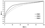
- Fig. 1 shows a charging curve of 5C charging measured with the batteries obtained in Examples 1 to 3. It can be seen that the cell can be charged from a low potential state by mixing the carbon material (B) having low crystallinity. This is considered to be due to the increase in Li ion acceptability at the initial stage of charging due to the carbon material (B), thereby enabling smooth charging.
Landscapes
- Chemical & Material Sciences (AREA)
- Engineering & Computer Science (AREA)
- Chemical Kinetics & Catalysis (AREA)
- Electrochemistry (AREA)
- General Chemical & Material Sciences (AREA)
- Materials Engineering (AREA)
- Manufacturing & Machinery (AREA)
- Inorganic Chemistry (AREA)
- Battery Electrode And Active Subsutance (AREA)
- Secondary Cells (AREA)
- Carbon And Carbon Compounds (AREA)
Abstract
粉末X線回折法によって測定される黒鉛構造の(002)面の面間隔(d(002))が0.335~0.339nmの範囲にあり、レーザー回折法により測定した粒度分布の体積累計頻度が50%である粒子径(D50)が4~10μmである人造黒鉛(A)、及びd(002)が0.340nm以上であり、D50が7~17μmであってかつD50が前記人造黒鉛(A)のD50よりも大きい炭素材料(B)の混合物を含むことを特徴とするリチウムイオン二次電池用負極材。
Description
本発明は、高い出力及び高エネルギー密度を維持したまま、高速充電特性に優れたリチウムイオン二次電池とすることのできる負極材に関する。また、本発明はその負極材を用いたリチウムイオン二次電池用負極シート、及びリチウム二次電池に関する。
リチウムイオン二次電池は携帯電子機器の電源として使用されているほか、近年では電動工具や電気自動車などの電源としても使用されている。バッテリー電気自動車(BEV)、ハイブリッド電気自動車(HEV)などの電気自動車においては、10年間以上に亘って高い充放電サイクル特性を維持すること、ハイパワーモーターを駆動させるために十分な大電流負荷特性を有すること、および航続距離を伸ばすために高い体積エネルギー密度を有することが要求される。特にプラグインハイブリッド自動車(PHEV)は、搭載される電池容量がEVと比べ小さく、低容量の電池でモーターを駆動しトリクル充電を行わなければならないため、大電流負荷特性が重視される。
従来、負極材としては黒鉛をはじめとする炭素系材料が主として用いられてきたが、最近では金属系負極材の開発も行われている。しかし、サイクル寿命や安定性等の問題があり、未だ課題が多く残されているのが現状である。
従来、負極材としては黒鉛をはじめとする炭素系材料が主として用いられてきたが、最近では金属系負極材の開発も行われている。しかし、サイクル寿命や安定性等の問題があり、未だ課題が多く残されているのが現状である。
炭素系材料には大きく分けて結晶化度の高い黒鉛材料、結晶化度の低いアモルファス炭素材料があるが、いずれもリチウムの挿入脱離反応が可能であることから、負極活物質に用いることができる。
黒鉛材料には、天然黒鉛と人造黒鉛がある。天然黒鉛は球状に造粒してなるものが知られている。例えば、特許文献1には、球状に造粒してなる天然黒鉛の表面に人造カーボンをコーティングしてなる黒鉛材料が記載されている。この黒鉛材料を用いてなるリチウムイオン二次電池は、携帯電子機器の電源として要求される性能をある程度有しているが、電気自動車や電動工具などの電源として要求される性能には十分に達していない。高結晶性黒鉛材料はサイクル特性が安定である代わりに、充電特性は十分ではない。急速充放電を行う際に、負極活物質側でのリチウムイオンの挿入脱離反応が間に合わず、電池の電圧が急激に下限値若しくは上限値まで達し、それ以上反応が進まなくなるためであり、これは高結晶性の黒鉛材料に顕著である。しかし、黒鉛の理論電池容量相等の容量を得ることができること、サイクル特性が安定していることなどから、現在は高結晶性の黒鉛材料が広く負極材として用いられている。
黒鉛材料には、天然黒鉛と人造黒鉛がある。天然黒鉛は球状に造粒してなるものが知られている。例えば、特許文献1には、球状に造粒してなる天然黒鉛の表面に人造カーボンをコーティングしてなる黒鉛材料が記載されている。この黒鉛材料を用いてなるリチウムイオン二次電池は、携帯電子機器の電源として要求される性能をある程度有しているが、電気自動車や電動工具などの電源として要求される性能には十分に達していない。高結晶性黒鉛材料はサイクル特性が安定である代わりに、充電特性は十分ではない。急速充放電を行う際に、負極活物質側でのリチウムイオンの挿入脱離反応が間に合わず、電池の電圧が急激に下限値若しくは上限値まで達し、それ以上反応が進まなくなるためであり、これは高結晶性の黒鉛材料に顕著である。しかし、黒鉛の理論電池容量相等の容量を得ることができること、サイクル特性が安定していることなどから、現在は高結晶性の黒鉛材料が広く負極材として用いられている。
アモルファス炭素材料は、黒鉛では充電不可能な低電位領域から充電できるため急速充放電でも使用できることが知られているが、サイクル劣化が著しく、不可逆容量が大きい上に容量が小さいという欠点を持つ。
上記背景から、アモルファス材料と高結晶性黒鉛材を複合化させるなど、両方の特徴を持ち合わせた材料の開発研究が盛んに行われ、様々な技術が提案されている。
特許文献2には、芯材となる炭素材料をタール又はピッチに浸漬させ、それを乾燥又は900~1300℃で熱処理する技術が開示されている。
特許文献3には、天然黒鉛又は鱗状人造黒鉛を造粒させた黒鉛粒子の表面にピッチなど炭素前駆体を混合し、不活性ガス雰囲気下で700~2800℃の温度範囲で焼成させる技術が開示されている。
特許文献4には、d(002)が0.3356nm、R値が0.07前後、Lcが約50nmである鱗片状黒鉛を機械的外力で造粒球状化した球状黒鉛粒子に、フェノール樹脂などの樹脂の加熱炭化物を被覆してなる複合黒鉛粒子を負極活物質として用いることが開示されている。この複合黒鉛粒子は、窒素雰囲気下1000℃で炭化のための前処理をし、3000℃で炭化処理することによって得られる。
特許文献5では、平均粒子径15μmで表面が低結晶性炭素である黒鉛系炭素材と、平均粒子径10μmの低結晶性炭素を混合した混合炭素材料を負極活物質として用いることが開示されている。
特許文献3には、天然黒鉛又は鱗状人造黒鉛を造粒させた黒鉛粒子の表面にピッチなど炭素前駆体を混合し、不活性ガス雰囲気下で700~2800℃の温度範囲で焼成させる技術が開示されている。
特許文献4には、d(002)が0.3356nm、R値が0.07前後、Lcが約50nmである鱗片状黒鉛を機械的外力で造粒球状化した球状黒鉛粒子に、フェノール樹脂などの樹脂の加熱炭化物を被覆してなる複合黒鉛粒子を負極活物質として用いることが開示されている。この複合黒鉛粒子は、窒素雰囲気下1000℃で炭化のための前処理をし、3000℃で炭化処理することによって得られる。
特許文献5では、平均粒子径15μmで表面が低結晶性炭素である黒鉛系炭素材と、平均粒子径10μmの低結晶性炭素を混合した混合炭素材料を負極活物質として用いることが開示されている。
特許文献1~4に記載の炭素材料では、充電特性がいずれも十分でなかった。また、サイクル特性が不十分であった。
特許文献5に記載の炭素材料は低温特性は良好であるが、放電特性は不十分である。
特許文献5に記載の炭素材料は低温特性は良好であるが、放電特性は不十分である。
本発明の好ましい実施態様におけるリチウムイオン二次電池用負極材、その負極材を用いたリチウムイオン二次電池用負極シート、及びリチウム二次電池は以下の通りである。
[1]粉末X線回折法によって測定される黒鉛構造の(002)面の面間隔(d(002))が0.335~0.339nmの範囲にあり、レーザー回折法により測定した粒度分布の体積累計頻度が50%である粒子径(D50)が4~10μmである人造黒鉛(A)、及び
d(002)が0.340nm以上であり、D50が7~17μmであってかつD50が前記人造黒鉛(A)のD50よりも大きい炭素材料(B)
の混合物を含むことを特徴とするリチウムイオン二次電池用負極材。
[2]前記人造黒鉛(A)と前記炭素材料(B)の組成比が、質量比で、8:2から2:8の範囲である前記1に記載のリチウムイオン二次電池用負極材。
[3]前記人造黒鉛(A)が、石油系及び/または石炭系コークスを2500℃以上で熱処理したものである前記1に記載のリチウムイオン二次電池用負極材。
[4]前記人造黒鉛(A)が、芯材としての人造黒鉛の粒子表面に炭素コーティング層を有する粒子からなる前記1に記載のリチウムイオン二次電池用負極材。
[5]前記の芯材としての人造黒鉛が、石油系及び/または石炭系コークスを2500℃以上で熱処理したものである前記4に記載のリチウムイオン二次電池用負極材。
[6]前記コーティング層の、ラマン分光スペクトルで測定される1300~1400cm-1の範囲にあるピーク強度(ID)と1580~1620cm-1の範囲にあるピーク強度(IG)との強度比ID/IG(R値)が0.1以上である前記4または5に記載のリチウムイオン二次電池用負極材。
[7]芯材としての前記人造黒鉛を100質量部としたとき、前記コーティング層の量が0.05~10質量部である前記4-6のいずれかに記載のリチウムイオン二次電池用負極材。
[8]前記人造黒鉛(A)が、芯材としての人造黒鉛の粒子に有機化合物を付着させた後、500℃以上2000℃以下の温度で熱処理して得られるものである前記4-7のいずれかに記載のリチウムイオン二次電池用負極材。
[9]前記有機化合物が、石油系ピッチ、石炭系ピッチ、フェノール樹脂、ポリビニルアルコール樹脂、フラン樹脂、セルロース樹脂、ポリスチレン樹脂、ポリイミド樹脂及びエポキシ樹脂からなる群から選択される少なくとも1種の化合物である前記8に記載のリチウムイオン二次電池用負極材。
[10]前記人造黒鉛(A)のBET比表面積が0.5~5m2/gである前記1に記載のリチウムイオン二次電池用負極材。
[11]前記炭素材料(B)が、ハードカーボン及び/またはソフトカーボンである前記1に記載のリチウムイオン二次電池用負極材。
[12]前記1-11のいずれかに記載のリチウムイオン二次電池用負極材とバインダーと分散媒とを含む負極用ペーストを集電箔上に塗布、乾燥し、加圧成形して得られるリチウムイオン二次電池用負極シート。
[13]集電箔以外の負極部分の密度が1.1g/cm3以上1.6g/cm3以下である前記12に記載のリチウムイオン二次電池用負極シート。
[14]前記12または13に記載のリチウムイオン二次電池用負極シートを構成要素として含むリチウムイオン電池。
[15]非水系電解液及び/または非水系ポリマー電解質を用い、前記非水系電解液及び/または非水系ポリマー電解質に用いられる非水系溶媒にプロピレンカーボネートが含まれている前記14に記載のリチウムイオン電池。
[1]粉末X線回折法によって測定される黒鉛構造の(002)面の面間隔(d(002))が0.335~0.339nmの範囲にあり、レーザー回折法により測定した粒度分布の体積累計頻度が50%である粒子径(D50)が4~10μmである人造黒鉛(A)、及び
d(002)が0.340nm以上であり、D50が7~17μmであってかつD50が前記人造黒鉛(A)のD50よりも大きい炭素材料(B)
の混合物を含むことを特徴とするリチウムイオン二次電池用負極材。
[2]前記人造黒鉛(A)と前記炭素材料(B)の組成比が、質量比で、8:2から2:8の範囲である前記1に記載のリチウムイオン二次電池用負極材。
[3]前記人造黒鉛(A)が、石油系及び/または石炭系コークスを2500℃以上で熱処理したものである前記1に記載のリチウムイオン二次電池用負極材。
[4]前記人造黒鉛(A)が、芯材としての人造黒鉛の粒子表面に炭素コーティング層を有する粒子からなる前記1に記載のリチウムイオン二次電池用負極材。
[5]前記の芯材としての人造黒鉛が、石油系及び/または石炭系コークスを2500℃以上で熱処理したものである前記4に記載のリチウムイオン二次電池用負極材。
[6]前記コーティング層の、ラマン分光スペクトルで測定される1300~1400cm-1の範囲にあるピーク強度(ID)と1580~1620cm-1の範囲にあるピーク強度(IG)との強度比ID/IG(R値)が0.1以上である前記4または5に記載のリチウムイオン二次電池用負極材。
[7]芯材としての前記人造黒鉛を100質量部としたとき、前記コーティング層の量が0.05~10質量部である前記4-6のいずれかに記載のリチウムイオン二次電池用負極材。
[8]前記人造黒鉛(A)が、芯材としての人造黒鉛の粒子に有機化合物を付着させた後、500℃以上2000℃以下の温度で熱処理して得られるものである前記4-7のいずれかに記載のリチウムイオン二次電池用負極材。
[9]前記有機化合物が、石油系ピッチ、石炭系ピッチ、フェノール樹脂、ポリビニルアルコール樹脂、フラン樹脂、セルロース樹脂、ポリスチレン樹脂、ポリイミド樹脂及びエポキシ樹脂からなる群から選択される少なくとも1種の化合物である前記8に記載のリチウムイオン二次電池用負極材。
[10]前記人造黒鉛(A)のBET比表面積が0.5~5m2/gである前記1に記載のリチウムイオン二次電池用負極材。
[11]前記炭素材料(B)が、ハードカーボン及び/またはソフトカーボンである前記1に記載のリチウムイオン二次電池用負極材。
[12]前記1-11のいずれかに記載のリチウムイオン二次電池用負極材とバインダーと分散媒とを含む負極用ペーストを集電箔上に塗布、乾燥し、加圧成形して得られるリチウムイオン二次電池用負極シート。
[13]集電箔以外の負極部分の密度が1.1g/cm3以上1.6g/cm3以下である前記12に記載のリチウムイオン二次電池用負極シート。
[14]前記12または13に記載のリチウムイオン二次電池用負極シートを構成要素として含むリチウムイオン電池。
[15]非水系電解液及び/または非水系ポリマー電解質を用い、前記非水系電解液及び/または非水系ポリマー電解質に用いられる非水系溶媒にプロピレンカーボネートが含まれている前記14に記載のリチウムイオン電池。
特定の人造黒鉛と特定の炭素材料との混合物を含む材料をリチウム二次電池用負極材として用いることにより、充放電特性及びサイクル特性、並びにその性能バランスに優れたリチウム二次電池とすることができる。また、前記人造黒鉛として、黒鉛粒子表面に炭素コーティング層を設けたものを用いることにより、より一層サイクル特性を向上させることが可能である。
<リチウムイオン二次電池用負極材>
本発明の好ましい実施態様におけるリチウムイオン二次電池用負極材は、人造黒鉛(A)と、前記人造黒鉛(A)よりも平均粒子径(D50,下記参照)が大きく、結晶度の低い炭素材料(B)との混合物を含む。
本発明の好ましい実施態様におけるリチウムイオン二次電池用負極材は、人造黒鉛(A)と、前記人造黒鉛(A)よりも平均粒子径(D50,下記参照)が大きく、結晶度の低い炭素材料(B)との混合物を含む。
[人造黒鉛(A)]
人造黒鉛(A)は、粉末X線回折法によって測定される黒鉛構造の(002)面の面間隔(d(002))が0.335~0.339nmの範囲にあることが好ましい。より好ましいd(002)は0.335~0.337nmの範囲である。d(002)が大きくなると、放電容量が小さく、真密度も低くなるため、エネルギー密度の低い電池になる。また、結晶性が低く導電性に劣るため、放電特性も低下する傾向がある。また、c軸方向の結晶子の厚さ(Lc)は50nm以上が好ましい。
人造黒鉛(A)は、粉末X線回折法によって測定される黒鉛構造の(002)面の面間隔(d(002))が0.335~0.339nmの範囲にあることが好ましい。より好ましいd(002)は0.335~0.337nmの範囲である。d(002)が大きくなると、放電容量が小さく、真密度も低くなるため、エネルギー密度の低い電池になる。また、結晶性が低く導電性に劣るため、放電特性も低下する傾向がある。また、c軸方向の結晶子の厚さ(Lc)は50nm以上が好ましい。
人造黒鉛(A)は、レーザー回折法により測定した粒度分布の体積累計頻度が50%である粒子径(D50)(本明細書において平均粒子径と称する場合がある)が4~10μmであることが好ましい。D50は、より好ましくは4~8μmであり、さらに好ましくは4~6μmである。D50が上記範囲にあることにより、リチウムイオンが効率よく電解液と反応し優れた放電特性を示した上で、容量及びサイクル特性を高く維持することができる。D50が小さすぎるとリチウムイオンと電気化学的な反応に効率よく関与できない粒子が増え、容量およびサイクル特性が低下する傾向がある。逆にD50が大きすぎると、電解液との接触面積が小さくなることから、出力特性が低下する傾向がある。
また、人造黒鉛(A)は、レーザー回折法による粒度分布測定における個数基準累計粒度分布において90%以上の個数の粒子が4~10μmの範囲にあることが望ましい。上記範囲にある黒鉛は効率良く電解液と反応するため、優れた充放電特性を示す。
また、人造黒鉛(A)は、レーザー回折法による粒度分布測定における個数基準累計粒度分布において90%以上の個数の粒子が4~10μmの範囲にあることが望ましい。上記範囲にある黒鉛は効率良く電解液と反応するため、優れた充放電特性を示す。
粒度分布は、粉砕及び分級によって調整することができる。粉砕装置としては、例えば、ハンマーミル、ジョークラッシャー、衝突式粉砕器などが挙げられる。また、分級は、気流分級法、篩分級法にて行うことができる。気流分級装置としては、例えば、ターボクラシファイヤー、ターボプレックスなどが挙げられる。
人造黒鉛(A)は、そのBET比表面積が、好ましくは0.5~5m2/g、より好ましくは0.5~3.5m2/gである。BET比表面積が上記範囲にあることにより、クーロン効率が良く、サイクル・出力特性のバランスの取れた黒鉛となる。BET比表面積が大きすぎると粒子の表面活性が高くなり、電解液の分解などによってクーロン効率が低下し、またサイクル特性が低下する傾向がある。また、BET比表面積が小さすぎると電解液との接触面積が少なくなり、出力特性が低下する傾向がある。
人造黒鉛(A)は、粒子表面に炭素コーティング層を有するものであってもよい。その場合の芯材としては、上記した人造黒鉛(A)と同様のものを用いることができる。芯材及びコーティング層からなる人造黒鉛(A)(以下、複合化黒鉛という場合がある)を用いることにより、入出力特性を向上させることができる。
前記複合化黒鉛のコーティング層は、ラマン分光スペクトルで測定される1300~1400cm-1の範囲にあるピーク強度(ID)と1580~1620cm-1の範囲にあるピーク強度(IG)との強度比ID/IG(R値)が0.1以上の炭素からなるものが好ましい。さらに好ましいR値は0.20以上である。R値の大きな表層を設けることにより、黒鉛層間へのリチウムイオンの挿入・脱離が容易になり、二次電池の電極材としたときの急速充電性が改善する。なお、R値は大きいほど結晶性が低いことを示す。
人造黒鉛(A)の製造に用いる炭素原料は、不活性雰囲気下で300℃から1200℃まで加熱した際の加熱減量分(例えば、炭化に伴う炭化水素の揮発分)が5~20質量%のものであることが好ましい。この加熱減量分が少ないと粉砕後に粒子形状が板状になる傾向があり、また、粉砕面(エッジ部分)が露出しており比表面積が大きくなり副反応が多くなる傾向がある。逆に当該加熱減量分が多いと黒鉛化の過程で粒子同士が多く結着し、収率に影響する傾向がある。
このような加熱減量分を有する炭素原料は、石油系ピッチコークス又は石炭系ピッチコークスから選択される。特に人造黒鉛(A)のための炭素原料は石油コークスの一種である生コークスにより選択されるものが好ましい。生コークスは結晶が未発達であるので粉砕したときに球状になり、比表面積は小さくなりやすい。従って炭素原料は非針状のコークスであることが好ましい。
石油コークスは、石油または歴青油のクラッキング又は分解蒸留により得られる黒色で多孔質の固形残留物である。石油コークスには、コーキングの方法によりフルード・コークスとディレード・コークスがある。しかし、フルード・コークスは粉状で、製油所の自家燃料に使用される程度であまり用途が無く、一般に石油コークスと称するのはディレード・コークスのことである。ディレード・コークスには、生コークスとか焼コークスとがある。生コークスはコーキング装置から採取されたそのままのコークスで、か焼コークスはこれをさらにもう一度焼いて揮発分を除去したものである。生コークスは粉じん爆発を起こす可能性が高いので、微粒子状の石油コークスを得るためには生コークスをか焼して揮発分を除去してから粉砕されていた。また、従来、電極などにはか焼コークスが一般に使われていた。生コークスは石炭コークスよりも灰分が少ないので、カーバイド工業の炭素材、鋳物用コークス、合金鉄用コークスなどに使用されるだけであった。
このような加熱減量分を有する炭素原料は、石油系ピッチコークス又は石炭系ピッチコークスから選択される。特に人造黒鉛(A)のための炭素原料は石油コークスの一種である生コークスにより選択されるものが好ましい。生コークスは結晶が未発達であるので粉砕したときに球状になり、比表面積は小さくなりやすい。従って炭素原料は非針状のコークスであることが好ましい。
石油コークスは、石油または歴青油のクラッキング又は分解蒸留により得られる黒色で多孔質の固形残留物である。石油コークスには、コーキングの方法によりフルード・コークスとディレード・コークスがある。しかし、フルード・コークスは粉状で、製油所の自家燃料に使用される程度であまり用途が無く、一般に石油コークスと称するのはディレード・コークスのことである。ディレード・コークスには、生コークスとか焼コークスとがある。生コークスはコーキング装置から採取されたそのままのコークスで、か焼コークスはこれをさらにもう一度焼いて揮発分を除去したものである。生コークスは粉じん爆発を起こす可能性が高いので、微粒子状の石油コークスを得るためには生コークスをか焼して揮発分を除去してから粉砕されていた。また、従来、電極などにはか焼コークスが一般に使われていた。生コークスは石炭コークスよりも灰分が少ないので、カーバイド工業の炭素材、鋳物用コークス、合金鉄用コークスなどに使用されるだけであった。
次にこの炭素原料を粉砕する。炭素原料の粉砕には公知のジェットミル、ハンマーミル、ローラーミル、ピンミル、振動ミルなどが用いられる。炭素原料の粉砕はできるだけ低い熱履歴を有する炭素原料で行うことが好ましい。低い熱履歴を有する炭素原料で粉砕を行うと、炭素原料の粉砕が容易である上、破砕時の亀裂方向がほぼランダムになり、アスペクト比が小さくなる傾向がある。また、後の加熱プロセスで粉砕面に露出したエッジ部分が修復される確率が高まり、充放電時の副反応を低減できる効果がある。
粉砕した炭素原料は、黒鉛化処理を施す前に、非酸化性雰囲気下で500~1200℃程度で低温焼成することができる。この低温焼成によって次に行う黒鉛化処理でのガス発生を低減させることができ、また、嵩密度を下げられることから黒鉛化処理コストを低減することができる。
粉砕された炭素原料の黒鉛化処理は、炭素原料が酸化しにくい雰囲気で行うことが望ましい。例えば、アルゴンガスなどの雰囲気で熱処理する方法、アチソン炉で熱処理する方法(非酸化黒鉛化プロセス)などが挙げられる。これらのうち非酸化黒鉛化プロセスがコストの観点から好ましい。
黒鉛化処理における温度の下限は、通常2000℃、好ましくは2500℃、さらに好ましくは2900℃、もっとも好ましくは3000℃である。黒鉛化処理における温度の上限は特に限定されないが、高い放電容量が得られやすいという観点から、好ましくは3300℃である。
黒鉛化処理における温度の下限は、通常2000℃、好ましくは2500℃、さらに好ましくは2900℃、もっとも好ましくは3000℃である。黒鉛化処理における温度の上限は特に限定されないが、高い放電容量が得られやすいという観点から、好ましくは3300℃である。
黒鉛化処理の後、得られた人造黒鉛を解砕または粉砕しないことが好ましい。黒鉛化処理後に解砕または粉砕すると、滑らかになった表面が傷つき、性能が低下するおそれがある。
得られた人造黒鉛は、そのまま負極材として使用することができる。また、前記人造黒鉛を芯材としてその表面を炭素材料によりコーティングをし、複合化して負極材として使用することもできる。
複合化は、公知の方法に従って行うことができ、例えば、得られた人造黒鉛に有機化合物を噴きかけながら撹拌する。また、奈良機械製ハイブリダイザー等の装置により前記人造黒鉛と前記有機化合物を混合し、その後、熱処理をかける段階で自然に前記黒鉛表面に付着させ複合化することもできる。
複合化は、公知の方法に従って行うことができ、例えば、得られた人造黒鉛に有機化合物を噴きかけながら撹拌する。また、奈良機械製ハイブリダイザー等の装置により前記人造黒鉛と前記有機化合物を混合し、その後、熱処理をかける段階で自然に前記黒鉛表面に付着させ複合化することもできる。
好ましいコーティング層は、有機化合物を200℃以上3000℃以下、好ましくは500℃以上2000℃以下で熱処理して得られたものである。最終の熱処理温度は、低すぎると炭素化が十分に終了せず水素や酸素が残留し電池特性に悪影響を及ぼす可能性があることから、500℃以上が望ましい。また、処理温度が高すぎると黒鉛結晶化が進みすぎて充電特性が低下する恐れがあることから、2000℃以下が望ましい。
前記有機化合物は特に限定されないが、等方性ピッチ、異方性ピッチ、樹脂又は樹脂前駆体若しくはモノマーが好ましい。樹脂前駆体若しくはモノマーを用いた場合は、樹脂前駆体若しくはモノマーを重合して樹脂にすることが好ましい。好適な有機化合物としては、石油系ピッチ、石炭系ピッチ、フェノール樹脂、ポリビニルアルコール樹脂、フラン樹脂、セルロース樹脂、ポリスチレン樹脂、ポリイミド樹脂及びエポキシ樹脂からなる群から選択される少なくとも1種の化合物が挙げられる。
有機化合物の使用量は人造黒鉛100質量部に対して0.1~10質量部が好ましい。
有機化合物の使用量は人造黒鉛100質量部に対して0.1~10質量部が好ましい。
熱処理は、非酸化性雰囲気で行うことが好ましい。非酸化性雰囲気としては、アルゴンガス、窒素ガスなどの不活性ガスを充満させた雰囲気が挙げられる。
前記熱処理の後、解砕することが好ましい。前記熱処理によって、人造黒鉛同士が融着して塊になるので、電極活物質として用いるために微粒化する。
コーティング層の厚みはnmオーダーであるので、複合化した人造黒鉛の粒子径は、芯材の粒子径とほぼ同等である。すなわち前記複合化黒鉛のD50は4~10μmが好ましく、4~8μmがより好ましく、4~6μmがさらに好ましい。
コーティング層の厚みはnmオーダーであるので、複合化した人造黒鉛の粒子径は、芯材の粒子径とほぼ同等である。すなわち前記複合化黒鉛のD50は4~10μmが好ましく、4~8μmがより好ましく、4~6μmがさらに好ましい。
複合化黒鉛は、複合化していない人造黒鉛(A)と同様に、全体の90%以上の個数の粒子が4~10μmの範囲にあることが望ましい。
また、複合化黒鉛のd(002)やBET比表面積についても、複合化していない人造黒鉛(A)と同じ範囲が好ましい。
また、複合化黒鉛のd(002)やBET比表面積についても、複合化していない人造黒鉛(A)と同じ範囲が好ましい。
コーティング層を有する場合、芯材としての人造黒鉛とコーティング層との割合は、特に限定されないが、芯材を100質量部としたとき、コーティング層が0.05~10質量部が好ましく、0.1~10質量部がさらに好ましい。コーティング層の量が少なすぎると、コーティング層を形成したことに基づく効果が得られない。コーティング層の量が多すぎると電池容量が低下するおそれがある。コーティング層の量は、有機化合物を使用する場合はその量から算出できる。
[炭素材料(B)]
炭素材料(B)は、d(002)が0.340nm以上であることが好ましい。さらに好ましいd(002)は0.342nm以上である。d(002)が0.340nmより狭くなると、リチウムイオンの受け入れ性が下がり、充電効率が小さくなる。また、Lcは10nm以下が好ましい。
炭素材料(B)は、d(002)が0.340nm以上であることが好ましい。さらに好ましいd(002)は0.342nm以上である。d(002)が0.340nmより狭くなると、リチウムイオンの受け入れ性が下がり、充電効率が小さくなる。また、Lcは10nm以下が好ましい。
炭素材料(B)は、D50が7~17μmであることが好ましい。D50が上記範囲にあることにより、リチウムイオンが効率よく電解液と反応し優れた放電特性を示した上で、容量、サイクル特性を高く維持することができる。D50が小さすぎると比表面積が大きくなるため電解液との反応活性点が増加し、初回効率の低下に繋がる。D50が大きすぎると、電解液との接触面積が小さくなり、抵抗値、入出力特性が小さくなる。
また、炭素材料(B)のD50は、前記人造黒鉛(A)のD50よりも大きいことが好ましい。
また、炭素材料(B)のD50は、前記人造黒鉛(A)のD50よりも大きいことが好ましい。
炭素材料(B)は、BET比表面積の上限値が好ましくは7m2/g、より好ましくは6m2/gである。BET比表面積の下限値は、好ましくは0.5m2/g、より好ましくは1.0m2/gである。BET比表面積が大きすぎると電解液との接触面積が増大することから不可逆容量が大きく、またサイクル特性が低下する傾向がある。また比表面積が大きい炭素材料(B)を含む合剤(スラリー)は、粘度が高く、塗布性が低下する傾向がある。逆にBET比表面積が小さすぎると、電解液と反応面積が小さくなってしまうため、充放電特性が小さくなる傾向がある。
炭素材料(B)は易黒鉛化炭素(ソフトカーボン)及び難黒鉛化炭素(ハードカーボン)のいずれもが使用できる。
炭素材料(B)の原料は石炭系もしくは石油系の生コークス、か焼コークス、樹脂、樹脂前駆体、またはモノマーが用いられる。樹脂前駆体およびモノマーを使用する場合は、重合して樹脂にする方が好ましい。好適な樹脂としては、フェノール樹脂、ポリビニルアルコール樹脂、フラン樹脂、セルロース樹脂、ポリスチレン樹脂、ポリイミド樹脂、及びエポキシ樹脂等が挙げられ、これらは単独で、または組み合わせて用いることができる。
炭素材料(B)の原料は石炭系もしくは石油系の生コークス、か焼コークス、樹脂、樹脂前駆体、またはモノマーが用いられる。樹脂前駆体およびモノマーを使用する場合は、重合して樹脂にする方が好ましい。好適な樹脂としては、フェノール樹脂、ポリビニルアルコール樹脂、フラン樹脂、セルロース樹脂、ポリスチレン樹脂、ポリイミド樹脂、及びエポキシ樹脂等が挙げられ、これらは単独で、または組み合わせて用いることができる。
これらの原料はあらかじめオートクレーブ等で熱処理され粉砕されることが好ましい。粉砕には公知のジェットミル、ハンマーミル、ローラーミル、ピンミル、振動ミルなどが用いられる。
粉砕された材料は、非酸化性雰囲気下で700~1500℃程度で焼成する。材料の種類により好適な熱処理温度は異なるが、最終熱処理温度が低すぎると炭素化が十分に進行せず、水素、酸素等が残留し電池性能に悪影響を及ぼす可能性があるので700℃以上が好ましい。また、易黒鉛化炭素の場合は熱処理温度が高すぎると黒鉛結晶化が進行しすぎて充電特性が低下するおそれがあるため、1200℃以下の熱処理が好ましい。
ここで、易黒鉛化炭素(ソフトカーボン)とは、易黒鉛化性の有機物を700℃以上2000℃以下で熱処理した炭素材料をいう。また、難黒鉛化炭素(ハードカーボン)とは、難黒鉛化性有機物を熱処理した炭素材料をいう。
[混合]
本発明の好ましい実施態様におけるリチウムイオン二次電池用負極材は、前記人造黒鉛(A)と前記炭素材料(B)とを混合することにより製造することができる。
混合方法は、特に限定されない。例えば、ヘンシェルミキサーやスパルタンリューザーのような高速チョッパーを有するものや、ナウターミキサー、リボンミキサーなどを用いて、高速に均一に混合することができる。
前記人造黒鉛(A)と前記炭素材料(B)との混合比率は、要求特性に応じて異なる。例えば、エネルギー密度が重要視されるBEVでは、前記人造黒鉛(A)が30~80質量%、前記炭素材料(B)が70~20質量%が好ましく、前記人造黒鉛(A)が50~80質量%、前記炭素材料(B)が50~20質量%がさらに好ましい。入力特性が重要視されるPHEVでは、前記人造黒鉛(A)が20~60質量%、前記炭素材料(B)が80~40質量%が好ましく、前記人造黒鉛(A)が20~40質量%、前記炭素材料(B)が80~60質量%がさらに好ましい。人造黒鉛(A)の割合が20質量%より少ないと、電極密度、電池容量、出力密度が低下し、さらにサイクル特性が低下する傾向がある。炭素材料(B)の割合が20質量%より少ないと、電極のリチウムイオン受け入れ性が低下し、十分な充電特性の改善効果が得られなくなる。
本発明の好ましい実施態様におけるリチウムイオン二次電池用負極材は、前記人造黒鉛(A)と前記炭素材料(B)とを混合することにより製造することができる。
混合方法は、特に限定されない。例えば、ヘンシェルミキサーやスパルタンリューザーのような高速チョッパーを有するものや、ナウターミキサー、リボンミキサーなどを用いて、高速に均一に混合することができる。
前記人造黒鉛(A)と前記炭素材料(B)との混合比率は、要求特性に応じて異なる。例えば、エネルギー密度が重要視されるBEVでは、前記人造黒鉛(A)が30~80質量%、前記炭素材料(B)が70~20質量%が好ましく、前記人造黒鉛(A)が50~80質量%、前記炭素材料(B)が50~20質量%がさらに好ましい。入力特性が重要視されるPHEVでは、前記人造黒鉛(A)が20~60質量%、前記炭素材料(B)が80~40質量%が好ましく、前記人造黒鉛(A)が20~40質量%、前記炭素材料(B)が80~60質量%がさらに好ましい。人造黒鉛(A)の割合が20質量%より少ないと、電極密度、電池容量、出力密度が低下し、さらにサイクル特性が低下する傾向がある。炭素材料(B)の割合が20質量%より少ないと、電極のリチウムイオン受け入れ性が低下し、十分な充電特性の改善効果が得られなくなる。
<リチウムイオン二次電池>
[負極用ペースト]
本発明の好ましい実施態様における負極用ペーストは、前記負極材とバインダーと分散媒とを含む。この負極用ペーストは、導電助剤を含んでも良い。
この負極用ペーストは、前記負極材とバインダーと分散媒とを混練することによって得ることができる。負極用ペーストは、シート状、ペレット状等の形状に成形することができる。
バインダーとしては、例えば、ポリエチレン、ポリプロピレン、エチレンプロピレンターポリマー、ブタジエンゴム、スチレンブタジエンゴム、ブチルゴム、イオン伝導率の大きな高分子化合物等が挙げられる。イオン伝導率の大きな高分子化合物としては、ポリフッ化ビニリデン、ポリエチレンオキサイド、ポリエピクロルヒドリン、ポリファスファゼン、ポリアクリロニトリル等が挙げられる。複合黒鉛とバインダーとの混合比率は、複合黒鉛100質量部に対して、バインダーを0.5~20質量部用いることが好ましい。
[負極用ペースト]
本発明の好ましい実施態様における負極用ペーストは、前記負極材とバインダーと分散媒とを含む。この負極用ペーストは、導電助剤を含んでも良い。
この負極用ペーストは、前記負極材とバインダーと分散媒とを混練することによって得ることができる。負極用ペーストは、シート状、ペレット状等の形状に成形することができる。
バインダーとしては、例えば、ポリエチレン、ポリプロピレン、エチレンプロピレンターポリマー、ブタジエンゴム、スチレンブタジエンゴム、ブチルゴム、イオン伝導率の大きな高分子化合物等が挙げられる。イオン伝導率の大きな高分子化合物としては、ポリフッ化ビニリデン、ポリエチレンオキサイド、ポリエピクロルヒドリン、ポリファスファゼン、ポリアクリロニトリル等が挙げられる。複合黒鉛とバインダーとの混合比率は、複合黒鉛100質量部に対して、バインダーを0.5~20質量部用いることが好ましい。
分散媒は、特に制限はなく、N-メチル-2-ピロリドン、ジメチルホルムアミド、イソプロパノール、水等が挙げられる。分散媒として水を使用するバインダーの場合は、増粘剤を併用することが好ましい。分散媒の量は集電体に塗布しやすいような粘度となるように調整される。
導電助剤としては、特に制限はなく、アセチレンブラック、ケッチェンブラック、炭素繊維等が挙げられる。特に、結晶性が高く、熱伝導性の高い気相法炭素繊維が好ましい。その配合量は負極材(負極活物質)100質量部としたとき0.01~20質量部程度が好ましい。導電助剤を添加することにより、電極への導電性の付与がされ電池寿命も良くなる。
導電助剤としては、特に制限はなく、アセチレンブラック、ケッチェンブラック、炭素繊維等が挙げられる。特に、結晶性が高く、熱伝導性の高い気相法炭素繊維が好ましい。その配合量は負極材(負極活物質)100質量部としたとき0.01~20質量部程度が好ましい。導電助剤を添加することにより、電極への導電性の付与がされ電池寿命も良くなる。
[負極]
前記負極用ペーストを集電体上に塗布し、乾燥し、加圧成形することにより、負極を得ることができる。
集電体としては、例えばニッケル、銅等の箔、メッシュなどが挙げられる。ペーストの塗布方法は特に制限されない。ペーストの塗布厚は、通常50~200μmである。塗布厚が大きくなりすぎると、規格化された電池容器に負極を収容できなくなることや、リチウムイオン拡散距離の増大による電池の内部抵抗の増加に繋がる。
加圧成形法としては、ロール加圧、プレス加圧等の成形法を挙げることができる。加圧成形するときの圧力は約100MPa~約300MPa(1~3t/cm2程度)が好ましい。このようにして得られた負極は、リチウム二次電池に好適である。
加圧成形後の電極密度は、1.1~1.6g/cm3が望ましい。電極密度が1.1g/cm3より小さいと体積エネルギー密度が小さい電池となり、逆に1.6g/cm3よりも大きいと電極内の空隙が少なくなり、電解液の浸透が悪くなる、リチウムイオンの拡散が悪くなり充放電特性が小さくなるという問題がある。
前記負極用ペーストを集電体上に塗布し、乾燥し、加圧成形することにより、負極を得ることができる。
集電体としては、例えばニッケル、銅等の箔、メッシュなどが挙げられる。ペーストの塗布方法は特に制限されない。ペーストの塗布厚は、通常50~200μmである。塗布厚が大きくなりすぎると、規格化された電池容器に負極を収容できなくなることや、リチウムイオン拡散距離の増大による電池の内部抵抗の増加に繋がる。
加圧成形法としては、ロール加圧、プレス加圧等の成形法を挙げることができる。加圧成形するときの圧力は約100MPa~約300MPa(1~3t/cm2程度)が好ましい。このようにして得られた負極は、リチウム二次電池に好適である。
加圧成形後の電極密度は、1.1~1.6g/cm3が望ましい。電極密度が1.1g/cm3より小さいと体積エネルギー密度が小さい電池となり、逆に1.6g/cm3よりも大きいと電極内の空隙が少なくなり、電解液の浸透が悪くなる、リチウムイオンの拡散が悪くなり充放電特性が小さくなるという問題がある。
[リチウム二次電池]
前記の負極を構成要素として、リチウム二次電池を製造することができる。
前記の負極を構成要素として、リチウム二次電池を製造することができる。
[正極]
リチウム二次電池の正極には、正極活物質として、通常、リチウム含有遷移金属酸化物が用いられ、好ましくはTi、V、Cr、Mn、Fe、Co、Ni、Mo及びWから選ばれる少なくとも1種の遷移金属元素とリチウムとを主として含有する酸化物であって、リチウムと遷移金属元素のモル比が0.3~2.2の化合物が用いられ、より好ましくはV、Cr、Mn、Fe、Co及びNiから選ばれる少なくとも1種の遷移金属元素とリチウムとを主として含有する酸化物であって、リチウムと遷移金属のモル比が0.3~2.2の化合物が用いられる。なお、主として存在する遷移金属に対し30モルパーセント未満の範囲でAl、Ga、In、Ge、Sn、Pb、Sb、Bi、Si、P、Bなどを含有していても良い。上記の正極活物質の中で、一般式LixMO2(MはCo、Ni、Fe、Mnの少なくとも1種、x=0~1.2。)、またはLiyN2O4(Nは少なくともMnを含む。y=0~2。)で表されるスピネル構造を有する材料の少なくとも1種を用いることが好ましい。
リチウム二次電池の正極には、正極活物質として、通常、リチウム含有遷移金属酸化物が用いられ、好ましくはTi、V、Cr、Mn、Fe、Co、Ni、Mo及びWから選ばれる少なくとも1種の遷移金属元素とリチウムとを主として含有する酸化物であって、リチウムと遷移金属元素のモル比が0.3~2.2の化合物が用いられ、より好ましくはV、Cr、Mn、Fe、Co及びNiから選ばれる少なくとも1種の遷移金属元素とリチウムとを主として含有する酸化物であって、リチウムと遷移金属のモル比が0.3~2.2の化合物が用いられる。なお、主として存在する遷移金属に対し30モルパーセント未満の範囲でAl、Ga、In、Ge、Sn、Pb、Sb、Bi、Si、P、Bなどを含有していても良い。上記の正極活物質の中で、一般式LixMO2(MはCo、Ni、Fe、Mnの少なくとも1種、x=0~1.2。)、またはLiyN2O4(Nは少なくともMnを含む。y=0~2。)で表されるスピネル構造を有する材料の少なくとも1種を用いることが好ましい。
さらに、正極活物質はLiyMaD1-aO2(MはCo、Ni、Fe、Mnの少なくとも1種、DはCo、Ni、Fe、Mn、Al、Zn、Cu、Mo、Ag、W、Ga、In、Sn、Pb、Sb、Sr、B、Pの中のM以外の少なくとも1種、y=0~1.2、a=0.5~1。)を含む材料、またはLiz(NbE1-b)2O4(NはMn、EはCo、Ni、Fe、Mn、Al、Zn、Cu、Mo、Ag、W、Ga、In、Sn、Pb、Sb、Sr、B、Pの少なくとも1種、b=1~0.2、z=0~2。)で表されるスピネル構造を有する材料の少なくとも1種を用いることが特に好ましい。
具体的には、LixCoO2、LixNiO2、LixMnO2、LixCoaNi1-aO2、LixCobV1-bOz、LixCobFe1-bO2、LixMn2O4、LixMncCo2-cO4、LixMncNi2-cO4、LixMncV2-cO4、LixMncFe2-cO4(ここでx=0.02~1.2、a=0.1~0.9、b=0.8~0.98、c=1.6~1.96、z=2.01~2.3。)が挙げられる。最も好ましいリチウム含有遷移金属酸化物としては、LixCoO2、LixNiO2、LixMnO2、LixCoaNi1-aO2、LixMn2O4、LixCobV1-bOz(x=0.02~1.2、a=0.1~0.9、b=0.9~0.98、z=2.01~2.3。)が挙げられる。なお、xの値は充放電開始前の値であり、充放電により増減する。
正極活物質の平均粒子サイズは特に限定されないが、0.1~50μmが好ましい。0.5~30μmの粒子の体積が95%以上であることが好ましい。粒径3μm以下の粒子群の占める体積が全体積の18%以下であり、かつ15μm以上25μm以下の粒子群の占める体積が、全体積の18%以下であることが更に好ましい。ここでの粒子径は、レーザー回折法による粒度分布測定における体積基準累計粒度分布により算出したものであり、平均粒子径は累計50%における粒子径である。
比表面積は特に限定されないが、BET法で0.01~50m2/gが好ましく、特に0.2m2/g~10m2/gが好ましい。また正極活物質5gを蒸留水100mlに溶かした時の上澄み液のpHとしては7以上12以下が好ましい。
比表面積は特に限定されないが、BET法で0.01~50m2/gが好ましく、特に0.2m2/g~10m2/gが好ましい。また正極活物質5gを蒸留水100mlに溶かした時の上澄み液のpHとしては7以上12以下が好ましい。
リチウム二次電池に用いられる電解液は、特に制限されない。例えば、LiClO4、LiPF6、LiAsF6、LiBF4、LiSO3CF3、CH3SO3Li、CF3SO3Li等のリチウム塩を、例えばエチレンカーボネート、ジエチルカーボネート、ジメチルカーボネート、メチルエチルカーボネート、ジエチルカーボネート、プロピレンカーボネート、ブチレンカーボネート、アセトニトリル、プロピロニトリル、ジメトキシエタン、テトラヒドロフラン、γ-ブチロラクトン等の非水系溶媒に溶かしたいわゆる有機電解液や、固体若しくはゲル状のいわゆるポリマー電解質を挙げることができる。
また、電解液には、リチウム二次電池の初回充電時に分解反応を示す添加剤を少量添加することが好ましい。添加剤としては例えば、ビニレンカーボネート、ビフェニール、プロパンスルトン等が挙げられる。添加量としては0.01~5質量%が好ましい。
本発明のリチウム二次電池には正極と負極との間にセパレーターを設けることができる。セパレーターとしては、例えば、ポリエチレン、ポリプロピレン等のポリオレフィンを主成分とした不織布、クロス、微孔フィルムまたはそれらを組み合わせたものなどを挙げることができる。
以下に本発明の実施例を示し、本発明をより具体的に説明する。なお、これらは説明のための単なる例示であって、本発明はこれらによって何ら制限されるものではない。なお、物性の測定方法、材料の調製方法及び電池の評価方法は以下に従った。
<物性の測定>
(1)比表面積
比表面積測定器(ユアサイオニクス社製NOVA1200)を用いて、液体窒素温度化(77K)における窒素ガス吸着量を求め、BET法により測定した。
(1)比表面積
比表面積測定器(ユアサイオニクス社製NOVA1200)を用いて、液体窒素温度化(77K)における窒素ガス吸着量を求め、BET法により測定した。
(2)粒子径
黒鉛を極小型スパーテル2杯分、及び非イオン性界面活性剤(TRITON(登録商標)-X)2滴を水50mlに添加し、3分間超音波分散させた。この分散液をCILAS社製レーザー回折式粒度分布測定器に投入し、粒度分布を測定し、体積基準で全粒子の90%以上の粒子が含まれる粒子径範囲を算出した。
この分布より算出した体積基準で50%となる粒径を平均粒子径(D50)とした。
黒鉛を極小型スパーテル2杯分、及び非イオン性界面活性剤(TRITON(登録商標)-X)2滴を水50mlに添加し、3分間超音波分散させた。この分散液をCILAS社製レーザー回折式粒度分布測定器に投入し、粒度分布を測定し、体積基準で全粒子の90%以上の粒子が含まれる粒子径範囲を算出した。
この分布より算出した体積基準で50%となる粒径を平均粒子径(D50)とした。
(3)d(002)及びLc
学振法に従って粉末X線回折法により、d(002)及びLcを求めた。
学振法に従って粉末X線回折法により、d(002)及びLcを求めた。
<材料の調製>
(1)人造黒鉛(A)
石油系コークスを原料に用い、平均粒子径(D50)が5μmとなるように粉砕を行った。これをアチソン炉にて3000℃の熱処理を行い、d(002)が0.336nm、Lc値が63nmの芯材を得た。これに粉末状の等方性ピッチを芯材に対して1質量%を混合し、アルゴン雰囲気下で1100℃にて熱処理を行って人造黒鉛(A)を得た。人造黒鉛(A)のBET比表面積は2.5m2/gであり、D50は5μmであった。
(2)炭素材料(B)
石油系コークスを原料に用い、平均粒子径(D50)15μmとなるように粉砕を行った。これを1100℃の熱処理を行い、d(002)が0.343nm、Lcが4.5nmの炭素材料(B)を得た。炭素材料(B)のBET比表面積は2.6m2/gであり、D50は15μmであった。
(1)人造黒鉛(A)
石油系コークスを原料に用い、平均粒子径(D50)が5μmとなるように粉砕を行った。これをアチソン炉にて3000℃の熱処理を行い、d(002)が0.336nm、Lc値が63nmの芯材を得た。これに粉末状の等方性ピッチを芯材に対して1質量%を混合し、アルゴン雰囲気下で1100℃にて熱処理を行って人造黒鉛(A)を得た。人造黒鉛(A)のBET比表面積は2.5m2/gであり、D50は5μmであった。
(2)炭素材料(B)
石油系コークスを原料に用い、平均粒子径(D50)15μmとなるように粉砕を行った。これを1100℃の熱処理を行い、d(002)が0.343nm、Lcが4.5nmの炭素材料(B)を得た。炭素材料(B)のBET比表面積は2.6m2/gであり、D50は15μmであった。
<電池の評価>
(1)負極作製
負極材100gに増粘剤としてカルボキシメチルセルロース(CMC)1.5g、水を適宜加えて粘度を調節し、固形分比40%のスチレン-ブタジエン(SBR)微粒子を含む水分散液3.8gを加え攪拌・混合し、充分な流動性を有するスラリー状の分散液を作製した。作製した分散液を厚み20μmの銅箔上にドクターブレードを用いて厚さ150μmで均一となるように塗布し、ホットプレートにて乾燥後、真空乾燥機で70℃、12時間乾燥した。乾燥した電極はロールプレスにより密度を調製し、電池評価用負極を得た。得られた電極の塗布量は7mg/cm2であり、電極密度は1.4g/cm3であった。
(2)正極作製
LiFePO4 90gと導電助剤としてカーボンブラック(TIMCAL社製)5g、および結着材としてポリフッ化ビニリデン(PVdF)5gにN-メチル-ピロリドンを適宜加えながら攪拌・混合し、スラリー状の分散液を作製した。
作製した分散液を厚さ20μmのアルミ箔上にロールコーターにより塗布し、乾燥させ、その後、ロールプレスにて加圧成形した。得られた正極の塗布量は10mg/cm2であり、電極密度は2.0g/cm3であった。
(1)負極作製
負極材100gに増粘剤としてカルボキシメチルセルロース(CMC)1.5g、水を適宜加えて粘度を調節し、固形分比40%のスチレン-ブタジエン(SBR)微粒子を含む水分散液3.8gを加え攪拌・混合し、充分な流動性を有するスラリー状の分散液を作製した。作製した分散液を厚み20μmの銅箔上にドクターブレードを用いて厚さ150μmで均一となるように塗布し、ホットプレートにて乾燥後、真空乾燥機で70℃、12時間乾燥した。乾燥した電極はロールプレスにより密度を調製し、電池評価用負極を得た。得られた電極の塗布量は7mg/cm2であり、電極密度は1.4g/cm3であった。
(2)正極作製
LiFePO4 90gと導電助剤としてカーボンブラック(TIMCAL社製)5g、および結着材としてポリフッ化ビニリデン(PVdF)5gにN-メチル-ピロリドンを適宜加えながら攪拌・混合し、スラリー状の分散液を作製した。
作製した分散液を厚さ20μmのアルミ箔上にロールコーターにより塗布し、乾燥させ、その後、ロールプレスにて加圧成形した。得られた正極の塗布量は10mg/cm2であり、電極密度は2.0g/cm3であった。
(3)電解液調製
非水溶媒として、エチレンカーボネート(EC)とエチルメチルカーボネート(EMC)を体積比3:7で混合し、電解質塩として六フッ化リン酸リチウム(LiPF6)を1.0mol/L溶解させたものを電解液とした。
非水溶媒として、エチレンカーボネート(EC)とエチルメチルカーボネート(EMC)を体積比3:7で混合し、電解質塩として六フッ化リン酸リチウム(LiPF6)を1.0mol/L溶解させたものを電解液とした。
(4)電池作製
上記負極および正極を打ち抜いて面積20cm2の負極片および正極片を得た。正極片のAl箔にAlタブを、負極片のCu箔にNiタブをそれぞれ取り付けた。ポリプロピレン製フィルム微多孔膜を負極片と正極片との間に挟み入れ、その状態でアルミラミネートにパックした。そして、それに電解液を注液した。その後、開口部を熱融着によって封止して評価用の電池(設計容量25mAh)を作製した。
上記負極および正極を打ち抜いて面積20cm2の負極片および正極片を得た。正極片のAl箔にAlタブを、負極片のCu箔にNiタブをそれぞれ取り付けた。ポリプロピレン製フィルム微多孔膜を負極片と正極片との間に挟み入れ、その状態でアルミラミネートにパックした。そして、それに電解液を注液した。その後、開口部を熱融着によって封止して評価用の電池(設計容量25mAh)を作製した。
(5)初回放電容量
上限電圧3.6VとしてCC(コンスタントカレント)、CV(コンスタントボルテージ)モードで、5mAで、カットオフ電流値1.25mAで充電を行った。
下限電圧2.5Vとして、CCモードで5mAの放電を行って、初回放電容量を測定した。
上限電圧3.6VとしてCC(コンスタントカレント)、CV(コンスタントボルテージ)モードで、5mAで、カットオフ電流値1.25mAで充電を行った。
下限電圧2.5Vとして、CCモードで5mAの放電を行って、初回放電容量を測定した。
(6)充放電レート試験
セルを上限電圧3.6V、カットオフ電流値1.25mAとしてCC、CVモードにより5mAで充電後、下限電圧2.5VでCCモードにより5C(約125mA)放電し、5Cにおけるエネルギー密度(mWh)を算出した。
また、セルを下限電圧2.5VとしてCCモードにより5mAで放電後、上限電圧3.6VとしてCCモードにより5Cで充電し、0.2C充電容量(0.2C=約5mA)を基準として、5Cにおける充電容量の比を算出した。
(5C充電容量(%))
=(5C充電容量(mAh))/(0.2C充電容量(mAh))×100
セルを上限電圧3.6V、カットオフ電流値1.25mAとしてCC、CVモードにより5mAで充電後、下限電圧2.5VでCCモードにより5C(約125mA)放電し、5Cにおけるエネルギー密度(mWh)を算出した。
また、セルを下限電圧2.5VとしてCCモードにより5mAで放電後、上限電圧3.6VとしてCCモードにより5Cで充電し、0.2C充電容量(0.2C=約5mA)を基準として、5Cにおける充電容量の比を算出した。
(5C充電容量(%))
=(5C充電容量(mAh))/(0.2C充電容量(mAh))×100
(7)サイクル特性の測定
上限電圧3.6VとしてCC、CVモードで、2C(2C=約50mA)で、カットオフ電流値1.25mAで充電を行った。
下限電圧2.5Vとして、CCモードで2C放電を行った。
上記条件で、500サイクル充放電を繰り返した。
500サイクル時の放電容量を測定した。初回放電容量に対する500サイクル時放電容量の割合を算出し、それを放電容量維持率とした。
(500サイクル後放電容量維持率(%))
=(500サイクル時放電容量)/(初回放電容量)×100
上限電圧3.6VとしてCC、CVモードで、2C(2C=約50mA)で、カットオフ電流値1.25mAで充電を行った。
下限電圧2.5Vとして、CCモードで2C放電を行った。
上記条件で、500サイクル充放電を繰り返した。
500サイクル時の放電容量を測定した。初回放電容量に対する500サイクル時放電容量の割合を算出し、それを放電容量維持率とした。
(500サイクル後放電容量維持率(%))
=(500サイクル時放電容量)/(初回放電容量)×100
実施例1
人造黒鉛(A)70質量部と、炭素材料(B)30質量部とを不二パンダル製スパルタンリューザーに入れ、5分間混合して、負極材を得た。得られた負極材はD50が8.2μm、BET比表面積が2.6m2/gであった。この負極材を用いて電極及び電池セルを作製し、電池特性の評価を行った。結果を表1に示す。
人造黒鉛(A)70質量部と、炭素材料(B)30質量部とを不二パンダル製スパルタンリューザーに入れ、5分間混合して、負極材を得た。得られた負極材はD50が8.2μm、BET比表面積が2.6m2/gであった。この負極材を用いて電極及び電池セルを作製し、電池特性の評価を行った。結果を表1に示す。
実施例2
人造黒鉛(A)の量を50質量部に、炭素材料(B)の量を50質量部に変えた以外は実施例1と同じ方法で負極材、電極及び電池セルを作製した。得られた負極材は、D50が9.9μm、BET比表面積が2.6m2/gであり、電池特性は表1に示すとおりであった。
人造黒鉛(A)の量を50質量部に、炭素材料(B)の量を50質量部に変えた以外は実施例1と同じ方法で負極材、電極及び電池セルを作製した。得られた負極材は、D50が9.9μm、BET比表面積が2.6m2/gであり、電池特性は表1に示すとおりであった。
実施例3
人造黒鉛(A)の量を30質量部に、炭素材料(B)の量を70質量部に変えた以外は実施例1と同じ方法で負極材、電極及び電池セルを作製した。得られた負極材は、D50が11.4μm、BET比表面積が2.5m2/gであり、電池特性は表1に示すとおりであった。
人造黒鉛(A)の量を30質量部に、炭素材料(B)の量を70質量部に変えた以外は実施例1と同じ方法で負極材、電極及び電池セルを作製した。得られた負極材は、D50が11.4μm、BET比表面積が2.5m2/gであり、電池特性は表1に示すとおりであった。
比較例1
平均粒子径(D50)が16μmとなるように粉砕を行なった以外は、前記人造黒鉛(A)の製法と同様に操作を行ない、BET比表面積が1.1m2/gであり、d(002)が0.336nmである人造黒鉛を得た。
得られた人造黒鉛50質量部と、炭素材料(B)50質量部とを不二パンダル製スパルタンリューザーに入れ、5分間混合して、負極材を得た。得られた負極材はD50が14.5μm、BET比表面積が1.8m2/gであった。この負極材を用いて電極及び電池セルを作製し、電池特性の評価を行った。結果を表1に示す。
平均粒子径(D50)が16μmとなるように粉砕を行なった以外は、前記人造黒鉛(A)の製法と同様に操作を行ない、BET比表面積が1.1m2/gであり、d(002)が0.336nmである人造黒鉛を得た。
得られた人造黒鉛50質量部と、炭素材料(B)50質量部とを不二パンダル製スパルタンリューザーに入れ、5分間混合して、負極材を得た。得られた負極材はD50が14.5μm、BET比表面積が1.8m2/gであった。この負極材を用いて電極及び電池セルを作製し、電池特性の評価を行った。結果を表1に示す。
比較例2
負極活物質として炭素材料(B)のみを用い、電極の潰れ性が劣るため負極の電極密度を1.3g/cm2とした以外は実施例1と同じ方法で電池特性の評価を行った。結果を表1に示す。
負極活物質として炭素材料(B)のみを用い、電極の潰れ性が劣るため負極の電極密度を1.3g/cm2とした以外は実施例1と同じ方法で電池特性の評価を行った。結果を表1に示す。

表1に示すとおり、実施例の負極材を用いることにより、放電時のエネルギー密度が高く、充電特性も高く、サイクル特性にも優れたバランスの良い性能を有するリチウムイオン二次電池とできることがわかる。
実施例1~3で得られた電池で測定した5C充電の充電曲線を図1に示す。結晶性の低い炭素材料(B)を混合することにより、セルが低電位の状態から充電できることがわかる。これは炭素材料(B)により充電初期のLiイオン受け入れ性が増加したものによると考えられ、これにより円滑な充電が可能となる。
Claims (15)
- 粉末X線回折法によって測定される黒鉛構造の(002)面の面間隔(d(002))が0.335~0.339nmの範囲にあり、レーザー回折法により測定した粒度分布の体積累計頻度が50%である粒子径(D50)が4~10μmである人造黒鉛(A)、及び
d(002)が0.340nm以上であり、D50が7~17μmであってかつD50が前記人造黒鉛(A)のD50よりも大きい炭素材料(B)
の混合物を含むことを特徴とするリチウムイオン二次電池用負極材。 - 前記人造黒鉛(A)と前記炭素材料(B)の組成比が、質量比で、8:2から2:8の範囲である請求項1に記載のリチウムイオン二次電池用負極材。
- 前記人造黒鉛(A)が、石油系及び/または石炭系コークスを2500℃以上で熱処理したものである請求項1に記載のリチウムイオン二次電池用負極材。
- 前記人造黒鉛(A)が、芯材としての人造黒鉛の粒子表面に炭素コーティング層を有する粒子からなる請求項1に記載のリチウムイオン二次電池用負極材。
- 前記の芯材としての人造黒鉛が、石油系及び/または石炭系コークスを2500℃以上で熱処理したものである請求項4に記載のリチウムイオン二次電池用負極材。
- 前記コーティング層の、ラマン分光スペクトルで測定される1300~1400cm-1の範囲にあるピーク強度(ID)と1580~1620cm-1の範囲にあるピーク強度(IG)との強度比ID/IG(R値)が0.1以上である請求項4または5に記載のリチウムイオン二次電池用負極材。
- 芯材としての前記人造黒鉛を100質量部としたとき、前記コーティング層の量が0.05~10質量部である請求項4-6のいずれかに記載のリチウムイオン二次電池用負極材。
- 前記人造黒鉛(A)が、芯材としての人造黒鉛の粒子に有機化合物を付着させた後、200℃以上3000℃以下の温度で熱処理して得られるものである請求項4-7のいずれかに記載のリチウムイオン二次電池用負極材。
- 前記有機化合物が、石油系ピッチ、石炭系ピッチ、フェノール樹脂、ポリビニルアルコール樹脂、フラン樹脂、セルロース樹脂、ポリスチレン樹脂、ポリイミド樹脂及びエポキシ樹脂からなる群から選択される少なくとも1種の化合物である請求項8に記載のリチウムイオン二次電池用負極材。
- 前記人造黒鉛(A)のBET比表面積が0.5~5m2/gである請求項1に記載のリチウムイオン二次電池用負極材。
- 前記炭素材料(B)が、ハードカーボン及び/またはソフトカーボンである請求項1に記載のリチウムイオン二次電池用負極材。
- 請求項1-11のいずれかに記載のリチウムイオン二次電池用負極材とバインダーと分散媒とを含む負極用ペーストを集電箔上に塗布、乾燥し、加圧成形して得られるリチウムイオン二次電池用負極シート。
- 集電箔以外の負極部分の密度が1.1g/cm3以上1.6g/cm3以下である請求項12に記載のリチウムイオン二次電池用負極シート。
- 請求項12または13に記載のリチウムイオン二次電池用負極シートを構成要素として含むリチウムイオン電池。
- 非水系電解液及び/または非水系ポリマー電解質を用い、前記非水系電解液及び/または非水系ポリマー電解質に用いられる非水系溶媒にプロピレンカーボネートが含まれている請求項14に記載のリチウムイオン電池。
Priority Applications (2)
| Application Number | Priority Date | Filing Date | Title |
|---|---|---|---|
| CN201380064298.6A CN104838526B (zh) | 2012-12-13 | 2013-12-12 | 锂离子二次电池用负极材料、锂离子二次电池用负极片和锂二次电池 |
| JP2014552077A JPWO2014092141A1 (ja) | 2012-12-13 | 2013-12-12 | リチウムイオン二次電池用負極材、リチウムイオン二次電池用負極シート及びリチウム二次電池 |
Applications Claiming Priority (2)
| Application Number | Priority Date | Filing Date | Title |
|---|---|---|---|
| JP2012272380 | 2012-12-13 | ||
| JP2012-272380 | 2012-12-13 |
Publications (1)
| Publication Number | Publication Date |
|---|---|
| WO2014092141A1 true WO2014092141A1 (ja) | 2014-06-19 |
Family
ID=50934424
Family Applications (1)
| Application Number | Title | Priority Date | Filing Date |
|---|---|---|---|
| PCT/JP2013/083288 Ceased WO2014092141A1 (ja) | 2012-12-13 | 2013-12-12 | リチウムイオン二次電池用負極材、リチウムイオン二次電池用負極シート及びリチウム二次電池 |
Country Status (3)
| Country | Link |
|---|---|
| JP (1) | JPWO2014092141A1 (ja) |
| CN (1) | CN104838526B (ja) |
| WO (1) | WO2014092141A1 (ja) |
Cited By (10)
| Publication number | Priority date | Publication date | Assignee | Title |
|---|---|---|---|---|
| EP3098822A1 (en) * | 2015-05-29 | 2016-11-30 | GS Yuasa International Ltd. | Energy storage device |
| JP2018523912A (ja) * | 2015-12-23 | 2018-08-23 | エルジー・ケム・リミテッド | リチウム二次電池用負極活物質及びこれを含むリチウム二次電池用負極 |
| EP3371845A4 (en) * | 2015-10-28 | 2018-09-12 | Samsung Electronics Co., Ltd. | Electrode, battery, and method for manufacturing electrode |
| JP2019029158A (ja) * | 2017-07-28 | 2019-02-21 | オートモーティブエナジーサプライ株式会社 | リチウムイオン二次電池用負極 |
| CN111129419A (zh) * | 2020-01-21 | 2020-05-08 | 瑞海泊(青岛)能源科技有限公司 | 电池极耳结构及其制备方法、水系电池 |
| US10923705B2 (en) | 2017-05-26 | 2021-02-16 | Toyota Jidosha Kabushiki Kaisha | Method of producing negative electrode for nonaqueous electrolyte secondary battery and method of producing nonaqueous electrolyte secondary battery |
| EP3955348A4 (en) * | 2020-04-30 | 2022-07-27 | Contemporary Amperex Technology Co., Limited | NEGATIVE ELECTRODE ACTIVE MATERIAL AND PROCESS FOR ITS MANUFACTURE, SECONDARY BATTERY AND DEVICE WITH A SECONDARY BATTERY |
| CN115699369A (zh) * | 2020-06-18 | 2023-02-03 | 引能仕株式会社 | 锂离子二次电池负极用人造石墨材料及其制造方法 |
| JP2023057353A (ja) * | 2021-10-11 | 2023-04-21 | 株式会社Gsユアサ | 非水電解質蓄電素子 |
| US12351462B1 (en) | 2024-10-25 | 2025-07-08 | Urbix, Inc. | Graphite shaping and coating devices, systems, and methods |
Families Citing this family (11)
| Publication number | Priority date | Publication date | Assignee | Title |
|---|---|---|---|---|
| CN107845810A (zh) * | 2017-10-26 | 2018-03-27 | 深圳市斯诺实业发展股份有限公司 | 一种锂离子电池软硬碳改性负极材料的制备方法 |
| CN108258207B (zh) * | 2017-12-25 | 2020-06-23 | 风帆有限责任公司 | 一种快充快放型高功率锂离子电池的正极涂膏及制作方法 |
| CN108306013B (zh) * | 2017-12-25 | 2020-07-31 | 风帆有限责任公司 | 一种快充快放型高功率锂离子电池及制作方法 |
| CN108305989A (zh) * | 2017-12-25 | 2018-07-20 | 风帆有限责任公司 | 一种快充快放型高功率锂离子电池的负极涂膏及制作方法 |
| KR102277734B1 (ko) * | 2018-02-26 | 2021-07-16 | 주식회사 엘지에너지솔루션 | 리튬 이차전지용 음극 활물질, 이를 포함하는 리튬 이차전지용 음극 및 리튬 이차전지 |
| JP7147845B2 (ja) * | 2018-07-11 | 2022-10-05 | 昭和電工マテリアルズ株式会社 | リチウムイオン二次電池用負極材、リチウムイオン二次電池用負極、リチウムイオン二次電池、及びリチウムイオン二次電池用負極の製造方法 |
| CN109921098B (zh) * | 2018-11-20 | 2020-12-15 | 万向一二三股份公司 | 一种水系超级纳米磷酸铁锂电池的制备方法 |
| WO2021019728A1 (ja) * | 2019-07-31 | 2021-02-04 | 昭和電工マテリアルズ株式会社 | リチウムイオン二次電池用負極材の製造方法及びリチウムイオン二次電池の製造方法 |
| PL3968416T3 (pl) | 2020-06-04 | 2024-09-23 | Ningde Amperex Technology Ltd. | Materiał czynny elektrody ujemnej oraz urządzenie elektrochemiczne i urządzenie elektroniczne, w których stosuje się materiał czynny elektrody ujemnej |
| CN117813257A (zh) * | 2021-08-04 | 2024-04-02 | 西格里碳素欧洲公司 | 负极材料 |
| TWI816598B (zh) * | 2022-11-03 | 2023-09-21 | 台灣中油股份有限公司 | 負極碳材的製法及其鋰離子二次電池 |
Citations (8)
| Publication number | Priority date | Publication date | Assignee | Title |
|---|---|---|---|---|
| JPH05307977A (ja) * | 1992-04-28 | 1993-11-19 | Mitsubishi Petrochem Co Ltd | 非水溶媒二次電池およびその電極材料 |
| JPH06318459A (ja) * | 1993-03-10 | 1994-11-15 | Toshiba Corp | リチウム二次電池 |
| JPH09171814A (ja) * | 1995-01-25 | 1997-06-30 | Ricoh Co Ltd | リチウム二次電池用負極および該負極を用いたリチウム二次電池 |
| JPH10255766A (ja) * | 1997-03-06 | 1998-09-25 | Shin Kobe Electric Mach Co Ltd | 非水電解液二次電池 |
| JPH10284060A (ja) * | 1997-04-11 | 1998-10-23 | Hitachi Maxell Ltd | リチウム二次電池 |
| JP2005209591A (ja) * | 2004-01-26 | 2005-08-04 | Sanyo Electric Co Ltd | 負極および非水系電解質二次電池 |
| JP2006338977A (ja) * | 2005-06-01 | 2006-12-14 | Shin Kobe Electric Mach Co Ltd | リチウム二次電池 |
| JP2008251523A (ja) * | 2007-03-06 | 2008-10-16 | Hitachi Chem Co Ltd | 非水電解液二次電池用負極材、非水電解液二次電池用負極及び非水電解液二次電池 |
Family Cites Families (11)
| Publication number | Priority date | Publication date | Assignee | Title |
|---|---|---|---|---|
| JP3508889B2 (ja) * | 1995-08-23 | 2004-03-22 | 日立マクセル株式会社 | 有機電解液二次電池 |
| JP3681913B2 (ja) * | 1999-02-04 | 2005-08-10 | 三菱化学株式会社 | 非水系二次電池用炭素質負極活物質及び非水系二次電池 |
| JP2004059386A (ja) * | 2002-07-30 | 2004-02-26 | Hitachi Chem Co Ltd | 炭素被覆黒鉛質粒子の製造方法、炭素被覆黒鉛質粒子、リチウムイオン二次電池用負極およびリチウムイオン二次電池 |
| WO2007072858A1 (ja) * | 2005-12-21 | 2007-06-28 | Showa Denko K. K. | 複合黒鉛粒子及びそれを用いたリチウム二次電池 |
| JP2008135587A (ja) * | 2006-11-29 | 2008-06-12 | Nippon Steel Chem Co Ltd | 電気二重層キャパシタ用電極活物質の製造方法および電気二重層キャパシタ |
| JP2008282547A (ja) * | 2007-05-08 | 2008-11-20 | Tokai Carbon Co Ltd | リチウムイオン二次電池用負極材とその製造方法 |
| JP4560076B2 (ja) * | 2007-11-08 | 2010-10-13 | 大阪ガスケミカル株式会社 | 負極炭素材及びそれを備えたリチウム二次電池 |
| KR101384216B1 (ko) * | 2009-03-02 | 2014-04-14 | (주)포스코켐텍 | 복합 흑연 입자 및 이를 이용한 리튬 2차 전지 |
| JP2012015051A (ja) * | 2010-07-05 | 2012-01-19 | Hitachi Vehicle Energy Ltd | リチウムイオン二次電池、及びリチウムイオン二次電池用負極 |
| WO2012039477A1 (ja) * | 2010-09-24 | 2012-03-29 | 日立化成工業株式会社 | リチウムイオン電池、及びそれを利用した電池モジュール |
| KR101223970B1 (ko) * | 2011-04-21 | 2013-01-22 | 쇼와 덴코 가부시키가이샤 | 흑연재료, 전지전극용 탄소재료, 및 전지 |
-
2013
- 2013-12-12 JP JP2014552077A patent/JPWO2014092141A1/ja active Pending
- 2013-12-12 CN CN201380064298.6A patent/CN104838526B/zh not_active Expired - Fee Related
- 2013-12-12 WO PCT/JP2013/083288 patent/WO2014092141A1/ja not_active Ceased
Patent Citations (8)
| Publication number | Priority date | Publication date | Assignee | Title |
|---|---|---|---|---|
| JPH05307977A (ja) * | 1992-04-28 | 1993-11-19 | Mitsubishi Petrochem Co Ltd | 非水溶媒二次電池およびその電極材料 |
| JPH06318459A (ja) * | 1993-03-10 | 1994-11-15 | Toshiba Corp | リチウム二次電池 |
| JPH09171814A (ja) * | 1995-01-25 | 1997-06-30 | Ricoh Co Ltd | リチウム二次電池用負極および該負極を用いたリチウム二次電池 |
| JPH10255766A (ja) * | 1997-03-06 | 1998-09-25 | Shin Kobe Electric Mach Co Ltd | 非水電解液二次電池 |
| JPH10284060A (ja) * | 1997-04-11 | 1998-10-23 | Hitachi Maxell Ltd | リチウム二次電池 |
| JP2005209591A (ja) * | 2004-01-26 | 2005-08-04 | Sanyo Electric Co Ltd | 負極および非水系電解質二次電池 |
| JP2006338977A (ja) * | 2005-06-01 | 2006-12-14 | Shin Kobe Electric Mach Co Ltd | リチウム二次電池 |
| JP2008251523A (ja) * | 2007-03-06 | 2008-10-16 | Hitachi Chem Co Ltd | 非水電解液二次電池用負極材、非水電解液二次電池用負極及び非水電解液二次電池 |
Cited By (13)
| Publication number | Priority date | Publication date | Assignee | Title |
|---|---|---|---|---|
| US9991563B2 (en) | 2015-05-29 | 2018-06-05 | Gs Yuasa International Ltd. | Energy storage device and energy storage apparatus |
| EP3098822A1 (en) * | 2015-05-29 | 2016-11-30 | GS Yuasa International Ltd. | Energy storage device |
| EP3371845A4 (en) * | 2015-10-28 | 2018-09-12 | Samsung Electronics Co., Ltd. | Electrode, battery, and method for manufacturing electrode |
| JP2018523912A (ja) * | 2015-12-23 | 2018-08-23 | エルジー・ケム・リミテッド | リチウム二次電池用負極活物質及びこれを含むリチウム二次電池用負極 |
| US10439221B2 (en) | 2015-12-23 | 2019-10-08 | Lg Chem, Ltd. | Negative electrode active material for lithium secondary battery and negative electrode for lithium secondary battery including the same |
| US10923705B2 (en) | 2017-05-26 | 2021-02-16 | Toyota Jidosha Kabushiki Kaisha | Method of producing negative electrode for nonaqueous electrolyte secondary battery and method of producing nonaqueous electrolyte secondary battery |
| JP2019029158A (ja) * | 2017-07-28 | 2019-02-21 | オートモーティブエナジーサプライ株式会社 | リチウムイオン二次電池用負極 |
| CN111129419A (zh) * | 2020-01-21 | 2020-05-08 | 瑞海泊(青岛)能源科技有限公司 | 电池极耳结构及其制备方法、水系电池 |
| EP3955348A4 (en) * | 2020-04-30 | 2022-07-27 | Contemporary Amperex Technology Co., Limited | NEGATIVE ELECTRODE ACTIVE MATERIAL AND PROCESS FOR ITS MANUFACTURE, SECONDARY BATTERY AND DEVICE WITH A SECONDARY BATTERY |
| US11569498B2 (en) | 2020-04-30 | 2023-01-31 | Contemporary Amperex Technology Co., Limited | Negative electrode active material and method for preparation thereof, secondary battery, and apparatus including secondary battery |
| CN115699369A (zh) * | 2020-06-18 | 2023-02-03 | 引能仕株式会社 | 锂离子二次电池负极用人造石墨材料及其制造方法 |
| JP2023057353A (ja) * | 2021-10-11 | 2023-04-21 | 株式会社Gsユアサ | 非水電解質蓄電素子 |
| US12351462B1 (en) | 2024-10-25 | 2025-07-08 | Urbix, Inc. | Graphite shaping and coating devices, systems, and methods |
Also Published As
| Publication number | Publication date |
|---|---|
| CN104838526A (zh) | 2015-08-12 |
| JPWO2014092141A1 (ja) | 2017-01-12 |
| CN104838526B (zh) | 2017-08-18 |
Similar Documents
| Publication | Publication Date | Title |
|---|---|---|
| CN104838526B (zh) | 锂离子二次电池用负极材料、锂离子二次电池用负极片和锂二次电池 | |
| CN104521038B (zh) | 锂离子二次电池用负极材料 | |
| JP6126902B2 (ja) | 複合黒鉛粒子およびその用途 | |
| EP3133678B1 (en) | Negative electrode material for lithium-ion battery, and use therefor | |
| JP6595145B2 (ja) | リチウムイオン二次電池用負極材料、その製造方法、負極用ペースト、負極シート及びリチウムイオン二次電池 | |
| US20190363348A1 (en) | Negative electrode material for lithium ion secondary cell | |
| US10508038B2 (en) | Carbon material, method for manufacturing same, and use thereof | |
| WO2015080203A1 (ja) | 非水系二次電池負極用炭素材、非水系二次電池用負極及び非水系二次電池 | |
| JP7248019B2 (ja) | 非水系二次電池用負極材、非水系二次電池用負極及び非水系二次電池 | |
| JP5769278B2 (ja) | リチウムイオン電池用負極及びリチウムイオン電池 | |
| CN110072810A (zh) | 复合石墨粒子、其制造方法及其用途 | |
| JP7334735B2 (ja) | 非水系二次電池用負極材、非水系二次電池用負極及び非水系二次電池 | |
| JP2017520892A (ja) | リチウム電池用正極 | |
| WO2020110943A1 (ja) | リチウムイオン二次電池用負極及びリチウムイオン二次電池 | |
| CN102947986B (zh) | 锂离子二次电池负极材料用原料炭组合物 | |
| WO2020110942A1 (ja) | リチウムイオン二次電池用負極及びリチウムイオン二次電池 | |
| JP7009049B2 (ja) | リチウムイオン二次電池負極用炭素材料、その中間体、その製造方法、及びそれを用いた負極又は電池 | |
| US12330946B2 (en) | Carbon material for negative electrode of lithium ion secondary battery and method of producing the same, and negative electrode and lithium ion secondary battery using the carbon material | |
| JP2017111958A (ja) | リチウムイオン二次電池用負電極 | |
| KR20110138606A (ko) | 전해액 함침성이 우수한 이차전지용 음극 및 이를 포함하는 이차전지 | |
| CN104718648B (zh) | 复合碳颗粒和使用其的锂离子二次电池 | |
| JP7492775B2 (ja) | 非水二次電池用電解液及び非水二次電池 | |
| KR20250099539A (ko) | 리튬이차전지의 음극재 및 그 제조방법 | |
| KR20080036254A (ko) | 우수한 전기전도성의 음극재 및 이를 포함하는 고출력이차전지 |
Legal Events
| Date | Code | Title | Description |
|---|---|---|---|
| 121 | Ep: the epo has been informed by wipo that ep was designated in this application |
Ref document number: 13861999 Country of ref document: EP Kind code of ref document: A1 |
|
| ENP | Entry into the national phase |
Ref document number: 2014552077 Country of ref document: JP Kind code of ref document: A |
|
| NENP | Non-entry into the national phase |
Ref country code: DE |
|
| 122 | Ep: pct application non-entry in european phase |
Ref document number: 13861999 Country of ref document: EP Kind code of ref document: A1 |