WO2013172033A1 - 複層ガラスの製造方法 - Google Patents
複層ガラスの製造方法 Download PDFInfo
- Publication number
- WO2013172033A1 WO2013172033A1 PCT/JP2013/003128 JP2013003128W WO2013172033A1 WO 2013172033 A1 WO2013172033 A1 WO 2013172033A1 JP 2013003128 W JP2013003128 W JP 2013003128W WO 2013172033 A1 WO2013172033 A1 WO 2013172033A1
- Authority
- WO
- WIPO (PCT)
- Prior art keywords
- space
- region
- glass
- exhaust port
- melting
- Prior art date
Links
Images


Classifications
-
- E—FIXED CONSTRUCTIONS
- E06—DOORS, WINDOWS, SHUTTERS, OR ROLLER BLINDS IN GENERAL; LADDERS
- E06B—FIXED OR MOVABLE CLOSURES FOR OPENINGS IN BUILDINGS, VEHICLES, FENCES OR LIKE ENCLOSURES IN GENERAL, e.g. DOORS, WINDOWS, BLINDS, GATES
- E06B3/00—Window sashes, door leaves, or like elements for closing wall or like openings; Layout of fixed or moving closures, e.g. windows in wall or like openings; Features of rigidly-mounted outer frames relating to the mounting of wing frames
- E06B3/66—Units comprising two or more parallel glass or like panes permanently secured together
- E06B3/677—Evacuating or filling the gap between the panes ; Equilibration of inside and outside pressure; Preventing condensation in the gap between the panes; Cleaning the gap between the panes
-
- C—CHEMISTRY; METALLURGY
- C03—GLASS; MINERAL OR SLAG WOOL
- C03C—CHEMICAL COMPOSITION OF GLASSES, GLAZES OR VITREOUS ENAMELS; SURFACE TREATMENT OF GLASS; SURFACE TREATMENT OF FIBRES OR FILAMENTS MADE FROM GLASS, MINERALS OR SLAGS; JOINING GLASS TO GLASS OR OTHER MATERIALS
- C03C27/00—Joining pieces of glass to pieces of other inorganic material; Joining glass to glass other than by fusing
- C03C27/06—Joining glass to glass by processes other than fusing
-
- B—PERFORMING OPERATIONS; TRANSPORTING
- B32—LAYERED PRODUCTS
- B32B—LAYERED PRODUCTS, i.e. PRODUCTS BUILT-UP OF STRATA OF FLAT OR NON-FLAT, e.g. CELLULAR OR HONEYCOMB, FORM
- B32B17/00—Layered products essentially comprising sheet glass, or glass, slag, or like fibres
-
- C—CHEMISTRY; METALLURGY
- C03—GLASS; MINERAL OR SLAG WOOL
- C03C—CHEMICAL COMPOSITION OF GLASSES, GLAZES OR VITREOUS ENAMELS; SURFACE TREATMENT OF GLASS; SURFACE TREATMENT OF FIBRES OR FILAMENTS MADE FROM GLASS, MINERALS OR SLAGS; JOINING GLASS TO GLASS OR OTHER MATERIALS
- C03C27/00—Joining pieces of glass to pieces of other inorganic material; Joining glass to glass other than by fusing
-
- E—FIXED CONSTRUCTIONS
- E06—DOORS, WINDOWS, SHUTTERS, OR ROLLER BLINDS IN GENERAL; LADDERS
- E06B—FIXED OR MOVABLE CLOSURES FOR OPENINGS IN BUILDINGS, VEHICLES, FENCES OR LIKE ENCLOSURES IN GENERAL, e.g. DOORS, WINDOWS, BLINDS, GATES
- E06B3/00—Window sashes, door leaves, or like elements for closing wall or like openings; Layout of fixed or moving closures, e.g. windows in wall or like openings; Features of rigidly-mounted outer frames relating to the mounting of wing frames
- E06B3/66—Units comprising two or more parallel glass or like panes permanently secured together
- E06B3/6612—Evacuated glazing units
-
- E—FIXED CONSTRUCTIONS
- E06—DOORS, WINDOWS, SHUTTERS, OR ROLLER BLINDS IN GENERAL; LADDERS
- E06B—FIXED OR MOVABLE CLOSURES FOR OPENINGS IN BUILDINGS, VEHICLES, FENCES OR LIKE ENCLOSURES IN GENERAL, e.g. DOORS, WINDOWS, BLINDS, GATES
- E06B3/00—Window sashes, door leaves, or like elements for closing wall or like openings; Layout of fixed or moving closures, e.g. windows in wall or like openings; Features of rigidly-mounted outer frames relating to the mounting of wing frames
- E06B3/66—Units comprising two or more parallel glass or like panes permanently secured together
- E06B3/663—Elements for spacing panes
- E06B3/66304—Discrete spacing elements, e.g. for evacuated glazing units
-
- E—FIXED CONSTRUCTIONS
- E06—DOORS, WINDOWS, SHUTTERS, OR ROLLER BLINDS IN GENERAL; LADDERS
- E06B—FIXED OR MOVABLE CLOSURES FOR OPENINGS IN BUILDINGS, VEHICLES, FENCES OR LIKE ENCLOSURES IN GENERAL, e.g. DOORS, WINDOWS, BLINDS, GATES
- E06B3/00—Window sashes, door leaves, or like elements for closing wall or like openings; Layout of fixed or moving closures, e.g. windows in wall or like openings; Features of rigidly-mounted outer frames relating to the mounting of wing frames
- E06B3/66—Units comprising two or more parallel glass or like panes permanently secured together
- E06B3/677—Evacuating or filling the gap between the panes ; Equilibration of inside and outside pressure; Preventing condensation in the gap between the panes; Cleaning the gap between the panes
- E06B3/6775—Evacuating or filling the gap during assembly
-
- E—FIXED CONSTRUCTIONS
- E06—DOORS, WINDOWS, SHUTTERS, OR ROLLER BLINDS IN GENERAL; LADDERS
- E06B—FIXED OR MOVABLE CLOSURES FOR OPENINGS IN BUILDINGS, VEHICLES, FENCES OR LIKE ENCLOSURES IN GENERAL, e.g. DOORS, WINDOWS, BLINDS, GATES
- E06B3/00—Window sashes, door leaves, or like elements for closing wall or like openings; Layout of fixed or moving closures, e.g. windows in wall or like openings; Features of rigidly-mounted outer frames relating to the mounting of wing frames
- E06B3/66—Units comprising two or more parallel glass or like panes permanently secured together
- E06B3/663—Elements for spacing panes
- E06B3/66309—Section members positioned at the edges of the glazing unit
- E06B3/66333—Section members positioned at the edges of the glazing unit of unusual substances, e.g. wood or other fibrous materials, glass or other transparent materials
- E06B2003/66338—Section members positioned at the edges of the glazing unit of unusual substances, e.g. wood or other fibrous materials, glass or other transparent materials of glass
-
- E—FIXED CONSTRUCTIONS
- E06—DOORS, WINDOWS, SHUTTERS, OR ROLLER BLINDS IN GENERAL; LADDERS
- E06B—FIXED OR MOVABLE CLOSURES FOR OPENINGS IN BUILDINGS, VEHICLES, FENCES OR LIKE ENCLOSURES IN GENERAL, e.g. DOORS, WINDOWS, BLINDS, GATES
- E06B3/00—Window sashes, door leaves, or like elements for closing wall or like openings; Layout of fixed or moving closures, e.g. windows in wall or like openings; Features of rigidly-mounted outer frames relating to the mounting of wing frames
- E06B3/66—Units comprising two or more parallel glass or like panes permanently secured together
- E06B3/673—Assembling the units
- E06B3/67326—Assembling spacer elements with the panes
- E06B3/67334—Assembling spacer elements with the panes by soldering; Preparing the panes therefor
-
- Y—GENERAL TAGGING OF NEW TECHNOLOGICAL DEVELOPMENTS; GENERAL TAGGING OF CROSS-SECTIONAL TECHNOLOGIES SPANNING OVER SEVERAL SECTIONS OF THE IPC; TECHNICAL SUBJECTS COVERED BY FORMER USPC CROSS-REFERENCE ART COLLECTIONS [XRACs] AND DIGESTS
- Y02—TECHNOLOGIES OR APPLICATIONS FOR MITIGATION OR ADAPTATION AGAINST CLIMATE CHANGE
- Y02A—TECHNOLOGIES FOR ADAPTATION TO CLIMATE CHANGE
- Y02A30/00—Adapting or protecting infrastructure or their operation
- Y02A30/24—Structural elements or technologies for improving thermal insulation
- Y02A30/249—Glazing, e.g. vacuum glazing
-
- Y—GENERAL TAGGING OF NEW TECHNOLOGICAL DEVELOPMENTS; GENERAL TAGGING OF CROSS-SECTIONAL TECHNOLOGIES SPANNING OVER SEVERAL SECTIONS OF THE IPC; TECHNICAL SUBJECTS COVERED BY FORMER USPC CROSS-REFERENCE ART COLLECTIONS [XRACs] AND DIGESTS
- Y02—TECHNOLOGIES OR APPLICATIONS FOR MITIGATION OR ADAPTATION AGAINST CLIMATE CHANGE
- Y02B—CLIMATE CHANGE MITIGATION TECHNOLOGIES RELATED TO BUILDINGS, e.g. HOUSING, HOUSE APPLIANCES OR RELATED END-USER APPLICATIONS
- Y02B80/00—Architectural or constructional elements improving the thermal performance of buildings
- Y02B80/22—Glazing, e.g. vaccum glazing
Definitions
- the present disclosure relates to a method of manufacturing a multilayer glass in which a pair of glass sheets are laminated through a space in which pressure is reduced, and in particular, the multilayer glass in which protrusions such as exhaust pipes used at the time of pressure reduction after completion do not remain. It relates to a manufacturing method.
- a pair of plate glasses are placed opposite each other with a plurality of spacers in between, and the outer periphery of both plate glasses is sealed with a sealing material to create a space due to the gap inside, and the air inside the space is exhausted
- the double-glazed glass decompressed has been commercialized.
- Such a double-glazed glass whose internal space has been depressurized has a vacuum layer that is depressurized from atmospheric pressure between a pair of flat glasses compared to a double-glazed glass that is simply a stack of two flat glasses.
- the importance of energy-saving measures has increased because it can be expected to have a large heat-insulating effect, anti-condensation effect, and soundproofing effect.
- Double-glazed glass whose internal space has been depressurized is coated with a sealing material such as a low-melting-point glass frit on the outer periphery of a pair of glass plates, with a plurality of spacers made of metal, ceramics, etc., at predetermined intervals. After being sealed by heating to form a space, it is manufactured by exhausting the air inside the space through an exhaust pipe made of glass or metal. Due to such a manufacturing process, the exhaust pipe whose tip is sealed at the stage of the finished product remains in the double-glazed glass whose internal space has been decompressed.
- a sealing material such as a low-melting-point glass frit
- the exhaust pipe In the multi-layer glass made of transparent plate glass, not only does the exhaust pipe look bad, but there is a problem that if the exhaust pipe is damaged, the decompressed state inside the space cannot be maintained. For this reason, in multi-layer glass used as a window glass, for example, it is specified that the exhaust pipe is used so that the exhaust pipe is located in the upper right corner of the indoor side. There are restrictions on usage that do not get in the way.
- the exhaust pipe is embedded up to the middle part in the thickness direction of one plate glass, and the heat at the time of sealing the exhaust pipe does not affect the fixed portion between the plate glass and the exhaust pipe.
- a technique has been proposed in which the exhaust pipe is sealed using a shielding plate to shorten the length of the exhaust pipe remaining in the finished product (see Patent Document 1).
- a gap is provided between the exhaust pipe and the back surface of the plate glass around the portion where the exhaust pipe is arranged, and the front end of the sealed exhaust pipe is covered with a resin cover member, so that the outside can be externally provided.
- Patent Document 2 There has been proposed a technique for preventing the exhaust pipe from being damaged by the impact of the above. *
- the length of the exhaust pipe in the finished product can be shortened for easy handling, and no external force acts directly on the exhaust pipe.
- it has a certain effect in that it can prevent the decompressed state from being maintained due to the breakage of the exhaust pipe.
- the present disclosure has been made in view of such a current situation, and is a simple process and can produce a multi-layer glass that does not have protrusions from the outer surface of the plate glass in a finished product state. It aims at providing the manufacturing method of.
- a method of manufacturing a double-glazed glass according to the present disclosure includes: sealing a peripheral portion of a pair of plate glasses opposed to each other at a predetermined interval with a sealing material to form a sealable space between the plate glasses;
- the space formed between a pair of plate glasses sealed with a sealing material is reduced in pressure, and then the space is divided into an exhaust port region and a reduced pressure region by the region forming material.
- the decompression region can be kept in a decompressed state, and a multi-layer glass having no projection from the outer surface of the plate glass can be easily obtained as a finished product. Can be manufactured.
- melting process and an exhaust process in the manufacturing method of the multilayer glass concerning 1st Embodiment Sectional drawing which shows the state by which the space between a pair of plate glass was divided
- the principal part enlarged plan view which shows the 2nd modification of an area
- the principal part enlarged plan view which shows the state in the finished product at the time of using the modification of an area
- the top view which shows the state in which the sealing material and area
- Sectional drawing which shows the state in which the sealing material and area
- a method of manufacturing a double-glazed glass according to the present disclosure includes: sealing a peripheral portion of a pair of plate glasses opposed to each other at a predetermined interval with a sealing material to form a sealable space between the plate glasses; A method for producing a double-glazed glass in which the space is decompressed by exhausting from the space, and after the space is decompressed, the space is formed by the region forming material disposed in the space. It divides
- the space between the pair of plate glasses whose peripheral portions are sealed with a sealing material is reduced in pressure, and then the space is divided into an exhaust port region and a reduced pressure region by a region forming material.
- the space between the pair of plate glasses in a reduced pressure state is divided into the exhaust port region and the reduced pressure region by the region forming material. Even if the exhaust pipe is removed, the reduced pressure region can be kept in a reduced pressure state. For this reason, it is possible to produce a multi-layer glass that does not have protrusions protruding from the outer surface of the plate glass, while ensuring various properties such as heat insulation properties, condensation prevention properties, and sound insulation properties.
- reducing the space between a pair of plate glasses means that the space formed between the pair of plate glasses is in a state of a pressure lower than the external atmospheric pressure.
- the reduced pressure state in the present specification means that the interior of the space is lower than the atmospheric pressure outside, and includes a so-called vacuum state in which the air inside the space is exhausted to reduce the atmospheric pressure, And it is not influenced by the degree of vacuum. Further, even when various gases such as an inert gas are filled after the air inside the space is exhausted, as long as the final gas pressure inside the space is lower than the atmospheric pressure, the present specification This is included in the reduced pressure state.
- the region forming material has a ventilation portion that connects the exhaust port region and the decompression region in a state where the space is formed, and the space is decompressed. After that, it is preferable that the ventilation portion is closed to divide the space into the exhaust port region and the decompression region.
- the ventilation portion is a discontinuous portion of the region forming material that is intermittently formed, and the region forming material is melted and the discontinuous portion is continued after the inside of the space is in a reduced pressure state. be able to.
- the formation height of the region forming material before melting is lower than the formation height of the sealing material before melting, and the sealing material is melted.
- the space is reduced in pressure, and then the space between the pair of plate glasses is narrowed to divide the space into the exhaust port region and the reduced pressure region by the region forming material. It is preferable to do.
- gap of a pressure reduction state can be easily divided
- the melting temperature of the region forming material is higher than the melting temperature of the sealing material, and the pair of plate glasses are sealed at a temperature at which the sealing material melts to form the space, and the space is decompressed. It is preferable to divide the space into the exhaust port region and the reduced pressure region by melting the region forming material at a temperature at which the region forming material melts after the state is reached. In this way, the decompressed space can be easily divided into the exhaust port region and the decompressed region by adjusting the melting temperature of the sealing material and the region forming material.
- the region forming material is again melted in the melting furnace to It is preferable to divide the space into the exhaust region and the decompression region. By doing in this way, the process of exhausting the space formed between the glass sheets can be performed under a low temperature condition separately from the process of melting the sealing material and the region forming material.
- the space can be evacuated to a reduced pressure state with simple equipment.
- the exhaust port is preferably formed in at least one of the pair of plate glasses, and the space is decompressed via an exhaust pipe connected to the exhaust port. It is preferable that the exhaust pipe is removed after the exhaust port region and the decompression region are divided. By doing in this way, a multilayer glass can be manufactured using the manufacturing apparatus which pressure-reduces the inside of space via the exhaust pipe connected to the exhaust port.
- the sealing material and the region forming material are glass frit.
- a sealing material that is melted by heating to form a sealed space it is possible to produce a multilayer glass at a low cost by using a commonly used glass frit.
- a spacer for defining a gap between the pair of plate glasses is disposed on one surface of the pair of plate glasses.
- a height regulating member for defining a gap between the pair of plate glasses is disposed in the sealing material forming portion.
- At least one of the spacer and the height regulating member is formed by a photographic exposure method.
- a spacer having a predetermined shape and a height regulating member can be accurately arranged at a predetermined position.
- each figure referred below is a part required in order to demonstrate the content about the multilayer glass obtained by the manufacturing method of the multilayer glass concerning this indication, and the manufacturing method concerning this indication for convenience of explanation. It is shown simplified as the center. Therefore, the multilayer glass described with reference to each drawing can have an arbitrary configuration not shown in each drawing to be referred to. Moreover, the dimension of the member in each figure does not necessarily represent the dimension of an actual structural member, and the dimension ratio of each member faithfully.
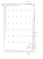
- FIG. 1 is a plan view illustrating a schematic configuration of a multilayer glass as a finished product manufactured by the multilayer glass manufacturing method of the present disclosure.
- FIG. 2 is sectional drawing which shows schematic structure of the multilayer glass as a finished product manufactured by the manufacturing method of the multilayer glass of this indication.
- FIG. 2 is a diagram showing a cross-sectional structure taken along the line X-X ′ shown in FIG.
- the multi-layer glass 1 manufactured by the manufacturing method of the present disclosure includes a pair of plate glasses disposed on the back side and a plate glass 2 on the back side and a plate glass 3 on the front side.
- a space A that can be sealed is formed between the glass sheet 2 and the glass sheet 3 by sealing the periphery with a frit seal 4 that is a sealing material.
- the spacer 6 is arrange
- the space A is made by the partition 5 which is an area
- the exhaust port 7 is divided into an exhaust port region B including the exhaust port 7 and a decompression region C which is a region other than the exhaust port region. For this reason, the reduced pressure state of the reduced pressure region C can be maintained in the multilayer glass 1 in the finished product state shown as FIG. 1 and FIG. Since the exhaust pipe connected to the exhaust port 7 is removed after the space A is divided into the exhaust port region B and the decompression region C by the partition wall 5, the exhaust port region B is spatially separated from the outside. They are connected, and air enters the exhaust port area B.
- the multilayer glass 1 manufactured by the manufacturing method according to the present embodiment maintains the reduced pressure state of the reduced pressure region C that occupies most of the space A formed between the pair of glass plates 2 and 3. Therefore, each characteristic which the double-glazed glass by which internal space was pressure-reduced, such as a heat insulation effect, a dew condensation prevention effect, and a sound insulation effect, can be exhibited.
- the exhaust pipe used for exhausting the space A is removed, as shown in FIG. 2, there is no projecting portion projecting outward on the back side of the glass sheet 2 of the multilayer glass 1.
- the inconvenience due to the presence of the protruding exhaust pipe is eliminated in handling the multilayer glass 1 during use or transportation.
- the exhaust pipe since the exhaust pipe is removed, it is possible to avoid the problem that the entire space between the glass sheets 2 and 3 of the double-glazed glass 1 is no longer decompressed when the exhaust pipe is broken.
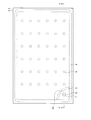
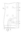
- FIGS. 3 and 4 are views for explaining a first example of a method for producing a multilayer glass 1 which is a finished product described with reference to FIGS. 1 and 2.
- FIG. 3 is a plan view showing a state before the plate glass 2 on the back side and the plate glass 3 on the front side are sealed with the frit seal 4, and
- FIG. 4 similarly shows the plate glass 2 on the back side and the plate glass 3 on the front side. It is sectional drawing which shows the state before sealing with the frit seal.
- FIG. 4 shows a cross-sectional structure taken along the line Y-Y 'shown in FIG.
- the front surface 2 a of the rear glass plate 2 that is, the peripheral portion on the surface facing the front glass plate 3.
- a frit seal 4 as a sealing material is applied in a frame shape.
- an exhaust port 7 penetrating the plate glass 2 is formed in the vicinity of the corner of the plate glass 2 on the back side.
- an exhaust pipe 8 is provided on the back surface 2 b of the plate glass 2 so as to be connected to the exhaust port 7.
- a glass exhaust pipe 8 is used as an example, and the inner diameter of the exhaust pipe 8 and the diameter of the exhaust port 7 are the same.
- the exhaust pipe 8 is connected to the exhaust port 7 by a well-known method using glass welding or molten metal as a welding member.
- a metal pipe or the like can be used in addition to the glass pipe exemplified above.
- the plate glass 2 and the plate glass 3 both have the same outer shape and thickness, but the size or thickness of one plate glass is the same as the size and thickness of the other plate glass. It does not preclude different things.
- the size of the plate glass can vary from one having a side of several centimeters depending on the application to one having a maximum length of about 2 to 3 m on one side for window glass. .
- Various types of plate glass can be used from a thickness of about 2 to 3 mm to a thickness of about 20 mm depending on the application.
- the same low melting point glass frit is used for both the frit seal 4 for sealing the pair of plate glasses 2 and 3 and the partition wall 5.
- a glass component in which Bi 2 O 3 is 70% or more, B 2 O 3 and ZnO are each 5 to 15%, and other components are 10% or less, and the main component is bismuth oxide is 60%.
- the softening point of this glass frit is 434 ° C.
- a glass frit used as the frit seal 4 and the partition 5 in addition to the bismuth frit illustrated above, a lead frit, a vanadium frit, or the like can be used.
- a sealing material made of a low melting point metal or resin can be used as the sealing material and the region forming material.
- the partition wall 5 is formed with a slit 5a which is a ventilation portion, and the partition wall 5 is discontinuous at the portion where the slit is formed. That is, the slit 5a formed in the partition wall 5 is in a state in which the portions located on both sides of the partition wall 5 in the space A formed by the pair of glass plates 2 and 3 and the frit seal 4 are spatially connected. ing.
- a plurality of spacers 6 are arranged in a matrix in the vertical and horizontal directions on the front surface 2a of the plate glass 2 located on the opposite side of the partition wall 5 from the side where the exhaust ports 7 are formed.
- the spacer 6 arranged in the multilayer glass shown in the present embodiment has a cylindrical shape with a diameter of 1 mm and a height of 100 ⁇ m, and the arrangement interval is 2 cm in the vertical and horizontal directions.
- the spacer is not limited to the illustrated cylindrical shape, and various shapes such as a prismatic shape and a spherical shape can be used.
- the size, the number of arrangement, the arrangement interval, and the arrangement pattern of the spacers are not limited to those exemplified above, and can be appropriately selected according to the size and thickness of the plate glass used.
- the spacer 6 is formed of a photocurable resin, and light having a predetermined thickness is applied to the entire front surface 2a before the frit seal 4 is applied to the front surface 2a of the plate glass 2.
- the curable resin is applied, it is formed by a photographic exposure method (photolithographic method) in which a portion that becomes the spacer 6 is cured by exposure using a mask, and then an excess portion is washed and removed.
- a photographic exposure method photolithographic method
- a spacer having a predetermined size and a cross-sectional shape can be accurately arranged at a predetermined position.
- the spacer 6 can be made inconspicuous at the time of use of the multilayer glass 1 by forming the spacer 6 with transparent photocurable resin.
- the material of the spacer 6 is not limited to the photo-curing resin exemplified above, and various materials that do not melt in the heating process described later can be used. Further, without using a photographic exposure method, a spacer formed of a material such as a metal, which is used in a conventional multilayer glass, is dispersed and arranged at a predetermined position on the front surface 2a of the plate glass 2 on the back side. Alternatively, it can be bonded. In addition, when not using the photographic exposure method for the formation and arrangement of the spacer, by using a spherical or cubic shape as the spacer, even when the orientation of the spacer is different when arranged on the surface of the plate glass, The distance between the pair of plate glasses can be accurately defined.
- a spacer is not necessarily required and it is also possible to employ
- the spacer can be formed on the inner surface of the front glass plate.
- the frit seal 4 and the partition wall 5 are not melted, the height of the frit seal 4 and the partition wall 5 is formed higher than the height of the spacer 6. For this reason, the plate glass 3 on the front side is placed on the tops of the frit seal 4 and the partition wall 5, and a gap is formed between the plate glass 3 and the tops of the spacers 6.
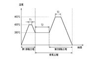
- FIG. 5 shows the setting conditions of the melting step for melting the frit seal 4 and the partition wall 5 and the exhausting step for exhausting the air in the space between the pair of plate glasses 2 and 3 in the method for producing a double-layer glass of the present embodiment. It is a figure which shows an example.
- the ultimate temperature of the melting furnace is higher than the softening temperature 434 ° C. of the glass frit used for the frit seal 4 and the partition wall 5, for example, 450 ° C. To do.
- the frit seal 4 starts to melt, the peripheral portions of the pair of glass sheets 2 and 3 are sealed, and a sealable space A is formed between the pair of glass sheets 2 and 3.
- the partition wall 5 starts to melt, and the contact portion between the partition wall 5 and the sheet glass 2 and the sheet glass 3 is welded, but the furnace temperature in the first melting step is a temperature slightly higher than the softening point temperature of the glass frit.
- the partition wall 5 is not greatly deformed, and the slit 5a formed in the partition wall 5 is not blocked.
- the maximum temperature in the first melting step is maintained at 450 ° C., and the maintenance time (require time) Is set within a range in which the slit 5a of the partition wall 5 is not blocked.
- the maintenance time (T1) in the first melting step is 10 minutes as an example.
- the air in the space A is exhausted by a vacuum pump once the temperature of the melting furnace is lowered to a temperature of 434 ° C. or lower, which is the softening point temperature of the glass frit, for example, 380 ° C.
- the exhaust process is started. Since the temperature of the melting furnace is set lower than the softening point temperature, the frit seal 4 and the partition wall 5 are not melted and deformed during the exhaust process.
- the degree of vacuum in the space A is preferably 0.1 Pa or less from the viewpoint of ensuring heat insulation as a characteristic of the double-glazed glass.
- the higher the degree of vacuum the higher the heat insulating properties of the double-glazed glass, but in order to obtain a higher degree of vacuum, it is necessary to improve the performance of the vacuum pump and lengthen the exhaust time, which increases the manufacturing cost. It becomes a factor. For this reason, it is preferable from the viewpoint of manufacturing cost that the vacuum degree that can secure the necessary characteristics as the double-glazed glass is not limited to a higher vacuum degree than necessary.
- the set temperature in the exhaust process when the set temperature in the exhaust process is lowered, it takes time to increase the temperature until the second melting process described later. For this reason, it is effective to set the set temperature at the start of the evacuation process to a temperature slightly lower than the softening point temperature of the glass frit from the viewpoint of shortening the time required for the entire melting process and the evacuation process. For example, by setting the set temperature in the exhaust process to 420 ° C. and the maintenance time (T2) to 120 minutes, the space inside the double-glazed glass can be exhausted satisfactorily.
- the temperature of the melting furnace is raised to 465 ° C. as the second melting step while the space A is being exhausted.
- the atmospheric pressure acts as an external force in the direction of narrowing the gap between the pair of plate glasses 2 and 3, so that the plate glass 2 and the plate glass 3 are pressed in the direction of narrowing the interval.
- the spacer 6 having a height of 100 ⁇ m is disposed as an example, and therefore the distance between the plate glasses 2 and 3 is defined as 100 ⁇ m, which is the height of the spacer.
- the force in the direction in which the distance between the glass plates 2 and 3 is reduced acts, so that the melted frit seal 4 and the partition wall 5 are crushed from above and below to increase the width when viewed in plan. For this reason, the pair of glass plates 2 and 3 are more firmly and securely sealed by the frit seal 4, and the slit 5 a that is a ventilation portion formed in the partition wall 5 is crushed and closed.
- the space A is divided into an exhaust port region B on the side including the exhaust port 7 and a decompression region C that is a region other than the exhaust port region.
- a mechanical pressing force can be applied to at least one of the plate glasses in the direction of narrowing the interval between the plate glasses as necessary.
- the partition wall 5 In the second melting step, it is important that the partition wall 5 is sufficiently melted as described above, and the slit 5a that is the ventilation portion is reliably closed.
- the maintenance time (T3) at the set temperature of 465 ° C. in the second melting step to 30 minutes, the partition wall 5 can reliably divide the space A into the exhaust port region B and the decompression region C. it can.
- the distance between the plate glass 2 and the plate glass 3 becomes a predetermined interval defined by the spacer 6, the slit 5 a of the partition wall 5 is completely closed, and the space A is an exhaust port region. After being completely separated into B and reduced pressure region C, the temperature of the melting furnace is lowered and the double glazing is taken out.
- the space A is divided into the exhaust port region B and the decompressed region C by the partition wall 5.
- the decompression region C is kept in a decompressed state.
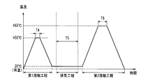
- FIG. 7 shows a melting step for melting the frit seal 4 and the partition wall 5 and an exhausting step for exhausting the air in the space A between the pair of plate glasses 2 and 3 in the method for producing a multilayer glass of the present embodiment.
- Another setting condition example is shown.
- Another setting condition shown in FIG. 7 is different from the setting condition shown in FIG. 5 and is characterized in that the multi-layer glass is lowered to room temperature after the first melting step.
- a first melting step is performed in which the frit seal 4 is melted to seal the pair of glass sheets 2 and 3 to form the space A.
- the setting conditions of the first melting step are the same as those shown in FIG. 5, 450 ° C., where the highest temperature is higher than the softening point temperature 434 ° C. of the glass frit used for the frit seal 4 and the partition wall 5.
- the maintenance time (T4) can be 10 minutes. Then, the temperature is lowered to room temperature, for example, by removing the double-glazed glass from the melting furnace.
- an exhaust process is performed in which the space A is exhausted through the exhaust pipe 8 by a vacuum pump to obtain a predetermined degree of vacuum.
- the set time (T5) of the exhaust process is, for example, 300 minutes.
- the tip of the exhaust pipe 8 is sealed with the vacuum degree of the space A being a predetermined value, for example, a vacuum degree of 0.1 Pa or less.
- a so-called chip-off is performed to seal the space A.
- the double-glazed glass with the exhaust pipe 8 being chipped off is again put into the melting furnace, and as an example, the second melting process is performed with a maximum temperature of 465 ° C. and a maintenance time (T6) of 30 minutes. .
- the temperature condition of the melting furnace can be the same as the temperature condition shown in FIG. 5, except that the space A is not evacuated in the second melting step.
- exhaust in the second melting step is not performed, but the inside of the space A is in a reduced pressure state lower than the external pressure by the exhaust step in the room temperature state. Therefore, an external force is applied to narrow the distance between the pair of glass plates 2 and 3.
- the frit seal 4 is sufficiently melted in the second melting step, the plate glasses 2 and 3 are firmly sealed, and the slits 5a of the partition walls 5 are formed. As a result, the space A is divided into an exhaust port region B and a decompression region C.
- the tip of the exhaust pipe 8 is tipped off, so that the exhaust port region after the second melting step is completed. Both B and the decompression region C are kept in a decompressed state. Thereafter, by removing the exhaust pipe 8, the exhaust port region B becomes the same state as the atmospheric pressure, while the decompression region C is kept in a decompressed state, so that the finished product shown in FIGS.
- the multilayer glass 1 can be obtained.
- the evacuation process is performed by returning the multi-layer glass to the room temperature state between the first melting process and the second melting process.
- the melting step and the evacuation step can be provided separately, and the melting furnace used in the melting step and the vacuum pump used in the evacuation step can be provided as separate manufacturing facilities.
- the structure of the melting furnace can be made simple and small, and the sealing degree of the furnace can be improved, so that it is possible to reduce the required power consumption and the heating time. it can.
- the vacuum pump can be arranged at a position away from the melting furnace that is in a high temperature state, a shielding member is arranged so that the vacuum valve of the vacuum pump, the device for chucking the exhaust pipe, etc. do not become high temperature. There is no need to take measures, and the manufacturing apparatus can be simplified.
- the second melting step since the space A is not exhausted, the external force acting in the direction of narrowing the distance between the pair of plate glasses becomes weaker than in the case of the setting conditions shown in FIG. Therefore, the application state and viscosity of the glass frit in the frit seal 4 and the partition wall 5 are sufficiently managed, and after the second melting step, the distance between the pair of glass sheets 2 and 3 becomes a predetermined one, and the partition wall 5 It is necessary to block the slit 5a so that the space A is surely divided into the exhaust region B and the decompression region C. Moreover, it is also conceivable to restrict the interval between the plate glasses to a predetermined one by applying a mechanical pressing force to at least one of the plate glasses as necessary.
- the slit 5a as the ventilation portion is provided in the partition wall 5, and the slit 5a is closed in the second melting step, thereby forming between the pair of plate glasses.
- the space A can be divided into an exhaust region B and a decompression region C.
- one slit 5a is formed at a substantially middle portion of the partition wall 5.
- the position, number, and the like of the slit are as follows. It can be determined as appropriate.
- the ventilation part formed in the partition 5 is not restricted to a slit.
- FIG. 8 is an enlarged plan view of a main part of the multilayer glass showing the partition wall of the first modified example as a configuration example of the partition wall provided with a ventilation portion different from the slit.
- the partition wall 5 of the first modified example shown in FIG. 8 is composed of two portions 5b and 5c, one end of which is continuously formed on the frit seal 4, and the other end side different from the side continuous with the frit seal 4.
- the tip of each is curved in different directions. By doing so, the gap portion 5d between the curved portions serves as a ventilation portion between the exhaust port region on the exhaust port side and the decompression region in the space A.
- the partition wall 5 is formed of a sealing material such as a low-melting point frit glass.
- the control for applying the sealing material to a predetermined position on the inner surface 2a of the plate glass 2 is performed by discharging a paste-like sealing member from the tip of the application nozzle. This is done by controlling the position of the application nozzle. For this reason, when the slit 5a having a predetermined width which is a discontinuous portion is formed in a part of the partition wall 5 which is continuously formed as shown in FIG. 3, the discharge of the sealing material from the nozzle is performed. After stopping and moving the nozzle by a predetermined amount, the sealing material is discharged from the nozzle again.
- the end portion on the opposite side to the connecting portion with the frit seal 4 is curved in different directions to provide a predetermined interval, and the interval portion 5d.
- the width of the gap portion 5d between the curved portions of the applied glass frit, the length of the portion where the application regions overlap from two directions, and the formation width of the partition walls 5b and 5c at that portion, the viscosity of the glass frit and the application The height can be determined as appropriate in consideration of the width of the partition wall 5 in a state of being crushed in the second melting step in which the partition wall is melted to block the ventilation portion.
- the opposite side edge part of the partition 5 is formed as a linear part which goes to a mutually different direction, for example, at least one part of this linear part is It has a configuration in which partition walls that are continuously formed are arranged at a predetermined interval, such as being configured to be arranged substantially parallel to each other at a predetermined interval, and this predetermined interval portion is crushed in the second melting step Various configurations that serve as a ventilation portion to be closed can be employed.
- FIG. 9 is an enlarged plan view of an essential part of the double-glazed glass showing the partition wall of the second modified example, which is still another configuration example of the partition wall provided with the ventilation portion.
- the partition wall 5 of the second modification shown in FIG. 9 has two partial partition walls 5e, one end of which is connected to the frit seal 4, and the other end different from the side of the two partial partition walls 5e continuous to the frit seal 4.
- a discontinuous portion 5f whose side is a gap portion is formed, and a seal portion 5g longer than the length of the discontinuous portion 5f is formed on one side surface portion of the discontinuous portion 5f.
- a fixed length longer than the slit 5a width of the partition wall 5 shown in FIG. 3 at the intermediate portion is the coating width of the partial partition wall 5e.
- a longer discontinuous portion 5f is formed.
- the length of the discontinuous portion 5f formed in the intermediate portion can be formed longer than the width of the slit 5a shown in FIG. Since the sealing portion 5g to be closed is disposed in the vicinity of the discontinuous portion 5f, the accuracy required for the length of the discontinuous portion 5f is not so high. For this reason, even if the coating formation process of the partition wall 5 is simpler than the method of forming the slit 5a shown in FIG. A partition wall 5 having a ventilation portion can be formed.
- the length of the discontinuous portion 5f and the length of the seal portion 5g and the distance between the partial partition wall 5e and the seal portion 5g are the same as those of the seal member that forms the partition wall 5. It can be appropriately determined in consideration of the material, the coating formation method, the coating height, the temperature condition in the second melting step, the width of the partial partition wall 5e, and the like.
- the partition wall of the first modification example shown in FIG. 8 or the partition wall of the second modification example shown in FIG. 9 When the partition wall of the first modification example shown in FIG. 8 or the partition wall of the second modification example shown in FIG. 9 is used, the ventilation part formed in the partition wall is blocked and the space A is filled with the exhaust port region B. As shown in FIG. 10, the partition wall 5 that is divided into the decompression region C has a wider portion 5 h where the ventilation portion is blocked. When the width of the partition wall 5 becomes too wide, the partition wall 5 is easily visually recognized when the multi-layer glass 1 is completed. Moreover, there is a possibility that the problem that the partition wall 5 that has melted and expanded leaks out from the exhaust port 7 to the outside. For this reason, it is preferable to sufficiently control the width of the portion 5 h of the partition wall 5 in a state where the ventilation portion is closed by adjusting the conditions for coating and forming the partition wall 5.
- a frit seal as a sealing material and a partition wall as a region forming material are formed using a low-melting glass frit of the same material.
- a low-melting glass frit of the same material Has been described as an example.
- the frit seal and the partition are not limited to those using the same glass frit.
- a glass frit having a melting temperature higher than that of a frit seal as a sealing material can be used as a partition as a region forming material.
- the melting temperature of the glass frit used as the frit seal is different from the melting temperature of the glass frit used as the partition wall, and further, the melting temperature of the first melting step for melting the frit seal and sealing the pair of plate glasses is set to the melting temperature of the frit seal.
- the melting temperature in the second melting step in which the partition wall is melted and the space A is divided into the exhaust port region and the decompression region is set to a temperature higher than the melting temperature of the partition wall.
- the sealing material and the region forming material can be made of a sealing member other than a glass frit and having different melting conditions.
- the sealing material and the region forming material are formed by a sealing member that melts under different conditions, and only the sealing material is melted in the first melting step, and the region forming material is melted in the second melting step.
- the region forming material is undesirably melted in the first melting step, the size of the ventilation portion is narrowed, the exhaust efficiency inside the space is reduced, or in the worst case, the first melting It is possible to avoid an unexpected situation where the ventilation portion is blocked in the process and the decompression region cannot be sufficiently decompressed.
- both the frit seal as the sealing material and the partition wall as the region forming material are formed of low melting point glass frit
- the components and size of the glass powder used for the glass frit and the mixed metal powder are used.
- the melting temperature of the glass frit can be adjusted by adjusting the content and the like, and by adjusting the concentration and content of the resin component used as the solvent.
- the manufacturing method of the multilayer glass concerning 2nd Embodiment is the partition 5 which is an area
- the point which lowers the formation height of this differs from the manufacturing method of the multilayer glass concerning the above-mentioned 1st Embodiment.
- members that are the same as those in the first embodiment are given the same reference numerals, and detailed descriptions thereof may be omitted as appropriate.
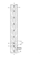
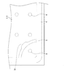
- FIG. 11 and FIG. 12 are diagrams for explaining a method for producing a multilayer glass as the second embodiment.
- FIG. 11 is a plan view showing a state before the plate glass 2 on the back side and the plate glass 3 on the front side are sealed with the frit seal 4.
- FIG. 12 is a cross-sectional view showing a state before the rear glass plate 2 and the front glass plate 3 are sealed with the frit seal 4.
- FIG. 12 shows a cross-sectional configuration taken along the line Z-Z 'shown in FIG.
- FIG. 11 is a drawing corresponding to FIG. 3 in the first embodiment
- FIG. 12 is a drawing corresponding to FIG. 4 in the first embodiment.
- the front surface 2 a of the rear glass plate 2 that is, the peripheral portion on the surface facing the front glass plate 3.
- a frit seal 4 as a sealing material is applied in a frame shape.
- an exhaust port 7 penetrating the plate glass 2 is formed in a corner portion of the plate glass 2 on the back side.
- an exhaust pipe 8 connected to the exhaust port 7 is provided on the back surface 2 b of the plate glass 2.
- a partition wall 5 as a region forming material is formed so as to surround the exhaust port 7 together with the frit seal 4.
- the frit seal 4 for sealing the pair of glass plates 2 and 3 and the partition wall 5 are both the same low melting point glass frit, but the application height of the frit seal 4 is 1 mm as an example.
- the coating height of the partition wall 5 is 0.5 mm as an example, which is lower than the coating height of the frit seal 4.
- the coating height of the frit seal 4 and the coating height of the partition wall 5 are appropriately set within a range in which melting of the frit seal 4 and the partition wall 5 can be controlled in the step of dividing the space between the plate glasses 2 and 3 by the partition wall 5 described later. Can be determined.
- the application height of the frit seal 4 is 0.5 mm with respect to the height of the spacer 6 of 0.1 mm.
- the width can be 5 mm
- the coating height of the partition wall 5 can be 0.2 mm
- the coating width can be 3 mm.
- the paste used to form the frit seal 4 and the partition wall 5 include 70% or more of Bi 2 O 3, 5 to 15% of B 2 O 3 and ZnO, respectively, as exemplified in the first embodiment.
- glass component whose main component is bismuth oxide whose component is 10% or less, further 20 to 30% zinc silica oxide, mixture of organic substances such as ethyl cellulose, terpineol, polyisobutyl methacrylate
- a bismuth-based seal frit paste containing 5 to 15% and having a softening point of 434 ° C. can be used.
- the state shown in FIG. 12 is a state before the frit seal 4 and the partition wall 5 are melted, so that the front glass plate 3 is placed on the upper part of the frit seal 4 having a higher coating height. ing.
- the first melting step is performed under the set conditions shown in FIG. 5 exemplified in the first embodiment.
- the frit seal 4 is melted and the plate glass 2 and the plate glass 3 are sealed. Further, the frit seal 4 is melted by passing through the first melting step, and the height of the frit seal 4 is lowered and the width is expanded.
- interval of the plate glass 3 of the front side and the plate glass 2 of the back side is narrowed a little, as demonstrated in 1st Embodiment, the highest ultimate temperature in a 1st fusion
- the space is reduced to a vacuum of 0.1 Pa or less, but as described above, between the plate glass 3 and the upper end of the partition wall 5. Since a gap remains in the interior space A, the entire internal space A has a predetermined degree of vacuum.
- a second melting step is performed in which the reached temperature is 465 ° C., which is higher than the first melting step.
- the frit seal 4 is further melted by this second melting step. Since the internal space A is in an exhausted state, an external force in a direction in which the distance between the glass sheet 3 and the glass sheet 2 is reduced acts strongly, and the distance between the glass sheets 2 and 3 is reduced until it is regulated by the height of the spacer 6. .
- the partition wall 5 comes into contact with both the plate glass 2 and the plate glass 3, and the partition wall 5 causes the space A to be the exhaust port region B on the exhaust port side and the decompression region C other than the exhaust port region. And divided. Also in this embodiment, in the second melting step, a mechanical pressing force can be applied to at least one of the plate glasses in the direction of narrowing the interval between the plate glasses as necessary.
- the subsequent steps are the same as in the case of the first embodiment, and the exhaust pipe 8 is removed while being removed from the vacuum pump and the exhaust hole region B is at the same atmospheric pressure as the outside air.
- the decompression state is maintained in the decompression region C, the multilayer glass 1 in the finished product state shown in FIGS. 1 and 2 can be obtained in the same manner as in the manufacturing method of the first embodiment.
- the coating height of the partition wall 5 as the region forming material lower than the coating height of the frit seal 4 as the sealing material,
- the entire internal space formed between the pair of sealed glass plates 2 and 3 can be divided into an exhaust port region and a reduced pressure region after being brought into a predetermined reduced pressure state.
- the frit seal 4 and the partition wall 5 are exemplified by using the same low melting point glass frit.
- the frit seal 4 has a melting temperature of the partition wall 5.
- a material having a temperature lower than the melting temperature of the low-melting glass frit forming the film can be used.
- the distance between the plate glass 3 and the plate glass 2 outside the frit seal 4 application portion is provided so as to prevent the value from becoming less than or equal to a predetermined value, and this stopper is operated in the first melting step to maintain a predetermined interval. In the second melting step, the stopper is removed, and the plate glass 3 and the plate glass 2 It is also possible to adopt a method in which the interval is set to a predetermined interval defined by the spacer 6.
- the temperature of the sealing glass was lowered to room temperature after the first melting process, and the exhaust process was performed outside the melting furnace, as in the first embodiment.
- Another setting condition shown as FIG. 7 in the first embodiment in which the second melting step is performed later can be adopted.
- the region forming material and the exhaust port region including the exhaust port are It can divide
- the sealing material and the region forming material those using a member that melts and deforms when the temperature rises, such as a glass frit, are exemplified.
- a member that melts and deforms when the temperature rises such as a glass frit
- Various members that are deformed and solidified into a predetermined shape by light rays such as ultraviolet rays or other stimuli can be used.
- the high temperature process including the first melting step and the second melting step described in the above embodiment is not necessary, and the production facility for the double-glazed glass can be greatly simplified.
- the ventilation portion formed in the region forming material only the ventilation portion as a planar configuration such as a slit or a formation interval portion of the region forming material is illustrated, but the region forming material Depending on the material and its deformation and solidification method, it is possible to provide a through-hole penetrating the region forming material and use it as a ventilation portion.
- the lead time of a melting process and an exhaust process can be reduced.
- the timing at which the ventilation part formed in the region forming material is blocked is accurately controlled, and the gap between the pair of plate glasses is controlled. It is extremely important to control so that the decompression region formed by dividing the space is sufficiently decompressed.
- the partition as the region forming material is formed of a material having a softening point different from that of the frit seal as the sealing material.
- the portions other than the sealing material arranged around the pair of plate glasses are all made of the region forming material in the same state.
- the method for producing a multilayer glass according to the present disclosure as a method for maintaining the internal space A as one continuous space after the first melting step, only a part of the region forming material is used as a sealing material and a softening point.
- the vent portions can be formed in the different material portions and the other portions can be formed of the same material as the sealing material.
- the coating height of only a part of the region forming material can be set to a coating height lower than that of the sealing material, and the coating height of other portions can be set to the same coating height as that of the sealing material. Further, both the material of the region forming material and the coating height can be different from the sealing material.
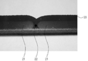
- FIG. 13 is a diagram for explaining the state of the region forming material in the finished product state of the multilayer glass manufactured by the manufacturing method according to the present disclosure.
- FIG. 13 is a photograph of a sample in which the low-melting glass frit 21 applied through the slits 22 at a predetermined interval is melted by the melting process and the melted portion 23 closes the slits.
- the paste exemplified in the first and second embodiments is used, and a paste having a coating width of 5 mm, a slit width of 2 mm, and a coating height of 0.5 mm is put in a melting furnace at 465 ° C. It is formed through a melting process for 30 minutes.
- the plate glass two soda lime glasses having a thickness of 3 mm are used, and no external force is applied to narrow the distance between the pair of plate glasses at the time of melting.
- a glass frit 21 is formed in the peripheral region of the plate glass through the slit 22 so as to facilitate photography.
- the glass frit after melting is in a state in which a relatively light-colored portion 21 that has been previously formed by coating and a relatively dark colored portion 23 that has been melted and solidified can be discriminated.
- the inventors have confirmed by enlarging with a microscope that the low-melting glass of the part that had been applied in advance had a fine granular pattern, whereas the low-melting glass of the part that once melted and flowed was A thin line pattern was confirmed.
- This pattern is considered to be the observation of glass fine particles or bubbles contained in the low melting point glass frit paste, and it can be considered that the amount of movement from the original application position became the difference in the pattern. It is considered that such a difference in the surface state appears as a difference in color that can be observed with the naked eye.
- the low melting point glass frit is in a state where the surface state is different between the pre-coated part and the part once melted and fluidized and then solidified again, resulting in a finished multilayer glass.
- the coating height of the low melting point glass frit is changed, it appears as a difference in the cross-sectional shape in the state of the finished product, in particular, the width of the cross section and the extent of the portion in contact with the plate glass.
- the double-glazed glass produced using the method for producing double-glazed glass according to the present disclosure includes an exhaust port area that is an external pressure and a reduced pressure area in which a reduced pressure state is maintained, By observing the state of the region forming material between the two regions, it can be distinguished from a multilayer glass produced by another method.
- a predetermined portion of the sealing material or the region forming material is laser
- a laser sealing method in which heat welding is performed.
- a predetermined heat is applied from the outside and the sealing material or region forming material in a specific location is welded selectively. It becomes easy to make. As a result, it can be expected that the melting control in the manufacturing process in which only the sealing material is first welded and then the region forming material is melted is performed more reliably.
- the internal space is evacuated and the region forming material is melted by a laser sealing method, and the internal space is divided into an exhaust port region and a reduced pressure region, It becomes possible to produce a multilayer glass at a low cost using a simple apparatus.
- the spacer is disposed in the inner region where the sealing material is formed and the gap between the pair of glass sheets is regulated.
- the height regulating member corresponding to the spacer is sealed. It can also be arranged in the formation part of the dressing.
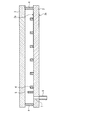
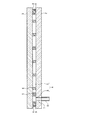
- FIG. 14 shows that the region forming material melts and the internal space is divided when the glass bead that is the height regulating member having the same height as the spacer is arranged in the formation region of the frit seal that is the sealing material. It is sectional drawing which shows the state.
- FIG. 14 shows the double-glazed glass in a state where the frit seal and the partition walls are completely melted, as in FIG. 6 used for the description of the first embodiment.
- spherical glass beads 9 having the same diameter as the height of the spacer 6 are arranged in the formation part of the frit seal 4, thereby forming the part where the spacer 6 is arranged and the glass frit 4. It is possible to eliminate the difference in height of the gap between the pair of glass plates 2 and 3 in the peripheral portion. By doing in this way, since it can prevent more reliably that the glass plates 2 and 3 curve in the state of a finished product, the stress which remains on the glass plates 2 and 3 can be reduced and the intensity
- the distance between the glass sheets 2 and 3 becomes narrower than a predetermined distance, so that the frit seal 4 is crushed and its width is widened, and the user can easily see it. The problem can be avoided.
- a height regulating member is arranged in advance at the place where the frit seal 4 is formed at the same time as the spacer by a spraying method similar to the arrangement method of the spacer 6 or a photographic exposure method, and the frit seal 4 is overlaid on the height regulating member. It can also be formed by coating.
- the height regulating member described with reference to FIG. 14 is arranged at a portion where the sealing material is formed, so that the appearance of the multilayer glass is impaired by being visually recognized by the user like a spacer.
- a columnar member having a relatively large area or a continuous member having a predetermined length in the circumferential direction of the partition-like plate glass can be used as the height regulating member.
- the above-described photographic exposure method is excellent as a method for arranging and forming the height regulating member having a large area when viewed in plan. Further, depending on the size of the multilayer glass, the thickness of the plate glass to be used, etc., it is possible to produce a multilayer glass in which only the height regulating member is disposed and no spacer is disposed.
- the number of exhaust ports is not restricted to one, In particular, in the case of a multi-layer glass having a large area, it is possible to form two or more exhaust ports in consideration of exhaust efficiency.
- the region forming material is disposed so as to surround each exhaust port, and the internal space is divided into a plurality of exhaust port regions and one or possibly a plurality of decompression regions.
- an exhaust port can also be formed in both plate glass.
- a predetermined gap is provided in the sealing material formed in the peripheral portion of the plate glass, and the gas inside the space can be exhausted by using this gap as the exhaust port. it can.
- the space between a pair of plate glasses is divided by a region forming material, so that it is not necessary to keep the exhaust region in a reduced pressure state in the finished product, and the exhaust port is closed. There is no need to do.
- a method of forming a discontinuous portion as shown in the region forming material as a ventilation portion on the sealing material, or a cylindrical member instead of spherical glass beads as the above-described height regulating member is used as the sealing material. It is also possible to use the internal space of the cylindrical member as an exhaust port by disposing it in the sealing material so as to penetrate. Note that a plurality of exhaust ports formed in the sealing material can be arranged, and exhaust ports can be formed in both the plate glass and the sealing material.
- the method of connecting the exhaust pipe to the exhaust port and depressurizing the internal space via the exhaust pipe has been described.
- the exhaust pipe By using the exhaust pipe, it becomes easy to connect to the vacuum pump, and the space between the pair of plate glasses can be reduced by a conventionally established exhaust method.
- the tube is not essential.
- the sealed plate glass and the vacuum pump are hermetically connected using a ring-shaped member having a predetermined flexibility that can be in close contact with the surface of the plate glass around the portion where the exhaust port is formed.
- the internal space can be decompressed without using the exhaust pipe.
- a double-glazed glass produced by the method for producing double-glazed glass of the present disclosure various optical functions such as antireflection and absorption of ultraviolet rays, or functions such as heat insulating properties are imparted to the plate glass, and organic or inorganic It is possible to add and apply the already established technology related to the double-glazed glass that forms a functional film.
- a thin film made of an oxide such as tin oxide (SnO 2 ), indium tin oxide (ITO), zinc oxide or the like is formed on the inner surface or outer surface of at least one plate glass constituting the multilayer glass by CVD (chemical vapor).
- An infrared reflection film that strongly reflects light in the infrared region can be provided by forming the film by a known method such as a deposition method or by alternately laminating silver and an oxide film by a sputtering apparatus. As a result, the heat insulating properties can be improved. Moreover, in this case, a laminated glass having a further excellent heat insulating property can be obtained by providing a spacer having a hollow structure or a spacer formed from a member having low thermal conductivity.
- a getter material that can improve the degree of vacuum can be disposed in the internal space A of the laminated glass. Furthermore, as a plate glass constituting the multilayer glass, a multilayer glass having a curved shape as a whole can be realized by using curved glass curved in one direction or a plurality of directions.
- the multilayer glass manufactured by the manufacturing method of the present disclosure for example, the multilayer glass manufactured by the manufacturing method of the present disclosure is laminated with a multilayer glass in which an inert gas is sealed between plate glasses.
- the multi-layer glass produced by the method for producing multi-layer glass of the present disclosure described above can be used favorably for window glass and the like as eco-glass having a high heat insulating effect and easy handling.
- the double-glazed glass manufactured by the double-glazed glass manufacturing method of the present disclosure on the door portion of the refrigerator or freezer, the inside of the refrigerator or freezer can be utilized without taking advantage of the high heat insulation effect. It can be used for home use or business use.
- the technology for dividing the glass sheet while maintaining the reduced pressure in the exhausted space in the present disclosure is used for a display device that exhausts the interior of a predetermined space, such as a plasma display panel or a fluorescent display device, other than the multilayer glass.
- a display device that does not have a projection such as an exhaust pipe in a finished product state.
- the multilayer glass manufacturing method of the present disclosure is useful as a method capable of manufacturing a multilayer glass that is easy to handle by a simple method.
Abstract
Description
最初に、図1および図2を用いて、本実施形態の複層ガラスの製造方法によって製造された複層ガラスの構成を説明する。
本開示の第2の実施形態にかかる複層ガラスの製造方法について、図面を参照して説明する。
Claims (12)
- 所定間隔を隔てて対向配置された一対の板ガラスの周辺部を封着材で封着して前記板ガラスの間に密閉可能な空間を形成し、排気口から排気することによって前記空間内を減圧状態とする複層ガラスの製造方法であって、
前記空間内を減圧状態とした後に、前記空間内に配置された領域形成材によって前記空間を前記排気口が含まれる排気口領域と前記排気口領域以外の減圧領域とに分割することを特徴とする複層ガラスの製造方法。 - 前記領域形成材は、前記空間が形成された状態で前記排気口領域と前記減圧領域とを接続する通気部を有し、前記空間内を減圧状態とした後に前記通気部が閉塞されて前記空間を前記排気口領域と前記減圧領域とに分割する請求項1に記載の複層ガラスの製造方法。
- 前記通気部が、断続的に形成された前記領域形成材の不連続部分であり、前記空間内を減圧状態とした後に前記領域形成材を溶融させて前記不連続部分を連続させる請求項2に記載の複層ガラスの製造方法。
- 溶融前の前記領域形成材の形成高さを、溶融前の前記封着材の形成高さよりも低く形成し、
前記封着材が溶融して前記一対の板ガラスが封着された状態で前記空間内を減圧状態とし、その後前記一対の板ガラスの間隔を狭くして前記領域形成材によって前記空間を前記排気口領域と前記減圧領域とに分割する請求項1に記載の複層ガラスの製造方法。 - 前記領域形成材の溶融温度が前記封着材の溶融温度よりも高く、前記封着材が溶融する温度で前記一対の板ガラスを封着して前記空間を形成し、前記空間内を減圧状態とした後に、前記領域形成材が溶融する温度で前記領域形成材を溶融させて前記空間を前記排気口領域と前記減圧領域とに分割する請求項1~4のいずれかに記載の複層ガラスの製造方法。
- 溶融炉内において前記封着材を溶融させて前記空間を形成した後、前記溶融炉から取り出して前記空間を減圧状態とした後、再び溶融炉内において前記領域形成材を溶融させて前記空間を前記排気口領域と前記減圧領域とに分割する請求項1~5のいずれかに記載の複層ガラスの製造方法。
- 前記排気口が、前記一対の板ガラスの少なくともいずれか一方に形成されている請求項1~6のいずれかに記載の複層ガラスの製造方法。
- 前記排気口に接続された排気管を介して前記空間内を減圧状態とし、前記空間を前記排気口領域と前記減圧領域とに分割した後に前記排気管を除去する請求項1~7のいずれかに記載の複層ガラスの製造方法。
- 前記封着材および前記領域形成材がガラスフリットである請求項1~8のいずれかに記載の複層ガラスの製造方法。
- 前記一対の板ガラスのいずれか一方の表面に、前記一対の板ガラスの間隙を規定するスペーサーが配置されている請求項1~9のいずれかに記載の複層ガラスの製造方法。
- 前記封着材形成部分に、前記一対の板ガラスの間隙を規定する高さ規制部材が配置されている請求項1~10のいずれかに記載の複層ガラスの製造方法。
- 前記スペーサーまたは前記高さ規制部材の少なくともいずれか一方が、写真露光法により形成されたものである請求項10または11に記載の複層ガラスの製造方法。
Priority Applications (13)
| Application Number | Priority Date | Filing Date | Title |
|---|---|---|---|
| PL17168000T PL3225604T3 (pl) | 2012-05-18 | 2013-05-16 | Sposób produkcji szyb zespolonych |
| IN9649DEN2014 IN2014DN09649A (ja) | 2012-05-18 | 2013-05-16 | |
| AU2013260930A AU2013260930B2 (en) | 2012-05-18 | 2013-05-16 | Production method of multiple panes |
| BR112014028689-2A BR112014028689B1 (pt) | 2012-05-18 | 2013-05-16 | método de produção de chapas múltiplas |
| KR1020147035207A KR101688297B1 (ko) | 2012-05-18 | 2013-05-16 | 복층 유리의 제조 방법 |
| CN201380025971.5A CN104302593A (zh) | 2012-05-18 | 2013-05-16 | 多层玻璃的制备方法 |
| JP2014515501A JP5821010B2 (ja) | 2012-05-18 | 2013-05-16 | 複層ガラスの製造方法 |
| CA2873960A CA2873960C (en) | 2012-05-18 | 2013-05-16 | Production method of multiple panes |
| EP13791335.6A EP2851351B1 (en) | 2012-05-18 | 2013-05-16 | Method for manufacturing multiple-pane glass |
| EP17168000.2A EP3225604B1 (en) | 2012-05-18 | 2013-05-16 | Production method of multiple panes |
| US14/546,992 US10024098B2 (en) | 2012-05-18 | 2014-11-18 | Production method of multiple panes |
| AU2016203380A AU2016203380B2 (en) | 2012-05-18 | 2016-05-24 | Production method of multiple panes |
| US15/981,746 US11021906B2 (en) | 2012-05-18 | 2018-05-16 | Production method for forming multiple pane and multiple panes |
Applications Claiming Priority (2)
| Application Number | Priority Date | Filing Date | Title |
|---|---|---|---|
| JP2012114979 | 2012-05-18 | ||
| JP2012-114979 | 2012-05-18 |
Related Child Applications (1)
| Application Number | Title | Priority Date | Filing Date |
|---|---|---|---|
| US14/546,992 Continuation US10024098B2 (en) | 2012-05-18 | 2014-11-18 | Production method of multiple panes |
Publications (1)
| Publication Number | Publication Date |
|---|---|
| WO2013172033A1 true WO2013172033A1 (ja) | 2013-11-21 |
Family
ID=49583461
Family Applications (1)
| Application Number | Title | Priority Date | Filing Date |
|---|---|---|---|
| PCT/JP2013/003128 WO2013172033A1 (ja) | 2012-05-18 | 2013-05-16 | 複層ガラスの製造方法 |
Country Status (19)
| Country | Link |
|---|---|
| US (2) | US10024098B2 (ja) |
| EP (2) | EP3225604B1 (ja) |
| JP (5) | JP5821010B2 (ja) |
| KR (1) | KR101688297B1 (ja) |
| CN (2) | CN104302593A (ja) |
| AU (2) | AU2013260930B2 (ja) |
| BR (1) | BR112014028689B1 (ja) |
| CA (1) | CA2873960C (ja) |
| DK (1) | DK3225604T3 (ja) |
| ES (1) | ES2730207T3 (ja) |
| HU (1) | HUE043865T2 (ja) |
| IN (1) | IN2014DN09649A (ja) |
| LT (1) | LT3225604T (ja) |
| MY (1) | MY171346A (ja) |
| PL (1) | PL3225604T3 (ja) |
| PT (1) | PT3225604T (ja) |
| SI (1) | SI3225604T1 (ja) |
| TR (1) | TR201908104T4 (ja) |
| WO (1) | WO2013172033A1 (ja) |
Cited By (22)
| Publication number | Priority date | Publication date | Assignee | Title |
|---|---|---|---|---|
| JP2016069232A (ja) * | 2014-09-30 | 2016-05-09 | パナソニックIpマネジメント株式会社 | ガラスパネルユニット、ガラスパネルユニットの組立て品、ガラスパネルユニットの製造方法 |
| JP2016108799A (ja) * | 2014-12-04 | 2016-06-20 | パナソニックIpマネジメント株式会社 | ガラスパネルユニット |
| JP2016175811A (ja) * | 2015-03-20 | 2016-10-06 | パナソニックIpマネジメント株式会社 | 真空ガラスパネルの製造方法 |
| WO2017056422A1 (ja) * | 2015-09-29 | 2017-04-06 | パナソニックIpマネジメント株式会社 | ガラスパネルユニットおよびガラス窓 |
| WO2017056418A1 (ja) * | 2015-09-29 | 2017-04-06 | パナソニックIpマネジメント株式会社 | ガラスパネルユニット,これを備えたガラス窓、及びガラスパネルユニットの製造方法 |
| JP2017128456A (ja) * | 2016-01-18 | 2017-07-27 | 日立化成株式会社 | 複層ガラス、及びその製造方法 |
| WO2017169252A1 (ja) * | 2016-03-31 | 2017-10-05 | パナソニックIpマネジメント株式会社 | ガラスパネルユニットの製造方法 |
| WO2017170076A1 (ja) * | 2016-03-31 | 2017-10-05 | パナソニックIpマネジメント株式会社 | ガラスパネルユニットの製造方法、建具の製造方法、ガラスパネルユニットの製造装置、及びガラスパネルユニット |
| WO2017169353A1 (ja) * | 2016-03-31 | 2017-10-05 | パナソニックIpマネジメント株式会社 | ガラスパネルユニット及びこれを備える建具の製造方法 |
| WO2018043376A1 (ja) * | 2016-08-31 | 2018-03-08 | パナソニックIpマネジメント株式会社 | ガラスパネルユニットおよびガラス窓 |
| WO2018062124A1 (ja) * | 2016-09-28 | 2018-04-05 | パナソニックIpマネジメント株式会社 | ガラスパネルユニットの製造方法およびガラス窓の製造方法 |
| WO2018062072A1 (ja) * | 2016-09-30 | 2018-04-05 | パナソニックIpマネジメント株式会社 | ガラスパネルユニットの製造方法、ガラス窓の製造方法、およびガラスパネルユニット |
| JPWO2017169731A1 (ja) * | 2016-03-31 | 2019-02-14 | パナソニックIpマネジメント株式会社 | ガラスパネルユニット |
| US10378272B2 (en) | 2014-09-30 | 2019-08-13 | Panasonic Intellectual Property Management Co., Ltd. | Glass panel unit, temporary assembly of glass panel unit, completed assembly of glass panel unit, method for manufacturing glass panel unit |
| WO2019188312A1 (ja) * | 2018-03-30 | 2019-10-03 | パナソニックIpマネジメント株式会社 | ガラスパネルユニットの製造方法及びガラス窓の製造方法 |
| US10443298B1 (en) | 2018-07-25 | 2019-10-15 | Kyun Jang Chin | Vacuum insulated glass panel with structured pillar unit |
| WO2019208002A1 (ja) * | 2018-04-27 | 2019-10-31 | パナソニックIpマネジメント株式会社 | ガラスパネルユニット、ガラス窓、ガラスパネルユニットの製造方法及びガラス窓の製造方法 |
| WO2020003830A1 (ja) | 2018-06-29 | 2020-01-02 | パナソニックIpマネジメント株式会社 | ガラスパネルユニットの製造方法 |
| US10570476B2 (en) | 2015-03-27 | 2020-02-25 | Jfe Steel Corporation | High-strength steel sheet and production method therefor |
| WO2020203009A1 (ja) * | 2019-03-29 | 2020-10-08 | パナソニックIpマネジメント株式会社 | ガラスパネルユニット及びガラスパネルユニットの製造方法 |
| JPWO2020209033A1 (ja) * | 2019-04-12 | 2020-10-15 | ||
| US11549305B2 (en) * | 2018-05-31 | 2023-01-10 | Panasonic Intellectual Property Management Co., Ltd. | Glass panel unit assembly, and method for manufacturing glass panel unit |
Families Citing this family (26)
| Publication number | Priority date | Publication date | Assignee | Title |
|---|---|---|---|---|
| CA2916037C (en) * | 2013-05-27 | 2021-04-06 | Michael John BOYDEN | A double-glazed window or door assembly |
| US20150262902A1 (en) | 2014-03-12 | 2015-09-17 | Invensas Corporation | Integrated circuits protected by substrates with cavities, and methods of manufacture |
| US9366071B1 (en) * | 2014-12-03 | 2016-06-14 | Peter Petit | Low-friction spacer system for vacuum insulated glass |
| EP3268567A1 (en) * | 2015-03-12 | 2018-01-17 | 3M Innovative Properties Company | Vacuum glazing pillars for insulated glass units and insulated glass units therefrom |
| KR20160123658A (ko) | 2015-04-16 | 2016-10-26 | 최융재 | 속이 빈 구(Empty Sphere)를 이용한 진공 복층유리의 제조 방법 |
| JP7126313B2 (ja) | 2016-05-11 | 2022-08-26 | 富士電機株式会社 | 紙幣処理装置の収納構造 |
| US20170159996A1 (en) * | 2015-12-08 | 2017-06-08 | Whirlpool Corporation | Vacuum insulation structures with a filler insulator |
| JPWO2017169253A1 (ja) * | 2016-03-31 | 2019-02-14 | パナソニックIpマネジメント株式会社 | ガラスパネルユニット及びガラス窓 |
| WO2018062140A1 (ja) * | 2016-09-30 | 2018-04-05 | パナソニックIpマネジメント株式会社 | ガラスパネルユニット、ガラス窓およびガラスパネルユニットの製造方法 |
| USD837411S1 (en) * | 2016-12-09 | 2019-01-01 | Panasonic Intellectual Property Management Co., Ltd. | Vacuum-insulated glass plate |
| US10002844B1 (en) | 2016-12-21 | 2018-06-19 | Invensas Bonding Technologies, Inc. | Bonded structures |
| USD837412S1 (en) * | 2017-01-20 | 2019-01-01 | Panasonic Intellectual Property Management Co., Ltd. | Vacuum-insulated glass plate |
| WO2018147940A1 (en) | 2017-02-09 | 2018-08-16 | Invensas Bonding Technologies, Inc. | Bonded structures |
| EP3583080B1 (en) * | 2017-02-17 | 2024-01-03 | VKR Holding A/S | Top frit heat treatment |
| EP3363983B1 (en) * | 2017-02-17 | 2021-10-27 | VKR Holding A/S | Vacuum insulated glazing unit |
| US10508030B2 (en) | 2017-03-21 | 2019-12-17 | Invensas Bonding Technologies, Inc. | Seal for microelectronic assembly |
| JP2018188341A (ja) * | 2017-05-10 | 2018-11-29 | 株式会社日立製作所 | 複層ガラス及びその製造方法 |
| US11380597B2 (en) * | 2017-12-22 | 2022-07-05 | Invensas Bonding Technologies, Inc. | Bonded structures |
| US10923408B2 (en) | 2017-12-22 | 2021-02-16 | Invensas Bonding Technologies, Inc. | Cavity packages |
| WO2019207970A1 (ja) * | 2018-04-26 | 2019-10-31 | パナソニックIpマネジメント株式会社 | ガラスパネルユニットの組立て品、ガラスパネルユニットの製造方法 |
| US11004757B2 (en) | 2018-05-14 | 2021-05-11 | Invensas Bonding Technologies, Inc. | Bonded structures |
| JP7063740B2 (ja) | 2018-06-18 | 2022-05-09 | 日本板硝子株式会社 | 真空ガラスパネル |
| JP7026330B2 (ja) * | 2018-06-26 | 2022-02-28 | パナソニックIpマネジメント株式会社 | ガラスパネルユニットの製造方法 |
| CN113939485A (zh) | 2019-04-12 | 2022-01-14 | 旭硝子欧洲玻璃公司 | 用于vig组件的特定经涂覆的玻璃 |
| CN113074509A (zh) * | 2020-01-06 | 2021-07-06 | 青岛海尔电冰箱有限公司 | 真空绝热体及冰箱 |
| EP4326551A1 (en) | 2021-04-21 | 2024-02-28 | AGC Glass Europe | Novel lamination process to produce laminated vacuum insulating glazing assembly |
Citations (7)
| Publication number | Priority date | Publication date | Assignee | Title |
|---|---|---|---|---|
| JPH07508967A (ja) * | 1992-01-31 | 1995-10-05 | ザ ユニバーシテイ オブ シドニイ | 熱絶縁ガラスパネルの改良 |
| JPH102161A (ja) | 1996-06-17 | 1998-01-06 | Nippon Sheet Glass Co Ltd | 真空複層ガラス及びその製造方法 |
| JPH11311069A (ja) | 1998-04-30 | 1999-11-09 | Nippon Sheet Glass Co Ltd | ガラスパネル |
| JP2000063157A (ja) * | 1998-08-11 | 2000-02-29 | Nippon Sheet Glass Co Ltd | ガラスパネル及びその製造方法 |
| JP2000510281A (ja) * | 1996-12-12 | 2000-08-08 | キャンデセント・テクノロジーズ・コーポレイション | 封止構造体に対するギャップ跳躍 |
| JP2002008569A (ja) * | 2000-06-27 | 2002-01-11 | Canon Inc | 画像形成装置 |
| JP2009167041A (ja) * | 2008-01-15 | 2009-07-30 | Panasonic Corp | ガラスパネル |
Family Cites Families (14)
| Publication number | Priority date | Publication date | Assignee | Title |
|---|---|---|---|---|
| EP0489042B1 (en) | 1989-08-23 | 1996-03-27 | The University Of Sydney | Method of construction of a thermally insulating glass panel and a glass panel constructed with such a method |
| JP3828341B2 (ja) * | 1996-06-17 | 2006-10-04 | 日本板硝子株式会社 | 真空複層ガラス |
| US5820435A (en) * | 1996-12-12 | 1998-10-13 | Candescent Technologies Corporation | Gap jumping to seal structure including tacking of structure |
| US6109994A (en) | 1996-12-12 | 2000-08-29 | Candescent Technologies Corporation | Gap jumping to seal structure, typically using combination of vacuum and non-vacuum environments |
| JPH10297944A (ja) | 1997-04-24 | 1998-11-10 | Central Glass Co Ltd | 複層ガラスパネル |
| JPH11315668A (ja) * | 1998-05-07 | 1999-11-16 | Nippon Sheet Glass Co Ltd | ガラスパネル |
| JP3553903B2 (ja) | 1998-06-15 | 2004-08-11 | 松下電器産業株式会社 | プラズマディスプレイパネルの製造方法 |
| JP3465634B2 (ja) * | 1998-06-29 | 2003-11-10 | 富士通株式会社 | プラズマディスプレイパネルの製造方法 |
| JP2000305060A (ja) * | 1999-04-23 | 2000-11-02 | Matsushita Electric Ind Co Ltd | 液晶表示装置の製造方法 |
| FR2793950A1 (fr) | 1999-05-21 | 2000-11-24 | Thomson Plasma | Procede de fabrication de composants sur substrats de verre devant etre scelles, tels que des ecrans d'affichage plats du type panneau a plasma |
| JP2001342042A (ja) * | 2000-05-29 | 2001-12-11 | Central Glass Co Ltd | 低圧複層ガラスの製造方法 |
| JP2002255593A (ja) * | 2001-02-23 | 2002-09-11 | Central Glass Co Ltd | 低圧複層ガラスの製造方法 |
| US8500933B2 (en) * | 2007-12-14 | 2013-08-06 | Guardian Industries Corp. | Localized heating of edge seals for a vacuum insulating glass unit, and/or unitized oven for accomplishing the same |
| WO2010061418A1 (ja) * | 2008-11-25 | 2010-06-03 | 日立プラズマディスプレイ株式会社 | プラズマディスプレイパネル |
-
2013
- 2013-05-16 HU HUE17168000A patent/HUE043865T2/hu unknown
- 2013-05-16 EP EP17168000.2A patent/EP3225604B1/en active Active
- 2013-05-16 MY MYPI2014703432A patent/MY171346A/en unknown
- 2013-05-16 ES ES17168000T patent/ES2730207T3/es active Active
- 2013-05-16 LT LTEP17168000.2T patent/LT3225604T/lt unknown
- 2013-05-16 CN CN201380025971.5A patent/CN104302593A/zh active Pending
- 2013-05-16 PT PT17168000T patent/PT3225604T/pt unknown
- 2013-05-16 KR KR1020147035207A patent/KR101688297B1/ko active IP Right Grant
- 2013-05-16 WO PCT/JP2013/003128 patent/WO2013172033A1/ja active Application Filing
- 2013-05-16 CA CA2873960A patent/CA2873960C/en active Active
- 2013-05-16 BR BR112014028689-2A patent/BR112014028689B1/pt active IP Right Grant
- 2013-05-16 AU AU2013260930A patent/AU2013260930B2/en not_active Revoked
- 2013-05-16 CN CN201810115642.4A patent/CN108178526A/zh active Pending
- 2013-05-16 EP EP13791335.6A patent/EP2851351B1/en active Active
- 2013-05-16 SI SI201331482T patent/SI3225604T1/sl unknown
- 2013-05-16 IN IN9649DEN2014 patent/IN2014DN09649A/en unknown
- 2013-05-16 PL PL17168000T patent/PL3225604T3/pl unknown
- 2013-05-16 DK DK17168000.2T patent/DK3225604T3/da active
- 2013-05-16 JP JP2014515501A patent/JP5821010B2/ja active Active
- 2013-05-16 TR TR2019/08104T patent/TR201908104T4/tr unknown
-
2014
- 2014-11-18 US US14/546,992 patent/US10024098B2/en active Active
-
2015
- 2015-03-13 JP JP2015050439A patent/JP6132215B2/ja active Active
- 2015-11-30 JP JP2015234003A patent/JP5875020B1/ja active Active
- 2015-11-30 JP JP2015234004A patent/JP5907470B2/ja active Active
-
2016
- 2016-05-24 AU AU2016203380A patent/AU2016203380B2/en active Active
-
2017
- 2017-04-06 JP JP2017075740A patent/JP6471917B2/ja active Active
-
2018
- 2018-05-16 US US15/981,746 patent/US11021906B2/en active Active
Patent Citations (7)
| Publication number | Priority date | Publication date | Assignee | Title |
|---|---|---|---|---|
| JPH07508967A (ja) * | 1992-01-31 | 1995-10-05 | ザ ユニバーシテイ オブ シドニイ | 熱絶縁ガラスパネルの改良 |
| JPH102161A (ja) | 1996-06-17 | 1998-01-06 | Nippon Sheet Glass Co Ltd | 真空複層ガラス及びその製造方法 |
| JP2000510281A (ja) * | 1996-12-12 | 2000-08-08 | キャンデセント・テクノロジーズ・コーポレイション | 封止構造体に対するギャップ跳躍 |
| JPH11311069A (ja) | 1998-04-30 | 1999-11-09 | Nippon Sheet Glass Co Ltd | ガラスパネル |
| JP2000063157A (ja) * | 1998-08-11 | 2000-02-29 | Nippon Sheet Glass Co Ltd | ガラスパネル及びその製造方法 |
| JP2002008569A (ja) * | 2000-06-27 | 2002-01-11 | Canon Inc | 画像形成装置 |
| JP2009167041A (ja) * | 2008-01-15 | 2009-07-30 | Panasonic Corp | ガラスパネル |
Non-Patent Citations (1)
| Title |
|---|
| See also references of EP2851351A4 |
Cited By (50)
| Publication number | Priority date | Publication date | Assignee | Title |
|---|---|---|---|---|
| JP2016069232A (ja) * | 2014-09-30 | 2016-05-09 | パナソニックIpマネジメント株式会社 | ガラスパネルユニット、ガラスパネルユニットの組立て品、ガラスパネルユニットの製造方法 |
| US10378272B2 (en) | 2014-09-30 | 2019-08-13 | Panasonic Intellectual Property Management Co., Ltd. | Glass panel unit, temporary assembly of glass panel unit, completed assembly of glass panel unit, method for manufacturing glass panel unit |
| JP2016108799A (ja) * | 2014-12-04 | 2016-06-20 | パナソニックIpマネジメント株式会社 | ガラスパネルユニット |
| JP2016175811A (ja) * | 2015-03-20 | 2016-10-06 | パナソニックIpマネジメント株式会社 | 真空ガラスパネルの製造方法 |
| US10570476B2 (en) | 2015-03-27 | 2020-02-25 | Jfe Steel Corporation | High-strength steel sheet and production method therefor |
| US10988973B2 (en) | 2015-09-29 | 2021-04-27 | Panasonic Intellectual Property Management Co., Ltd. | Glass panel unit, glass window provided with same, and method for manufacturing glass panel unit |
| US10597933B2 (en) | 2015-09-29 | 2020-03-24 | Panasonic Intellectual Property Management Co., Ltd. | Glass panel unit and windowpane |
| WO2017056422A1 (ja) * | 2015-09-29 | 2017-04-06 | パナソニックIpマネジメント株式会社 | ガラスパネルユニットおよびガラス窓 |
| WO2017056418A1 (ja) * | 2015-09-29 | 2017-04-06 | パナソニックIpマネジメント株式会社 | ガラスパネルユニット,これを備えたガラス窓、及びガラスパネルユニットの製造方法 |
| JPWO2017056418A1 (ja) * | 2015-09-29 | 2018-08-02 | パナソニックIpマネジメント株式会社 | ガラスパネルユニット,これを備えたガラス窓、及びガラスパネルユニットの製造方法 |
| JPWO2017056422A1 (ja) * | 2015-09-29 | 2018-07-26 | パナソニックIpマネジメント株式会社 | ガラスパネルユニットおよびガラス窓 |
| JP2017128456A (ja) * | 2016-01-18 | 2017-07-27 | 日立化成株式会社 | 複層ガラス、及びその製造方法 |
| JPWO2017170380A1 (ja) * | 2016-03-31 | 2019-02-14 | パナソニックIpマネジメント株式会社 | ガラスパネルユニットの製造方法、建具の製造方法、ガラスパネルユニットの製造装置、及びガラスパネルユニット |
| JPWO2017169252A1 (ja) * | 2016-03-31 | 2019-02-14 | パナソニックIpマネジメント株式会社 | ガラスパネルユニットの製造方法 |
| WO2017170076A1 (ja) * | 2016-03-31 | 2017-10-05 | パナソニックIpマネジメント株式会社 | ガラスパネルユニットの製造方法、建具の製造方法、ガラスパネルユニットの製造装置、及びガラスパネルユニット |
| US10858279B2 (en) | 2016-03-31 | 2020-12-08 | Panasonic Intellectual Property Management Co., Ltd. | Glass panel unit manufacturing method, building component manufacturing method, glass panel unit manufacturing system, and glass panel unit |
| WO2017169252A1 (ja) * | 2016-03-31 | 2017-10-05 | パナソニックIpマネジメント株式会社 | ガラスパネルユニットの製造方法 |
| JPWO2017169731A1 (ja) * | 2016-03-31 | 2019-02-14 | パナソニックIpマネジメント株式会社 | ガラスパネルユニット |
| JPWO2017169353A1 (ja) * | 2016-03-31 | 2019-02-14 | パナソニックIpマネジメント株式会社 | ガラスパネルユニット及びこれを備える建具の製造方法 |
| US11254600B2 (en) | 2016-03-31 | 2022-02-22 | Panasonic Intellectual Property Management Co., Ltd. | Glass panel unit manufacturing method, building component manufacturing method, glass panel unit manufacturing system, and glass panel unit |
| JPWO2017170076A1 (ja) * | 2016-03-31 | 2019-02-28 | パナソニックIpマネジメント株式会社 | ガラスパネルユニットの製造方法、建具の製造方法、ガラスパネルユニットの製造装置、及びガラスパネルユニット |
| WO2017169353A1 (ja) * | 2016-03-31 | 2017-10-05 | パナソニックIpマネジメント株式会社 | ガラスパネルユニット及びこれを備える建具の製造方法 |
| WO2017170380A1 (ja) * | 2016-03-31 | 2017-10-05 | パナソニックIpマネジメント株式会社 | ガラスパネルユニットの製造方法、建具の製造方法、ガラスパネルユニットの製造装置、及びガラスパネルユニット |
| US10974985B2 (en) | 2016-03-31 | 2021-04-13 | Panasonic Intellectual Property Management Co., Ltd. | Glass panel unit manufacturing method, building component manufacturing method, glass panel unit manufacturing system, and glass panel unit |
| US10941068B2 (en) | 2016-03-31 | 2021-03-09 | Panasonic Intellectual Property Management Co., Ltd. | Glass panel unit manufacturing method, building component manufacturing method, glass panel unit manufacturing system, and glass panel unit |
| WO2018043376A1 (ja) * | 2016-08-31 | 2018-03-08 | パナソニックIpマネジメント株式会社 | ガラスパネルユニットおよびガラス窓 |
| US10787856B2 (en) | 2016-08-31 | 2020-09-29 | Panasonic Intellectual Property Management Co., Ltd. | Glass panel unit and glass window |
| JP2018035042A (ja) * | 2016-08-31 | 2018-03-08 | パナソニックIpマネジメント株式会社 | ガラスパネルユニットおよびガラス窓 |
| WO2018062124A1 (ja) * | 2016-09-28 | 2018-04-05 | パナソニックIpマネジメント株式会社 | ガラスパネルユニットの製造方法およびガラス窓の製造方法 |
| US11187027B2 (en) | 2016-09-28 | 2021-11-30 | Panasonic Intellectual Property Management Co., Ltd. | Manufacturing method of glass panel unit and manufacturing method of glass window |
| US11465938B2 (en) | 2016-09-30 | 2022-10-11 | Panasonic Intellectual Property Management Co., Ltd. | Manufacturing method of glass panel unit, manufacturing method of glass window, and glass panel unit |
| WO2018062072A1 (ja) * | 2016-09-30 | 2018-04-05 | パナソニックIpマネジメント株式会社 | ガラスパネルユニットの製造方法、ガラス窓の製造方法、およびガラスパネルユニット |
| JPWO2018062072A1 (ja) * | 2016-09-30 | 2019-06-24 | パナソニックIpマネジメント株式会社 | ガラスパネルユニットの製造方法、ガラス窓の製造方法、およびガラスパネルユニット |
| WO2019188312A1 (ja) * | 2018-03-30 | 2019-10-03 | パナソニックIpマネジメント株式会社 | ガラスパネルユニットの製造方法及びガラス窓の製造方法 |
| US11767706B2 (en) | 2018-03-30 | 2023-09-26 | Panasonic Intellectual Property Management Co., Ltd. | Method for manufacturing glass panel unit, and method for manufacturing glass window |
| JP7113298B2 (ja) | 2018-03-30 | 2022-08-05 | パナソニックIpマネジメント株式会社 | ガラスパネルユニットの製造方法及びガラス窓の製造方法 |
| JPWO2019188312A1 (ja) * | 2018-03-30 | 2021-03-18 | パナソニックIpマネジメント株式会社 | ガラスパネルユニットの製造方法及びガラス窓の製造方法 |
| WO2019208002A1 (ja) * | 2018-04-27 | 2019-10-31 | パナソニックIpマネジメント株式会社 | ガラスパネルユニット、ガラス窓、ガラスパネルユニットの製造方法及びガラス窓の製造方法 |
| JPWO2019208002A1 (ja) * | 2018-04-27 | 2021-05-20 | パナソニックIpマネジメント株式会社 | ガラスパネルユニット、ガラス窓、ガラスパネルユニットの製造方法及びガラス窓の製造方法 |
| US11549305B2 (en) * | 2018-05-31 | 2023-01-10 | Panasonic Intellectual Property Management Co., Ltd. | Glass panel unit assembly, and method for manufacturing glass panel unit |
| WO2020003830A1 (ja) | 2018-06-29 | 2020-01-02 | パナソニックIpマネジメント株式会社 | ガラスパネルユニットの製造方法 |
| US11905755B2 (en) | 2018-06-29 | 2024-02-20 | Panasonic Intellectual Property Management Co., Ltd. | Method for manufacturing glass panel unit |
| US10443298B1 (en) | 2018-07-25 | 2019-10-15 | Kyun Jang Chin | Vacuum insulated glass panel with structured pillar unit |
| WO2020023233A1 (en) | 2018-07-25 | 2020-01-30 | Kyun Jang Chin | Vacuum insulated glass panel with structured pillar unit |
| EP3950626A4 (en) * | 2019-03-29 | 2022-06-08 | Panasonic Intellectual Property Management Co., Ltd. | GLASS PANEL ASSEMBLY AND METHOD OF MAKING THE GLASS PANEL ASSEMBLY |
| JPWO2020203009A1 (ja) * | 2019-03-29 | 2020-10-08 | ||
| WO2020203009A1 (ja) * | 2019-03-29 | 2020-10-08 | パナソニックIpマネジメント株式会社 | ガラスパネルユニット及びガラスパネルユニットの製造方法 |
| JP7228819B2 (ja) | 2019-03-29 | 2023-02-27 | パナソニックIpマネジメント株式会社 | ガラスパネルユニットを得るための組立て品及びガラスパネルユニットの製造方法 |
| JPWO2020209033A1 (ja) * | 2019-04-12 | 2020-10-15 | ||
| JP7340765B2 (ja) | 2019-04-12 | 2023-09-08 | パナソニックIpマネジメント株式会社 | ガラスパネルユニットの製造方法 |
Also Published As
Similar Documents
| Publication | Publication Date | Title |
|---|---|---|
| JP6471917B2 (ja) | 複層ガラスの製造方法 | |
| JP6304573B2 (ja) | 複層ガラス | |
| US10661534B2 (en) | Multiple pane | |
| RU2588273C1 (ru) | Способ производства многослойных оконных стекол | |
| JP7228819B2 (ja) | ガラスパネルユニットを得るための組立て品及びガラスパネルユニットの製造方法 | |
| JP7133792B2 (ja) | ガラスパネルユニットの製造方法 |
Legal Events
| Date | Code | Title | Description |
|---|---|---|---|
| 121 | Ep: the epo has been informed by wipo that ep was designated in this application |
Ref document number: 13791335 Country of ref document: EP Kind code of ref document: A1 |
|
| ENP | Entry into the national phase |
Ref document number: 2014515501 Country of ref document: JP Kind code of ref document: A |
|
| WWE | Wipo information: entry into national phase |
Ref document number: 2013791335 Country of ref document: EP |
|
| ENP | Entry into the national phase |
Ref document number: 2873960 Country of ref document: CA |
|
| NENP | Non-entry into the national phase |
Ref country code: DE |
|
| ENP | Entry into the national phase |
Ref document number: 2013260930 Country of ref document: AU Date of ref document: 20130516 Kind code of ref document: A |
|
| REG | Reference to national code |
Ref country code: BR Ref legal event code: B01A Ref document number: 112014028689 Country of ref document: BR |
|
| ENP | Entry into the national phase |
Ref document number: 20147035207 Country of ref document: KR Kind code of ref document: A |
|
| ENP | Entry into the national phase |
Ref document number: 2014146189 Country of ref document: RU Kind code of ref document: A |
|
| ENP | Entry into the national phase |
Ref document number: 112014028689 Country of ref document: BR Kind code of ref document: A2 Effective date: 20141118 |