WO2013132693A1 - 樹脂封止電子部品の製造方法及び樹脂封止電子部品の製造装置 - Google Patents
樹脂封止電子部品の製造方法及び樹脂封止電子部品の製造装置 Download PDFInfo
- Publication number
- WO2013132693A1 WO2013132693A1 PCT/JP2012/078996 JP2012078996W WO2013132693A1 WO 2013132693 A1 WO2013132693 A1 WO 2013132693A1 JP 2012078996 W JP2012078996 W JP 2012078996W WO 2013132693 A1 WO2013132693 A1 WO 2013132693A1
- Authority
- WO
- WIPO (PCT)
- Prior art keywords
- resin
- plate
- electronic component
- manufacturing
- release film
- Prior art date
Links
Images


Classifications
-
- B—PERFORMING OPERATIONS; TRANSPORTING
- B29—WORKING OF PLASTICS; WORKING OF SUBSTANCES IN A PLASTIC STATE IN GENERAL
- B29C—SHAPING OR JOINING OF PLASTICS; SHAPING OF MATERIAL IN A PLASTIC STATE, NOT OTHERWISE PROVIDED FOR; AFTER-TREATMENT OF THE SHAPED PRODUCTS, e.g. REPAIRING
- B29C43/00—Compression moulding, i.e. applying external pressure to flow the moulding material; Apparatus therefor
- B29C43/02—Compression moulding, i.e. applying external pressure to flow the moulding material; Apparatus therefor of articles of definite length, i.e. discrete articles
- B29C43/18—Compression moulding, i.e. applying external pressure to flow the moulding material; Apparatus therefor of articles of definite length, i.e. discrete articles incorporating preformed parts or layers, e.g. compression moulding around inserts or for coating articles
-
- H—ELECTRICITY
- H01—ELECTRIC ELEMENTS
- H01L—SEMICONDUCTOR DEVICES NOT COVERED BY CLASS H10
- H01L21/00—Processes or apparatus adapted for the manufacture or treatment of semiconductor or solid state devices or of parts thereof
- H01L21/02—Manufacture or treatment of semiconductor devices or of parts thereof
- H01L21/04—Manufacture or treatment of semiconductor devices or of parts thereof the devices having at least one potential-jump barrier or surface barrier, e.g. PN junction, depletion layer or carrier concentration layer
- H01L21/50—Assembly of semiconductor devices using processes or apparatus not provided for in a single one of the subgroups H01L21/06 - H01L21/326, e.g. sealing of a cap to a base of a container
- H01L21/56—Encapsulations, e.g. encapsulation layers, coatings
- H01L21/565—Moulds
-
- B—PERFORMING OPERATIONS; TRANSPORTING
- B29—WORKING OF PLASTICS; WORKING OF SUBSTANCES IN A PLASTIC STATE IN GENERAL
- B29C—SHAPING OR JOINING OF PLASTICS; SHAPING OF MATERIAL IN A PLASTIC STATE, NOT OTHERWISE PROVIDED FOR; AFTER-TREATMENT OF THE SHAPED PRODUCTS, e.g. REPAIRING
- B29C43/00—Compression moulding, i.e. applying external pressure to flow the moulding material; Apparatus therefor
- B29C43/32—Component parts, details or accessories; Auxiliary operations
- B29C43/36—Moulds for making articles of definite length, i.e. discrete articles
-
- H—ELECTRICITY
- H01—ELECTRIC ELEMENTS
- H01L—SEMICONDUCTOR DEVICES NOT COVERED BY CLASS H10
- H01L21/00—Processes or apparatus adapted for the manufacture or treatment of semiconductor or solid state devices or of parts thereof
- H01L21/02—Manufacture or treatment of semiconductor devices or of parts thereof
- H01L21/04—Manufacture or treatment of semiconductor devices or of parts thereof the devices having at least one potential-jump barrier or surface barrier, e.g. PN junction, depletion layer or carrier concentration layer
- H01L21/50—Assembly of semiconductor devices using processes or apparatus not provided for in a single one of the subgroups H01L21/06 - H01L21/326, e.g. sealing of a cap to a base of a container
- H01L21/56—Encapsulations, e.g. encapsulation layers, coatings
-
- H—ELECTRICITY
- H01—ELECTRIC ELEMENTS
- H01L—SEMICONDUCTOR DEVICES NOT COVERED BY CLASS H10
- H01L21/00—Processes or apparatus adapted for the manufacture or treatment of semiconductor or solid state devices or of parts thereof
- H01L21/67—Apparatus specially adapted for handling semiconductor or electric solid state devices during manufacture or treatment thereof; Apparatus specially adapted for handling wafers during manufacture or treatment of semiconductor or electric solid state devices or components ; Apparatus not specifically provided for elsewhere
- H01L21/67005—Apparatus not specifically provided for elsewhere
- H01L21/67011—Apparatus for manufacture or treatment
- H01L21/67126—Apparatus for sealing, encapsulating, glassing, decapsulating or the like
-
- H—ELECTRICITY
- H01—ELECTRIC ELEMENTS
- H01L—SEMICONDUCTOR DEVICES NOT COVERED BY CLASS H10
- H01L23/00—Details of semiconductor or other solid state devices
- H01L23/552—Protection against radiation, e.g. light or electromagnetic waves
-
- B—PERFORMING OPERATIONS; TRANSPORTING
- B29—WORKING OF PLASTICS; WORKING OF SUBSTANCES IN A PLASTIC STATE IN GENERAL
- B29C—SHAPING OR JOINING OF PLASTICS; SHAPING OF MATERIAL IN A PLASTIC STATE, NOT OTHERWISE PROVIDED FOR; AFTER-TREATMENT OF THE SHAPED PRODUCTS, e.g. REPAIRING
- B29C43/00—Compression moulding, i.e. applying external pressure to flow the moulding material; Apparatus therefor
- B29C43/02—Compression moulding, i.e. applying external pressure to flow the moulding material; Apparatus therefor of articles of definite length, i.e. discrete articles
- B29C43/04—Compression moulding, i.e. applying external pressure to flow the moulding material; Apparatus therefor of articles of definite length, i.e. discrete articles using movable moulds
- B29C2043/046—Compression moulding, i.e. applying external pressure to flow the moulding material; Apparatus therefor of articles of definite length, i.e. discrete articles using movable moulds travelling between different stations, e.g. feeding, moulding, curing stations
-
- B—PERFORMING OPERATIONS; TRANSPORTING
- B29—WORKING OF PLASTICS; WORKING OF SUBSTANCES IN A PLASTIC STATE IN GENERAL
- B29C—SHAPING OR JOINING OF PLASTICS; SHAPING OF MATERIAL IN A PLASTIC STATE, NOT OTHERWISE PROVIDED FOR; AFTER-TREATMENT OF THE SHAPED PRODUCTS, e.g. REPAIRING
- B29C43/00—Compression moulding, i.e. applying external pressure to flow the moulding material; Apparatus therefor
- B29C43/02—Compression moulding, i.e. applying external pressure to flow the moulding material; Apparatus therefor of articles of definite length, i.e. discrete articles
- B29C43/18—Compression moulding, i.e. applying external pressure to flow the moulding material; Apparatus therefor of articles of definite length, i.e. discrete articles incorporating preformed parts or layers, e.g. compression moulding around inserts or for coating articles
- B29C2043/181—Compression moulding, i.e. applying external pressure to flow the moulding material; Apparatus therefor of articles of definite length, i.e. discrete articles incorporating preformed parts or layers, e.g. compression moulding around inserts or for coating articles encapsulated
-
- B—PERFORMING OPERATIONS; TRANSPORTING
- B29—WORKING OF PLASTICS; WORKING OF SUBSTANCES IN A PLASTIC STATE IN GENERAL
- B29C—SHAPING OR JOINING OF PLASTICS; SHAPING OF MATERIAL IN A PLASTIC STATE, NOT OTHERWISE PROVIDED FOR; AFTER-TREATMENT OF THE SHAPED PRODUCTS, e.g. REPAIRING
- B29C43/00—Compression moulding, i.e. applying external pressure to flow the moulding material; Apparatus therefor
- B29C43/32—Component parts, details or accessories; Auxiliary operations
- B29C43/50—Removing moulded articles
-
- B—PERFORMING OPERATIONS; TRANSPORTING
- B29—WORKING OF PLASTICS; WORKING OF SUBSTANCES IN A PLASTIC STATE IN GENERAL
- B29K—INDEXING SCHEME ASSOCIATED WITH SUBCLASSES B29B, B29C OR B29D, RELATING TO MOULDING MATERIALS OR TO MATERIALS FOR MOULDS, REINFORCEMENTS, FILLERS OR PREFORMED PARTS, e.g. INSERTS
- B29K2995/00—Properties of moulding materials, reinforcements, fillers, preformed parts or moulds
- B29K2995/0012—Properties of moulding materials, reinforcements, fillers, preformed parts or moulds having particular thermal properties
- B29K2995/0013—Conductive
-
- B—PERFORMING OPERATIONS; TRANSPORTING
- B29—WORKING OF PLASTICS; WORKING OF SUBSTANCES IN A PLASTIC STATE IN GENERAL
- B29L—INDEXING SCHEME ASSOCIATED WITH SUBCLASS B29C, RELATING TO PARTICULAR ARTICLES
- B29L2031/00—Other particular articles
- B29L2031/34—Electrical apparatus, e.g. sparking plugs or parts thereof
- B29L2031/3481—Housings or casings incorporating or embedding electric or electronic elements
-
- H—ELECTRICITY
- H01—ELECTRIC ELEMENTS
- H01L—SEMICONDUCTOR DEVICES NOT COVERED BY CLASS H10
- H01L21/00—Processes or apparatus adapted for the manufacture or treatment of semiconductor or solid state devices or of parts thereof
- H01L21/02—Manufacture or treatment of semiconductor devices or of parts thereof
- H01L21/04—Manufacture or treatment of semiconductor devices or of parts thereof the devices having at least one potential-jump barrier or surface barrier, e.g. PN junction, depletion layer or carrier concentration layer
- H01L21/50—Assembly of semiconductor devices using processes or apparatus not provided for in a single one of the subgroups H01L21/06 - H01L21/326, e.g. sealing of a cap to a base of a container
- H01L21/56—Encapsulations, e.g. encapsulation layers, coatings
- H01L21/561—Batch processing
-
- H—ELECTRICITY
- H01—ELECTRIC ELEMENTS
- H01L—SEMICONDUCTOR DEVICES NOT COVERED BY CLASS H10
- H01L23/00—Details of semiconductor or other solid state devices
- H01L23/34—Arrangements for cooling, heating, ventilating or temperature compensation ; Temperature sensing arrangements
- H01L23/42—Fillings or auxiliary members in containers or encapsulations selected or arranged to facilitate heating or cooling
- H01L23/433—Auxiliary members in containers characterised by their shape, e.g. pistons
- H01L23/4334—Auxiliary members in encapsulations
-
- H—ELECTRICITY
- H01—ELECTRIC ELEMENTS
- H01L—SEMICONDUCTOR DEVICES NOT COVERED BY CLASS H10
- H01L2924/00—Indexing scheme for arrangements or methods for connecting or disconnecting semiconductor or solid-state bodies as covered by H01L24/00
- H01L2924/0001—Technical content checked by a classifier
- H01L2924/0002—Not covered by any one of groups H01L24/00, H01L24/00 and H01L2224/00
-
- Y—GENERAL TAGGING OF NEW TECHNOLOGICAL DEVELOPMENTS; GENERAL TAGGING OF CROSS-SECTIONAL TECHNOLOGIES SPANNING OVER SEVERAL SECTIONS OF THE IPC; TECHNICAL SUBJECTS COVERED BY FORMER USPC CROSS-REFERENCE ART COLLECTIONS [XRACs] AND DIGESTS
- Y10—TECHNICAL SUBJECTS COVERED BY FORMER USPC
- Y10T—TECHNICAL SUBJECTS COVERED BY FORMER US CLASSIFICATION
- Y10T156/00—Adhesive bonding and miscellaneous chemical manufacture
- Y10T156/10—Methods of surface bonding and/or assembly therefor
-
- Y—GENERAL TAGGING OF NEW TECHNOLOGICAL DEVELOPMENTS; GENERAL TAGGING OF CROSS-SECTIONAL TECHNOLOGIES SPANNING OVER SEVERAL SECTIONS OF THE IPC; TECHNICAL SUBJECTS COVERED BY FORMER USPC CROSS-REFERENCE ART COLLECTIONS [XRACs] AND DIGESTS
- Y10—TECHNICAL SUBJECTS COVERED BY FORMER USPC
- Y10T—TECHNICAL SUBJECTS COVERED BY FORMER US CLASSIFICATION
- Y10T428/00—Stock material or miscellaneous articles
- Y10T428/14—Layer or component removable to expose adhesive
- Y10T428/1476—Release layer
-
- Y—GENERAL TAGGING OF NEW TECHNOLOGICAL DEVELOPMENTS; GENERAL TAGGING OF CROSS-SECTIONAL TECHNOLOGIES SPANNING OVER SEVERAL SECTIONS OF THE IPC; TECHNICAL SUBJECTS COVERED BY FORMER USPC CROSS-REFERENCE ART COLLECTIONS [XRACs] AND DIGESTS
- Y10—TECHNICAL SUBJECTS COVERED BY FORMER USPC
- Y10T—TECHNICAL SUBJECTS COVERED BY FORMER US CLASSIFICATION
- Y10T428/00—Stock material or miscellaneous articles
- Y10T428/31504—Composite [nonstructural laminate]
- Y10T428/31678—Of metal
Definitions
- the present invention relates to a method for manufacturing a resin-encapsulated electronic component and an apparatus for manufacturing a resin-encapsulated electronic component.
- the electronic component is a heat radiating plate (heat sink) for releasing and cooling the heat generated by the electronic component or a shield plate (shielding plate) for shielding electromagnetic waves generated by the electronic component. It may be molded together with the shaped member.
- a method for manufacturing a resin-encapsulated electronic component having such a plate-like member for example, there is a method of attaching the plate-like member after the electronic component is resin-sealed by compression molding or the like. There is also a method of resin-sealing together with the plate-like member when the electronic component is transfer-molded in a mold (mold).
- the method of attaching the plate-like member after resin sealing has a large number of steps because the resin sealing step and the attachment step of the plate-like member are different, and there is a problem in manufacturing efficiency.
- the method of resin-sealing the electronic component together with the plate-like member by transfer molding it is necessary to load a lead frame into the mold together with the electronic component and the plate-like member. For this reason, the structure of the handler for transfer molding becomes complicated, and the equipment cost increases.
- an object of the present invention is to provide a resin-encapsulated electronic component manufacturing method and a resin-encapsulated electronic component manufacturing apparatus capable of easily and inexpensively manufacturing a resin-encapsulated electronic component having a plate-like member.
- the production method of the present invention comprises: A method for producing a resin-encapsulated electronic component obtained by resin-encapsulating an electronic component,
- the resin-encapsulated electronic component is a resin-encapsulated electronic component having a plate-like member
- the manufacturing method includes: A resin placing step of placing the resin on the plate-like member; A transporting step of transporting the resin to the position of the mold cavity of the molding die in a state of being placed on the plate-like member; In the mold cavity, the electronic component is compression-molded together with the plate-shaped member and the electronic component in a state where the electronic component is immersed in the resin placed on the plate-shaped member. And a resin sealing step for resin sealing.
- the manufacturing apparatus of the present invention is An apparatus for manufacturing a resin-encapsulated electronic component obtained by resin-encapsulating an electronic component,
- the resin-encapsulated electronic component is a resin-encapsulated electronic component having a plate-like member
- the manufacturing apparatus includes: A resin placing means, a mold having a mold cavity, a conveying means, and a resin sealing means;
- the resin placing means places the resin on the plate member,
- the transport means transports the resin to a position of the mold cavity in a state of being placed on the plate-like member,
- the resin sealing means compresses the resin together with the plate-like member and the electronic component in the mold cavity in a state where the electronic component is immersed in the resin placed on the plate-like member. By doing so, the electronic component is sealed with a resin.
- a resin-encapsulated electronic component having a plate-like member can be produced simply and at low cost.
- FIGS. 1A to 1I are process cross-sectional views schematically showing the resin placing process, the transport process, and the processes before and after in Example 1.
- FIG. FIG. 2 is a cross-sectional view schematically showing a part of the manufacturing apparatus (resin-encapsulated electronic component manufacturing apparatus) in the first embodiment.
- FIG. 3 is a process cross-sectional view schematically showing one process of a method for manufacturing a resin-encapsulated electronic component using the manufacturing apparatus of FIG.
- FIG. 4 is a process cross-sectional view schematically showing another process of the method for manufacturing a resin-encapsulated electronic component using the manufacturing apparatus of FIG.
- FIG. 5 is a process cross-sectional view schematically showing still another process of the resin-encapsulated electronic component manufacturing method using the manufacturing apparatus of FIG.
- FIG. 6 is a process cross-sectional view schematically showing still another process of the method for manufacturing a resin-encapsulated electronic component using the manufacturing apparatus of FIG.
- FIGS. 7A to 7H are process cross-sectional views schematically showing the resin placing process, the transport process, and the processes before and after in Example 2.
- FIG. 8 is a cross-sectional view schematically illustrating a part of a manufacturing apparatus (a manufacturing apparatus for resin-encapsulated electronic components) in the second embodiment.
- FIG. 9 is a process cross-sectional view schematically showing one process of a method for manufacturing a resin-encapsulated electronic component using the manufacturing apparatus of FIG.
- FIG. 10 is a process cross-sectional view schematically showing another process of the method for manufacturing the resin-encapsulated electronic component using the manufacturing apparatus of FIG. FIG.
- FIG. 11 is a process cross-sectional view schematically showing still another process of the method for manufacturing the resin-encapsulated electronic component using the manufacturing apparatus of FIG.
- FIG. 12 is a cross-sectional view schematically showing a modification of the manufacturing apparatus of FIG.
- FIG. 13 is sectional drawing which shows typically the modification of the plate-shaped member in Example 2 with a manufacturing apparatus.
- FIG. 14 is a cross-sectional view schematically showing another modification of the plate-like member in Example 2 together with the manufacturing apparatus.
- FIG. 15 is a cross-sectional view schematically showing still another modified example of the plate-like member in Example 2 together with the manufacturing apparatus.
- FIG. 16 is a cross-sectional view schematically showing still another modified example of the plate-like member in Example 2 together with the manufacturing apparatus.
- FIG. 12 is a cross-sectional view schematically showing a modification of the manufacturing apparatus of FIG.
- FIG. 13 is sectional drawing which shows typically the modification of the plate-shaped member in Example 2 with a manufacturing apparatus.
- FIG. 17A is a cross-sectional view schematically illustrating an example of a member for manufacturing a resin-encapsulated electronic component in which the number of electronic components is one.
- FIG. 17B is a cross-sectional view schematically showing an example of a member for manufacturing a resin-encapsulated electronic component having a plurality of electronic components.
- FIG. 18 is a cross-sectional view schematically showing an example in which the plate-like member is fixed on the release film with an adhesive.
- the plate-like member is not particularly limited, but is preferably a heat sink (heat sink) or a shield plate (shield plate).
- the shield plate may shield electromagnetic waves emitted from the electronic component.
- the shape of the said plate-shaped member is not specifically limited.
- the heat radiating plate may have a shape (for example, fin shape) in which one or a plurality of protrusions for improving heat radiating efficiency are coupled to the plate-shaped main body. good.
- the material of the plate-like member is not particularly limited, but when the plate-like member is a heat radiating plate or a shield plate, for example, metal can be used.
- the plate member is also a functional member (action member) having some function.
- the plate member when the plate member is a heat sink (heat sink), it is a functional member (action member) having a heat dissipation function (heat dissipation action), and when it is a shield plate (shielding board), a shielding function (shield action) ) Is a functional member (action member).
- the resin may be transported into a mold cavity of the molding die in a state where the plate-like member on which the resin is placed is placed on a release film.
- the plate-like member may be fixed on the release film with an adhesive.
- the shape of the plate-like member is not particularly limited.
- the plate-like member may have a resin housing portion.
- the manufacturing method of the present invention is such that, in the resin placing step, the resin is placed in the resin accommodating portion of the plate-like member, and the conveying step and the compression molding step are performed in the resin accommodating portion. You may carry out in the state in which was mounted.
- the resin is not particularly limited, and may be, for example, a thermoplastic resin or a thermosetting resin.
- the resin may be, for example, at least one selected from the group consisting of granular resin, powder resin, liquid resin, plate resin, sheet resin, film resin, and paste resin. Further, the resin may be at least one selected from the group consisting of a transparent resin, a translucent resin, and an opaque resin, for example.
- the transport means is means for transporting the resin into a mold cavity of the molding die in a state where the plate-like member on which the resin is placed is placed on a release film.
- the resin sealing unit may include a release film adsorbing unit, and the compression molding may be performed in a state where the release film is adsorbed by the release film adsorbing unit.
- the mold is not particularly limited, but is, for example, a mold or a ceramic mold.
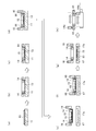
- FIG. 1A to 1I schematically show the resin placing step, the transporting step, and the steps before and after that in the present embodiment.
- a release film (release film) 12 is pasted on an XY table 11.
- the XY table 11 may be, for example, a suction table that can suck the release film 12.
- a cavity is provided inside the XY table 11, a groove or a pore connected to the cavity is provided on the release film adsorption surface, and the inside of the XY table 11 is depressurized to release the groove or the pore.
- the film 12 may be adsorbed.
- the release film 12 may be formed by, for example, attaching a part of a long release film to the XY table 11 and then cutting the release film to leave only a part necessary for the subsequent process. good.
- a heat radiating plate (heat sink) 13 is placed at the center of the release film 12.
- the radiator plate 13 corresponds to the “plate member” in the manufacturing method of the present invention.
- the tray cover 14 is placed on the pasted release film 12, and the release film 12 is sandwiched between the XY table 11 and the tray cover 14. As illustrated, the tray cover 14 covers the peripheral portion of the heat radiating plate 13 and the release film 12 on the outer side, and does not cover the central portion of the heat radiating plate 13.
- the resin 15 is placed on the portion of the heat radiating plate 13 that is not covered with the tray cover 14. As a result, the resin 15 is surrounded by the tray cover 14 as illustrated.
- the process of FIG. 1D corresponds to the “resin placing process” in the manufacturing method of the present invention.
- the release film 12 is held by the resin handler 16 together with the heat radiating plate 13, the resin 15 and the tray cover 14 placed thereon.
- the resin handler 16 has a portion that holds the tray cover 14 and the heat radiating plate 13 sandwiched from the lateral direction, and a portion that holds the peripheral portion of the release film 12 from above and below.
- the resin handler 16 corresponds to the “conveying means” in the manufacturing apparatus of the present invention.
- the heat sink 13 and the resin 15 are placed on the release film 12 and the tray cover 14, and the resin handler 16 causes the lower mold 17 to move onto the lower mold cavity 17 a. Move to. Further, as shown in FIG.
- the release film 12, the heat radiating plate 13, the resin 15, and the tray cover 14 are released from being held by the resin handler 16 and transferred to the lower mold 17.
- the resin 15 is placed on the cavity surface (the position of the mold cavity) of the lower mold cavity 17a while being placed on the heat radiating plate 13. That is, the steps shown in FIGS. 1E to 1H correspond to the “conveying step” in the manufacturing method of the present invention.
- the “resin sealing step” is performed using the lower mold 17 after FIG. This will be described separately with reference to FIGS.
- FIG. 1H only the tray cover 14 is conveyed to the cleaning stage by the resin handler 16.
- a new release film, heat radiating plate, and resin are used. Step (h) is repeated.
- the molding die for compression molding (for example, a compression molding die) is not particularly limited, but may be formed from, for example, an upper die and a lower die.
- the mold in the present embodiment is formed of a lower mold 17 and an upper mold 20 as shown in FIGS.
- the “mold cavity” may be formed only in the lower mold, may be formed only in the upper mold, or the cavity is formed in each of the lower mold and the upper mold.
- a combination of the lower mold cavity and the upper mold cavity may be the “mold cavity”.
- the “conveying step” is a step of conveying the resin to the position of the mold cavity of the molding die while being placed on the plate-like member as described above.
- the “convey to the position of the mold cavity of the mold” may be placed on the mold cavity surface of the lower mold, for example, as shown in FIG. May be placed on the position of the lower mold corresponding to the upper mold cavity.
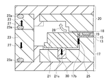
- FIGS. 2 to 6 the manufacturing method of this example will be described in more detail, including the “resin sealing process”, and the manufacturing apparatus used therefor will also be described.
- . 2 to 6 the same components as those in FIG. 1 are denoted by the same reference numerals. However, for convenience of illustration, the shape and the like may be different from those in FIG.
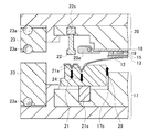
- a part of a manufacturing apparatus in the present embodiment is schematically shown in the sectional view of FIG.
- This manufacturing apparatus includes a resin placing unit, a mold having a mold cavity, a conveying unit, and a resin sealing unit as main components.
- the resin placing means is means for placing the resin 15 on the heat radiating plate 13 in FIG.
- the molding die is formed of a lower die 17 and an upper die 20, and has a lower die cavity (die cavity) 17a.
- the transport means is the resin handler 16 shown in FIG.
- the resin sealing means is a component of the manufacturing apparatus and includes all the components shown in FIG. 2, and also includes the mold (lower mold 17 and upper mold 20). That is, the resin sealing means includes a lower mold 17, an upper mold 20, a clamper 20a, a film retainer 22, and an FM (fine mold) cover 23 as main components as shown in the figure.
- the lower die 17 includes a lower die chase holder that is an outer (lower) member, a lower die chase attached to the inner side (upper side) of the lower die chase holder, and a lower die outer periphery presser 21. including.
- the lower die outer periphery presser 21 is attached to the lower die chase by a spring 21 s and also serves as a peripheral portion of the lower die 17.
- the upper die 20 includes an upper die chase holder that is an outer (upper) member, and an upper die chase attached to the inner side (lower side) of the upper die chase holder.
- the clamper 20a is attached to the upper chase, and as shown in the figure, the substrate 18 for resin-encapsulated electronic components can be fixed to the mold surface (lower surface) of the upper chase.
- the film presser 22 is attached to the peripheral portion of the upper chase by a spring 22s and can be fixed with the release film 12 from above and below together with the lower mold outer periphery front presser 21.
- FM covers (outside air blocking members) 23 are respectively attached to the peripheral portions of the upper die chase holder and the lower die chase holder (outside the upper die chase and the lower die chase). Also, between the upper chase holder and the upper FM cover 23, between the upper FM cover 23 and the lower FM cover 23, and between the lower FM cover 23 and the lower chase holder. Each is provided with an elastic O-ring 23a.
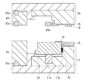
- the resin sealing means is in a state where the electronic component 19 is immersed in the resin 15 placed on the heat sink (plate member) 13 in the lower mold cavity (mold cavity) 17a.
- This is means for resin-sealing the electronic component 19 by compression molding the resin 15 together with the plate-like member 13 and the electronic component 19.
- the release film 12, the heat dissipation plate 13, the resin 15, the substrate 18, and the electronic component 19 are not constituent elements of the manufacturing apparatus.
- FIGS. 1A to 1H a resin placing process for placing the resin 15 on the heat sink 13 and the resin 15 placed in the state where the resin 15 is placed on the heat sink 13 A transporting process for transporting to the position of the mold cavity 17a is performed.
- FIGS. 1F to 1H the steps shown in FIGS. 1F to 1H will be described in more detail with reference to FIGS. That is, FIG. 2 shows the process of FIG. 1 (f), FIG. 3 shows the process of FIG. 1 (g), and FIG. 4 shows the process of FIG. 1 (h) in more detail. .
- the tray cover 14 and the resin handler 16 are omitted for convenience of illustration.
- the heat radiating plate 13 and the resin 15 are moved onto the lower mold cavity 17 a while being placed on the release film 12.
- a substrate 18 for resin-encapsulated electronic components is fixed to the lower surface (mold surface) of the upper mold 20 of the upper mold 20 by a clamper 20a, as shown.
- An electronic component 19 is attached to the lower surface of the substrate 18 so as to face the resin 15.
- the substrate 18 is separately conveyed and fixed to the lower surface (mold surface) of the upper chase.
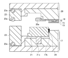
- the release film 12, the heat dissipation plate 13 and the resin 15 are transferred to the lower mold 17, and as indicated by an arrow 24, the inside of the lower mold outer periphery presser 21 is vacuum pumped (see FIG. 3). (Not shown), and the release film 12 is adsorbed in the release film adsorption groove 21a. As a result, tension is applied to the release film 12 disposed on the lower mold cavity 17a.
- the space 17b between the lower die outer periphery presser 21 and the lower die chase is decompressed by a vacuum pump (not shown), and the release film 12 is moved to the lower die cavity. Adsorption onto the cavity surface of 17a. As a result, the resin 15 is placed on the cavity surface of the lower mold cavity 17a (the position of the mold cavity) in a state of being placed on the heat radiating plate 13, as shown in the figure.
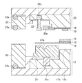
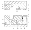
- FIGS. 5 to 6 the resin sealing step is performed.
- the clamper 20a is not shown for convenience.
- the lower mold 17 is raised together with the FM cover 23, and the release film 12 is held between the lower mold outer periphery presser 21 and the film presser 22.
- a force that pushes the spring 22 of the film presser 22 upward works, and the reaction acts as a force that fixes the release film 12.
- a force to push downward acts on the spring 21s of the lower die outer periphery presser 21 and the reaction acts as a force for fixing the release film 12.
- the lower mold 17 is further raised to the compression molding start position, and the electronic component 19 is immersed in the resin 15 in the lower mold cavity 17a. At this time, the resin 15 is in a fluid state.
- the inside of the chase holder (at least in the lower mold cavity 17a) is depressurized by a vacuum pump and an FM suction valve (not shown).
- the resin 15 is compression-molded together with the heat radiating plate 13, the electronic component 19, and the substrate 18, and the electronic component 19 is resin-sealed.
- the “resin sealing step” can be performed to manufacture a resin-sealed electronic component formed of the substrate 18, the electronic component 19, and the resin 15.
- the fluid resin 15 may be, for example, a liquid resin (such as a thermosetting resin before curing), or a solid resin such as a granule, a powder, or a paste is heated. The melted state may be used.
- the resin 15 can be heated by, for example, heating the lower mold 17 or the like.
- the resin 15 in the lower mold cavity 17a may be pressurized and thermoset.
- the electronic component 19 can be resin-sealed (compressed) in a resin molded body (package) corresponding to the shape of the lower mold cavity 17a. If it does in this way, it is also possible to form in the state which exposed the plate-shaped member 13 on the upper surface (surface on the opposite side to a board
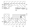
- the lower mold 17 After compression molding (resin sealing), as shown in FIG. 6, the lower mold 17 is lowered and the inside of the chase holder is opened to release the reduced pressure. Thereby, as indicated by an arrow 29, the pressure reduction of the gap 17b between the lower die outer periphery presser 21 and the lower die chase is also released.
- the release film 12 continues to be attracted to the release film suction groove 21a on the upper surface of the lower mold outer periphery front presser 21, and the substrate 18 is fixed to the lower surface (mold surface) of the upper mold chase by the clamper 20a. It continues to be.
- the resin 15 and the heat radiating plate 13 are compression-molded together with the substrate 18 and the electronic component 19, the resin mold and the electronic component 19 formed from the substrate 18, the electronic component 19, and the resin 15 are lowered by lowering the lower mold 17.
- the release film 12 is peeled off.
- the resin-encapsulated electronic component can be transported out of the apparatus of FIG. 2 by another transport means (not shown).
- FM (fine mold) molding is used in which the inside of the chase holder (at least inside the mold cavity) is subjected to compression molding under reduced pressure.
- compression molding compression molding
- 13 may be a plate-like member other than the heat radiating plate, for example, a shielding plate (shield plate).
- the manufacturing method of the present invention is a process including the resin placing process, the transporting process, and the resin sealing process.
- the other These optional steps may be included.
- the plate-like member on which the resin is placed is placed on the release film, and in this state, the resin is transported into the mold cavity of the mold.
- the resin 15 is transported into the mold cavity of the mold.
- FIGS. 2 to 6 it is possible to prevent the resin 15 from contacting the lower mold 17 and the resin 15 from entering the gap 17 b of the lower mold 17.
- the structure of the plate-like member and its conveying means can be easily simplified.
- the heat radiating plate 13 has a resin housing portion. More specifically, as shown in the figure, the heat radiating plate 13 of the present embodiment has a tray shape with the peripheral portion raised vertically, and the central portion of the heat radiating plate 13 is a resin housing portion.
- the resin placing step the resin 15 is placed in the resin housing portion, and the transporting step and the compression molding step are performed in a state where the resin 15 is placed in the resin housing portion.
- the release film 12 is not used.
- the resin handler 16 has a portion for holding the tray cover 14 and the heat radiating plate 13 from the lateral direction, and does not have a portion for holding the release film 12.
- FIGS. 7A to 7H are the same as FIGS. 1B to 1I except that the release film 12 is not used, the shape of the heat sink 13 is different, and the structure of the resin handler 16 described above. Is the same.
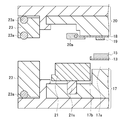
- the manufacturing method and the manufacturing apparatus shown in the schematic process cross-sectional views of FIGS. 8 to 11 do not use the release film 12, do not have the release film suction groove 21a, the film presser 22 and the spring 22s, and the heat sink. Except that the shape of 13 is different, it is the same as FIGS. 2 and 4 to 6 of the first embodiment. Since the release film 12 is not used, the step of FIG. 3 for adsorbing the release film to the release film adsorption groove 21a is omitted. A downward arrow 30 in FIG. 10 indicates a direction in which a force is applied to the spring 21s.
- the peripheral portion of the heat sink 13 is raised and the central portion is a resin accommodating portion, the contact between the resin 15 and the lower die 17 and the resin can be achieved without using the release film 12. It is possible to suppress or prevent 15 from entering the gap 17b between the lower mold outer periphery front presser 21 and the lower mold chase. For this reason, since the cost reduction by omission of a release film and the process of sticking or adsorbing the release film can be omitted, the manufacturing efficiency of the resin-encapsulated electronic component is improved.
- the shape and structure of the plate-like member such as a heat sink are not limited to those shown in FIGS. 7 to 11, and various shapes and structures are possible. Examples thereof are shown in FIGS. These are all examples of a production method and a production apparatus that do not use a release film.
- FIG. 12 shows an example in which the shape of the heat dissipation plate 13 is a flat plate shape.
- type outer periphery tip retainer 21 has a level
- FIG. 13 is an example in which the peripheral portion of the heat radiating plate 13 is raised and the central portion is a resin accommodating portion, as in FIGS.
- FIG. 14 shows an example in which the shape of the heat dissipation plate 13 is a flat plate shape.
- the structure of the manufacturing apparatus is the same as in FIGS.
- the heat sink 13 is press-molded with the lower mold 17, the upper mold 20, and the lower mold outer periphery presser 21 at the time of compression molding, as shown by an arrow 31, so that the heat sink 13 of FIGS.
- it can be made into a tray shape in which the peripheral portion is raised and the central portion is a resin accommodating portion.
- FIGS. 8 to 11 the contact between the resin 15 and the lower mold 17 and the entry of the resin 15 into the gap 17b between the lower mold outer periphery front presser 21 and the lower mold chase are suppressed or prevented. it can.
- FIG. 15 is an example in which the raised portion (outer wall) of the peripheral portion of the heat radiating plate 13 is formed of a material different from that of the heat radiating plate main body (flat plate portion).
- the heat sink main body may be made of metal
- the raised portion (outer wall) of the peripheral edge may be made of a heat resistant resin. The rest is the same as in FIGS.
- FIG. 16 shows an example in which the upper part of the raised portion at the peripheral edge of the heat sink 13 protrudes horizontally toward the outside of the heat sink 13 and the protrusion can be placed on the lower die outer periphery presser 21. It is. Thereby, the contact between the resin 15 and the lower mold 17 and the penetration of the resin 15 into the gap 17b between the lower mold outer periphery presser 21 and the lower mold chase can be further effectively suppressed or prevented. The rest is the same as in FIGS.
- 13 may be a plate-like member other than the heat radiating plate as in the first embodiment, and may be a shielding plate (shield plate), for example.
- the resin-encapsulated electronic component manufactured in the present invention may have one or more electronic components, for example.
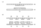
- An example of a member for manufacturing a resin-encapsulated electronic component in which the number of electronic components is 1 is schematically shown in the sectional view of FIG.
- the manufacturing member includes a substrate 18 and a plate-like member (for example, a heat radiating plate, a shield plate) 13.
- An electronic component 19 is fixed to the mold surface of the substrate 18, and a resin 15 is placed on one surface of the plate-like member 13.
- the electronic component 19 and the resin 15 are opposed to each other, and the electronic component 19 is sealed with the resin 15 as shown in Example 1 or 2, for example, to manufacture a resin-encapsulated electronic component.
- FIG. 17B schematically shows an example of a member for manufacturing a resin-encapsulated electronic component having a plurality of electronic components.
- a plurality of electronic components 19 are fixed on the substrate 18, the number of plate-like members 13 and the resin 15 is the same as the number of electronic components 19, and the plate-like members 13 are placed on the release film 12. Except this, it is the same as FIG.
- the release film 12 may be omitted, but when there are a plurality of plate-like members 13 and resins 15, it is convenient and preferable to place and handle them on the release film 12 as shown in FIG. .
- a resin-encapsulated electronic component can be manufactured in the same manner as in Example 1 using the release film 12.
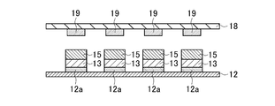
- the plate-like member may be fixed on the release film with an adhesive.
- An example is schematically shown in the sectional view of FIG. FIG. 18 shows that a plurality of micro regions (slight adhesive) of the adhesive 12a are provided on the release film 12, and the plate-like member 13 is fixed on the release film 12 by the micro adhesive 12a. Except for this, it is the same as FIG. In this way, the plate member is fixed on the release film with an adhesive, and may be used for manufacturing a resin-encapsulated electronic component having one electronic component. For example, as shown in FIG. It is preferable to use the resin-encapsulated electronic component having a plurality of electronic components. Thereby, the resin 15 can be prevented from entering between the plate-like member 13 and the release film 12.
Abstract
Description
電子部品を樹脂封止した樹脂封止電子部品の製造方法であって、
前記樹脂封止電子部品が、板状部材を有する樹脂封止電子部品であり、
前記製造方法は、
前記板状部材上に前記樹脂を載置する樹脂載置工程と、
前記樹脂を、前記板状部材上に載置された状態で、成形型の型キャビティの位置まで搬送する搬送工程と、
前記型キャビティ内において、前記板状部材上に載置された前記樹脂に前記電子部品を浸漬させた状態で、前記樹脂を前記板状部材及び前記電子部品とともに圧縮成形することにより、前記電子部品を樹脂封止する樹脂封止工程とを含むことを特徴とする。
電子部品を樹脂封止した樹脂封止電子部品の製造装置であって、
前記樹脂封止電子部品が、板状部材を有する樹脂封止電子部品であり、
前記製造装置は、
樹脂載置手段と、型キャビティを有する成形型と、搬送手段と、樹脂封止手段とを有し、
前記樹脂載置手段は、前記板状部材上に前記樹脂を載置し、
前記搬送手段は、前記樹脂を、前記板状部材上に載置された状態で、前記型キャビティの位置まで搬送し、
前記樹脂封止手段は、前記型キャビティ内において、前記板状部材上に載置された前記樹脂に前記電子部品を浸漬させた状態で、前記樹脂を前記板状部材及び前記電子部品とともに圧縮成形することにより、前記電子部品を樹脂封止することを特徴とする。
12 離型フィルム
13 放熱板(板状部材)
14 トレーカバー
14c クリーナ
15 樹脂
16 レジンハンドラー
17 下型
17a 下型キャビティ(型キャビティ)
17b 空隙
18 基板
19 電子部品
20 上型
21 下型外周先押え
22 フィルム押え
21s、22s スプリング
23 FMカバー
23a Oリング
24、25 減圧による吸着
26、30 スプリングに加えられる力の向き
27 FMカバーに加えられる力の向き
28 チェイスホルダ内の減圧
29 減圧の解除
31 放熱板13の移動方向
Claims (11)
- 電子部品を樹脂封止した樹脂封止電子部品の製造方法であって、
前記樹脂封止電子部品が、板状部材を有する樹脂封止電子部品であり、
前記製造方法は、
前記板状部材上に前記樹脂を載置する樹脂載置工程と、
前記樹脂を、前記板状部材上に載置された状態で、成形型の型キャビティの位置まで搬送する搬送工程と、
前記型キャビティ内において、前記板状部材上に載置された前記樹脂に前記電子部品を浸漬させた状態で、前記樹脂を前記板状部材及び前記電子部品とともに圧縮成形することにより、前記電子部品を樹脂封止する樹脂封止工程とを含むことを特徴とする製造方法。 - 前記板状部材が、放熱板又はシールド板である請求項1記載の製造方法。
- 前記搬送工程において、前記樹脂を載置した前記板状部材が離型フィルム上に載置された状態で、前記樹脂を前記成形型の型キャビティ内に搬送する請求項1又は2記載の製造方法。
- 前記板状部材が、粘着剤により前記離型フィルム上に固定されている請求項3記載の製造方法。
- 前記板状部材が、樹脂収容部を有し、
前記樹脂載置工程において、前記樹脂収容部内に前記樹脂を載置し、
前記搬送工程及び前記圧縮成形工程を、前記樹脂収容部内に前記樹脂が載置された状態で行う請求項1から4のいずれか一項に記載の製造方法。 - 前記樹脂が、熱可塑性樹脂又は熱硬化性樹脂である請求項1から5のいずれか一項に記載の製造方法。
- 前記樹脂が、顆粒状樹脂、粉末状樹脂、液状樹脂、板状樹脂、シート状樹脂、フィルム状樹脂及びペースト状樹脂からなる群から選択される少なくとも一つである請求項1から6のいずれか一項に記載の製造方法。
- 前記樹脂が、透明樹脂、半透明樹脂、及び不透明樹脂からなる群から選択される少なくとも一つである請求項1から7のいずれか一項に記載の製造方法。
- 電子部品を樹脂封止した樹脂封止電子部品の製造装置であって、
前記樹脂封止電子部品が、板状部材を有する樹脂封止電子部品であり、
前記製造装置は、
樹脂載置手段と、型キャビティを有する成形型と、搬送手段と、樹脂封止手段とを有し、
前記樹脂載置手段は、前記板状部材上に前記樹脂を載置し、
前記搬送手段は、前記樹脂を、前記板状部材上に載置された状態で、前記型キャビティの位置まで搬送し、
前記樹脂封止手段は、前記型キャビティ内において、前記板状部材上に載置された前記樹脂に前記電子部品を浸漬させた状態で、前記樹脂を前記板状部材及び前記電子部品とともに圧縮成形することにより、前記電子部品を樹脂封止することを特徴とする製造装置。 - 前記搬送手段は、前記樹脂を載置した前記板状部材が離型フィルム上に載置された状態で、前記樹脂を前記成形型の型キャビティ内に搬送する請求項9記載の製造装置。
- 前記樹脂封止手段が、離型フィルム吸着手段を有し、かつ、前記離型フィルムを前記離型フィルム吸着手段に吸着させた状態で前記圧縮成形を行う請求項10記載の製造装置。
Priority Applications (4)
| Application Number | Priority Date | Filing Date | Title |
|---|---|---|---|
| KR1020167002419A KR101897880B1 (ko) | 2012-03-07 | 2012-11-08 | 수지 밀봉 전자 부품의 제조 방법 및 수지 밀봉 전자 부품의 제조 장치 |
| KR1020137034312A KR101591065B1 (ko) | 2012-03-07 | 2012-11-08 | 수지 밀봉 전자 부품의 제조 방법 및 수지 밀봉 전자 부품의 제조 장치 |
| US14/381,887 US20150017372A1 (en) | 2012-03-07 | 2012-11-08 | Method of manufacturing resin-encapsulated electronic component and apparatus for manufacturing resin-encapsulated electronic component |
| CN201280030884.4A CN103620752B (zh) | 2012-03-07 | 2012-11-08 | 树脂封装电子元件的制造方法及树脂封装电子元件的制造装置 |
Applications Claiming Priority (2)
| Application Number | Priority Date | Filing Date | Title |
|---|---|---|---|
| JP2012051057A JP6039198B2 (ja) | 2012-03-07 | 2012-03-07 | 樹脂封止電子部品の製造方法及び樹脂封止電子部品の製造装置 |
| JP2012-051057 | 2012-03-07 |
Publications (1)
| Publication Number | Publication Date |
|---|---|
| WO2013132693A1 true WO2013132693A1 (ja) | 2013-09-12 |
Family
ID=49116195
Family Applications (1)
| Application Number | Title | Priority Date | Filing Date |
|---|---|---|---|
| PCT/JP2012/078996 WO2013132693A1 (ja) | 2012-03-07 | 2012-11-08 | 樹脂封止電子部品の製造方法及び樹脂封止電子部品の製造装置 |
Country Status (6)
| Country | Link |
|---|---|
| US (1) | US20150017372A1 (ja) |
| JP (1) | JP6039198B2 (ja) |
| KR (2) | KR101591065B1 (ja) |
| CN (3) | CN108346589A (ja) |
| TW (2) | TWI529820B (ja) |
| WO (1) | WO2013132693A1 (ja) |
Families Citing this family (27)
| Publication number | Priority date | Publication date | Assignee | Title |
|---|---|---|---|---|
| JP6057880B2 (ja) * | 2013-11-28 | 2017-01-11 | Towa株式会社 | 圧縮成形装置の樹脂材料供給方法及び供給装置 |
| JP6049597B2 (ja) * | 2013-11-28 | 2016-12-21 | Towa株式会社 | 圧縮成形装置の樹脂材料供給方法及び供給機構、並びに圧縮成形方法及び圧縮成形装置 |
| JP6117715B2 (ja) * | 2014-02-18 | 2017-04-19 | 信越化学工業株式会社 | 真空ラミネーション装置および半導体装置の製造方法 |
| JP6017492B2 (ja) * | 2014-04-24 | 2016-11-02 | Towa株式会社 | 樹脂封止電子部品の製造方法、突起電極付き板状部材、及び樹脂封止電子部品 |
| JP6430143B2 (ja) * | 2014-04-30 | 2018-11-28 | Towa株式会社 | 樹脂成形装置及び樹脂成形方法並びに成形製品の製造方法 |
| JP6310773B2 (ja) * | 2014-05-22 | 2018-04-11 | Towa株式会社 | 樹脂成形装置及び樹脂成形方法 |
| JP6298719B2 (ja) * | 2014-06-09 | 2018-03-20 | Towa株式会社 | 樹脂封止装置及び樹脂封止方法 |
| JP5944445B2 (ja) * | 2014-07-18 | 2016-07-05 | Towa株式会社 | 樹脂封止電子部品の製造方法、突起電極付き板状部材、樹脂封止電子部品、及び突起電極付き板状部材の製造方法 |
| KR101640773B1 (ko) * | 2014-09-15 | 2016-07-19 | (주) 에스에스피 | 전자파 차폐막을 구비한 반도체 패키지의 제조 방법 및 이를 위한 장치 |
| JP6400446B2 (ja) * | 2014-11-28 | 2018-10-03 | Towa株式会社 | 突起電極付き板状部材の製造方法、突起電極付き板状部材、電子部品の製造方法、及び電子部品 |
| JP6237732B2 (ja) * | 2015-08-28 | 2017-11-29 | 東洋インキScホールディングス株式会社 | 電子部品モジュールの製造方法 |
| JP6654861B2 (ja) * | 2015-11-09 | 2020-02-26 | Towa株式会社 | 樹脂封止装置及び樹脂封止方法 |
| JP6598642B2 (ja) * | 2015-11-09 | 2019-10-30 | Towa株式会社 | 樹脂封止装置及び樹脂封止方法 |
| US9953929B2 (en) * | 2016-03-18 | 2018-04-24 | Intel Corporation | Systems and methods for electromagnetic interference shielding |
| JP6640003B2 (ja) * | 2016-04-05 | 2020-02-05 | Towa株式会社 | 樹脂封止装置及び樹脂封止方法 |
| JP6218891B1 (ja) * | 2016-06-24 | 2017-10-25 | Towa株式会社 | 樹脂成形装置、樹脂成形品の製造方法及び製品の製造方法 |
| JP6827283B2 (ja) * | 2016-08-03 | 2021-02-10 | Towa株式会社 | 成形型、樹脂成形装置及び樹脂成形品の製造方法 |
| CN106672619A (zh) * | 2017-02-15 | 2017-05-17 | 苏州迈瑞微电子有限公司 | 塑封料转运设备及方法 |
| CN107167020B (zh) * | 2017-06-05 | 2023-08-11 | 深圳市鸿富诚新材料股份有限公司 | 一体式散热片的制造模具及制造方法 |
| US10199299B1 (en) * | 2017-08-07 | 2019-02-05 | Micron Technology, Inc. | Semiconductor mold compound transfer system and associated methods |
| JP6923394B2 (ja) * | 2017-08-30 | 2021-08-18 | Towa株式会社 | 吸着ハンド、搬送機構、樹脂成形装置、搬送方法および樹脂成形品の製造方法 |
| KR102006757B1 (ko) * | 2017-12-29 | 2019-08-02 | (주)인천측기 | 길이 측정 장치 및 시스템 |
| JP6994445B2 (ja) * | 2018-08-31 | 2022-01-14 | Towa株式会社 | 樹脂成形装置、離型フィルムの剥離方法、樹脂成形品の製造方法 |
| JP6819721B2 (ja) * | 2019-04-26 | 2021-01-27 | 昭和電工マテリアルズ株式会社 | 半導体コンプレッション成型用離型シート及びこれを用いて成型される半導体パッケージ |
| US11548273B2 (en) * | 2020-01-31 | 2023-01-10 | Asmpt Singapore Pte. Ltd. | Apparatus and method for removing a film from a surface |
| CN111446352B (zh) * | 2020-03-23 | 2022-03-18 | 东莞市中麒光电技术有限公司 | Led显示屏模组的制作方法 |
| JP7428384B2 (ja) * | 2020-10-06 | 2024-02-06 | アピックヤマダ株式会社 | 樹脂封止装置及び樹脂封止方法 |
Citations (3)
| Publication number | Priority date | Publication date | Assignee | Title |
|---|---|---|---|---|
| JPH1079362A (ja) * | 1996-07-12 | 1998-03-24 | Fujitsu Ltd | 半導体装置の製造方法及び半導体装置製造用金型及び半導体装置及びその実装方法 |
| JP2011054806A (ja) * | 2009-09-02 | 2011-03-17 | Renesas Electronics Corp | 半導体装置およびその製造方法 |
| JP2011187877A (ja) * | 2010-03-11 | 2011-09-22 | Panasonic Corp | 半導体装置及びその製造方法 |
Family Cites Families (25)
| Publication number | Priority date | Publication date | Assignee | Title |
|---|---|---|---|---|
| US4135017A (en) * | 1977-12-12 | 1979-01-16 | Hoffmann Sr Dennis | Laminate patch |
| US4728380A (en) * | 1984-11-15 | 1988-03-01 | The Excello Specialty Company | Transfer method of applying adhesive to substrates |
| JPS6235813A (ja) * | 1985-08-09 | 1987-02-16 | Hitachi Ltd | 成形装置 |
| JP3190702B2 (ja) * | 1990-10-08 | 2001-07-23 | 株式会社東芝 | 半導体装置の製造方法 |
| JP2665172B2 (ja) * | 1994-11-15 | 1997-10-22 | ローム株式会社 | 半導体装置の製造方法 |
| KR100418743B1 (ko) * | 1996-07-12 | 2004-02-18 | 후지쯔 가부시끼가이샤 | 반도체 장치의 제조 방법 및 반도체 장치 |
| KR100533067B1 (ko) * | 1999-12-16 | 2005-12-02 | 다이-이치 세이코 가부시키가이샤 | 수지봉지용 금형장치 |
| US6596361B2 (en) * | 2001-03-07 | 2003-07-22 | Ccl Label, Inc. | Lenticular label manufacture |
| JP2003077944A (ja) * | 2001-06-22 | 2003-03-14 | Nitto Denko Corp | 接着フィルム付き半導体ウェハの製造方法 |
| JP4081397B2 (ja) * | 2002-07-31 | 2008-04-23 | 第一精工株式会社 | フィルム貼着装置およびフィルム貼着方法 |
| JP2005219297A (ja) * | 2004-02-04 | 2005-08-18 | Apic Yamada Corp | 樹脂モールド方法および樹脂モールド装置 |
| JP2006294832A (ja) * | 2005-04-11 | 2006-10-26 | Renesas Technology Corp | 半導体装置の製造方法 |
| JP2007251094A (ja) * | 2006-03-20 | 2007-09-27 | Towa Corp | 半導体チップの樹脂封止成形装置 |
| MY154681A (en) * | 2007-03-13 | 2015-07-15 | Towa Corp | Method of compression molding for electronic part and apparatus therefor |
| JP4855329B2 (ja) * | 2007-05-08 | 2012-01-18 | Towa株式会社 | 電子部品の圧縮成形方法及び装置 |
| JP2009140962A (ja) * | 2007-12-03 | 2009-06-25 | Panasonic Corp | 半導体装置およびその製造方法 |
| JP5128363B2 (ja) * | 2008-05-02 | 2013-01-23 | Towa株式会社 | 半導体チップの樹脂封止成形方法及び金型 |
| JP5280102B2 (ja) * | 2008-05-26 | 2013-09-04 | ルネサスエレクトロニクス株式会社 | 半導体装置の製造方法 |
| JP2010114256A (ja) * | 2008-11-06 | 2010-05-20 | Panasonic Corp | 半導体装置、および半導体装置の製造方法 |
| JP2010129632A (ja) * | 2008-11-26 | 2010-06-10 | Toppan Printing Co Ltd | 剥離シート付き接着シートおよび金属板貼合装置および金属板貼合方法 |
| JP2010247429A (ja) * | 2009-04-15 | 2010-11-04 | Apic Yamada Corp | 樹脂封止装置とこれを用いた樹脂封止方法 |
| JP2011228540A (ja) * | 2010-04-21 | 2011-11-10 | Panasonic Corp | 半導体装置およびその製造方法 |
| US8012799B1 (en) * | 2010-06-08 | 2011-09-06 | Freescale Semiconductor, Inc. | Method of assembling semiconductor device with heat spreader |
| JP5576197B2 (ja) * | 2010-07-08 | 2014-08-20 | Towa株式会社 | 電子部品の圧縮成形方法及び成形装置 |
| TWI431697B (zh) * | 2010-11-08 | 2014-03-21 | Advanced Semiconductor Eng | 半導體封裝件之製造方法及製造其之封裝模具 |
-
2012
- 2012-03-07 JP JP2012051057A patent/JP6039198B2/ja active Active
- 2012-11-08 CN CN201810146769.2A patent/CN108346589A/zh active Pending
- 2012-11-08 KR KR1020137034312A patent/KR101591065B1/ko active IP Right Grant
- 2012-11-08 WO PCT/JP2012/078996 patent/WO2013132693A1/ja active Application Filing
- 2012-11-08 CN CN201810146770.5A patent/CN108346590A/zh active Pending
- 2012-11-08 CN CN201280030884.4A patent/CN103620752B/zh active Active
- 2012-11-08 US US14/381,887 patent/US20150017372A1/en not_active Abandoned
- 2012-11-08 KR KR1020167002419A patent/KR101897880B1/ko active IP Right Grant
-
2013
- 2013-01-16 TW TW102101680A patent/TWI529820B/zh active
- 2013-01-16 TW TW105100968A patent/TWI613739B/zh active
Patent Citations (3)
| Publication number | Priority date | Publication date | Assignee | Title |
|---|---|---|---|---|
| JPH1079362A (ja) * | 1996-07-12 | 1998-03-24 | Fujitsu Ltd | 半導体装置の製造方法及び半導体装置製造用金型及び半導体装置及びその実装方法 |
| JP2011054806A (ja) * | 2009-09-02 | 2011-03-17 | Renesas Electronics Corp | 半導体装置およびその製造方法 |
| JP2011187877A (ja) * | 2010-03-11 | 2011-09-22 | Panasonic Corp | 半導体装置及びその製造方法 |
Also Published As
| Publication number | Publication date |
|---|---|
| KR20160015407A (ko) | 2016-02-12 |
| JP2013187340A (ja) | 2013-09-19 |
| TW201643972A (zh) | 2016-12-16 |
| TW201338063A (zh) | 2013-09-16 |
| KR20140016395A (ko) | 2014-02-07 |
| TWI529820B (zh) | 2016-04-11 |
| CN103620752A (zh) | 2014-03-05 |
| TWI613739B (zh) | 2018-02-01 |
| JP6039198B2 (ja) | 2016-12-07 |
| KR101897880B1 (ko) | 2018-09-12 |
| US20150017372A1 (en) | 2015-01-15 |
| KR101591065B1 (ko) | 2016-02-02 |
| CN103620752B (zh) | 2018-03-16 |
| CN108346590A (zh) | 2018-07-31 |
| CN108346589A (zh) | 2018-07-31 |
Similar Documents
| Publication | Publication Date | Title |
|---|---|---|
| JP6039198B2 (ja) | 樹脂封止電子部品の製造方法及び樹脂封止電子部品の製造装置 | |
| JP5944445B2 (ja) | 樹脂封止電子部品の製造方法、突起電極付き板状部材、樹脂封止電子部品、及び突起電極付き板状部材の製造方法 | |
| JP6017492B2 (ja) | 樹脂封止電子部品の製造方法、突起電極付き板状部材、及び樹脂封止電子部品 | |
| TWI679100B (zh) | 樹脂成形裝置及樹脂成形品製造方法 | |
| TWI570862B (zh) | Resin sealing device and resin sealing method | |
| JP6349447B2 (ja) | 樹脂封止電子部品の製造方法及び樹脂封止電子部品の製造装置 | |
| KR101614970B1 (ko) | 수지밀봉완료기판의 냉각장치, 냉각방법 및 반송장치, 그리고 수지밀봉장치 | |
| JP2016022672A (ja) | 成形金型、成形装置および成形品の製造方法 | |
| JP6193951B2 (ja) | 樹脂封止電子部品の製造方法及び樹脂封止電子部品の製造装置 | |
| TW201818482A (zh) | 樹脂封裝裝置及樹脂封裝方法 | |
| JP6400446B2 (ja) | 突起電極付き板状部材の製造方法、突起電極付き板状部材、電子部品の製造方法、及び電子部品 | |
| JP5816399B2 (ja) | 成形型、基板吸着型、樹脂封止装置および樹脂封止電子部品の製造方法 | |
| WO2015087763A1 (ja) | 封止シート貼付け方法 | |
| TWI718447B (zh) | 成型模、樹脂成型裝置及樹脂成型品的製造方法 | |
| JP2016015522A5 (ja) | ||
| JP5143681B2 (ja) | 樹脂封止装置 | |
| CN116313850A (zh) | 晶片转移方法 | |
| TWM330553U (en) | Die pick-and-place machine |
Legal Events
| Date | Code | Title | Description |
|---|---|---|---|
| 121 | Ep: the epo has been informed by wipo that ep was designated in this application |
Ref document number: 12870735 Country of ref document: EP Kind code of ref document: A1 |
|
| ENP | Entry into the national phase |
Ref document number: 20137034312 Country of ref document: KR Kind code of ref document: A |
|
| NENP | Non-entry into the national phase |
Ref country code: DE |
|
| WWE | Wipo information: entry into national phase |
Ref document number: 14381887 Country of ref document: US |
|
| 122 | Ep: pct application non-entry in european phase |
Ref document number: 12870735 Country of ref document: EP Kind code of ref document: A1 |