WO2013129335A1 - 近赤外反射フィルムおよびこれを用いた近赤外反射ガラス - Google Patents
近赤外反射フィルムおよびこれを用いた近赤外反射ガラス Download PDFInfo
- Publication number
- WO2013129335A1 WO2013129335A1 PCT/JP2013/054809 JP2013054809W WO2013129335A1 WO 2013129335 A1 WO2013129335 A1 WO 2013129335A1 JP 2013054809 W JP2013054809 W JP 2013054809W WO 2013129335 A1 WO2013129335 A1 WO 2013129335A1
- Authority
- WO
- WIPO (PCT)
- Prior art keywords
- refractive index
- index layer
- thickness
- dielectric film
- infrared reflective
- Prior art date
Links
- 239000011521 glass Substances 0.000 title claims description 33
- 239000010408 film Substances 0.000 claims abstract description 462
- 239000012788 optical film Substances 0.000 claims abstract description 172
- 229920005989 resin Polymers 0.000 claims description 90
- 239000011347 resin Substances 0.000 claims description 90
- 239000002245 particle Substances 0.000 claims description 42
- 229910044991 metal oxide Inorganic materials 0.000 claims description 26
- 150000004706 metal oxides Chemical class 0.000 claims description 26
- 238000011049 filling Methods 0.000 claims description 4
- 239000010410 layer Substances 0.000 description 507
- 238000000034 method Methods 0.000 description 56
- 230000000052 comparative effect Effects 0.000 description 52
- 238000000576 coating method Methods 0.000 description 49
- -1 polyethylene Polymers 0.000 description 47
- 229920002451 polyvinyl alcohol Polymers 0.000 description 46
- 239000011248 coating agent Substances 0.000 description 42
- 239000004372 Polyvinyl alcohol Substances 0.000 description 40
- 235000019422 polyvinyl alcohol Nutrition 0.000 description 40
- 229920002678 cellulose Polymers 0.000 description 37
- 239000001913 cellulose Substances 0.000 description 32
- 235000010980 cellulose Nutrition 0.000 description 32
- 229920002554 vinyl polymer Polymers 0.000 description 29
- 239000000243 solution Substances 0.000 description 21
- GWEVSGVZZGPLCZ-UHFFFAOYSA-N Titan oxide Chemical compound O=[Ti]=O GWEVSGVZZGPLCZ-UHFFFAOYSA-N 0.000 description 20
- NBBJYMSMWIIQGU-UHFFFAOYSA-N Propionic aldehyde Chemical compound CCC=O NBBJYMSMWIIQGU-UHFFFAOYSA-N 0.000 description 14
- 238000002834 transmittance Methods 0.000 description 14
- ZTQSAGDEMFDKMZ-UHFFFAOYSA-N Butyraldehyde Chemical compound CCCC=O ZTQSAGDEMFDKMZ-UHFFFAOYSA-N 0.000 description 13
- VYPSYNLAJGMNEJ-UHFFFAOYSA-N Silicium dioxide Chemical compound O=[Si]=O VYPSYNLAJGMNEJ-UHFFFAOYSA-N 0.000 description 13
- 239000000758 substrate Substances 0.000 description 13
- OGIDPMRJRNCKJF-UHFFFAOYSA-N titanium oxide Inorganic materials [Ti]=O OGIDPMRJRNCKJF-UHFFFAOYSA-N 0.000 description 12
- 238000011282 treatment Methods 0.000 description 12
- 239000003795 chemical substances by application Substances 0.000 description 11
- 229920000159 gelatin Polymers 0.000 description 11
- 230000014509 gene expression Effects 0.000 description 11
- 230000003287 optical effect Effects 0.000 description 11
- 108010010803 Gelatin Proteins 0.000 description 10
- 239000005357 flat glass Substances 0.000 description 10
- 235000019322 gelatine Nutrition 0.000 description 10
- 235000011852 gelatine desserts Nutrition 0.000 description 10
- 150000004676 glycans Chemical class 0.000 description 10
- 229920000139 polyethylene terephthalate Polymers 0.000 description 10
- 239000005020 polyethylene terephthalate Substances 0.000 description 10
- RTZKZFJDLAIYFH-UHFFFAOYSA-N Diethyl ether Natural products CCOCC RTZKZFJDLAIYFH-UHFFFAOYSA-N 0.000 description 9
- OFOBLEOULBTSOW-UHFFFAOYSA-N Malonic acid Chemical compound OC(=O)CC(O)=O OFOBLEOULBTSOW-UHFFFAOYSA-N 0.000 description 9
- 239000002253 acid Substances 0.000 description 9
- 239000012790 adhesive layer Substances 0.000 description 9
- 239000000463 material Substances 0.000 description 9
- HGBOYTHUEUWSSQ-UHFFFAOYSA-N pentanal Chemical compound CCCCC=O HGBOYTHUEUWSSQ-UHFFFAOYSA-N 0.000 description 9
- XLYOFNOQVPJJNP-UHFFFAOYSA-N water Substances O XLYOFNOQVPJJNP-UHFFFAOYSA-N 0.000 description 9
- HRPVXLWXLXDGHG-UHFFFAOYSA-N Acrylamide Chemical compound NC(=O)C=C HRPVXLWXLXDGHG-UHFFFAOYSA-N 0.000 description 8
- NIXOWILDQLNWCW-UHFFFAOYSA-M Acrylate Chemical compound [O-]C(=O)C=C NIXOWILDQLNWCW-UHFFFAOYSA-M 0.000 description 8
- 239000000654 additive Substances 0.000 description 8
- 239000012461 cellulose resin Substances 0.000 description 8
- 239000008119 colloidal silica Substances 0.000 description 8
- 239000003989 dielectric material Substances 0.000 description 8
- 239000008273 gelatin Substances 0.000 description 8
- 239000011112 polyethylene naphthalate Substances 0.000 description 8
- 239000002904 solvent Substances 0.000 description 8
- 238000004544 sputter deposition Methods 0.000 description 8
- 229920000178 Acrylic resin Polymers 0.000 description 7
- 239000004925 Acrylic resin Substances 0.000 description 7
- LFQSCWFLJHTTHZ-UHFFFAOYSA-N Ethanol Chemical compound CCO LFQSCWFLJHTTHZ-UHFFFAOYSA-N 0.000 description 7
- 239000004677 Nylon Substances 0.000 description 7
- 229920013820 alkyl cellulose Polymers 0.000 description 7
- 230000015572 biosynthetic process Effects 0.000 description 7
- 229920002301 cellulose acetate Polymers 0.000 description 7
- MTHSVFCYNBDYFN-UHFFFAOYSA-N diethylene glycol Chemical compound OCCOCCO MTHSVFCYNBDYFN-UHFFFAOYSA-N 0.000 description 7
- 239000000839 emulsion Substances 0.000 description 7
- 238000001125 extrusion Methods 0.000 description 7
- 239000007788 liquid Substances 0.000 description 7
- 229920001778 nylon Polymers 0.000 description 7
- 229920001225 polyester resin Polymers 0.000 description 7
- 239000004645 polyester resin Substances 0.000 description 7
- 229920001282 polysaccharide Polymers 0.000 description 7
- 239000005017 polysaccharide Substances 0.000 description 7
- 150000003839 salts Chemical class 0.000 description 7
- NIXOWILDQLNWCW-UHFFFAOYSA-N 2-Propenoic acid Natural products OC(=O)C=C NIXOWILDQLNWCW-UHFFFAOYSA-N 0.000 description 6
- IKHGUXGNUITLKF-UHFFFAOYSA-N Acetaldehyde Chemical compound CC=O IKHGUXGNUITLKF-UHFFFAOYSA-N 0.000 description 6
- XEKOWRVHYACXOJ-UHFFFAOYSA-N Ethyl acetate Chemical compound CCOC(C)=O XEKOWRVHYACXOJ-UHFFFAOYSA-N 0.000 description 6
- ZZSNKZQZMQGXPY-UHFFFAOYSA-N Ethyl cellulose Chemical compound CCOCC1OC(OC)C(OCC)C(OCC)C1OC1C(O)C(O)C(OC)C(CO)O1 ZZSNKZQZMQGXPY-UHFFFAOYSA-N 0.000 description 6
- OKKJLVBELUTLKV-UHFFFAOYSA-N Methanol Chemical compound OC OKKJLVBELUTLKV-UHFFFAOYSA-N 0.000 description 6
- 239000004698 Polyethylene Substances 0.000 description 6
- 150000001299 aldehydes Chemical class 0.000 description 6
- IISBACLAFKSPIT-UHFFFAOYSA-N bisphenol A Chemical compound C=1C=C(O)C=CC=1C(C)(C)C1=CC=C(O)C=C1 IISBACLAFKSPIT-UHFFFAOYSA-N 0.000 description 6
- 229920003086 cellulose ether Polymers 0.000 description 6
- 150000001875 compounds Chemical class 0.000 description 6
- 150000002148 esters Chemical class 0.000 description 6
- ORUIBWPALBXDOA-UHFFFAOYSA-L magnesium fluoride Chemical compound [F-].[F-].[Mg+2] ORUIBWPALBXDOA-UHFFFAOYSA-L 0.000 description 6
- 229920000573 polyethylene Polymers 0.000 description 6
- 229920000642 polymer Polymers 0.000 description 6
- 239000010409 thin film Substances 0.000 description 6
- 125000004169 (C1-C6) alkyl group Chemical group 0.000 description 5
- 239000001856 Ethyl cellulose Substances 0.000 description 5
- 239000000853 adhesive Substances 0.000 description 5
- 238000001035 drying Methods 0.000 description 5
- 235000019325 ethyl cellulose Nutrition 0.000 description 5
- 229920001249 ethyl cellulose Polymers 0.000 description 5
- 229910052751 metal Inorganic materials 0.000 description 5
- 239000002184 metal Substances 0.000 description 5
- 239000003960 organic solvent Substances 0.000 description 5
- 229920003207 poly(ethylene-2,6-naphthalate) Polymers 0.000 description 5
- 229920002037 poly(vinyl butyral) polymer Polymers 0.000 description 5
- 238000006116 polymerization reaction Methods 0.000 description 5
- 239000000047 product Substances 0.000 description 5
- 239000000126 substance Substances 0.000 description 5
- SMZOUWXMTYCWNB-UHFFFAOYSA-N 2-(2-methoxy-5-methylphenyl)ethanamine Chemical compound COC1=CC=C(C)C=C1CCN SMZOUWXMTYCWNB-UHFFFAOYSA-N 0.000 description 4
- 239000004743 Polypropylene Substances 0.000 description 4
- XUIMIQQOPSSXEZ-UHFFFAOYSA-N Silicon Chemical compound [Si] XUIMIQQOPSSXEZ-UHFFFAOYSA-N 0.000 description 4
- PPBRXRYQALVLMV-UHFFFAOYSA-N Styrene Chemical compound C=CC1=CC=CC=C1 PPBRXRYQALVLMV-UHFFFAOYSA-N 0.000 description 4
- WYURNTSHIVDZCO-UHFFFAOYSA-N Tetrahydrofuran Chemical compound C1CCOC1 WYURNTSHIVDZCO-UHFFFAOYSA-N 0.000 description 4
- RTAQQCXQSZGOHL-UHFFFAOYSA-N Titanium Chemical compound [Ti] RTAQQCXQSZGOHL-UHFFFAOYSA-N 0.000 description 4
- XTXRWKRVRITETP-UHFFFAOYSA-N Vinyl acetate Chemical compound CC(=O)OC=C XTXRWKRVRITETP-UHFFFAOYSA-N 0.000 description 4
- IKHGUXGNUITLKF-XPULMUKRSA-N acetaldehyde Chemical compound [14CH]([14CH3])=O IKHGUXGNUITLKF-XPULMUKRSA-N 0.000 description 4
- 125000002777 acetyl group Chemical group [H]C([H])([H])C(*)=O 0.000 description 4
- 150000001408 amides Chemical class 0.000 description 4
- KGBXLFKZBHKPEV-UHFFFAOYSA-N boric acid Chemical compound OB(O)O KGBXLFKZBHKPEV-UHFFFAOYSA-N 0.000 description 4
- 235000010338 boric acid Nutrition 0.000 description 4
- 229960002645 boric acid Drugs 0.000 description 4
- WERYXYBDKMZEQL-UHFFFAOYSA-N butane-1,4-diol Chemical compound OCCCCO WERYXYBDKMZEQL-UHFFFAOYSA-N 0.000 description 4
- 238000001816 cooling Methods 0.000 description 4
- 239000002270 dispersing agent Substances 0.000 description 4
- 238000010438 heat treatment Methods 0.000 description 4
- FXHGMKSSBGDXIY-UHFFFAOYSA-N heptanal Chemical compound CCCCCCC=O FXHGMKSSBGDXIY-UHFFFAOYSA-N 0.000 description 4
- 229910001635 magnesium fluoride Inorganic materials 0.000 description 4
- 229920001707 polybutylene terephthalate Polymers 0.000 description 4
- 239000004417 polycarbonate Substances 0.000 description 4
- 229920000515 polycarbonate Polymers 0.000 description 4
- 229920005668 polycarbonate resin Polymers 0.000 description 4
- 239000004431 polycarbonate resin Substances 0.000 description 4
- 229920001155 polypropylene Polymers 0.000 description 4
- 229920000036 polyvinylpyrrolidone Polymers 0.000 description 4
- 239000001267 polyvinylpyrrolidone Substances 0.000 description 4
- 235000013855 polyvinylpyrrolidone Nutrition 0.000 description 4
- 230000008569 process Effects 0.000 description 4
- 238000007127 saponification reaction Methods 0.000 description 4
- 239000010703 silicon Substances 0.000 description 4
- 229910052710 silicon Inorganic materials 0.000 description 4
- 229910052814 silicon oxide Inorganic materials 0.000 description 4
- 229920002050 silicone resin Polymers 0.000 description 4
- 229910052719 titanium Inorganic materials 0.000 description 4
- 239000010936 titanium Substances 0.000 description 4
- 125000006528 (C2-C6) alkyl group Chemical group 0.000 description 3
- ZWEHNKRNPOVVGH-UHFFFAOYSA-N 2-Butanone Chemical compound CCC(C)=O ZWEHNKRNPOVVGH-UHFFFAOYSA-N 0.000 description 3
- 239000001431 2-methylbenzaldehyde Substances 0.000 description 3
- YGCZTXZTJXYWCO-UHFFFAOYSA-N 3-phenylpropanal Chemical compound O=CCCC1=CC=CC=C1 YGCZTXZTJXYWCO-UHFFFAOYSA-N 0.000 description 3
- QTBSBXVTEAMEQO-UHFFFAOYSA-M Acetate Chemical compound CC([O-])=O QTBSBXVTEAMEQO-UHFFFAOYSA-M 0.000 description 3
- QTBSBXVTEAMEQO-UHFFFAOYSA-N Acetic acid Chemical compound CC(O)=O QTBSBXVTEAMEQO-UHFFFAOYSA-N 0.000 description 3
- CSCPPACGZOOCGX-UHFFFAOYSA-N Acetone Chemical compound CC(C)=O CSCPPACGZOOCGX-UHFFFAOYSA-N 0.000 description 3
- KXDHJXZQYSOELW-UHFFFAOYSA-M Carbamate Chemical compound NC([O-])=O KXDHJXZQYSOELW-UHFFFAOYSA-M 0.000 description 3
- LYCAIKOWRPUZTN-UHFFFAOYSA-N Ethylene glycol Chemical compound OCCO LYCAIKOWRPUZTN-UHFFFAOYSA-N 0.000 description 3
- WSFSSNUMVMOOMR-UHFFFAOYSA-N Formaldehyde Chemical compound O=C WSFSSNUMVMOOMR-UHFFFAOYSA-N 0.000 description 3
- PEDCQBHIVMGVHV-UHFFFAOYSA-N Glycerine Chemical compound OCC(O)CO PEDCQBHIVMGVHV-UHFFFAOYSA-N 0.000 description 3
- KFZMGEQAYNKOFK-UHFFFAOYSA-N Isopropanol Chemical compound CC(C)O KFZMGEQAYNKOFK-UHFFFAOYSA-N 0.000 description 3
- ZMXDDKWLCZADIW-UHFFFAOYSA-N N,N-Dimethylformamide Chemical compound CN(C)C=O ZMXDDKWLCZADIW-UHFFFAOYSA-N 0.000 description 3
- LRHPLDYGYMQRHN-UHFFFAOYSA-N N-Butanol Chemical compound CCCCO LRHPLDYGYMQRHN-UHFFFAOYSA-N 0.000 description 3
- 229920003171 Poly (ethylene oxide) Polymers 0.000 description 3
- 239000004793 Polystyrene Substances 0.000 description 3
- KWYUFKZDYYNOTN-UHFFFAOYSA-M Potassium hydroxide Chemical compound [OH-].[K+] KWYUFKZDYYNOTN-UHFFFAOYSA-M 0.000 description 3
- DNIAPMSPPWPWGF-UHFFFAOYSA-N Propylene glycol Chemical compound CC(O)CO DNIAPMSPPWPWGF-UHFFFAOYSA-N 0.000 description 3
- 229910004298 SiO 2 Inorganic materials 0.000 description 3
- HEMHJVSKTPXQMS-UHFFFAOYSA-M Sodium hydroxide Chemical compound [OH-].[Na+] HEMHJVSKTPXQMS-UHFFFAOYSA-M 0.000 description 3
- XLOMVQKBTHCTTD-UHFFFAOYSA-N Zinc monoxide Chemical compound [Zn]=O XLOMVQKBTHCTTD-UHFFFAOYSA-N 0.000 description 3
- QCWXUUIWCKQGHC-UHFFFAOYSA-N Zirconium Chemical compound [Zr] QCWXUUIWCKQGHC-UHFFFAOYSA-N 0.000 description 3
- 230000000996 additive effect Effects 0.000 description 3
- 229910052782 aluminium Inorganic materials 0.000 description 3
- DIZPMCHEQGEION-UHFFFAOYSA-H aluminium sulfate (anhydrous) Chemical compound [Al+3].[Al+3].[O-]S([O-])(=O)=O.[O-]S([O-])(=O)=O.[O-]S([O-])(=O)=O DIZPMCHEQGEION-UHFFFAOYSA-H 0.000 description 3
- 125000003118 aryl group Chemical group 0.000 description 3
- WPYMKLBDIGXBTP-UHFFFAOYSA-N benzoic acid Chemical class OC(=O)C1=CC=CC=C1 WPYMKLBDIGXBTP-UHFFFAOYSA-N 0.000 description 3
- 125000001797 benzyl group Chemical group [H]C1=C([H])C([H])=C(C([H])=C1[H])C([H])([H])* 0.000 description 3
- 239000004327 boric acid Substances 0.000 description 3
- 150000001767 cationic compounds Chemical class 0.000 description 3
- KRKNYBCHXYNGOX-UHFFFAOYSA-N citric acid Chemical compound OC(=O)CC(O)(C(O)=O)CC(O)=O KRKNYBCHXYNGOX-UHFFFAOYSA-N 0.000 description 3
- LEQAOMBKQFMDFZ-UHFFFAOYSA-N glyoxal Chemical compound O=CC=O LEQAOMBKQFMDFZ-UHFFFAOYSA-N 0.000 description 3
- FUZZWVXGSFPDMH-UHFFFAOYSA-N hexanoic acid Chemical compound CCCCCC(O)=O FUZZWVXGSFPDMH-UHFFFAOYSA-N 0.000 description 3
- 238000009413 insulation Methods 0.000 description 3
- 239000005340 laminated glass Substances 0.000 description 3
- 238000004519 manufacturing process Methods 0.000 description 3
- 238000005259 measurement Methods 0.000 description 3
- WSFSSNUMVMOOMR-NJFSPNSNSA-N methanone Chemical compound O=[14CH2] WSFSSNUMVMOOMR-NJFSPNSNSA-N 0.000 description 3
- 229920000609 methyl cellulose Polymers 0.000 description 3
- 125000002496 methyl group Chemical group [H]C([H])([H])* 0.000 description 3
- 239000001923 methylcellulose Substances 0.000 description 3
- 235000010981 methylcellulose Nutrition 0.000 description 3
- 150000007522 mineralic acids Chemical class 0.000 description 3
- 239000000178 monomer Substances 0.000 description 3
- 229910052757 nitrogen Inorganic materials 0.000 description 3
- BSCCSDNZEIHXOK-UHFFFAOYSA-N phenyl carbamate Chemical compound NC(=O)OC1=CC=CC=C1 BSCCSDNZEIHXOK-UHFFFAOYSA-N 0.000 description 3
- 239000002994 raw material Substances 0.000 description 3
- 125000000391 vinyl group Chemical group [H]C([*])=C([H])[H] 0.000 description 3
- 229910052726 zirconium Inorganic materials 0.000 description 3
- LUEWUZLMQUOBSB-FSKGGBMCSA-N (2s,3s,4s,5s,6r)-2-[(2r,3s,4r,5r,6s)-6-[(2r,3s,4r,5s,6s)-4,5-dihydroxy-2-(hydroxymethyl)-6-[(2r,4r,5s,6r)-4,5,6-trihydroxy-2-(hydroxymethyl)oxan-3-yl]oxyoxan-3-yl]oxy-4,5-dihydroxy-2-(hydroxymethyl)oxan-3-yl]oxy-6-(hydroxymethyl)oxane-3,4,5-triol Chemical compound O[C@H]1[C@@H](O)[C@H](O)[C@@H](CO)O[C@H]1O[C@@H]1[C@@H](CO)O[C@@H](O[C@@H]2[C@H](O[C@@H](OC3[C@H](O[C@@H](O)[C@@H](O)[C@H]3O)CO)[C@@H](O)[C@H]2O)CO)[C@H](O)[C@H]1O LUEWUZLMQUOBSB-FSKGGBMCSA-N 0.000 description 2
- MYRTYDVEIRVNKP-UHFFFAOYSA-N 1,2-Divinylbenzene Chemical compound C=CC1=CC=CC=C1C=C MYRTYDVEIRVNKP-UHFFFAOYSA-N 0.000 description 2
- KXJGSNRAQWDDJT-UHFFFAOYSA-N 1-acetyl-5-bromo-2h-indol-3-one Chemical compound BrC1=CC=C2N(C(=O)C)CC(=O)C2=C1 KXJGSNRAQWDDJT-UHFFFAOYSA-N 0.000 description 2
- OEPOKWHJYJXUGD-UHFFFAOYSA-N 2-(3-phenylmethoxyphenyl)-1,3-thiazole-4-carbaldehyde Chemical compound O=CC1=CSC(C=2C=C(OCC=3C=CC=CC=3)C=CC=2)=N1 OEPOKWHJYJXUGD-UHFFFAOYSA-N 0.000 description 2
- IAVREABSGIHHMO-UHFFFAOYSA-N 3-hydroxybenzaldehyde Chemical compound OC1=CC=CC(C=O)=C1 IAVREABSGIHHMO-UHFFFAOYSA-N 0.000 description 2
- RGHHSNMVTDWUBI-UHFFFAOYSA-N 4-hydroxybenzaldehyde Chemical compound OC1=CC=C(C=O)C=C1 RGHHSNMVTDWUBI-UHFFFAOYSA-N 0.000 description 2
- 229920001817 Agar Polymers 0.000 description 2
- 229930185605 Bisphenol Natural products 0.000 description 2
- 229920008347 Cellulose acetate propionate Polymers 0.000 description 2
- 239000004593 Epoxy Substances 0.000 description 2
- YCKRFDGAMUMZLT-UHFFFAOYSA-N Fluorine atom Chemical compound [F] YCKRFDGAMUMZLT-UHFFFAOYSA-N 0.000 description 2
- QIGBRXMKCJKVMJ-UHFFFAOYSA-N Hydroquinone Chemical compound OC1=CC=C(O)C=C1 QIGBRXMKCJKVMJ-UHFFFAOYSA-N 0.000 description 2
- 239000004354 Hydroxyethyl cellulose Substances 0.000 description 2
- 229920000663 Hydroxyethyl cellulose Polymers 0.000 description 2
- XEEYBQQBJWHFJM-UHFFFAOYSA-N Iron Chemical compound [Fe] XEEYBQQBJWHFJM-UHFFFAOYSA-N 0.000 description 2
- CERQOIWHTDAKMF-UHFFFAOYSA-N Methacrylic acid Chemical compound CC(=C)C(O)=O CERQOIWHTDAKMF-UHFFFAOYSA-N 0.000 description 2
- WHNWPMSKXPGLAX-UHFFFAOYSA-N N-Vinyl-2-pyrrolidone Chemical compound C=CN1CCCC1=O WHNWPMSKXPGLAX-UHFFFAOYSA-N 0.000 description 2
- PXHVJJICTQNCMI-UHFFFAOYSA-N Nickel Chemical compound [Ni] PXHVJJICTQNCMI-UHFFFAOYSA-N 0.000 description 2
- 229920002873 Polyethylenimine Polymers 0.000 description 2
- QAOWNCQODCNURD-UHFFFAOYSA-N Sulfuric acid Chemical compound OS(O)(=O)=O QAOWNCQODCNURD-UHFFFAOYSA-N 0.000 description 2
- 240000004584 Tamarindus indica Species 0.000 description 2
- 235000004298 Tamarindus indica Nutrition 0.000 description 2
- KKEYFWRCBNTPAC-UHFFFAOYSA-N Terephthalic acid Chemical compound OC(=O)C1=CC=C(C(O)=O)C=C1 KKEYFWRCBNTPAC-UHFFFAOYSA-N 0.000 description 2
- BZHJMEDXRYGGRV-UHFFFAOYSA-N Vinyl chloride Chemical compound ClC=C BZHJMEDXRYGGRV-UHFFFAOYSA-N 0.000 description 2
- 239000006096 absorbing agent Substances 0.000 description 2
- 238000010521 absorption reaction Methods 0.000 description 2
- DHKHKXVYLBGOIT-UHFFFAOYSA-N acetaldehyde Diethyl Acetal Natural products CCOC(C)OCC DHKHKXVYLBGOIT-UHFFFAOYSA-N 0.000 description 2
- 238000006359 acetalization reaction Methods 0.000 description 2
- ASRPLWIDQZYBQK-UHFFFAOYSA-N acetic acid;pentanoic acid Chemical compound CC(O)=O.CCCCC(O)=O ASRPLWIDQZYBQK-UHFFFAOYSA-N 0.000 description 2
- YRKCREAYFQTBPV-UHFFFAOYSA-N acetylacetone Chemical compound CC(=O)CC(C)=O YRKCREAYFQTBPV-UHFFFAOYSA-N 0.000 description 2
- 125000002252 acyl group Chemical group 0.000 description 2
- 230000001070 adhesive effect Effects 0.000 description 2
- 235000010443 alginic acid Nutrition 0.000 description 2
- 229920000615 alginic acid Polymers 0.000 description 2
- 125000000217 alkyl group Chemical group 0.000 description 2
- AZDRQVAHHNSJOQ-UHFFFAOYSA-N alumane Chemical class [AlH3] AZDRQVAHHNSJOQ-UHFFFAOYSA-N 0.000 description 2
- XAGFODPZIPBFFR-UHFFFAOYSA-N aluminium Chemical compound [Al] XAGFODPZIPBFFR-UHFFFAOYSA-N 0.000 description 2
- VSCWAEJMTAWNJL-UHFFFAOYSA-K aluminium trichloride Chemical compound Cl[Al](Cl)Cl VSCWAEJMTAWNJL-UHFFFAOYSA-K 0.000 description 2
- LCQXXBOSCBRNNT-UHFFFAOYSA-K ammonium aluminium sulfate Chemical compound [NH4+].[Al+3].[O-]S([O-])(=O)=O.[O-]S([O-])(=O)=O LCQXXBOSCBRNNT-UHFFFAOYSA-K 0.000 description 2
- 125000000129 anionic group Chemical group 0.000 description 2
- 150000001450 anions Chemical class 0.000 description 2
- 239000003963 antioxidant agent Substances 0.000 description 2
- 239000002216 antistatic agent Substances 0.000 description 2
- 239000004760 aramid Substances 0.000 description 2
- 229920003235 aromatic polyamide Polymers 0.000 description 2
- 230000002238 attenuated effect Effects 0.000 description 2
- 239000011324 bead Substances 0.000 description 2
- HUMNYLRZRPPJDN-UHFFFAOYSA-N benzaldehyde Chemical compound O=CC1=CC=CC=C1 HUMNYLRZRPPJDN-UHFFFAOYSA-N 0.000 description 2
- 125000000484 butyl group Chemical group [H]C([*])([H])C([H])([H])C([H])([H])C([H])([H])[H] 0.000 description 2
- 150000004657 carbamic acid derivatives Chemical class 0.000 description 2
- 239000000679 carrageenan Substances 0.000 description 2
- 229920001525 carrageenan Polymers 0.000 description 2
- 229940113118 carrageenan Drugs 0.000 description 2
- 238000005266 casting Methods 0.000 description 2
- 230000003197 catalytic effect Effects 0.000 description 2
- 229920006217 cellulose acetate butyrate Polymers 0.000 description 2
- 229920006218 cellulose propionate Polymers 0.000 description 2
- 238000006243 chemical reaction Methods 0.000 description 2
- 229920001577 copolymer Polymers 0.000 description 2
- 238000007766 curtain coating Methods 0.000 description 2
- JHIVVAPYMSGYDF-UHFFFAOYSA-N cyclohexanone Chemical compound O=C1CCCCC1 JHIVVAPYMSGYDF-UHFFFAOYSA-N 0.000 description 2
- KSMVZQYAVGTKIV-UHFFFAOYSA-N decanal Chemical compound CCCCCCCCCC=O KSMVZQYAVGTKIV-UHFFFAOYSA-N 0.000 description 2
- 230000007423 decrease Effects 0.000 description 2
- 238000000151 deposition Methods 0.000 description 2
- PPQREHKVAOVYBT-UHFFFAOYSA-H dialuminum;tricarbonate Chemical compound [Al+3].[Al+3].[O-]C([O-])=O.[O-]C([O-])=O.[O-]C([O-])=O PPQREHKVAOVYBT-UHFFFAOYSA-H 0.000 description 2
- 150000002009 diols Chemical class 0.000 description 2
- USIUVYZYUHIAEV-UHFFFAOYSA-N diphenyl ether Chemical compound C=1C=CC=CC=1OC1=CC=CC=C1 USIUVYZYUHIAEV-UHFFFAOYSA-N 0.000 description 2
- KZTYYGOKRVBIMI-UHFFFAOYSA-N diphenyl sulfone Chemical compound C=1C=CC=CC=1S(=O)(=O)C1=CC=CC=C1 KZTYYGOKRVBIMI-UHFFFAOYSA-N 0.000 description 2
- 125000001495 ethyl group Chemical group [H]C([H])([H])C([H])([H])* 0.000 description 2
- 239000005038 ethylene vinyl acetate Substances 0.000 description 2
- 239000011737 fluorine Substances 0.000 description 2
- 229910052731 fluorine Inorganic materials 0.000 description 2
- HYBBIBNJHNGZAN-UHFFFAOYSA-N furfural Chemical compound O=CC1=CC=CO1 HYBBIBNJHNGZAN-UHFFFAOYSA-N 0.000 description 2
- 238000005227 gel permeation chromatography Methods 0.000 description 2
- 238000007429 general method Methods 0.000 description 2
- JARKCYVAAOWBJS-UHFFFAOYSA-N hexanal Chemical compound CCCCCC=O JARKCYVAAOWBJS-UHFFFAOYSA-N 0.000 description 2
- 229920001519 homopolymer Polymers 0.000 description 2
- 235000019447 hydroxyethyl cellulose Nutrition 0.000 description 2
- 239000012948 isocyanate Substances 0.000 description 2
- QQVIHTHCMHWDBS-UHFFFAOYSA-N isophthalic acid Chemical compound OC(=O)C1=CC=CC(C(O)=O)=C1 QQVIHTHCMHWDBS-UHFFFAOYSA-N 0.000 description 2
- 125000001449 isopropyl group Chemical group [H]C([H])([H])C([H])(*)C([H])([H])[H] 0.000 description 2
- 239000002346 layers by function Substances 0.000 description 2
- 239000000314 lubricant Substances 0.000 description 2
- 238000002844 melting Methods 0.000 description 2
- 230000008018 melting Effects 0.000 description 2
- 239000012046 mixed solvent Substances 0.000 description 2
- 239000000203 mixture Substances 0.000 description 2
- 238000000465 moulding Methods 0.000 description 2
- BTFQKIATRPGRBS-UHFFFAOYSA-N o-tolualdehyde Chemical compound CC1=CC=CC=C1C=O BTFQKIATRPGRBS-UHFFFAOYSA-N 0.000 description 2
- FXLOVSHXALFLKQ-UHFFFAOYSA-N p-tolualdehyde Chemical compound CC1=CC=C(C=O)C=C1 FXLOVSHXALFLKQ-UHFFFAOYSA-N 0.000 description 2
- 125000001147 pentyl group Chemical group C(CCCC)* 0.000 description 2
- 125000001997 phenyl group Chemical group [H]C1=C([H])C([H])=C(*)C([H])=C1[H] 0.000 description 2
- DTUQWGWMVIHBKE-UHFFFAOYSA-N phenylacetaldehyde Chemical compound O=CCC1=CC=CC=C1 DTUQWGWMVIHBKE-UHFFFAOYSA-N 0.000 description 2
- XNGIFLGASWRNHJ-UHFFFAOYSA-L phthalate(2-) Chemical compound [O-]C(=O)C1=CC=CC=C1C([O-])=O XNGIFLGASWRNHJ-UHFFFAOYSA-L 0.000 description 2
- XNGIFLGASWRNHJ-UHFFFAOYSA-N phthalic acid Chemical compound OC(=O)C1=CC=CC=C1C(O)=O XNGIFLGASWRNHJ-UHFFFAOYSA-N 0.000 description 2
- 238000005240 physical vapour deposition Methods 0.000 description 2
- 229920003023 plastic Polymers 0.000 description 2
- 229920001200 poly(ethylene-vinyl acetate) Polymers 0.000 description 2
- 229920002492 poly(sulfone) Polymers 0.000 description 2
- 229920001281 polyalkylene Polymers 0.000 description 2
- 229920001721 polyimide Polymers 0.000 description 2
- 229920002223 polystyrene Polymers 0.000 description 2
- 239000011118 polyvinyl acetate Substances 0.000 description 2
- 229920002689 polyvinyl acetate Polymers 0.000 description 2
- BWHMMNNQKKPAPP-UHFFFAOYSA-L potassium carbonate Substances [K+].[K+].[O-]C([O-])=O BWHMMNNQKKPAPP-UHFFFAOYSA-L 0.000 description 2
- 125000001436 propyl group Chemical group [H]C([*])([H])C([H])([H])C([H])([H])[H] 0.000 description 2
- 230000000630 rising effect Effects 0.000 description 2
- 229920005573 silicon-containing polymer Polymers 0.000 description 2
- 239000002356 single layer Substances 0.000 description 2
- 230000003595 spectral effect Effects 0.000 description 2
- 238000005507 spraying Methods 0.000 description 2
- SKRWFPLZQAAQSU-UHFFFAOYSA-N stibanylidynetin;hydrate Chemical compound O.[Sn].[Sb] SKRWFPLZQAAQSU-UHFFFAOYSA-N 0.000 description 2
- 238000003756 stirring Methods 0.000 description 2
- YLQBMQCUIZJEEH-UHFFFAOYSA-N tetrahydrofuran Natural products C=1C=COC=1 YLQBMQCUIZJEEH-UHFFFAOYSA-N 0.000 description 2
- 229920005992 thermoplastic resin Polymers 0.000 description 2
- 229920001187 thermosetting polymer Polymers 0.000 description 2
- 230000008719 thickening Effects 0.000 description 2
- 238000007740 vapor deposition Methods 0.000 description 2
- 150000003755 zirconium compounds Chemical class 0.000 description 2
- KIUKXJAPPMFGSW-DNGZLQJQSA-N (2S,3S,4S,5R,6R)-6-[(2S,3R,4R,5S,6R)-3-Acetamido-2-[(2S,3S,4R,5R,6R)-6-[(2R,3R,4R,5S,6R)-3-acetamido-2,5-dihydroxy-6-(hydroxymethyl)oxan-4-yl]oxy-2-carboxy-4,5-dihydroxyoxan-3-yl]oxy-5-hydroxy-6-(hydroxymethyl)oxan-4-yl]oxy-3,4,5-trihydroxyoxane-2-carboxylic acid Chemical compound CC(=O)N[C@H]1[C@H](O)O[C@H](CO)[C@@H](O)[C@@H]1O[C@H]1[C@H](O)[C@@H](O)[C@H](O[C@H]2[C@@H]([C@@H](O[C@H]3[C@@H]([C@@H](O)[C@H](O)[C@H](O3)C(O)=O)O)[C@H](O)[C@@H](CO)O2)NC(C)=O)[C@@H](C(O)=O)O1 KIUKXJAPPMFGSW-DNGZLQJQSA-N 0.000 description 1
- OMDQUFIYNPYJFM-XKDAHURESA-N (2r,3r,4s,5r,6s)-2-(hydroxymethyl)-6-[[(2r,3s,4r,5s,6r)-4,5,6-trihydroxy-3-[(2s,3s,4s,5s,6r)-3,4,5-trihydroxy-6-(hydroxymethyl)oxan-2-yl]oxyoxan-2-yl]methoxy]oxane-3,4,5-triol Chemical compound O[C@@H]1[C@@H](O)[C@@H](O)[C@@H](CO)O[C@@H]1OC[C@@H]1[C@@H](O[C@H]2[C@H]([C@@H](O)[C@H](O)[C@@H](CO)O2)O)[C@H](O)[C@H](O)[C@H](O)O1 OMDQUFIYNPYJFM-XKDAHURESA-N 0.000 description 1
- LNAZSHAWQACDHT-XIYTZBAFSA-N (2r,3r,4s,5r,6s)-4,5-dimethoxy-2-(methoxymethyl)-3-[(2s,3r,4s,5r,6r)-3,4,5-trimethoxy-6-(methoxymethyl)oxan-2-yl]oxy-6-[(2r,3r,4s,5r,6r)-4,5,6-trimethoxy-2-(methoxymethyl)oxan-3-yl]oxyoxane Chemical compound CO[C@@H]1[C@@H](OC)[C@H](OC)[C@@H](COC)O[C@H]1O[C@H]1[C@H](OC)[C@@H](OC)[C@H](O[C@H]2[C@@H]([C@@H](OC)[C@H](OC)O[C@@H]2COC)OC)O[C@@H]1COC LNAZSHAWQACDHT-XIYTZBAFSA-N 0.000 description 1
- BNGXYYYYKUGPPF-UHFFFAOYSA-M (3-methylphenyl)methyl-triphenylphosphanium;chloride Chemical compound [Cl-].CC1=CC=CC(C[P+](C=2C=CC=CC=2)(C=2C=CC=CC=2)C=2C=CC=CC=2)=C1 BNGXYYYYKUGPPF-UHFFFAOYSA-M 0.000 description 1
- 125000000008 (C1-C10) alkyl group Chemical group 0.000 description 1
- 125000000171 (C1-C6) haloalkyl group Chemical group 0.000 description 1
- NWUYHJFMYQTDRP-UHFFFAOYSA-N 1,2-bis(ethenyl)benzene;1-ethenyl-2-ethylbenzene;styrene Chemical compound C=CC1=CC=CC=C1.CCC1=CC=CC=C1C=C.C=CC1=CC=CC=C1C=C NWUYHJFMYQTDRP-UHFFFAOYSA-N 0.000 description 1
- GEYOCULIXLDCMW-UHFFFAOYSA-N 1,2-phenylenediamine Chemical compound NC1=CC=CC=C1N GEYOCULIXLDCMW-UHFFFAOYSA-N 0.000 description 1
- UWFRVQVNYNPBEF-UHFFFAOYSA-N 1-(2,4-dimethylphenyl)propan-1-one Chemical compound CCC(=O)C1=CC=C(C)C=C1C UWFRVQVNYNPBEF-UHFFFAOYSA-N 0.000 description 1
- FYBFGAFWCBMEDG-UHFFFAOYSA-N 1-[3,5-di(prop-2-enoyl)-1,3,5-triazinan-1-yl]prop-2-en-1-one Chemical compound C=CC(=O)N1CN(C(=O)C=C)CN(C(=O)C=C)C1 FYBFGAFWCBMEDG-UHFFFAOYSA-N 0.000 description 1
- LIPRQQHINVWJCH-UHFFFAOYSA-N 1-ethoxypropan-2-yl acetate Chemical compound CCOCC(C)OC(C)=O LIPRQQHINVWJCH-UHFFFAOYSA-N 0.000 description 1
- ARXJGSRGQADJSQ-UHFFFAOYSA-N 1-methoxypropan-2-ol Chemical compound COCC(C)O ARXJGSRGQADJSQ-UHFFFAOYSA-N 0.000 description 1
- SHKUUQIDMUMQQK-UHFFFAOYSA-N 2-[4-(oxiran-2-ylmethoxy)butoxymethyl]oxirane Chemical compound C1OC1COCCCCOCC1CO1 SHKUUQIDMUMQQK-UHFFFAOYSA-N 0.000 description 1
- GTJOGMSHOJOOGH-UHFFFAOYSA-N 2-[[2-(oxiran-2-ylmethyl)cyclohexyl]methyl]oxirane Chemical compound C1CCCC(CC2OC2)C1CC1CO1 GTJOGMSHOJOOGH-UHFFFAOYSA-N 0.000 description 1
- ZUHPIMDQNAGSOV-UHFFFAOYSA-N 2-benzyl-2-phenylpropanedioic acid Chemical compound C=1C=CC=CC=1C(C(=O)O)(C(O)=O)CC1=CC=CC=C1 ZUHPIMDQNAGSOV-UHFFFAOYSA-N 0.000 description 1
- JAIXJKPOHMMBKS-UHFFFAOYSA-N 2-chloro-1,1,3,4,4,5,6,6,6-nonafluoro-5-(trifluoromethyl)hex-1-ene Chemical compound FC(C(C(F)(F)F)(C(C(C(=C(F)F)Cl)F)(F)F)F)(F)F JAIXJKPOHMMBKS-UHFFFAOYSA-N 0.000 description 1
- ZNQVEEAIQZEUHB-UHFFFAOYSA-N 2-ethoxyethanol Chemical compound CCOCCO ZNQVEEAIQZEUHB-UHFFFAOYSA-N 0.000 description 1
- UPZFLZYXYGBAPL-UHFFFAOYSA-N 2-ethyl-2-methyl-1,3-dioxolane Chemical class CCC1(C)OCCO1 UPZFLZYXYGBAPL-UHFFFAOYSA-N 0.000 description 1
- LGYNIFWIKSEESD-UHFFFAOYSA-N 2-ethylhexanal Chemical compound CCCCC(CC)C=O LGYNIFWIKSEESD-UHFFFAOYSA-N 0.000 description 1
- 125000004200 2-methoxyethyl group Chemical group [H]C([H])([H])OC([H])([H])C([H])([H])* 0.000 description 1
- XFEGRFIENDJTCK-UHFFFAOYSA-N 2-phenyl-2,3-dihydroindene-1,1-dicarboxylic acid Chemical compound C1C2=CC=CC=C2C(C(=O)O)(C(O)=O)C1C1=CC=CC=C1 XFEGRFIENDJTCK-UHFFFAOYSA-N 0.000 description 1
- XDVOLDOITVSJGL-UHFFFAOYSA-N 3,7-dihydroxy-2,4,6,8,9-pentaoxa-1,3,5,7-tetraborabicyclo[3.3.1]nonane Chemical compound O1B(O)OB2OB(O)OB1O2 XDVOLDOITVSJGL-UHFFFAOYSA-N 0.000 description 1
- VPWNQTHUCYMVMZ-UHFFFAOYSA-N 4,4'-sulfonyldiphenol Chemical compound C1=CC(O)=CC=C1S(=O)(=O)C1=CC=C(O)C=C1 VPWNQTHUCYMVMZ-UHFFFAOYSA-N 0.000 description 1
- AHIPJALLQVEEQF-UHFFFAOYSA-N 4-(oxiran-2-ylmethoxy)-n,n-bis(oxiran-2-ylmethyl)aniline Chemical compound C1OC1COC(C=C1)=CC=C1N(CC1OC1)CC1CO1 AHIPJALLQVEEQF-UHFFFAOYSA-N 0.000 description 1
- NLHHRLWOUZZQLW-UHFFFAOYSA-N Acrylonitrile Chemical compound C=CC#N NLHHRLWOUZZQLW-UHFFFAOYSA-N 0.000 description 1
- 229920000936 Agarose Polymers 0.000 description 1
- 229910018072 Al 2 O 3 Inorganic materials 0.000 description 1
- 241000972773 Aulopiformes Species 0.000 description 1
- UUAGPGQUHZVJBQ-UHFFFAOYSA-N Bisphenol A bis(2-hydroxyethyl)ether Chemical compound C=1C=C(OCCO)C=CC=1C(C)(C)C1=CC=C(OCCO)C=C1 UUAGPGQUHZVJBQ-UHFFFAOYSA-N 0.000 description 1
- ZOXJGFHDIHLPTG-UHFFFAOYSA-N Boron Chemical group [B] ZOXJGFHDIHLPTG-UHFFFAOYSA-N 0.000 description 1
- DKPFZGUDAPQIHT-UHFFFAOYSA-N Butyl acetate Natural products CCCCOC(C)=O DKPFZGUDAPQIHT-UHFFFAOYSA-N 0.000 description 1
- GAWIXWVDTYZWAW-UHFFFAOYSA-N C[CH]O Chemical group C[CH]O GAWIXWVDTYZWAW-UHFFFAOYSA-N 0.000 description 1
- OYPRJOBELJOOCE-UHFFFAOYSA-N Calcium Chemical compound [Ca] OYPRJOBELJOOCE-UHFFFAOYSA-N 0.000 description 1
- 229920002134 Carboxymethyl cellulose Polymers 0.000 description 1
- DQEFEBPAPFSJLV-UHFFFAOYSA-N Cellulose propionate Chemical compound CCC(=O)OCC1OC(OC(=O)CC)C(OC(=O)CC)C(OC(=O)CC)C1OC1C(OC(=O)CC)C(OC(=O)CC)C(OC(=O)CC)C(COC(=O)CC)O1 DQEFEBPAPFSJLV-UHFFFAOYSA-N 0.000 description 1
- VEXZGXHMUGYJMC-UHFFFAOYSA-M Chloride anion Chemical compound [Cl-] VEXZGXHMUGYJMC-UHFFFAOYSA-M 0.000 description 1
- VYZAMTAEIAYCRO-UHFFFAOYSA-N Chromium Chemical compound [Cr] VYZAMTAEIAYCRO-UHFFFAOYSA-N 0.000 description 1
- RYGMFSIKBFXOCR-UHFFFAOYSA-N Copper Chemical compound [Cu] RYGMFSIKBFXOCR-UHFFFAOYSA-N 0.000 description 1
- XDTMQSROBMDMFD-UHFFFAOYSA-N Cyclohexane Chemical compound C1CCCCC1 XDTMQSROBMDMFD-UHFFFAOYSA-N 0.000 description 1
- FBPFZTCFMRRESA-FSIIMWSLSA-N D-Glucitol Natural products OC[C@H](O)[C@H](O)[C@@H](O)[C@H](O)CO FBPFZTCFMRRESA-FSIIMWSLSA-N 0.000 description 1
- FBPFZTCFMRRESA-JGWLITMVSA-N D-glucitol Chemical compound OC[C@H](O)[C@@H](O)[C@H](O)[C@H](O)CO FBPFZTCFMRRESA-JGWLITMVSA-N 0.000 description 1
- 239000004641 Diallyl-phthalate Substances 0.000 description 1
- 102000004190 Enzymes Human genes 0.000 description 1
- 108090000790 Enzymes Proteins 0.000 description 1
- IMROMDMJAWUWLK-UHFFFAOYSA-N Ethenol Chemical compound OC=C IMROMDMJAWUWLK-UHFFFAOYSA-N 0.000 description 1
- IAYPIBMASNFSPL-UHFFFAOYSA-N Ethylene oxide Chemical compound C1CO1 IAYPIBMASNFSPL-UHFFFAOYSA-N 0.000 description 1
- PIICEJLVQHRZGT-UHFFFAOYSA-N Ethylenediamine Chemical compound NCCN PIICEJLVQHRZGT-UHFFFAOYSA-N 0.000 description 1
- BDAGIHXWWSANSR-UHFFFAOYSA-M Formate Chemical compound [O-]C=O BDAGIHXWWSANSR-UHFFFAOYSA-M 0.000 description 1
- 238000005033 Fourier transform infrared spectroscopy Methods 0.000 description 1
- GYHNNYVSQQEPJS-UHFFFAOYSA-N Gallium Chemical compound [Ga] GYHNNYVSQQEPJS-UHFFFAOYSA-N 0.000 description 1
- 229920002148 Gellan gum Polymers 0.000 description 1
- 229920002581 Glucomannan Polymers 0.000 description 1
- SXRSQZLOMIGNAQ-UHFFFAOYSA-N Glutaraldehyde Chemical compound O=CCCCC=O SXRSQZLOMIGNAQ-UHFFFAOYSA-N 0.000 description 1
- 244000068988 Glycine max Species 0.000 description 1
- 235000010469 Glycine max Nutrition 0.000 description 1
- 229920002683 Glycosaminoglycan Polymers 0.000 description 1
- 229920002907 Guar gum Polymers 0.000 description 1
- 239000004420 Iupilon Substances 0.000 description 1
- 229920000288 Keratan sulfate Polymers 0.000 description 1
- 229920000161 Locust bean gum Polymers 0.000 description 1
- FYYHWMGAXLPEAU-UHFFFAOYSA-N Magnesium Chemical compound [Mg] FYYHWMGAXLPEAU-UHFFFAOYSA-N 0.000 description 1
- OFOBLEOULBTSOW-UHFFFAOYSA-L Malonate Chemical compound [O-]C(=O)CC([O-])=O OFOBLEOULBTSOW-UHFFFAOYSA-L 0.000 description 1
- 229920000057 Mannan Polymers 0.000 description 1
- 239000004640 Melamine resin Substances 0.000 description 1
- 229920000877 Melamine resin Polymers 0.000 description 1
- GYCMBHHDWRMZGG-UHFFFAOYSA-N Methylacrylonitrile Chemical compound CC(=C)C#N GYCMBHHDWRMZGG-UHFFFAOYSA-N 0.000 description 1
- SECXISVLQFMRJM-UHFFFAOYSA-N N-Methylpyrrolidone Chemical compound CN1CCCC1=O SECXISVLQFMRJM-UHFFFAOYSA-N 0.000 description 1
- 229910019142 PO4 Inorganic materials 0.000 description 1
- YGYAWVDWMABLBF-UHFFFAOYSA-N Phosgene Chemical compound ClC(Cl)=O YGYAWVDWMABLBF-UHFFFAOYSA-N 0.000 description 1
- OAICVXFJPJFONN-UHFFFAOYSA-N Phosphorus Chemical compound [P] OAICVXFJPJFONN-UHFFFAOYSA-N 0.000 description 1
- 239000004696 Poly ether ether ketone Substances 0.000 description 1
- 239000004952 Polyamide Substances 0.000 description 1
- 239000004695 Polyether sulfone Substances 0.000 description 1
- 239000004697 Polyetherimide Substances 0.000 description 1
- 239000004642 Polyimide Substances 0.000 description 1
- 239000004721 Polyphenylene oxide Substances 0.000 description 1
- 241000206572 Rhodophyta Species 0.000 description 1
- 239000004115 Sodium Silicate Substances 0.000 description 1
- QAOWNCQODCNURD-UHFFFAOYSA-L Sulfate Chemical compound [O-]S([O-])(=O)=O QAOWNCQODCNURD-UHFFFAOYSA-L 0.000 description 1
- ATJFFYVFTNAWJD-UHFFFAOYSA-N Tin Chemical compound [Sn] ATJFFYVFTNAWJD-UHFFFAOYSA-N 0.000 description 1
- QYKIQEUNHZKYBP-UHFFFAOYSA-N Vinyl ether Chemical compound C=COC=C QYKIQEUNHZKYBP-UHFFFAOYSA-N 0.000 description 1
- 229920002000 Xyloglucan Polymers 0.000 description 1
- HCHKCACWOHOZIP-UHFFFAOYSA-N Zinc Chemical compound [Zn] HCHKCACWOHOZIP-UHFFFAOYSA-N 0.000 description 1
- ZNOZWUKQPJXOIG-XSBHQQIPSA-L [(2r,3s,4r,5r,6s)-6-[[(1r,3s,4r,5r,8s)-3,4-dihydroxy-2,6-dioxabicyclo[3.2.1]octan-8-yl]oxy]-4-[[(1r,3r,4r,5r,8s)-8-[(2s,3r,4r,5r,6r)-3,4-dihydroxy-6-(hydroxymethyl)-5-sulfonatooxyoxan-2-yl]oxy-4-hydroxy-2,6-dioxabicyclo[3.2.1]octan-3-yl]oxy]-5-hydroxy-2-( Chemical compound O[C@@H]1[C@@H](O)[C@@H](OS([O-])(=O)=O)[C@@H](CO)O[C@H]1O[C@@H]1[C@@H]2OC[C@H]1O[C@H](O[C@H]1[C@H]([C@@H](CO)O[C@@H](O[C@@H]3[C@@H]4OC[C@H]3O[C@H](O)[C@@H]4O)[C@@H]1O)OS([O-])(=O)=O)[C@@H]2O ZNOZWUKQPJXOIG-XSBHQQIPSA-L 0.000 description 1
- ORLQHILJRHBSAY-UHFFFAOYSA-N [1-(hydroxymethyl)cyclohexyl]methanol Chemical compound OCC1(CO)CCCCC1 ORLQHILJRHBSAY-UHFFFAOYSA-N 0.000 description 1
- YKTSYUJCYHOUJP-UHFFFAOYSA-N [O--].[Al+3].[Al+3].[O-][Si]([O-])([O-])[O-] Chemical compound [O--].[Al+3].[Al+3].[O-][Si]([O-])([O-])[O-] YKTSYUJCYHOUJP-UHFFFAOYSA-N 0.000 description 1
- NAXNMOWJZXTOCO-UHFFFAOYSA-M [O-2].[Ti+4].[F-].[Mg+2] Chemical compound [O-2].[Ti+4].[F-].[Mg+2] NAXNMOWJZXTOCO-UHFFFAOYSA-M 0.000 description 1
- 238000005299 abrasion Methods 0.000 description 1
- 238000000862 absorption spectrum Methods 0.000 description 1
- 150000001241 acetals Chemical class 0.000 description 1
- RRURKIKMGJOPTH-UHFFFAOYSA-N acetic acid;hexanoic acid Chemical compound CC(O)=O.CCCCCC(O)=O RRURKIKMGJOPTH-UHFFFAOYSA-N 0.000 description 1
- HDYRYUINDGQKMC-UHFFFAOYSA-M acetyloxyaluminum;dihydrate Chemical compound O.O.CC(=O)O[Al] HDYRYUINDGQKMC-UHFFFAOYSA-M 0.000 description 1
- 230000002378 acidificating effect Effects 0.000 description 1
- 230000009471 action Effects 0.000 description 1
- 239000008272 agar Substances 0.000 description 1
- 235000010419 agar Nutrition 0.000 description 1
- 238000004220 aggregation Methods 0.000 description 1
- 230000002776 aggregation Effects 0.000 description 1
- 230000032683 aging Effects 0.000 description 1
- 238000007754 air knife coating Methods 0.000 description 1
- 150000001298 alcohols Chemical class 0.000 description 1
- 239000000783 alginic acid Substances 0.000 description 1
- 229960001126 alginic acid Drugs 0.000 description 1
- 150000004781 alginic acids Chemical class 0.000 description 1
- 150000008431 aliphatic amides Chemical class 0.000 description 1
- 239000003513 alkali Substances 0.000 description 1
- 150000008044 alkali metal hydroxides Chemical class 0.000 description 1
- 229910001860 alkaline earth metal hydroxide Inorganic materials 0.000 description 1
- 150000001336 alkenes Chemical class 0.000 description 1
- 150000004996 alkyl benzenes Chemical class 0.000 description 1
- 150000008052 alkyl sulfonates Chemical class 0.000 description 1
- 229940037003 alum Drugs 0.000 description 1
- 235000011124 aluminium ammonium sulphate Nutrition 0.000 description 1
- ILRRQNADMUWWFW-UHFFFAOYSA-K aluminium phosphate Chemical compound O1[Al]2OP1(=O)O2 ILRRQNADMUWWFW-UHFFFAOYSA-K 0.000 description 1
- 229940009827 aluminum acetate Drugs 0.000 description 1
- 229940118662 aluminum carbonate Drugs 0.000 description 1
- 229940103272 aluminum potassium sulfate Drugs 0.000 description 1
- 150000001413 amino acids Chemical class 0.000 description 1
- 239000003945 anionic surfactant Substances 0.000 description 1
- 230000003373 anti-fouling effect Effects 0.000 description 1
- 239000002518 antifoaming agent Substances 0.000 description 1
- 229940121375 antifungal agent Drugs 0.000 description 1
- 239000003429 antifungal agent Substances 0.000 description 1
- 230000003078 antioxidant effect Effects 0.000 description 1
- 239000007864 aqueous solution Substances 0.000 description 1
- 150000004984 aromatic diamines Chemical class 0.000 description 1
- 125000003710 aryl alkyl group Chemical group 0.000 description 1
- 150000001541 aziridines Chemical class 0.000 description 1
- 238000007611 bar coating method Methods 0.000 description 1
- 229910052788 barium Inorganic materials 0.000 description 1
- DSAJWYNOEDNPEQ-UHFFFAOYSA-N barium atom Chemical compound [Ba] DSAJWYNOEDNPEQ-UHFFFAOYSA-N 0.000 description 1
- 230000004888 barrier function Effects 0.000 description 1
- 150000007514 bases Chemical class 0.000 description 1
- FDQSRULYDNDXQB-UHFFFAOYSA-N benzene-1,3-dicarbonyl chloride Chemical compound ClC(=O)C1=CC=CC(C(Cl)=O)=C1 FDQSRULYDNDXQB-UHFFFAOYSA-N 0.000 description 1
- 229940077388 benzenesulfonate Drugs 0.000 description 1
- RWCCWEUUXYIKHB-UHFFFAOYSA-N benzophenone Chemical compound C=1C=CC=CC=1C(=O)C1=CC=CC=C1 RWCCWEUUXYIKHB-UHFFFAOYSA-N 0.000 description 1
- 230000005540 biological transmission Effects 0.000 description 1
- QUDWYFHPNIMBFC-UHFFFAOYSA-N bis(prop-2-enyl) benzene-1,2-dicarboxylate Chemical compound C=CCOC(=O)C1=CC=CC=C1C(=O)OCC=C QUDWYFHPNIMBFC-UHFFFAOYSA-N 0.000 description 1
- 229910021538 borax Inorganic materials 0.000 description 1
- 229910052796 boron Inorganic materials 0.000 description 1
- QHIWVLPBUQWDMQ-UHFFFAOYSA-N butyl prop-2-enoate;methyl 2-methylprop-2-enoate;prop-2-enoic acid Chemical compound OC(=O)C=C.COC(=O)C(C)=C.CCCCOC(=O)C=C QHIWVLPBUQWDMQ-UHFFFAOYSA-N 0.000 description 1
- 229910052791 calcium Inorganic materials 0.000 description 1
- 239000011575 calcium Substances 0.000 description 1
- 229940043430 calcium compound Drugs 0.000 description 1
- 150000001674 calcium compounds Chemical class 0.000 description 1
- WUKWITHWXAAZEY-UHFFFAOYSA-L calcium difluoride Chemical compound [F-].[F-].[Ca+2] WUKWITHWXAAZEY-UHFFFAOYSA-L 0.000 description 1
- 238000004364 calculation method Methods 0.000 description 1
- 239000001768 carboxy methyl cellulose Substances 0.000 description 1
- 235000010948 carboxy methyl cellulose Nutrition 0.000 description 1
- PEXLVYGNUFQOLW-UHFFFAOYSA-N carboxy phenyl carbonate Chemical compound OC(=O)OC(=O)OC1=CC=CC=C1 PEXLVYGNUFQOLW-UHFFFAOYSA-N 0.000 description 1
- 150000001732 carboxylic acid derivatives Chemical class 0.000 description 1
- 125000002843 carboxylic acid group Chemical group 0.000 description 1
- 239000008112 carboxymethyl-cellulose Substances 0.000 description 1
- 125000002091 cationic group Chemical group 0.000 description 1
- 229920006317 cationic polymer Polymers 0.000 description 1
- 239000003093 cationic surfactant Substances 0.000 description 1
- 150000001768 cations Chemical group 0.000 description 1
- 229920001727 cellulose butyrate Polymers 0.000 description 1
- 235000013339 cereals Nutrition 0.000 description 1
- 239000007795 chemical reaction product Substances 0.000 description 1
- 238000005229 chemical vapour deposition Methods 0.000 description 1
- FOCAUTSVDIKZOP-UHFFFAOYSA-M chloroacetate Chemical compound [O-]C(=O)CCl FOCAUTSVDIKZOP-UHFFFAOYSA-M 0.000 description 1
- 229940089960 chloroacetate Drugs 0.000 description 1
- 229910052804 chromium Inorganic materials 0.000 description 1
- 239000011651 chromium Substances 0.000 description 1
- 238000004040 coloring Methods 0.000 description 1
- 238000000748 compression moulding Methods 0.000 description 1
- 229910052802 copper Inorganic materials 0.000 description 1
- 239000010949 copper Substances 0.000 description 1
- 238000005520 cutting process Methods 0.000 description 1
- WTYGAUXICFETTC-UHFFFAOYSA-N cyclobarbital Chemical compound C=1CCCCC=1C1(CC)C(=O)NC(=O)NC1=O WTYGAUXICFETTC-UHFFFAOYSA-N 0.000 description 1
- 229960004138 cyclobarbital Drugs 0.000 description 1
- PDXRQENMIVHKPI-UHFFFAOYSA-N cyclohexane-1,1-diol Chemical compound OC1(O)CCCCC1 PDXRQENMIVHKPI-UHFFFAOYSA-N 0.000 description 1
- 125000000113 cyclohexyl group Chemical group [H]C1([H])C([H])([H])C([H])([H])C([H])(*)C([H])([H])C1([H])[H] 0.000 description 1
- 230000001877 deodorizing effect Effects 0.000 description 1
- 238000013461 design Methods 0.000 description 1
- 238000001514 detection method Methods 0.000 description 1
- 125000004772 dichloromethyl group Chemical group [H]C(Cl)(Cl)* 0.000 description 1
- HPNMFZURTQLUMO-UHFFFAOYSA-N diethylamine Chemical compound CCNCC HPNMFZURTQLUMO-UHFFFAOYSA-N 0.000 description 1
- 239000004205 dimethyl polysiloxane Substances 0.000 description 1
- 235000013870 dimethyl polysiloxane Nutrition 0.000 description 1
- 238000003618 dip coating Methods 0.000 description 1
- LTYMSROWYAPPGB-UHFFFAOYSA-N diphenyl sulfide Chemical compound C=1C=CC=CC=1SC1=CC=CC=C1 LTYMSROWYAPPGB-UHFFFAOYSA-N 0.000 description 1
- 239000006185 dispersion Substances 0.000 description 1
- AFOSIXZFDONLBT-UHFFFAOYSA-N divinyl sulfone Chemical class C=CS(=O)(=O)C=C AFOSIXZFDONLBT-UHFFFAOYSA-N 0.000 description 1
- 239000000975 dye Substances 0.000 description 1
- 230000000694 effects Effects 0.000 description 1
- 238000007720 emulsion polymerization reaction Methods 0.000 description 1
- 238000004134 energy conservation Methods 0.000 description 1
- 238000005516 engineering process Methods 0.000 description 1
- 230000002708 enhancing effect Effects 0.000 description 1
- 239000003822 epoxy resin Substances 0.000 description 1
- 125000002573 ethenylidene group Chemical group [*]=C=C([H])[H] 0.000 description 1
- 150000002170 ethers Chemical class 0.000 description 1
- XWNVSPGTJSGNPU-UHFFFAOYSA-N ethyl 4-chloro-1h-indole-2-carboxylate Chemical compound C1=CC=C2NC(C(=O)OCC)=CC2=C1Cl XWNVSPGTJSGNPU-UHFFFAOYSA-N 0.000 description 1
- 238000001704 evaporation Methods 0.000 description 1
- 238000007765 extrusion coating Methods 0.000 description 1
- 239000000945 filler Substances 0.000 description 1
- 239000003063 flame retardant Substances 0.000 description 1
- XUCNUKMRBVNAPB-UHFFFAOYSA-N fluoroethene Chemical compound FC=C XUCNUKMRBVNAPB-UHFFFAOYSA-N 0.000 description 1
- 238000010528 free radical solution polymerization reaction Methods 0.000 description 1
- 229910052733 gallium Inorganic materials 0.000 description 1
- 235000010492 gellan gum Nutrition 0.000 description 1
- 239000000216 gellan gum Substances 0.000 description 1
- 230000009477 glass transition Effects 0.000 description 1
- 229940046240 glucomannan Drugs 0.000 description 1
- 229940015043 glyoxal Drugs 0.000 description 1
- 238000007756 gravure coating Methods 0.000 description 1
- 235000010417 guar gum Nutrition 0.000 description 1
- 229910052736 halogen Inorganic materials 0.000 description 1
- 150000002367 halogens Chemical class 0.000 description 1
- 238000009998 heat setting Methods 0.000 description 1
- 239000012760 heat stabilizer Substances 0.000 description 1
- 125000004051 hexyl group Chemical group [H]C([H])([H])C([H])([H])C([H])([H])C([H])([H])C([H])([H])C([H])([H])* 0.000 description 1
- 229920002674 hyaluronan Polymers 0.000 description 1
- 229960003160 hyaluronic acid Drugs 0.000 description 1
- 150000003840 hydrochlorides Chemical class 0.000 description 1
- 125000002887 hydroxy group Chemical group [H]O* 0.000 description 1
- 229910052738 indium Inorganic materials 0.000 description 1
- APFVFJFRJDLVQX-UHFFFAOYSA-N indium atom Chemical compound [In] APFVFJFRJDLVQX-UHFFFAOYSA-N 0.000 description 1
- AMGQUBHHOARCQH-UHFFFAOYSA-N indium;oxotin Chemical compound [In].[Sn]=O AMGQUBHHOARCQH-UHFFFAOYSA-N 0.000 description 1
- 238000001746 injection moulding Methods 0.000 description 1
- 239000011229 interlayer Substances 0.000 description 1
- 239000003456 ion exchange resin Substances 0.000 description 1
- 229920003303 ion-exchange polymer Polymers 0.000 description 1
- 230000005865 ionizing radiation Effects 0.000 description 1
- 150000002500 ions Chemical class 0.000 description 1
- 229910052742 iron Inorganic materials 0.000 description 1
- 150000002513 isocyanates Chemical class 0.000 description 1
- NLYAJNPCOHFWQQ-UHFFFAOYSA-N kaolin Chemical compound O.O.O=[Al]O[Si](=O)O[Si](=O)O[Al]=O NLYAJNPCOHFWQQ-UHFFFAOYSA-N 0.000 description 1
- KXCLCNHUUKTANI-RBIYJLQWSA-N keratan Chemical compound CC(=O)N[C@@H]1[C@@H](O)C[C@@H](COS(O)(=O)=O)O[C@H]1O[C@@H]1[C@@H](O)[C@H](O[C@@H]2[C@H](O[C@@H](O[C@H]3[C@H]([C@@H](COS(O)(=O)=O)O[C@@H](O)[C@@H]3O)O)[C@H](NC(C)=O)[C@H]2O)COS(O)(=O)=O)O[C@H](COS(O)(=O)=O)[C@@H]1O KXCLCNHUUKTANI-RBIYJLQWSA-N 0.000 description 1
- 150000002576 ketones Chemical class 0.000 description 1
- 235000010420 locust bean gum Nutrition 0.000 description 1
- 239000000711 locust bean gum Substances 0.000 description 1
- OVWYEQOVUDKZNU-UHFFFAOYSA-N m-tolualdehyde Chemical compound CC1=CC=CC(C=O)=C1 OVWYEQOVUDKZNU-UHFFFAOYSA-N 0.000 description 1
- 229910052749 magnesium Inorganic materials 0.000 description 1
- 239000011777 magnesium Substances 0.000 description 1
- 150000002681 magnesium compounds Chemical class 0.000 description 1
- VZCYOOQTPOCHFL-UPHRSURJSA-N maleic acid Chemical compound OC(=O)\C=C/C(O)=O VZCYOOQTPOCHFL-UPHRSURJSA-N 0.000 description 1
- 239000011976 maleic acid Substances 0.000 description 1
- 239000006224 matting agent Substances 0.000 description 1
- 150000002736 metal compounds Chemical class 0.000 description 1
- 238000005649 metathesis reaction Methods 0.000 description 1
- FQPSGWSUVKBHSU-UHFFFAOYSA-N methacrylamide Chemical compound CC(=C)C(N)=O FQPSGWSUVKBHSU-UHFFFAOYSA-N 0.000 description 1
- 244000005700 microbiome Species 0.000 description 1
- 238000012986 modification Methods 0.000 description 1
- 230000004048 modification Effects 0.000 description 1
- YNTOKMNHRPSGFU-UHFFFAOYSA-N n-Propyl carbamate Chemical compound CCCOC(N)=O YNTOKMNHRPSGFU-UHFFFAOYSA-N 0.000 description 1
- BPLYVSYSBPLDOA-GYOJGHLZSA-N n-[(2r,3r)-1,3-dihydroxyoctadecan-2-yl]tetracosanamide Chemical compound CCCCCCCCCCCCCCCCCCCCCCCC(=O)N[C@H](CO)[C@H](O)CCCCCCCCCCCCCCC BPLYVSYSBPLDOA-GYOJGHLZSA-N 0.000 description 1
- RXOHFPCZGPKIRD-UHFFFAOYSA-N naphthalene-2,6-dicarboxylic acid Chemical compound C1=C(C(O)=O)C=CC2=CC(C(=O)O)=CC=C21 RXOHFPCZGPKIRD-UHFFFAOYSA-N 0.000 description 1
- WPUMVKJOWWJPRK-UHFFFAOYSA-N naphthalene-2,7-dicarboxylic acid Chemical compound C1=CC(C(O)=O)=CC2=CC(C(=O)O)=CC=C21 WPUMVKJOWWJPRK-UHFFFAOYSA-N 0.000 description 1
- SLCVBVWXLSEKPL-UHFFFAOYSA-N neopentyl glycol Chemical compound OCC(C)(C)CO SLCVBVWXLSEKPL-UHFFFAOYSA-N 0.000 description 1
- 229910052759 nickel Inorganic materials 0.000 description 1
- URLJKFSTXLNXLG-UHFFFAOYSA-N niobium(5+);oxygen(2-) Chemical compound [O-2].[O-2].[O-2].[O-2].[O-2].[Nb+5].[Nb+5] URLJKFSTXLNXLG-UHFFFAOYSA-N 0.000 description 1
- 150000002823 nitrates Chemical class 0.000 description 1
- 239000002736 nonionic surfactant Substances 0.000 description 1
- 150000007524 organic acids Chemical class 0.000 description 1
- 125000000962 organic group Chemical group 0.000 description 1
- TWNQGVIAIRXVLR-UHFFFAOYSA-N oxo(oxoalumanyloxy)alumane Chemical compound O=[Al]O[Al]=O TWNQGVIAIRXVLR-UHFFFAOYSA-N 0.000 description 1
- VGTPKLINSHNZRD-UHFFFAOYSA-N oxoborinic acid Chemical compound OB=O VGTPKLINSHNZRD-UHFFFAOYSA-N 0.000 description 1
- FMLYSTGQBVZCGN-UHFFFAOYSA-N oxosilicon(2+) oxygen(2-) titanium(4+) Chemical compound [O-2].[Ti+4].[Si+2]=O.[O-2].[O-2] FMLYSTGQBVZCGN-UHFFFAOYSA-N 0.000 description 1
- IYVLHQRADFNKAU-UHFFFAOYSA-N oxygen(2-);titanium(4+);hydrate Chemical compound O.[O-2].[O-2].[Ti+4] IYVLHQRADFNKAU-UHFFFAOYSA-N 0.000 description 1
- RVTZCBVAJQQJTK-UHFFFAOYSA-N oxygen(2-);zirconium(4+) Chemical compound [O-2].[O-2].[Zr+4] RVTZCBVAJQQJTK-UHFFFAOYSA-N 0.000 description 1
- QNGNSVIICDLXHT-UHFFFAOYSA-N para-ethylbenzaldehyde Natural products CCC1=CC=C(C=O)C=C1 QNGNSVIICDLXHT-UHFFFAOYSA-N 0.000 description 1
- 239000001814 pectin Substances 0.000 description 1
- 235000010987 pectin Nutrition 0.000 description 1
- 229920001277 pectin Polymers 0.000 description 1
- 239000005011 phenolic resin Substances 0.000 description 1
- 229940100595 phenylacetaldehyde Drugs 0.000 description 1
- 239000010452 phosphate Substances 0.000 description 1
- NBIIXXVUZAFLBC-UHFFFAOYSA-K phosphate Chemical compound [O-]P([O-])([O-])=O NBIIXXVUZAFLBC-UHFFFAOYSA-K 0.000 description 1
- 229910052698 phosphorus Inorganic materials 0.000 description 1
- 239000011574 phosphorus Substances 0.000 description 1
- 238000013032 photocatalytic reaction Methods 0.000 description 1
- 239000000049 pigment Substances 0.000 description 1
- 239000004033 plastic Substances 0.000 description 1
- 239000004014 plasticizer Substances 0.000 description 1
- 229920000435 poly(dimethylsiloxane) Polymers 0.000 description 1
- 229920003229 poly(methyl methacrylate) Polymers 0.000 description 1
- 229920002647 polyamide Polymers 0.000 description 1
- 229920006122 polyamide resin Polymers 0.000 description 1
- 229920001230 polyarylate Polymers 0.000 description 1
- 229920002857 polybutadiene Polymers 0.000 description 1
- 229920003257 polycarbosilane Polymers 0.000 description 1
- 229920000647 polyepoxide Polymers 0.000 description 1
- 229920006267 polyester film Polymers 0.000 description 1
- 229920000570 polyether Polymers 0.000 description 1
- 229920006393 polyether sulfone Polymers 0.000 description 1
- 229920002530 polyetherether ketone Polymers 0.000 description 1
- 229920001601 polyetherimide Polymers 0.000 description 1
- 239000004848 polyfunctional curative Substances 0.000 description 1
- 239000009719 polyimide resin Substances 0.000 description 1
- 239000004926 polymethyl methacrylate Substances 0.000 description 1
- 229920005672 polyolefin resin Polymers 0.000 description 1
- 229920000259 polyoxyethylene lauryl ether Polymers 0.000 description 1
- 239000005077 polysulfide Substances 0.000 description 1
- 229920001021 polysulfide Polymers 0.000 description 1
- 150000008117 polysulfides Polymers 0.000 description 1
- 229920005749 polyurethane resin Polymers 0.000 description 1
- GRLPQNLYRHEGIJ-UHFFFAOYSA-J potassium aluminium sulfate Chemical compound [Al+3].[K+].[O-]S([O-])(=O)=O.[O-]S([O-])(=O)=O GRLPQNLYRHEGIJ-UHFFFAOYSA-J 0.000 description 1
- 229910000027 potassium carbonate Inorganic materials 0.000 description 1
- 239000003755 preservative agent Substances 0.000 description 1
- 238000012545 processing Methods 0.000 description 1
- LLHKCFNBLRBOGN-UHFFFAOYSA-N propylene glycol methyl ether acetate Chemical compound COCC(C)OC(C)=O LLHKCFNBLRBOGN-UHFFFAOYSA-N 0.000 description 1
- 150000003242 quaternary ammonium salts Chemical class 0.000 description 1
- 238000010791 quenching Methods 0.000 description 1
- 230000000171 quenching effect Effects 0.000 description 1
- 238000010526 radical polymerization reaction Methods 0.000 description 1
- 238000011160 research Methods 0.000 description 1
- 235000019515 salmon Nutrition 0.000 description 1
- 229910052706 scandium Inorganic materials 0.000 description 1
- SIXSYDAISGFNSX-UHFFFAOYSA-N scandium atom Chemical compound [Sc] SIXSYDAISGFNSX-UHFFFAOYSA-N 0.000 description 1
- 125000002914 sec-butyl group Chemical group [H]C([H])([H])C([H])([H])C([H])(*)C([H])([H])[H] 0.000 description 1
- 238000007086 side reaction Methods 0.000 description 1
- RMAQACBXLXPBSY-UHFFFAOYSA-N silicic acid Chemical compound O[Si](O)(O)O RMAQACBXLXPBSY-UHFFFAOYSA-N 0.000 description 1
- 229910052709 silver Inorganic materials 0.000 description 1
- 239000004332 silver Substances 0.000 description 1
- NTHWMYGWWRZVTN-UHFFFAOYSA-N sodium silicate Chemical compound [Na+].[Na+].[O-][Si]([O-])=O NTHWMYGWWRZVTN-UHFFFAOYSA-N 0.000 description 1
- 229910052911 sodium silicate Inorganic materials 0.000 description 1
- 239000004328 sodium tetraborate Substances 0.000 description 1
- 235000010339 sodium tetraborate Nutrition 0.000 description 1
- 239000011122 softwood Substances 0.000 description 1
- 239000000600 sorbitol Substances 0.000 description 1
- 238000001179 sorption measurement Methods 0.000 description 1
- 238000001228 spectrum Methods 0.000 description 1
- 239000007921 spray Substances 0.000 description 1
- 229910052712 strontium Inorganic materials 0.000 description 1
- CIOAGBVUUVVLOB-UHFFFAOYSA-N strontium atom Chemical compound [Sr] CIOAGBVUUVVLOB-UHFFFAOYSA-N 0.000 description 1
- 238000006467 substitution reaction Methods 0.000 description 1
- KDYFGRWQOYBRFD-UHFFFAOYSA-L succinate(2-) Chemical compound [O-]C(=O)CCC([O-])=O KDYFGRWQOYBRFD-UHFFFAOYSA-L 0.000 description 1
- 150000003467 sulfuric acid derivatives Chemical class 0.000 description 1
- 230000001629 suppression Effects 0.000 description 1
- 230000002194 synthesizing effect Effects 0.000 description 1
- 229910002029 synthetic silica gel Inorganic materials 0.000 description 1
- 238000010345 tape casting Methods 0.000 description 1
- KKEYFWRCBNTPAC-UHFFFAOYSA-L terephthalate(2-) Chemical compound [O-]C(=O)C1=CC=C(C([O-])=O)C=C1 KKEYFWRCBNTPAC-UHFFFAOYSA-L 0.000 description 1
- LXEJRKJRKIFVNY-UHFFFAOYSA-N terephthaloyl chloride Chemical compound ClC(=O)C1=CC=C(C(Cl)=O)C=C1 LXEJRKJRKIFVNY-UHFFFAOYSA-N 0.000 description 1
- 125000000999 tert-butyl group Chemical group [H]C([H])([H])C(*)(C([H])([H])[H])C([H])([H])[H] 0.000 description 1
- 238000010998 test method Methods 0.000 description 1
- BFKJFAAPBSQJPD-UHFFFAOYSA-N tetrafluoroethene Chemical group FC(F)=C(F)F BFKJFAAPBSQJPD-UHFFFAOYSA-N 0.000 description 1
- 229920002803 thermoplastic polyurethane Polymers 0.000 description 1
- 229910052718 tin Inorganic materials 0.000 description 1
- 239000004408 titanium dioxide Substances 0.000 description 1
- 125000003944 tolyl group Chemical group 0.000 description 1
- VZCYOOQTPOCHFL-UHFFFAOYSA-N trans-butenedioic acid Natural products OC(=O)C=CC(O)=O VZCYOOQTPOCHFL-UHFFFAOYSA-N 0.000 description 1
- 238000012546 transfer Methods 0.000 description 1
- 125000002023 trifluoromethyl group Chemical group FC(F)(F)* 0.000 description 1
- VXYADVIJALMOEQ-UHFFFAOYSA-K tris(lactato)aluminium Chemical compound CC(O)C(=O)O[Al](OC(=O)C(C)O)OC(=O)C(C)O VXYADVIJALMOEQ-UHFFFAOYSA-K 0.000 description 1
- 239000006097 ultraviolet radiation absorber Substances 0.000 description 1
- 229920006337 unsaturated polyester resin Polymers 0.000 description 1
- 238000001771 vacuum deposition Methods 0.000 description 1
- NQPDZGIKBAWPEJ-UHFFFAOYSA-N valeric acid Chemical compound CCCCC(O)=O NQPDZGIKBAWPEJ-UHFFFAOYSA-N 0.000 description 1
- 229920006163 vinyl copolymer Polymers 0.000 description 1
- 238000004804 winding Methods 0.000 description 1
- 239000002023 wood Substances 0.000 description 1
- 229920001285 xanthan gum Polymers 0.000 description 1
- 239000000230 xanthan gum Substances 0.000 description 1
- 235000010493 xanthan gum Nutrition 0.000 description 1
- 229940082509 xanthan gum Drugs 0.000 description 1
- 125000005023 xylyl group Chemical group 0.000 description 1
- 229910052725 zinc Inorganic materials 0.000 description 1
- 239000011701 zinc Substances 0.000 description 1
- 150000003752 zinc compounds Chemical class 0.000 description 1
- 239000011787 zinc oxide Substances 0.000 description 1
- UVFOVMDPEHMBBZ-UHFFFAOYSA-N zinc oxosilicon(2+) oxygen(2-) Chemical compound [Si+2]=O.[O-2].[Zn+2].[O-2] UVFOVMDPEHMBBZ-UHFFFAOYSA-N 0.000 description 1
- IPCXNCATNBAPKW-UHFFFAOYSA-N zinc;hydrate Chemical compound O.[Zn] IPCXNCATNBAPKW-UHFFFAOYSA-N 0.000 description 1
- 229910001928 zirconium oxide Inorganic materials 0.000 description 1
Images


Classifications
-
- G—PHYSICS
- G02—OPTICS
- G02B—OPTICAL ELEMENTS, SYSTEMS OR APPARATUS
- G02B5/00—Optical elements other than lenses
- G02B5/20—Filters
- G02B5/208—Filters for use with infrared or ultraviolet radiation, e.g. for separating visible light from infrared and/or ultraviolet radiation
-
- B—PERFORMING OPERATIONS; TRANSPORTING
- B32—LAYERED PRODUCTS
- B32B—LAYERED PRODUCTS, i.e. PRODUCTS BUILT-UP OF STRATA OF FLAT OR NON-FLAT, e.g. CELLULAR OR HONEYCOMB, FORM
- B32B27/00—Layered products comprising a layer of synthetic resin
- B32B27/06—Layered products comprising a layer of synthetic resin as the main or only constituent of a layer, which is next to another layer of the same or of a different material
- B32B27/08—Layered products comprising a layer of synthetic resin as the main or only constituent of a layer, which is next to another layer of the same or of a different material of synthetic resin
-
- B—PERFORMING OPERATIONS; TRANSPORTING
- B32—LAYERED PRODUCTS
- B32B—LAYERED PRODUCTS, i.e. PRODUCTS BUILT-UP OF STRATA OF FLAT OR NON-FLAT, e.g. CELLULAR OR HONEYCOMB, FORM
- B32B27/00—Layered products comprising a layer of synthetic resin
- B32B27/18—Layered products comprising a layer of synthetic resin characterised by the use of special additives
-
- B—PERFORMING OPERATIONS; TRANSPORTING
- B32—LAYERED PRODUCTS
- B32B—LAYERED PRODUCTS, i.e. PRODUCTS BUILT-UP OF STRATA OF FLAT OR NON-FLAT, e.g. CELLULAR OR HONEYCOMB, FORM
- B32B27/00—Layered products comprising a layer of synthetic resin
- B32B27/28—Layered products comprising a layer of synthetic resin comprising synthetic resins not wholly covered by any one of the sub-groups B32B27/30 - B32B27/42
- B32B27/281—Layered products comprising a layer of synthetic resin comprising synthetic resins not wholly covered by any one of the sub-groups B32B27/30 - B32B27/42 comprising polyimides
-
- B—PERFORMING OPERATIONS; TRANSPORTING
- B32—LAYERED PRODUCTS
- B32B—LAYERED PRODUCTS, i.e. PRODUCTS BUILT-UP OF STRATA OF FLAT OR NON-FLAT, e.g. CELLULAR OR HONEYCOMB, FORM
- B32B27/00—Layered products comprising a layer of synthetic resin
- B32B27/30—Layered products comprising a layer of synthetic resin comprising vinyl (co)polymers; comprising acrylic (co)polymers
-
- B—PERFORMING OPERATIONS; TRANSPORTING
- B32—LAYERED PRODUCTS
- B32B—LAYERED PRODUCTS, i.e. PRODUCTS BUILT-UP OF STRATA OF FLAT OR NON-FLAT, e.g. CELLULAR OR HONEYCOMB, FORM
- B32B27/00—Layered products comprising a layer of synthetic resin
- B32B27/32—Layered products comprising a layer of synthetic resin comprising polyolefins
-
- B—PERFORMING OPERATIONS; TRANSPORTING
- B32—LAYERED PRODUCTS
- B32B—LAYERED PRODUCTS, i.e. PRODUCTS BUILT-UP OF STRATA OF FLAT OR NON-FLAT, e.g. CELLULAR OR HONEYCOMB, FORM
- B32B27/00—Layered products comprising a layer of synthetic resin
- B32B27/34—Layered products comprising a layer of synthetic resin comprising polyamides
-
- B—PERFORMING OPERATIONS; TRANSPORTING
- B32—LAYERED PRODUCTS
- B32B—LAYERED PRODUCTS, i.e. PRODUCTS BUILT-UP OF STRATA OF FLAT OR NON-FLAT, e.g. CELLULAR OR HONEYCOMB, FORM
- B32B27/00—Layered products comprising a layer of synthetic resin
- B32B27/36—Layered products comprising a layer of synthetic resin comprising polyesters
- B32B27/365—Layered products comprising a layer of synthetic resin comprising polyesters comprising polycarbonates
-
- G—PHYSICS
- G02—OPTICS
- G02B—OPTICAL ELEMENTS, SYSTEMS OR APPARATUS
- G02B5/00—Optical elements other than lenses
- G02B5/20—Filters
- G02B5/28—Interference filters
- G02B5/281—Interference filters designed for the infrared light
- G02B5/282—Interference filters designed for the infrared light reflecting for infrared and transparent for visible light, e.g. heat reflectors, laser protection
-
- B—PERFORMING OPERATIONS; TRANSPORTING
- B32—LAYERED PRODUCTS
- B32B—LAYERED PRODUCTS, i.e. PRODUCTS BUILT-UP OF STRATA OF FLAT OR NON-FLAT, e.g. CELLULAR OR HONEYCOMB, FORM
- B32B17/00—Layered products essentially comprising sheet glass, or glass, slag, or like fibres
- B32B17/06—Layered products essentially comprising sheet glass, or glass, slag, or like fibres comprising glass as the main or only constituent of a layer, next to another layer of a specific material
- B32B17/10—Layered products essentially comprising sheet glass, or glass, slag, or like fibres comprising glass as the main or only constituent of a layer, next to another layer of a specific material of synthetic resin
- B32B17/10005—Layered products essentially comprising sheet glass, or glass, slag, or like fibres comprising glass as the main or only constituent of a layer, next to another layer of a specific material of synthetic resin laminated safety glass or glazing
- B32B17/10165—Functional features of the laminated safety glass or glazing
- B32B17/10431—Specific parts for the modulation of light incorporated into the laminated safety glass or glazing
- B32B17/1044—Invariable transmission
- B32B17/10449—Wavelength selective transmission
-
- B—PERFORMING OPERATIONS; TRANSPORTING
- B32—LAYERED PRODUCTS
- B32B—LAYERED PRODUCTS, i.e. PRODUCTS BUILT-UP OF STRATA OF FLAT OR NON-FLAT, e.g. CELLULAR OR HONEYCOMB, FORM
- B32B2250/00—Layers arrangement
- B32B2250/05—5 or more layers
-
- B—PERFORMING OPERATIONS; TRANSPORTING
- B32—LAYERED PRODUCTS
- B32B—LAYERED PRODUCTS, i.e. PRODUCTS BUILT-UP OF STRATA OF FLAT OR NON-FLAT, e.g. CELLULAR OR HONEYCOMB, FORM
- B32B2255/00—Coating on the layer surface
- B32B2255/10—Coating on the layer surface on synthetic resin layer or on natural or synthetic rubber layer
-
- B—PERFORMING OPERATIONS; TRANSPORTING
- B32—LAYERED PRODUCTS
- B32B—LAYERED PRODUCTS, i.e. PRODUCTS BUILT-UP OF STRATA OF FLAT OR NON-FLAT, e.g. CELLULAR OR HONEYCOMB, FORM
- B32B2255/00—Coating on the layer surface
- B32B2255/20—Inorganic coating
-
- B—PERFORMING OPERATIONS; TRANSPORTING
- B32—LAYERED PRODUCTS
- B32B—LAYERED PRODUCTS, i.e. PRODUCTS BUILT-UP OF STRATA OF FLAT OR NON-FLAT, e.g. CELLULAR OR HONEYCOMB, FORM
- B32B2255/00—Coating on the layer surface
- B32B2255/20—Inorganic coating
- B32B2255/205—Metallic coating
-
- B—PERFORMING OPERATIONS; TRANSPORTING
- B32—LAYERED PRODUCTS
- B32B—LAYERED PRODUCTS, i.e. PRODUCTS BUILT-UP OF STRATA OF FLAT OR NON-FLAT, e.g. CELLULAR OR HONEYCOMB, FORM
- B32B2264/00—Composition or properties of particles which form a particulate layer or are present as additives
- B32B2264/10—Inorganic particles
- B32B2264/102—Oxide or hydroxide
-
- B—PERFORMING OPERATIONS; TRANSPORTING
- B32—LAYERED PRODUCTS
- B32B—LAYERED PRODUCTS, i.e. PRODUCTS BUILT-UP OF STRATA OF FLAT OR NON-FLAT, e.g. CELLULAR OR HONEYCOMB, FORM
- B32B2307/00—Properties of the layers or laminate
- B32B2307/20—Properties of the layers or laminate having particular electrical or magnetic properties, e.g. piezoelectric
- B32B2307/202—Conductive
-
- B—PERFORMING OPERATIONS; TRANSPORTING
- B32—LAYERED PRODUCTS
- B32B—LAYERED PRODUCTS, i.e. PRODUCTS BUILT-UP OF STRATA OF FLAT OR NON-FLAT, e.g. CELLULAR OR HONEYCOMB, FORM
- B32B2307/00—Properties of the layers or laminate
- B32B2307/30—Properties of the layers or laminate having particular thermal properties
- B32B2307/306—Resistant to heat
-
- B—PERFORMING OPERATIONS; TRANSPORTING
- B32—LAYERED PRODUCTS
- B32B—LAYERED PRODUCTS, i.e. PRODUCTS BUILT-UP OF STRATA OF FLAT OR NON-FLAT, e.g. CELLULAR OR HONEYCOMB, FORM
- B32B2307/00—Properties of the layers or laminate
- B32B2307/40—Properties of the layers or laminate having particular optical properties
- B32B2307/412—Transparent
-
- B—PERFORMING OPERATIONS; TRANSPORTING
- B32—LAYERED PRODUCTS
- B32B—LAYERED PRODUCTS, i.e. PRODUCTS BUILT-UP OF STRATA OF FLAT OR NON-FLAT, e.g. CELLULAR OR HONEYCOMB, FORM
- B32B2307/00—Properties of the layers or laminate
- B32B2307/40—Properties of the layers or laminate having particular optical properties
- B32B2307/416—Reflective
-
- B—PERFORMING OPERATIONS; TRANSPORTING
- B32—LAYERED PRODUCTS
- B32B—LAYERED PRODUCTS, i.e. PRODUCTS BUILT-UP OF STRATA OF FLAT OR NON-FLAT, e.g. CELLULAR OR HONEYCOMB, FORM
- B32B2307/00—Properties of the layers or laminate
- B32B2307/40—Properties of the layers or laminate having particular optical properties
- B32B2307/418—Refractive
-
- B—PERFORMING OPERATIONS; TRANSPORTING
- B32—LAYERED PRODUCTS
- B32B—LAYERED PRODUCTS, i.e. PRODUCTS BUILT-UP OF STRATA OF FLAT OR NON-FLAT, e.g. CELLULAR OR HONEYCOMB, FORM
- B32B2307/00—Properties of the layers or laminate
- B32B2307/50—Properties of the layers or laminate having particular mechanical properties
- B32B2307/514—Oriented
- B32B2307/516—Oriented mono-axially
-
- B—PERFORMING OPERATIONS; TRANSPORTING
- B32—LAYERED PRODUCTS
- B32B—LAYERED PRODUCTS, i.e. PRODUCTS BUILT-UP OF STRATA OF FLAT OR NON-FLAT, e.g. CELLULAR OR HONEYCOMB, FORM
- B32B2307/00—Properties of the layers or laminate
- B32B2307/50—Properties of the layers or laminate having particular mechanical properties
- B32B2307/514—Oriented
- B32B2307/518—Oriented bi-axially
-
- B—PERFORMING OPERATIONS; TRANSPORTING
- B32—LAYERED PRODUCTS
- B32B—LAYERED PRODUCTS, i.e. PRODUCTS BUILT-UP OF STRATA OF FLAT OR NON-FLAT, e.g. CELLULAR OR HONEYCOMB, FORM
- B32B2307/00—Properties of the layers or laminate
- B32B2307/70—Other properties
- B32B2307/732—Dimensional properties
-
- B—PERFORMING OPERATIONS; TRANSPORTING
- B32—LAYERED PRODUCTS
- B32B—LAYERED PRODUCTS, i.e. PRODUCTS BUILT-UP OF STRATA OF FLAT OR NON-FLAT, e.g. CELLULAR OR HONEYCOMB, FORM
- B32B2419/00—Buildings or parts thereof
-
- B—PERFORMING OPERATIONS; TRANSPORTING
- B32—LAYERED PRODUCTS
- B32B—LAYERED PRODUCTS, i.e. PRODUCTS BUILT-UP OF STRATA OF FLAT OR NON-FLAT, e.g. CELLULAR OR HONEYCOMB, FORM
- B32B2605/00—Vehicles
-
- G—PHYSICS
- G02—OPTICS
- G02B—OPTICAL ELEMENTS, SYSTEMS OR APPARATUS
- G02B5/00—Optical elements other than lenses
- G02B5/20—Filters
- G02B5/28—Interference filters
- G02B5/285—Interference filters comprising deposited thin solid films
Definitions
- the present invention relates to an infrared reflective film and a near-infrared reflective glass using the same.
- the light emitted from the sun has a wide spectrum from the ultraviolet region to the infrared light region.
- infrared light occupies about 50% of sunlight, and the infrared light mainly includes near infrared light having a wavelength close to that of visible light (wavelength of about 750 to 2500 nm) and mid-infrared light having a wavelength longer than that. (About 2500 to 4000 nm) and far infrared (wavelength of about 4000 nm or more).
- Such infrared light (especially near-infrared light) is small in energy because it has a longer wavelength than ultraviolet light, but on the other hand, its thermal action is large, and when absorbed by a substance, Released to cause temperature rise. For this reason, infrared light is also called a heat ray, and by reflecting infrared light (particularly, near infrared light), for example, an increase in indoor temperature can be suppressed.
- the film that reflects near-infrared light is attached to the window glass of buildings and vehicles, and the load on the cooling equipment is reduced by reflecting the transmission of solar heat rays. Attempts have been made. On the other hand, if such a near-infrared reflective film reflects visible light having a wavelength close to that of near-infrared light, the transparency of the film cannot be ensured, and the film is colored. Therefore, it can be said that a near-infrared reflective film that selectively reflects near-infrared light and transmits visible light is preferable.
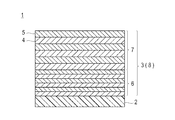
- Patent Document 1 discloses a low-refractive-index dielectric film and a high-refractive-index film.
- a near-infrared reflective substrate is disclosed in which a near-infrared reflective film in which dielectric films are alternately laminated is formed on a transparent plate glass.
- the near-infrared reflective film is defined by JIS R3106-1998, which is a plate glass in which a dielectric film is laminated with at least 4 layers and not more than 11 layers on at least one surface, and the near-infrared reflective film is formed.
- the visible light transmittance is 70% or more, and it has a maximum value of reflection exceeding 50% in the wavelength region from 900 nm to 1400 nm.
- the near-infrared reflective film includes (1) the dielectric films counted in order from the plate glass surface, the maximum value of the even-numbered layer refractive index is n emax , the minimum value is n emin, and the maximum refractive index of the odd-numbered layer is when the value n omax, the minimum value was n Omin, when n emax ⁇ n omin or n omax ⁇ n emin conditions, and the (2) i-th refractive index n i and a thickness of the layer was set to d i
- the condition of 225 nm ⁇ n i ⁇ d i ⁇ 350 nm is satisfied.
- near-infrared reflective film near-infrared reflective film
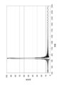
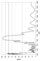
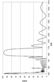
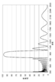
- a sharp reflection peak appears in the near-infrared region, but a reflection peak (particularly, high reflection and low reflection are repeated depending on the wavelength).
- a so-called ripple peak may appear. Therefore, not only near-infrared light but also visible light is reflected, and the transparency of the infrared reflective film may not be sufficiently secured.
- Patent Document 2 discloses an infrared ray in which a multilayer film in which a plurality of high refractive index thin films made of a high refractive index material and low refractive index thin films made of a low refractive index material are alternately stacked is formed on a transparent substrate. A cut filter is disclosed.
- the multilayer film is composed of 16 to 32 layers of the thin film, the first layer from the transparent substrate side of the multilayer film is the high refractive index thin film, and the final layer of the multilayer film is The low refractive index thin film.
- the first layer and the second layer are formed with an optical film thickness of ( ⁇ / 4) or more from the transparent substrate side of the multilayer film, and the transparent substrate of the multilayer film is formed.
- the third layer or the predetermined layer is formed with an optical film thickness of ( ⁇ / 4) or less, and the layer between the predetermined layer and the final layer is an optical film of ( ⁇ / 4) or more.
- the final layer is formed with an optical film thickness of ( ⁇ / 4) or less. That is, the multilayer films constituting the infrared cut filter are classified into four layer groups, and the value of the optical film thickness is shifted from ⁇ / 4 for each of the four layer groups.
- an object of the present invention is to provide a near-infrared reflective film that suppresses a reflection peak such as a ripple that may occur in the visible region and exhibits an excellent reflection peak in the near-infrared region.
- the present inventors have shifted the optical film thicknesses of the high refractive index layer and the low refractive index layer constituting the near-infrared reflective film, and have changed the thicknesses of the high refractive index layer and the low refractive index layer.
- the near-infrared reflective film which shows a suitable reflective peak was obtained, and came to complete this invention.
- a support A dielectric multilayer film in which high refractive index layers and low refractive index layers are alternately stacked, disposed on the support; A near-infrared reflective film having Any of the high refractive index layer and the low refractive index layer adjacent to the high refractive index layer,
- the dielectric multilayer film includes a first layer composed of at least three of a high refractive index layer (refractive index n 1 H, thickness d 1 H) and a low refractive index layer (refractive index n 1 L, thickness d 1 L).
- the optical film thickness (d 1 H ⁇ n 1 H) of the high refractive index layer and the optical film thickness (d 1 L ⁇ n 1 L) of the low refractive index layer of the first dielectric film group are:
- the near-infrared reflective film according to any one of (1) to (4), (6) The near-infrared reflective film according to any one of (1) to (5), wherein the dielectric multilayer film includes a resin; (7) The near-infrared reflective film according to (6), wherein the dielectric multilayer film further includes metal oxide particles; (8) A near-infrared reflective glass in which the near-infrared reflective film according to any one of (1) to (7) is bonded to the surface of a glass plate.
- the present invention can provide a near-infrared reflective film that suppresses reflection peaks such as ripples that may occur in the visible region and exhibits excellent near-infrared region reflection peaks.
- FIG. 3 is a graph showing a reflection peak of an infrared reflective film manufactured in Example 1.
- FIG. 5 is a graph showing a reflection peak of an infrared reflective film produced in Comparative Example 1.
- 6 is a graph showing a reflection peak of an infrared reflective film produced in Comparative Example 3.
- 6 is a graph showing a reflection peak of an infrared reflective film produced in Example 2.
- FIG. 10 is a graph showing a reflection peak of an infrared reflective film produced in Comparative Example 5.
- 6 is a graph showing a reflection peak of an infrared reflective film manufactured in Example 6.
- FIG. 6 is a graph showing a reflection peak of an infrared reflective film manufactured in Example 7.
- FIG. It is a graph which shows the reflection peak of the infrared reflective film manufactured in Example 8.
- FIG. 10 is a graph showing a reflection peak of an infrared reflective film produced in Comparative Example 8.
- One embodiment of the present invention relates to a near-infrared reflective film having a support and a dielectric multilayer film in which high-refractive index layers and low-refractive index layers are alternately stacked, which are disposed on the support.
- the near-infrared reflective film is characterized in that the arbitrary high refractive index layer and the low refractive index layer adjacent to the high refractive index layer satisfy the following formula.
- dH represents the thickness of the high refractive index layer
- nH represents the refractive index of the high refractive index layer
- dL represents the thickness of the low refractive index layer
- nL represents the thickness of the low refractive index layer.
- DH ⁇ nH represents the optical film thickness of the high refractive index layer
- dL ⁇ nL represents the optical film thickness of the low refractive index layer.
- the dielectric multilayer film includes at least three of a high refractive index layer (refractive index n 1 H, thickness d 1 H) and a low refractive index layer (refractive index n 1 L, thickness d 1 L).
- the first dielectric film group, a high refractive index layer (refractive index n 2 H, thickness d 2 H) and a low refractive index layer (refractive index) in contact with the surface opposite to the support of the first dielectric film group n 2 L, thickness d 2 L) each having at least three dielectric film groups, and the dielectric film group set satisfying the following formula: Features.
- FIG. 1 is a schematic cross-sectional view schematically showing a near-infrared reflective film according to an embodiment.
- the near-infrared reflective film 1 has a dielectric multilayer film 3 disposed on a support 2 made of polycarbonate.
- the dielectric multilayer film 3 is composed of alternately a low refractive index layer 4 formed by sputtering magnesium fluoride (MgF 2 ) and a high refractive index layer 5 formed by sputtering titanium oxide (TiO 2 ). 12 layers are stacked. Therefore, the odd-numbered layer counted from the support 2 becomes the low refractive index layer 4, and the even-numbered layer becomes the high refractive index layer 5.
- MgF 2 sputtering magnesium fluoride
- TiO 2 titanium oxide
- the refractive index (nL) of the low refractive index layer is 1.33
- the refractive index (nH) of the high refractive index layer is 2.70
- the thickness (nL) of the low refractive index layer is The first, third and fifth layers from the support 2 are 197 nm, and the seventh, ninth and eleventh layers are 211 nm.
- the thickness (dH) of the high refractive index layer is 102 nm for the second, fourth, and sixth layers counted from the support 2 and is 109 nm for the eighth, tenth, and twelfth layers.
- an optical film of an arbitrary high refractive index layer and a low refractive index layer adjacent to the high refractive index layer for example, a second high refractive index layer and a third low refractive index layer counted from the support.
- the optical film thickness (nH ⁇ dH) of the high refractive index layer is 275
- the optical film thickness (nL ⁇ dL) of the low refractive index layer is 262.
- (NH ⁇ dH) / (nL ⁇ dL) is 1.05.
- the optical film thickness (refractive index ⁇ thickness) of the eighth high refractive index layer and the ninth low refractive index layer counted from the support is the optical film thickness (nH ⁇ dH) of the high refractive index layer.
- the optical film thickness (nL ⁇ dL) of the low refractive index layer is 281, the ratio (nH ⁇ dH) / (nL ⁇ dL) is 1.05.
- the dielectric multilayer film includes two dielectric film groups, that is, (1) a high refractive index layer having the same refractive index (n 1 H: 2.70) and thickness (d 1 H: 102 nm), And the first dielectric film group 6 in which three low refractive index layers having the same refractive index (n 1 L: 1.33) and thickness (d 1 L: 197 nm) are laminated, and (2 ) A high refractive index layer in contact with the surface opposite to the support of the first dielectric film group, both having the same refractive index (n 2 H: 2.70) and thickness (d 2 H: 109 nm); And a dielectric film comprising a second dielectric film group 7 in which three low refractive index layers having the same refractive index (n 2 L: 1.33) and thickness (d 2 L: 211 nm) are respectively laminated.
- the thickness ratio (d 2 H / d 1 H) between the high refractive index layers between the first dielectric film group 6 and the second dielectric film group 7 is 1.07.
- the ratio of the thickness between the low refractive index layers (d 2 L / d 1 L) is 1.07.
- the second relative to the optical film thickness of the high refractive index layer of the first dielectric film group is described.
- the ratio of the optical film thickness of the high refractive index layer of the dielectric film group (d 2 H ⁇ n 2 H / d 1 H ⁇ n 1 H) is 1.07
- the low refractive index layer of the first dielectric film group The ratio of the optical film thickness of the low refractive index layer in the second dielectric film group to the optical film thickness (d 2 L ⁇ n 2 L / d 1 L ⁇ n 1 L) is 1.07.
- the near-infrared reflective film 1 in FIG. 1 it is possible to suppress a reflection peak such as a ripple that may occur in the visible region and to show an excellent reflection peak in the near-infrared region.
- the support applied to the infrared reflective film of the present invention is not particularly limited as long as it is transparent, and a known resin film can be used.
- a known resin film can be used.
- PE polyethylene
- PP polypropylene
- PS polystyrene
- PC polyethylene terephthalate
- PET polybutylene terephthalate
- PBT polyethylene naphthalate
- PEN phthalate
- polysulfone polyethersulfone
- polyetheretherketone polyimide
- aromatic polyamide and polyetherimide.
- polyethylene terephthalate (PET), polyethylene naphthalate (PEN), polycarbonate (PC), and the like are preferably used from the viewpoints of cost and availability.
- the support preferably has a visible region transmittance of 85% or more, more preferably 90% or more, as shown in JIS R3106-1998. It is preferable that the visible light transmittance of the support is 85% or more because the transmittance in the visible region shown in JIS R3106-1998 when used as a near-infrared reflective film can be 50% or more.
- the support using the resin film may be an unstretched film or a stretched film.
- a resin film having crystallinity such as PET or PEN
- the strength is improved.
- a film that is heat-set after stretching is preferred.
- the support using the resin film can be produced by a conventionally known general method.
- an unstretched film that is substantially amorphous and not oriented can be produced by melting a resin as a material with an extruder, extruding it with an annular die or a T-die, and quenching.
- the unstretched film is subjected to a known method such as uniaxial stretching, tenter-type sequential biaxial stretching, tenter-type simultaneous biaxial stretching, tubular-type simultaneous biaxial stretching, and the resin film flow (vertical axis) direction, and / or
- a stretched film can be produced by stretching in the direction perpendicular to the flow direction of the resin film (horizontal axis).
- the draw ratio in this case can be appropriately selected according to the resin as the raw material of the support, but is preferably 2 to 10 times in the vertical axis direction and the horizontal axis direction.
- the thickness of the support according to the present invention is preferably 5 to 300 ⁇ m, more preferably 15 to 150 ⁇ m.
- the support may be a laminate of two or more, and in this case, the type of the support may be the same or different.
- the support may be subjected to relaxation treatment and off-line heat treatment from the viewpoint of dimensional stability.
- the relaxation treatment is performed in the process from the heat setting in the stretching process of the resin film to the winding in the transversely stretched tenter or after exiting the tenter.
- the relaxation treatment is preferably carried out at a treatment temperature of 80 to 200 ° C., more preferably 100 to 180 ° C.
- the relaxation rate is preferably processed to 0.1 to 10%, more preferably 2 to 6%.
- the relaxed support can be further subjected to off-line heat treatment to improve heat resistance and further improve dimensional stability.
- the support is provided with an undercoat layer on one side or both sides in the film forming process.
- the undercoat layer can be formed in-line or after film formation.
- Examples of the method for forming the undercoat layer include a method of applying an undercoat layer coating solution and drying the obtained coating film.
- the undercoat layer coating solution usually contains a resin.
- the resin include polyester resins, acrylic-modified polyester resins, polyurethane resins, acrylic resins, vinyl resins, vinylidene chloride resins, polyethyleneimine vinylidene resins, polystyrene butadiene resins, polyethyleneimine resins, polyvinyl alcohol, and gelatin.
- a known additive may be further added to the undercoat layer coating solution.
- the coating amount of the undercoat layer coating solution is preferably applied so as to be about 0.01 to 2 g / m 2 in a dry state.
- the coating method of the undercoat layer coating solution is not particularly limited, and known methods such as a roll coating method, a gravure coating method, a knife coating method, a dip coating method, and a spray coating method can be used.
- the obtained coating film may be stretched, and usually an undercoat layer can be formed by drying at 80 to 120 ° C. while performing lateral stretching in a tenter after coating the coating solution.
- the undercoat layer may have a single layer structure or a laminated structure.
- the support according to the present invention further comprises a conductive layer, an antistatic layer, a gas barrier layer, an easy adhesion layer (adhesion layer), an antifouling layer, a deodorizing layer, a droplet layer, an easy slip layer, a hard coat layer, and an abrasion resistance.
- a conductive layer used for adhesive layers, antireflection layers, electromagnetic wave shielding layers, ultraviolet absorbing layers, infrared absorbing layers, printed layers, fluorescent light emitting layers, hologram layers, release layers, adhesive layers, colored layers (visible light absorbing layers), and laminated glass
- You may have well-known functional layers, such as an interlayer film layer.
- the total film thickness of the support and the intermediate layer is preferably 5 to 500 ⁇ m, more preferably 25 to 250 ⁇ m. preferable.
- the dielectric multilayer film has a configuration in which high refractive index layers and low refractive index layers are alternately stacked.
- refractive index layers having different refractive indexes are alternately laminated, when near infrared light is irradiated from the substrate side or the dielectric multilayer film side, at least a part of the infrared light is It can reflect and exhibit an infrared reflection effect.
- the dielectric multilayer film is formed by alternately stacking high refractive index layers and low refractive index layers having different refractive indexes.
- the high refractive index layer and the low refractive index layer constituting the dielectric multilayer film may be the same or different. Whether the refractive index layer constituting the dielectric multilayer film is a high refractive index layer or a low refractive index layer is determined by comparing the refractive index with the adjacent refractive index layer.
- the reference layer is a high refractive index layer (the adjacent layer has a low refractive index). It is judged to be a rate layer.
- the refractive index of the adjacent layer is higher than that of the reference layer, it is determined that the reference layer is a low refractive index layer (the adjacent layer is a high refractive index layer). Therefore, whether the refractive index layer is a high refractive index layer or a low refractive index layer is a relative one determined by the relationship with the refractive index of the adjacent layer. Depending on the relationship, it can be a high refractive index layer or a low refractive index layer. Therefore, the structure of the refractive index layer that can include both will be described in detail below.
- refractive index layer a refractive index layer formed using a dry film forming method, a refractive index layer formed by extrusion molding of a resin, and a refractive index layer formed using a wet film forming method Is mentioned.
- the refractive index layer can be formed by evaporating a dielectric material.
- the material that can be used for the dry film-forming method is not particularly limited, but is preferably a transparent dielectric material.
- transparent dielectric materials include titanium oxide (TiO 2 ), zinc oxide (ZnO), zirconium oxide (ZrO 2 ), niobium oxide (Nb 2 O 5 ), aluminum oxide (Al 2 O 3 ), silicon oxide (SiO 2 ), calcium fluoride (CaF 2 ), magnesium fluoride (MgF 2 ), indium tin oxide (ITO), antimony tin oxide (ATO), and the like.
- titanium oxide, zinc oxide, silicon oxide, and magnesium fluoride it is preferable to use titanium oxide, zinc oxide, silicon oxide, and magnesium fluoride.
- preferable high refractive index layer-low refractive index layer material combinations are titanium oxide-silicon oxide, titanium oxide-magnesium fluoride, and zinc oxide-silicon oxide.
- Examples of a method for forming a refractive index layer formed by resin extrusion include a method in which a molten resin obtained by melting a resin is extruded onto a casting drum from a multilayer extrusion die and then rapidly cooled. At this time, after extruding and cooling the molten resin, the resin sheet may be stretched.
- the stretching ratio of the resin can be appropriately selected according to the resin, but is preferably 2 to 10 times in the vertical axis direction and the horizontal axis direction.
- the resin is not particularly limited as long as it is a thermoplastic resin.
- a thermoplastic resin for example, polyalkylene resins, polyester resins, polycarbonate resins, (meth) acrylic resins, amide resins, silicone resins, fluorine resins, etc. Is mentioned.
- polyalkylene resin examples include polyethylene (PE) and polypropylene (PP).
- polyester resin examples include polyester resins having a dicarboxylic acid component and a diol component as main components.
- the dicarboxylic acid component includes terephthalic acid, isophthalic acid, phthalic acid, 2,6-naphthalenedicarboxylic acid, 2,7-naphthalenedicarboxylic acid, diphenylsulfone dicarboxylic acid, diphenyl ether dicarboxylic acid, diphenylethanedicarboxylic acid, cyclohexane.
- Examples include dicarboxylic acid, diphenyldicarboxylic acid, diphenylthioether dicarboxylic acid, diphenylketone dicarboxylic acid, and phenylindane dicarboxylic acid.
- the diol component include ethylene glycol, propylene glycol, tetramethylene glycol, 1,4-butanediol, cyclohexanedimethanol, 2,2-bis (4-hydroxyphenyl) propane, and 2,2-bis (4- Hydroxyethoxyphenyl) propane, bis (4-hydroxyphenyl) sulfone, bisphenol fluorange hydroxyethyl ether, diethylene glycol, neopentyl glycol, hydroquinone, cyclohexanediol and the like.
- PET polyethylene terephthalate
- PBT polybutylene terephthalate
- polycarbonate resin examples include a reaction product of bisphenol A or its derivative bisphenol and phosgene or phenyl dicarbonate.
- Examples of the (meth) acrylic resin include acrylic acid, methacrylic acid, acrylonitrile, methacrylonitrile, methyl (meth) acrylate, ethyl (meth) acrylate, butyl (meth) acrylate, and (meth) acrylic acid-2.
- amide resin examples include aliphatic amide resins such as 6,6-nylon, 6-nylon, 11-nylon, 12-nylon, 4,6-nylon, 6,10-nylon, and 6,12-nylon;
- aromatic polyamide such as an aromatic diamine such as phenylenediamine and an aromatic dicarboxylic acid such as terephthaloyl chloride or isophthaloyl chloride or a derivative thereof may be used.
- silicone resin examples include resins containing a siloxane bond having an organic group such as an alkyl group or an aromatic group as a structural unit.
- the alkyl group is not particularly limited, and examples thereof include a methyl group, an ethyl group, a propyl group, an isopropyl group, a butyl group, an iobutyl group, a sec-butyl group, a tert-butyl group, a pentyl group, and a hexyl group.
- the aromatic group is not particularly limited, and examples thereof include a phenyl group, a tolyl group, a xylyl group, and a benzyl group.
- those having a methyl group and / or a phenyl group are preferable, and dimethylpolysiloxane, methylphenylpolysiloxane, diphenylpolysiloxane, and modified products thereof are more preferable.
- fluororesin examples include homopolymers or copolymers such as tetrafluoroethylene, hexafluoropropylene, chlorotrifluoroethylene, vinylidene fluoride, vinyl fluoride, and perfluoroalkyl vinyl ether.
- the above-described resins may be used alone or in combination of two or more.
- a preferable combination of materials of a high refractive index layer and a low refractive index layer includes PET-PEN and the like.
- the refractive index layer can be formed by a method of sequentially applying and drying a coating solution, a method of applying and drying a coating solution in multiple layers, or the like.
- the material contained in the coating solution includes a resin.
- the resin is not particularly limited as long as it is soluble in a solvent.
- polyester resin polycarbonate resin, (meth) acrylic resin, amide resin, silicone resin, fluorine resin, silicon-containing polymer , Polyvinyl alcohol, polyvinyl pyrrolidone, polyethylene oxide, cellulose resins, gelatins, thickening polysaccharides and the like.
- resins specific examples of resins that are preferably used are as follows.
- silicon-containing polymer examples include polycarbosilane, polyorganoborosilazane, polymetalloxane, polyborosiloxane, and polycarbosilazane.
- polyvinyl alcohol examples include unmodified polyvinyl alcohol and modified polyvinyl alcohol.
- the average degree of polymerization of the unmodified polyvinyl alcohol is preferably from 200 to 4000, more preferably from 500 to 3000, and even more preferably from 1000 to 2500 from the viewpoints of flexibility and durability.
- the degree of saponification of the unmodified polyvinyl alcohol is preferably about 60 to 100 mol%, more preferably 78 to 99.8 mol%, still more preferably 80 to 96 mol%.
- Such saponified polyvinyl alcohol can be produced by radical polymerization of vinyl acetate and appropriately saponifying the resulting polyvinyl acetate.
- the desired unmodified polyvinyl alcohol can be produced by appropriately controlling the degree of polymerization and the degree of saponification by a method known per se.
- a commercially available product may be used as the partially saponified polyvinyl alcohol.
- Examples of commercially available unmodified polyvinyl alcohol include Gohsenol EG05, EG25 (manufactured by Nippon Synthetic Chemical Industry Co., Ltd.), PVA203 (manufactured by Kuraray Co., Ltd.), PVA204 (manufactured by Kuraray Co., Ltd.), PVA205 (manufactured by Kuraray Co., Ltd.), JP -04 (manufactured by Nippon Vinegar-Poval Corporation), JP-05 (manufactured by Nippon Vinegar-Poval Corporation), and the like.
- Modified polyvinyl alcohol is obtained by subjecting the above-mentioned unmodified polyvinyl alcohol to one or more of arbitrary modification treatments.
- arbitrary modification treatments include amine-modified polyvinyl alcohol, ethylene-modified polyvinyl alcohol, carboxylic acid-modified polyvinyl alcohol, diacetone-modified polyvinyl alcohol, thiol-modified polyvinyl alcohol, and acetal-modified polyvinyl alcohol.
- modified polyvinyl alcohols such as polyvinyl alcohol having a terminal cation modified, an anion modified polyvinyl alcohol having an anionic group, and nonionic modified polyvinyl alcohol may also be used. Of these, acetal-modified polyvinyl alcohol is preferred.
- acetal-modified polyvinyl alcohol examples include polyvinyl formal, polyvinyl ethanal, polyvinyl propanal, polyvinyl butyral (polyvinyl butanal), polyvinyl valeral, polyvinyl hexal, polyvinyl heptanal, polyvinyl 2-ethyl hexal, polyvinyl cyclohexal, polyvinyl Glutar, polyvinyl benzal, polyvinyl 2-methyl benzal, polyvinyl 3-methyl benzal, polyvinyl 4-methyl benzal, polyvinyl p-hydroxy benzal, polyvinyl m-hydroxy benzal, polyvinyl phenyl acetal, polyvinyl ⁇ -Phenylpropanal and the like.
- polyvinyl alcohol acetalized with C1-C5 aldehyde (formaldehyde, acetaldehyde, propionaldehyde, butyraldehyde, valeraldehyde, etc.), that is, polyvinyl formal, polyvinyl ethanal, polyvinyl propanal, polyvinyl butyral, polyvinyl valeral
- polyvinyl alcohol acetalized with C2 to C4 aldehydes that is, polyvinyl formal, polyvinyl ethanal, polyvinyl propanal, and polyvinyl butyral.
- the degree of acetalization of the acetal-modified polyvinyl alcohol is preferably 40 to 85 mol%, more preferably 55 to 80 mol%, and further preferably 60 to 75 mol%.
- the degree of acetalization can be measured by an infrared absorption spectrum (IR) method using FT-IR (HORIBA, Ltd., FREEEXACT-II, FT-720).
- IR infrared absorption spectrum
- FT-IR HORIBA, Ltd., FREEEXACT-II, FT-720.
- the amount of the hydroxyl group is preferably 15 to 35 mol% from the viewpoint of adhesiveness and flexibility.
- the mass average molecular weight of the acetal-modified polyvinyl acetal is preferably 90000 to 400000, more preferably 90000 to 370000, and further preferably 90000 to 340000.
- the mass average molecular weight is a gel permeation chromatography (GPC) analyzer using a TSKgel GMHxL, TSKgel G4000HxL or TSKgel G2000HxL (Tosoh Corporation) column (solvent: tetrahydrofuran (THF)).
- GPC gel permeation chromatography
- the acetal-modified polyvinyl alcohol can be obtained by acetalizing unmodified polyvinyl alcohol with a C1 to C10 aldehyde.
- the C1 to C10 aldehyde is not particularly limited, but is not limited to formaldehyde, acetaldehyde, propionaldehyde, butyraldehyde, amylaldehyde, hexylaldehyde, heptylaldehyde, 2-ethylhexylaldehyde, cyclohexylaldehyde, furfural, glyoxal, glutaraldehyde, benzaldehyde, Examples thereof include 2-methylbenzaldehyde, 3-methylbenzaldehyde, 4-methylbenzaldehyde, p-hydroxybenzaldehyde, m-hydroxybenzaldehyde, phenylacetaldehyde, ⁇ -phenylpropionaldehyde
- C1 to C5 aldehydes such as formaldehyde, acetaldehyde, propionaldehyde, butyraldehyde, and amylaldehyde are preferable, and C2 to C4 aldehydes such as acetaldehyde, propionaldehyde, and butyraldehyde are more preferable.
- C1 to C5 aldehydes such as formaldehyde, acetaldehyde, propionaldehyde, butyraldehyde, and amylaldehyde are preferable
- C2 to C4 aldehydes such as acetaldehyde, propionaldehyde, and butyraldehyde are more preferable.
- These aldehydes may be used alone or in admixture of two or more.
- modified polyvinyl alcohols commercially available products may be used, or those produced by methods known in the art may be used.
- commercially available acetal-modified polyvinyl alcohols include Denkabutyral 3000-1, 5000-A, 6000-C, 6000-CS (manufactured by Denki Kagaku Kogyo Co., Ltd.), ESREC BX-1, BX-5, KS-5 ( Sekisui Chemical Co., Ltd.) can be used.
- the polyvinyl pyrrolidone is a polymer of N-vinyl-2-pyrrolidone.
- the polyvinyl pyrrolidone has a viscosity average molecular weight of preferably 5,000 to 800,000, more preferably 10,000 to 630000, and further preferably 15,000 to 340000.
- the polyethylene oxide is a polymer of ethylene oxide.
- the mass average molecular weight of polyethylene oxide is preferably from 1,000 to 800,000, more preferably from 5,000 to 630000, and even more preferably from 10,000 to 340000.
- Examples of the cellulose-based resin include an internal plasticized cellulose resin and an external plasticized cellulose resin, and it is preferable to use an internal plasticized cellulose resin.
- Examples of the internally plasticized cellulose resin include cellulose ester, cellulose carbamate, and cellulose ether.
- cellulose esters examples include organic acid esters and inorganic acid esters.
- the cellulose ester may be a mixed acid ester of the organic acid and the inorganic acid.
- organic acid esters include cellulose alkyl carboxylic acid esters and cellulose aromatic carboxylic acid esters.
- examples of the cellulose alkyl carboxylic acid ester include cellulose acetate, cellulose propionate, cellulose butyrate, cellulose pentanoate, cellulose hexanoate, cellulose acetate propionate, cellulose acetate butyrate, cellulose acetate pentanoate, and cellulose acetate.
- Cellulose C2-C6 alkyl ester such as hexanoate
- C1-C6 alkyl cellulose C2-C6 alkyl ester such as methyl cellulose acetate and ethyl cellulose acetate
- C1-C6 haloalkyl such as dichloromethyl cellulose acetate, trichloromethyl cellulose propionate and trifluoromethyl cellulose acetate
- examples thereof include cellulose C1-C6 alkyl esters.
- the cellulose aromatic carboxylic acid ester include cellulose C7 to C12 aromatic esters such as cellulose phthalate, cellulose benzoate, and cellulose-4-methylbenzoate.
- examples of the inorganic acid ester include cellulose phosphate and cellulose sulfate.
- cellulose C2-C6 alkyl ester is preferable from the viewpoint of transparency, and acetyl C3-C6 such as cellulose acetate propionate, cellulose acetate butyrate, cellulose acetate pentanoate, cellulose acetate hexanoate and the like. More preferred is acylcellulose.
- Cellulose carbamates include cellulose C1-C6 alkyl carbamates such as cellulose ethyl carbamate; cellulose C6-C12 aryl carbamates such as cellulose phenyl carbamate; C1-C6 alkyl cellulose C1-C6 alkyl carbamates (cellulose ether carbamate) such as ethyl cellulose propyl carbamate; Examples thereof include C1-C6 alkyl cellulose C6-C12 aryl carbamate (cellulose ether carbamate) such as ethyl cellulose phenyl carbamate. Of these, C1-C6 alkyl cellulose C6-C12 aryl carbamates (cellulose ether carbamates) such as ethyl cellulose phenyl carbamate are preferably used.
- cellulose ethers examples include C1-C10 alkyl celluloses such as methyl cellulose, ethyl cellulose, propyl cellulose, and pentyl cellulose; cyano C1-C10 alkyl celluloses such as cyanoethyl cellulose and cyanopropyl cellulose; C6-C12 aryl-C1-C4 such as benzyl cellulose.
- Examples include alkyl cellulose (aralkyl cellulose). Of these, cyano C1-C10 alkyl alcohols such as cyanoethyl cellulose and cyanopropyl cellulose are preferred.
- cellulose esters and cellulose ethers are preferably used, and cellulose esters are more preferably used.
- the average degree of polymerization of the cellulose resin is not particularly limited, but is preferably 50 to 8000, more preferably 100 to 7000, and further preferably 200 to 6000.
- the average substitution degree of the cellulose resin is preferably 1 to 3, more preferably 1.3 to 3, further preferably 1.5 to 3, and preferably 2 to 3. Is particularly preferred.
- the cellulose-based resin may be synthesized by a known method or may be commercially available.
- a method for synthesizing a cellulose-based resin (a) a method in which cellulose is reacted with a carboxylic acid, alcohol, isocyanate, etc. to internal plasticize, and (b) a plasticizer is added to the cellulose to external plasticize. And (c) a method of combining (a) and (b).
- gelatins examples include various gelatins that have been widely used in the field of silver halide photographic materials. More specifically, acid-treated gelatin, alkali-treated gelatin, enzyme-treated gelatin, and derivatives thereof can be mentioned.
- the general method for producing gelatin is well known and is described, for example, in T.W. H. James: The Theory of Photographic Process 4th. Ed. 1977 (Machillan), 55 pages, Science Photo Handbook (above), pages 72-75 (Maruzen), Photographic Engineering Basics-Silver Salt Photography, pages 119-124 (Corona) can be referred to. Also, Research Disclosure Magazine Vol. 176, No. The gelatin described in IX page of 17643 (December, 1978) can be mentioned.
- the thickening polysaccharide is not particularly limited and includes generally known natural simple polysaccharides, natural complex polysaccharides, synthetic simple polysaccharides, and synthetic complex polysaccharides. Specifically, pectin, galactan (eg, agarose, agaropectin, etc.), galactomannoglycan (eg, locust bean gum, guaran, etc.), xyloglucan (eg, tamarind gum, tamarind seed gum, etc.), glucomannoglycan (Eg, salmon mannan, wood-derived glucomannan, xanthan gum, etc.), galactoglucomannoglycan (eg, softwood-derived glycan), arabinogalactoglycan (eg, soybean-derived glycan, microorganism-derived glycan, etc.) (E.g., gellan gum), glycosaminoglycans (e.g., hyaluronic acid,
- modified polyvinyl alcohol particularly acetal-modified polyvinyl alcohol
- cellulose resin e.g., cellulose-modified polyvinyl alcohol
- the above-described resins may be used alone or in combination of two or more.
- the coating solution may further contain metal oxide particles together with the resin described above.
- the dielectric material etc. which can be used by the dry-type film-forming method are mentioned.
- titanium oxide (TiO 2 ) and silicon oxide (SiO 2 ) are preferably used.
- titanium oxide TiO 2
- rutile type titanium oxide having a high refractive index and low catalytic activity. If the catalytic activity is low, side reactions (photocatalytic reactions) that occur in the refractive index layer and adjacent layers can be suppressed, and the weather resistance can be increased.
- a water-based titanium oxide sol having a pH of 1.0 to 3.0 and having a positive zeta potential of titanium particles is hydrophobized so that it can be dispersed in an organic solvent.
- examples of the method for preparing the aqueous titanium oxide sol include Japanese Patent Laid-Open Nos. 63-17221, 7-819, 9-165218, 11-43327, and 63. Reference can be made to the matters described in JP-A-17221, JP-A-7-819, JP-A-9-165218, JP-A-11-43327, and the like.
- the production method according to the step (2) is a step of treating titanium dioxide hydrate with at least one basic compound selected from the group consisting of alkali metal hydroxides and alkaline earth metal hydroxides.
- the titanium dioxide dispersion obtained in (1) is treated with a carboxylic acid group-containing compound and an inorganic acid.
- an aqueous sol of titanium oxide having a pH adjusted to 1.0 to 3.0 with an inorganic acid in the step (2) can be used.
- Examples of the silicon oxide (SiO 2 ) include synthetic amorphous silica and colloidal silica. Of these, acidic colloidal silica sol is more preferably used, and colloidal silica sol dispersed in water and / or an organic solvent is more preferably used.
- the colloidal silica can be obtained by heating and aging a silica sol obtained by metathesis with an acid of sodium silicate or the like and passing through an ion exchange resin layer.
- Such colloidal silica is disclosed in, for example, JP-A-57-14091, JP-A-60-219083, JP-A-60-218904, JP-A-61-20792, JP-A-61- No. 188183, No. 63-17807, No.
- Colloidal silica may be a synthetic product or a commercially available product.
- the metal oxide particles may be used alone or in combination of two or more.
- the average particle diameter of the metal oxide particles is preferably 2 to 100 nm, more preferably 3 to 50 nm, and further preferably 4 to 30 nm.
- the average particle size of the metal oxide particles is determined by observing the particles themselves or the particles appearing on the cross section or surface of the refractive index layer with an electron microscope, measuring the particle size of 1,000 arbitrary particles, It is obtained as a value (number average).
- the particle diameter of each particle is represented by a diameter assuming a circle equal to the projected area.
- the content of the metal oxide particles is preferably 30 to 90% by mass and more preferably 40 to 80% by mass with respect to the total mass of the formed refractive index layer. It is preferable that the content of the metal oxide particles is 30% by mass or more because a desired refractive index can be obtained. Further, it is preferable that the content of the metal oxide particles is 90% by mass or less because flexibility of the film can be obtained and film formation becomes easy.
- anionization treatment or cationization treatment may be performed so that the metal oxide particles have the same ionicity (charge). preferable.
- anionization treatment or cationization treatment By performing anionization treatment or cationization treatment, a repulsive force is generated between the two types of metal oxide particles, and thus, for example, at the layer interface during the multilayer coating of the low refractive index layer and the high refractive index layer. Aggregation or the like can hardly occur.
- anionization treatment of metal oxide particles for example, anion treatment of titanium oxide is exemplified.
- the titanium oxide particles can be anionized by coating with a silicon-containing hydrated oxide.
- the coating amount of the silicon-containing hydrated compound is usually 3 to 30% by mass, preferably 3 to 10% by mass, and more preferably 3 to 8% by mass. When the coating amount is 30% by mass or less, a desired refractive index of the high refractive index layer can be obtained, and when the coating amount is 3% or more, particles can be stably formed.
- the cationization treatment of the metal oxide particles can be performed by using, for example, a cationic compound.
- the cationic compound include a cationic polymer and a polyvalent metal salt, and a polyvalent metal salt is preferred from the viewpoint of adsorption power and transparency.
- polyvalent metal salts include aluminum, calcium, magnesium, zinc, iron, strontium, barium, nickel, copper, scandium, gallium, indium, titanium, zirconium, tin, lead, and other metal hydrochlorides, sulfates, nitrates, Examples include acetate, formate, succinate, malonate, chloroacetate and the like.
- water-soluble aluminum compounds water-soluble calcium compounds, water-soluble magnesium compounds, water-soluble zinc compounds, and water-soluble zirconium compounds are preferably used, and water-soluble aluminum compounds and water-soluble zirconium compounds are more preferably used.
- the water-soluble aluminum compound include polyaluminum chloride (basic aluminum chloride), aluminum sulfate, basic aluminum sulfate, aluminum potassium sulfate (alum), ammonium aluminum sulfate (ammonium alum), sodium aluminum sulfate, aluminum nitrate, Examples thereof include aluminum phosphate, aluminum carbonate, polysulfuric acid aluminum silicate, aluminum acetate, and basic aluminum lactate.
- the water solubility in the water-soluble polyvalent metal compound means that it dissolves in water at 20 ° C. in an amount of 1% by mass or more, more preferably 3% by mass or more.
- the coating amount of the cationic compound varies depending on the shape and particle size of the metal oxide particles, but is preferably 1% by mass to 15% by mass with respect to the metal oxide particles.
- preferable high refractive index layer-low refractive index layer material combinations include polyvinyl alcohol, titanium oxide-polyvinyl alcohol and silicon oxide-polyvinyl alcohol, and zirconium oxide-gelatin and silicon oxide-polyvinyl alcohol. Is mentioned.
- the above-mentioned refractive index layer may further contain a known additive.
- the additive include a curing agent, an amino acid, and an emulsion resin.
- the curing agent When the refractive index layer contains a resin, the curing agent has a function of curing the resin. By curing, water resistance can be imparted to the refractive index layer.
- the curing agent that can be used is not particularly limited as long as it causes a curing reaction with the resin.
- boric acid and its salt boron atom is a central atom. It is preferable to use orthoboric acid, diboric acid, metaboric acid, tetraboric acid, pentaboric acid and octaboric acid or salts thereof. Boric acid and its salt may be used alone or in admixture of two or more, and it is particularly preferable to use a mixed aqueous solution of boric acid and borax.
- curing agent examples include, for example, diglycidyl ethyl ether, ethylene glycol diglycidyl ether, 1,4 monobutanediol diglycidyl ether, 1,6-diglycidyl cyclohexane, N, N— Epoxy curing agents such as diglycidyl-4-glycidyloxyaniline, sorbitol polyglycidyl ether, glycerol polyglycidyl ether; aldehyde curing agents such as formaldehyde and glycoxal; 2,4-dichloro Active halogen type curing agents such as -4-hydroxy-1,3,5-S-triazine; 1.3.5 Active vinyl type such as tris-acryloyl-hexahydro-S-triazine and
- examples of the curing agent include vinyl sulfone compounds, urea-formalin condensates, melanin-formalin condensates, epoxy compounds, aziridine compounds, active olefins, isocyanate compounds, and the like.
- Organic hardeners, inorganic polyvalent metal salts such as chromium, aluminum, and zirconium may be used.
- the total amount of curing agent used is preferably 1 to 600 mg per gram of resin.
- Emulsion resin An emulsion resin is usually a resin formed by fusing a polymer dispersed in a coating solution during film formation.
- An emulsion as a raw material for the emulsion resin is obtained by emulsion polymerization of an oil-soluble monomer using a polymer dispersant or the like.
- Oil-soluble monomers that can be used are not particularly limited, but ethylene, propylene, butadiene, vinyl acetate and its partial hydrolyzate, vinyl ether, acrylic acid and its esters, methacrylic acid and its esters, acrylamide and its derivatives, Examples thereof include methacrylamide and derivatives thereof, styrene, divinylbenzene, vinyl chloride, vinylidene chloride, maleic acid, vinyl pyrrolidone and the like. Of these, acrylic acid, its esters, and vinyl acetate are preferably used from the viewpoint of transparency and particle size.
- acrylic acid and / or its esters and vinyl acetate emulsion commercially available ones may be used.
- commercially available ones may be used.
- the dispersant that can be used is not particularly limited, but in addition to a low-molecular dispersant such as alkyl sulfonate, alkyl benzene sulfonate, diethylamine, ethylenediamine, quaternary ammonium salt, polyoxyethylene nonylphenyl ether.
- a low-molecular dispersant such as alkyl sulfonate, alkyl benzene sulfonate, diethylamine, ethylenediamine, quaternary ammonium salt, polyoxyethylene nonylphenyl ether.
- Polymer dispersing agents such as polyoxyethylene lauryl ether, hydroxyethyl cellulose, and polyvinylpyrrolidone.
- the above-mentioned emulsion preferably has a glass transition temperature (Tg) of 20 ° C. or lower, more preferably ⁇ 30 to 10 ° C. from the viewpoint of enhancing flexibility.
- Tg glass transition temperature
- additives applicable to the refractive index layer according to the present invention are listed below.
- ultraviolet absorbers anionic, cationic or nonionic surfactants described in JP-A-57-74193, JP-A-57-87988, and JP-A-62-261476, sulfuric acid, phosphorus PH adjusters such as acid, acetic acid, citric acid, sodium hydroxide, potassium hydroxide and potassium carbonate, antifoaming agents, lubricants such as diethylene glycol, preservatives, antifungal agents, antistatic agents, matting agents, antioxidants And various known additives such as flame retardants, infrared absorbers, dyes and pigments.
- the determination is made on the basis of a component of the high refractive index layer contained between the layers, for example, metal oxide particles. That is, for the EDX profile in the thickness direction of the metal oxide particles of the high refractive index layer, the position where the count number of the metal oxide particles of the high refractive index layer with respect to the peak top is halved is the interface between the two layers. .
- the refractive index (nH) of the high refractive index layer is 1. It is preferably 60 to 2.50, more preferably 1.70 to 2.50, further preferably 1.80 to 2.20, and 1.90 to 2.20. Particularly preferred.
- the refractive index (nL) of the low refractive index layer is preferably 1.10 to 1.60, more preferably 1.30 to 1.55, and more preferably 1.30 to 1.50. More preferably. At this time, the value measured as follows is adopted as the value of the refractive index of each refractive index layer.
- a sample is prepared by cutting a coating film obtained by applying a refractive index layer to be measured as a single layer on a support to a size of 10 cm ⁇ 10 cm.
- the surface opposite to the measurement surface (back surface) is roughened and light-absorbed with black spray.
- the sample thus prepared was measured for 25 points of reflectance in the visible region (400 nm to 700 nm) under the condition of regular reflection at 5 degrees. An average value is obtained, and an average refractive index is obtained from the measurement result.
- the near-infrared reflective film according to this embodiment includes a refractive index (nH) of an arbitrary high refractive index layer constituting the dielectric multilayer film and a refractive index of at least one low refractive index layer adjacent to the high refractive index layer ( nL) (nH / nL)
- the refractive index ratio (nH / nL) is in the above range, the reflectance of light having a desired wavelength can be increased with a small number of layers.
- a reflection peak may occur in a visible region such as a ripple.
- the near-infrared reflective film according to this embodiment such a reflection peak in the visible region can be suppressed.
- the difference in refractive index between the high refractive index layer and the low refractive index layer is preferably 0.05 or more, more preferably 0.06 or more, and further preferably 0.1 or more. , 0.3 or more is particularly preferable, and 0.4 or more is most preferable. At this time, it is preferable that the ratio of all the refractive indexes and the refractive index difference between the refractive index layers constituting the dielectric multilayer film are within the preferable range. However, even in this case, the outermost layer and the lowermost layer among the refractive index layers constituting the reflective layer may have a configuration outside the above preferred range.
- the thickness of the refractive index layer is not particularly limited, but is preferably 20 to 800 nm, and more preferably 50 to 350 nm. At this time, the refractive index layer closest to the support side of the dielectric multilayer film may be outside the above range, and is preferably thicker than the other refractive index layers constituting the dielectric multilayer film.
- the thickness of the lowermost layer is preferably 1.2 to 8 times the average thickness of other refractive index layers constituting the dielectric multilayer film, and more preferably 2 to 6 times.
- the range of the total number of refractive index layers constituting the dielectric multilayer film is preferably 100 layers or less, more preferably 40 layers or less, and even more preferably 20 layers or less.
- an arbitrary high refractive index layer constituting the dielectric multilayer film and a low refractive index layer adjacent to the high refractive index layer are:
- dH represents the thickness of the high refractive index layer
- nH represents the refractive index of the high refractive index layer
- dL represents the thickness of the low refractive index layer
- nL represents the refractive index of the low refractive index layer
- DH ⁇ nH represents the optical film thickness of the high refractive index layer
- dL ⁇ nL represents the optical film thickness of the low refractive index layer.
- the above-mentioned “arbitrary” means that the optical film thickness between all the high refractive index layers constituting the dielectric multilayer film and the low refractive index layer adjacent to the high refractive index layer satisfies the above range. To do.
- the near-infrared reflective film can be designed by appropriately considering the optical film thickness in order to reflect light having a desired wavelength. For example, assuming that the desired wavelength (wavelength of near infrared light) is ⁇ , the high refractive index layer and the low refractive index layer are respectively
- the near-infrared reflective film which has a high reflectance in a near-infrared area
- the reflected light of the visible light (main reflection) and the reflected light of the visible light (sub-reflection) are strengthened by interference, so that a reflection peak in the visible region such as a ripple can be generated.
- the optical film thickness is designed to be shifted between the high refractive index layer and the low refractive index layer adjacent to the high refractive index layer. Thereby, the reflection peak in the visible region can be suppressed. This is because, by shifting the optical film thickness, the reflection peak due to the reflected light strengthened by the interference is attenuated, and the reflection peak due to the relatively weak reflected light of the secondary reflection can disappear.
- the dielectric multilayer film which comprises the near-infrared reflective film which concerns on this form has a dielectric film group set.
- the dielectric film group set includes a first dielectric film group and a second dielectric film group.
- the dielectric multilayer film may be composed of only a dielectric film group set as shown in FIG. 1 or may further include another refractive index layer.
- the first dielectric film group includes at least three of a high refractive index layer (refractive index n 1 H, thickness d 1 H) and a low refractive index layer (refractive index n 1 L, thickness d 1 L). . That is, the first dielectric film group is formed by alternately stacking three or more high refractive index layers having the same refractive index and thickness and low refractive index layers having the same refractive index and thickness. . Accordingly, the first dielectric film group includes at least six refractive index layers.
- the second dielectric film group also has a high refractive index layer (refractive index n 2 H, thickness d 2 H) and a low refractive index layer (refractive index n 2 L, thickness) as in the first dielectric film group. each of d 2 L). That is, the second dielectric film group is formed by alternately stacking three or more high refractive index layers having the same refractive index and thickness and low refractive index layers having the same refractive index and thickness. . Therefore, the second dielectric film group is also composed of at least six refractive index layers as in the first dielectric film group. The second dielectric film group is disposed in contact with the surface opposite to the support of the first dielectric film group.
- the high refractive index layer and the low refractive index layer constituting the first dielectric film group and the second dielectric film group are also the high refractive index layer and the low refractive index layer constituting the dielectric multilayer film. Still, between the high refractive index layer and the low refractive index layer adjacent to the high refractive index layer,
- the optical film thickness (d 1 H ⁇ n 1 H) of the high refractive index layer in the first dielectric film group and the optical film thickness (d of the low refractive index layer adjacent to the high refractive index layer) 1 L ⁇ n 1 L
- the optical film thickness of the high refractive index layer of the first dielectric film group and the second dielectric film group and the optical film thickness of the low refractive index layer adjacent to the high refractive index layer are both It is more preferable to satisfy the above formula.
- the near-infrared reflective film according to this embodiment has the dielectric film group set as follows:
- the high refractive index layer and the low refractive index layer constituting the second dielectric film group are thicker than the high refractive index layer and the low refractive index layer constituting the first dielectric film group.
- the dielectric film group set is
- the dielectric film group set preferably satisfies the above formula. That is, in the relationship between the first dielectric film group and the second dielectric film group, the optical film thickness of the high refractive index layer constituting the second dielectric film group is high refractive index constituting the first dielectric film group.
- the optical film thickness of the low refractive index layer constituting the first dielectric film group is larger than the optical film thickness of the refractive index layer in a predetermined range and / or the optical film thickness of the low refractive index layer constituting the second dielectric film group is It is preferably larger than the optical film thickness in a predetermined range.
- the dielectric multilayer film may have a plurality of dielectric film group sets. That is, in one embodiment, the dielectric multilayer film constituting the near-infrared reflective film may have two or more dielectric multilayer film group sets.
- the near-infrared reflective film has the above-described configuration, so that the visible region is compared with the conventional infrared reflective film that suppresses the reflection peak that can occur in the visible region by simply shifting the optical film thickness.
- the reflection peak such as a ripple that may occur in the light is suppressed, and an excellent reflection peak in the near infrared region can be exhibited.
- the manufacturing method of a near-infrared reflective film can be divided roughly into the dry-type film-forming method and the wet-type film-forming method by the above-mentioned refractive index layer forming method.
- a near-infrared reflective film can be manufactured by sequentially forming a refractive index layer by vapor-depositing two or more dielectric materials on a support.
- the vapor deposition method includes physical vapor deposition and chemical vapor deposition. Of these, it is preferable to use physical vapor deposition, and it is more preferable to use vacuum vapor deposition or sputtering.
- the vacuum deposition method is a method in which a dielectric material is heated and evaporated by resistance heating or electron gun irradiation to form a thin film on a substrate.
- Sputtering on the other hand, generates plasma between a substrate and a target using a plasma generator, bombards the dielectric material with ions using an electric potential gradient, and strikes the dielectric material on the substrate. It is the method of forming into a film. For these methods, known methods can be referred to as appropriate.
- the refractive index layer is formed by, for example, a method in which a coating solution is applied on a support and dried to sequentially form a refractive index layer, a method in which a coating solution is applied and dried, or a combination thereof. And a near-infrared reflective film can be manufactured.
- the coating solution may usually contain a solvent.
- the solvent may be water, an organic solvent, or a mixed solvent thereof.
- organic solvent examples include alcohols such as methanol, ethanol, 2-propanol and 1-butanol, esters such as ethyl acetate, butyl acetate, propylene glycol monomethyl ether acetate and propylene glycol monoethyl ether acetate, diethyl ether, Examples thereof include ethers such as propylene glycol monomethyl ether and ethylene glycol monoethyl ether, amides such as dimethylformamide and N-methylpyrrolidone, and ketones such as acetone, methyl ethyl ketone, acetylacetone and cyclohexanone. These organic solvents may be used alone or in admixture of two or more.
- the solvent of the coating solution is preferably water or a mixed solvent of water and methanol, ethanol, or ethyl acetate, and more preferably water.
- the concentration of the resin in the coating solution is preferably 1 to 10% by mass.
- the concentration of the metal oxide particles is preferably 1 to 50% by mass.
- the method for preparing the coating liquid is not particularly limited, and examples thereof include a method in which a resin, metal oxide particles added as necessary, and other additives are added and stirred and mixed.
- the order of addition of the respective components is not particularly limited, and the respective components may be sequentially added and mixed while stirring, or may be added and mixed at one time while stirring. If necessary, it may be adjusted to an appropriate viscosity using a solvent.
- a coating method of the coating liquid for example, a roll coating method, a rod bar coating method, an air knife coating method, a spray coating method, a curtain coating method, or U.S. Pat. Nos. 2,761,419 and 2,761,791.
- the slide bead coating method using the hopper described in the publication, the extrusion coating method and the like are preferably used.
- the viscosity of the coating solution is preferably 5 to 100 mPa ⁇ s, and more preferably 10 to 50 mPa ⁇ s.
- the viscosity of the coating solution is preferably 5 to 1200 mPa ⁇ s, more preferably 25 to 500 mPa ⁇ s.
- the coating film obtained by applying the coating solution varies depending on the resin used, but the refractive index layer can be formed by drying preferably at 60 to 120 ° C., preferably 80 to 95 ° C.
- the near-infrared reflective glass formed by the above-mentioned near-infrared reflective film being bonded by the glass plate surface is provided.
- the glass plate is not particularly limited, and known glass can be used. Moreover, you may use glass substitute resin.
- the glass substitute resin is not particularly limited, but polycarbonate resin, polysulfone resin, acrylic resin, polyolefin resin, polyether resin, polyester resin, polyamide resin, polysulfide resin, unsaturated polyester resin, epoxy resin, melamine resin, phenol resin. Diallyl phthalate resin, polyimide resin, urethane resin, polyvinyl acetate resin, polyvinyl alcohol resin, styrene resin, vinyl chloride resin and the like.
- the glass substitute resin may be any of a thermoplastic resin, a thermosetting resin, and an ionizing radiation curable resin. The above-mentioned glass and glass substitute resin may be used alone or in combination of two or more.
- the glass plate can be produced by a known method such as extrusion molding, calendar molding, injection molding, hollow molding, compression molding, or the like, using, for example, glass or a glass substitute resin.
- the thickness of the glass plate is not particularly limited, but is usually 0.1 mm to 5 cm.
- the near-infrared reflective film is usually bonded to the glass plate surface through an adhesive layer.
- an adhesive agent which comprises the said adhesive layer It is preferable that it is an adhesive agent which has a photocurable resin or a thermosetting resin as a main component, and it is more preferable that they are an acrylic resin and a silicone resin.
- it is an acrylic resin.
- the resin is preferably used as a solvent-based adhesive from the viewpoint of controlling peel strength and the like.
- a solution polymerization polymer is used as the acrylic solvent-based adhesive, a monomer as a raw material is not particularly limited, and a known one can be used.
- a near-infrared reflective glass As a near-infrared reflective glass, a form in which a near-infrared reflective film, an adhesive layer, and a glass plate are bonded together in this order, and a glass plate, an adhesive layer, a near-infrared reflective film, an adhesive layer, And the form (form of laminated glass) by which a glass plate is bonded together in this order is mentioned.
- the dielectric multilayer film is bonded to the glass plate surface via the adhesive layer, that is, the support. It is preferable to bond in the order of -dielectric multilayer film-adhesive layer-glass plate.
- polyvinyl butyral resin or ethylene-vinyl acetate copolymer resin may be used as the intermediate layer.
- plastic polyvinyl butyral manufactured by Sekisui Chemical Co., Ltd., Mitsubishi Plastics Co., Ltd.
- ethylene-vinyl acetate copolymer manufactured by DuPont, Dumiran; Takeda Pharmaceutical Co., Ltd.
- modified ethylene-acetic acid And vinyl copolymers Mersen G; manufactured by Tosoh Corporation.
- the heat insulation performance and solar heat shielding performance of the infrared reflective film or infrared reflective glass are JIS R 3209: 1998 (multi-layer glass), JIS R 3106: 1998 (transmittance, reflectance, emissivity, and solar heat of plate glass). (Acquisition rate test method), JIS R 3107: 1998 (calculation method of thermal resistance of plate glass and thermal transmissivity in architecture).
- Measure solar transmittance, solar reflectance, emissivity, and visible light transmittance (1) Using a spectrophotometer with a wavelength (300 to 2500 nm), measure the spectral transmittance and spectral reflectance of various single glass plates. The emissivity is measured using a spectrophotometer having a wavelength of 5.5 to 50 ⁇ m. In addition, a predetermined value is used for the emissivity of float plate glass, polished plate glass, mold plate glass, and heat ray absorbing plate glass. (2) The solar transmittance, solar reflectance, solar absorption rate, and modified emissivity are calculated according to JIS R 3106: 1998 by calculating solar transmittance, solar reflectance, solar absorption rate, and vertical emissivity.
- the corrected emissivity is obtained by multiplying the vertical emissivity by the coefficient shown in JIS R 3107: 1998.
- the heat insulation and solar heat shielding properties are calculated by (1) calculating the thermal resistance of the multi-layer glass according to JIS R 3209: 1998 using the measured thickness value and the corrected emissivity. However, when the hollow layer exceeds 2 mm, the gas thermal conductance of the hollow layer is determined according to JIS R 3107: 1998.
- the heat insulation is obtained by adding a heat transfer resistance to the heat resistance of the double-glazed glass and calculating the heat flow resistance.
- Solar heat shielding properties are calculated by obtaining the solar heat acquisition rate according to JIS R 3106: 1998 and subtracting from 1.
- Example 1 Sputtering equipment is used to sputter magnesium fluoride (MgF) and titanium oxide (TiO 2 ) alternately in this order on Iupilon sheet NF-2000 (Mitsubishi Gas Chemical Co., Ltd.), which is a polycarbonate.
- An infrared reflective film was produced. From the relationship of refractive index values, the layer made of magnesium fluoride is a low refractive index layer (refractive index: 1.33), and the layer made of titanium oxide is a high refractive index layer (refractive index: 2. 70). The lowermost layer in contact with the substrate is a low refractive index layer.
- the structure of the obtained near-infrared reflective film is as follows.
- the first to sixth layers are the first dielectric film group.
- the seventh to twelfth layers are the second dielectric film group.
- the high refractive index layer of the first dielectric film group is the refractive index.
- the relationship such as the optical film thickness is as follows.
- Example 1 A near-infrared reflective film was produced in the same manner as in Example 1 except that the thicknesses of the high refractive index layer and the low refractive index layer were changed.
- the structure of the obtained near-infrared reflective film is as follows.
- the relationship such as the optical film thickness is as follows.
- Example 2 A near-infrared reflective film was produced in the same manner as in Example 1 except that the thicknesses of the high refractive index layer and the low refractive index layer were changed.
- the structure of the obtained near-infrared reflective film is as follows.
- the relationship such as the optical film thickness is as follows.
- Example 3 A near-infrared reflective film was produced in the same manner as in Example 1 except that the thicknesses of the high refractive index layer and the low refractive index layer were changed.
- the structure of the obtained near-infrared reflective film is as follows.
- the first to sixth layers are the first dielectric film group.
- the seventh to twelfth layers are the second dielectric film group.
- the high refractive index layer of the first dielectric film group is the refractive index.
- N 1 H 2.70
- thickness (d 1 H) 94 nm
- optical film thickness (n 1 H ⁇ d 1 H) 254.
- the relationship such as the optical film thickness is as follows.
- Example 4 A near-infrared reflective film was produced in the same manner as in Example 1 except that the thicknesses of the high refractive index layer and the low refractive index layer were changed.
- the structure of the obtained near-infrared reflective film is as follows.
- the first to sixth layers are the first dielectric film group.
- the seventh to twelfth layers are the second dielectric film group.
- the high refractive index layer of the first dielectric film group is the refractive index.
- the relationship such as the optical film thickness is as follows.
- Example 2 A 128 layer alternating laminate of polyethylene as the shell, polyethylene terephthalate (PET) melt (intrinsic viscosity: 0.65) and polyethylene naphthalate (PEN) melt (intrinsic viscosity: 0.63) as the shell, Extruded onto a casting drum using a self-made multilayer extrusion die. Next, the extruded laminated film was conveyed while closely contacting the cooling drum and solidified by cooling to obtain a multilayer laminated unstretched film. This unstretched film was heated to 110 ° C., stretched 3.3 times in the machine direction by a roll, and then stretched 3.3 times in the transverse direction by clips in a tenter.
- PET polyethylene terephthalate
- PEN polyethylene naphthalate
- the film was heat-set at 230 ° C. while being fixed with a clip, and then rapidly cooled to room temperature to produce a 128-layer near-infrared reflective film having a polyethylene shell on both sides.
- the layer made of PET is a low refractive index layer (refractive index: 1.57)
- the layer made of PEN is a high refractive index layer (refractive index: 1.64).
- the lowermost layer in contact with the substrate is a low refractive index layer.
- the structure of the obtained near-infrared reflective film is as follows.
- the first to 32nd layers are the first dielectric film group.
- the 33rd to 64th layers are the second dielectric film group.
- the 65th to 96th layers are the third dielectric film group.
- the 97th to 128th layers are the fourth dielectric film group.
- the relationship such as the optical film thickness is as follows.
- Example 3 A near-infrared reflective film was produced in the same manner as in Example 2 except that the thicknesses of the high refractive index layer and the low refractive index layer were changed.
- the structure of the obtained near-infrared reflective film is as follows.
- the first to 32nd layers are the first dielectric film group.
- the 33rd to 64th layers are the second dielectric film group.
- the 65th to 96th layers are the third dielectric film group.
- the 97th to 128th layers are the fourth dielectric film group.
- the relationship such as the optical film thickness is as follows.
- Example 4 A near-infrared reflective film was produced in the same manner as in Example 2 except that the thicknesses of the high refractive index layer and the low refractive index layer were changed.
- the structure of the obtained near-infrared reflective film is as follows.
- the first to 32nd layers are the first dielectric film group.
- the 33rd to 64th layers are the second dielectric film group.
- the 65th to 96th layers are the third dielectric film group.
- the 97th to 128th layers are the fourth dielectric film group.
- the relationship such as the optical film thickness is as follows.
- Example 5 A near-infrared reflective film was produced in the same manner as in Example 2 except that the thicknesses of the high refractive index layer and the low refractive index layer were changed.
- the structure of the obtained near-infrared reflective film is as follows.
- the relationship such as the optical film thickness is as follows.
- Example 6 A near-infrared reflective film was produced in the same manner as in Example 2 except that the thicknesses of the high refractive index layer and the low refractive index layer were changed.
- the structure of the obtained near-infrared reflective film is as follows.
- the relationship such as the optical film thickness is as follows.
- Example 7 A near-infrared reflective film was produced in the same manner as in Example 2 except that the thicknesses of the high refractive index layer and the low refractive index layer were changed.
- the structure of the obtained near-infrared reflective film is as follows.
- the relationship such as the optical film thickness is as follows.
- the first coating liquid and the second coating liquid were alternately applied using a slide coater on a polyester film subjected to easy adhesion processing, and dried to produce a 24-layer near-infrared reflective film.
- the layer formed by the first coating liquid is a low refractive index layer (refractive index: 1.45), and the second coating liquid (titanium oxide).
- the layer formed by (including) is a high refractive index layer (refractive index: 1.95).
- the lowermost layer in contact with the substrate is a high refractive index layer.
- the structure of the obtained near-infrared reflective film is as follows.
- the first to sixth layers are the first dielectric film group.
- the seventh to twelfth layers are the second dielectric film group.
- the thirteenth to eighteenth layers are the third dielectric film group.
- the 19th to 24th layers are the fourth dielectric film group.
- the relationship such as the optical film thickness is as follows.
- Example 7 A near-infrared reflective film was produced in the same manner as in Example 6 except that the thicknesses of the high refractive index layer and the low refractive index layer were changed.
- the structure of the obtained near-infrared reflective film is as follows.
- the first to sixth layers are the first dielectric film group.
- the seventh to twelfth layers are the second dielectric film group.
- the thirteenth to eighteenth layers are the third dielectric film group.
- the 19th to 24th layers are the fourth dielectric film group.
- the relationship such as the optical film thickness is as follows.
- Example 8 A near-infrared reflective film was produced in the same manner as in Example 6 except that the thicknesses of the high refractive index layer and the low refractive index layer were changed.
- the structure of the obtained near-infrared reflective film is as follows.
- the first to sixth layers are the first dielectric film group.
- the seventh to twelfth layers are the second dielectric film group.
- the thirteenth to eighteenth layers are the third dielectric film group.
- the 19th to 24th layers are the fourth dielectric film group.
- optical film thickness (n 3 H ⁇ d 3 H) 252
- the relationship such as the optical film thickness is as follows.
- Example 9 A near-infrared reflective film was produced in the same manner as in Example 6 except that the thicknesses of the high refractive index layer and the low refractive index layer were changed.
- the structure of the obtained near-infrared reflective film is as follows.
- the first to sixth layers are the first dielectric film group.
- the seventh to twelfth layers are the second dielectric film group.
- the thirteenth to eighteenth layers are the third dielectric film group.
- the 19th to 24th layers are the fourth dielectric film group.
- optical film thickness (n 3 H ⁇ d 3 H) 226
- the relationship such as the optical film thickness is as follows.
- Example 8 A near-infrared reflective film was produced in the same manner as in Example 6 except that the thicknesses of the high refractive index layer and the low refractive index layer were changed.
- the structure of the obtained near-infrared reflective film is as follows.
- the relationship such as the optical film thickness is as follows.
- Example 9 A near-infrared reflective film was produced in the same manner as in Example 6 except that the thicknesses of the high refractive index layer and the low refractive index layer were changed.
- the structure of the obtained near-infrared reflective film is as follows.
- the relationship such as the optical film thickness is as follows.
- Example 10 A near-infrared reflective film was produced in the same manner as in Example 6 except that the thicknesses of the high refractive index layer and the low refractive index layer were changed.
- the structure of the obtained near-infrared reflective film is as follows.
- the relationship such as the optical film thickness is as follows.
- the visible light reflectance 400 to 740 nm
- the near infrared light reflectance 800 to 1300 nm
- the reflectance ratio is preferably as small as possible, and the reflection peak in the near infrared region is suppressed while the reflection peak in the near infrared region is not attenuated. It can be.
- Example 1 and Comparative Examples 1 to 4 The near-infrared reflective films of Example 1 and Comparative Examples 1 to 4 are manufactured by a sputtering method. Although these near-infrared reflective films have a high near-infrared light reflectance as a whole, they also show high values for visible light reflectance.
- Example 1 all the expressions (1) to (7) are satisfied, and when compared with Comparative Examples 1 to 4, the value of the visible light reflectance is low, although the value of the near infrared light reflectance is relatively lowered. As a result, the reflectance ratio showed the most excellent value.
- Comparative Example 1 does not satisfy the formulas (1) to (6) and has the same optical film thickness ratio in the high refractive index layer and the low refractive index layer. Also, Comparative Example 2 does not satisfy the expressions (1) to (6) and has different optical film thicknesses in the high refractive index layer and the low refractive index layer, but the values are greatly different. Since the near-infrared reflective films of Comparative Example 1 and Comparative Example 2 showed a relatively high value of visible light reflectance, the reflectance ratio showed a higher value than the near-infrared reflective film of Example 1. .
- Comparative Example 3 and Comparative Example 4 satisfy Expressions (1) and (7) but do not satisfy Expressions (2) to (6). Since the near-infrared reflective films of Comparative Example 3 and Comparative Example 4 showed a relatively high value of visible light reflectance, the reflectance ratio showed a higher value than the near-infrared reflective film of Example 1. .
- the refractive index layer contains a resin.
- the dielectric multilayer film has two dielectric film group sets, and the dielectric film groups (first to fourth) constituting each dielectric film group set.
- the dielectric film group is configured by alternately stacking 16 high refractive index layers and 16 low refractive index layers.
- the dielectric film group set consisting of the third dielectric film group and the fourth dielectric film group has the same optical film thickness and the like as the dielectric film group set consisting of the first dielectric film group and the second dielectric film group. Have. Therefore, when the dielectric film group set consisting of the first dielectric film group and the second dielectric film group satisfies / does not satisfy the expressions (1) to (7), respectively, the third dielectric film group and the fourth dielectric film group Similarly, the dielectric film group set including the dielectric film groups satisfies / does not satisfy the expressions (1) to (7), respectively.
- Example 2 satisfies the formulas (1) to (6), and when compared with Examples 3 to 5 and Comparative Examples 5 to 7, a relatively low value of visible light reflectance and a high value of near infrared reflectance Is shown. As a result, the reflectance ratio was the most excellent value.
- Example 3 satisfied the expressions (1) to (4), and the reflectance ratio was the second most excellent value after the near-infrared reflective film of Example 2.
- Example 4 and Example 5 both satisfied the formulas (1) and (2), and the reflectance ratio showed the next best value after the near-infrared reflective film of Example 3.
- Comparative Example 5 does not satisfy the formulas (1) to (7) and has the same optical film thickness ratio in the high refractive index layer and the low refractive index layer. Also, Comparative Examples 6 and 7 do not satisfy the formulas (1) to (7) and have different optical film thicknesses in the high refractive index layer and the low refractive index layer, but the values are greatly different. In the near-infrared reflective films of Comparative Examples 5 to 7, the near-infrared reflectance was remarkably lowered, and the value of the reflectance ratio was very high.
- the refractive index layer includes metal oxide particles together with the resin.
- These near-infrared reflective films are intermediate between a near-infrared reflective film produced by the sputtering method and a near-infrared reflective film in which the refractive index layer contains a resin and no metal oxide particles. The visible light reflectance and near infrared light reflectance are shown.
- the dielectric multilayer film has two dielectric film group sets, and the dielectric film groups (first to fourth) constituting each dielectric film group set.
- Each of the dielectric film groups is configured by alternately stacking three high refractive index layers and three low refractive index layers. Further, the dielectric film group set including the third dielectric film group and the fourth dielectric film group has the same optical film thickness as the dielectric film group set including the first dielectric film group and the second dielectric film group. Have. Therefore, when the dielectric film group set consisting of the first dielectric film group and the second dielectric film group satisfies / does not satisfy the expressions (1) to (7), respectively, the third dielectric film group and the fourth dielectric film group Similarly, the dielectric film group set including the dielectric film groups satisfies / does not satisfy the expressions (1) to (7), respectively.
- Example 6 satisfies all the formulas (1) to (7), and shows low visible light reflectance and high near infrared light reflectance when compared with Examples 7 to 9 and Comparative Examples 8 to 10, and as a result The reflectance ratio showed the most excellent value.
- Example 7 satisfied the expressions (1) to (4) and (7), and the reflectance ratio was the second most excellent value after the near-infrared reflective film of Example 6.
- Example 8 and Example 9 all satisfied the formulas (1), (2), and (7), and the reflectance ratio showed the next best value after the near-infrared reflective film of Example 3.
- Comparative Example 8 does not satisfy the expressions (1) to (6) and has the same optical film thickness ratio in the high refractive index layer and the low refractive index layer. Also, Comparative Examples 9 and 10 do not satisfy the formulas (1) to (6) and have different optical film thicknesses in the high refractive index layer and the low refractive index layer, but the values are greatly different. Since the near-infrared reflective films of Comparative Examples 8 to 10 had a high visible light reflectance and a low near-infrared reflectance, the reflectance ratio value was high.
- FIGS. 5 and 6 are graphs showing the reflection peaks of the near-infrared reflective films produced in Example 2 and Comparative Example 5, respectively.
- FIG. 6 Comparative Example 6
- FIG. 5 Example 2
- the occurrence of ripples is suppressed.
- Table 1 the peak width of the reflection peak in the near infrared region is increased by shifting the optical film thickness. From this result, it is considered that the interference of reflected light is weakened.
- FIGS. 7 to 10 are graphs showing the reflection peaks of the near-infrared reflective films produced in Examples 6 to 8 and Comparative Example 8, respectively.
- FIG. 10 Comparative Example 8
- the optical film thicknesses of the refractive index layers are all the same, generation of ripples is observed.
- the rising of the reflection peak in the near infrared region is also sharp.
- FIGS. 7 to 9 Examples 6 to 8
- the occurrence of ripple is suppressed and the peak width of the reflection peak in the near infrared region is large.
Abstract
Description
前記支持体上に配置された、高屈折率層と低屈折率層とが交互に積層された誘電多層膜と、
を有する、近赤外反射フィルムであって、
任意の前記高屈折率層および当該高屈折率層に隣接する前記低屈折率層が、
を満たし、
前記誘電多層膜が、高屈折率層(屈折率n1H、厚さd1H)および低屈折率層(屈折率n1L、厚さd1L)のそれぞれ少なくとも3つからなる第1の誘電膜群と、前記第1の誘電膜群の支持体とは反対の面に接する高屈折率層(屈折率n2H、厚さd2H)および低屈折率層(屈折率n2L、厚さd2L)のそれぞれ少なくとも3つからなる第2の誘電膜群と、からなる誘電膜群セットを有し、この際、前記誘電膜群セットが、
(2)前記第1の誘電膜群の高屈折率層の光学膜厚(d1H×n1H)および低屈折率層の光学膜厚(d1L×n1L)が、
前記第2の誘電膜群の高屈折率層の光学膜厚(d2H×n2H)および低屈折率層の光学膜厚(d2L×n2L)が、
(3)前記第1の誘電膜群の高屈折率層の光学膜厚(d1H×n1H)および前記第2の誘電膜群の高屈折率層の光学膜厚(d2H×n2H)が、
前記第1の誘電膜群の低屈折率層の光学膜厚(d1L×n1L)および前記第2の誘電膜群の低屈折率層の光学膜厚(d2L×n2L)が、
(4)前記誘電膜群セットを2以上有する、(1)~(3)のいずれか1つに記載の近赤外反射フィルム;
(5)任意の前記高屈折率層の屈折率nHおよび当該高屈折率層に隣接する少なくとも1つの前記低屈折率層の屈折率nLの比が、
(6)前記誘電多層膜が、樹脂を含む、(1)~(5)のいずれか1つに記載の近赤外反射フィルム;
(7)前記誘電多層膜が、金属酸化物粒子をさらに含む、(6)に記載の近赤外反射フィルム;
(8)(1)~(7)のいずれか1つに記載の近赤外反射フィルムが、ガラス板表面に貼り合されてなる、近赤外反射ガラス。
図1は、一実施形態に係る近赤外反射フィルムを模式的に表した断面概略図である。図1によれば、近赤外反射フィルム1は、ポリカーボネートからなる支持体2上に誘電多層膜3が配置されている。この際、前記誘電多層膜3は、フッ化マグネシウム(MgF2)がスパッタリングされてなる低屈折率層4と、酸化チタン(TiO2)がスパッタリングされてなる高屈折率層5とが交互に合計12層積層された構成をとっている。したがって、支持体2から数えて奇数番目の層が低屈折率層4となり、偶数番目の層が高屈折率層5となる。前記低屈折率層の屈折率(nL)は1.33であり、前記高屈折率層の屈折率(nH)は2.70であり、また、前記低屈折率層の厚さ(nL)は、支持体2から数えて1、3、5番目の層が197nmであり、7、9、11番目の層が211nmである。一方、前記高屈折率層の厚さ(dH)は、支持体2から数えて2、4、6番目の層が102nmであり、8、10、12番目の層が109nmである。この際、任意の高屈折率層および当該高屈折率層に隣接する低屈折率層、例えば、支持体から数えて2層目の高屈折率層および3層目の低屈折率層の光学膜厚(屈折率×厚さ)について、高屈折率層の光学膜厚(nH×dH)が275であり、低屈折率層の光学膜厚(nL×dL)が262であることから、その比(nH×dH)/(nL×dL)は、1.05である。また、支持体から数えて8層目の高屈折率層および9層目の低屈折率層の光学膜厚(屈折率×厚さ)について、高屈折率層の光学膜厚(nH×dH)が294であり、低屈折率層の光学膜厚(nL×dL)が281であることから、その比(nH×dH)/(nL×dL)は、1.05である。
本発明の赤外反射フィルムに適用する支持体としては、透明であれば特に制限されることはなく、公知の樹脂フィルムを用いることができる。具体的には、ポリエチレン(PE)、ポリプロピレン(PP)、ポリスチレン(PS)、ポリアリレート、ポリメタクリル酸メチル、ポリアミド、ポリカーボネート(PC)、ポリエチレンテレフタレート(PET)、ポリブチレンテレフタレート(PBT)、ポリエチレンナフタレート(PEN)、ポリスルホン、ポリエーテルスルホン、ポリエーテルエーテルケトン、ポリイミド、芳香族ポリアミド、ポリエーテルイミド等が挙げられる。これらのうち、コストや入手の容易性の観点から、ポリエチレンテレフタレート(PET)、ポリエチレンナフタレート(PEN)、ポリカーボネート(PC)等を用いることが好ましい。
誘電多層膜は、高屈折率層と低屈折率層とが交互に積層された構成を有する。異なる屈折率を有する屈折率層が交互に積層された構成とすることにより、基板の側から、または誘電多層膜の側から近赤外光を照射した場合に、少なくとも赤外光の一部を反射して赤外反射効果を発揮することができる。
本形態において、誘電多層膜は、異なる屈折率を有する高屈折率層および低屈折率層が交互に積層されてなる。誘電多層膜を構成する高屈折率層および低屈折率層は、それぞれ同じものであってもよいし、異なるものであってもよい。誘電多層膜を構成する屈折率層が、高屈折率層であるか低屈折率層であるかは、隣接する屈折率層との屈折率の対比によって判断される。具体的には、ある屈折率層を基準層としたとき、当該基準層に隣接する屈折率層が基準層より屈折率が低ければ、基準層は高屈折率層である(隣接層は低屈折率層である)と判断される。一方、基準層より隣接層の屈折率が高ければ、基準層は低屈折率層である(隣接層は高屈折率層である)と判断される。したがって、屈折率層が高屈折率層であるか低屈折率層であるかは、隣接層が有する屈折率との関係で定まる相対的なものであり、ある屈折率層は、隣接層との関係によって高屈折率層にも低屈折率層にもなりうる。よって、両者を含みうる屈折率層の構成について以下詳細に説明する。
乾式成膜法では、誘電体材料を蒸着等することによって屈折率層が形成されうる。
樹脂の押出成形によって形成される屈折率層の形成方法としては、例えば、樹脂を溶融して得られた溶融樹脂を、多層押し出しダイよりキャスティングドラム上に押し出した後、急冷する方法があげられる。この際、溶融樹脂の押し出し冷却後、樹脂シートを延伸させてもよい。樹脂の延伸倍率としては、樹脂に合わせて適宜選択することできるが、縦軸方向および横軸方向にそれぞれ2~10倍であることが好ましい。
湿式成膜法では、塗布液を順次塗布、乾燥する方法、塗布液を重層塗布、乾燥する方法等によって屈折率層が形成されうる。
前記硬化剤は、屈折率層に樹脂を含む場合、当該樹脂を硬化させる機能を有する。硬化によって、屈折率層に耐水性が付与されうる。
エマルジョン樹脂は、通常、塗布液に分散されたポリマーが製膜時に融着して形成されてなる樹脂である。エマルジョン樹脂の原料となるエマルジョンは、油溶性のモノマーを、高分子分散剤等を用いてエマルジョン重合して得られる。
本発明に係る屈折率層に適用可能なその他の添加剤を、以下に列挙する。例えば、特開昭57-74193号公報、特開昭57-87988号公報、および特開昭62-261476号公報に記載の紫外線吸収剤、アニオン、カチオンまたはノニオンの各種界面活性剤、硫酸、リン酸、酢酸、クエン酸、水酸化ナトリウム、水酸化カリウム、炭酸カリウム等のpH調整剤、消泡剤、ジエチレングリコール等の潤滑剤、防腐剤、防黴剤、帯電防止剤、マット剤、酸化防止剤、難燃剤、赤外線吸収剤、色素、顔料等の公知の各種添加剤などが挙げられる。
本形態に係る近赤外反射フィルムを構成する誘電多層膜は、誘電膜群セットを有する。前記誘電膜群セットは、第1の誘電膜群および第2の誘電膜群を含む。この際、前記誘電多層膜は、図1に示すような誘電膜群セットのみからなる構成であってもよいし、さらに別の屈折率層を含んでいてもよい。
第1の誘電膜群は、高屈折率層(屈折率n1H、厚さd1H)および低屈折率層(屈折率n1L、厚さd1L)のそれぞれ少なくとも3つからなる。すなわち、前記第1の誘電膜群は、同じ屈折率および厚さを有する高屈折率層と、同じ屈折率および厚さを有する低屈折率層とが、交互にそれぞれ3層以上積層されてなる。したがって、前記第1の誘電膜群は、少なくとも6層の屈折率層からなる。
第2の誘電膜群についても、第1の誘電膜群と同様に、高屈折率層(屈折率n2H、厚さd2H)および低屈折率層(屈折率n2L、厚さd2L)のそれぞれ少なくとも3つからなる。すなわち、前記第2の誘電膜群は、同じ屈折率および厚さを有する高屈折率層と、同じ屈折率および厚さを有する低屈折率層とが、交互にそれぞれ3層以上積層されてなる。したがって、前記第2の誘電膜群についても第1の誘電膜群と同様に、少なくとも6層の屈折率層からなる。前記第2の誘電膜群は、第1の誘電膜群の支持体とは反対の面に接した状態で配置される。
近赤外反射フィルムの製造方法は、上述の屈折率層の形成方法によって乾式成膜法および湿式成膜法に大別することができる。
乾式成膜法では、例えば、支持体上に2以上の誘電体材料を蒸着等させて、屈折率層を順次形成し、近赤外反射フィルムが製造されうる。
湿式成膜法では、例えば、支持体上に塗布液を塗布、乾燥して屈折率層を順次形成する方法、塗布液を重層塗布、乾燥する方法、またはこれらの組み合わせ等によって屈折率層を形成し、近赤外反射フィルムが製造されうる。
本発明によれば、上述の近赤外反射フィルムが、ガラス板表面に貼り合されてなる近赤外反射ガラスが提供される。
ポリカーボネートであるユーピロンシート NF-2000(三菱瓦斯化学株式会社製)上にスパッタ装置を用いて、フッ化マグネシウム(MgF)および酸化チタン(TiO2)をこの順に交互にスパッタリングして、12層の近赤外反射フィルムを製造した。なお、屈折率の値の関係から、フッ化マグネシウムからなる層が低屈折率層(屈折率:1.33)であり、酸化チタンからなる層が高屈折率層である(屈折率:2.70)。また、基材に接する最下層は低屈折率層である。得られた近赤外反射フィルムの構成は下記の通りである。
・第7層~第12層は第2の誘電膜群である
・第1の誘電膜群の高屈折率層は、屈折率(n1H)=2.70、厚さ(d1H)=102nmであり、光学膜厚(n1H×d1H)=275である
・第1の誘電膜群の低屈折率層は、屈折率(n1L)=1.33、厚さ(d1L)=197nmであり、光学膜厚(n1L×d1L)=262である
・第2の誘電膜群の高屈折率層は、屈折率(n2H)=2.70、厚さ(d2H)=109nmであり、光学膜厚(n2H×d2H)=294である
・第2の誘電膜群の低屈折率層は、屈折率(n2L)=1.33、厚さ(d2L)=211nmであり、光学膜厚(n2L×d2L)=281である。
(d2H×n2H)/(d2L×n2L)=1.05
d2H/d1H=1.07
d2L/d1L=1.07
(d2H×n2H)/(d1H×n1H)=1.07
(d2L×n2L)/(d1L×n1L)=1.07
nH/nL=2.03。
高屈折率層および低屈折率層の厚さを変更したことを除いては、実施例1と同様の方法で近赤外反射フィルムを製造した。得られた近赤外反射フィルムの構成は下記の通りである。
・低屈折率層は、屈折率(nL)=1.33、厚さ(dL)=182nmであり、光学膜厚(nL×dL)=242である。
nH/nL=2.03。
高屈折率層および低屈折率層の厚さを変更したことを除いては、実施例1と同様の方法で近赤外反射フィルムを製造した。得られた近赤外反射フィルムの構成は下記の通りである。
・低屈折率層は、屈折率(nL)=1.33、厚さ(dL)=201nmであり、光学膜厚(nL×dL)=267である。
nH/nL=2.03。
高屈折率層および低屈折率層の厚さを変更したことを除いては、実施例1と同様の方法で近赤外反射フィルムを製造した。得られた近赤外反射フィルムの構成は下記の通りである。
・第7層~第12層は第2の誘電膜群である
・第1の誘電膜群の高屈折率層は、屈折率(n1H)=2.70、厚さ(d1H)=94nmであり、光学膜厚(n1H×d1H)=254である
・第1の誘電膜群の低屈折率層は、屈折率(n1L)=1.33、厚さ(d1L)=178nmであり、光学膜厚(n1L×d1L)=237である
・第2の誘電膜群の高屈折率層は、屈折率(n2H)=2.70、厚さ(d2H)=92nmであり、光学膜厚(n2H×d2H)=248である
・第2の誘電膜群の低屈折率層は、屈折率(n2L)=1.33、厚さ(d2L)=173nmであり、光学膜厚(n2L×d2L)=230である。
(d2H×n2H)/(d2L×n2L)=1.08
d2H/d1H=0.98
d2L/d1L=0.97
(d2H×n2H)/(d1H×n1H)=0.98
(d2L×n2L)/(d1L×n1L)=0.97
nH/nL=2.03。
高屈折率層および低屈折率層の厚さを変更したことを除いては、実施例1と同様の方法で近赤外反射フィルムを製造した。得られた近赤外反射フィルムの構成は下記の通りである。
・第7層~第12層は第2の誘電膜群である
・第1の誘電膜群の高屈折率層は、屈折率(n1H)=2.70、厚さ(d1H)=90nmであり、光学膜厚(n1H×d1H)=243である
・第1の誘電膜群の低屈折率層は、屈折率(n1L)=1.33、厚さ(d1L)=197nmであり、光学膜厚(n1L×d1L)=262である
・第2の誘電膜群の高屈折率層は、屈折率(n2H)=2.70、厚さ(d2H)=88nmであり、光学膜厚(n2H×d2H)=238である
・第2の誘電膜群の低屈折率層は、屈折率(n2L)=1.33、厚さ(d2L)=192nmであり、光学膜厚(n2L×d2L)=255である。
(d2H×n2H)/(d2L×n2L)=0.93
d2H/d1H=0.98
d2L/d1L=0.97
(d2H×n2H)/(d1H×n1H)=0.98
(d2L×n2L)/(d1L×n1L)=0.97
nH/nL=2.03。
シェルとしてポリエチレン、コアとしてポリエチレンテレフタラート(PET)の溶融物(固有粘度:0.65)およびポリエチレンナフタレート(PEN)の溶融物(固有粘度:0.63)の128層の交互積層体を、自社製多層押し出しダイスを用いてキャスティングドラム上に押し出した。次に、押し出された積層膜を冷却ドラムに密着しながら搬送し冷却固化し、多層積層未延伸フィルムを得た。この未延伸フィルムを110℃まで加熱し、ロールにより縦方向に3.3倍延伸し、次いで、テンター内でクリップにより横方向に3.3倍延伸した。クリップで固定しながら230℃で熱固定した後、室温まで急冷し、両面にポリエチレンのシェルを有する128層の近赤外反射フィルムを製造した。なお、屈折率の値の関係から、PETからなる層が低屈折率層(屈折率:1.57)であり、PENからなる層が高屈折率層である(屈折率:1.64)。また、基材に接する最下層は低屈折率層である。得られた近赤外反射フィルムの構成は下記の通りである。
・第33層~第64層は第2の誘電膜群である
・第65層~第96層は第3の誘電膜群である
・第97層~第128層は第4の誘電膜群である
・第1の誘電膜群の高屈折率層は、屈折率(n1H)=1.64、厚さ(d1H)=122nmであり、光学膜厚(n1H×d1H)=200である
・第1の誘電膜群の低屈折率層は、屈折率(n1L)=1.57、厚さ(d1L)=134nmであり、光学膜厚(n1L×d1L)=210である
・第2の誘電膜群の高屈折率層は、屈折率(n2H)=1.64、厚さ(d2H)=132nmであり、光学膜厚(n2H×d2H)=216である
・第2の誘電膜群の低屈折率層は、屈折率(n2L)=1.57、厚さ(d2L)=144nmであり、光学膜厚(n2L×d2L)=226である
・第3の誘電膜群の高屈折率層は、屈折率(n3H)=1.64、厚さ(d3H)=142nmであり、光学膜厚(n3H×d3H)=233である
・第3の誘電膜群の低屈折率層は、屈折率(n3L)=1.57、厚さ(d3L)=156nmであり、光学膜厚(n3L×d3L)=245である
・第4の誘電膜群の高屈折率層は、屈折率(n4H)=1.64、厚さ(d4H)=154nmであり、光学膜厚(n4H×d4H)=253である
・第4の誘電膜群の低屈折率層は、屈折率(n4L)=1.57、厚さ(d4L)=169nmであり、光学膜厚(n4L×d4L)=265である。
(d2H×n2H)/(d2L×n2L)=0.96
d2H/d1H=1.08
d2L/d1L=1.07
(d2H×n2H)/(d1H×n1H)=1.08
(d2L×n2L)/(d1L×n1L)=1.08
(d3H×n3H)/(d3L×n3L)=0.95
(d4H×n4H)/(d4L×n4L)=0.95
d4H/d3H=1.08
d4L/d3L=1.08
(d4H×n4H)/(d3H×n3H)=1.09
(d4L×n4L)/(d3L×n3L)=1.08
nH/nL=1.04。
高屈折率層および低屈折率層の厚さを変更したことを除いては、実施例2と同様の方法で近赤外反射フィルムを製造した。得られた近赤外反射フィルムの構成は下記の通りである。
・第33層~第64層は第2の誘電膜群である
・第65層~第96層は第3の誘電膜群である
・第97層~第128層は第4の誘電膜群である
・第1の誘電膜群の高屈折率層は、屈折率(n1H)=1.64、厚さ(d1H)=122nmであり、光学膜厚(n1H×d1H)=200である
・第1の誘電膜群の低屈折率層は、屈折率(n1L)=1.57、厚さ(d1L)=134nmであり、光学膜厚(n1L×d1L)=210である
・第2の誘電膜群の高屈折率層は、屈折率(n2H)=1.64、厚さ(d2H)=126nmであり、光学膜厚(n2H×d2H)=207である
・第2の誘電膜群の低屈折率層は、屈折率(n2L)=1.57、厚さ(d2L)=138nmであり、光学膜厚(n2L×d2L)=217である
・第3の誘電膜群の高屈折率層は、屈折率(n3H)=1.64、厚さ(d3H)=129nmであり、光学膜厚(n3H×d3H)=212である
・第3の誘電膜群の低屈折率層は、屈折率(n3L)=1.57、厚さ(d3L)=142nmであり、光学膜厚(n3L×d3L)=223である
・第4の誘電膜群の高屈折率層は、屈折率(n4H)=1.64、厚さ(d4H)=133nmであり、光学膜厚(n4H×d4H)=218である
・第4の誘電膜群の低屈折率層は、屈折率(n4L)=1.57、厚さ(d4L)=146nmであり、光学膜厚(n4L×d4L)=229である。
(d2H×n2H)/(d2L×n2L)=0.95
d2H/d1H=1.03
d2L/d1L=1.03
(d2H×n2H)/(d1H×n1H)=1.04
(d2L×n2L)/(d1L×n1L)=1.03
(d3H×n3H)/(d3L×n3L)=0.95
(d4H×n4H)/(d4L×n4L)=0.95
d4H/d3H=1.03
d4L/d3L=1.03
(d4H×n4H)/(d3H×n3H)=1.03
(d4L×n4L)/(d3L×n3L)=1.03
nH/nL=1.04。
高屈折率層および低屈折率層の厚さを変更したことを除いては、実施例2と同様の方法で近赤外反射フィルムを製造した。得られた近赤外反射フィルムの構成は下記の通りである。
・第33層~第64層は第2の誘電膜群である
・第65層~第96層は第3の誘電膜群である
・第97層~第128層は第4の誘電膜群である
・第1の誘電膜群の高屈折率層は、屈折率(n1H)=1.64、厚さ(d1H)=119nmであり、光学膜厚(n1H×d1H)=195である
・第1の誘電膜群の低屈折率層は、屈折率(n1L)=1.57、厚さ(d1L)=134nmであり、光学膜厚(n1L×d1L)=210である
・第2の誘電膜群の高屈折率層は、屈折率(n2H)=1.64、厚さ(d2H)=122nmであり、光学膜厚(n2H×d2H)=200である
・第2の誘電膜群の低屈折率層は、屈折率(n2L)=1.57、厚さ(d2L)=138nmであり、光学膜厚(n2L×d2L)=217である
・第3の誘電膜群の高屈折率層は、屈折率(n3H)=1.64、厚さ(d3H)=126nmであり、光学膜厚(n3H×d3H)=207である
・第3の誘電膜群の低屈折率層は、屈折率(n3L)=1.57、厚さ(d3L)=142nmであり、光学膜厚(n3L×d3L)=223である
・第4の誘電膜群の高屈折率層は、屈折率(n4H)=1.64、厚さ(d4H)=130nmであり、光学膜厚(n4H×d4H)=213である
・第4の誘電膜群の低屈折率層は、屈折率(n4L)=1.57、厚さ(d4L)=147nmであり、光学膜厚(n4L×d4L)=231である。
(d2H×n2H)/(d2L×n2L)=0.92
d2H/d1H=1.03
d2L/d1L=1.03
(d2H×n2H)/(d1H×n1H)=1.03
(d2L×n2L)/(d1L×n1L)=1.03
(d3H×n3H)/(d3L×n3L)=0.93
(d4H×n4H)/(d4L×n4L)=0.92
d4H/d3H=1.03
d4L/d3L=1.04
(d4H×n4H)/(d3H×n3H)=1.03
(d4L×n4L)/(d3L×n3L)=1.04
nH/nL=1.04。
高屈折率層および低屈折率層の厚さを変更したことを除いては、実施例2と同様の方法で近赤外反射フィルムを製造した。得られた近赤外反射フィルムの構成は下記の通りである。
・第33層~第64層は第2の誘電膜群である
・第65層~第96層は第3の誘電膜群である
・第97層~第128層は第4の誘電膜群である
・第1の誘電膜群の高屈折率層は、屈折率(n1H)=1.64、厚さ(d1H)=127nmであり、光学膜厚(n1H×d1H)=208である
・第1の誘電膜群の低屈折率層は、屈折率(n1L)=1.57、厚さ(d1L)=123nmであり、光学膜厚(n1L×d1L)=193である
・第2の誘電膜群の高屈折率層は、屈折率(n2H)=1.64、厚さ(d2H)=130nmであり、光学膜厚(n2H×d2H)=213である
・第2の誘電膜群の低屈折率層は、屈折率(n2L)=1.57、厚さ(d2L)=127nmであり、光学膜厚(n2L×d2L)=199である
・第3の誘電膜群の高屈折率層は、屈折率(n3H)=1.64、厚さ(d3H)=134nmであり、光学膜厚(n3H×d3H)=220である
・第3の誘電膜群の低屈折率層は、屈折率(n3L)=1.57、厚さ(d3L)=130nmであり、光学膜厚(n3L×d3L)=204である
・第4の誘電膜群の高屈折率層は、屈折率(n4H)=1.64、厚さ(d4H)=138nmであり、光学膜厚(n4H×d4H)=226である
・第4の誘電膜群の低屈折率層は、屈折率(n4L)=1.57、厚さ(d4L)=134nmであり、光学膜厚(n4L×d4L)=210である。
(d2H×n2H)/(d2L×n2L)=1.07
d2H/d1H=1.02
d2L/d1L=1.03
(d2H×n2H)/(d1H×n1H)=1.02
(d2L×n2L)/(d1L×n1L)=1.03
(d3H×n3H)/(d3L×n3L)=1.08
(d4H×n4H)/(d4L×n4L)=1.08
d4H/d3H=1.03
d4L/d3L=1.03
(d4H×n4H)/(d3H×n3H)=1.03
(d4L×n4L)/(d3L×n3L)=1.03
nH/nL=1.04。
高屈折率層および低屈折率層の厚さを変更したことを除いては、実施例2と同様の方法で近赤外反射フィルムを製造した。得られた近赤外反射フィルムの構成は下記の通りである。
・低屈折率層は、屈折率(nL)=1.57、厚さ(dL)=124nmであり、光学膜厚(nL×dL)=195である。
nH/nL=1.04。
高屈折率層および低屈折率層の厚さを変更したことを除いては、実施例2と同様の方法で近赤外反射フィルムを製造した。得られた近赤外反射フィルムの構成は下記の通りである。
・低屈折率層は、屈折率(nL)=1.57、厚さ(dL)=111nmであり、光学膜厚(nL×dL)=174である。
nH/nL=1.04。
高屈折率層および低屈折率層の厚さを変更したことを除いては、実施例2と同様の方法で近赤外反射フィルムを製造した。得られた近赤外反射フィルムの構成は下記の通りである。
・低屈折率層は、屈折率(nL)=1.57、厚さ(dL)=138nmであり、光学膜厚(nL×dL)=217である。
nH/nL=1.04。
70質量部のコロイダルシリカ(スノーテックスOXS、平均粒径:5nm、日産化学工業株式会社製)を含む、未変性ポリビニルアルコール(PVA217、重合度:1700、ケン化度:88%、株式会社クラレ製)の3質量%の水溶液を第1の塗布液として調製した。また、85質量部の酸化チタン(sws、平均粒子径:8nm、堺化学工業株式会社製)を含む、未変性ポリビニルアルコール(PVA124、重合度:2400、ケン化度:99%、株式会社クラレ製)の4質量%の水溶液を第2の塗布液として調製した。
・第7層~第12層は第2の誘電膜群である
・第13層~第18層は第3の誘電膜群である
・第19層~第24層は第4の誘電膜群である
・第1の誘電膜群の高屈折率層は、屈折率(n1H)=1.95、厚さ(d1H)=118nmであり、光学膜厚(n1H×d1H)=230である
・第1の誘電膜群の低屈折率層は、屈折率(n1L)=1.45、厚さ(d1L)=152nmであり、光学膜厚(n1L×d1L)=220である
・第2の誘電膜群の高屈折率層は、屈折率(n2H)=1.95、厚さ(d2H)=128nmであり、光学膜厚(n2H×d2H)=250である
・第2の誘電膜群の低屈折率層は、屈折率(n2L)=1.45、厚さ(d2L)=164nmであり、光学膜厚(n2L×d2L)=238である
・第3の誘電膜群の高屈折率層は、屈折率(n3H)=1.95、厚さ(d3H)=138nmであり、光学膜厚(n3H×d3H)=269である
・第3の誘電膜群の低屈折率層は、屈折率(n3L)=1.45、厚さ(d3L)=177nmであり、光学膜厚(n3L×d3L)=257である
・第4の誘電膜群の高屈折率層は、屈折率(n4H)=1.95、厚さ(d4H)=149nmであり、光学膜厚(n4H×d4H)=291である
・第4の誘電膜群の低屈折率層は、屈折率(n4L)=1.45、厚さ(d4L)=191nmであり、光学膜厚(n4L×d4L)=277である。
(d2H×n2H)/(d2L×n2L)=1.05
d2H/d1H=1.08
d2L/d1L=1.08
(d2H×n2H)/(d1H×n1H)=1.09
(d2L×n2L)/(d1L×n1L)=1.08
(d3H×n3H)/(d3L×n3L)=1.05
(d4H×n4H)/(d4L×n4L)=1.05
d4H/d3H=1.08
d4L/d3L=1.08
(d4H×n4H)/(d3H×n3H)=1.08
(d4L×n4L)/(d3L×n3L)=1.08
nH/nL=1.34。
高屈折率層および低屈折率層の厚さを変更したことを除いては、実施例6と同様の方法で近赤外反射フィルムを製造した。得られた近赤外反射フィルムの構成は下記の通りである。
・第7層~第12層は第2の誘電膜群である
・第13層~第18層は第3の誘電膜群である
・第19層~第24層は第4の誘電膜群である
・第1の誘電膜群の高屈折率層は、屈折率(n1H)=1.95、厚さ(d1H)=118nmであり、光学膜厚(n1H×d1H)=230である
・第1の誘電膜群の低屈折率層は、屈折率(n1L)=1.45、厚さ(d1L)=152nmであり、光学膜厚(n1L×d1L)=220である
・第2の誘電膜群の高屈折率層は、屈折率(n2H)=1.95、厚さ(d2H)=122nmであり、光学膜厚(n2H×d2H)=238である
・第2の誘電膜群の低屈折率層は、屈折率(n2L)=1.45、厚さ(d2L)=156nmであり、光学膜厚(n2L×d2L)=226である
・第3の誘電膜群の高屈折率層は、屈折率(n3H)=1.95、厚さ(d3H)=126nmであり、光学膜厚(n3H×d3H)=246である
・第3の誘電膜群の低屈折率層は、屈折率(n3L)=1.45、厚さ(d3L)=161nmであり、光学膜厚(n3L×d3L)=233である
・第4の誘電膜群の高屈折率層は、屈折率(n4H)=1.95、厚さ(d4H)=129nmであり、光学膜厚(n4H×d4H)=252である
・第4の誘電膜群の低屈折率層は、屈折率(n4L)=1.45、厚さ(d4L)=166nmであり、光学膜厚(n4L×d4L)=241である。
(d2H×n2H)/(d2L×n2L)=1.05
d2H/d1H=1.03
d2L/d1L=1.03
(d2H×n2H)/(d1H×n1H)=1.03
(d2L×n2L)/(d1L×n1L)=1.03
(d3H×n3H)/(d3L×n3L)=1.06
(d4H×n4H)/(d4L×n4L)=1.05
d4H/d3H=1.02
d4L/d3L=1.03
(d4H×n4H)/(d3H×n3H)=1.02
(d4L×n4L)/(d3L×n3L)=1.03
nH/nL=1.34。
高屈折率層および低屈折率層の厚さを変更したことを除いては、実施例6と同様の方法で近赤外反射フィルムを製造した。得られた近赤外反射フィルムの構成は下記の通りである。
・第7層~第12層は第2の誘電膜群である
・第13層~第18層は第3の誘電膜群である
・第19層~第24層は第4の誘電膜群である
・第1の誘電膜群の高屈折率層は、屈折率(n1H)=1.95、厚さ(d1H)=122nmであり、光学膜厚(n1H×d1H)=238である
・第1の誘電膜群の低屈折率層は、屈折率(n1L)=1.45、厚さ(d1L)=152nmであり、光学膜厚(n1L×d1L)=220である
・第2の誘電膜群の高屈折率層は、屈折率(n2H)=1.95、厚さ(d2H)=126nmであり、光学膜厚(n2H×d2H)=246である
・第2の誘電膜群の低屈折率層は、屈折率(n2L)=1.45、厚さ(d2L)=156nmであり、光学膜厚(n2L×d2L)=226である
・第3の誘電膜群の高屈折率層は、屈折率(n3H)=1.95、厚さ(d3H)=129nmであり、光学膜厚(n3H×d3H)=252である
・第3の誘電膜群の低屈折率層は、屈折率(n3L)=1.45、厚さ(d3L)=161nmであり、光学膜厚(n3L×d3L)=233である
・第4の誘電膜群の高屈折率層は、屈折率(n4H)=1.95、厚さ(d4H)=133nmであり、光学膜厚(n4H×d4H)=259である
・第4の誘電膜群の低屈折率層は、屈折率(n4L)=1.45、厚さ(d4L)=166nmであり、光学膜厚(n4L×d4L)=241である。
(d2H×n2H)/(d2L×n2L)=1.09
d2H/d1H=1.03
d2L/d1L=1.03
(d2H×n2H)/(d1H×n1H)=1.03
(d2L×n2L)/(d1L×n1L)=1.03
(d3H×n3H)/(d3L×n3L)=1.08
(d4H×n4H)/(d4L×n4L)=1.07
d4H/d3H=1.02
d4L/d3L=1.03
(d4H×n4H)/(d3H×n3H)=1.03
(d4L×n4L)/(d3L×n3L)=1.03
nH/nL=1.34。
高屈折率層および低屈折率層の厚さを変更したことを除いては、実施例6と同様の方法で近赤外反射フィルムを製造した。得られた近赤外反射フィルムの構成は下記の通りである。
・第7層~第12層は第2の誘電膜群である
・第13層~第18層は第3の誘電膜群である
・第19層~第24層は第4の誘電膜群である
・第1の誘電膜群の高屈折率層は、屈折率(n1H)=1.95、厚さ(d1H)=110nmであり、光学膜厚(n1H×d1H)=215である
・第1の誘電膜群の低屈折率層は、屈折率(n1L)=1.45、厚さ(d1L)=159nmであり、光学膜厚(n1L×d1L)=231である
・第2の誘電膜群の高屈折率層は、屈折率(n2H)=1.95、厚さ(d2H)=113nmであり、光学膜厚(n2H×d2H)=220である
・第2の誘電膜群の低屈折率層は、屈折率(n2L)=1.45、厚さ(d2L)=163nmであり、光学膜厚(n2L×d2L)=236である
・第3の誘電膜群の高屈折率層は、屈折率(n3H)=1.95、厚さ(d3H)=116nmであり、光学膜厚(n3H×d3H)=226である
・第3の誘電膜群の低屈折率層は、屈折率(n3L)=1.45、厚さ(d3L)=168nmであり、光学膜厚(n3L×d3L)=243である
・第4の誘電膜群の高屈折率層は、屈折率(n4H)=1.95、厚さ(d4H)=120nmであり、光学膜厚(n4H×d4H)=234である
・第4の誘電膜群の低屈折率層は、屈折率(n4L)=1.45、厚さ(d4L)=173nmであり、光学膜厚(n4L×d4L)=251である。
(d2H×n2H)/(d2L×n2L)=0.93
d2H/d1H=1.03
d2L/d1L=1.03
(d2H×n2H)/(d1H×n1H)=1.03
(d2L×n2L)/(d1L×n1L)=1.03
(d3H×n3H)/(d3L×n3L)=0.93
(d4H×n4H)/(d4L×n4L)=0.93
d4H/d3H=1.03
d4L/d3L=1.03
(d4H×n4H)/(d3H×n3H)=1.04
(d4L×n4L)/(d3L×n3L)=1.03
nH/nL=1.34。
高屈折率層および低屈折率層の厚さを変更したことを除いては、実施例6と同様の方法で近赤外反射フィルムを製造した。得られた近赤外反射フィルムの構成は下記の通りである。
・低屈折率層は、屈折率(nL)=1.45、厚さ(dL)=150nmであり、光学膜厚(nL×dL)=218である。
nH/nL=1.34。
高屈折率層および低屈折率層の厚さを変更したことを除いては、実施例6と同様の方法で近赤外反射フィルムを製造した。得られた近赤外反射フィルムの構成は下記の通りである。
・低屈折率層は、屈折率(nL)=1.45、厚さ(dL)=166nmであり、光学膜厚(nL×dL)=241である。
nH/nL=1.34。
高屈折率層および低屈折率層の厚さを変更したことを除いては、実施例6と同様の方法で近赤外反射フィルムを製造した。得られた近赤外反射フィルムの構成は下記の通りである。
・低屈折率層は、屈折率(nL)=1.45、厚さ(dL)=152nmであり、光学膜厚(nL×dL)=220である。
nH/nL=1.34。
実施例および比較例で得られたそれぞれの近赤外反射フィルムについて、分光光度計U-4100(株式会社日立製作所製)を用いて5度正反射の条件で、可視光反射率(400~740nm)および近赤外光反射率(800~1300nm)を求めた。また、近赤外光反射率に対する可視光反射率の比(反射率比=可視光反射率/近赤外光反射率)を算出した。この際、反射率比は小さいほど好ましく、可視領域の反射ピークを抑制しつつ、近赤外領域の反射ピークは減弱しないという、近赤外反射フィルムとして優れた反射ピークを有するか否かの指標となりうる。


実施例1および比較例1~4の近赤外反射フィルムは、スパッタリング法により製造されたものである。これらの近赤外反射フィルムは、全体的に高い近赤外光反射率を有するが、可視光反射率についても高い値を示している。
実施例2~5および比較例5~7では、屈折率層が樹脂を含む。これらの近赤外反射フィルムは、上記スパッタリング法により製造された近赤外反射フィルムと対比すると、可視光反射率は低くなるが、近赤外光反射率についても低くなっている。なお、実施例2~5および比較例5~7では、誘電多層膜は、誘電膜群セットを2つ有しており、各誘電膜群セットを構成する誘電膜群(第1~第4の誘電膜群)は、それぞれ、高屈折率層および低屈折率層がそれぞれ16層交互に積層されて構成されている。なお、第3の誘電膜群および第4の誘電膜群からなる誘電膜群セットは、第1の誘電膜群および第2の誘電膜群からなる誘電膜群セットと同様の光学膜厚等を有している。よって、第1の誘電膜群および第2の誘電膜群からなる誘電膜群セットが式(1)~(7)をそれぞれ満たす/満たさない場合には、第3の誘電膜群および第4の誘電膜群からなる誘電膜群セットも同様に式(1)~(7)をそれぞれ満たす/満たさない。
実施例6~9および比較例8~10は、屈折率層が樹脂とともに金属酸化物粒子を含む。これらの近赤外反射フィルムは、上記スパッタリング法により製造された近赤外反射フィルムと、上記屈折率層が樹脂を含み金属酸化物粒子を含まない近赤外反射フィルムとの間で、中間的な可視光反射率および近赤外光反射率を示している。なお、実施例6~9および比較例8~10では、誘電多層膜は、誘電膜群セットを2つ有しており、各誘電膜群セットを構成する誘電膜群(第1~第4の誘電膜群)は、それぞれ、高屈折率層および低屈折率層がそれぞれ3層交互に積層されて構成されている。また、第3の誘電膜群および第4の誘電膜群からなる誘電膜群セットは、第1の誘電膜群および第2の誘電膜群からなる誘電膜群セットと同様の光学膜厚等を有している。よって、第1の誘電膜群および第2の誘電膜群からなる誘電膜群セットが式(1)~(7)をそれぞれ満たす/満たさない場合には、第3の誘電膜群および第4の誘電膜群からなる誘電膜群セットも同様に式(1)~(7)をそれぞれ満たす/満たさない。
図2~4は、それぞれ実施例1、比較例1、および比較例3で製造した近赤外反射フィルムの反射ピークを示すグラフである。図3(比較例1)では、屈折率層の光学膜厚がすべて同じであることから、一定のリップルの発生が見られる。一方、図2(実施例1)では、リップルの発生が抑制されている。なお、図4(比較例3)では、リップルの発生が多少抑制されているが、表1の結果からも明らかなように、リップルが十分に抑制されているとはいえない。
2 支持体、
3 誘電多層膜、
4 低屈折率層、
5 高屈折率層、
6 第1の誘電膜群、
7 第2の誘電膜群、
8 誘電膜群セット。
Claims (8)
- 支持体と、
前記支持体上に配置された、高屈折率層と低屈折率層とが交互に積層された誘電多層膜と、
を有する、近赤外反射フィルムであって、
任意の前記高屈折率層および当該高屈折率層に隣接する前記低屈折率層が、

を満たし、
前記誘電多層膜が、高屈折率層(屈折率n1H、厚さd1H)および低屈折率層(屈折率n1L、厚さd1L)のそれぞれ少なくとも3つからなる第1の誘電膜群と、前記第1の誘電膜群の支持体とは反対の面に接する高屈折率層(屈折率n2H、厚さd2H)および低屈折率層(屈折率n2L、厚さd2L)のそれぞれ少なくとも3つからなる第2の誘電膜群と、からなる誘電膜群セットを有し、この際、前記誘電膜群セットが、

- 前記第1の誘電膜群の高屈折率層の光学膜厚(d1H×n1H)および低屈折率層の光学膜厚(d1L×n1L)が、

前記第2の誘電膜群の高屈折率層の光学膜厚(d2H×n2H)および低屈折率層の光学膜厚(d2L×n2L)が、

- 前記第1の誘電膜群の高屈折率層の光学膜厚(d1H×n1H)および前記第2の誘電膜群の高屈折率層の光学膜厚(d2H×n2H)が、

前記第1の誘電膜群の低屈折率層の光学膜厚(d1L×n1L)および前記第2の誘電膜群の低屈折率層の光学膜厚(d2L×n2L)が、

- 前記誘電膜群セットを2以上有する、請求項1~3のいずれか1項に記載の近赤外反射フィルム。
- 任意の前記高屈折率層の屈折率nHおよび当該高屈折率層に隣接する少なくとも1つの前記低屈折率層の屈折率nLの比が、

- 前記誘電多層膜が、樹脂を含む、請求項1~5のいずれか1項に記載の近赤外反射フィルム。
- 前記誘電多層膜が、金属酸化物粒子をさらに含む、請求項6に記載の近赤外反射フィルム。
- 請求項1~7のいずれか1項に記載の近赤外反射フィルムが、ガラス板表面に貼り合されてなる、近赤外反射ガラス。
Priority Applications (3)
| Application Number | Priority Date | Filing Date | Title |
|---|---|---|---|
| CN201380011536.7A CN104136946B (zh) | 2012-02-29 | 2013-02-25 | 近红外反射膜及使用其的近红外反射玻璃 |
| US14/380,619 US10145995B2 (en) | 2012-02-29 | 2013-02-25 | Near-infrared reflective film having adjacent first and second dielectric film groups and near-infrared reflective glass using same |
| EP13754490.4A EP2821820A4 (en) | 2012-02-29 | 2013-02-25 | NEAR-INFRARED REFLECTION FILM AND NEAR-INFRARED REFLECTION GLASS THEREWITH |
Applications Claiming Priority (2)
| Application Number | Priority Date | Filing Date | Title |
|---|---|---|---|
| JP2012044293 | 2012-02-29 | ||
| JP2012-044293 | 2012-02-29 |
Publications (1)
| Publication Number | Publication Date |
|---|---|
| WO2013129335A1 true WO2013129335A1 (ja) | 2013-09-06 |
Family
ID=49082532
Family Applications (1)
| Application Number | Title | Priority Date | Filing Date |
|---|---|---|---|
| PCT/JP2013/054809 WO2013129335A1 (ja) | 2012-02-29 | 2013-02-25 | 近赤外反射フィルムおよびこれを用いた近赤外反射ガラス |
Country Status (5)
| Country | Link |
|---|---|
| US (1) | US10145995B2 (ja) |
| EP (1) | EP2821820A4 (ja) |
| JP (1) | JPWO2013129335A1 (ja) |
| CN (1) | CN104136946B (ja) |
| WO (1) | WO2013129335A1 (ja) |
Cited By (5)
| Publication number | Priority date | Publication date | Assignee | Title |
|---|---|---|---|---|
| CN104178047A (zh) * | 2014-08-20 | 2014-12-03 | 昆山博益鑫成高分子材料有限公司 | 一种柔性透明纳米隔热膜以及其制备方法 |
| WO2015198762A1 (ja) * | 2014-06-27 | 2015-12-30 | コニカミノルタ株式会社 | 光学反射フィルム、光学反射フィルムの製造方法、およびそれを用いる光学反射体 |
| JP2016212340A (ja) * | 2015-05-13 | 2016-12-15 | 旭硝子株式会社 | 近赤外線カットフィルタ |
| WO2017086048A1 (ja) * | 2015-11-17 | 2017-05-26 | コニカミノルタ株式会社 | 光学反射フィルムおよび光学反射体 |
| JP2017181927A (ja) * | 2016-03-31 | 2017-10-05 | 株式会社大真空 | 赤外線カットフィルタ |
Families Citing this family (10)
| Publication number | Priority date | Publication date | Assignee | Title |
|---|---|---|---|---|
| TWI577543B (zh) | 2013-12-30 | 2017-04-11 | 聖高拜塑膠製品公司 | 展現改良的光對太陽能增益熱比率的光學膜 |
| CN115762038A (zh) * | 2015-07-13 | 2023-03-07 | 开利公司 | 安全自动化系统 |
| EP3136141A1 (en) * | 2015-08-26 | 2017-03-01 | Saint-Gobain Performance Plastics Corporation | Infrared reflecting film |
| US10816703B2 (en) * | 2015-09-28 | 2020-10-27 | Tru Vue, Inc. | Near infrared reflective coatings |
| AU2017254469B2 (en) | 2016-04-19 | 2021-04-01 | Apogee Enterprises, Inc. | Coated glass surfaces and method for coating a glass substrate |
| CN106443853B (zh) * | 2016-11-25 | 2019-01-25 | 中国科学院上海技术物理研究所 | 一种可见光近红外透射中长波红外反射的宽光谱分色片 |
| KR102565397B1 (ko) | 2017-05-04 | 2023-08-09 | 어포지 엔터프라이지즈, 인크. | 저방사율 코팅, 그를 포함하는 유리 표면, 및 그를 제조하는 방법 |
| US11346775B2 (en) * | 2018-08-29 | 2022-05-31 | Asahi Kasei Microdevices Corporation | NDIR gas sensor and optical device |
| JP7275946B2 (ja) * | 2019-07-10 | 2023-05-18 | セイコーエプソン株式会社 | 光学フィルター、及び電子機器 |
| CN111580195A (zh) * | 2020-06-18 | 2020-08-25 | 上海天马微电子有限公司 | 一种多膜层结构、显示面板、显示装置及窗口 |
Citations (32)
| Publication number | Priority date | Publication date | Assignee | Title |
|---|---|---|---|---|
| US2761791A (en) | 1955-02-23 | 1956-09-04 | Eastman Kodak Co | Method of multiple coating |
| JPS56165105A (en) * | 1980-05-26 | 1981-12-18 | Ricoh Co Ltd | Multilayer thin film filter |
| JPS5714091A (en) | 1980-06-30 | 1982-01-25 | Ricoh Co Ltd | Recording medium for ink jet recording |
| JPS5774193A (en) | 1980-10-28 | 1982-05-10 | Fuji Photo Film Co Ltd | Ink jet recording picture forming method |
| JPS5787988A (en) | 1980-11-21 | 1982-06-01 | Matsushita Electric Ind Co Ltd | Ink jet recording paper |
| JPS60219084A (ja) | 1984-04-16 | 1985-11-01 | Mitsubishi Paper Mills Ltd | インクジエツト用記録媒体 |
| JPS60219083A (ja) | 1984-04-16 | 1985-11-01 | Mitsubishi Paper Mills Ltd | インクジエツト用記録媒体 |
| JPS6120792A (ja) | 1984-07-09 | 1986-01-29 | Copal Co Ltd | リボンカセツト |
| JPS61188183A (ja) | 1985-02-15 | 1986-08-21 | Canon Inc | 被記録材 |
| JPS62261476A (ja) | 1986-05-08 | 1987-11-13 | Canon Inc | 被記録材およびそれを用いた記録方法 |
| JPS6317221A (ja) | 1986-07-03 | 1988-01-25 | Taki Chem Co Ltd | 結晶質酸化チタンゾル及びその製造方法 |
| JPS6317807A (ja) | 1986-07-11 | 1988-01-25 | Mitsubishi Gas Chem Co Inc | 作物増収および植物生長促進剤 |
| JPH0493284A (ja) | 1990-08-09 | 1992-03-26 | Dainichiseika Color & Chem Mfg Co Ltd | 記録媒体 |
| JPH053023A (ja) * | 1991-06-26 | 1993-01-08 | Ushio Inc | 白熱電球 |
| JPH05278324A (ja) | 1992-04-04 | 1993-10-26 | Toray Ind Inc | 記録シート |
| JPH0692011A (ja) | 1992-09-09 | 1994-04-05 | Mitsubishi Paper Mills Ltd | インクジェット記録用シート |
| JPH06183134A (ja) | 1992-12-16 | 1994-07-05 | Mitsubishi Paper Mills Ltd | インクジェット記録シート |
| JPH06194517A (ja) | 1992-12-25 | 1994-07-15 | Mitsui Toatsu Chem Inc | 熱線遮断シート |
| JPH06297830A (ja) | 1993-04-13 | 1994-10-25 | Teijin Ltd | 記録シート |
| WO1994026530A1 (en) | 1993-05-13 | 1994-11-24 | Mitsubishi Paper Mills Limited | Ink jet recording sheet |
| JPH07819A (ja) | 1993-02-10 | 1995-01-06 | Ishihara Sangyo Kaisha Ltd | 触媒用酸化チタンおよびそれを用いた有害物質の除去方法 |
| JPH0781214A (ja) | 1993-07-21 | 1995-03-28 | Toray Ind Inc | 記録シート |
| JPH07101142A (ja) | 1993-05-21 | 1995-04-18 | Mitsubishi Paper Mills Ltd | インクジェット記録シート |
| JPH07137431A (ja) | 1993-11-15 | 1995-05-30 | Mitsubishi Paper Mills Ltd | インクジェット記録シート |
| JPH07179029A (ja) | 1993-12-24 | 1995-07-18 | Mitsubishi Paper Mills Ltd | インクジェット記録シート |
| JPH09165218A (ja) | 1995-11-20 | 1997-06-24 | Bayer Ag | ナノ分散性二酸化チタン、それの製造方法およびそれの使用 |
| JPH1143327A (ja) | 1996-08-30 | 1999-02-16 | Showa Denko Kk | 酸化チタン粒子、その水分散ゾル、薄膜及びそれらの製造法 |
| JP2003267754A (ja) * | 2002-03-14 | 2003-09-25 | Toto Ltd | 熱線遮断透明板 |
| JP2004309934A (ja) | 2003-04-10 | 2004-11-04 | Elmo Co Ltd | 赤外線カットフィルタおよびその製造方法 |
| WO2007039953A1 (ja) | 2005-09-30 | 2007-04-12 | Sakai Chemical Industry Co., Ltd. | ルチル型微粒子酸化チタンの製造方法 |
| JP2010175838A (ja) * | 2009-01-29 | 2010-08-12 | Daishinku Corp | 光線カットフィルタ |
| WO2012014644A1 (ja) * | 2010-07-24 | 2012-02-02 | コニカミノルタホールディングス株式会社 | 近赤外反射フィルムの製造方法及びそれを設けた近赤外反射体 |
Family Cites Families (6)
| Publication number | Priority date | Publication date | Assignee | Title |
|---|---|---|---|---|
| US6391400B1 (en) * | 1998-04-08 | 2002-05-21 | Thomas A. Russell | Thermal control films suitable for use in glazing |
| JP2003121605A (ja) * | 2001-10-18 | 2003-04-23 | Bridgestone Corp | 反射防止膜およびその製造方法 |
| US7193780B2 (en) * | 2003-08-22 | 2007-03-20 | Olympus Corporation | Optical filter and optical instrument |
| CN101288007A (zh) * | 2005-10-26 | 2008-10-15 | 中央硝子株式会社 | 近红外线反射基板和利用该基板的近红外线反射层叠玻璃、近红外线反射双层玻璃 |
| JP2008139839A (ja) * | 2006-11-02 | 2008-06-19 | Bridgestone Corp | ディスプレイ用光学フィルタ、これを備えたディスプレイ及びプラズマディスプレイパネル |
| CN104040384A (zh) * | 2011-12-28 | 2014-09-10 | 柯尼卡美能达株式会社 | 红外屏蔽膜、使用其的热线反射夹层玻璃、及热线反射夹层玻璃的制造方法 |
-
2013
- 2013-02-25 US US14/380,619 patent/US10145995B2/en active Active
- 2013-02-25 CN CN201380011536.7A patent/CN104136946B/zh not_active Expired - Fee Related
- 2013-02-25 JP JP2014502217A patent/JPWO2013129335A1/ja active Pending
- 2013-02-25 WO PCT/JP2013/054809 patent/WO2013129335A1/ja active Application Filing
- 2013-02-25 EP EP13754490.4A patent/EP2821820A4/en not_active Withdrawn
Patent Citations (33)
| Publication number | Priority date | Publication date | Assignee | Title |
|---|---|---|---|---|
| US2761791A (en) | 1955-02-23 | 1956-09-04 | Eastman Kodak Co | Method of multiple coating |
| US2761419A (en) | 1955-02-23 | 1956-09-04 | Eastman Kodak Co | Multiple coating apparatus |
| JPS56165105A (en) * | 1980-05-26 | 1981-12-18 | Ricoh Co Ltd | Multilayer thin film filter |
| JPS5714091A (en) | 1980-06-30 | 1982-01-25 | Ricoh Co Ltd | Recording medium for ink jet recording |
| JPS5774193A (en) | 1980-10-28 | 1982-05-10 | Fuji Photo Film Co Ltd | Ink jet recording picture forming method |
| JPS5787988A (en) | 1980-11-21 | 1982-06-01 | Matsushita Electric Ind Co Ltd | Ink jet recording paper |
| JPS60219084A (ja) | 1984-04-16 | 1985-11-01 | Mitsubishi Paper Mills Ltd | インクジエツト用記録媒体 |
| JPS60219083A (ja) | 1984-04-16 | 1985-11-01 | Mitsubishi Paper Mills Ltd | インクジエツト用記録媒体 |
| JPS6120792A (ja) | 1984-07-09 | 1986-01-29 | Copal Co Ltd | リボンカセツト |
| JPS61188183A (ja) | 1985-02-15 | 1986-08-21 | Canon Inc | 被記録材 |
| JPS62261476A (ja) | 1986-05-08 | 1987-11-13 | Canon Inc | 被記録材およびそれを用いた記録方法 |
| JPS6317221A (ja) | 1986-07-03 | 1988-01-25 | Taki Chem Co Ltd | 結晶質酸化チタンゾル及びその製造方法 |
| JPS6317807A (ja) | 1986-07-11 | 1988-01-25 | Mitsubishi Gas Chem Co Inc | 作物増収および植物生長促進剤 |
| JPH0493284A (ja) | 1990-08-09 | 1992-03-26 | Dainichiseika Color & Chem Mfg Co Ltd | 記録媒体 |
| JPH053023A (ja) * | 1991-06-26 | 1993-01-08 | Ushio Inc | 白熱電球 |
| JPH05278324A (ja) | 1992-04-04 | 1993-10-26 | Toray Ind Inc | 記録シート |
| JPH0692011A (ja) | 1992-09-09 | 1994-04-05 | Mitsubishi Paper Mills Ltd | インクジェット記録用シート |
| JPH06183134A (ja) | 1992-12-16 | 1994-07-05 | Mitsubishi Paper Mills Ltd | インクジェット記録シート |
| JPH06194517A (ja) | 1992-12-25 | 1994-07-15 | Mitsui Toatsu Chem Inc | 熱線遮断シート |
| JPH07819A (ja) | 1993-02-10 | 1995-01-06 | Ishihara Sangyo Kaisha Ltd | 触媒用酸化チタンおよびそれを用いた有害物質の除去方法 |
| JPH06297830A (ja) | 1993-04-13 | 1994-10-25 | Teijin Ltd | 記録シート |
| WO1994026530A1 (en) | 1993-05-13 | 1994-11-24 | Mitsubishi Paper Mills Limited | Ink jet recording sheet |
| JPH07101142A (ja) | 1993-05-21 | 1995-04-18 | Mitsubishi Paper Mills Ltd | インクジェット記録シート |
| JPH0781214A (ja) | 1993-07-21 | 1995-03-28 | Toray Ind Inc | 記録シート |
| JPH07137431A (ja) | 1993-11-15 | 1995-05-30 | Mitsubishi Paper Mills Ltd | インクジェット記録シート |
| JPH07179029A (ja) | 1993-12-24 | 1995-07-18 | Mitsubishi Paper Mills Ltd | インクジェット記録シート |
| JPH09165218A (ja) | 1995-11-20 | 1997-06-24 | Bayer Ag | ナノ分散性二酸化チタン、それの製造方法およびそれの使用 |
| JPH1143327A (ja) | 1996-08-30 | 1999-02-16 | Showa Denko Kk | 酸化チタン粒子、その水分散ゾル、薄膜及びそれらの製造法 |
| JP2003267754A (ja) * | 2002-03-14 | 2003-09-25 | Toto Ltd | 熱線遮断透明板 |
| JP2004309934A (ja) | 2003-04-10 | 2004-11-04 | Elmo Co Ltd | 赤外線カットフィルタおよびその製造方法 |
| WO2007039953A1 (ja) | 2005-09-30 | 2007-04-12 | Sakai Chemical Industry Co., Ltd. | ルチル型微粒子酸化チタンの製造方法 |
| JP2010175838A (ja) * | 2009-01-29 | 2010-08-12 | Daishinku Corp | 光線カットフィルタ |
| WO2012014644A1 (ja) * | 2010-07-24 | 2012-02-02 | コニカミノルタホールディングス株式会社 | 近赤外反射フィルムの製造方法及びそれを設けた近赤外反射体 |
Non-Patent Citations (5)
| Title |
|---|
| "Basis for Photographic Engineering - Silver Halide Photography", CORONA PUBLISHING CO., LTD., pages: 119 - 124 |
| "Picture Handbook of Science", MARUZEN, pages: 72 - 75 |
| IXOF RESEARCH DISCLOSURE, vol. 176, no. 17643, December 1978 (1978-12-01) |
| MANABU KIYONO: "Titanium Oxide - Physical Properties and Applied Technologies", 2000, GIHODO SHUPPAN CO., LTD., pages: 255 - 258 |
| T. H. JAMES: "The Theory of Photographic Process", 1977, MACMILLAN, pages: 55 |
Cited By (7)
| Publication number | Priority date | Publication date | Assignee | Title |
|---|---|---|---|---|
| WO2015198762A1 (ja) * | 2014-06-27 | 2015-12-30 | コニカミノルタ株式会社 | 光学反射フィルム、光学反射フィルムの製造方法、およびそれを用いる光学反射体 |
| CN104178047A (zh) * | 2014-08-20 | 2014-12-03 | 昆山博益鑫成高分子材料有限公司 | 一种柔性透明纳米隔热膜以及其制备方法 |
| JP2016212340A (ja) * | 2015-05-13 | 2016-12-15 | 旭硝子株式会社 | 近赤外線カットフィルタ |
| WO2017086048A1 (ja) * | 2015-11-17 | 2017-05-26 | コニカミノルタ株式会社 | 光学反射フィルムおよび光学反射体 |
| CN108351448A (zh) * | 2015-11-17 | 2018-07-31 | 柯尼卡美能达株式会社 | 光学反射膜及光学反射体 |
| JPWO2017086048A1 (ja) * | 2015-11-17 | 2018-09-06 | コニカミノルタ株式会社 | 光学反射フィルムおよび光学反射体 |
| JP2017181927A (ja) * | 2016-03-31 | 2017-10-05 | 株式会社大真空 | 赤外線カットフィルタ |
Also Published As
| Publication number | Publication date |
|---|---|
| CN104136946B (zh) | 2017-03-08 |
| EP2821820A4 (en) | 2015-09-30 |
| JPWO2013129335A1 (ja) | 2015-07-30 |
| US20150015940A1 (en) | 2015-01-15 |
| CN104136946A (zh) | 2014-11-05 |
| EP2821820A1 (en) | 2015-01-07 |
| US10145995B2 (en) | 2018-12-04 |
Similar Documents
| Publication | Publication Date | Title |
|---|---|---|
| WO2013129335A1 (ja) | 近赤外反射フィルムおよびこれを用いた近赤外反射ガラス | |
| JP6201756B2 (ja) | 赤外遮蔽フィルム | |
| JP6115675B2 (ja) | 光学反射フィルム及びそれを用いた光学反射体 | |
| WO2014024873A1 (ja) | 光反射フィルムおよびこれを用いた光反射体 | |
| CN107710035B (zh) | 光学膜及含有其的光学叠层体 | |
| WO2016017604A1 (ja) | 光学フィルム及び光学フィルムの製造方法 | |
| WO2014156822A1 (ja) | 合わせガラス | |
| WO2013099564A1 (ja) | 赤外遮蔽フィルム、これを用いた熱線反射合わせガラス、および熱線反射合わせガラスの製造方法 | |
| WO2015104981A1 (ja) | 赤外線反射フィルム、赤外線反射フィルムの製造方法及び合わせガラスの製造方法 | |
| WO2014069507A1 (ja) | 光学反射フィルム、赤外遮蔽フィルムおよびその製造方法 | |
| WO2014199872A1 (ja) | 赤外遮蔽フィルムおよびこれを用いた赤外遮蔽体および熱線反射合わせガラス | |
| WO2013077274A1 (ja) | 赤外遮蔽フィルム | |
| WO2015056752A1 (ja) | 赤外遮蔽フィルムおよびこれを用いた赤外遮蔽体および熱線反射合わせガラス | |
| WO2014171494A1 (ja) | 光学反射フィルム、その製造方法およびそれを用いる光学反射体 | |
| WO2015182639A1 (ja) | 合わせガラス用フィルム及び合わせガラス | |
| WO2013183544A1 (ja) | 赤外遮蔽フィルムおよび赤外遮蔽体 | |
| WO2016017513A1 (ja) | 赤外線反射フィルム及び合わせガラス | |
| JP2015125168A (ja) | 誘電体多層膜フィルム | |
| JP6176256B2 (ja) | 光学反射フィルムおよびそれを用いた光学反射体 | |
| JP2017203965A (ja) | ロール状の光学反射フィルム | |
| WO2014148366A1 (ja) | 光線反射フィルムおよびその製造方法 | |
| JP6520240B2 (ja) | 光学反射フィルムおよびその製造方法 | |
| WO2016104295A1 (ja) | 赤外遮蔽フィルムおよびこれを用いた赤外遮蔽体 | |
| JP2016114806A (ja) | 光学フィルム | |
| JP2016057537A (ja) | 光学反射フィルム、その製造方法およびそれを用いる光学反射体 |
Legal Events
| Date | Code | Title | Description |
|---|---|---|---|
| 121 | Ep: the epo has been informed by wipo that ep was designated in this application |
Ref document number: 13754490 Country of ref document: EP Kind code of ref document: A1 |
|
| ENP | Entry into the national phase |
Ref document number: 2014502217 Country of ref document: JP Kind code of ref document: A |
|
| REEP | Request for entry into the european phase |
Ref document number: 2013754490 Country of ref document: EP |
|
| WWE | Wipo information: entry into national phase |
Ref document number: 2013754490 Country of ref document: EP |
|
| WWE | Wipo information: entry into national phase |
Ref document number: 14380619 Country of ref document: US |
|
| NENP | Non-entry into the national phase |
Ref country code: DE |