WO2013111576A1 - 空気入りタイヤ - Google Patents
空気入りタイヤ Download PDFInfo
- Publication number
- WO2013111576A1 WO2013111576A1 PCT/JP2013/000304 JP2013000304W WO2013111576A1 WO 2013111576 A1 WO2013111576 A1 WO 2013111576A1 JP 2013000304 W JP2013000304 W JP 2013000304W WO 2013111576 A1 WO2013111576 A1 WO 2013111576A1
- Authority
- WO
- WIPO (PCT)
- Prior art keywords
- tire
- radial direction
- tire radial
- carcass
- width direction
- Prior art date
Links
Images


Classifications
-
- B—PERFORMING OPERATIONS; TRANSPORTING
- B60—VEHICLES IN GENERAL
- B60C—VEHICLE TYRES; TYRE INFLATION; TYRE CHANGING; CONNECTING VALVES TO INFLATABLE ELASTIC BODIES IN GENERAL; DEVICES OR ARRANGEMENTS RELATED TO TYRES
- B60C13/00—Tyre sidewalls; Protecting, decorating, marking, or the like, thereof
- B60C13/003—Tyre sidewalls; Protecting, decorating, marking, or the like, thereof characterised by sidewall curvature
-
- B—PERFORMING OPERATIONS; TRANSPORTING
- B60—VEHICLES IN GENERAL
- B60C—VEHICLE TYRES; TYRE INFLATION; TYRE CHANGING; CONNECTING VALVES TO INFLATABLE ELASTIC BODIES IN GENERAL; DEVICES OR ARRANGEMENTS RELATED TO TYRES
- B60C13/00—Tyre sidewalls; Protecting, decorating, marking, or the like, thereof
- B60C13/02—Arrangement of grooves or ribs
-
- B—PERFORMING OPERATIONS; TRANSPORTING
- B60—VEHICLES IN GENERAL
- B60C—VEHICLE TYRES; TYRE INFLATION; TYRE CHANGING; CONNECTING VALVES TO INFLATABLE ELASTIC BODIES IN GENERAL; DEVICES OR ARRANGEMENTS RELATED TO TYRES
- B60C15/00—Tyre beads, e.g. ply turn-up or overlap
- B60C15/0009—Tyre beads, e.g. ply turn-up or overlap features of the carcass terminal portion
- B60C15/0027—Tyre beads, e.g. ply turn-up or overlap features of the carcass terminal portion with low ply turn-up, i.e. folded around the bead core and terminating at the bead core
-
- B—PERFORMING OPERATIONS; TRANSPORTING
- B60—VEHICLES IN GENERAL
- B60C—VEHICLE TYRES; TYRE INFLATION; TYRE CHANGING; CONNECTING VALVES TO INFLATABLE ELASTIC BODIES IN GENERAL; DEVICES OR ARRANGEMENTS RELATED TO TYRES
- B60C15/00—Tyre beads, e.g. ply turn-up or overlap
- B60C15/02—Seating or securing beads on rims
- B60C15/024—Bead contour, e.g. lips, grooves, or ribs
- B60C15/0242—Bead contour, e.g. lips, grooves, or ribs with bead extensions located radially outside the rim flange position, e.g. rim flange protectors
-
- B—PERFORMING OPERATIONS; TRANSPORTING
- B60—VEHICLES IN GENERAL
- B60C—VEHICLE TYRES; TYRE INFLATION; TYRE CHANGING; CONNECTING VALVES TO INFLATABLE ELASTIC BODIES IN GENERAL; DEVICES OR ARRANGEMENTS RELATED TO TYRES
- B60C3/00—Tyres characterised by the transverse section
-
- B—PERFORMING OPERATIONS; TRANSPORTING
- B60—VEHICLES IN GENERAL
- B60C—VEHICLE TYRES; TYRE INFLATION; TYRE CHANGING; CONNECTING VALVES TO INFLATABLE ELASTIC BODIES IN GENERAL; DEVICES OR ARRANGEMENTS RELATED TO TYRES
- B60C2200/00—Tyres specially adapted for particular applications
- B60C2200/06—Tyres specially adapted for particular applications for heavy duty vehicles
Definitions
- the present invention relates to a pneumatic tire that is reduced in weight by forming a concave portion by curling in a part of the side rubber near the bead portion.
- Patent Document 1 further includes one or more cord reinforcing layers outside the carcass.
- this measure may reduce the expected effect of reducing the weight of the tire. Therefore, it is important to maintain the steering stability at a high level while enjoying the weight reduction of the tire by providing the concave portion in the side rubber near the bead portion.
- an object of the present invention is to provide a pneumatic tire that achieves both weight reduction, steering stability and durability.
- the inventor has investigated the cause of hindrance to steering stability in a pneumatic tire having a recess in the side rubber near the bead portion. When the lateral rigidity of the tire is reduced and lateral force is applied to the tire. In addition, it has been found that the side wall portion starting from the concave portion is likely to fall down.
- the inventor defines the contour of the concave portion from the viewpoint of suppressing the falling of the sidewall portion as described above for a method for ensuring a high level of steering stability in a pneumatic tire having a concave portion in the side rubber near the bead portion.
- the knowledge that the lateral rigidity of the tire can be secured by setting the carcass line according to the curvature of the circle to be obtained was obtained. That is, if the carcass line is set according to the curvature of the recess, when the tire is filled with air, in the region from the bead portion to the sidewall portion, the air force inside the tire pushes the inner surface of the tire outward in the width direction.
- the rigidity increases from the bead portion to the sidewall portion, it has been found that the falling of the sidewall portion is suppressed, and the present invention has been completed.
- the gist of the present invention is as follows.
- a ply body portion that is formed by connecting a tread portion, a pair of sidewall portions, and a pair of bead portions, and extends in a toroid shape between a pair of bead cores embedded in the bead portion, and extends from the ply body portion
- a carcass comprising at least one ply wound around each bead core from the inner side to the outer side in the tire width direction, and further from the rim separation point to the tire maximum width position of the sidewall part
- the range up to the point where the peripheral length
- FIG. 1 is a schematic partial cross-sectional view in the tire width direction of a pneumatic tire according to the present invention, in which concave portions are defined by a plurality of arcs.
- FIG. 1 is a sectional view in the tire width direction of a pneumatic tire according to the present invention.
- FIG. 2 is a diagram showing a half part of a sectional view in the tire width direction of the pneumatic tire of the present invention shown in FIG.
- FIG. 3A is a diagram showing a half part of a sectional view in the tire width direction of the pneumatic tire of the present invention, in which concave portions are defined by a plurality of arcs.
- FIG. 3B is a schematic partial cross-sectional view in the tire width direction of the pneumatic tire of the present invention, in which concave portions are defined by a plurality of arcs.
- FIG. 1 is a sectional view in the tire width direction of a pneumatic tire according to the present invention.
- FIG. 2 is a diagram showing a half part of a sectional view in the tire width direction of the pneumatic tire of the present invention shown in FIG.
- FIG. 3A is a diagram showing a half part of a sectional view
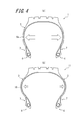
- FIG. 4 is a view showing the resultant force of air applied from the tire inner side to the tire width direction outer side on the tire inner surface during internal pressure filling.
- FIG. 4 (a) shows the case of the pneumatic tire of the present invention.
- b) shows the case of a conventional pneumatic tire.
- FIG. 5 is a sectional view in the tire width direction of the pneumatic tire of the present invention.
- FIG. 1 is a view showing a cross section in the tire width direction of a pneumatic tire 1 of the present invention (hereinafter referred to as “tire”) in a non-rim assembled state in which the rim is not assembled.
- the tire 1 includes a tread portion 2, a pair of sidewall portions 3 and 3, and a pair of bead portions 4 and 4. Further, a ply body 6a extending in a toroidal shape between a pair of bead cores 5 and 5 embedded in the bead parts 4 and 4, and a tire width direction around each bead core 5 and 5 extending from the ply body 6a.
- the carcass 6 is provided with at least one ply including a winding portion 6b wound from the inside to the outside.
- the tire 1 further has a recess 7 in the tire radial direction region from the rim separation point F to the tire maximum width position P 1 of the sidewall portion 3.
- the rim separation point F means that the outer surface of the tire is a rim flange when the tire 1 is assembled to the applicable rim, the normal maximum internal pressure defined according to the tire size is filled, and no load is applied. The point that leaves the contact state. Applicable rims are industrial standards effective in the area where tires are produced and used.
- the tire maximum width position P 1 of the sidewall portion 3 refers to the outermost end in the tire width direction in the sidewall portion 3.
- the outer surface of the tire in the tire radial direction area between the rim separation point F and the tire maximum width position P 1, is provided to include the whole, towards the inside of the tire width direction concave It is formed by removing the meat so that That is, the concave portion is formed by at least one arc having a center on the outer side in the width direction from the outer surface of the sidewall portion and protruding inward in the width direction when viewed from the center.
- the shape of the recess 7 is defined by combining a single circular arc or a plurality of circular arcs having a center C on the outer side in the tire width direction with respect to the side rubber constituting the sidewall portion 3 with respect to the side rubber.
- FIG. 2 is a view showing a half portion of the tire 1 shown in FIG.
- the shape of the recess 7 is defined by forming an arc of a circle R 1 having a center C 1 and a radius of curvature r 1 of 50 mm.
- FIG. 1 is a view showing a half portion of the tire 1 shown in FIG.
- the radius of curvature r 2 has a center C 2 is a circle R 2 is 30mm arc and the radius of curvature r 3 has a center C 3 is the arc of a circle R 3 is 400mm
- the shape of the recess 7 is defined by forming two arcs.
- the circle R 2 having the center C 2 is inscribed in the circle R 3 having the center C 3 , whereby the shape of the recess 7 is defined by combining the arcs of a plurality of circles. Has been.
- the rim separation point F and the recesses 7 defined by the circles R 1 and R 2 are separated from each other, that is, the rim separation point F and the circle R 1 or There is also an outer surface between R 2 (the outer surface exists between the rim separation point F and the innermost end 7a in the tire radial direction of the recess 7 described below) Although the surface is drawn so as to bend toward the inner side of the tire, the outer surface is not included in the recess 7 in the present invention.
- the range from the innermost point 7a in the tire radial direction of the recess 7 to the point 8 mm away from the outer periphery in the tire radial direction along the periphery of the recess 7 along the peripheral length 8mm is defined as the innermost region in the tire radial direction of the recess.
- the curve defining the innermost region in the tire radial direction of the recess 7 is approximated by an arc by the least square method, it is important that the radius of curvature r of the arc is 5 to 80 mm in the tire of the present invention. .
- the curvature radius r is less than 5 mm, the curvature becomes too large and the compressive stress generated by the deflection of the tire tends to concentrate, and the surface rubber wrinkles may cause cracks, If the curvature radius r exceeds 80 mm, the curvature is small and it is difficult to sufficiently roll the side rubber in the region from the rim separation point F to the tire maximum width position P 1 .
- the center of curvature C means the center C 1 of the circle R 1 in the example shown in FIG. 2 , and the center C 2 of the circle R 2 in the example shown in FIG. 3A.
- the weight of the tire can be reduced, but on the other hand, the lateral rigidity of the tire is reduced, and the steering stability is reduced. Accompanied by a decline. That is, since the rigidity from the bead portion to the sidewall portion is reduced by forming the concave portion 7, the tire shape is likely to change particularly when lateral force is applied, and as a result, the balance in the tire width direction is lost. As a result, steering stability is reduced.
- the present invention provides a pneumatic tire having a concave portion in the side rubber near the bead portion, and the elevation angle ⁇ of the intersection A formed by the straight line q connecting the two intersections A and B and the reference line n measured from the center of curvature C is 40.
- the angle By setting the angle to ⁇ 60 °, the lateral rigidity of the tire is improved and good steering stability is achieved.
- the carcass ply body 6a extending from the bead portion 4 to the sidewall portion 3 is more tire-like than the carcass ply body 16a in the conventional pneumatic tire 11 shown in FIG. 4 (b).
- the rising angle from the rotation axis is large, and the curvature of the carcass line from the bead portion to the sidewall portion is small. That is, when the tire 1 is filled with air, the ratio of the component of the internal pressure in the region from the bead portion to the sidewall portion toward the outer side in the tire width direction is larger than before, and the air in the tire moves the inner surface of the tire. Since the resultant force pushing outward in the tire width direction increases, the side rigidity of the tire increases. As a result, even if the recess 7 is provided in the side rubber, it is possible to suppress the falling deformation of the sidewall portion 3 of the tire 1 and to ensure good steering stability as a whole.
- the elevation angle ⁇ of the intersection A formed by the straight line q connecting the two intersections A and B with the reference line n is set to 40 ° to 60 °. in the smaller the curvature of the tire inside surface in the region up to the tire maximum width position P 1 of the wall portion 3, and sufficiently large force to press the region in the width direction outside from the inside of the tire, since it is possible to increase the side rigidity is there.
- the elevation angle ⁇ is more than 60 °, the bead portion may generate heat, which may affect the durability.
- the elevation angle is more than 60 °, it is necessary to increase the radius of curvature of the carcass near the belt end in order to ensure a cross-sectional shape that is effective in suppressing the collapse of the sidewall portion when filling with internal pressure. This is because the contact portion with the belt is only in the vicinity of the center of the tire, and separation of the portion may occur due to repeated input of lateral force.
- the carcass 6 is wound around the bead cores 5 and 5 from the inner side to the outer side in the tire width direction and has winding portions 6b and 6b.
- the starting position of the arc drawn by the center of curvature C can be brought closer to the rim separation point F, which greatly contributes to reducing the use of rubber and pulling the carcass 6. Omission can be made difficult.
- the elevation angle ⁇ at the intersection A where the straight line q forms the reference line n is more preferably 50 to 60 °.
- the tire width direction maximum width W 6 of the carcass 6 is 115-135% of the bead heel distance W 8 between the pair of bead heel 8,8, tire width direction outermost end of the carcass P 2 is a position in the tire radial direction closer to the outer side in the tire radial direction by 45% of the carcass height H from the innermost end P 3 in the tire radial direction of the carcass 6, and a carcass height from the innermost end P 3 in the tire radial direction in the carcass 6. It is preferable to be in the tire radial direction region S between 60% of the H and the tire radial direction position on the outer side in the tire radial direction.
- the tire width direction maximum width W 6 of the carcass 6, ply body 6a is that the tire width direction distance between tire width 6a direction outermost end P 2, P 2.
- the bead heel distance W8 is a distance in the tire width direction between the bead heels 8 and 8 of the pair of bead portions 4 and 4, and corresponds to the width of the applicable rim described in the standard such as JATMA. To do.
- FIG. 5 shows an example in which the carcass 6 is composed of a single ply, but the dimensions defined by the carcass are measured from the cord center of the carcass ply main body unless otherwise specified. .
- the above-mentioned definition is that the cord center line of the carcass ply main body portion on the innermost side in the tire width direction and the outermost side in the tire width direction are The dimension on the virtual carcass center line, which is a line passing through the center in the width direction with the cord center line of the ply main body portion of the carcass, is referred to.
- the flatness of the pneumatic tire 1 according to the present invention is preferably 60 to 80. Further, by assembling the tire to the application rim, in a state filled with maximum air pressure, the contour of the carcass 6a in the tire width direction outermost end P 2 is the radius of curvature r 4 is defined by an arc of 50 ⁇ 120 mm Is preferred.
- the thickness x of the sidewall portion 3 is constant.
- the thickness x of 3 is preferably 3.0 to 5.0 mm.
- the thickness x of the sidewall portion means the shortest distance from the cord center of the ply main body portion 6a in the sidewall portion 3 to the tire outer surface.
- the ratio of the component of the internal pressure toward the outer side in the tire width direction is larger than that of the conventional tire. Therefore, by setting the sidewall portion in the region S to have a constant thickness, it is possible to uniformly receive the outward force in the tire width direction, and as a result, better steering stability can be realized.
- the thickness x of the sidewall portion 3 in the region S is 3.0 to 5.0 mm in order to stably receive the force due to the internal pressure and in consideration of damage from the outside and a decrease in durability due to heat generation. It is preferable.
- the innermost end 7a in the tire radial direction of the recess 7 is in a tire radial region between a tire radial position at the rim separation point F and a tire radial position closer to the outer side in the tire radial direction by 10 mm from the rim separation point F. It is preferable that it exists in.
- the amount of rubber used around the bead can be sufficiently reduced, so that weight reduction can be achieved while maintaining appropriate tire rigidity. Because it can.
- the tire size is 275 / 80R22.5, and as shown in FIG. 1, the tire has a recess in the region from the rim separation point to the tire maximum width position, and the elevation angle at the intersection A is 40 to 60 °.
- Inventive tires 1 to 3 were prototyped. Each specification is as shown in Table 1.
- comparative tires 1 to 6 having a recess as in the invention example tire 1 and having the specifications shown in Table 1 were also prototyped.
- the tire weight reduction amount (kg) is a reduction amount from a tire having no recess, that is, the rubber weight (kg) of the recess.
- Each of the inventive tires 1 to 3 and the comparative tires 1 to 6 is assembled to a rim having a rim size of 8.25 ⁇ 22.5 and a rim width of 8.25 inches (21.0 cm), and the internal pressure is set to 900 kPa.
- the steering stability and durability were evaluated by performing the following tests.
- ⁇ Steering stability evaluation> This was performed by comprehensively evaluating the braking performance, acceleration performance, straight travel performance, and cornering performance of the test driver when the vehicle with the above tires was run on a test course in fine weather.
- the evaluation results are as shown in Table 2.
- the evaluation in Table 2 is expressed as an index with the result of Comparative Example Tire 1 being 100, and the larger the value, the better the steering stability.
- ⁇ Durability evaluation> A tire that has changed over time by being filled with oxygen in the tire (oxygen concentration of 90% or more) and assembled to a rim of the above size for 60 days in a thermostatic chamber at 60 ° C. was mounted on a drum testing machine.
- a drum tester having a diameter of 1.7 m with a slip angle of 110% (3575 kg) of the standard load by JATMA and a side force of 0.3 G (975 kg) at a test speed of 60 km / h.
- the results of the durability evaluation shown in Table 1 are expressed as an index by measuring the distance traveled until the cracks are generated and propagated from the recesses in the process of repeated rolling.
- the evaluation in Table 2 is based on the result of Comparative Example Tire 1 being 100, and the larger the value, the better the durability.
Landscapes
- Engineering & Computer Science (AREA)
- Mechanical Engineering (AREA)
- Tires In General (AREA)
Priority Applications (4)
| Application Number | Priority Date | Filing Date | Title |
|---|---|---|---|
| JP2013555199A JP5576994B2 (ja) | 2012-01-24 | 2013-01-23 | 空気入りタイヤ |
| EP13740906.6A EP2808183B1 (en) | 2012-01-24 | 2013-01-23 | Pneumatic tire |
| US14/372,305 US9120352B2 (en) | 2012-01-24 | 2013-01-23 | Pneumatic tire |
| CN201380006303.8A CN104066600B (zh) | 2012-01-24 | 2013-01-23 | 充气轮胎 |
Applications Claiming Priority (2)
| Application Number | Priority Date | Filing Date | Title |
|---|---|---|---|
| JP2012-012282 | 2012-01-24 | ||
| JP2012012282 | 2012-01-24 |
Publications (1)
| Publication Number | Publication Date |
|---|---|
| WO2013111576A1 true WO2013111576A1 (ja) | 2013-08-01 |
Family
ID=48873306
Family Applications (1)
| Application Number | Title | Priority Date | Filing Date |
|---|---|---|---|
| PCT/JP2013/000304 WO2013111576A1 (ja) | 2012-01-24 | 2013-01-23 | 空気入りタイヤ |
Country Status (5)
| Country | Link |
|---|---|
| US (1) | US9120352B2 (zh) |
| EP (1) | EP2808183B1 (zh) |
| JP (1) | JP5576994B2 (zh) |
| CN (1) | CN104066600B (zh) |
| WO (1) | WO2013111576A1 (zh) |
Cited By (5)
| Publication number | Priority date | Publication date | Assignee | Title |
|---|---|---|---|---|
| WO2015097925A1 (ja) * | 2013-12-27 | 2015-07-02 | 株式会社ブリヂストン | 空気入りタイヤ |
| WO2018163577A1 (ja) * | 2017-03-10 | 2018-09-13 | 横浜ゴム株式会社 | 空気入りタイヤ及びその製造方法 |
| CN115135515A (zh) * | 2020-02-19 | 2022-09-30 | 米其林集团总公司 | 具有低胎侧高度的轮胎 |
| EP4249288A1 (en) | 2022-03-23 | 2023-09-27 | Sumitomo Rubber Industries, Ltd. | Heavy duty tire and production method for heavy duty tire |
| WO2023188604A1 (ja) * | 2022-03-29 | 2023-10-05 | 横浜ゴム株式会社 | 空気入りタイヤ |
Families Citing this family (6)
| Publication number | Priority date | Publication date | Assignee | Title |
|---|---|---|---|---|
| JP6014114B2 (ja) * | 2012-03-02 | 2016-10-25 | 株式会社ブリヂストン | 空気入りタイヤ |
| CN104354540A (zh) * | 2014-10-13 | 2015-02-18 | 王友善 | 一种全钢丝三角胶外置的无内胎子午线轮胎 |
| JP6935365B2 (ja) * | 2018-06-21 | 2021-09-15 | 株式会社ブリヂストン | 建設車両用タイヤ |
| JP7081999B2 (ja) * | 2018-06-29 | 2022-06-07 | Toyo Tire株式会社 | 空気入りタイヤ |
| FR3096931B1 (fr) * | 2019-06-06 | 2021-05-21 | Michelin & Cie | Pneumatique comportant des flancs optimises et une armature de sommet constituee de deux couches de sommet de travail et d’une couche d’elements de renforcement circonferentiels |
| US20220153068A1 (en) | 2020-11-18 | 2022-05-19 | The Goodyear Tire & Rubber Company | Radial tire |
Citations (10)
| Publication number | Priority date | Publication date | Assignee | Title |
|---|---|---|---|---|
| JPS6061305A (ja) * | 1983-09-14 | 1985-04-09 | Bridgestone Corp | 転り抵抗の低い重荷重用空気入りタイヤ |
| JP2000016036A (ja) * | 1998-04-30 | 2000-01-18 | Bridgestone Corp | 空気入りラジアルタイヤ |
| JP2001225618A (ja) * | 2000-02-18 | 2001-08-21 | Bridgestone Corp | 空気入りラジアルタイヤ |
| JP2002521253A (ja) * | 1998-07-23 | 2002-07-16 | ソシエテ ド テクノロジー ミシュラン | ラジアルタイヤ用補強ビード |
| JP2003063217A (ja) * | 2001-08-29 | 2003-03-05 | Sumitomo Rubber Ind Ltd | 重荷重用チューブレスタイヤ |
| JP2003531057A (ja) * | 2000-04-25 | 2003-10-21 | ソシエテ ド テクノロジー ミシュラン | 小型化タイヤビード |
| JP2004535976A (ja) * | 2001-07-31 | 2004-12-02 | ソシエテ ド テクノロジー ミシュラン | 保護リブを備えたタイヤビード |
| WO2009051260A1 (ja) | 2007-10-19 | 2009-04-23 | Bridgestone Corporation | 空気入りタイヤ |
| JP2010111370A (ja) * | 2008-10-09 | 2010-05-20 | Bridgestone Corp | 空気入りタイヤ |
| JP2011088565A (ja) * | 2009-10-23 | 2011-05-06 | Bridgestone Corp | 空気入りタイヤ |
Family Cites Families (13)
| Publication number | Priority date | Publication date | Assignee | Title |
|---|---|---|---|---|
| US4693290A (en) * | 1977-03-01 | 1987-09-15 | The Goodyear & Rubber Company | Bias ply snow tire compatible with radial ply tires |
| US4345634A (en) * | 1980-06-04 | 1982-08-24 | Michelin Recherche Et Technique S.A. | Tire for medium and heavy carrier vehicles |
| JP3643191B2 (ja) * | 1995-11-29 | 2005-04-27 | 株式会社ブリヂストン | トラック及びバス用15°テーパラジアルタイヤ |
| JP2744427B2 (ja) * | 1986-12-25 | 1998-04-28 | 株式会社ブリヂストン | トラック及びバス用空気入りラジアルタイヤ |
| JP2574816B2 (ja) * | 1987-10-27 | 1997-01-22 | 住友ゴム工業 株式会社 | 安全タイヤ |
| DE69301385T2 (de) * | 1992-07-23 | 1996-05-30 | Sumitomo Rubber Ind | Radialer Luftreifen |
| ID20252A (id) * | 1997-01-09 | 1998-11-12 | Sumitomo Rubber Ind | Ban pneumatik |
| JP4548776B2 (ja) * | 2004-10-25 | 2010-09-22 | 株式会社ブリヂストン | 重荷重用空気入りラジアルタイヤ |
| JP2006218936A (ja) * | 2005-02-09 | 2006-08-24 | Bridgestone Corp | 重荷重用空気入りラジアルタイヤ |
| JP4801702B2 (ja) * | 2008-07-31 | 2011-10-26 | 住友ゴム工業株式会社 | 空気入りタイヤ |
| JP2011079469A (ja) * | 2009-10-08 | 2011-04-21 | Bridgestone Corp | 空気入りタイヤ |
| JP5883208B2 (ja) * | 2009-10-14 | 2016-03-09 | 株式会社ブリヂストン | 空気入りタイヤ |
| JP2011152824A (ja) * | 2010-01-26 | 2011-08-11 | Bridgestone Corp | タイヤ |
-
2013
- 2013-01-23 EP EP13740906.6A patent/EP2808183B1/en not_active Not-in-force
- 2013-01-23 CN CN201380006303.8A patent/CN104066600B/zh not_active Expired - Fee Related
- 2013-01-23 US US14/372,305 patent/US9120352B2/en not_active Expired - Fee Related
- 2013-01-23 JP JP2013555199A patent/JP5576994B2/ja not_active Expired - Fee Related
- 2013-01-23 WO PCT/JP2013/000304 patent/WO2013111576A1/ja active Application Filing
Patent Citations (10)
| Publication number | Priority date | Publication date | Assignee | Title |
|---|---|---|---|---|
| JPS6061305A (ja) * | 1983-09-14 | 1985-04-09 | Bridgestone Corp | 転り抵抗の低い重荷重用空気入りタイヤ |
| JP2000016036A (ja) * | 1998-04-30 | 2000-01-18 | Bridgestone Corp | 空気入りラジアルタイヤ |
| JP2002521253A (ja) * | 1998-07-23 | 2002-07-16 | ソシエテ ド テクノロジー ミシュラン | ラジアルタイヤ用補強ビード |
| JP2001225618A (ja) * | 2000-02-18 | 2001-08-21 | Bridgestone Corp | 空気入りラジアルタイヤ |
| JP2003531057A (ja) * | 2000-04-25 | 2003-10-21 | ソシエテ ド テクノロジー ミシュラン | 小型化タイヤビード |
| JP2004535976A (ja) * | 2001-07-31 | 2004-12-02 | ソシエテ ド テクノロジー ミシュラン | 保護リブを備えたタイヤビード |
| JP2003063217A (ja) * | 2001-08-29 | 2003-03-05 | Sumitomo Rubber Ind Ltd | 重荷重用チューブレスタイヤ |
| WO2009051260A1 (ja) | 2007-10-19 | 2009-04-23 | Bridgestone Corporation | 空気入りタイヤ |
| JP2010111370A (ja) * | 2008-10-09 | 2010-05-20 | Bridgestone Corp | 空気入りタイヤ |
| JP2011088565A (ja) * | 2009-10-23 | 2011-05-06 | Bridgestone Corp | 空気入りタイヤ |
Non-Patent Citations (1)
| Title |
|---|
| See also references of EP2808183A4 * |
Cited By (11)
| Publication number | Priority date | Publication date | Assignee | Title |
|---|---|---|---|---|
| WO2015097925A1 (ja) * | 2013-12-27 | 2015-07-02 | 株式会社ブリヂストン | 空気入りタイヤ |
| CN105829129A (zh) * | 2013-12-27 | 2016-08-03 | 株式会社普利司通 | 充气轮胎 |
| EP3088210A4 (en) * | 2013-12-27 | 2017-01-11 | Bridgestone Corporation | Pneumatic tire |
| US9902211B2 (en) | 2013-12-27 | 2018-02-27 | Bridgestone Corporation | Pneumatic tire |
| WO2018163577A1 (ja) * | 2017-03-10 | 2018-09-13 | 横浜ゴム株式会社 | 空気入りタイヤ及びその製造方法 |
| JP2018149835A (ja) * | 2017-03-10 | 2018-09-27 | 横浜ゴム株式会社 | 空気入りタイヤ及びその製造方法 |
| US11400757B2 (en) | 2017-03-10 | 2022-08-02 | The Yokohama Rubber Co., Ltd. | Pneumatic tire and method for manufacturing same |
| CN115135515A (zh) * | 2020-02-19 | 2022-09-30 | 米其林集团总公司 | 具有低胎侧高度的轮胎 |
| CN115135515B (zh) * | 2020-02-19 | 2023-09-19 | 米其林集团总公司 | 具有低胎侧高度的轮胎 |
| EP4249288A1 (en) | 2022-03-23 | 2023-09-27 | Sumitomo Rubber Industries, Ltd. | Heavy duty tire and production method for heavy duty tire |
| WO2023188604A1 (ja) * | 2022-03-29 | 2023-10-05 | 横浜ゴム株式会社 | 空気入りタイヤ |
Also Published As
| Publication number | Publication date |
|---|---|
| US9120352B2 (en) | 2015-09-01 |
| US20140345770A1 (en) | 2014-11-27 |
| EP2808183B1 (en) | 2016-11-16 |
| EP2808183A1 (en) | 2014-12-03 |
| JPWO2013111576A1 (ja) | 2015-05-11 |
| CN104066600A (zh) | 2014-09-24 |
| JP5576994B2 (ja) | 2014-08-20 |
| EP2808183A4 (en) | 2015-08-26 |
| CN104066600B (zh) | 2016-09-14 |
Similar Documents
| Publication | Publication Date | Title |
|---|---|---|
| JP5576994B2 (ja) | 空気入りタイヤ | |
| JP6014114B2 (ja) | 空気入りタイヤ | |
| JP5030978B2 (ja) | 空気入りタイヤ | |
| JP5750156B2 (ja) | 空気入りタイヤ | |
| JP6393690B2 (ja) | タイヤ | |
| JP6342669B2 (ja) | 空気入りタイヤ | |
| JP5771681B2 (ja) | 空気入りタイヤ | |
| JP5845710B2 (ja) | 空気入りタイヤ | |
| JP2018070110A (ja) | 空気入りタイヤ | |
| JP6710995B2 (ja) | 空気入りタイヤ | |
| JP2009083769A (ja) | 空気入りタイヤ | |
| JP5868040B2 (ja) | 二輪自動車用タイヤ | |
| JP2016068834A (ja) | 空気入りタイヤ | |
| JP6315667B2 (ja) | 空気入りタイヤ | |
| JP6291430B2 (ja) | スタッドレスタイヤ | |
| JP5823795B2 (ja) | 重荷重用空気入りラジアルタイヤ | |
| JP6077944B2 (ja) | 空気入りタイヤ | |
| JP6075954B2 (ja) | 空気入りラジアルタイヤ | |
| JP5141414B2 (ja) | 空気入りタイヤ対 | |
| JP2011207319A (ja) | 空気入りタイヤ | |
| JP2010274769A (ja) | ランフラットタイヤ | |
| JP2016210275A (ja) | 空気入りタイヤ | |
| JP2017074828A (ja) | 空気入りタイヤ |
Legal Events
| Date | Code | Title | Description |
|---|---|---|---|
| 121 | Ep: the epo has been informed by wipo that ep was designated in this application |
Ref document number: 13740906 Country of ref document: EP Kind code of ref document: A1 |
|
| ENP | Entry into the national phase |
Ref document number: 2013555199 Country of ref document: JP Kind code of ref document: A |
|
| WWE | Wipo information: entry into national phase |
Ref document number: 14372305 Country of ref document: US |
|
| NENP | Non-entry into the national phase |
Ref country code: DE |
|
| REEP | Request for entry into the european phase |
Ref document number: 2013740906 Country of ref document: EP |
|
| WWE | Wipo information: entry into national phase |
Ref document number: 2013740906 Country of ref document: EP |