WO2013081075A1 - 組み合わせシールリング付転がり軸受ユニット - Google Patents
組み合わせシールリング付転がり軸受ユニット Download PDFInfo
- Publication number
- WO2013081075A1 WO2013081075A1 PCT/JP2012/080992 JP2012080992W WO2013081075A1 WO 2013081075 A1 WO2013081075 A1 WO 2013081075A1 JP 2012080992 W JP2012080992 W JP 2012080992W WO 2013081075 A1 WO2013081075 A1 WO 2013081075A1
- Authority
- WO
- WIPO (PCT)
- Prior art keywords
- ring
- seal lip
- stationary
- seal
- rolling bearing
- Prior art date
Links
Images


Classifications
-
- F—MECHANICAL ENGINEERING; LIGHTING; HEATING; WEAPONS; BLASTING
- F16—ENGINEERING ELEMENTS AND UNITS; GENERAL MEASURES FOR PRODUCING AND MAINTAINING EFFECTIVE FUNCTIONING OF MACHINES OR INSTALLATIONS; THERMAL INSULATION IN GENERAL
- F16C—SHAFTS; FLEXIBLE SHAFTS; ELEMENTS OR CRANKSHAFT MECHANISMS; ROTARY BODIES OTHER THAN GEARING ELEMENTS; BEARINGS
- F16C33/00—Parts of bearings; Special methods for making bearings or parts thereof
- F16C33/72—Sealings
- F16C33/76—Sealings of ball or roller bearings
- F16C33/80—Labyrinth sealings
- F16C33/805—Labyrinth sealings in addition to other sealings, e.g. dirt guards to protect sealings with sealing lips
-
- F—MECHANICAL ENGINEERING; LIGHTING; HEATING; WEAPONS; BLASTING
- F16—ENGINEERING ELEMENTS AND UNITS; GENERAL MEASURES FOR PRODUCING AND MAINTAINING EFFECTIVE FUNCTIONING OF MACHINES OR INSTALLATIONS; THERMAL INSULATION IN GENERAL
- F16C—SHAFTS; FLEXIBLE SHAFTS; ELEMENTS OR CRANKSHAFT MECHANISMS; ROTARY BODIES OTHER THAN GEARING ELEMENTS; BEARINGS
- F16C33/00—Parts of bearings; Special methods for making bearings or parts thereof
- F16C33/72—Sealings
- F16C33/76—Sealings of ball or roller bearings
- F16C33/768—Sealings of ball or roller bearings between relatively stationary parts, i.e. static seals
-
- F—MECHANICAL ENGINEERING; LIGHTING; HEATING; WEAPONS; BLASTING
- F16—ENGINEERING ELEMENTS AND UNITS; GENERAL MEASURES FOR PRODUCING AND MAINTAINING EFFECTIVE FUNCTIONING OF MACHINES OR INSTALLATIONS; THERMAL INSULATION IN GENERAL
- F16C—SHAFTS; FLEXIBLE SHAFTS; ELEMENTS OR CRANKSHAFT MECHANISMS; ROTARY BODIES OTHER THAN GEARING ELEMENTS; BEARINGS
- F16C33/00—Parts of bearings; Special methods for making bearings or parts thereof
- F16C33/72—Sealings
- F16C33/76—Sealings of ball or roller bearings
- F16C33/78—Sealings of ball or roller bearings with a diaphragm, disc, or ring, with or without resilient members
- F16C33/7816—Details of the sealing or parts thereof, e.g. geometry, material
- F16C33/782—Details of the sealing or parts thereof, e.g. geometry, material of the sealing region
- F16C33/7823—Details of the sealing or parts thereof, e.g. geometry, material of the sealing region of sealing lips
-
- F—MECHANICAL ENGINEERING; LIGHTING; HEATING; WEAPONS; BLASTING
- F16—ENGINEERING ELEMENTS AND UNITS; GENERAL MEASURES FOR PRODUCING AND MAINTAINING EFFECTIVE FUNCTIONING OF MACHINES OR INSTALLATIONS; THERMAL INSULATION IN GENERAL
- F16C—SHAFTS; FLEXIBLE SHAFTS; ELEMENTS OR CRANKSHAFT MECHANISMS; ROTARY BODIES OTHER THAN GEARING ELEMENTS; BEARINGS
- F16C33/00—Parts of bearings; Special methods for making bearings or parts thereof
- F16C33/72—Sealings
- F16C33/76—Sealings of ball or roller bearings
- F16C33/78—Sealings of ball or roller bearings with a diaphragm, disc, or ring, with or without resilient members
- F16C33/7869—Sealings of ball or roller bearings with a diaphragm, disc, or ring, with or without resilient members mounted with a cylindrical portion to the inner surface of the outer race and having a radial portion extending inward
- F16C33/7879—Sealings of ball or roller bearings with a diaphragm, disc, or ring, with or without resilient members mounted with a cylindrical portion to the inner surface of the outer race and having a radial portion extending inward with a further sealing ring
- F16C33/7883—Sealings of ball or roller bearings with a diaphragm, disc, or ring, with or without resilient members mounted with a cylindrical portion to the inner surface of the outer race and having a radial portion extending inward with a further sealing ring mounted to the inner race and of generally L-shape, the two sealing rings defining a sealing with box-shaped cross-section
-
- F—MECHANICAL ENGINEERING; LIGHTING; HEATING; WEAPONS; BLASTING
- F16—ENGINEERING ELEMENTS AND UNITS; GENERAL MEASURES FOR PRODUCING AND MAINTAINING EFFECTIVE FUNCTIONING OF MACHINES OR INSTALLATIONS; THERMAL INSULATION IN GENERAL
- F16C—SHAFTS; FLEXIBLE SHAFTS; ELEMENTS OR CRANKSHAFT MECHANISMS; ROTARY BODIES OTHER THAN GEARING ELEMENTS; BEARINGS
- F16C41/00—Other accessories, e.g. devices integrated in the bearing not relating to the bearing function as such
- F16C41/007—Encoders, e.g. parts with a plurality of alternating magnetic poles
-
- F—MECHANICAL ENGINEERING; LIGHTING; HEATING; WEAPONS; BLASTING
- F16—ENGINEERING ELEMENTS AND UNITS; GENERAL MEASURES FOR PRODUCING AND MAINTAINING EFFECTIVE FUNCTIONING OF MACHINES OR INSTALLATIONS; THERMAL INSULATION IN GENERAL
- F16J—PISTONS; CYLINDERS; SEALINGS
- F16J15/00—Sealings
- F16J15/16—Sealings between relatively-moving surfaces
- F16J15/32—Sealings between relatively-moving surfaces with elastic sealings, e.g. O-rings
- F16J15/3248—Sealings between relatively-moving surfaces with elastic sealings, e.g. O-rings provided with casings or supports
- F16J15/3252—Sealings between relatively-moving surfaces with elastic sealings, e.g. O-rings provided with casings or supports with rigid casings or supports
- F16J15/3256—Sealings between relatively-moving surfaces with elastic sealings, e.g. O-rings provided with casings or supports with rigid casings or supports comprising two casing or support elements, one attached to each surface, e.g. cartridge or cassette seals
- F16J15/3264—Sealings between relatively-moving surfaces with elastic sealings, e.g. O-rings provided with casings or supports with rigid casings or supports comprising two casing or support elements, one attached to each surface, e.g. cartridge or cassette seals the elements being separable from each other
-
- G—PHYSICS
- G01—MEASURING; TESTING
- G01P—MEASURING LINEAR OR ANGULAR SPEED, ACCELERATION, DECELERATION, OR SHOCK; INDICATING PRESENCE, ABSENCE, OR DIRECTION, OF MOVEMENT
- G01P3/00—Measuring linear or angular speed; Measuring differences of linear or angular speeds
- G01P3/42—Devices characterised by the use of electric or magnetic means
- G01P3/44—Devices characterised by the use of electric or magnetic means for measuring angular speed
- G01P3/443—Devices characterised by the use of electric or magnetic means for measuring angular speed mounted in bearings
-
- F—MECHANICAL ENGINEERING; LIGHTING; HEATING; WEAPONS; BLASTING
- F16—ENGINEERING ELEMENTS AND UNITS; GENERAL MEASURES FOR PRODUCING AND MAINTAINING EFFECTIVE FUNCTIONING OF MACHINES OR INSTALLATIONS; THERMAL INSULATION IN GENERAL
- F16C—SHAFTS; FLEXIBLE SHAFTS; ELEMENTS OR CRANKSHAFT MECHANISMS; ROTARY BODIES OTHER THAN GEARING ELEMENTS; BEARINGS
- F16C19/00—Bearings with rolling contact, for exclusively rotary movement
- F16C19/02—Bearings with rolling contact, for exclusively rotary movement with bearing balls essentially of the same size in one or more circular rows
- F16C19/14—Bearings with rolling contact, for exclusively rotary movement with bearing balls essentially of the same size in one or more circular rows for both radial and axial load
- F16C19/18—Bearings with rolling contact, for exclusively rotary movement with bearing balls essentially of the same size in one or more circular rows for both radial and axial load with two or more rows of balls
- F16C19/181—Bearings with rolling contact, for exclusively rotary movement with bearing balls essentially of the same size in one or more circular rows for both radial and axial load with two or more rows of balls with angular contact
- F16C19/183—Bearings with rolling contact, for exclusively rotary movement with bearing balls essentially of the same size in one or more circular rows for both radial and axial load with two or more rows of balls with angular contact with two rows at opposite angles
- F16C19/184—Bearings with rolling contact, for exclusively rotary movement with bearing balls essentially of the same size in one or more circular rows for both radial and axial load with two or more rows of balls with angular contact with two rows at opposite angles in O-arrangement
- F16C19/186—Bearings with rolling contact, for exclusively rotary movement with bearing balls essentially of the same size in one or more circular rows for both radial and axial load with two or more rows of balls with angular contact with two rows at opposite angles in O-arrangement with three raceways provided integrally on parts other than race rings, e.g. third generation hubs
-
- F—MECHANICAL ENGINEERING; LIGHTING; HEATING; WEAPONS; BLASTING
- F16—ENGINEERING ELEMENTS AND UNITS; GENERAL MEASURES FOR PRODUCING AND MAINTAINING EFFECTIVE FUNCTIONING OF MACHINES OR INSTALLATIONS; THERMAL INSULATION IN GENERAL
- F16C—SHAFTS; FLEXIBLE SHAFTS; ELEMENTS OR CRANKSHAFT MECHANISMS; ROTARY BODIES OTHER THAN GEARING ELEMENTS; BEARINGS
- F16C2326/00—Articles relating to transporting
- F16C2326/01—Parts of vehicles in general
- F16C2326/02—Wheel hubs or castors
Definitions
- the present invention exists, for example, in a rolling bearing unit for rotatably supporting a wheel of an automobile with respect to a suspension device, between circumferential surfaces facing each other of a rotation side raceway and a stationary side raceway.
- the present invention relates to an improvement of a rolling bearing unit with a combined seal ring in which an end opening of a bearing internal space in which a plurality of rolling elements are installed is closed with a combined seal ring including a slinger and a seal ring.
- a structure capable of maintaining the sealing performance of the combined seal ring well over a long period of time by suppressing the amount of foreign matter that enters the seal internal space existing between the slinger and the seal ring. Is to be realized.
- Patent Document 1 describes a structure of a wheel supporting rolling bearing unit as shown in FIG.
- an outer ring 2 that is a stationary side race ring and a hub 3 that is a rotation side race ring are arranged concentrically with each other.
- the double row outer ring raceways 4 and 4 each provided on the inner peripheral surface of the outer ring 2 are stationary side raceways, and the double row each provided on the outer peripheral surface of the hub 3 and each is a rotary side raceway.
- a plurality of balls 6 and 6 each of which is a rolling element are arranged in each row.
- the hub 3 is rotatably supported on the inner diameter side of the outer ring 2.
- a stationary side flange 8 provided on the outer peripheral surface of the outer ring 2 is screwed to the suspension device and the outer end of the hub 3 in the axial direction is fixed.
- Part (outside with respect to the axial direction) means the left side of each figure, which is the outer side in the width direction of this vehicle in the assembled state to the vehicle. In the axial direction, the inside is referred to.)
- the rotating body for braking such as the wheel and the disk rotor is screwed and fixed to the rotation side flange 9 formed on the outer peripheral surface.
- Both end openings of the bearing internal space 10 in which the balls 6, 6 are installed between the inner peripheral surface of the outer ring 2 and the outer peripheral surface of the hub 3 are surrounded by a seal ring 11 and a combination seal ring 12, respectively. It is crawling on and blocking.
- the seal ring 11 that closes the axially outer end side opening of the bearing internal space 10 reinforces an elastic material 14 made of an elastomer such as rubber with a metal core 13 made of a metal plate, and the whole is formed in an annular shape. Consists of.
- the elastic member 14 has a plurality of (three in the illustrated example) seal lips 15a, 15b, and 15c.
- the combination seal ring 12 is formed by combining a slinger 16 and a seal ring 17.
- the slinger 16 is formed by bending a metal plate to form an annular shape as a whole with an L-shaped cross section.
- the slinger 16 has a diameter from the rotation-side cylindrical portion 18 and the inner edge in the axial direction of the rotation-side cylindrical portion 18. It consists of a rotation-side annular ring portion 19 bent outward in the direction.
- Such a slinger 16 is fitted to the hub 3 by fitting the rotating cylindrical portion 18 to the inner end of the hub 3 (inner ring constituting the hub 3 together with the hub body) by an interference fit. It is fixed.
- the seal ring 17 includes a metal core 20 and an elastic member 21.
- the elastic material 21 includes a plurality of (three in the illustrated example) seal lips 22a, 22b, and 22c.
- the metal core 20 is formed by bending a metal plate to form an annular shape as a whole with an L-shaped cross section. From the stationary side cylindrical portion 23 and the axially outer end edge of the stationary side cylindrical portion 23. The stationary side annular portion 24 is bent inward in the radial direction.
- the seal ring 17 having such a cored bar 20 is fixed to the outer ring 2 by fitting the stationary-side cylindrical part 23 into the inner end of the outer ring 2 in the axial direction by an interference fit.
- the front end edge of the seal lip 22a is on the outer side surface in the axial direction of the rotary side annular portion 19, and the front end edge of each of the seal lips 22b and 22c is on the outer peripheral surface of the rotary side cylindrical portion 18. Each is in contact with the entire circumference.
- the annular encoder 25 may be attached and fixed over the entire circumference.
- the encoder 25 is made of a permanent magnet such as a rubber magnet or a plastic magnet in which a magnetic powder is dispersed in a polymer material such as rubber or synthetic resin to form a ring shape as a whole, and is magnetized in the axial direction. The magnetization direction is changed alternately and at equal intervals in the circumferential direction.
- the south pole and the north pole are alternately arranged at equal intervals in the circumferential direction on the inner side surface in the axial direction of the encoder 25, which is the detected surface.
- the detection surface of the rotation detection sensor (not shown) is opposed to the detection surface of such an encoder 25 so that the rotation speed of the wheel rotating together with the hub 3 can be measured.
- the measured signal representing the rotational speed of the wheel is used to control a vehicle travel stabilization device such as an anti-lock brake system (ABS) or a traction control system (TCS).
- ABS anti-lock brake system
- TCS traction control system
- the slinger 16 is not provided with an encoder as shown in FIG. 19B.
- leakage of grease existing in the bearing internal space 10 can be achieved by closing both axial ends of the bearing internal space 10 over the entire circumference with the seal ring 11 and the combination seal ring 12. It is intended to prevent the foreign matter such as moisture and dust existing in the external space from entering the bearing internal space 10.
- the seal ring 11 and the combination seal ring 12 are used under severe conditions where muddy water or the like is applied during use.
- the water of the muddy water that has entered the seal internal space 26 surrounded by the slinger 16 and the seal ring 17 evaporates, and only the solid content (mud) is this.
- the solid content mud
- the seal inner space 26 is located in the radially outer portion further than the seal lip 22a that is present on the outermost diameter side, and is interposed via the labyrinth seal 27. Since the volume of the external space 28 communicating with the external space is large, the amount of solid content accumulated in the external space 28 tends to increase. Then, the solid content accumulated in the outer space 28 may also adhere to the seal lip 22a existing on the outermost diameter side, and the movement of the seal lip 22a may be hindered.
- the gap dimension (width dimension in the radial direction) of the labyrinth seal 27 is reduced, foreign matter such as muddy water entering the outer space 28 can be reduced, but there is a limit to reducing this gap dimension. That is, if the gap dimension of the labyrinth seal 27 is extremely small, the outer ring 2 and the hub 3 are relatively inclined due to a moment load applied when the vehicle is turning and the distance between the labyrinth seal 27 is shortened and the rotation There is a possibility that the edge of the side circular ring part 19 and the inner peripheral surface of the stationary side cylindrical part 23 come into violent (strong) contact. Therefore, in the conventional structure shown in FIGS. 18, 19A, and 19B, it is difficult to extremely reduce the gap dimension of the labyrinth seal 27.
- Patent Document 2 discloses that the tip end edge of the second seal lip constituting the second seal ring fitted on the outer ring is connected to the rotation-side annular portion of the slinger.
- a structure is described in which the entire surface is in sliding contact with the side surface opposite to the seal ring. According to such a structure, it is possible to sufficiently prevent foreign matter from entering the seal internal space, but the number of parts increases and the cost increases.
- the installation space for the portion where the second seal ring is provided increases, and the degree of freedom in design may be limited to prevent interference with other articles provided adjacent to the rolling bearing unit with the combined seal ring. There is.
- the present invention provides a slinger that forms a combined seal ring that closes an end opening of a bearing internal space that exists between both stationary and rotating bearing rings that constitute a rolling bearing unit.
- a structure that can prevent the intrusion of foreign matter into the seal internal space between the seal ring and the seal lip provided on the seal ring can be secured to maintain excellent sealing performance over a long period of time.
- the rolling bearing unit with a combination seal ring of the present invention includes a rotation side race ring and a stationary side race ring, a plurality of rolling elements, and a combination seal ring.
- the rotation-side raceway and the stationary-side raceway rotate relative to each other while being concentrically arranged.
- Each of the rolling elements is provided so as to be able to roll between a rotation side track and a stationary side track, which are provided on circumferential surfaces facing each other of the rotation side raceway and the stationary side raceway.
- the combination seal ring closes an end opening of a bearing internal space existing between the mutually facing peripheral surfaces of the rotating side raceway and the stationary side raceway, and includes a slinger and a seal ring. .
- the slinger is fitted and fixed to a part of the peripheral surface of the rotating raceway facing the peripheral surface of the stationary raceway, and has a L-shaped cross section by bending a metal plate.
- the rotation side cylindrical portion and a rotation side circular ring portion bent in the radial direction from the axial end edge of the rotation side cylindrical portion toward the stationary ring raceway.
- the rotation side cylindrical part is being fixed to this rotation side bearing ring by fitting to the surrounding surface of the rotation side bearing ring.
- the seal ring is a part of the stationary side race ring that is fitted and fixed to a portion facing the slinger, and a cored bar that is fitted and fixed to the stationary side raceway ring.
- the metal core is formed by bending a metal plate to form an annular shape as a whole with an L-shaped cross section. From the stationary side cylindrical portion and the axial end edge of the stationary side cylindrical portion, the rotating side track And a stationary-side circular ring portion that is bent in the radial direction toward the ring. Then, the stationary side cylindrical portion is fixed to the stationary side raceway by fitting it to the peripheral surface of the stationary side raceway, and the tip of each seal lip is placed on the surface of the slinger on the entire circumference. It is in contact with slid. Furthermore, a labyrinth seal is provided between the tip side peripheral edge (periphery of the radial side opposite to the rotary side cylindrical part) and the peripheral surface of the stationary side cylindrical part.
- At least a part of the seal lips at the base of the elastic material is closer to the stationary cylindrical part than the seal lips.
- An auxiliary seal lip having a lower rigidity than a seal lip closer to the outer space, which is the seal lip closest to the labyrinth seal, is provided integrally with the elastic material.
- the tip edge of the auxiliary seal lip is slidably contacted or closely opposed over the entire circumference on the side surface in the axial direction of the rotating-side annular ring portion.
- a peripheral surface of the stationary side cylindrical portion on the side where the stationary side annular portion is provided is covered with the elastic material.
- the inner and outer peripheral edges of the portion of the elastic material that covers the side surface in the axial direction of the stationary ring portion, the portion that covers the peripheral surface, and the base of the auxiliary seal lip are divided into quarters. Smoothly continuous with a single circular arc-shaped curved surface.
- the seal ring and the slinger are combined, and the tip of the outer space-side seal lip is elastically brought into contact with the axial side surface of the rotating-side annular ring portion.
- the leading edge is brought close to and opposed to one peripheral surface of the auxiliary seal lip.
- the degree of proximity facing is set such that the auxiliary seal lip does not reverse in the radial direction (does not turn in the radial direction) by the fluid that enters through the labyrinth seal and presses the other peripheral surface of the auxiliary seal lip.
- the radial one side and the axial one side are partitioned by the peripheral surface of the stationary cylindrical portion and the axial side surface of the stationary annular portion, in the radial direction and the axial direction.
- a thick portion having a thickness dimension larger than that of other portions is provided.
- assistant seal lip is made to continue in the part near said each seal lip regarding radial direction among the axial direction end surfaces of this thick part.
- the recessed part which each opens in the axial direction end surface of this thick part in the circumferential direction several places of the radial direction intermediate part of the said thick part is formed.
- assistant seal lip is located in a part near each said seal lip rather than these each recessed part among the axial direction end surfaces of this thick part.
- the stationary side annular portion is radiated from the proximal end side annular portion closest to the stationary side cylindrical portion with respect to the radial direction and the distal end side peripheral edge of the proximal end annular portion.
- a conical inclined portion that is inclined in a direction away from the rotation-side annular portion toward the distal end side in the direction, and the proximal-side circle that is continuous in the radial direction from the peripheral edge on the distal end side of the inclined portion.
- a stepped shape having a ring portion and a front end side circular ring portion is provided. And the base end part of the said auxiliary seal lip is located in the front end side part of the said base end side annular ring part.
- a ridge that protrudes in the axial direction toward the rotation-side annular portion is formed on the entire circumference of the stationary-side annular portion in the radial direction.
- the base end part of the said auxiliary seal lip is located in the front-end
- the distal end portion of the rotating-side annular portion is formed by bending a portion near the distal end in the radial direction of the rotating-side annular portion over the entire circumference with respect to the thickness direction of the rotating-side annular portion. It is positioned closer to the stationary-side annular part than the intermediate part or the base end part. Then, the front end edge of the auxiliary seal lip is slidably contacted or closely opposed to the axial side surface of the front end portion of the rotating side annular ring portion over the entire circumference.
- a part of the elastic material is provided in a state of covering the peripheral surface on the opposite side to the stationary side raceway among the inner and outer peripheral surfaces of the stationary side cylindrical portion.
- the diameter of the rotating side annular part is opposite to the stationary side annular part across the tip of the rotating side annular part, and the diameter from this part toward the rotating side cylindrical part
- the locking lip protruding in the direction is intermittently provided in the circumferential direction. Furthermore, the front end portion of the locking lip and the front end portion of the rotation-side annular ring portion are overlapped with each other in the axial direction. Then, separation of the slinger and the seal ring is prevented.
- the rotating side bearing ring is an inner diameter side bearing ring existing radially inward
- the stationary side bearing ring is an outer diameter side bearing ring existing radially outward
- the auxiliary seal lip has a shape inclined in a direction in which the diameter increases toward the tip edge. Then, the front end edge of the auxiliary seal lip is closely opposed to the axial side surface of the rotation-side annular portion over the entire circumference in a non-contact state, and the front-end edge of the auxiliary seal lip and the rotation-side annular portion are A labyrinth seal is provided around the entire circumference between the axial side surfaces.
- the shape of at least an intermediate part or a tip edge part of the auxiliary seal lip is a partially conical cylinder.
- the auxiliary seal lip has a circular arc shape whose outer peripheral surface is a concave surface.
- tip parts of this auxiliary seal lip is made parallel to this axial direction side surface.
- the auxiliary seal lip is composed of a partially conical cylindrical intermediate portion and an annular flange that is bent radially outward from the leading edge of the intermediate portion. And this collar part and the axial direction side surface of the said rotation side annular ring part are made to adjoin and oppose over the perimeter.
- the tip edge of the auxiliary seal lip is brought into sliding contact with the side surface in the axial direction of the rotation-side annular ring portion.
- a shape in the circumferential direction of at least a portion slidably in contact with the side surface in the axial direction in the tip edge is an uneven shape.
- the tip edge is intermittently brought into sliding contact with the side surface in the axial direction in the circumferential direction.
- a magnetic powder in a polymer material is formed on a surface opposite to the surface facing the stationary side annular portion among the axially opposite side surfaces of the rotating side annular portion.
- a permanent magnet encoder having a ring shape as a whole is dispersed.
- the labyrinth seal is provided in the said part by making the periphery of this encoder oppose the surrounding surface of the said stationary side cylindrical part.
- a part of the polymer material constituting the encoder causes the entire circumference toward the stationary side annular part side beyond the distal end side peripheral part of the rotating side annular part. Protruding ridges are formed.
- the rotation side raceway is an inner diameter side raceway existing radially inward
- the stationary side raceway is an outer diameter side raceway existing radially outward
- the part with the largest outer diameter among the outer peripheral surfaces of the encoder is present on the opposite side with respect to the rotating-side annular portion with respect to the axial direction with the locking lip interposed therebetween.
- a portion having the largest outer diameter among the encoders is provided in a portion closer to the inner side in the axial direction in an intermediate portion in the axial direction of the outer peripheral surface of the encoder.
- the seal inner space existing between the slinger and the seal ring constituting the combined seal ring is adjacent to the seal lip closer to the external space. Intrusion of foreign matter such as muddy water into the portion (external space 28 shown in FIGS. 18, 19A and 19B) can be effectively prevented. That is, in the case of the rolling bearing unit with a combined seal ring according to the present invention, the outer side space communicating with the outer space via the labyrinth seal is divided into two in the radial direction by the auxiliary seal lip. Then, the auxiliary seal lip exists between the seal lip closer to the outer space and the labyrinth seal.
- the amount of foreign matter such as muddy water reaching the outer space-side seal lip is reduced, and a large amount of solid matter adheres to the outer space-side seal lip, thereby impairing the movement of the outer space-side seal lip. Can be prevented.
- good sealing performance can be exhibited over a long period of time, and the durability of the rolling bearing unit with the combined seal ring can be ensured.
- the auxiliary seal lip has lower rigidity than each seal lip, even if the tip edge of the auxiliary seal lip rubs against the rotation-side annular portion of the slinger, the frictional force acting on the rubbed portion is not. It can be kept low. For this reason, the increase in the rotational resistance of the rolling bearing unit with a seal ring due to the provision of the auxiliary seal lip can be suppressed very little.
- FIG. 1 which shows 2nd Embodiment of this invention.
- FIG. 1 which shows 3rd Embodiment of this invention.
- FIG. 1 which shows 4th Embodiment of this invention.
- FIG. 1 which shows 5th Embodiment of this invention.
- FIG. 1 which shows 6th Embodiment of this invention.
- FIG. 1 which shows 7th Embodiment of this invention.
- FIG. 1 which shows 2nd Embodiment of this invention.
- FIG. 1 which shows 3rd Embodiment of this invention.
- FIG. 1 which shows 4th Embodiment of this
- FIG. 1 which shows 8th Embodiment of this invention.
- FIG. 1 which shows 9th Embodiment of this invention.
- FIG. 1 which shows 10th Embodiment of this invention.
- FIG. 1 which shows 11th Embodiment of this invention.
- FIG. 1 which shows 12th Embodiment of this invention.
- FIG. 1 which shows 13th Embodiment of this invention.
- FIG. 1 which shows 14th Embodiment of this invention.
- FIG. 1 which shows 15th Embodiment of this invention.
- the elements on larger scale of this front end edge which show an example of the uneven
- Sectional drawing which shows an example of the rolling bearing unit with a combination seal ring known conventionally.
- the X section enlarged view of Drawing 18 showing an example of a combination seal ring similarly.
- the X section enlarged view of Drawing 18 showing other examples of combination seal ring similarly.
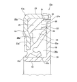
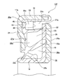
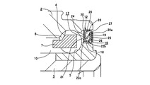
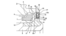
- FIG. 1 shows a first embodiment of the present invention.
- the rolling bearing unit with a combined seal ring according to the present invention including this embodiment is characterized in that, in addition to the elastic material constituting the seal ring, a plurality of seal lips provided on the elastic material, each of these seal lips.
- auxiliary seal lip having a lower rigidity than the above, the entry of foreign matter into the seal internal space of the combined seal ring is suppressed, and the adhesion of foreign matter to the seal lip closer to the external space among the seal lips is suppressed. It has a structure to keep the sealing performance of the combination seal ring good over a long period of time.
- the wheel is supported rotatably with respect to the suspension device. Since it is the same as that of the bearing unit, overlapping illustrations and descriptions are omitted or simplified, and the following description will focus on the features of this embodiment.
- the combination seal ring 12a incorporated in the rolling bearing unit with the combination seal ring according to the present embodiment includes an outer peripheral edge of the rotating-side circular ring portion 19 constituting the slinger 16 and a stationary-side cylindrical portion 23 constituting the core metal 20a of the seal ring 17a.
- a labyrinth seal 27a is provided between the inner peripheral surface of the elastic member 21a and a part of the inner peripheral surface. Further, a part of the elastic member 21a is provided outside the inner peripheral surface of the stationary side cylindrical portion 23 and the axially inner side surface of the stationary side annular portion 24 that constitutes the core metal 20a together with the stationary side cylindrical portion 23.
- a thick-walled portion 29 in which the radial dimension and the axial dimension are larger than the thickness dimension of the other part is provided in the part where the radial outer side and the axial outer side are partitioned by the radial half.
- a ring-shaped stepped surface 30 that is an axially inner end surface of the thick portion 29 and a portion closer to the tip of the inner peripheral surface of the stationary cylindrical portion 23 (an axially inner half).
- the covered portion is smoothly continued by an outer diameter side curved surface 31 (corner R) whose cross-sectional shape is a quarter arc.
- the radius of curvature R 1 of the cross-sectional shape of the outer diameter side curved surface 31, is set to the width dimension W or more in the radial direction of the labyrinth seal 27a (R 1 ⁇ W). This facilitates the return of foreign matter that has entered the space portion present on the outer diameter side of the auxiliary seal lip 32 described below through the labyrinth seal 27a to the labyrinth seal 27a side.
- an auxiliary seal lip 32 extends from the radially inner end of the step surface 30 toward the rotation-side annular ring portion 19 (formed integrally with the elastic material 21a together with the seal lips 22a to 22c).
- the auxiliary seal lip 32 has a partially conical cylindrical shape extending in a slanting manner in a direction in which the diameter increases toward the inside in the axial direction with the stepped surface 30 as a base end.
- Such an outer peripheral surface of the base end portion of the auxiliary seal lip 32 and the stepped surface 30 are also smoothly continued by the inner diameter side curved surface 33 whose sectional shape is a quarter arc.
- the radius of curvature R 2 of the cross-sectional shape of the inner diameter side curved surface 33 while suppressing stress applied to the proximal end portion of the auxiliary sealing lip 32, the surface that easily deflected the auxiliary sealing lip 32 adequately, further, the labyrinth
- the foreign matter that has entered the space portion existing on the outer diameter side of the auxiliary seal lip 32 through the seal 27a is appropriately restricted from the viewpoint of facilitating the return to the labyrinth seal 27a side.
- the radius of curvature R 2 of the cross-sectional shape of the inner diameter side curved surface 33 is the same as or slightly larger than the thickness T of the base end portion of the auxiliary seal lip 32 (R 2 ⁇ T )is doing.
- auxiliary seal lip 32 As described above, foreign matter adheres to the seal lip 22a which is a side lip and is located on the inner diameter side of the auxiliary seal lip 32, which is a seal lip closer to the external space described in the claims. It does not require a high level of sealing performance. Rather, it is important to suppress an increase in rotational resistance (dynamic torque) of the rolling bearing unit with a seal ring incorporating the combination seal ring 12a by providing the auxiliary seal lip 32. For this reason, in the case of the present embodiment, an increase in frictional resistance due to the provision of the auxiliary seal lip 32 is suppressed by the following devices (1) to (3).
- the cross-sectional shape of the auxiliary seal lip 32 has a wedge shape with the thickness dimension decreasing toward the tip edge. By doing so, the elasticity of the tip of the auxiliary seal lip 32 is kept low, and the frictional resistance is not increased.
- the thickness dimension of the auxiliary seal lip 32 is sufficiently smaller than the thickness dimension of the seal lip 22a. Specifically, the thickness of the base end that is the thickest portion of the auxiliary seal lip 32 is 1 ⁇ 2 of the thickness of the base end that is the thinnest portion of the seal lip 22a. Hereinafter, more preferably 1/3 or less, but 1/5 or more in consideration of formability. By doing so, the elasticity of the entire auxiliary seal lip 32 is kept low, and the frictional resistance is not increased.
- the tightening margin of the auxiliary seal lip 32 is sufficiently smaller than the tightening margin of the seal lip 22a.
- the axial height of the auxiliary seal lip 32 (the amount of axial protrusion toward the rotating-side annular portion 19) is set to the axial direction of the seal lip 22a. It is sufficiently smaller than the height.
- the contact pressure between the tip edge of the auxiliary seal lip 32 and the axially outer side surface of the rotation-side annular ring portion 19 is suppressed to prevent the frictional resistance from increasing.
- the center axis of the seal ring 17a and the center axis of the slinger 16 are inclined as the vehicle turns. In this state, the front end edge of the auxiliary seal lip 32 may slightly float from the axially outer side surface of the rotating-side annular ring portion 19 (even if the tightening margin becomes zero or a slight gap is left).
- a wheel support rolling bearing unit incorporated in a part (rigid rear axle) that supports the rotation of a rear wheel that is a semi-floating suspension device (non-independent suspension device) and that does not give a rudder angle. If the center axis of the seal ring and the center axis of the slinger hardly tilt even during turning, the tip edge of the auxiliary seal lip is placed on the outer side in the axial direction of the rotating-side annular ring part, and a minute gap is formed. You may make it oppose through.
- the outer space 28a that exists in the radially outer portion than the seal lip 22a and communicates with the outer space via the labyrinth seal 27a is divided into two in the radial direction by the auxiliary seal lip 32. ing.
- the auxiliary seal lip 32 exists between the seal lip 22a and the labyrinth seal 27a.
- the axially outer end portion and the inner diameter side are partitioned by the step surface 30 and the auxiliary seal lip 32 at a portion communicating with the labyrinth seal 27a at the radially outer end portion of the outer space 28a.
- a small space 34 near the opening is provided.
- the inner and outer peripheral edges of the stepped surface 30 constituting the inner surface of the axially outer end of the small opening 34 are formed by the inner and outer curved surfaces 33 and 31, respectively. Smooth and continuous with both inner and outer peripheral surfaces. Furthermore, the outer peripheral surface of the auxiliary seal lip 32 continuing from the inner diameter side curved surface 33 is inclined in the direction toward the labyrinth seal 27a toward the tip. With such a configuration, the flow of foreign matter blown from the labyrinth seal 27a into the small space 34 close to the opening is converted and returned to the labyrinth seal 27a.
- the seal internal space 26a existing between the slinger 16 and the seal ring 17a Intrusion of foreign matter such as muddy water can be effectively prevented.
- foreign matter adheres to the outer peripheral surface of the seal lip 22a existing in the portion closest to the labyrinth seal 27a among the seal lips 22a to 22c. It is possible to prevent the behavior from being impaired and the sealing performance of the seal lip 22a from being deteriorated.
- the labyrinth seal 27a is separated from the outside by the step surface 30 and the auxiliary seal lip 32 that partition the axially outer end surface and inner peripheral surface of the opening-side small space 34.
- the space 28 a it is possible to prevent foreign matter from entering the small space 35 close to the anti-opening that exists on the inner diameter side of the auxiliary seal lip 32.
- the tip end portion of the seal lip 22a is closely opposed to the inner peripheral surface of the auxiliary seal lip 32 in the use state shown in FIG. Even when some pressure is applied to the surface, the auxiliary seal lip 32 is not deformed so as to be reversed (turned up) to the inner diameter side. That is, when the pressure in the small space 34 near the opening increases due to muddy water or the like that has entered through the labyrinth seal 27a, the auxiliary seal lip 32 tends to deform toward the inner diameter side. The auxiliary seal lip 32 is supported by the tip portion coming into contact with the inner peripheral surface of the auxiliary seal lip 32, and deformation of the auxiliary seal lip 32 is prevented. Thereby, the sealing performance of this auxiliary seal lip 32 can be maintained in a stable state.
- the auxiliary seal lip 32 is not greatly deformed radially inward regardless of the foreign matter that has entered the small space 34 close to the opening. Therefore, the foreign matter passes through the auxiliary seal lip 32. Thus, it does not enter the small space 35 near the anti-opening. In other words, the foreign matter that has entered the small opening 34 is stopped in the small opening 34. Further, foreign matter guided by the outer diameter side curved surface 31, the step surface 30 and the inner diameter side curved surface 33 and reaching the outer peripheral surface of the auxiliary seal lip 32 causes the outer peripheral surface of the auxiliary seal lip 32 to pass through the labyrinth seal. It flows radially outward toward 27a and is discharged to the external space through this labyrinth seal 27a.
- the foreign matter (muddy water containing a large amount of water) cleans the inside of the small space 34 near the opening, so that the solid matter is prevented from being deposited in the small space 34 near the opening. For this reason, it is possible to prevent a large amount of solid content from adhering to the seal lip 22a and impairing the movement of the seal lip 22a.
- the auxiliary seal lip 32 can effectively maintain the foreign matter intrusion preventing effect on the side opposite to the small space 35 near the opening, and further, the foreign matter adhesion preventing effect on the seal lip 22a over a long period of time.
- the durability of the rolling bearing unit incorporating the combination seal ring 12a can be ensured.
- the outer ring having the seal ring 17a fitted therein and the hub having the slinger 16 fitted externally are fixed. Based on the relative displacement, the seal ring 17a and the slinger 16 are relatively displaced, and the volume of the small space 34 near the opening is increased or decreased. In the case of the present embodiment, the volume of the small space 34 near the opening is smaller than the volume of the small space 35 near the opening, and the center O of the relative displacement between the outer ring 2 and the hub 3 serving as the oscillation center (FIG. 18).
- the volume change rate of the small space 34 near the opening due to the relative displacement is large. For this reason, the pumping action by this volume change can be enlarged, and the foreign matter accumulated in the small space 34 near the opening can be effectively discharged to the external space.
- the auxiliary seal lip 32 is a contact type seal lip
- the air sealed in the small space 35 near the anti-opening supports the auxiliary seal lip 32.
- the foreign matter accumulated in the space 34 does not enter the small space 35 near the counter opening.
- the auxiliary seal lip 32 is a non-contact type seal lip having a minute gap
- the air existing in the small space 35 near the opening is radially outward from the tip of the auxiliary seal lip 32. Because of the outflow, the foreign matter accumulated in the small space 34 near the opening does not enter the small space 35 near the counter opening.
- the portion of the inner circumferential surface of the thick portion 29 of the elastic member 21a that divides the outer diameter side of the small space 35 near the anti-opening has a larger diameter toward the auxiliary seal lip 32 toward the inner side in the axial direction.
- the concave surface is a partial conical shape. For this reason, if foreign matter such as muddy water passes between the tip edge of the auxiliary seal lip 32 and the inner side surface of the slinger 16 in the axial direction, Is guided along the inner peripheral surface of the thick portion 29 to the sliding contact portion or the proximity facing portion between the auxiliary seal lip 32 and the slinger 16.
- the auxiliary seal lip 32 has a small tightening margin and is thin, and is inclined in a radially outward direction toward the distal end edge.
- the auxiliary seal lip 32 has a small space close to the opening from the anti-opening small space 35.
- the sealing effect of blocking the fluid or the like toward 34 is weak.
- the foreign matter led to the inner peripheral surface of the auxiliary seal lip 32 along the inner peripheral surface of the thick portion 29 is slidably contacted or closely opposed to the auxiliary seal lip 32 and the slinger 16.
- the portion passes from the inside in the radial direction to the outside in the radial direction, is sent to the small space 34 near the opening, further passes through the labyrinth seal 27a, and is discharged to the external space.
- auxiliary seal lip 32 As described above, in the structure of this embodiment, by providing the auxiliary seal lip 32, foreign matter that reaches the outer peripheral surface of the seal lip 22a and remains attached to the outer peripheral surface of the seal lip 22a is extremely small. Slightly reduced.
- the auxiliary seal lip 32 provided in order to obtain such operations and effects is small in thickness and has a slight or zero tightening allowance. For this reason, the increase in the rotational torque of the rolling bearing unit with the combined seal ring accompanying the addition of the auxiliary seal lip 32 is zero or slight.
- the width W in the radial direction of the labyrinth seal 27a provided between the outer peripheral edge of the rotating-side circular ring portion 19 and the inner peripheral surface of the stationary-side cylindrical portion 23 is the outer ring assumed in design. It is set so that it makes slight contact at the maximum relative inclination between the hub and the hub. Since the inner peripheral surface of the stationary-side cylindrical portion 23 is covered with the elastic material 21a, even if such setting is performed, the combination seal ring 12a is not seriously damaged. By setting the width dimension W to a minimum, the labyrinth seal 27a can be improved in sealing performance, and foreign matter intrusion into the small opening 34 can be suppressed to a minimum.
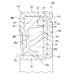
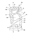
- FIG. 3 shows a second embodiment of the present invention.
- a magnetic powder is dispersed in a polymer material such as rubber or synthetic resin on the inner surface in the axial direction of the rotating-side annular ring portion 19 that constitutes the slinger 16 so that the whole is formed into an annular shape.
- a magnet encoder 25a is attached to the entire circumference.
- the encoder 25a is formed so as to cover the distal end side peripheral edge (outer peripheral edge) of the rotation-side annular ring portion 19, and is covered on the inner peripheral surface of the stationary-side cylindrical portion 23 that constitutes the core metal 20a of the seal ring 17a.
- a labyrinth seal 27a is formed between the elastic member 21a and a part thereof. Further, as the elastomer constituting the elastic material 21a of the seal ring 17a, a material containing a wax component and having good water repellency is used.
- the axial length of the labyrinth seal 27a can be increased by the thickness of the encoder 25a, so that the sealing effect can be enhanced. Furthermore, since the tip side peripheral edge (outer peripheral edge) of the rotating-side circular ring portion 19 that is a shear surface is covered with the encoder 25a to improve the surface roughness to a smooth surface, mud is formed on the inner surface portion of the labyrinth seal 27a. Can be prevented from being trapped and deposited.
- the encoder 25a is formed by injection molding on the inner side surface in the axial direction of the rotating side annular portion 19, the outer side surface in the axial direction of the rotating side annular portion 19 is pressed against the reference surface (the bottom surface of the mold). Surface). Therefore, it is possible to prevent the polymer material constituting the encoder 25a from adhering to the axially outer side surface where the auxiliary seal lip 32 and the seal lip 22a are in sliding contact.
- the outer side space 28a including the inner surface of the opening-side small space 34 is constituted by the smooth surface of the elastic material 21a, whereby the auxiliary seal lip 32 and the Accumulation of foreign matter on the surface of the seal lip 22a can be more sufficiently suppressed. Since the configuration and operation of the other parts are the same as those of the first embodiment described above, the same parts are denoted by the same reference numerals, and redundant description is omitted.
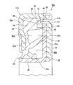
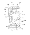
- FIG. 4 shows a third embodiment of the present invention.
- an encoder 25b made of a permanent magnet is attached to the entire inner periphery of the inner side surface in the axial direction of the rotating-side circular ring portion 19 constituting the slinger 16.
- a part of the polymer material constituting the encoder 25b is passed over the outer peripheral edge of the rotating side annular part 19 and the stationary side annular part constituting the core metal 20a of the seal ring 17a.
- An annular protrusion 36 is formed so as to protrude over the entire circumference toward the portion 24 side.
- the inner circumferential surface of the ridge 36 is a partially conical inclined surface 37 that is inclined in a direction in which the inner diameter increases toward the tip edge (outward in the axial direction).
- a labyrinth seal 27b is formed including a portion between the outer peripheral surface of the ridge 36 and the inner peripheral surface of the stationary cylindrical portion 23.
- a part of the elastic material 21a constituting the seal ring 17a covers the inner peripheral surface of the stationary side cylindrical portion 23 constituting the cored bar 20a, and the encoder 25b
- the portion of the labyrinth seal 27b that is in close proximity to the outer edge and the outer peripheral surface of the ridge 36 is inclined in a direction in which the inner diameter becomes smaller toward the stationary-side annular ring portion 24, and is a partial conical surface shape.
- the inclined surface 38 is used.
- the length of the labyrinth seal 27b in the axial direction is higher than the height of the protrusion 36 in the axial direction as compared with the second embodiment described above. Since it can be made wider by as much, the sealing effect can be further enhanced. Further, since the protrusion 36 protrudes so as to cover the sliding contact portion or the proximity facing portion between the auxiliary seal lip 32 and the axially outer side surface of the rotation-side annular ring portion 19, the muddy water or the like that the wheel jumps up It is possible to more reliably prevent the splashes from colliding with the sliding contact portion or the proximity facing portion.
- the inner peripheral surface of the stationary side cylindrical portion 23 is the inclined surface 38 and the inner peripheral surface of the protrusion 36 is also the inclined surface 37, so that foreign matters such as mud are present on the inner surface of the small space 34 near the opening. Accumulation can be prevented more effectively. That is, the foreign matter adhering to the inclined surface 37 on the inner peripheral surface of the protrusion 36 is caused by the centrifugal force based on the rotation of the slinger 16, and the foreign matter attached to a part of the inclined surface 38 of the elastic member 21 a is this centrifugal force. As a result, the foreign matter is drawn to the external space through the labyrinth seal 27b, and the foreign matter can be prevented from accumulating as described above.
- a polymer such as polytetrafluoroethylene resin (PTFE) having high water repellency, polyphenylene sulfide resin (PPS), modified polyamide resin or the like is used as the polymer material constituting the encoder 25b, mud or the like.
- PTFE polytetrafluoroethylene resin
- PPS polyphenylene sulfide resin
- modified polyamide resin or the like
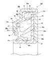
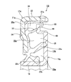
- FIG. 5 shows a fourth embodiment of the present invention.
- the stationary-side annular ring portion 39 which is disposed concentrically with the stationary-side annular portion 24a constituting the seal ring 17b.
- a stepped shape including an outer diameter side inclined portion 40, a distal end side annular ring portion 41, and an inner diameter side inclined portion 42.
- the proximal-side annular ring portion 39 is located closest to the outer diameter, and is bent at a right angle from the axially outer end of the stationary-side cylindrical portion 23a toward the radially inner side.
- the outer diameter side inclined portion 40 is a portion corresponding to the inclined portion described in the claims, and continues radially inward from the inner peripheral edge which is the front end side peripheral edge of the base end side annular ring portion 39.
- the inclination toward the outer side in the axial direction is inclined toward the inner peripheral edge which is the tip side.
- the distal end side annular portion 41 is a portion that is continuous radially inward from the inner peripheral edge of the outer diameter side inclined portion 40 and is parallel to the proximal end side annular portion 39.
- the inner diameter side inclined portion 42 is a portion continuous radially inward from the inner peripheral edge of the distal end side annular ring portion 41 so as to support the proximal end portions of the seal lips 22a, 22b, 22c. It is inclined in the direction toward the axially inward direction toward the inner peripheral edge side.
- the base end portion of the auxiliary seal lip 32 formed on a part of the elastic material 21c is positioned at the inner peripheral edge portion (front end side portion) of the base end side annular portion 39. Then, the thickness dimension of the portion of the elastic material 21c where the base end portion of the auxiliary seal lip 32 is continuous is made to substantially coincide with the thickness dimension of the base end portion of the auxiliary seal lip 32 (the larger one). The difference is within 40%, preferably within 20%). Thereby, the sealing performance between the front end edge of the auxiliary seal lip 32 and the axially outer side surface of the rotating-side annular ring portion 19 constituting the slinger 16 is improved.
- the thickness dimension of the portion of the elastic material 21c where the base end portion of the auxiliary seal lip 32 is continuous is made smaller than that in the first to third embodiments (the thick portion 29 is formed). Lost) Then, during the injection molding of the elastic material 21c, the shrinkage amount of the portion where the base end portion of the auxiliary seal lip 32 is continuous is suppressed, and the shape of the auxiliary seal lip 32 is distorted as much as possible after the injection molding. I try to keep it small.
- the rubber material constituting the elastic material 21c shrinks by about 1.2 to 3.5% after injection molding, so-called shrinkage occurs. Therefore, when the base end portion of the auxiliary seal lip 32 is positioned at the thick portion 29 as in the first to third embodiments, the auxiliary seal lip 32 is affected by the shrinkage of the thick portion 29. May be distorted. And when it is distorted, the state of the engagement portion between the tip edge of the auxiliary seal lip 32 and the axially outer side surface of the rotation-side annular ring portion 19 of the slinger 16 becomes unstable. Sealability tends to be unstable.
- the inclination angle of the auxiliary seal lip 32 with respect to the central axis of the seal ring 17b is reduced (the auxiliary seal lip 32 stands up), and the tip side edge of the auxiliary seal lip 32 is greatly bent. It is easy to be in a so-called belly contact state with a large area in contact with the axially outer side surface of the ring portion 19, and it becomes difficult to obtain stable sealing performance. Further, when the thick portion 29 is simply eliminated and the auxiliary seal lip is lengthened correspondingly, the rigidity of the auxiliary seal lip is excessively lowered, and it is difficult to obtain stable sealing performance. In addition, the volume of the small space 34 near the opening is increased, and the above-described foreign matter discharge effect due to the pump action is reduced.
- auxiliary seal lip is increased in order to ensure the required rigidity by increasing the length of the auxiliary seal lip, the relationship between the tip edge of the auxiliary seal lip and the axially outer surface of the rotating side annular ring portion will be described.
- the surface pressure at the joint increases, and the dynamic torque of the rolling bearing unit with the combined seal ring increases.
- the proximal end side annular portion 39 is present on the axially inner side (side closer to the rotating side annular portion 19) than the distal end side annular portion 41. . And by this amount, without changing the size and shape of each seal lip 22a, 22b, 22c (while keeping the same as in the first to third embodiments), the auxiliary seal lip 32 of the elastic material 21c. The thickness dimension of the portion where the base end portion is continuous can be reduced.
- the degree of shrinkage occurring in this portion is reduced, distortion of the shape of the auxiliary seal lip 32 is reduced, and the tip edge of the auxiliary seal lip 32 and the axial direction of the rotation-side annular ring portion 19 of the slinger 16 are reduced.
- the state of the engaging portion with the outer surface can be stabilized, and the sealing performance of the engaging portion can be improved.
- the rigidity of the stationary side cylindrical part 23a can be increased by the amount that the axial dimension (width) of the stationary side cylindrical part 23a can be reduced. Further, during the injection molding of the sealing material 21c, it is difficult for elastic deformation such as buckling to occur in the stationary side cylindrical portion 23a, and among the sealing material 21c, the axially inner half portion of the stationary side cylindrical portion 23a. A portion surrounding the inner and outer peripheral surfaces can be stably molded. It should be noted that the outer diameter of the tip side annular portion 41 is larger than the outer diameter of the seal lip 22a in the free state.
- a plurality of circumferential locations on the inner side surface in the axial direction of the cored bar 20b are directed toward the inner surface of the cavity of the mold and are held down by holding pins (not shown).
- the core bar 20b is prevented from being lifted from the inner surface, and the seal lips 22a, 22b, 22c can be accurately injection-molded.
- the small recess 43 shown in FIG. 5 is a mark that presses the tip of the holding pin. However, the bottom of the small recess 43 is covered with a part of the sealing material 21c.
- the axial position of the axial inner surface of the base end side annular portion 39 is the axial direction of the axial inner end surface of the thick portion 29 in the first to third embodiments. It is almost coincident with the position (see FIGS. 1 to 4). However, these two axial positions do not necessarily have to coincide with each other.
- the auxiliary seal lip 32 can be appropriately adjusted according to the performance such as flexibility and rigidity required. Since the configuration and operation of the other parts are the same as those of the second embodiment described above, the same parts are denoted by the same reference numerals, and redundant description is omitted.
- FIG. 6 shows a fifth embodiment of the present invention.
- the radial ring intermediate portion 24b of the cored bar 20c which forms the seal ring 17c together with the elastic member 21d
- a protrusion 44 is formed.
- the ridge 44 has a trapezoidal cross-sectional shape and is formed over the entire circumference in a state of projecting inward in the axial direction toward the rotation-side annular portion 19 of the slinger 16.
- the proximal end portion of the auxiliary seal lip 32 is positioned at the distal end portion of the protrusion 44.
- the thickness of a portion of the elastic material 21d located on the axially outer side of the base end portion of the auxiliary seal lip 32 is set to the auxiliary seal lip 32.
- the thickness of the base end is substantially the same.
- the protrusion 44 has an L-shaped intermediate material (substantially the same shape as the core metal 20a described in FIGS. 1 to 4), and then a flat plate portion (annular portion) of the intermediate material. It is made by pinching strongly between the punch and the die and plastically deforming (overhanging).
- the axial dimension (width) of the stationary cylindrical portion 23 existing at the outer peripheral edge portion of the core metal 20c is sufficiently ensured, and the core metal 20c with respect to the outer ring is secured. It is possible to prevent deformation of the auxiliary seal lip 32 while ensuring the fitting strength and stabilizing the posture after the fitting.
- the inner diameter of the protrusion 44 is made larger than the outer diameter of the seal lip 22a in a free state in order to prevent the core bar 20c from being lifted from the inner surface of the cavity by the holding pin. ing.
- a ridge 46 is formed in a radial intermediate portion of the outer side surface of the stationary side annular ring portion 24b in a part of the elastic material 21d.
- This protrusion 46 is a rotating side circle constituting the detection surface of the encoder 25a (when the encoder 25a is provided) or the slinger 16 in a state where the combination seal ring 12e is overlapped in the axial direction and packed (bar wound packaging). It contacts the inner side surface of the ring portion 19 in the axial direction (when no encoder is provided). Then, the surface to be detected is prevented from being damaged, and the seal ring 17c and the slinger 16 of the adjacent combination seal ring 12e are prevented from sticking.
- the inner diameter side inclined portion 42 (see FIG. 5) as in the fourth embodiment described above can be provided at the inner diameter side end of the core bar 20c. Since the configuration and operation of the other parts are the same as those of the second embodiment described above, the same parts are denoted by the same reference numerals, and redundant description is omitted.
- FIG. 7 shows a sixth embodiment of the present invention.
- a concave portion 45 is formed in the inner end surface in the axial direction of the thick portion 29a.
- the thickness dimension of the inner end portion in the radial direction of the thick portion 29 a located between the concave portions 45 in the circumferential direction and radially inward of the concave portions 45 is determined by the auxiliary seal lip 32.
- the thickness dimension of the base end is substantially the same.
- the base end part of this auxiliary seal lip 32 is located in the radial direction inner end part among the axial direction inner end surfaces of the said thick part 29a.
- the auxiliary seal lip 32 it is possible to prevent the auxiliary seal lip 32 from being deformed due to the shrinkage generated after the injection molding of the elastic material 21e, thereby ensuring the sealing performance.
- the volume of the small space 34a close to the opening existing between the auxiliary seal lip 32 and the labyrinth seal 27a can be increased by the provision of the respective recesses 45. For this reason, while the foreign matter discharge effect by the pump action described above is reduced, the effect of weakening the momentum of the foreign matter that has passed through the labyrinth seal 27a and entered the small opening 34a is increased.
- the stationary-side circular ring portion 24 of the cored bar 20 is pressed against the inner surface of the cavity by a holding pin at the back surface portion of each recess 45. Since the configuration and operation of the other parts are the same as those of the first embodiment described above, the same parts are denoted by the same reference numerals, and redundant description is omitted.
- FIG. 8 shows a seventh embodiment of the present invention.
- the seal ring 17d constituting the combination seal ring 12g incorporated in the rolling bearing unit with the combination seal ring of this embodiment, as in the case of the fourth to fifth embodiments shown in FIGS.
- the thickness dimension of the portion of the material 21f where the base end portion of the auxiliary seal lip 32 is continuous is reduced.
- the distortion of the shape of the auxiliary seal lip 32 is minimized as much as possible.
- the core bar 20a having the same shape as that of the first to third embodiments shown in FIGS. 1 to 4 is used.
- the total length of the auxiliary seal lip 32 is regulated to an appropriate value.
- the portion near the tip in the radial direction middle portion of the rotation-side annular portion 19a of the slinger 16a is bent over the entire circumference in the thickness direction of the rotation-side annular portion 19a. ing.
- the portion closer to the outer diameter in the radial direction of the rotating side annular portion 19a is directed to the stationary side annular portion 24 of the core metal 20a, and is bent by less than 90 degrees to form the inclined portion 47.
- a tip side flat plate portion 48 is provided in a state of being continuous radially outward from the inclined portion 47.
- the distal end side flat plate portion 48 is positioned closer to the stationary side annular portion 24 than the intermediate portion or the base end portion of the rotating side annular portion 19a (this intermediate portion to It is offset to the stationary side annular part 24 side with respect to the base end part).
- the front end edge of the auxiliary seal lip 32 is slidably contacted or closely opposed to the axial side surface of the front end flat plate portion 48 over the entire circumference.
- one of the elastic members 21f covering the outer peripheral edge of the rotation side circular ring portion 19a (the tip side flat plate portion 48) and the inner peripheral surface of the stationary side cylindrical portion 23 is provided.
- the labyrinth seal 27a provided between the inner peripheral surface and the inner peripheral surface is located on the outer side in the axial direction as compared with the case of the first embodiment described above. For this reason, it is difficult for foreign matter to reach the labyrinth seal 27a, and the effect of preventing foreign matter from entering the labyrinth seal 27a can be further improved. Since the configuration and operation of the other parts are the same as those in the fourth to fifth embodiments, the same parts are denoted by the same reference numerals, and redundant description is omitted.
- FIG. 9 shows an eighth embodiment of the present invention.
- the portion closer to the outer diameter in the radial direction of the rotation side ring portion 19b is the stationary side circle of the core metal 20a.
- a short cylindrical step portion 49 is formed by bending the ring portion 24 at a right angle, and a tip side flat plate portion 48 is provided by bending the tip edge of the step portion 49 at a right angle outwardly in the radial direction. .
- the tip edge of the auxiliary seal lip 32 is slidably contacted or closely opposed to the axial side surface of the tip side flat plate portion 48 over the entire circumference. Since the configuration and operation of the other parts are the same as in the case of the above-described seventh embodiment, the same parts are denoted by the same reference numerals, and redundant description is omitted.
- FIG. 10 shows a ninth embodiment of the present invention.
- a part of the elastic material 21g is formed on the inner peripheral surface of the stationary side cylindrical portion 23 of the core metal 20a.
- a locking lip 50 is intermittently provided in the circumferential direction in a state of projecting inward in the radial direction at the inner diameter side portion of the portion closer to the distal end of the stationary side cylindrical portion 23 in the covered portion.
- the locking lip 50 is located on the opposite side of the stationary side annular portion 24 of the cored bar 20a with respect to the axial direction across the rotation side annular portion 19b of the slinger 16a. Further, the inner diameter of the locking lip 50 is smaller than the outer diameter of the rotation-side circular ring portion 19b. Therefore, the front end portion of the locking lip 50 and the front end portion of the rotation-side annular ring portion 19b overlap each other in the axial direction.
- the slinger 16a and the above-described slinger 16a which constitutes the combination seal ring 12i, even in a state before assembly to a predetermined portion based on the engagement between the distal end portion of the locking lip 50 and the distal end portion of the rotation-side annular ring portion 19b.
- the separation from the seal ring 17d is prevented.
- the locking lip 50 is provided intermittently in the circumferential direction, it has an appropriate elasticity and does not hinder the discharge of foreign matter that has entered the small space 34 near the opening. Since the configuration and operation of the other parts are the same as those in the above-described eighth embodiment, the same parts are denoted by the same reference numerals, and redundant description is omitted.
- FIG. 11 shows a tenth embodiment of the present invention.
- the permanent magnet encoder 25b is disposed on the entire inner surface in the axial direction of the rotating side ring portion 19a. Attached to Further, a portion of the outer peripheral surface of the encoder 25b having the largest outer diameter is provided at a portion closer to the inner side in the axial direction of the intermediate portion of the outer peripheral surface in the axial direction.
- FIG. 12 shows an eleventh embodiment of the present invention.
- the outer peripheral surface of the encoder 25c made of a permanent magnet attached to the inner surface in the axial direction of the rotary side ring portion 19a.
- the portion having the largest outer diameter is located on the opposite side of the rotation-side annular portion 19a with respect to the axial direction with the locking lip 50 interposed therebetween.
- FIG. 13 shows a twelfth embodiment of the present invention.
- the shape of the base end portion of the auxiliary seal lip 32a is cylindrical, and the intermediate portion or the tip end edge.
- the shape of the part is a partial conical cylinder. Accordingly, the intermediate portion or the tip edge portion of the auxiliary seal lip 32a is inclined in a direction in which the diameter increases toward the tip edge.
- the tip edge of the auxiliary seal lip 32a is opposed to the axial side surface of the rotation-side annular ring portion 19 in a non-contact state over the entire circumference.
- a labyrinth seal is provided over the entire circumference between the distal end edge of the auxiliary seal lip 32a and the axially outer side surface of the rotating-side annular ring portion 19.
- the foreign matter does not enter the small space 35 near the counter opening that exists on the inner diameter side of the auxiliary seal lip 32a. Further, the foreign matter blocked in the outer peripheral surface portion of the auxiliary seal lip 32a in this way flows along the inclination of the outer peripheral surface of the auxiliary seal lip 32a and is accompanied by the rotation of the rotating side annular ring portion 19. Then, it is pulled by the air flow induced (by the swinging effect of the slinger 16) and discharged from the labyrinth seal 27a to the external space. Since the configuration and operation of the other parts are the same as those of the second embodiment shown in FIG. 3 described above, the same parts are denoted by the same reference numerals, and redundant description is omitted.
- FIG. 14 shows a thirteenth embodiment of the present invention.
- the auxiliary seal lip 32b has an arcuate cross-section with a concave outer peripheral surface.
- the tangential direction of the portion of the front end portion of the auxiliary seal lip 32b facing the outer side surface in the axial direction of the rotation side ring portion 19 of the slinger 16 is parallel to the outer side surface in the axial direction. It is made to face and oppose to the outer surface in the direction over the entire circumference.
- the total length of the auxiliary seal lip 32b can be made longer than that of the twelfth embodiment described above. Further, since the diameter of the tip edge of the auxiliary seal lip 32b can be made larger than the diameter of the base end portion, the rigidity of the auxiliary seal lip 32b can be appropriately reduced.
- the auxiliary seal lip 32b can be easily bent by the foreign matter that has entered the small space 34 near the opening. That is, the tip of the auxiliary seal lip 32b can be easily brought into sliding contact with the outer surface in the axial direction in a state where the pressure rise in the small space 34 near the opening is small.
- FIG. 15 shows a fourteenth embodiment of the present invention.
- the auxiliary seal lip 32c is radially outward from the tip edge of the intermediate portion of the partially conical cylindrical shape.
- the bent collar 51 is provided with a bent ring. And this collar part 51 and the axial direction outer side surface of the rotation side annular ring part 19 are made to oppose each other over the perimeter. Since the configuration and operation of other parts are the same as those in the thirteenth embodiment described above, the same parts are denoted by the same reference numerals, and redundant description is omitted.
- FIG. 16 to 17F show a fifteenth embodiment of the present invention.
- the rotation-side annular ring portion 19 of the slinger 16 is out of the tip edge 52 of the auxiliary seal lip 32d.
- the shape in the circumferential direction of the portion that is in sliding contact with the axially outer side surface is an uneven shape.
- the tip edge 52 is intermittently brought into sliding contact with the axially outer side surface in the circumferential direction.
- the uneven shape of the tip edge 52 is not particularly limited.
- the rectangular recesses and protrusions are alternately continued, the sinusoidal waveform as shown in FIG. 17B, and the tip edge 52 as shown in FIG. 17C.
- An epicycloid curve shape or the like as shown in 17F can be adopted.
- 17D, 17E, and 17F may have the entire tip edge 52 in the shape, or only the one edge that is in sliding contact with the one side surface in the axial direction. Regardless of which shape is adopted, only the convex portions of the tip edge 52 are in sliding contact with the outer surface in the axial direction of the rotation-side annular ring portion 19, and between the concave portions and the outer surface in the axial direction. A large number of minute gaps are intermittently present in the circumferential direction.
- the portion of the tip edge 52 that is in sliding contact with the axially outer side surface of the rotation-side annular ring portion 19 does not necessarily need to have an uneven shape in the circumferential direction during injection molding. That is, the elastic material 21h including the auxiliary seal lip 32 is made of a material having a slight swellability (about 5%) with respect to water such as nitrile rubber, and the tip edge 52 is formed extremely thin. Then, the tip edge 52 can be formed into an uneven shape by swelling the tip edge 52 with moisture adhering to the tip edge 52.
- the elastic material 21h is made of a material having swelling property
- the tip edge 52 expands, and between the axially outer side surfaces of the rotation-side annular ring portion 19, The tightening allowance is increased or the gap is reduced, so that the effect of preventing the entry of foreign matter can be further improved.
- the leading edge 52 contracts, so that the tightening margin is reduced or the gap is increased, and the sliding resistance by the auxiliary seal lip 32d can be reduced.
- the rolling bearing unit with a combined seal ring according to the present invention is most preferably implemented as a wheel bearing rolling bearing unit for supporting a vehicle wheel with respect to a suspension device from the viewpoint of sufficiently obtaining its functions and effects.
- the present invention can be implemented without being limited to the wheel bearing rolling bearing unit.
- a combination seal ring may be used.
- a combination seal ring that is a feature of the present invention is incorporated on the outer side in the axial direction of the wheel bearing rolling bearing unit as necessary.
- the inside and outside in the axial direction with respect to the combination seal ring is opposite to the above description.
- the structure of the fourth to fifth embodiments shown in FIGS. 5 to 6, or the structure of any of the seventh to eleventh embodiments shown in FIGS. 8 to 12, and the structures of FIGS. It can be combined with any of the structures of the twelfth to fifteenth embodiments shown in 17F.
- the present invention can also be applied to an outer ring rotating type rolling bearing unit with a seal ring.
- the slinger is fitted and fixed to the outer diameter side race ring member that rotates during use, and the seal ring is fitted and fixed to the inner diameter side race ring member that does not rotate during use. Accordingly, the inside and outside in the radial direction are opposite to those in the illustrated embodiments.
Abstract
組み合わせシールリング12aを構成するスリンガ16とシールリング17aとの間のシール内部空間26a内への異物の侵入を抑えて、このシールリング17aに設けたシールリップ22aの動きを確保できる構造を実現する。 前記スリンガ16を構成する回転側円輪部19の外周縁と、前記シールリング17aを構成する芯金20の静止側円筒部23の内周面との間に、ラビリンスシール27aを設ける。又、前記シールリング17aを構成する弾性材21aの一部に厚肉部29を、全周に亙って形成し、この厚肉部29に、各シールリップ22a~22cよりも剛性が低い補助シールリップ32を、全周に亙り設ける。この補助シールリップ32より、前記異物がシールリップ22aに付着し、このシールリップ22aの動きが阻害される事を防止する。
Description
本発明は、例えば自動車の車輪を懸架装置に対して回転自在に支持する為の転がり軸受ユニットのうち、回転側軌道輪と静止側軌道輪との互いに対向する周面同士の間に存在して複数個の転動体を設置した軸受内部空間の端部開口を、スリンガとシールリングとから成る組み合わせシールリングにより塞いで成る、組み合わせシールリング付転がり軸受ユニットの改良に関する。具体的には、前記スリンガと前記シールリングとの間に存在するシール内部空間に入り込む異物の量を抑える事により、前記組み合わせシールリングによるシール性を、長期間に亙って良好に維持できる構造の実現を図るものである。
自動車の車輪等を懸架装置に対して回転自在に支持する為の転がり軸受ユニットとして、例えば特許文献1には、図18に示す様な車輪支持用転がり軸受ユニットの構造が記載されている。この図18に示した転がり軸受ユニット1は、静止側軌道輪である外輪2と回転側軌道輪であるハブ3とを互いに同心に配置している。そして、この外輪2の内周面に設けた、それぞれが静止側軌道である複列の外輪軌道4、4と、前記ハブ3の外周面に設けた、それぞれが回転側軌道である複列の内輪軌道5、5との間に、それぞれが転動体である玉6、6を、両列毎に複数個ずつ配置している。これら各玉6、6は、それぞれ保持器7、7により、転動自在に保持している。この様な構成により、前記外輪2の内径側に前記ハブ3を、回転自在に支持している。前記懸架装置に対し前記車輪等を回転自在に支持するには、前記外輪2の外周面に設けた静止側フランジ8を前記懸架装置に対しねじ止め固定すると共に、前記ハブ3の軸方向外端部(軸方向に関して外とは、車両への組み付け状態でこの車両の幅方向外側となる、各図の左側を言う。これに対して、この車両の幅方向内側となる、各図の右側を、軸方向に関して内と言う。)外周面に形成した回転側フランジ9に、前記車輪及びディスクロータ等の制動用回転体をねじ止め固定する。
前記外輪2の内周面と前記ハブ3の外周面との間で前記各玉6、6を設置した軸受内部空間10の両端開口は、それぞれシールリング11と組み合わせシールリング12とにより、全周に亙り塞いでいる。このうち、前記軸受内部空間10の軸方向外端側開口を塞ぐシールリング11は、金属板製の芯金13により、ゴムの如きエラストマー製の弾性材14を補強して、全体を円環状に構成して成る。又、この弾性材14は、複数本(図示の例では3本)のシールリップ15a、15b、15cを有する。そして、このうちの芯金13を前記外輪2の内周面の軸方向外端部に締り嵌めで内嵌した状態で、前記各シールリップ15a、15b、15cの先端縁を前記回転側フランジ9の軸方向内側面又は前記ハブ3の中間部外周面に、それぞれ全周に亙り摺接させている。
又、前記組み合わせシールリング12は、スリンガ16とシールリング17とを組み合わせて成る。このうちのスリンガ16は、金属板を曲げ成形する事により断面L字形で全体を円環状に構成したもので、回転側円筒部18と、この回転側円筒部18の軸方向内端縁から径方向外方に折れ曲がった回転側円輪部19とから成る。この様なスリンガ16は、前記回転側円筒部18を前記ハブ3(ハブ本体と共にこのハブ3を構成する内輪)の軸方向内端部に締り嵌めで外嵌する事により、このハブ3に対し固定している。又、前記シールリング17は、金属板製の芯金20と弾性材21とを備える。この弾性材21は、複数本(図示の例では3本)のシールリップ22a、22b、22cを備える。又、前記芯金20は、金属板を曲げ成形する事により断面L字形で全体を円環状に構成したもので、静止側円筒部23と、この静止側円筒部23の軸方向外端縁から径方向内方に折れ曲がった静止側円輪部24とから成る。この様な芯金20を備えた前記シールリング17は、前記静止側円筒部23を前記外輪2の軸方向内端部に締り嵌めで内嵌する事により、この外輪2に固定している。又、この状態で、前記シールリップ22aの先端縁を前記回転側円輪部19の軸方向外側面に、前記各シールリップ22b、22cの先端縁を前記回転側円筒部18の外周面に、それぞれ全周に亙り摺接させている。
尚、上述の様な組み合わせシールリング12を構成するスリンガ16の回転側円輪部19の軸方向両側面のうち、前記回転側円筒部18の折れ曲がり方向と逆側の面(軸方向内側面)に、図19Aに示す様に、円輪状のエンコーダ25を、全周に亙り添着固定する場合もある。このエンコーダ25は、ゴム、合成樹脂等の高分子材料中に磁性粉を分散させて全体を円輪状とした、ゴム磁石、プラスチック磁石等の永久磁石製で、軸方向に着磁している。着磁方向は、円周方向に関して、交互に、且つ、等間隔で変化させている。従って、被検出面である、前記エンコーダ25の軸方向内側面には、S極とN極とが、円周方向に関して、交互に、且つ、等間隔で配置されている。この様なエンコーダ25の被検出面には、図示しない回転検出センサの検出部を対向させて、前記ハブ3と共に回転する車輪の回転速度を測定可能とする。そして、測定した、車輪の回転速度を表す信号を、アンチロックブレーキシステム(ABS)やトラクションコントロールシステム(TCS)等、車両の走行安定化装置の制御に利用する。この様な回転速度検出装置の構造及び作用に就いては、従来から周知であるし、本発明の要旨とも関係しない為、図示並びに詳しい説明は省略する。
これに対して、車輪の回転速度を検出する必要がない場合、或いは、別部分でこの回転速度を検出できる場合には、図19Bに示す様に、前記スリンガ16にエンコーダを設ける事はない。
何れにしても、前記軸受内部空間10の軸方向両端開口を前記シールリング11と前記組み合わせシールリング12とにより、それぞれ全周に亙り塞ぐ事で、前記軸受内部空間10内に存在するグリースの漏洩防止と、外部空間に存在する水分や塵芥等の異物がこの軸受内部空間10内に侵入する事の防止とを図っている。
何れにしても、前記軸受内部空間10の軸方向両端開口を前記シールリング11と前記組み合わせシールリング12とにより、それぞれ全周に亙り塞ぐ事で、前記軸受内部空間10内に存在するグリースの漏洩防止と、外部空間に存在する水分や塵芥等の異物がこの軸受内部空間10内に侵入する事の防止とを図っている。
前記車輪支持用の転がり転がり軸受ユニット1の耐久性を確保する為には、前記シールリング11及び前記組み合わせシールリング12のシール性を確保する事が重要である。一方、これらシールリング11及び組み合わせシールリング12は、使用時に泥水等がかかる、厳しい条件で使用される。特に、このうちの組み合わせシールリング12の場合には、前記スリンガ16と前記シールリング17とに囲まれたシール内部空間26内に入り込んだ泥水の水分が蒸発し、固形分(泥)だけがこのシール内部空間26内に溜まる可能性がある。図18、19A、19Bに示した従来構造の場合、このシール内部空間26のうち、最も外径側に存在するシールリップ22aよりも更に径方向外寄り部分に存在してラビリンスシール27を介して外部空間と連通した外部寄り空間28の容積が大きい為、この外部寄り空間28内に溜まる固形分の量が多くなり易い。そして、この外部寄り空間28内に溜まった固形分は、前記最も外径側に存在するシールリップ22aにも付着し、このシールリップ22aの動きを阻害する可能性がある。この結果、このシールリップ22aの先端縁の一部が前記スリンガ16の回転側円輪部19の軸方向外側面から浮き上がり、当該部分を通じて前記泥水等の異物が、前記シール内部空間26の更に奥にまで入り込む可能性がある。この様な現象は、水分の蒸発により凝縮し易い粘土質の土を含む泥水に於いて特に著しくなる。
前記ラビリンスシール27の隙間寸法(径方向に関する幅寸法)を小さくすれば、前記外部寄り空間28内に入り込む泥水等の異物を少なくできるが、この隙間寸法を小さくする事には限度がある。即ち、前記ラビリンスシール27の隙間寸法を極端に小さくすると、車両の旋回走行時に加わるモーメント荷重等により、前記外輪2と前記ハブ3とが相対的に傾いてラビリンスシール27の距離が縮まり、前記回転側円輪部19の端縁と前記静止側円筒部23の内周面とが激しく(強く)接触する可能性がある。この為、前記図18、19A、19Bに示した従来構造では、前記ラビリンスシール27の隙間寸法を極端に小さくする事は困難である。
組み合わせシールリングのシール性を向上させる為の構造として、特許文献2には、外輪に外嵌した第二のシールリングを構成する第二のシールリップの先端縁を、スリンガの回転側円輪部のうちで、シールリングと反対側の側面に、全周に亙り摺接させた構造が記載されている。この様な構造によれば、シール内部空間内への異物の侵入防止を十分に図れるが、部品点数が増えてコストが嵩む。又、前記第二のシールリングを設ける部分の設置スペースが嵩み、組み合わせシールリング付転がり軸受ユニットに隣接して設ける、他の物品との干渉防止の為、設計の自由度が限られる可能性がある。更に、前記第二のシールリップとして、組み合わせシールリング側に元々設けられているシールリップと同等の剛性を有するものを、この元々設けられているシールリップに足す状態で設ける為、摺接部が増えて回転抵抗(動トルク)が増大すると言った不利益もある。
本発明は、上述の様な事情に鑑み、転がり軸受ユニットを構成する静止側、回転側両軌道輪同士の間に存在する軸受内部空間の端部開口を塞ぐ、組み合わせシールリングを構成するスリンガとシールリングとの間のシール内部空間内への異物の侵入を抑えられる構造を実現して、このシールリングに設けたシールリップの動きを確保し、長期間に亙り優れたシール性能を維持できる構造を実現すべく発明したものである。
本発明の組み合わせシールリング付転がり軸受ユニットは、回転側軌道輪及び静止側軌道輪と、複数個の転動体と、組み合わせシールリングとを備える。
このうちの前記回転側軌道輪及び静止側軌道輪は、互いに同心に配置された状態で相対回転する。
又、前記各転動体は、これら回転側軌道輪及び静止側軌道輪の互いに対向する周面にそれぞれ設けられた、回転側軌道と静止側軌道との間に、転動自在に設けられている。
又、前記組み合わせシールリングは、前記回転側軌道輪と前記静止側軌道輪との互いに対向する周面同士の間に存在する軸受内部空間の端部開口を塞ぐもので、スリンガ及びシールリングから成る。
このうちのスリンガは、前記回転側軌道輪の周面の一部で前記静止側軌道輪の周面に対向する部分に嵌合固定されたもので、金属板を曲げ成形する事により断面L字形で全体を円環状に構成しており、回転側円筒部と、この回転側円筒部の軸方向端縁から前記静止側軌道輪に向けて径方向に折れ曲がった回転側円輪部とから成る。そして、前記回転側円筒部を前記回転側軌道輪の周面に嵌合する事で、この回転側軌道輪に固定している。
又、前記シールリングは、前記静止側軌道輪の一部で前記スリンガに対向する部分に嵌合固定されたもので、前記静止側軌道輪に嵌合固定される芯金と、この芯金に基端部を支持された、複数本のシールリップを有する弾性材とを備える。このうちの芯金は、金属板を曲げ成形する事により断面L字形で全体を円環状に構成しており、静止側円筒部と、この静止側円筒部の軸方向端縁から前記回転側軌道輪に向けて径方向に折れ曲がった静止側円輪部とから成る。そして、前記静止側円筒部を前記静止側軌道輪の周面に嵌合する事でこの静止側軌道輪に固定しており、前記各シールリップの先端部を、前記スリンガの表面に全周に亙り摺接させている。
更に、前記回転側円輪部の先端側周縁(径方向に関して前記回転側円筒部と反対側の周縁)と前記静止側円筒部の周面との間にラビリンスシールを設けている。
特に、本発明の組み合わせシールリング付転がり軸受ユニットに於いては、前記弾性材の基部で前記各シールリップよりも前記静止側円筒部に寄った部分に、これら各シールリップのうちで、少なくとも前記ラビリンスシールに最も近いシールリップである外部空間寄りシールリップよりも剛性が低い補助シールリップを、前記弾性材と一体に設けている。そして、この補助シールリップの先端縁を前記回転側円輪部の軸方向側面に、全周に亙って摺接若しくは近接対向させている。
上述の様な本発明を実施する場合に、好ましくは、前記静止側円筒部のうちで前記静止側円輪部を設けた側の周面を前記弾性材により覆う。そして、この弾性材のうちでこの静止側円輪部の軸方向側面を覆う部分の内外両周縁部と、前記周面を覆った部分及び前記補助シールリップの基部とを、断面形状が四分の一円弧状の曲面により滑らかに連続させる。
或いは、前記シールリングと前記スリンガとを組み合わせ、前記外部空間寄りシールリップの先端部を前記回転側円輪部の軸方向側面に弾性的に当接させた状態で、この外部空間寄りシールリップの先端縁を前記補助シールリップの片側周面に近接対向させる。近接対向させる程度は、前記ラビリンスシールを通じて入り込み、この補助シールリップの他側周面を押圧する流体によりこの補助シールリップが、径方向に反転しない(径方向にめくれない)程度とする。
或いは、前記弾性材の一部で前記静止側円筒部の周面と前記静止側円輪部の軸方向側面とにより径方向片側と軸方向片側とを仕切られた部分に、径方向及び軸方向の厚さ寸法が他の部分の厚さ寸法よりも大きくなった厚肉部を設ける。そして、この厚肉部の軸方向端面のうちで径方向に関して前記各シールリップ寄り部分に、前記補助シールリップの基端部を連続させる。
この様な態様を実施する場合に好ましくは、前記厚肉部の径方向中間部の円周方向複数箇所に、それぞれがこの厚肉部の軸方向端面に開口する凹部を形成する。そして、前記補助シールリップの基端部を、この厚肉部の軸方向端面のうちで、これら各凹部よりも前記各シールリップ寄り部分に位置させる。
この様な態様を実施する場合に好ましくは、前記厚肉部の径方向中間部の円周方向複数箇所に、それぞれがこの厚肉部の軸方向端面に開口する凹部を形成する。そして、前記補助シールリップの基端部を、この厚肉部の軸方向端面のうちで、これら各凹部よりも前記各シールリップ寄り部分に位置させる。
或いは、本発明を実施する場合に、前記静止側円輪部を、径方向に関して最も前記静止側円筒部寄りの基端側円輪部と、この基端側円輪部の先端側周縁から径方向に連続して、先端側に向かう程前記回転側円輪部から遠ざかる方向に傾斜した部分円すい状の傾斜部と、この傾斜部の先端側周縁から径方向に連続した、前記基端側円輪部と平行な先端側円輪部とを備えた段付形状とする。そして、前記補助シールリップの基端部を、前記基端側円輪部の先端側部分に位置させる。
或いは、前記静止側円輪部の径方向中間部に、前記回転側円輪部に向けて軸方向に突出する突条を全周に亙って形成する。そして、前記補助シールリップの基端部を、この突条の先端部分に位置させる。
或いは、前記静止側円輪部の径方向中間部に、前記回転側円輪部に向けて軸方向に突出する突条を全周に亙って形成する。そして、前記補助シールリップの基端部を、この突条の先端部分に位置させる。
或いは、前記回転側円輪部の径方向中間部先端寄り部分を、この回転側円輪部の厚さ方向に関し、全周に亙り曲げ形成する事により、前記回転側円輪部の先端部を中間部乃至基端部よりも前記静止側円輪部側に位置させる。そして、前記補助シールリップの先端縁を前記回転側円輪部の先端部の軸方向側面に、全周に亙って摺接若しくは近接対向させる。
この様な態様を実施する場合に、例えば、前記弾性材の一部を、前記静止側円筒部の内外両周面のうちで前記静止側軌道輪と反対側の周面を覆う状態で設ける。又、この周面を覆った前記弾性材のうちで、前記回転側円輪部の先端部を挟んで前記静止側円輪部と反対側部分に、この部分から前記回転側円筒部に向け径方向に突出する係止リップを、円周方向に関して間欠的に設ける。更に、この係止リップの先端部と前記回転側円輪部の先端部とを軸方向に関して互いに重畳させる。そして、前記スリンガと前記シールリングとの分離防止を図る。
又、本発明を実施する場合に、例えば、前記回転側軌道輪を径方向内側に存在する内径側軌道輪とし、前記静止側軌道輪を径方向外側に存在する外径側軌道輪とする。又、前記補助シールリップを、先端縁に向かう程直径が大きくなる方向に傾斜した形状とする。そして、この補助シールリップの先端縁を前記回転側円輪部の軸方向側面に、全周に亙り非接触状態で近接対向させて、これら補助シールリップの先端縁と前記回転側円輪部の軸方向側面との間にラビリンスシールを、全周に亙って設ける。
この様な態様を実施する場合に、例えば、前記補助シールリップのうちの少なくとも中間部乃至先端縁部分の形状を部分円すい筒状とする。
或いは、前記補助シールリップを、外周面が凹面である断面円弧状とする。そして、この補助シールリップの先端部のうちで前記回転側円輪部の軸方向側面と対向する部分の接線方向を、この軸方向側面と平行にする。
或いは、前記補助シールリップを、部分円すい筒状の中間部と、この中間部の先端縁から径方向外方に折れ曲がった円輪状の鍔部とから成るものとする。そして、この鍔部と前記回転側円輪部の軸方向側面とを全周に亙って近接対向させる。
或いは、前記補助シールリップを、外周面が凹面である断面円弧状とする。そして、この補助シールリップの先端部のうちで前記回転側円輪部の軸方向側面と対向する部分の接線方向を、この軸方向側面と平行にする。
或いは、前記補助シールリップを、部分円すい筒状の中間部と、この中間部の先端縁から径方向外方に折れ曲がった円輪状の鍔部とから成るものとする。そして、この鍔部と前記回転側円輪部の軸方向側面とを全周に亙って近接対向させる。
又、本発明を実施する場合に、例えば、前記補助シールリップの先端縁を前記回転側円輪部の軸方向側面に摺接させる。又、この先端縁のうちで少なくともこの軸方向側面に摺接する部分の周方向に関する形状を凹凸形状とする。そして、前記先端縁をこの軸方向側面に、周方向に関して間欠的に摺接させる。
又、本発明を実施する場合に、例えば、前記回転側円輪部の軸方向両側面のうちで前記静止側円輪部と対向する面と反対側の面に、高分子材料中に磁性粉を分散させて全体を円輪状として成る永久磁石製のエンコーダを添着する。そして、このエンコーダの周縁を前記静止側円筒部の周面に対向させて、当該部分にラビリンスシールを設ける。
この様な態様を実施する場合に好ましくは、前記エンコーダを構成する高分子材料の一部により、前記回転側円輪部の先端側周縁を越えて前記静止側円輪部の側に向け全周に亙り突出する突条を形成する。そして、この突条の周面と前記静止側円筒部の周面との間部分を含めて、前記ラビリンスシールとする。
更に、本発明を実施する場合に、例えば、前記回転側軌道輪を径方向内側に存在する内径側軌道輪とし、前記静止側軌道輪を径方向外側に存在する外径側軌道輪とする。そして、前記エンコーダの外周面のうちで外径が最も大きい部分を、前記係止リップを挟んで前記回転側円輪部と軸方向に関して反対側に存在させる。
或いは、前記エンコーダのうちで外径が最も大きい部分を、このエンコーダの外周面の軸方向中間部のうちの軸方向内側寄り部分に設ける。
上述の様に構成する本発明の組み合わせシールリング付転がり軸受ユニットによれば、組み合わせシールリングを構成するスリンガとシールリングとの間に存在するシール内部空間のうち、外部空間寄りシールリップに隣接する部分(前述の図18、19A、19Bに示した外部寄り空間28)への、泥水等の異物の侵入を効果的に防止できる。即ち、本発明の組み合わせシールリング付転がり軸受ユニットの場合には、ラビリンスシールを介して前記外部空間と連通する外部寄り空間が、補助シールリップにより、径方向に関して2分割される。そして、前記外部空間寄りシールリップと前記ラビリンスシールとの間に、前記補助シールリップが存在する状態となる。
この結果、前記外部空間寄りシールリップにまで達する泥水等の異物の量を僅少にし、この外部空間寄りシールリップに多量の固形分が付着して、この外部空間寄りシールリップの動きが損なわれる事を防止できる。この結果、長期間に亙り良好なシール性能を発揮させて、組み合わせシールリング付転がり軸受ユニットの耐久性を確保できる。
又、前記補助シールリップは、各シールリップよりも剛性が低い為、仮にこの補助シールリップの先端縁が前記スリンガの回転側円輪部と擦れ合っても、擦れ合い部に作用する摩擦力は低く抑えられる。この為、前記補助シールリップを設ける事に伴う、シールリング付転がり軸受ユニットの回転抵抗の増大は、極く僅少に抑えられる。
又、前記補助シールリップは、各シールリップよりも剛性が低い為、仮にこの補助シールリップの先端縁が前記スリンガの回転側円輪部と擦れ合っても、擦れ合い部に作用する摩擦力は低く抑えられる。この為、前記補助シールリップを設ける事に伴う、シールリング付転がり軸受ユニットの回転抵抗の増大は、極く僅少に抑えられる。
尚、前記ラビリンスシールを通過した泥水等の異物が前記補助シールリップに付着する事は、或る程度避けられない。但し、前記ラビリンスシールを通過する事で勢いを弱められた異物が、前記補助シールリップを弾性変形させて前記外部空間寄りシールリップにまで達する事は殆どない。従って、この補助シールリップを通過して前記外部空間寄りシールリップにまで達する異物の量は極く僅少に抑えられる。即ち、前記ラビリンスシールを通過する泥水等の異物の侵入速度や勢いが高い場合であっても、この異物がその勢いのまま前記補助シールリップを直撃する事はない。従って、この補助シールリップに異物が付着して、この補助シールリップによるシール性が低下しても、依然として前記外部空間寄りシールリップに達する異物の量を僅少に抑えられる。この為、この外部空間寄りシールリップに、この外部空間寄りシールリップのシール性を低下させる程に多量の異物が付着するまでには、相当の時間がかかる様になる。この結果、組み合わせシールリング付転がり軸受ユニットの耐久性を十分に向上させる事ができる。
[第1実施形態]
図1は、本発明の第1実施形態を示している。尚、本実施形態を含めて本発明の組み合わせシールリング付転がり軸受ユニットの特徴は、シールリングを構成する弾性材に、この弾性材に設けた複数本のシールリップに加えて、これら各シールリップよりも剛性が低い補助シールリップを設ける事により、組み合わせシールリングのシール内部空間内への異物の侵入を抑え、前記各シールリップのうちの外部空間寄りシールリップへの異物の付着を抑え、前記組み合わせシールリングのシール性能を長期間に亙って良好に保つ為の構造にある。その他の部分の構成及び作用に就いては、前述の図18に示した転がり軸受ユニット1を含め、例えば懸架装置に対して車輪を回転自在に支持する為、従来から広く知られている各種転がり軸受ユニットと同様であるから、重複する図示並びに説明は省略若しくは簡略にし、以下、本実施形態の特徴部分を中心に説明する。
図1は、本発明の第1実施形態を示している。尚、本実施形態を含めて本発明の組み合わせシールリング付転がり軸受ユニットの特徴は、シールリングを構成する弾性材に、この弾性材に設けた複数本のシールリップに加えて、これら各シールリップよりも剛性が低い補助シールリップを設ける事により、組み合わせシールリングのシール内部空間内への異物の侵入を抑え、前記各シールリップのうちの外部空間寄りシールリップへの異物の付着を抑え、前記組み合わせシールリングのシール性能を長期間に亙って良好に保つ為の構造にある。その他の部分の構成及び作用に就いては、前述の図18に示した転がり軸受ユニット1を含め、例えば懸架装置に対して車輪を回転自在に支持する為、従来から広く知られている各種転がり軸受ユニットと同様であるから、重複する図示並びに説明は省略若しくは簡略にし、以下、本実施形態の特徴部分を中心に説明する。
本実施形態の組み合わせシールリング付転がり軸受ユニットに組み込む組み合わせシールリング12aは、スリンガ16を構成する回転側円輪部19の外周縁と、シールリング17aの芯金20aを構成する静止側円筒部23の内周面を覆った弾性材21aの一部内周面との間に、ラビリンスシール27aを設けている。又、この弾性材21aの一部で、前記静止側円筒部23の内周面と、この静止側円筒部23と共に前記芯金20aを構成する静止側円輪部24の軸方向内側面の外径側半部とにより、径方向外側と軸方向外側とを仕切られた部分に、径方向及び軸方向の厚さ寸法が他の部分の厚さ寸法よりも大きくなった厚肉部29を設けている。前記弾性材21aのうちで、この厚肉部29の軸方向内端面である円輪状の段差面30と、前記静止側円筒部23の内周面の先端寄り部分(軸方向内半部)を覆う部分とを、断面形状が四分の一円弧状である外径側曲面31(隅R)により、滑らかに連続させている。この外径側曲面31の断面形状の曲率半径R1は、前記ラビリンスシール27aの径方向に関する幅寸法W以上(R1≧W)としている。これにより、前記ラビリンスシール27aを通じて次述する補助シールリップ32の外径側に存在する空間部分に入り込んだ異物を、前記ラビリンスシール27aの側に還流させ易くしている。
又、前記段差面30の径方向内端部から前記回転側円輪部19に向け、補助シールリップ32を延出(各シールリップ22a~22cと共に前記弾性材21aに一体に形成)している。又、前記補助シールリップ32は、前記段差面30を基端として軸方向内方に向かう程直径が大きくなる方向に、末広がりに傾斜して延びる部分円すい筒状である。この様な補助シールリップ32の基端部外周面と前記段差面30とに関しても、断面形状が四分の一円弧状の内径側曲面33により、滑らかに連続させている。この内径側曲面33の断面形状の曲率半径R2は、前記補助シールリップ32の基端部に加わる応力を抑えつつ、この補助シールリップ32を適度に撓み易くする面から、更には、前記ラビリンスシール27aを通じて前記補助シールリップ32の外径側に存在する空間部分に入り込んだ異物をこのラビリンスシール27aの側に還流させ易くする面から、適切に規制している。この為に、前記内径側曲面33の断面形状の曲率半径R2を、前記補助シールリップ32の基端部の厚さTと同じか、この厚さTよりも少しだけ大きく(R2≧T)している。
上述の様な補助シールリップ32は、この補助シールリップ32の内径側に存在する、サイドリップと呼ばれる、特許請求の範囲に記載した外部空間寄りシールリップであるシールリップ22aに異物が付着するのを抑える役目を有するものであり、高度のシール性を要求されない。むしろ、前記補助シールリップ32を設ける事で、前記組み合わせシールリング12aを組み込んだシールリング付転がり軸受ユニットの回転抵抗(動トルク)が大きくなるのを抑える事が重要である。この為に、本実施形態の場合には、次の(1)~(3)の様な工夫により、前記補助シールリップ32を設けた事に基づく摩擦抵抗の増大を抑えている。
(1) 前記補助シールリップ32の断面形状を、先端縁に向かう程厚さ寸法が小さくなる、くさび状としている。
この様にする事で、前記補助シールリップ32の先端部の弾性を低く抑え、前記摩擦抵抗が大きくならない様にしている。
(2) 前記補助シールリップ32の厚さ寸法を、前記シールリップ22aの厚さ寸法よりも十分に小さくしている。具体的には、前記補助シールリップ32のうちで最も厚い部分である基端部の厚さ寸法を、前記シールリップ22aのうちで最も薄い部分である基端部の厚さ寸法の1/2以下、より好ましくは1/3以下、但し、成形性を考慮して1/5以上としている。
この様にする事で、前記補助シールリップ32全体の弾性を低く抑え、前記摩擦抵抗が大きくならない様にしている。
(3) 前記シールリング17aと前記スリンガ16とを組み合わせた状態で、前記補助シールリップ32の締め代を、前記シールリップ22aの締め代よりも十分に小さくしている。具体的には、図1に示した自由状態で、前記補助シールリップ32の軸方向高さ(前記回転側円輪部19に向けての軸方向突出量)を、前記シールリップ22aの軸方向高さよりも十分に小さくしている。
この様にする事で、前記シールリング17aと前記スリンガ16とを組み合わせた状態で、前記補助シールリップ32の弾性変形量(軸方向圧縮量)を、前記シールリップ22aの弾性変形量よりも十分に小さくして、前記補助シールリップ32の先端縁と前記回転側円輪部19の軸方向外側面との摺接部の面圧を抑え、前記摩擦抵抗が大きくならない様にしている。
尚、先に述べた様に、前記補助シールリップ32には高度のシール性を要求しない為、車両の旋回走行等に伴って前記シールリング17aの中心軸と前記スリンガ16の中心軸とが傾斜した状態で、前記補助シールリップ32の先端縁が前記回転側円輪部19の軸方向外側面から僅かに浮き上がっても(締め代が零になったり、僅かに隙間が空いても)良い。又、例えば半浮動式懸架装置(非独立懸架装置)で、しかも舵角が付与される事がない後輪を回転支持する部分(リジッドリアアクスル)に組み込む車輪支持用転がり軸受ユニットの様に、旋回走行時にもシールリングの中心軸とスリンガの中心軸とが殆ど傾斜しない様な場合には、補助シールリップの先端縁を回転側円輪部の軸方向外側面に、全周に亙り微小隙間を介して対向させても良い。
何れにしても、前記シールリップ22aよりも更に径方向外寄り部分に存在してラビリンスシール27aを介して外部空間と連通した外部寄り空間28aを前記補助シールリップ32により、径方向に関して2分割している。そして、前記シールリップ22aと前記ラビリンスシール27aとの間に、前記補助シールリップ32が存在する状態としている。言い換えれば、前記外部寄り空間28aの径方向外端部で前記ラビリンスシール27aと連通する部分に、前記段差面30と前記補助シールリップ32とにより軸方向外端部と内径側とを仕切られた開口寄り小空間34を設けている。この開口寄り小空間34の軸方向外端部の内面を構成する、前記段差面30の内外両周縁部は、それぞれ前記内径側、外径側両曲面33、31により、前記開口寄り小空間34の内外両周面と滑らかに連続させている。更に、このうちの内径側曲面33から連続する、前記補助シールリップ32の外周面は、先端に向かう程前記ラビリンスシール27aに向かう方向に傾斜している。この様な構成により、このラビリンスシール27aから前記開口寄り小空間34内に、勢い良く吹き込まれた異物の流れを変換し、このラビリンスシール27aに向けて還流する様にしている。
上述の様に構成する組み合わせシールリング12aを組み込んだ、本実施形態の組み合わせシールリング付転がり軸受ユニットによれば、前記スリンガ16と前記シールリング17aとの間に存在するシール内部空間26aへの、泥水等の異物の侵入を効果的に防止できる。特に、本実施形態の構造によれば、前記各シールリップ22a~22cのうちで、最も前記ラビリンスシール27aに近い部分に存在するシールリップ22aの外周面に異物が付着し、このシールリップ22aの挙動が損なわれ、このシールリップ22aのシール性能が低下するのを防止できる。即ち、本実施形態の構造によれば、前記ラビリンスシール27aと、前記開口寄り小空間34の軸方向外端面及び内周面を仕切る、前記段差面30及び前記補助シールリップ32により、前記外部寄り空間28aのうちで、この補助シールリップ32よりも内径側に存在する反開口寄り小空間35内にまで異物が入り込む事を抑えられる。以下、この点に就いて説明する。
前記ラビリンスシール27aを泥水等の異物が、軸方向に勢い良く通過して、前記開口寄り小空間34内に入り込んだ場合であっても、前記異物の勢いはこの開口寄り小空間34内で弱められて、前記補助シールリップ32の外周面を直撃する事はない。即ち、前記ラビリンスシール27aから前記開口寄り小空間34内に勢い良く入り込んだ異物は、前記外径側曲面31と前記段差面30と前記内径側曲面33とに沿って流れ、その勢いを弱められてから、前記補助シールリップ32の外周面に達する。この為、この補助シールリップ32が、前記ラビリンスシール27aから前記開口寄り小空間34内に勢い良く入り込んだ異物によって変形する事を抑えられる。
しかも本実施形態の場合には、図2に示した使用状態で、前記シールリップ22aの先端部を前記補助シールリップ32の内周面に近接対向させているので、前記補助シールリップ32の外周面に多少の圧力が加わった場合でも、この補助シールリップ32が内径側に反転する(めくれる)様に変形する事はない。即ち、前記ラビリンスシール27aを通過して侵入した泥水等によって、前記開口寄り小空間34内の圧力が上昇した場合、前記補助シールリップ32が内径側に変形しようとするが、前記シールリップ22aの先端部が補助シールリップ32の内周面に接触する事によりこの補助シールリップ32を支承して、この補助シールリップ32の変形を防止する。これにより、この補助シールリップ32のシール性能を安定した状態に維持できる。
上述の様に、前記開口寄り小空間34内に入り込んだ異物に拘らず、前記補助シールリップ32が径方向内方に大きく変形する事はないので、この異物がこの補助シールリップ32を通過して、前記反開口寄り小空間35内にまで入り込む事はない。言い換えれば、前記開口寄り小空間34内に入り込んだ異物は、この開口寄り小空間34内に止まる。更に、前記外径側曲面31と前記段差面30と前記内径側曲面33とに案内されて前記補助シールリップ32の外周面に達した異物は、この補助シールリップ32の外周面を前記ラビリンスシール27aに向けて径方向外方に流れ、このラビリンスシール27aを通じて外部空間に排出される。この間、前記異物(水分を多く含む泥水)が前記開口寄り小空間34内を洗浄するので、この開口寄り小空間34内に固形物が堆積される事が防止される。この為、前記シールリップ22aに多量の固形分が付着してこのシールリップ22aの動きが損なわれる事を防止できる。この結果、前記補助シールリップ32による、前記反開口寄り小空間35側への異物侵入防止効果、延いては、前記シールリップ22aへの異物付着防止効果を、長期間に亙り良好に維持できて、前記組み合わせシールリング12aを組み込んだ転がり軸受ユニットの耐久性を確保できる。
又、車輪を支持する組み合わせシールリング付転がり軸受ユニットに於いて、車両の悪路走行時或いは旋回走行時には、前記シールリング17aを内嵌固定した外輪と前記スリンガ16を外嵌固定したハブとの相対変位に基づき、これらシールリング17aとスリンガ16とが相対的に変位し、前記開口寄り小空間34の容積が増減する。本実施形態の場合、この開口寄り小空間34の容積が、前記反開口寄り小空間35の容積よりも小さく、しかも揺動中心となる外輪2とハブ3との相対変位の中心O(図18参照)からの距離も長いので、前記相対変位に伴う、この開口寄り小空間34の体積変化率が大きい。この為、この体積変化によるポンピング作用を大きくできて、この開口寄り小空間34内に堆積した異物を外部空間に、効果的に排出できる。この様なポンピング作用の際、前記補助シールリップ32が接触式シールリップの場合は、前記反開口寄り小空間35内に密封された空気がこの補助シールリップ32を支承するので、前記開口寄り小空間34内に堆積した異物が前記反開口寄り小空間35内に侵入する事はない。又、前記補助シールリップ32が微小隙間を持つ非接触式シールリップの場合にも、前記反開口寄り小空間35内に存在する空気が、前記補助シールリップ32の先端部から径方向外方に流出する為、前記開口寄り小空間34に堆積した異物が前記反開口寄り小空間35内部に侵入する事はない。
又、前記弾性材21aの厚肉部29の内周面で前記反開口寄り小空間35の外径側を仕切る部分は、前記補助シールリップ32に向け、軸方向内方に向かうに従い大径となる、部分円すい状の凹面としている。この為、仮に泥水等の異物が、前記補助シールリップ32の先端縁と前記スリンガ16の軸方向内側面との間を通過して、前記反開口寄り小空間35内に侵入した場合、この異物は、前記厚肉部29の内周面に沿って、前記補助シールリップ32と前記スリンガ16との摺接部或いは近接対向部に導かれる。そして、この補助シールリップ32は、締め代が小さく薄肉であると共に、先端縁に向かう程径方向外方に向かう方向に傾斜しているので、前記反開口寄り小空間35から前記開口寄り小空間34へ向かう流体等を堰き止めるシール効果は弱い。この為、前記厚肉部29の内周面に沿って前記補助シールリップ32の内周面にまで導かれた前記異物は、前記補助シールリップ32と前記スリンガ16との摺接部或いは近接対向部を、径方向内方から径方向外方に通過して、前記開口寄り小空間34に送り出され、更に前記ラビリンスシール27aを通過して、前記外部空間に排出される。
以上に述べた通り本実施形態の構造は、前記補助シールリップ32を設ける事により、前記シールリップ22aの外周面にまで達してこのシールリップ22aの外周面に付着したままとなる異物を極く僅少に抑えられる。この様な作用・効果を得る為に設けた前記補助シールリップ32は、厚さが小さく、締め代も僅少乃至は零である。この為、この補助シールリップ32の追加に伴う、組み合わせシールリング付転がり軸受ユニットの回転トルクの増加は、零乃至は僅少である。
尚、前記回転側円輪部19の外周縁と前記静止側円筒部23の内周面との間に設けた、前記ラビリンスシール27aの径方向に関する幅寸法Wは、設計上想定される前記外輪とハブとの相対傾きの最大値に於いて、僅かに接触する様に設定する。前記静止側円筒部23の内周面は前記弾性材21aにより被覆しているので、この様な設定を行っても、前記組み合わせシールリング12aに重大な損傷が発生する事はない。そして、前記幅寸法Wを最小限に設定する事により、前記ラビリンスシール27aのシール性能を良好にし、前記開口寄り小空間34への異物侵入を最小限に抑制できる。
[第2実施形態]
図3は、本発明の第2実施形態を示している。本実施形態の場合には、スリンガ16を構成する回転側円輪部19の軸方向内側面に、ゴム、合成樹脂等の高分子材料中に磁性粉を分散させて全体を円輪状として成る永久磁石製のエンコーダ25aを、全周に亙り添着している。このエンコーダ25aは、前記回転側円輪部19の先端側周縁(外周縁)を覆う様に形成し、シールリング17aの芯金20aを構成する静止側円筒部23の内周面(に被覆した弾性材21aの一部)との間に、ラビリンスシール27aを構成している。又、前記シールリング17aの弾性材21aを構成するエラストマーとして、ワックス成分を含み、撥水性の良好なものを使用している。
図3は、本発明の第2実施形態を示している。本実施形態の場合には、スリンガ16を構成する回転側円輪部19の軸方向内側面に、ゴム、合成樹脂等の高分子材料中に磁性粉を分散させて全体を円輪状として成る永久磁石製のエンコーダ25aを、全周に亙り添着している。このエンコーダ25aは、前記回転側円輪部19の先端側周縁(外周縁)を覆う様に形成し、シールリング17aの芯金20aを構成する静止側円筒部23の内周面(に被覆した弾性材21aの一部)との間に、ラビリンスシール27aを構成している。又、前記シールリング17aの弾性材21aを構成するエラストマーとして、ワックス成分を含み、撥水性の良好なものを使用している。
この様な本実施形態の組み合わせシールリング12bの構造によれば、ラビリンスシール27aの軸方向の長さを、前記エンコーダ25aの厚さ分だけ幅広くできるので、シール効果を高める事ができる。更に、剪断面である前記回転側円輪部19の先端側周縁(外周縁)を前記エンコーダ25aにより覆い、表面粗さを向上させて滑らかな表面としているので、ラビリンスシール27aの内面部分に泥が引っかかり堆積する事を防止できる。又、前記エンコーダ25aを前記回転側円輪部19の軸方向内側面に射出成形により形成する際に、この回転側円輪部19の軸方向外側面を基準面(金型の底面を押し当てる面)とする事ができる。従って、補助シールリップ32及びシールリップ22aが摺接する、この軸方向外側面に、前記エンコーダ25aを構成する高分子材料が付着するのを防止できる。又、弾性材21aの撥水性が良好である為、開口寄り小空間34の内面を含め、外部寄り空間28aをこの弾性材21aの滑らかな表面で構成する事で、前記補助シールリップ32及び前記シールリップ22aの表面に異物が堆積する事を、より十分に抑えられる。
その他の部分の構成及び作用は、上述した第1実施形態と同様であるから、同等部分には同一符号を付して、重複する説明を省略する。
その他の部分の構成及び作用は、上述した第1実施形態と同様であるから、同等部分には同一符号を付して、重複する説明を省略する。
[第3実施形態]
図4は、本発明の第3実施形態を示している。本実施形態の場合も、スリンガ16を構成する回転側円輪部19の軸方向内側面に永久磁石製のエンコーダ25bを、全周に亙り添着している。本実施形態の場合には、このエンコーダ25bを構成する高分子材料の一部を、前記回転側円輪部19の外周縁を越えて、シールリング17aの芯金20aを構成する静止側円輪部24の側に向け全周に亙り突出させて、環状の突条36を形成している。この突条36の内周面は、先端縁に向かう程(軸方向外側程)内径が大きくなる方向に傾斜した、部分円すい面状の傾斜面37としている。そして、この突条36の外周面と前記静止側円筒部23の内周面との間部分を含めて、ラビリンスシール27bとしている。又、本実施形態の構造の場合には、前記シールリング17aを構成する弾性材21aの一部で、前記芯金20aを構成する静止側円筒部23の内周面を覆い、前記エンコーダ25bの外端縁及び前記突条36の外周面と近接対向して前記ラビリンスシール27bを形成する部分を、前記静止側円輪部24側に向かう程内径が小さくなる方向に傾斜した、部分円すい面状の傾斜面38としている。
図4は、本発明の第3実施形態を示している。本実施形態の場合も、スリンガ16を構成する回転側円輪部19の軸方向内側面に永久磁石製のエンコーダ25bを、全周に亙り添着している。本実施形態の場合には、このエンコーダ25bを構成する高分子材料の一部を、前記回転側円輪部19の外周縁を越えて、シールリング17aの芯金20aを構成する静止側円輪部24の側に向け全周に亙り突出させて、環状の突条36を形成している。この突条36の内周面は、先端縁に向かう程(軸方向外側程)内径が大きくなる方向に傾斜した、部分円すい面状の傾斜面37としている。そして、この突条36の外周面と前記静止側円筒部23の内周面との間部分を含めて、ラビリンスシール27bとしている。又、本実施形態の構造の場合には、前記シールリング17aを構成する弾性材21aの一部で、前記芯金20aを構成する静止側円筒部23の内周面を覆い、前記エンコーダ25bの外端縁及び前記突条36の外周面と近接対向して前記ラビリンスシール27bを形成する部分を、前記静止側円輪部24側に向かう程内径が小さくなる方向に傾斜した、部分円すい面状の傾斜面38としている。
上述の様な本実施形態の組み合わせシールリング12cの構造によれば、前記ラビリンスシール27bの軸方向の長さを、上述した第2実施形態に比べて、前記突条36の軸方向に関する高さ分だけ更に幅広くできるので、シール効果をより高める事ができる。更に、前記突条36は、補助シールリップ32と前記回転側円輪部19の軸方向外側面との摺接部若しくは近接対向部を覆う様に突出しているので、車輪が跳ね上げた泥水等の飛沫が、この摺接部乃至は近接対向部に勢い良くぶつかる事を、より確実に防止できる。
又、前記静止側円筒部23の内周面を前記傾斜面38とし、前記突条36の内周面も前記傾斜面37とする事で、開口寄り小空間34の内面に泥等の異物が堆積する事を、より効果的に防止できる。即ち、前記突条36の内周面の傾斜面37に付着した異物は前記スリンガ16の回転に基づく遠心力により、前記弾性材21aの一部の傾斜面38に付着した異物は、この遠心力により送り出される異物に引かれる様にして、何れも前記ラビリンスシール27bを通じて外部空間に排出される傾向になり、上述の様に異物の堆積防止を図れる。
更に、前記エンコーダ25bを構成する高分子材料として、撥水性が高いポリ四フッ化エチレン樹脂(PTFE)等のフッ素樹脂、ポリフェニレンサルファイド樹脂(PPS)、変性ポリアミド樹脂等を使用すれば、泥等の異物の堆積防止効果をより高められる。
その他の部分の構成及び作用は、上述した第2実施形態と同様であるから、同等部分には同一符号を付して、重複する説明を省略する。
その他の部分の構成及び作用は、上述した第2実施形態と同様であるから、同等部分には同一符号を付して、重複する説明を省略する。
[第4実施形態]
図5は、本発明の第4実施形態を示している。本実施形態の組み合わせシールリング付転がり軸受ユニットに組み込む組み合わせシールリング12dの場合には、シールリング17bを構成する静止側円輪部24aを、互いに同心に配置された、基端側円輪部39と、外径側傾斜部40と、先端側円輪部41と、内径側傾斜部42とから成る、段付形状としている。このうちの基端側円輪部39は、最も外径寄りに存在し、静止側円筒部23aの軸方向外端部から径方向内方に向け、直角に折れ曲がっている。又、前記外径側傾斜部40は、特許請求の範囲に記載した傾斜部に対応する部分で、前記基端側円輪部39の先端側周縁である内周縁から径方向内方に連続して、先端側である内周縁側に向かう程軸方向外方に向かう方向に傾斜している。又、前記先端側円輪部41は、前記外径側傾斜部40の内周縁から径方向内方に連続した部分で、前記基端側円輪部39と平行である。更に、前記内径側傾斜部42は、各シールリップ22a、22b、22cの基端部を支持すべく、前記先端側円輪部41の内周縁から径方向内方に連続した部分で、先端側である内周縁側に向かう程軸方向内方に向かう方向に傾斜している。
図5は、本発明の第4実施形態を示している。本実施形態の組み合わせシールリング付転がり軸受ユニットに組み込む組み合わせシールリング12dの場合には、シールリング17bを構成する静止側円輪部24aを、互いに同心に配置された、基端側円輪部39と、外径側傾斜部40と、先端側円輪部41と、内径側傾斜部42とから成る、段付形状としている。このうちの基端側円輪部39は、最も外径寄りに存在し、静止側円筒部23aの軸方向外端部から径方向内方に向け、直角に折れ曲がっている。又、前記外径側傾斜部40は、特許請求の範囲に記載した傾斜部に対応する部分で、前記基端側円輪部39の先端側周縁である内周縁から径方向内方に連続して、先端側である内周縁側に向かう程軸方向外方に向かう方向に傾斜している。又、前記先端側円輪部41は、前記外径側傾斜部40の内周縁から径方向内方に連続した部分で、前記基端側円輪部39と平行である。更に、前記内径側傾斜部42は、各シールリップ22a、22b、22cの基端部を支持すべく、前記先端側円輪部41の内周縁から径方向内方に連続した部分で、先端側である内周縁側に向かう程軸方向内方に向かう方向に傾斜している。
そして、弾性材21cの一部に形成した補助シールリップ32の基端部を、前記基端側円輪部39の内周縁部(先端側部分)に位置させている。そして、前記弾性材21cのうちで前記補助シールリップ32の基端部が連続している部分の厚さ寸法を、この補助シールリップ32の基端部分の厚さ寸法とほぼ一致させ(大きな方を基準として差を40%以内、好ましくは20%以内に収め)ている。これにより、前記補助シールリップ32の先端縁と、スリンガ16を構成する回転側円輪部19の軸方向外側面との間のシール性の向上を図っている。即ち、前記弾性材21cのうちで前記補助シールリップ32の基端部が連続している部分の厚さ寸法を、前記第1~3実施形態の場合よりも小さくして(厚肉部29を無くして)いる。そして、前記弾性材21cの射出成形時に、前記補助シールリップ32の基端部が連続している部分の収縮量を抑えて、射出成形後、この補助シールリップ32の形状の歪みを可及的僅少に抑える様にしている。
即ち、前記弾性材21cを構成するゴム材料は、射出成形後に1.2~3.5%程度収縮する、所謂引けが発生する。この為、前記第1~3実施形態の様に、前記補助シールリップ32の基端部を厚肉部29部分に位置させると、この厚肉部29の引けの影響で、この補助シールリップ32の形状が歪む可能性がある。そして、歪んだ場合には、この補助シールリップ32の先端縁と、スリンガ16の回転側円輪部19の軸方向外側面との係合部の状態が不安定になり、この係合部のシール性が不安定になり易い。具体的には、前記シールリング17bの中心軸に対する前記補助シールリップ32の傾斜角度が小さくなり(補助シールリップ32が立ち)、この補助シールリップ32の先端縁が大きく折れ曲がった状態で回転側円輪部19の軸方向外側面と広い面積で接触する、所謂腹当たりの状態になり易く、安定したシール性能を得難くなる。又、単純に前記厚肉部29を無くし、その分補助シールリップを長くすると、この補助シールリップの剛性が過度に低下して、やはり安定したシール性能を得難くなる。しかも、開口寄り小空間34の容積が大きくなって、前述した、ポンプ作用による異物排出効果が低下する。尚、前記補助シールリップを長くした分、必要な剛性を確保すべくこの補助シールリップの厚さを大きくすると、この補助シールリップの先端縁と回転側円輪部の軸方向外側面との係合部の面圧が上昇して、組み合わせシールリング付転がり軸受ユニットの動トルクが大きくなる。
これに対して本実施形態の構造によれば、前記基端側円輪部39が前記先端側円輪部41よりも軸方向内側(前記回転側円輪部19に寄った側)に存在する。そして、この分だけ、各シールリップ22a、22b、22cの寸法及び形状を変えずに(前記第1~3実施形態と同じにしたまま)、前記弾性材21cのうちで前記補助シールリップ32の基端部が連続している部分の厚さ寸法を小さくできる。この結果、この部分に生じる引けの程度を低減して、前記補助シールリップ32の形状の歪みを低減し、この補助シールリップ32の先端縁と、スリンガ16の回転側円輪部19の軸方向外側面との係合部の状態を安定させて、この係合部のシール性を良好にできる。
又、本実施形態の構造によれば、前記静止側円筒部23aの軸方向寸法(幅)を小さくできる分、この静止側円筒部23aの剛性を高くできる。そして、前記シール材21cの射出成形時に、この静止側円筒部23aに座屈等の弾性変形を生じ難くできて、このシール材21cのうちで、この静止側円筒部23aの軸方向内半部を内外両周面から囲む部分を、安定して成形できる。
尚、前記先端側円輪部41の外径は、シールリップ22aの自由状態での外径よりも大きくしている。そして、前記シール材21cの射出成形時に、芯金20bの軸方向内側面の円周方向複数箇所を金型のキャビティ内面に向け、図示しない抑えピンにより抑え付ける様にしている。そして、この内面からの前記芯金20bの浮き上がりを防止し、前記各シールリップ22a、22b、22cを精度良く射出成形できる様にしている。図5に示した小凹部43は、前記抑えピンの先端部を押し付けた痕である。但し、この小凹部43の底部は、前記シール材21cの一部により覆われている。即ち、このシール材21cを射出成形する過程で、前記抑えピンの先端面と前記芯金20bの軸方向内側面との間に、加圧されたゴム材料が入り込む。この為、この芯金20bの軸方向内側面が露出する事はなく、この芯金20bの防錆を図れる。
又、本実施形態の構造では、前記基端側円輪部39の軸方向内側面の軸方向位置を、前記第1~3実施形態での、厚肉部29の軸方向内端面の軸方向位置(図1~4参照)とほぼ一致させている。但し、これら両軸方向位置は、必ずしも一致させる必要はない。前記補助シールリップ32に要求される可撓性、剛性等の性能に応じて適宜調節できる。
その他の部分の構成及び作用は、前述した第2実施形態と同様であるから、同等部分には同一符号を付して、重複する説明を省略する。
[第5実施形態]
図6は、本発明の第5実施形態を示している。本実施形態の組み合わせシールリング付転がり軸受ユニットに組み込む組み合わせシールリング12eの場合には、弾性材21dと共にシールリング17cを構成する、芯金20cの静止側円輪部24bの径方向中間部に、突条44を形成している。この突条44は、断面形状が台形で、スリンガ16の回転側円輪部19に向け軸方向内方に突出する状態で、全周に亙り形成している。そして、補助シールリップ32の基端部を、前記突条44の先端部分に位置させている。本実施形態の場合には、この様な構成により、前記弾性材21dの一部で前記補助シールリップ32の基端部の軸方向外方に位置する部分の厚さを、この補助シールリップ32の基端部の厚さとほぼ同じとしている。尚、前記突条44は、断面L字形の中間素材(図1~4に記載した芯金20aとほぼ同形状の物)を造った後、この中間素材の平板部(円輪部)を、パンチとダイスとの間で強く挟持して塑性変形させる(張り出し加工する)事により造る。
図6は、本発明の第5実施形態を示している。本実施形態の組み合わせシールリング付転がり軸受ユニットに組み込む組み合わせシールリング12eの場合には、弾性材21dと共にシールリング17cを構成する、芯金20cの静止側円輪部24bの径方向中間部に、突条44を形成している。この突条44は、断面形状が台形で、スリンガ16の回転側円輪部19に向け軸方向内方に突出する状態で、全周に亙り形成している。そして、補助シールリップ32の基端部を、前記突条44の先端部分に位置させている。本実施形態の場合には、この様な構成により、前記弾性材21dの一部で前記補助シールリップ32の基端部の軸方向外方に位置する部分の厚さを、この補助シールリップ32の基端部の厚さとほぼ同じとしている。尚、前記突条44は、断面L字形の中間素材(図1~4に記載した芯金20aとほぼ同形状の物)を造った後、この中間素材の平板部(円輪部)を、パンチとダイスとの間で強く挟持して塑性変形させる(張り出し加工する)事により造る。
上述の様な本実施形態の構造の場合には、芯金20cの外周縁部に存在する静止側円筒部23の軸方向寸法(幅)を十分に確保して、外輪に対する前記芯金20cの嵌合強度確保と嵌合後の姿勢安定化とを図りつつ、前記補助シールリップ32の変形防止を図れる。
又、本実施形態の構造の場合も、抑えピンによりキャビティ内面からの前記芯金20cの浮き上がりを防止すべく、前記突条44の内径をシールリップ22aの自由状態での外径よりも大きくしている。
更に、図示の例では、前記弾性材21dの一部で前記静止側円輪部24bの軸方向外側面の径方向中間部に、突条46を形成している。この突条46は、前記組み合わせシールリング12eを軸方向に重ね合わせて梱包(棒巻き包装)した状態で、エンコーダ25aの被検出面(エンコーダ25aを設ける場合)或いはスリンガ16を構成する回転側円輪部19の軸方向内側面(エンコーダを設けない場合)と接触する。そして、前記被検出面が傷むのを防止したり、隣り合う組み合わせシールリング12eのシールリング17cとスリンガ16とが貼り付く事を防止する。
尚、本実施形態の構造を実施する場合に、前記芯金20cの内径側端部に、上述した第4実施形態の如き内径側傾斜部42(図5参照)を設ける事もできる。
その他の部分の構成及び作用は、前述した第2実施形態と同様であるから、同等部分には同一符号を付して、重複する説明を省略する。
[第6実施形態]
図7は、本発明の第6実施形態を示している。本実施形態の組み合わせシールリング付転がり軸受ユニットに組み込む組み合わせシールリング12fの場合には、弾性材21eの一部に設けた厚肉部29aの径方向中間部の円周方向複数箇所に、それぞれがこの厚肉部29aの軸方向内端面に開口する凹部45を形成している。円周方向に関してこれら各凹部45同士の間部分、並びに、これら各凹部45よりも径方向内方に位置する、前記厚肉部29aの径方向内端部の厚さ寸法は、補助シールリップ32の基端部の厚さ寸法とほぼ同じとしている。そして、この補助シールリップ32の基端部を、前記厚肉部29aの軸方向内端面のうちの径方向内端部に位置させている。
図7は、本発明の第6実施形態を示している。本実施形態の組み合わせシールリング付転がり軸受ユニットに組み込む組み合わせシールリング12fの場合には、弾性材21eの一部に設けた厚肉部29aの径方向中間部の円周方向複数箇所に、それぞれがこの厚肉部29aの軸方向内端面に開口する凹部45を形成している。円周方向に関してこれら各凹部45同士の間部分、並びに、これら各凹部45よりも径方向内方に位置する、前記厚肉部29aの径方向内端部の厚さ寸法は、補助シールリップ32の基端部の厚さ寸法とほぼ同じとしている。そして、この補助シールリップ32の基端部を、前記厚肉部29aの軸方向内端面のうちの径方向内端部に位置させている。
この様な本実施形態の場合も、前記弾性材21eの射出成形後に生じる引けに伴う、前記補助シールリップ32の変形を防止して、シール性の確保を図れる。
又、本実施形態の場合には、前記各凹部45を設ける分、前記補助シールリップ32とラビリンスシール27aとの間に存在する、開口寄り小空間34aの容積を大きくできる。この為、前述したポンプ作用による異物排出効果が低下する反面、前記ラビリンスシール27aを通過して前記開口寄り小空間34a内に入り込んだ異物の勢いを弱める効果が大きくなる。この結果、この異物が前記補助シールリップ32の先端縁と回転側円輪部19の軸方向外側面との係合部を通過するのを抑える効果が大きくなる。
尚、本実施形態の場合には、前記各凹部45の奥面部分で、抑えピンにより芯金20の静止側円輪部24を、キャビティ内面に抑え付ける様にしている。
その他の部分の構成及び作用は、前述の第1実施形態と同様であるから、同等部分には同一符号を付して、重複する説明を省略する。
[第7実施形態]
図8は、本発明の第7実施形態を示している。本実施形態の組み合わせシールリング付転がり軸受ユニットに組み込む組み合わせシールリング12gを構成するシールリング17dの場合も、前述の図5~6に示した前記第4~5実施形態の場合と同様に、弾性材21fのうちで補助シールリップ32の基端部が連続している部分の厚さ寸法を小さくしている。そして、この補助シールリップ32の形状の歪みを可及的僅少に抑えられる様にしている。但し、本実施形態の場合には、前記第4~5実施形態の場合とは異なり、前述の図1~4に示した前記第1~3実施形態の場合と同形状の芯金20aを使用し、且つ、前記補助シールリップ32の全長を適正値に規制している。
図8は、本発明の第7実施形態を示している。本実施形態の組み合わせシールリング付転がり軸受ユニットに組み込む組み合わせシールリング12gを構成するシールリング17dの場合も、前述の図5~6に示した前記第4~5実施形態の場合と同様に、弾性材21fのうちで補助シールリップ32の基端部が連続している部分の厚さ寸法を小さくしている。そして、この補助シールリップ32の形状の歪みを可及的僅少に抑えられる様にしている。但し、本実施形態の場合には、前記第4~5実施形態の場合とは異なり、前述の図1~4に示した前記第1~3実施形態の場合と同形状の芯金20aを使用し、且つ、前記補助シールリップ32の全長を適正値に規制している。
この為に本実施形態の場合には、スリンガ16aの回転側円輪部19aの径方向中間部先端寄り部分を、この回転側円輪部19aの厚さ方向に関し、全周に亙り曲げ形成している。本実施形態の場合には、この回転側円輪部19aの径方向中間部外径寄り部分を芯金20aの静止側円輪部24に向け、90度未満折り曲げる事で傾斜部47とし、更にこの傾斜部47から径方向外方に連続する状態で、先端側平板部48を設けている。従って、この先端側平板部48は、前記回転側円輪部19aのうちの中間部乃至基端部よりも、前記静止側円輪部24に寄った部分に位置している(この中間部乃至基端部に対し、この静止側円輪部24側にオフセットしている)。そして、前記補助シールリップ32の先端縁を前記先端側平板部48の軸方向側面に、全周に亙って摺接若しくは近接対向させている。この先端側平板部48をオフセットした事に伴い、前記回転側円輪部19a(前記先端側平板部48)の外周縁と、静止側円筒部23の内周面を覆った弾性材21fの一部内周面との間に設けたラビリンスシール27aは、前述した第1実施形態の場合と比較して、軸方向外側に位置する。この為、このラビリンスシール27a部分に異物が達しにくくして、このラビリンスシール27a内への異物侵入の防止効果をより向上させる事ができる。
その他の部分の構成及び作用は、前記第4~5実施形態の場合と同様であるから、同等部分には同一符号を付して、重複する説明を省略する。
その他の部分の構成及び作用は、前記第4~5実施形態の場合と同様であるから、同等部分には同一符号を付して、重複する説明を省略する。
[第8実施形態]
図9は、本発明の第8実施形態を示している。本実施形態の組み合わせシールリング付転がり軸受ユニットに組み込む組み合わせシールリング12hを構成するスリンガ16aの場合には、回転側円輪部19bの径方向中間部外径寄り部分を芯金20aの静止側円輪部24に向け、直角に折り曲げる事で短円筒状の段部49とし、更にこの段部49の先端縁を径方向外方に向け直角に折り曲げる事で、先端側平板部48を設けている。そして、補助シールリップ32の先端縁をこの先端側平板部48の軸方向側面に、全周に亙って摺接若しくは近接対向させている。
その他の部分の構成及び作用は、上述した第7実施形態の場合と同様であるから、同等部分には同一符号を付して、重複する説明を省略する。
[第9実施形態]
図10は、本発明の第9実施形態を示している。本実施形態の組み合わせシールリング付転がり軸受ユニットに組み込む組み合わせシールリング12iを構成するシールリング17dの場合には、弾性材21gの一部で、芯金20aの静止側円筒部23の内周面の覆う部分のうち、この静止側円筒部23の先端寄り部分の内径側部分に係止リップ50を、径方向内方に突出する状態で、円周方向に関して間欠的に設けている。従って、この係止リップ50は、スリンガ16aの回転側円輪部19bを挟んで、前記芯金20aの静止側円輪部24と、軸方向に関して反対側に存在する。又、前記係止リップ50の内径は、前記回転側円輪部19bの外径よりも小さい。従って、これら係止リップ50の先端部と回転側円輪部19bの先端部とは、軸方向に関して互いに重畳している。そして、これら係止リップ50の先端部と回転側円輪部19bの先端部との係合に基づき、所定部分への組み付け以前の状態でも、組み合わせシールリング12iを構成する、前記スリンガ16aと前記シールリング17dとの分離防止を図っている。前記係止リップ50は円周方向に関して間欠的に設けているので、適度の弾性を有するし、開口寄り小空間34内に入り込んだ異物の排出を妨げる事はない。
その他の部分の構成及び作用は、上述の第8実施形態と同様であるから、同等部分には同一符号を付して、重複する説明を省略する。
[第10実施形態]
図11は、本発明の第10実施形態を示している。本実施形態の組み合わせシールリング付転がり軸受ユニットに組み込む組み合わせシールリング12jを構成するスリンガ16aの場合には、回転側円輪部19aの軸方向内側面に、永久磁石製のエンコーダ25bを、全周に亙り添着している。又、このエンコーダ25bの外周面のうちで外径が最も大きい部分を、この外周面の軸方向中間部の軸方向内側寄り部分に設けている。この為、前記エンコーダ25bの軸方向内側面に付着した泥水等の異物が、ハブ3(図18参照)の回転に基づく遠心力により、前記エンコーダ25bの外周縁部に移動した後にラビリンスシール27a内に侵入するのを防止できる。
このエンコーダ25bの性状、このエンコーダ25bを設ける事による作用・効果は、前述の図3に示した第2実施形態と同様であり、その他の部分の構成及び作用は、前述の図8に示した第7実施形態と同様であるから、同等部分には同一符号を付して、重複する説明を省略する。
[第11実施形態]
図12は、本発明の第11実施形態を示している。本実施形態の組み合わせシールリング付転がり軸受ユニットに組み込む組み合わせシールリング12kを構成するスリンガ16aの場合には、回転側円輪部19aの軸方向内側面に添着した永久磁石製のエンコーダ25cの外周面のうちで外径が最も大きい部分を、係止リップ50を挟んで回転側円輪部19aと軸方向に関して反対側に存在させている。
この様な構成を有する本実施形態の構造によれば、前記エンコーダ25cに付着した状態で、このエンコーダ25cの回転に基づく遠心力によりこのエンコーダ25cの最大外径部に移動した異物が、前記係止リップ50の内側(開口寄り小空間34b内)に取り込まれずに、外部空間に排出される。
その他の部分の構成及び作用は、上述した第10実施形態と同様であるから、同等部分には同一符号を付して、重複する説明を省略する。
[第12実施形態]
図13は、本発明の第12実施形態を示している。本実施形態の組み合わせシールリング付転がり軸受ユニットに組み込む組み合わせシールリング12mを構成するシールリング17eの場合には、補助シールリップ32aの基端部の形状を円筒状とすると共に、中間部乃至先端縁部分の形状を部分円すい筒状としている。従って、前記補助シールリップ32aの中間部乃至先端縁部分は、この先端縁に向かう程直径が大きくなる方向に傾斜している。そして、前記補助シールリップ32aの先端縁を回転側円輪部19の軸方向側面に、全周に亙り非接触状態で近接対向させている。この構造により、前記補助シールリップ32aの先端縁と前記回転側円輪部19の軸方向外側面との間にラビリンスシールを、全周に亙って設けている。
図13は、本発明の第12実施形態を示している。本実施形態の組み合わせシールリング付転がり軸受ユニットに組み込む組み合わせシールリング12mを構成するシールリング17eの場合には、補助シールリップ32aの基端部の形状を円筒状とすると共に、中間部乃至先端縁部分の形状を部分円すい筒状としている。従って、前記補助シールリップ32aの中間部乃至先端縁部分は、この先端縁に向かう程直径が大きくなる方向に傾斜している。そして、前記補助シールリップ32aの先端縁を回転側円輪部19の軸方向側面に、全周に亙り非接触状態で近接対向させている。この構造により、前記補助シールリップ32aの先端縁と前記回転側円輪部19の軸方向外側面との間にラビリンスシールを、全周に亙って設けている。
この様な本実施形態の構造によれば、通常状態では、前記補助シールリップ32aの先端縁と前記回転側円輪部19の軸方向外側面とが擦れ合う事を防止できて、この補助シールリップ32aを設ける事に伴う動トルクの上昇を抑えられる。これに対して、ラビリンスシール27aから開口寄り小空間34に泥水等の異物が入り込むと、前記補助シールリップ32aが、この異物に押されて径方向内方に弾性変形する。そして、この補助シールリップ32aの先端縁が前記回転側円輪部19の軸方向外側面と、全周若しくは異物が存在する部分で摺接する。この結果、この異物が前記補助シールリップ32aよりも内径側に存在する反開口寄り小空間35にまで入り込む事はない。又、この様にして前記補助シールリップ32aの外周面部分に堰き止められた異物は、この補助シールリップ32aの外周面の傾斜に沿って流れると共に、前記回転側円輪部19の回転に伴って惹起される空気の流れに引っ張られて(スリンガ16の振り切り効果により)、前記ラビリンスシール27aから外部空間に排出される。
その他の部分の構成及び作用は、前述の図3に示した第2実施形態と同様であるから、同等部分には同一符号を付して、重複する説明を省略する。
その他の部分の構成及び作用は、前述の図3に示した第2実施形態と同様であるから、同等部分には同一符号を付して、重複する説明を省略する。
[第13実施形態]
図14は、本発明の第13実施形態を示している。本実施形態の組み合わせシールリング付転がり軸受ユニットに組み込む組み合わせシールリング12nを構成するシールリング17fの場合には、補助シールリップ32bを、外周面が凹面である断面円弧状としている。そして、この補助シールリップ32bの先端部のうちで、スリンガ16の回転側円輪部19の軸方向外側面と対向する部分の接線方向を、この軸方向外側面と平行にした状態でこの軸方向外側面に全周に亙って近接対向させている。
図14は、本発明の第13実施形態を示している。本実施形態の組み合わせシールリング付転がり軸受ユニットに組み込む組み合わせシールリング12nを構成するシールリング17fの場合には、補助シールリップ32bを、外周面が凹面である断面円弧状としている。そして、この補助シールリップ32bの先端部のうちで、スリンガ16の回転側円輪部19の軸方向外側面と対向する部分の接線方向を、この軸方向外側面と平行にした状態でこの軸方向外側面に全周に亙って近接対向させている。
この様な本実施形態の構造によれば、前記補助シールリップ32bの全長を上述した第12実施形態の場合よりも長くできる。又、この補助シールリップ32bの先端縁の直径が基端部の直径よりも大きくなる程度をより大きくできるので、この補助シールリップ32bの剛性を適度に低くできる。そして、開口寄り小空間34内に侵入した異物により前記補助シールリップ32bを撓み易くできる。即ち、この開口寄り小空間34内の圧力上昇が少ない状態で、この補助シールリップ32bの先端を前記軸方向外側面に摺接させ易くできる。この結果、この開口寄り小空間34内に侵入した異物が反開口寄り小空間35内にまで入り込むのを阻止する効果をより高くできる。
その他の部分の構成及び作用は、上述した第12実施形態と同様であるから、同等部分には同一符号を付して、重複する説明を省略する。
その他の部分の構成及び作用は、上述した第12実施形態と同様であるから、同等部分には同一符号を付して、重複する説明を省略する。
[第14実施形態]
図15は、本発明の第14実施形態を示している。本実施形態の組み合わせシールリング付転がり軸受ユニットに組み込む組み合わせシールリング12pを構成するシールリング17gの場合には、補助シールリップ32cを、部分円すい筒状の中間部の先端縁から径方向外方に折れ曲がった円輪状の鍔部51を備えるものとしている。そして、この鍔部51と回転側円輪部19の軸方向外側面とを、全周に亙って近接対向させている。
その他の部分の構成及び作用は、上述した第13実施形態と同様であるから、同等部分には同一符号を付して、重複する説明を省略する。
図15は、本発明の第14実施形態を示している。本実施形態の組み合わせシールリング付転がり軸受ユニットに組み込む組み合わせシールリング12pを構成するシールリング17gの場合には、補助シールリップ32cを、部分円すい筒状の中間部の先端縁から径方向外方に折れ曲がった円輪状の鍔部51を備えるものとしている。そして、この鍔部51と回転側円輪部19の軸方向外側面とを、全周に亙って近接対向させている。
その他の部分の構成及び作用は、上述した第13実施形態と同様であるから、同等部分には同一符号を付して、重複する説明を省略する。
[第15実施形態]
図16~17Fは、本発明の第15実施形態を示している。本実施形態の組み合わせシールリング付転がり軸受ユニットに組み込む組み合わせシールリング12qを構成するシールリング17hの場合には、補助シールリップ32dの先端縁52のうちで、スリンガ16の回転側円輪部19の軸方向外側面に摺接する部分の周方向に関する形状を、凹凸形状としている。そして、前記先端縁52を前記軸方向外側面に、周方向に関して間欠的に摺接させている。
図16~17Fは、本発明の第15実施形態を示している。本実施形態の組み合わせシールリング付転がり軸受ユニットに組み込む組み合わせシールリング12qを構成するシールリング17hの場合には、補助シールリップ32dの先端縁52のうちで、スリンガ16の回転側円輪部19の軸方向外側面に摺接する部分の周方向に関する形状を、凹凸形状としている。そして、前記先端縁52を前記軸方向外側面に、周方向に関して間欠的に摺接させている。
前記先端縁52の凹凸形状は特に問わない。例えば、図17Aに示す様な、矩形の凹部と突部とを交互に連続させる形状、図17Bに示す様なサインカーブ状の波形形状、図17Cに示す様な先端縁52のうちで前記軸方向片側面と摺接する片端縁にのみ欠肉部を間欠的に形成した形状、図17Dに示す様な片端縁の形状のみを波形とした形状、図17Eに示す様なハイポサイクロイド曲線形状、図17Fに示す様なエピサイクロイド曲線形状等を採用できる。図17D、17E、17Fに示した形状は、前記先端縁52全体を当該形状にしても、前記軸方向片側面と摺接する片端縁のみを当該形状としても良い。何れの形状を採用した場合でも、前記先端縁52のうちの各凸部のみが前記回転側円輪部19の軸方向外側面と摺接し、各凹部とこの軸方向外側面との間には多数の微小隙間が、円周方向に関して間欠的に存在する状態となる。
この様な構成を採用する事により本実施形態の構造の場合には、仮に反開口寄り小空間35内に泥水等の異物が入り込んだ場合でも、この異物を排出し易い。即ち、例えば前述の図3に示した第2実施形態では、補助シールリップ32が回転側円輪部19の軸方向外側面に軽く摺接している。従って、反開口寄り小空間35内に泥水等の異物が入り込む可能性を否定できず、仮に入り込んだ場合には外部に排出し難い。これに対して本実施形態の場合には、前記先端縁52を凹凸形状にする事により、この先端縁52と前記軸方向外側面との間に多数の微小通路を設けられる。そして、これら各微小通路を通じて、前記反開口寄り小空間35内に入り込んだ異物を、前記回転側円輪部19の回転に伴う振り切り効果との兼ね合いで、外部空間に排出できる。この為、長期間に亙る使用によっても、前記反開口寄り小空間35内に多量の異物が溜まる事を防止できて、組み合わせシールリング12qの機能を長期間に亙り維持できる。
その他の部分の構成及び作用は、例えば前記第2実施形態と同様であるから、同等部分には同一符号を付して、重複する説明を省略する。
その他の部分の構成及び作用は、例えば前記第2実施形態と同様であるから、同等部分には同一符号を付して、重複する説明を省略する。
尚、前記先端縁52のうちで、前記回転側円輪部19の軸方向外側面に摺接する部分を、必ずしも、射出成形時に、周方向に関する形状を凹凸形状とする必要はない。即ち、前記補助シールリップ32を含め、弾性材21hを、ニトリルゴム等の水に対して若干(5%程度)の膨潤性を有する材料製とし、前記先端縁52を極く薄く形成する。そして、この先端縁52に付着した水分により、この先端縁52を膨潤させる事で、この先端縁52を凹凸形状とする事もできる。又、前記弾性材21hを膨潤性を有する材料製とすれば、この先端縁52に水分が付着すると、この先端縁52が膨張し、前記回転側円輪部19の軸方向外側面との間の締め代が大きくなるか、或いは、隙間が小さくなって、異物侵入の防止効果をより向上できる。一方、乾燥状態では、前記先端縁52が収縮する事で、前記締め代が小さくなるか、或いは、隙間が大きくなって、前記補助シールリップ32dによる摺動抵抗を小さくできる。
本出願を詳細にまた特定の実施態様を参照して説明したが、本発明の精神と範囲を逸脱することなく様々な変更や修正を加えることができることは当業者にとって明らかである。
本出願は、2011年11月29日出願の日本特許出願(特願2011-260400)、2012年5月16日出願の日本特許出願(特願2012-112579)、ならびに、2012年7月12日出願の日本特許出願(特願2012-156691)に基づくものであり、その内容はここに参照として取り込まれる。
本出願は、2011年11月29日出願の日本特許出願(特願2011-260400)、2012年5月16日出願の日本特許出願(特願2012-112579)、ならびに、2012年7月12日出願の日本特許出願(特願2012-156691)に基づくものであり、その内容はここに参照として取り込まれる。
本発明の組み合わせシールリング付転がり軸受ユニットは、自動車の車輪を懸架装置に対し支持する為の車輪支持用転がり軸受ユニットとして実施する事が、その作用・効果を十分に得る面からは最も好ましい。但し、異物の侵入防止を図る必要がある用途であれば、車輪支持用転がり軸受ユニットに限らずに実施できる。
又、車輪支持用転がり軸受ユニットに適用する場合でも、例えば半浮動式懸架装置に組み込む車輪支持用転がり軸受ユニットの場合には、軸方向内側のシール手段だけでなく軸方向外側のシール手段も、組み合わせシールリングとする場合がある。この様な場合には、車輪支持用転がり軸受ユニットの軸方向外側にも、必要に応じて、本発明の特徴とする組み合わせシールリングを組み込む。この場合には、当該組み合わせシールリングに関する軸方向の内外が、先の説明とは逆になる。
又、例えば前述の図5~6に示した前記第4~5実施形態の構造、或いは、図8~12に示した前記第7~11実施形態の何れかの構造と、前述の図13~17Fに示した前記第12~15実施形態の何れかの構造とを組み合わせる事もできる。
更には、本発明を、外輪回転型のシールリング付転がり軸受ユニットに適用する事もできる。この場合には、使用時に回転する外径側軌道輪部材にスリンガを、使用時にも回転しない内径側軌道輪部材にシールリングを、それぞれ嵌合固定する。従って、径方向に関する内外が、図示の各実施形態と逆になる。
1 転がり軸受ユニット
2 外輪
3 ハブ
4 外輪軌道
5 内輪軌道
6 玉
7 保持器
8 静止側フランジ
9 回転側フランジ
10 軸受内部空間
11 シールリング
12、12a~12k、12m~12q 組み合わせシールリング
13 芯金
14 弾性材
15a、15b、15c シールリップ
16、16a スリンガ
17、17a~17h シールリング
18 回転側円筒部
19、19a、19b 回転側円輪部
20、20a、20b、20c 芯金
21、21a~21h 弾性材
22a、22b、22c シールリップ
23、23a 静止側円筒部
24、24a、24b 静止側円輪部
25、25a、25b、25c エンコーダ
26、26a シール内部空間
27、27a、27b ラビリンスシール
28、28a 外部寄り空間
29、29a 厚肉部
30 段差面
31 外径側曲面
32、32a、32b、32c、32d 補助シールリップ
33 内径側曲面
34、34a、34b 開口寄り小空間
35 反開口寄り小空間
36 突条
37 傾斜面
38 傾斜面
39 基端側円輪部
40 外径側傾斜部
41 先端側円輪部
42 内径側傾斜部
43 小凹部
44 突条
45 凹部
46 突条
47 傾斜部
48 先端側平板部
49 段部
50 係止リップ
51 鍔部
52 先端縁
Claims (18)
- 互いに同心に配置された状態で相対回転する回転側軌道輪及び静止側軌道輪と、これら回転側軌道輪及び静止側軌道輪の互いに対向する周面にそれぞれ設けられた回転側軌道と静止側軌道との間に転動自在に設けられた複数個の転動体と、前記回転側軌道輪と前記静止側軌道輪との互いに対向する周面同士の間に存在する軸受内部空間の端部開口を塞ぐ、スリンガ及びシールリングから成る組み合わせシールリングとを備え、
前記スリンガは、前記回転側軌道輪の周面の一部で前記静止側軌道輪の周面に対向する部分に嵌合固定され、断面L字形の円環形状を備えており、回転側円筒部と、この回転側円筒部の軸方向端縁から前記静止側軌道輪に向けて径方向に折れ曲がった回転側円輪部を備え、
前記回転側円筒部を前記回転側軌道輪の周面に嵌合する事でこの回転側軌道輪に固定しており、
前記シールリングは、前記静止側軌道輪の一部で前記スリンガに対向する部分に嵌合固定されたもので、前記静止側軌道輪に嵌合固定される芯金と、この芯金に基端部を支持された、複数本のシールリップを有する弾性材とを備え、
前記芯金は、断面L字形の円環形状を備えており、静止側円筒部と、この静止側円筒部の軸方向端縁から前記回転側軌道輪に向けて径方向に折れ曲がった静止側円輪部を備え、
前記静止側円筒部を前記静止側軌道輪の周面に嵌合する事でこの静止側軌道輪に固定し、
前記各シールリップの先端部を、前記スリンガの表面に全周に亙り摺接させ、
前記回転側円輪部の先端側周縁と前記静止側円筒部の周面との間にラビリンスシールを設け、
前記弾性材の基部で前記各シールリップよりも前記静止側円筒部に寄った部分に、これら各シールリップのうちで、少なくとも前記ラビリンスシールに最も近いシールリップである外部空間寄りシールリップよりも剛性が低い補助シールリップを、前記弾性材と一体に設け、この補助シールリップの先端縁を前記回転側円輪部の軸方向側面に、全周に亙って摺接若しくは近接対向させている事を特徴とする組み合わせシールリング付転がり軸受ユニット。 - 前記静止側円筒部のうちで前記静止側円輪部を設けた側の周面を前記弾性材により覆うと共に、この弾性材のうちでこの静止側円輪部の軸方向側面を覆う部分の内外両周縁部と、前記周面を覆った部分及び前記補助シールリップの基部とを、断面形状が四分の一円弧状の曲面により滑らかに連続させた、請求項1に記載した組み合わせシールリング付転がり軸受ユニット。
- 前記シールリングと前記スリンガとを組み合わせ、前記外部空間寄りシールリップの先端部を前記回転側円輪部の軸方向側面に弾性的に当接させた状態で、この外部空間寄りシールリップの先端縁を前記補助シールリップの片側周面に、前記ラビリンスシールを通じて入り込み、この補助シールリップの他側周面を押圧する流体によりこの補助シールリップが径方向に反転しない程度近接させた、請求項1~2のうちの何れか1項に記載した組み合わせシールリング付転がり軸受ユニット。
- 前記弾性材の一部で前記静止側円筒部の周面と前記静止側円輪部の軸方向側面とにより径方向片側と軸方向片側とを仕切られた部分に、径方向及び軸方向の厚さ寸法が他の部分の厚さ寸法よりも大きくなった厚肉部を設け、この厚肉部の軸方向端面のうちで径方向に関して前記各シールリップ寄り部分に、前記補助シールリップの基端部を連続させている、請求項1~3のうちの何れか1項に記載した組み合わせシールリング付転がり軸受ユニット。
- 前記厚肉部の径方向中間部の円周方向複数箇所に、それぞれがこの厚肉部の軸方向端面に開口する凹部を形成し、前記補助シールリップの基端部を、この厚肉部の軸方向端面のうちでこれら各凹部よりも前記各シールリップ寄り部分に位置させた、請求項4に記載した組み合わせシールリング付転がり軸受ユニット。
- 前記静止側円輪部を、径方向に関して最も前記静止側円筒部寄りの基端側円輪部と、この基端側円輪部の先端側周縁から径方向に連続して、先端側に向かう程前記回転側円輪部から遠ざかる方向に傾斜した部分円すい状の傾斜部と、この傾斜部の先端側周縁から径方向に連続した、前記基端側円輪部と平行な先端側円輪部とを備えた段付形状とし、前記補助シールリップの基端部を、前記基端側円輪部の先端側部分に位置させた、請求項1~3のうちの何れか1項に記載した組み合わせシールリング付転がり軸受ユニット。
- 前記静止側円輪部の径方向中間部に、前記回転側円輪部に向けて軸方向に突出する突条を全周に亙って形成し、前記補助シールリップの基端部を、この突条の先端部分に位置させた、請求項1~3のうちの何れか1項に記載した組み合わせシールリング付転がり軸受ユニット。
- 前記回転側円輪部の径方向中間部先端寄り部分を、この回転側円輪部の厚さ方向に関し、全周に亙り曲げ形成する事により、前記回転側円輪部の先端部を中間部乃至基端部よりも前記静止側円輪部側に位置させ、前記補助シールリップの先端縁を前記回転側円輪部の先端部の軸方向側面に、全周に亙って摺接若しくは近接対向させた、請求項1~3のうちの何れか1項に記載した組み合わせシールリング付転がり軸受ユニット。
- 前記弾性材の一部が前記静止側円筒部の内外両周面のうちで前記静止側軌道輪と反対側の周面を覆う状態で設けられており、この周面を覆った前記弾性材のうちで、前記回転側円輪部の先端部を挟んで前記静止側円輪部と反対側部分に、この部分から前記回転側円筒部に向け径方向に突出する係止リップを、円周方向に関して間欠的に設け、この係止リップの先端部と前記回転側円輪部の先端部とを軸方向に関して互いに重畳させて、前記スリンガと前記シールリングとの分離防止を図った、請求項8に記載した組み合わせシールリング付転がり軸受ユニット。
- 前記回転側軌道輪が径方向内側に存在する内径側軌道輪であり、前記静止側軌道輪が径方向外側に存在する外径側軌道輪であり、前記補助シールリップが、先端縁に向かう程直径が大きくなる方向に傾斜しており、この補助シールリップの先端縁が前記回転側円輪部の軸方向側面に、全周に亙り非接触状態で近接対向しており、これら補助シールリップの先端縁と前記回転側円輪部の軸方向側面との間にラビリンスシールが、全周に亙って設けられている、請求項1~9のうちの何れか1項に記載した組み合わせシールリング付転がり軸受ユニット。
- 前記補助シールリップのうちの少なくとも中間部乃至先端縁部分の形状が部分円すい筒状である、請求項10に記載した組み合わせシールリング付転がり軸受ユニット。
- 前記補助シールリップが、外周面が凹面である断面円弧状であり、この補助シールリップの先端部のうちで前記回転側円輪部の軸方向側面と対向する部分の接線方向が、この軸方向側面と平行である、請求項10に記載した組み合わせシールリング付転がり軸受ユニット。
- 前記補助シールリップが、部分円すい筒状の中間部と、この中間部の先端縁から径方向外方に折れ曲がった円輪状の鍔部とから成るものであり、この鍔部と前記回転側円輪部の軸方向側面とが全周に亙って近接対向している、請求項10に記載した組み合わせシールリング付転がり軸受ユニット。
- 前記補助シールリップの先端縁が前記回転側円輪部の軸方向側面に摺接しており、この先端縁のうちで少なくともこの軸方向側面に摺接する部分の周方向に関する形状が凹凸形状であって、前記先端縁がこの軸方向側面に、周方向に関して間欠的に摺接している、請求項1~9のうちの何れか1項に記載した組み合わせシールリング付転がり軸受ユニット。
- 前記回転側円輪部の軸方向両側面のうちで前記静止側円輪部と対向する面と反対側の面に、高分子材料中に磁性粉を分散させて全体を円輪状として成る永久磁石製のエンコーダを添着し、このエンコーダの周縁を前記静止側円筒部の周面に対向させて、当該部分にラビリンスシールを設けた、請求項1~14のうちの何れか1項に記載した組み合わせシールリング付転がり軸受ユニット。
- 前記エンコーダを構成する高分子材料の一部により、前記回転側円輪部の先端側周縁を越えて前記静止側円輪部の側に向け全周に亙って突出する突条を形成し、この突条の周面と前記静止側円筒部の周面との間部分を含めて、前記ラビリンスシールとした、請求項15に記載した組み合わせシールリング付転がり軸受ユニット。
- 前記回転側軌道輪が径方向内側に存在する内径側軌道輪であり、前記静止側軌道輪が径方向外側に存在する外径側軌道輪であり、前記エンコーダの外周面のうちで外径が最も大きい部分が、前記係止リップを挟んで前記回転側円輪部と軸方向に関して反対側に存在する、前記請求項9を引用した請求項15に記載した組み合わせシールリング付転がり軸受ユニット。
- 前記エンコーダの外周面のうちで外径が最も大きい部分を、この外周面の軸方向中間部のうちの軸方向内側寄り部分に設けている、請求項15~17のうちの何れか1項に記載した組み合わせシールリング付転がり軸受ユニット。
Priority Applications (3)
| Application Number | Priority Date | Filing Date | Title |
|---|---|---|---|
| EP12852764.5A EP2787233B1 (en) | 2011-11-29 | 2012-11-29 | Rolling bearing unit with combination seal ring |
| CN201280058898.7A CN103987976B (zh) | 2011-11-29 | 2012-11-29 | 带有组合密封圈的滚动轴承单元 |
| US14/361,096 US9534636B2 (en) | 2011-11-29 | 2012-11-29 | Rolling bearing unit with combination seal ring |
Applications Claiming Priority (6)
| Application Number | Priority Date | Filing Date | Title |
|---|---|---|---|
| JP2011260400 | 2011-11-29 | ||
| JP2011-260400 | 2011-11-29 | ||
| JP2012112579 | 2012-05-16 | ||
| JP2012-112579 | 2012-05-16 | ||
| JP2012156691 | 2012-07-12 | ||
| JP2012-156691 | 2012-07-12 |
Publications (1)
| Publication Number | Publication Date |
|---|---|
| WO2013081075A1 true WO2013081075A1 (ja) | 2013-06-06 |
Family
ID=48535523
Family Applications (1)
| Application Number | Title | Priority Date | Filing Date |
|---|---|---|---|
| PCT/JP2012/080992 WO2013081075A1 (ja) | 2011-11-29 | 2012-11-29 | 組み合わせシールリング付転がり軸受ユニット |
Country Status (5)
| Country | Link |
|---|---|
| US (1) | US9534636B2 (ja) |
| EP (1) | EP2787233B1 (ja) |
| JP (3) | JP6036215B2 (ja) |
| CN (1) | CN103987976B (ja) |
| WO (1) | WO2013081075A1 (ja) |
Cited By (5)
| Publication number | Priority date | Publication date | Assignee | Title |
|---|---|---|---|---|
| FR3018874A1 (fr) * | 2014-03-21 | 2015-09-25 | Ntn Snr Roulements | Palier a roulement equipe d’un dispositif d’etancheite comprenant une armature |
| WO2015188640A1 (zh) * | 2014-06-11 | 2015-12-17 | 舍弗勒技术股份两合公司 | 轴承 |
| JP2016080020A (ja) * | 2014-10-14 | 2016-05-16 | Nok株式会社 | 密封装置 |
| CN105864299A (zh) * | 2015-01-20 | 2016-08-17 | 舍弗勒技术股份两合公司 | 轮毂轴承及其密封装置 |
| US10208801B1 (en) * | 2017-02-24 | 2019-02-19 | Chu Hung Oil Seals Industrial Co., Ltd. | Wheel hub seal |
Families Citing this family (32)
| Publication number | Priority date | Publication date | Assignee | Title |
|---|---|---|---|---|
| JP2014224546A (ja) * | 2013-05-15 | 2014-12-04 | 日本精工株式会社 | 組み合わせシールリング付転がり軸受ユニット |
| ITUB20160770A1 (it) | 2015-02-17 | 2017-08-16 | Skf Ab | Complesso di tenuta per cuscinetti di rotolamento, in particolare per unità mozzo ruota di veicoli ed unità mozzo ruota associata. |
| EP3276196A4 (en) * | 2015-03-27 | 2019-01-02 | NSK Ltd. | Vehicle wheel bearing unit |
| JP6556488B2 (ja) * | 2015-04-30 | 2019-08-07 | 内山工業株式会社 | 密封装置 |
| JP6094953B1 (ja) * | 2015-09-03 | 2017-03-15 | Nok株式会社 | 密封構造 |
| DE102015224418A1 (de) * | 2015-12-07 | 2017-06-08 | Schaeffler Technologies AG & Co. KG | Dichtung mit Schutz- / Schleuder- und Dichtscheibe zur Abdichtung von mehrreihigen Wälzlagern für Wälzgerüste |
| CN106855083A (zh) * | 2015-12-09 | 2017-06-16 | 优必胜(上海)精密轴承制造有限公司 | 一种重型卡车传动轴用轴承 |
| DE112017000612T5 (de) * | 2016-02-02 | 2018-10-18 | Jtekt Corporation | Dichtungsbauteil für ein Wälzlager und für eine Wälzlagerbaugruppe |
| JP6857479B2 (ja) * | 2016-10-07 | 2021-04-14 | Nok株式会社 | 密封装置 |
| EP3546806B1 (en) * | 2016-11-25 | 2023-03-15 | NOK Corporation | Sealing device |
| JP2018096494A (ja) * | 2016-12-15 | 2018-06-21 | Ntn株式会社 | テンショナ装置の支持構造 |
| CN108328245B (zh) * | 2017-01-18 | 2021-06-15 | 斯凯孚公司 | 用于连铸机的密封盒 |
| DE102017129123B4 (de) * | 2017-12-07 | 2019-10-17 | Schaeffler Technologies AG & Co. KG | Abgedichtetes Wälzlager und Verfahren zum Betrieb eines Wälzlagers |
| EP3501960B1 (en) * | 2017-12-22 | 2021-11-10 | Campagnolo S.r.l. | Bicycle bottom bracket |
| DE102019204877A1 (de) * | 2018-04-06 | 2019-10-10 | Nabtesco Corporation | Dichtungsstruktur und diese Dichtungsstruktur aufweisende Vorrichtung |
| KR102055278B1 (ko) * | 2018-06-29 | 2019-12-12 | 셰플러코리아(유) | 구름 베어링용 씰 |
| JP2020003026A (ja) * | 2018-06-29 | 2020-01-09 | 中西金属工業株式会社 | 回転用シール |
| JP7274269B2 (ja) * | 2018-07-31 | 2023-05-16 | Ntn株式会社 | シール部材及びシール部材を備えた車輪用軸受装置 |
| JP2020079619A (ja) * | 2018-11-13 | 2020-05-28 | 中西金属工業株式会社 | 回転用シール |
| CN111853243A (zh) * | 2019-04-29 | 2020-10-30 | 舍弗勒技术股份两合公司 | 密封件 |
| CN114514383B (zh) * | 2019-09-24 | 2024-03-08 | Nok株式会社 | 密封装置 |
| DE102020124608A1 (de) * | 2019-10-04 | 2021-04-08 | Aktiebolaget Skf | Dichtvorrichtung mit dynamischer Dichtwirkung, insbesondere für Wälzlager |
| IT201900020112A1 (it) * | 2019-10-31 | 2021-05-01 | Skf Ab | Dispositivo e sistema di tenuta dinamica ad interferenza con comportamento di contatto migliorato |
| FR3120668B1 (fr) * | 2021-03-09 | 2023-05-05 | Ntn Snr Roulements | Dispositif d’étanchéité pour palier comprenant un passage amont équipé d’une gouttière |
| JP2023011188A (ja) * | 2021-07-12 | 2023-01-24 | 内山工業株式会社 | 密封装置 |
| US20230015151A1 (en) * | 2021-07-13 | 2023-01-19 | Aktiebolaget Skf | Seal assembly for truck hubs with radial labyrinth |
| US20230016354A1 (en) * | 2021-07-13 | 2023-01-19 | Aktiebolaget Skf | Low friction seal assembly for truck hubs |
| IT202100018632A1 (it) * | 2021-07-15 | 2023-01-15 | Skf Ab | Complesso di tenuta per l’interposizione tra un elemento anulare stazionario ed un elemento anulare rotante, in particolare tra gli anelli esterno ed interno di un cuscinetto di rotolamento ed unità mozzo ruota associata |
| US11746828B2 (en) | 2021-11-25 | 2023-09-05 | Aktiebolaget Skf | Transport securable axial seal assembly |
| US11796003B2 (en) | 2021-11-25 | 2023-10-24 | Aktiebolaget Skf | Flinger for a seal assembly of a wheel bearing assembly |
| CN114352641A (zh) * | 2021-12-21 | 2022-04-15 | 浙江万向精工有限公司 | 一种低转矩自调节密封组件及其轮毂轴承 |
| JP2024055401A (ja) * | 2022-10-07 | 2024-04-18 | 三菱重工業株式会社 | 潤滑剤シール装置、及び回転機械 |
Citations (12)
| Publication number | Priority date | Publication date | Assignee | Title |
|---|---|---|---|---|
| JP2001215132A (ja) * | 2000-02-01 | 2001-08-10 | Ntn Corp | 車輪用軸受 |
| JP2001289254A (ja) * | 2000-02-01 | 2001-10-19 | Ntn Corp | 車輪用軸受 |
| JP2002206550A (ja) * | 2001-01-09 | 2002-07-26 | Nsk Ltd | 転がり軸受用密封装置 |
| JP2004144179A (ja) * | 2002-10-24 | 2004-05-20 | Uchiyama Mfg Corp | エンコーダ付密封装置 |
| JP2007085478A (ja) | 2005-09-22 | 2007-04-05 | Nsk Ltd | 組み合わせシールリング及び組み合わせシールリング付車輪支持用転がり軸受ユニット |
| JP2008151311A (ja) | 2006-12-20 | 2008-07-03 | Ntn Corp | 車輪用軸受装置 |
| JP2009127660A (ja) * | 2007-11-20 | 2009-06-11 | Jtekt Corp | 密封装置、転がり軸受および車輪用転がり軸受 |
| JP2009168103A (ja) * | 2008-01-15 | 2009-07-30 | Nsk Ltd | エンコーダ付組み合わせシールリング |
| JP2009197884A (ja) * | 2008-02-21 | 2009-09-03 | Ntn Corp | 車輪用軸受装置 |
| WO2009145178A1 (ja) * | 2008-05-27 | 2009-12-03 | 株式会社ジェイテクト | 転がり軸受用密封装置 |
| JP2010230059A (ja) * | 2009-03-26 | 2010-10-14 | Jtekt Corp | 密封装置および転がり軸受 |
| WO2011086982A1 (ja) * | 2010-01-13 | 2011-07-21 | 日本精工株式会社 | 組み合わせシールリング付転がり軸受ユニットおよびその製造方法 |
Family Cites Families (30)
| Publication number | Priority date | Publication date | Assignee | Title |
|---|---|---|---|---|
| US4252329A (en) * | 1979-02-26 | 1981-02-24 | Garlock Inc. | Semi-unitized shaft seal |
| US4822055A (en) * | 1988-05-17 | 1989-04-18 | General Motors Corporation | Unitized bearing seal assembly |
| IT1280443B1 (it) * | 1995-07-21 | 1998-01-20 | Skf Ind Spa | Dispositivo di tenuta per cuscinetti |
| JPH09274051A (ja) * | 1996-04-08 | 1997-10-21 | Nippon Seiko Kk | 密封装置及びトーンホイールを備えた転がり軸受ユニット |
| JP4054855B2 (ja) * | 1996-04-24 | 2008-03-05 | Ntn株式会社 | 密封装置 |
| JPH10252762A (ja) * | 1997-03-12 | 1998-09-22 | Nippon Seiko Kk | 転がり軸受用密封装置 |
| ITTO980210A1 (it) * | 1998-03-12 | 1999-09-12 | Skf Ind Spa | Dispositivo di tenuta per un cuscinetto di rotolamento |
| JP2001304424A (ja) * | 2000-04-27 | 2001-10-31 | Nsk Ltd | 鉄道車両の車軸支持軸受用密封装置 |
| ITTO20001222A1 (it) * | 2000-12-28 | 2002-06-28 | Skf Ind Spa | Dispositivo di tenuta per un cuscinetto a rotolamento. |
| JP2002327769A (ja) * | 2001-04-27 | 2002-11-15 | Ntn Corp | 駆動車輪用軸受装置 |
| JP4604388B2 (ja) * | 2001-05-09 | 2011-01-05 | 日本精工株式会社 | エンコーダ付組み合わせシールリングを備えた転がり軸受ユニット |
| AU2003221012A1 (en) * | 2002-03-25 | 2003-10-08 | Nsk Ltd. | Seal ring, and roller bearing unit with seal ring |
| JP2004076798A (ja) * | 2002-08-12 | 2004-03-11 | Nsk Ltd | 車輪用転がり軸受 |
| JP4479362B2 (ja) * | 2004-03-10 | 2010-06-09 | 日本精工株式会社 | 軸受装置 |
| JP2005291450A (ja) | 2004-04-02 | 2005-10-20 | Nsk Ltd | シールリング及びシールリング付転がり軸受ユニット |
| JP2006010055A (ja) * | 2004-05-21 | 2006-01-12 | Nsk Ltd | 軸受装置 |
| US7232129B2 (en) * | 2004-10-12 | 2007-06-19 | Nok Corporation | Sealing apparatus with encoder |
| JP2006207745A (ja) * | 2005-01-31 | 2006-08-10 | Ntn Corp | 車輪用軸受装置およびその組立方法 |
| JP4925397B2 (ja) * | 2005-05-19 | 2012-04-25 | 内山工業株式会社 | 密封装置 |
| JP2007177814A (ja) * | 2005-12-27 | 2007-07-12 | Jtekt Corp | 密封装置、及びこれを用いた転がり軸受装置 |
| JP5003862B2 (ja) * | 2006-03-31 | 2012-08-15 | Nok株式会社 | 密封装置 |
| JP2007285500A (ja) * | 2006-04-20 | 2007-11-01 | Ntn Corp | 車輪用軸受装置 |
| JP2008128396A (ja) * | 2006-11-22 | 2008-06-05 | Jtekt Corp | 密封装置 |
| JP2008267423A (ja) * | 2007-04-17 | 2008-11-06 | Uchiyama Mfg Corp | ベアリングシール |
| JP5327603B2 (ja) * | 2008-08-05 | 2013-10-30 | 株式会社ジェイテクト | 転がり軸受装置 |
| JP2010091036A (ja) * | 2008-10-09 | 2010-04-22 | Jtekt Corp | 転がり軸受装置 |
| JP2010185465A (ja) * | 2009-02-10 | 2010-08-26 | Nsk Ltd | 組み合わせシールリング付転がり軸受ユニット |
| JP2011025586A (ja) * | 2009-07-28 | 2011-02-10 | Nsk Ltd | 高分子材料を含んで構成される機械部品 |
| DE102009050215A1 (de) * | 2009-10-22 | 2011-05-12 | Schaeffler Technologies Gmbh & Co. Kg | Nichtschleifender Dichtungsring und Dichtungsanordnung |
| JP5459012B2 (ja) * | 2010-03-29 | 2014-04-02 | 日本精工株式会社 | 密封装置、密封装置を備える転がり軸受及びハブユニット軸受 |
-
2012
- 2012-11-26 JP JP2012257064A patent/JP6036215B2/ja active Active
- 2012-11-29 WO PCT/JP2012/080992 patent/WO2013081075A1/ja active Application Filing
- 2012-11-29 US US14/361,096 patent/US9534636B2/en not_active Expired - Fee Related
- 2012-11-29 EP EP12852764.5A patent/EP2787233B1/en active Active
- 2012-11-29 CN CN201280058898.7A patent/CN103987976B/zh active Active
-
2016
- 2016-05-18 JP JP2016099344A patent/JP6252622B2/ja not_active Expired - Fee Related
- 2016-05-18 JP JP2016099343A patent/JP6252621B2/ja active Active
Patent Citations (12)
| Publication number | Priority date | Publication date | Assignee | Title |
|---|---|---|---|---|
| JP2001215132A (ja) * | 2000-02-01 | 2001-08-10 | Ntn Corp | 車輪用軸受 |
| JP2001289254A (ja) * | 2000-02-01 | 2001-10-19 | Ntn Corp | 車輪用軸受 |
| JP2002206550A (ja) * | 2001-01-09 | 2002-07-26 | Nsk Ltd | 転がり軸受用密封装置 |
| JP2004144179A (ja) * | 2002-10-24 | 2004-05-20 | Uchiyama Mfg Corp | エンコーダ付密封装置 |
| JP2007085478A (ja) | 2005-09-22 | 2007-04-05 | Nsk Ltd | 組み合わせシールリング及び組み合わせシールリング付車輪支持用転がり軸受ユニット |
| JP2008151311A (ja) | 2006-12-20 | 2008-07-03 | Ntn Corp | 車輪用軸受装置 |
| JP2009127660A (ja) * | 2007-11-20 | 2009-06-11 | Jtekt Corp | 密封装置、転がり軸受および車輪用転がり軸受 |
| JP2009168103A (ja) * | 2008-01-15 | 2009-07-30 | Nsk Ltd | エンコーダ付組み合わせシールリング |
| JP2009197884A (ja) * | 2008-02-21 | 2009-09-03 | Ntn Corp | 車輪用軸受装置 |
| WO2009145178A1 (ja) * | 2008-05-27 | 2009-12-03 | 株式会社ジェイテクト | 転がり軸受用密封装置 |
| JP2010230059A (ja) * | 2009-03-26 | 2010-10-14 | Jtekt Corp | 密封装置および転がり軸受 |
| WO2011086982A1 (ja) * | 2010-01-13 | 2011-07-21 | 日本精工株式会社 | 組み合わせシールリング付転がり軸受ユニットおよびその製造方法 |
Cited By (11)
| Publication number | Priority date | Publication date | Assignee | Title |
|---|---|---|---|---|
| FR3018874A1 (fr) * | 2014-03-21 | 2015-09-25 | Ntn Snr Roulements | Palier a roulement equipe d’un dispositif d’etancheite comprenant une armature |
| WO2015188640A1 (zh) * | 2014-06-11 | 2015-12-17 | 舍弗勒技术股份两合公司 | 轴承 |
| CN105221580A (zh) * | 2014-06-11 | 2016-01-06 | 舍弗勒技术股份两合公司 | 轴承 |
| US9845827B2 (en) | 2014-06-11 | 2017-12-19 | Schaeffler Technologies AG & Co. KG | Bearing |
| CN105221580B (zh) * | 2014-06-11 | 2019-01-18 | 舍弗勒技术股份两合公司 | 轴承 |
| JP2016080020A (ja) * | 2014-10-14 | 2016-05-16 | Nok株式会社 | 密封装置 |
| CN105864299A (zh) * | 2015-01-20 | 2016-08-17 | 舍弗勒技术股份两合公司 | 轮毂轴承及其密封装置 |
| EP3249268A4 (en) * | 2015-01-20 | 2018-06-13 | Schaeffler Technologies GmbH & Co. KG | Hub bearing and seal device therefor |
| US10119570B2 (en) | 2015-01-20 | 2018-11-06 | Schaeffler Technologies G & Co Kg | Hub bearing and seal device |
| CN105864299B (zh) * | 2015-01-20 | 2019-06-14 | 舍弗勒技术股份两合公司 | 轮毂轴承及其密封装置 |
| US10208801B1 (en) * | 2017-02-24 | 2019-02-19 | Chu Hung Oil Seals Industrial Co., Ltd. | Wheel hub seal |
Also Published As
| Publication number | Publication date |
|---|---|
| CN103987976A (zh) | 2014-08-13 |
| JP2016169868A (ja) | 2016-09-23 |
| EP2787233B1 (en) | 2017-08-30 |
| CN103987976B (zh) | 2019-04-12 |
| JP2016148458A (ja) | 2016-08-18 |
| JP6252622B2 (ja) | 2017-12-27 |
| JP6036215B2 (ja) | 2016-11-30 |
| EP2787233A1 (en) | 2014-10-08 |
| US20150117805A1 (en) | 2015-04-30 |
| EP2787233A4 (en) | 2015-12-09 |
| US9534636B2 (en) | 2017-01-03 |
| JP2014031877A (ja) | 2014-02-20 |
| JP6252621B2 (ja) | 2017-12-27 |
Similar Documents
| Publication | Publication Date | Title |
|---|---|---|
| JP6252622B2 (ja) | 組み合わせシールリング付転がり軸受ユニット | |
| WO2014185458A1 (ja) | 組み合わせシールリング付転がり軸受ユニット | |
| JP2010185465A (ja) | 組み合わせシールリング付転がり軸受ユニット | |
| JP2015143564A (ja) | シール付車輪支持用軸受ユニット | |
| JP2012087858A (ja) | 車輪用軸受装置 | |
| JP4333259B2 (ja) | 回転速度検出装置付転がり軸受ユニット | |
| JP2005042866A5 (ja) | ||
| JP2007198486A (ja) | 転がり軸受装置 | |
| JP5145958B2 (ja) | エンコーダ付組み合わせシールリング | |
| JP6443821B2 (ja) | 密封装置 | |
| JP2013242036A (ja) | シール装置及びシール付軸受ユニット | |
| WO2017159804A1 (ja) | 車輪用軸受装置 | |
| JP2008151727A (ja) | 回転速度検出装置及び回転速度検出装置付き車輪用軸受装置 | |
| JP4604388B2 (ja) | エンコーダ付組み合わせシールリングを備えた転がり軸受ユニット | |
| JP2016196906A (ja) | 転がり軸受ユニット | |
| KR101595560B1 (ko) | 엔코더 씰 어셈블리와 이를 이용한 차량용 휠 베어링 | |
| JP5061652B2 (ja) | 着磁パルサリング、及びこれを用いたセンサ付き転がり軸受装置 | |
| JP4239669B2 (ja) | 車輪支持用転がり軸受ユニット | |
| JP2016121729A (ja) | 回転速度検出装置付き車輪用軸受装置 | |
| JP2008180544A (ja) | 回転速度検出装置付き車輪用軸受装置 | |
| JP2019035421A (ja) | 組み合わせシールリング付ハブユニット軸受 | |
| JP5598150B2 (ja) | エンコーダ付転がり軸受ユニット | |
| JP2007232150A (ja) | エンコーダ付きシール及び軸受ユニット | |
| JP5271208B2 (ja) | エンコーダ付車輪支持用ハブユニット | |
| JP2014020383A (ja) | 組み合わせシールリング付転がり軸受ユニット |
Legal Events
| Date | Code | Title | Description |
|---|---|---|---|
| 121 | Ep: the epo has been informed by wipo that ep was designated in this application |
Ref document number: 12852764 Country of ref document: EP Kind code of ref document: A1 |
|
| DPE1 | Request for preliminary examination filed after expiration of 19th month from priority date (pct application filed from 20040101) | ||
| REEP | Request for entry into the european phase |
Ref document number: 2012852764 Country of ref document: EP |
|
| WWE | Wipo information: entry into national phase |
Ref document number: 14361096 Country of ref document: US Ref document number: 2012852764 Country of ref document: EP |
|
| NENP | Non-entry into the national phase |
Ref country code: DE |