WO2013073319A1 - 多回転アブソリュート回転角検出装置及びアブソリュート回転角を検出する方法 - Google Patents
多回転アブソリュート回転角検出装置及びアブソリュート回転角を検出する方法 Download PDFInfo
- Publication number
- WO2013073319A1 WO2013073319A1 PCT/JP2012/076093 JP2012076093W WO2013073319A1 WO 2013073319 A1 WO2013073319 A1 WO 2013073319A1 JP 2012076093 W JP2012076093 W JP 2012076093W WO 2013073319 A1 WO2013073319 A1 WO 2013073319A1
- Authority
- WO
- WIPO (PCT)
- Prior art keywords
- main shaft
- rotation
- countershaft
- angle
- gear
- Prior art date
Links
Images

Classifications
-
- G—PHYSICS
- G01—MEASURING; TESTING
- G01D—MEASURING NOT SPECIALLY ADAPTED FOR A SPECIFIC VARIABLE; ARRANGEMENTS FOR MEASURING TWO OR MORE VARIABLES NOT COVERED IN A SINGLE OTHER SUBCLASS; TARIFF METERING APPARATUS; MEASURING OR TESTING NOT OTHERWISE PROVIDED FOR
- G01D5/00—Mechanical means for transferring the output of a sensing member; Means for converting the output of a sensing member to another variable where the form or nature of the sensing member does not constrain the means for converting; Transducers not specially adapted for a specific variable
- G01D5/12—Mechanical means for transferring the output of a sensing member; Means for converting the output of a sensing member to another variable where the form or nature of the sensing member does not constrain the means for converting; Transducers not specially adapted for a specific variable using electric or magnetic means
- G01D5/244—Mechanical means for transferring the output of a sensing member; Means for converting the output of a sensing member to another variable where the form or nature of the sensing member does not constrain the means for converting; Transducers not specially adapted for a specific variable using electric or magnetic means influencing characteristics of pulses or pulse trains; generating pulses or pulse trains
- G01D5/245—Mechanical means for transferring the output of a sensing member; Means for converting the output of a sensing member to another variable where the form or nature of the sensing member does not constrain the means for converting; Transducers not specially adapted for a specific variable using electric or magnetic means influencing characteristics of pulses or pulse trains; generating pulses or pulse trains using a variable number of pulses in a train
- G01D5/2451—Incremental encoders
- G01D5/2452—Incremental encoders incorporating two or more tracks having an (n, n+1, ...) relationship
-
- G—PHYSICS
- G01—MEASURING; TESTING
- G01D—MEASURING NOT SPECIALLY ADAPTED FOR A SPECIFIC VARIABLE; ARRANGEMENTS FOR MEASURING TWO OR MORE VARIABLES NOT COVERED IN A SINGLE OTHER SUBCLASS; TARIFF METERING APPARATUS; MEASURING OR TESTING NOT OTHERWISE PROVIDED FOR
- G01D2205/00—Indexing scheme relating to details of means for transferring or converting the output of a sensing member
- G01D2205/20—Detecting rotary movement
- G01D2205/26—Details of encoders or position sensors specially adapted to detect rotation beyond a full turn of 360°, e.g. multi-rotation
-
- G—PHYSICS
- G01—MEASURING; TESTING
- G01D—MEASURING NOT SPECIALLY ADAPTED FOR A SPECIFIC VARIABLE; ARRANGEMENTS FOR MEASURING TWO OR MORE VARIABLES NOT COVERED IN A SINGLE OTHER SUBCLASS; TARIFF METERING APPARATUS; MEASURING OR TESTING NOT OTHERWISE PROVIDED FOR
- G01D2205/00—Indexing scheme relating to details of means for transferring or converting the output of a sensing member
- G01D2205/20—Detecting rotary movement
- G01D2205/28—The target being driven in rotation by additional gears
Definitions
- the present invention relates to an apparatus for detecting a multi-rotation absolute rotation angle and a method for detecting the rotation angle. More specifically, the present invention relates to a multi-rotation absolute rotation by detecting an angle within one rotation of a plurality of rotation shafts having different gear ratios. The present invention relates to a device for detecting an angle and a method for detecting a rotation angle thereof.
- the first absolute position detector (resolver) RS1 in the first stage is used for both region determination and the number of rotations in one rotation. Therefore, there is a problem that accuracy is particularly required. That is, the discrimination of the region within one rotation and the number of rotations in Patent Document 1 are performed based on the waveform shown in FIG. 5, and ⁇ 10 obtained by Equation (3) is the absolute position (mechanical angle) within one rotation. (See paragraph [0022]), but the calculation result of ⁇ 10 is used for discrimination of 26 rotations ⁇ 4 regions, so that it needs to be able to withstand 104 (26 ⁇ 4) divisions. On the other hand, the accuracy of 27 divisions is sufficient at ⁇ 20 in FIG. 6, and the accuracy of 29 divisions is sufficient at ⁇ 30 in FIG.
- Patent Document 2 discloses an encoder having the same four angle detection shafts as Patent Document 1, but the gear G0 and the gear G1 are connected at a gear ratio of 1: 1, and the single angle detector of the gear G1 is a gear. It is used only for region discrimination of the G0 quadruple angle detector.
- Patent Document 1 obtains a detection range of 20368 rotations from three signals of 26 rotation cycles, 27 rotation cycles, and 29 rotation cycles, while Patent Document 2 mechanically has 27 rotation cycles, 29 rotation cycles to 783 rotations. Stays in the detection range for rotation.
- Patent Document 1 obtains three rotation period signals to obtain multi-rotation information by taking the difference between the three sub-shaft rotation angles connected at different speed ratios with respect to the rotation angle of the main shaft.
- the number of gear teeth of the countershaft is set to 1 with respect to the number of gear teeth fastened to the main shaft.
- the present invention has been made to solve the above-described problem, and includes a main shaft gear attached to the main shaft, a first counter gear and a second counter gear that are gear-coupled to the main shaft gear, and first and second counter shafts. It consists of first and second countershafts that transmit the rotation of the gear, A set of angle detectors comprising a main shaft angle detector for detecting a main shaft rotation angle, and first and second sub shaft angle detectors for detecting first and second sub shaft rotation angles.
- the angle detector of the main shaft outputs an N-fold angle detection value P 0 (NX) of N cycles per rotation of the main shaft, and the angle detectors of the first and second counter shafts are 1 of one cycle per rotation of the main shaft.
- a set of angle detectors for outputting the double angle detection values P 1 (1X) and P 2 (1X) , respectively;
- the number of teeth of the first countershaft gear is a difference between the number of teeth of the main shaft gear and an integer a of 2 or more, and the difference of the number of teeth a and the shaft angle multiplier N of the angle detector provided on the main shaft.
- a gear mechanism having a relationship that is an integral multiple of the product, and the difference in the number of teeth between the main shaft gear and the second counter gear is 1.
- the multi-rotation angle detection device for determining the multi-rotation absolute rotation angle of the main shaft from the rotation angle detection values of the main shaft, the first sub-axis, and the second sub-axis, From the N double angle detection value P 0 (NX) detected by the angle detector of the main shaft and the first double angle detection value P 1 (1X) of the first counter shaft detected by the angle detector of the first sub shaft, the first When the number of teeth on the countershaft is M, a signal P 0 ((aN / M) ⁇ X) with M / aN rotation of the main shaft as one cycle is obtained, and from the signal P 0 ((aN / M) ⁇ X) , A discriminant value indicating what number of N cycles the N double angle detection value P 0 (NX) detected by the spindle angle detector is obtained, and the discriminant value and the N double angle detection value P 0 are obtained.
- Main axis rotation angle detection means for synthesizing a single angle detection value P 0 (1X) of the main shaft in one cycle per main shaft rotation from (NX) ;
- a first countershaft periodic signal indicating a difference in rotational speed between the main shaft and the first subshaft is generated from the main shaft 1 ⁇ angle detection value P 0 (1X) and the first subshaft 1 ⁇ angle detection value P 1 (1X).
- the main axis and the second sub-axis are obtained from the main shaft 1 ⁇ angle detection value P 0 (1X) and the second sub-axis 1 ⁇ angle detection value P 2 (1X) detected by the second counter-axis angle detector.
- Generating a second countershaft period signal indicating a difference in the number of revolutions, and obtaining a spindle speed from the first countershaft period signal and the second countershaft period signal; Is a multi-rotation angle detector.
- the present invention further includes a third countershaft in addition to the first and second countershafts, wherein the difference in the number of teeth between the main shaft gear and the third subshaft is 1, and the main shaft single angle detection value P 0 (1X ) And the 1st double angle detection value P 3 (1X) of the second countershaft detected by the angle detector of the third countershaft, the third countershaft periodic signal indicating the difference in the rotational speed between the main shaft and the third countershaft And the main shaft rotational speed detection means obtains the main shaft rotational speed from the first counter shaft periodic signal, the second counter shaft periodic signal, and the third counter shaft periodic signal. It is.
- the present invention provides a main shaft gear attached to a main shaft that transmits rotation of a rotation drive source, a first counter gear and a second counter gear that are gear-coupled to the main shaft gear, and first and second counter gears.
- An angle detector for the main shaft that detects the rotation angle of the main shaft, and the first and second sub shafts for detecting the rotation angle of the first and second sub shafts.
- a set of angle detectors comprising an angle detector for the shaft, the angle detector for the main shaft outputting an N double angle detection value P 0 (NX) of N cycles per rotation of the main shaft, and the first and second sub-detectors
- the shaft angle detector includes a set of angle detectors that output 1-fold angle detection values P 1 (1X) and P 2 (1X) of one cycle per rotation of the sub shaft,
- the number of teeth of the first countershaft gear has a tooth number difference of an integer a of 2 or more than that of the main shaft gear, and the tooth number difference a and the shaft angle multiplier N of the angle detector provided on the main shaft.
- a gear mechanism having a relationship that is an integral multiple of the product and the difference in the number of teeth of the main shaft gear and the second counter gear is 1.
- Detecting the double angle detection values P 1 (1X) and P 2 (1X) respectively; From the N double angle detection value P 0 (NX) detected by the angle detector of the main shaft and the first double angle detection value P 1 (1X) of the first counter shaft detected by the angle detector of the first sub shaft, the first When the number of teeth on the countershaft is M, a signal P 0 ((aN / M) ⁇ X) with M / aN rotation of the main shaft as one cycle is obtained, and from the signal P 0 ((aN / M) ⁇ X) , By obtaining a discriminating value for specifying the number of cycles of N cycles, the N double angle detection value P 0 (NX) detected by the angle detector of the spindle is within one revolution of the spindle.
- a 1-fold angle detection value P 0 (1X) of the spindle for one cycle per rotation of the spindle is combined, and the 1-fold angle detection value P 0 (1X) of the spindle is 1 generates a first countershaft periodic signal indicating the difference in rotational speed of from countershaft one double angle detection value P 1 and (1X) and the main shaft and the first counter shaft, further 1 double angle detection value P 0 of the main shaft (1X )
- the second countershaft periodic signal indicating the rotational speed difference between the main shaft and the second subshaft from the second countershaft detected value P2 (1X) detected by the second countershaft angle detector.
- determining the rotational speed of the main spindle from the first countershaft period signal and the second countershaft period signal Is a multi-rotation angle detection method.
- the present invention further includes a third countershaft in addition to the first and second countershafts, the difference in the number of teeth between the main shaft gear and the third subshaft is 1, and the single-fold angle detection value P 0 of the main shaft.
- (1X) and the third third countershaft showing the difference in rotational speed of from a second 1 double angle detection value P 3 of the countershaft detected by the countershaft of the angle detector (1X) and the main shaft and the third countershaft
- the step of generating the periodic signal and determining the rotational speed of the main spindle further includes the step of determining the rotational speed of the main spindle from the first countershaft periodic signal, the second countershaft periodic signal, and the third countershaft periodic signal. This is a characteristic multi-rotation angle detection method.
- an N double-angle detector that outputs a detection signal of N cycles at one rotation is used for the main shaft, and a single double-angle detector is used for the secondary shaft.
- the single angle detector does not require a particularly high accuracy compared to the second and subsequent sub-axes, and even when an angle detector having an equivalent accuracy is used, the accuracy of each angle detector A multi-rotation detection range that makes the best use of can be obtained.
- FIG. 1 It is a block diagram which shows the gear mechanism of the rotation angle detection apparatus which detects the multi rotation absolute rotation angle which concerns on one Example of this invention.
- the block diagram of the rotation angle calculating part for calculating the multi-rotation absolute rotation angle of a spindle is shown. It is a figure which shows the signal waveform output from each angle detector of a main axis
- FIG. 5 shows a waveform of a periodic signal output from a rotation angle detector of each sub shaft with respect to the main shaft rotation speed according to one embodiment of the present invention. It is a table
- the rotation angle detection device aims to improve the detection resolution of the multi-rotation absolute rotation angle and widen the multi-rotation detection range.
- description will be made based on a rotation angle detection device configured by a gear having a specific number of teeth, but these numerical values can be changed in accordance with the spirit of the present invention.
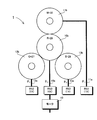
- FIG. 1 is a block diagram showing a gear mechanism 1 of a rotation angle detection device for detecting a multi-rotation absolute rotation angle according to an embodiment of the present invention.
- a main shaft 10a connected to a rotation shaft of a motor 10 is connected to a main shaft gear 10b having a tooth number R of 28, and the main shaft 10a detects a rotation angle ⁇ 0 within one rotation of the main shaft 10a.
- a resolver RS0 which is an angle detector, is attached.
- the resolver RS0 outputs an angle detection signal corresponding to a rotation angle of 0 to 360 degrees.
- the resolver RS0 is an N double angle (NX) angle detector that outputs an N period signal every time the main shaft 10a makes one rotation.
- NX N double angle
- An angle detector other than the resolver may be used.
- a rotation angle means an angle within one rotation (0 to 360 degrees)
- a rotation angle means a multi-rotation angle.
- the main shaft gear 10b is gear-coupled to the first to third counter shaft gears 11b, 12b, 13b, and the rotation of each counter shaft gear is transmitted to the first to third counter shafts 11a, 12a, 13a, respectively.
- the numbers of teeth M, Q, and S of the first to third countershaft gears 11b, 12b, and 13b are 32, 27, and 29, respectively.
- the rotation angles ⁇ 0 to ⁇ 3 of the first to third countershafts 11a, 12a, and 13a are detected by resolvers RS1 to RS3 attached to the first to third countershafts 11a, 12a, and 13a.
- the resolvers RS1 to RS3 output angle detection (value) signals corresponding to rotation angles from 0 to 360 degrees.
- the resolvers RS1 to RS3 are 1 ⁇ (1 ⁇ ) angle detectors that output a signal of one cycle each time each sub-axis rotates once, but angle detectors other than the resolver may be used.
- the number of teeth R of the main shaft gear 10b and the number of teeth M, Q, and S of the first to third countershaft gears 11b, 12b, and 13b are a is an integer of 2 or more
- the number of teeth R and M of the main shaft gear 10b and the first countershaft gear 11b are 28 and 32, respectively. Therefore, when the main shaft 10a rotates eight times, the first countershaft gear 11b The relationship between the main shaft gear 10b and the first countershaft gear 11b is restored to the original. That is, between the main shaft gear 10b and the first counter shaft gear 11b, the mutual gear position reaches the original position in a cycle of eight main shaft rotations. Further, since the number Q of teeth of the second countershaft gear 12b is 27, the relationship between the gear positions of the mainshaft gear 10b and the second countershaft gear 12b reaches the original position every time the main shaft 10a rotates 27 times. Further, since the number S of teeth of the third countershaft gear 13b is 29, when the main shaft 10a rotates 29 times, the relationship between the gear positions of the main shaft gear 10b and the third countershaft gear 13b reaches the original position.
- a periodic signal of one cycle can be calculated every 8 rotations of the main shaft 10a from the detection signals of the resolvers RS0 and RS1 that detect the rotation angles of the main shaft 10a and the first auxiliary shaft 11a, Further, a period signal of one cycle can be calculated every 27 rotations of the main shaft 10a from the detection signal of the resolver RS0 and the detection signal of the resolver RS2 that detects the rotation angle of the second counter shaft 12a. A period signal of one cycle can be calculated every 29 rotations of the main shaft 10a from the signal and the detection signal of the resolver RS3 that detects the rotation angle of the third counter shaft 12a.
- the multi-rotation absolute rotation angle of the main shaft 10a is obtained from the values of these three periodic signals.
- the range of the rotation angle at which the multi-rotation absolute rotation angle can be obtained is 6264 (8 ⁇ 27 ⁇ 29) rotation which is the least common multiple of these three periods.
- the main shaft 10a spans the range of 6264.
- a multi-rotation absolute rotation angle of 10a can be obtained.
- a calculation method for obtaining the multi-rotation absolute rotation angle ⁇ c of the main shaft 10a from the detection signal values of the resolvers RS0 to RS3 will be described.
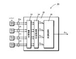
- FIG. 2 is a block diagram of the rotation angle calculation unit 20 for calculating the multi-rotation absolute rotation angle ⁇ c of the main shaft 10a.
- the rotation angles of the main shaft 10a and the first to third sub shafts 11a, 12a, and 13a are detected by resolvers RS0 to RS3, respectively, and two sinusoidal detection voltages (sin component and cosin component) that are 90 ° out of phase.
- the two detection voltages are converted from analog values into, for example, 12-bit digital values by the AD converter 23 and sent to the RD conversion arithmetic circuit 24, respectively.
- the RD conversion arithmetic circuit 24 calculates angle detection values P 0 (4X) , P 1 (1X) , P 2 (1X) , and P 3 (1X) from the received two digital values (sin component and cosin component ) , respectively. Is done.
- (4X) and (1X) attached to the symbol of the detection value indicate the values of the signals output from the quadruple angle and single angle detectors, respectively.
- the detection voltages of the resolvers RS0 to RS3 include errors due to variations in the resolvers RS0 to RS3 themselves and various factors such as magnetic, circuit, and mechanical accuracy. Signal offset correction and amplitude correction are performed, and various precision corrections such as error correction for the actual rotation angle and correction related to the detected value of each rotation axis are performed.
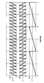
- FIG. 3 shows changes in the detected values P 0 (4X) , P 1 (1X) , P 2 (1X) , and P 3 (1X) obtained as described above with respect to the rotational speed of the main shaft 10a.
- the horizontal axis in FIG. 3 indicates the number of rotations of the main shaft 10a, and the vertical axis indicates the electrical angle of each axis corresponding to the value detected in each detected value. For ease of understanding, the vertical axis in FIG.
- the detection value P0 (4X) shown in FIG. 3A is a quadruple angle detector because the angle detector RS0 is a quadruple angle detector, so that a detection value of four periods is output every time the main shaft 10a makes one rotation.
- FIGS. 3B to 3D show changes in the rotation angle of the countershaft that has been shifted according to the gear ratio determined by the number of teeth of the main shaft gear and the number of teeth of the subshaft gear.
- the detected value P 0 (4X) is shown as a waveform that monotonously increases in the positive direction with respect to the rotation of the main shaft 10a, but the detected values P 1 (1X) , P 2 (1X) , P 3 (1X ) Monotonously decreases in the negative direction indicates that the rotation directions of the first to third countershafts 11a, 12a, and 13a are opposite to those of the main shaft 10a.
- the angle detector RS0 since the angle detector RS0 generates an N-fold angle output, the detected value P 0 (NX) of the main shaft is an angle obtained by multiplying the multi-rotation angle ⁇ 0 of the main shaft 10a by N by a basic unit amount u per rotation. Since it is the remainder divided, it can be expressed as the following equation (1).
- mod (x, a) represents a remainder operation for obtaining a remainder when x is divided by a
- a numerical value N represents a double angle number (4 in the present embodiment) of the angle detector RS0
- U represents the basic unit amount per rotation of the rotating shaft (360 ° in this embodiment).
- the multi-rotation angles ⁇ 1 , ⁇ 2 , ⁇ 3 of the first to third countershafts 11a, 12a, 13a are expressed as in the equations (2) to (4), they are detected by a single angle detector.
- the detected values P 1 (1X) , P 2 (1X) , and P 3 (1X) of the rotation angles of the first to third counter shafts are the remainders obtained by dividing the multi-rotation angles of the respective sub shafts by the basic unit amount u. Therefore, it is expressed by the following formulas (5) to (7).
- the angle detector RS0 attached to the main shaft is an N-multiple angle detector that outputs an N period signal every rotation of the main shaft
- the detected value output from this angle detector is shown in FIG.
- the output value of the angle detector is not a value that uniquely indicates the rotation angle of the spindle. Therefore, in the case of the N-fold angle detector, in order to determine the rotation angle of the main shaft, which detection region the output detection value is the value of the main shaft, in other words, the detection value belonging to what number of sawtooth wave It is necessary to determine whether it exists.
- a discriminant value is generated as follows using the difference between the rotation amounts of the main shaft and the first sub shaft. Since the detected value of the main shaft is N double angle and the detected value of the first sub shaft is 1 double angle, the detected value of the difference in the rotation amount cannot be calculated as it is. Therefore, first, as shown in the following equation (8), By obtaining a remainder obtained by dividing the result of multiplying the first counter axis detection value P 1 (1X) by N by the basic unit amount u, the detection value P 1 (NX) of the N double angle is detected from the detection value of the single angle detector. Is generated.
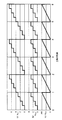
- the quadruple angle detection value P1 (4X) of the first sub-axis has a waveform shown in FIG. 4B with respect to the rotational speed of the main shaft.
- FIG. 4A shows a detection value P0 (4X) of a quadruple angle of the main shaft 11a.
- a periodic signal P 0 ((aN / M) ⁇ X) of one cycle is obtained every time the main shaft rotates M / aN from the addition result of the main axis and the first sub-axis N multiple angle.
- the periodic signal shown in FIG. 4C has a sawtooth waveform that monotonously increases every time the main shaft rotates twice. Further, the signal waveform of the detected value P0 (4X) of the main shaft 11a shown in FIG. 4A has a sawtooth waveform, but a sawtooth wave of 8 cycles within one cycle of the periodic signal of FIG. 4C. Is repeated. Therefore, the value calculated by the equation (9) is the value of the sawtooth wave at which position of the four sawtooth waves within the spindle rotation is the detected angle value PO (4X) detected by the main shaft angle detector RS0. It can be used as a discriminant value for discriminating.
- the sawtooth wave of the detected angle P 0 (NX) of the spindle is repeated M / a cycles within one cycle of the periodic signal of FIG. 4C, and the value of the periodic signal of FIG. Is divided into M / a regions, it is possible to determine in which determination region within one rotation of the main shaft the detected angle value P 0 (NX) is located.
- a stepped waveform signal is generated from the periodic signals of FIGS. 4A and 4C, and the region of the detected value P 0 (NX) is determined based on the stepped waveform.
- the stepped waveform R 0 shown in FIG. 5A can be generated from the periodic signal shown in FIG.
- the equation (10) is expressed as (a) in FIG.
- a stepped waveform R (0-7) having (M / a) -1) steps (seven steps in this embodiment ) is shown.
- This periodic signal is a signal representing a difference in rotation angle between the main shaft and the sub shaft.
- the main shaft gear and the sub shaft gear are meshed at the same position for each cycle of the periodic signal.
- the gear position of the main shaft and the sub shaft at a certain point in time is set as the initial position (the position where the main shaft rotation speed is expressed as 0). It is the figure which showed how many times it shifted
- FIG. 6A shows a periodic signal of the first countershaft representing a change in the shift angle of the gear position of the first countershaft with respect to the gear position of the main spindle, and FIG. FIG.
- FIG. 6C shows a periodic signal of the second countershaft representing a change in the shift angle of the shaft gear position
- FIG. 6C shows a change in the shift angle of the gear position of the third countershaft with respect to the gear position of the main shaft.
- the axis periodic signal is shown.
- the combinations of the values of the periodic signals are all different from the initial position of the combination in which the values of the periodic signals are all 0 until the spindle rotates and returns to the initial position again. That is, a certain combination of periodic signal values exists only during a period from the initial position to the next initial position. Therefore, if the combination of the values of the periodic signals is obtained, the rotational speed of the spindle from the initial position can be obtained.
- the rotational speed of the main spindle from the main spindle speed corresponding to the value of the periodic signal is defined as the relative rotational speed of each sub-axis within one period of each periodic signal (at the initial position, each sub-axis
- the rotational speed of the main shaft from the initial position can be obtained from the combination of the relative rotational speeds.
- the period until all the periodic signals return to the initial position is obtained by the least common multiple of the period of each periodic signal.
- the angle detector for each sub-axis is a single angle, it is necessary to convert the detection value obtained from the angle detector for the main axis into a detection value of a single angle. Accordingly, the detected value P 0 (NX) of the N-fold angle main axis and the above equation (11) are used to synthesize the detected value P 0 (1X) of the 1 ⁇ angle by the following equation (12).
- the periodic signal of the second secondary axis is obtained as a periodic signal of one period every 27 rotations of the main shaft. It is done.
- the detected value P3 (1X) of the third sub-axis is added to the detected value P0 (1X) of the main shaft, one period is obtained every time the main shaft rotates S as shown in the following equation (15).
- the periodic signal of the third counter axis is obtained with a period signal of one period every 29 rotations of the main axis. .
- the relative rotational speed of each countershaft gear is then calculated.
- the relative rotation speed is obtained by multiplying each period by the ratio of the value of the periodic signal to the basic unit quantity u because the period of the periodic signal of each sub-axis is known.
- the following equations (16), (17), and (18) are equations for calculating the relative rotational speeds m1 to m3 with respect to the first to third countershaft gears.
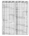
- the relationship between the multi-rotational speed n of the main shaft and the relative rotational speeds m1 to m3 of each sub-axis is calculated in advance and stored in a storage device (for example, ROM) as a reference table as shown in FIG.
- a storage device for example, ROM
- the multi-rotation rotational speed of the spindle that matches the combination of the relative rotational speeds can be obtained. For example, if the relative rotational speeds of the first to third countershaft gears are 4, 18, and 22, the rotational speed of the main shaft is 6228 from the reference table of FIG.
- the multi-rotation speed of the main shaft can be obtained (if the same gear number as in this example, it can be detected up to 216 revolutions). If the relative rotational speed of the first and second countershafts is 5, 24, the rotational speed of the main shaft is 213 from the reference table of FIG.
- the multi-rotation absolute rotation angle of the main shaft is obtained by adding the multi-rotation rotation number of the main shaft and the rotation angle within one rotation of the main shaft.
- the rotation angle within one rotation of the main shaft can be obtained by determining the region of the output signal P 0 (4X) from the quadruple-angle detector RS0 of the main shaft.
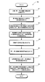
- step 81 the angle detector RS0 attached to the main shaft 10a shown in FIG. 1 attaches the quadruple angle detection value P0 (4X) to the first to third auxiliary shafts 11a, 12a, and 13a.
- the detected angle detectors RS1 to RS3 detect the detection values P 1 (1X) to P 3 (1X) of 1 ⁇ angle, respectively. These detected values show the waveforms shown in FIG. 3 with respect to the rotational speed of the spindle.
- the process proceeds to step 82, in order to determine to which determination region the main shaft detection value P 0 (4X) belongs in one rotation of the main shaft. 8), the detection value P1 (1X) of the first double angle of the first sub-axis is converted into the detection value P1 (4X) of the quadruple angle.
- the quadruple-angle detection value P0 (4X) of the main axis is added to the quadruple-angle detection value P1 (4X) to generate a discrimination value for discriminating the discrimination region.
- This discriminant value indicates the discriminant waveform shown in FIG. 4C with respect to the rotational speed of the spindle.
- the detected value detected by the spindle angle detector RS0 is determined from the discriminant value to which of the sawtooth waves shown in FIG. 4 (a) belongs to.
- the rotation angle of the main shaft is derived from the detected value.
- the determination region to which the detection value belongs is specified by the determination value. As will be described below, this determination value is further processed, and the detected angle of the main shaft is combined to obtain the rotation angle of the main shaft. be able to.
- step 84 the discriminant value obtained in step 83 is subjected to the processing shown in equation (10), thereby generating the stepped waveform value shown in FIG. Further, the stepped waveform value is substituted into the equation (11) to generate a stepped waveform value of one rotation and one period of the spindle shown in FIG. 5B. Proceeding to step 85, the stepped waveform value is substituted into equation (12) to synthesize a single-angle main axis detection value. The detected value of the main shaft of 1 ⁇ angle indicates the rotation angle of the main shaft as shown in FIG.
- the periodic signal values of the first to third sub-axes are generated in step 86 according to the equations (13) to (15). These known signal values with respect to the spindle speed are as shown in FIGS. 6 (a) to 6 (c).
- the periodic signal values of the first to third countershafts are generated, in step 87, the relative rotational speed of the first to third countershafts with respect to the main shaft is obtained by equations (16) to (18).
- a combination that matches the relative rotational speeds m1 to m3 of the first to third countershafts is searched from the reference table shown in FIG. 7, and the spindle rotational speed n for the matched combination is output.
- the spindle rotational speed n is obtained, the process proceeds to step 88, and the spindle rotational angle is added to the spindle rotational speed n to finally obtain a multi-rotation absolute rotational angle.
- the first sub-axis detection value is multiplied by N, It is necessary to satisfy.
- the accuracy required for the angle detector of the first countershaft of the present invention is the same as that of the single angle angle detector attached to the main shaft. It will be good.
Landscapes
- Physics & Mathematics (AREA)
- General Physics & Mathematics (AREA)
- Transmission And Conversion Of Sensor Element Output (AREA)
- Measurement Of Length, Angles, Or The Like Using Electric Or Magnetic Means (AREA)
Abstract
Description
主軸の回転角度を検出する主軸の角度検出器、及び、第1及び第2副軸の回転角度を検出する第1及び第2副軸の角度検出器からなる一組の角度検出器であって、主軸の角度検出器は、主軸1回転当たりN周期のN倍角検出値P0(NX)を出力し、第1及び第2副軸の角度検出器は、副軸1回転当たり1周期の1倍角検出値P1(1X),P2(1X)をそれぞれ出力する、一組の角度検出器を備え、
第1副軸ギヤの歯数は、主軸ギヤと歯数差2又はそれを越える整数aの歯数差を有し、かつ歯数差aと主軸に設けられた角度検出器の軸倍角Nの積に対して整数倍であり、また主軸ギヤと第2副軸ギヤとの歯数差は、1である関係を有するギヤ機構であって、
主軸、第1副軸、及び、第2副軸の回転角度検出値から主軸の多回転アブソリュート回転角を求める多回転角度検出装置において、
主軸の角度検出器によって検出されたN倍角検出値P0(NX)と第1副軸の角度検出器によって検出された第1副軸の1倍角検出値P1(1X)とから、第1副軸の歯数をMとすると、主軸のM/aN回転を1周期とする信号P0((aN/M)×X)を求め、信号P0((aN/M)×X)により、主軸の角度検出器によって検出されたN倍角検出値P0(NX)がN周期の内の何番目の周期の値であるかを示す判別値を得て、判別値とN倍角検出値P0(NX)とから主軸1回転当たり1周期の主軸の1倍角検出値P0(1X)を合成する主軸回転角検出手段と、
主軸の1倍角検出値P0(1X)と第1副軸の1倍角検出値P1(1X)とから主軸と第1副軸との回転数の差を示す第1副軸周期信号を生成し、さらに主軸の1倍角検出値P0(1X)と第2副軸の角度検出器によって検出された第2副軸の1倍角検出値P2(1X)とから主軸と第2副軸との回転数の差を示す第2副軸周期信号を生成し、第1副軸周期信号と第2副軸周期信号とから主軸の回転数を求める主軸回転数検出手段と、
から構成される多回転角度検出装置である。
主軸の回転角度を検出する主軸の角度検出器、及び、第1及び第2副軸の回転角度を検出する第1及び第2副軸の角度検出器からなる一組の角度検出器であって、主軸の角度検出器は、主軸1回転当たりN周期のN倍角検出値P0(NX)を出力し、第1及び第2副軸の角度検出器は、副軸1回転当たり1周期の1倍角検出値P1(1X),P2(1X)をそれぞれ出力する、一組の角度検出器を備え、
第1副軸ギヤの歯数は、主軸ギヤと歯数差2またはそれを越える整数aの歯数差を有し、かつ歯数差aと主軸に設けられた角度検出器の軸倍角Nの積に対して整数倍であり、また主軸ギヤと第2副軸ギヤの歯数差は、1である関係を有するギヤ機構であって、
主軸、第1副軸、及び、第2副軸の回転角度検出値から主軸の多回転アブソリュート回転角を求める多回転角度検出装置において、
主軸の回転角度である、主軸1回転当たりN周期のN倍角検出値P0(NX)を検出し、かつ第1及び第2副軸の回転角度である、副軸1回転当たり1周期の1倍角検出値P1(1X),P2(1X)をそれぞれ検出する段階と、
主軸の角度検出器によって検出されたN倍角検出値P0(NX)と第1副軸の角度検出器によって検出された第1副軸の1倍角検出値P1(1X)とから、第1副軸の歯数をMとすると、主軸のM/aN回転を1周期とする信号P0((aN/M)×X)を求め、信号P0((aN/M)×X)により、主軸の角度検出器によって検出されたN倍角検出値P0(NX)がN周期の内の何番目の周期の値であるかを特定するための判別値を得ることにより、主軸の1回転内の回転角度を求める段階と、
判別値とN倍角検出値P0(NX)とから主軸1回転当たり1周期の主軸の1倍角検出値P0(1X)を合成し、また主軸の1倍角検出値P0(1X)と第1副軸の1倍角検出値P1(1X)とから主軸と第1副軸との回転数の差を示す第1副軸周期信号を生成し、さらに主軸の1倍角検出値P0(1X)と第2副軸の角度検出器によって検出された第2副軸の1倍角検出値P2(1X)とから主軸と第2副軸との回転数の差を示す第2副軸周期信号を生成し、第1副軸周期信号と第2副軸周期信号とから主軸の回転数を求める段階と、
から構成される多回転角度検出方法である。


剰余計算において、mod(a,c)+mod(b,c)=mod(a+b,c)が成立するから、第1副軸のN倍角の検出値P1(NX)が求められると、その検出値に主軸検出値P0(NX)を加えると、次式(9)に示されるように、M/aN回転の周期信号が得られる。よって主軸と第1副軸N倍角の加算結果から、主軸がM/aN回転する毎に1周期の周期信号P0((aN/M)×X) が得られる。


ここで、e1≒0であるとすると、


10 モータ
11a,12a,13a 第1~第3副軸
11b,12b,13b 第1~第3副軸ギヤ
20 回転角演算部
21a,21b,21c,21d 信号線
23 AD変換器
24 RD変換演算回路
25 多回転演算回路
RS0~RS3 レゾルバ
θ0 主軸の回転角度
θ0~θ3 第1~第3副軸の回転角度
Claims (10)
- 主軸に取り付けられた主軸ギヤ、前記主軸ギヤと歯車結合する第1副軸ギヤ及び第2副軸ギヤ、及び、前記第1及び第2副軸ギヤの回転をそれぞれ伝達する第1及び第2副軸から構成され、
前記主軸の回転角度を検出する主軸の角度検出器、及び、前記第1及び第2副軸の回転角度を検出する第1及び第2副軸の角度検出器からなる一組の角度検出器であって、前記主軸の角度検出器は、主軸1回転当たりN周期のN倍角検出値P0(NX)を出力し、前記第1及び第2副軸の角度検出器は、副軸1回転当たり1周期の1倍角検出値P1(1X),P2(1X)をそれぞれ出力する、一組の角度検出器を備え、
前記第1副軸ギヤの歯数は、前記主軸ギヤと歯数差2又はそれを越える整数aの歯数差を有し、かつ歯数差aと前記主軸に設けられた角度検出器の軸倍角Nの積に対して整数倍であり、また前記主軸ギヤと前記第2副軸ギヤとの歯数差は、1である関係を有するギヤ機構であって、
前記主軸、前記第1副軸、及び、前記第2副軸の回転角度検出値から主軸の多回転アブソリュート回転角を求める多回転角度検出装置において、
前記主軸の角度検出器によって検出された前記N倍角検出値P0(NX)と前記第1副軸の角度検出器によって検出された前記第1副軸の1倍角検出値P1(1X)とから、前記第1副軸の歯数をMとすると、主軸のM/aN回転を1周期とする信号P0((aN/M)×X)を求め、前記信号P0((aN/M)×X)により、前記主軸の角度検出器によって検出されたN倍角検出値P0(NX)が前記N周期の内の何番目の周期の値であるかを示す判別値を得て、前記判別値と前記N倍角検出値P0(NX)とから主軸1回転当たり1周期の主軸の1倍角検出値P0(1X)を合成する主軸回転角検出手段と、
前記主軸の1倍角検出値P0(1X)と前記第1副軸の1倍角検出値P1(1X)とから前記主軸と前記第1副軸との回転数の差を示す第1副軸周期信号を生成し、さらに前記主軸の1倍角検出値P0(1X)と前記第2副軸の角度検出器によって検出された第2副軸の1倍角検出値P2(1X)とから前記主軸と前記第2副軸との回転数の差を示す第2副軸周期信号を生成し、前記第1副軸周期信号と前記第2副軸周期信号とから主軸の回転数を求める主軸回転数検出手段と、
から構成されることを特徴とする多回転角度検出装置。 - 前記ギヤ機構は、前記主軸ギヤと歯車結合する第3副軸ギヤ、及び、前記第3副軸ギヤの回転を伝達する第3副軸をさらに具備し、
前記角度検出器は、前記第3副軸1回転当たり1周期の前記第3副軸の1倍角検出値P3(1X)を出力し、
主軸回転数検出手段は、前記主軸の1倍角検出値P0(1X)と前記第3副軸の1倍角検出値P3(1X)とから前記主軸と前記第3副軸との回転数の差を示す第3副軸の周期信号をさらに生成し、前記第1副軸の周期信号、前記第2副軸の周期信号、及び、前記第3副軸の周期信号から主軸の回転数を求める、
ことを特徴とする請求項1記載の多回転角度検出装置。 - 前記第1及び第2副軸に加えて、さらに第3副軸を備え、前記主軸ギヤと前記第3副軸の歯数差は1であり、前記主軸の1倍角検出値P0(1X)と前記第3副軸の角度検出器によって検出された第2副軸の1倍角検出値P3(1X)とから前記主軸と前記第3副軸との回転数の差を示す第3副軸周期信号を生成し、前記主軸回転数検出手段は、前記第1副軸周期信号、前記第2副軸周期信号、及び、前記第3副軸周期信号から主軸の回転数を求めることを特徴とする請求項1記載の多回転角度検出装置。
- 第3副軸ギヤの歯数をSとすると、第2副軸ギヤの歯数がQ=R-1のとき、第3副軸ギヤの歯数はS=R+1であり、第2副軸ギヤの歯数がQ=R+1のとき、第3副軸ギヤの歯数はS=R-1である、
ことを特徴とする請求項2記載の多回転角度検出装置。 - 前記判別値P0((aN/M)×X)は、前記第1副軸の角度検出器によって検出された前記第1副軸の1倍角検出値P1(1X)をN倍した値を1周期当たりの基本単位量uで割った剰余である第1副軸のN倍角検出値P1(NX)を算出し、前記主軸のN倍角検出値P0(NX)及び前記第1副軸のN倍角検出値P1(NX)の和又は差を基本単位量uで割った剰余であることを特徴とする請求項1記載の多回転角度検出装置。
- 回転駆動源の回転を伝達する主軸に取り付けられた主軸ギヤ、前記主軸ギヤと歯車結合する第1副軸ギヤ及び第2副軸ギヤ、及び、前記第1及び第2副軸ギヤの回転をそれぞれ伝達する第1及び第2副軸から構成され
前記主軸の回転角度を検出する主軸の角度検出器、及び、前記第1及び第2副軸の回転角度を検出する第1及び第2副軸の角度検出器からなる一組の角度検出器であって、前記主軸の角度検出器は、主軸1回転当たりN周期のN倍角検出値P0(NX)を出力し、前記第1及び第2副軸の角度検出器は、副軸1回転当たり1周期の1倍角検出値P1(1X),P2(1X)をそれぞれ出力する、一組の角度検出器を備え、
前記第1副軸ギヤの歯数は、前記主軸ギヤと歯数差2またはそれを越える整数aの歯数差を有し、かつ歯数差aと前記主軸に設けられた角度検出器の軸倍角Nの積に対して整数倍であり、また前記主軸ギヤと前記第2副軸ギヤの歯数差は、1である関係を有するギヤ機構であって、
前記主軸、前記第1副軸、及び、前記第2副軸の回転角度検出値から主軸の多回転アブソリュート回転角を求める多回転角度検出装置において、
前記主軸の回転角度である、主軸1回転当たりN周期のN倍角検出値P0(NX)を検出し、かつ第1及び第2副軸の回転角度である、副軸1回転当たり1周期の1倍角検出値P1(1X),P2(1X)をそれぞれ検出する段階と、
前記主軸の角度検出器によって検出されたN倍角検出値P0(NX)と前記第1副軸の角度検出器によって検出された第1副軸の1倍角検出値P1(1X)とから、前記第1副軸の歯数をMとすると、主軸のM/aN回転を1周期とする信号P0((aN/M)×X)を求め、前記信号P0((aN/M)×X)により、前記主軸の角度検出器によって検出されたN倍角検出値P0(NX)が前記N周期の内の何番目の周期の値であるかを特定するための判別値を得ることにより、主軸の1回転内の回転角度を求める段階と、
前記判別値とN倍角検出値P0(NX)とから主軸1回転当たり1周期の主軸の1倍角検出値P0(1X)を合成し、また主軸の1倍角検出値P0(1X)と第1副軸の1倍角検出値P1(1X)とから主軸と第1副軸との回転数の差を示す第1副軸周期信号を生成し、さらに主軸の1倍角検出値P0(1X)と前記第2副軸の角度検出器によって検出された第2副軸の1倍角検出値P2(1X)とから前記主軸と前記第2副軸との回転数の差を示す第2副軸周期信号を生成し、前記第1副軸周期信号と前記第2副軸周期信号とから主軸の回転数を求める段階と、
から構成されることを特徴とする多回転角度検出方法。 - 前記ギヤ機構は、前記主軸ギヤと歯車結合する第3副軸ギヤ、及び、前記第3副軸ギヤの回転を伝達する第3副軸をさらに具備し、
前記角度検出器は、前記第3副軸1回転当たり1周期の前記第3副軸の1倍角検出値P3(1X)を出力し、
主軸回転数検出手段は、前記主軸の1倍角検出値P0(1X)と前記第3副軸の1倍角検出値P3(1X)とから前記主軸と前記第3副軸との回転数の差を示す第3副軸の周期信号をさらに生成し、前記第1副軸の周期信号、前記第2副軸の周期信号、及び、前記第3副軸の周期信号から主軸の回転数を求める、
ことを特徴とする請求項6記載の多回転角度検出方法。 - 前記第1及び第2副軸に加えて、さらに第3副軸を備え、前記主軸ギヤと前記第3副軸の歯数差は1であり、前記主軸の1倍角検出値P0(1X)と前記第3副軸の角度検出器によって検出された第2副軸の1倍角検出値P3(1X)とから前記主軸と前記第3副軸との回転数の差を示す第3副軸周期信号を生成し、前記主軸の回転数を求める段階は、前記第1副軸周期信号、前記第2副軸周期信号、及び、前記第3副軸周期信号から主軸の回転数を求める段階をさらに含むことを特徴とする請求項1記載の多回転角度検出装置。
ことを特徴とする請求項6記載の多回転角度検出方法。 - 前記第3副軸ギヤの歯数をSとすると、前記第2副軸ギヤの歯数がQ=R-1のとき、前記第3副軸ギヤの歯数はS=R+1であり、前記第2副軸ギヤの歯数がQ=R+1のとき、前記第3副軸ギヤの歯数はS=R-1である、
ことを特徴とする請求項7記載の多回転角度検出方法。 - 前記判別値P0((aN/M)×X)は、前記第1副軸の角度検出器によって検出された前記第1副軸の1倍角検出値P1(1X)をN倍した値を1周期当たりの基本単位量uで割った剰余である第1副軸のN倍角検出値P1(NX)を算出し、前記主軸のN倍角検出値P0(NX)及び前記第1副軸のN倍角検出値P1(NX)の和又は差を基本単位量uで割った剰余であることを特徴とする請求項6記載の多回転角度検出方法。
Priority Applications (5)
| Application Number | Priority Date | Filing Date | Title |
|---|---|---|---|
| ES12848893.9T ES2638332T3 (es) | 2011-11-14 | 2012-10-09 | Dispositivo de detección de ángulo de rotación absoluto de múltiples vueltas y método para la detección de ángulo de rotación absoluto |
| US13/261,897 US9528855B2 (en) | 2011-11-14 | 2012-10-09 | Multi-turn absolute rotation angle detection device and method of detecting absolute rotation angle |
| CN201280055927.4A CN103930748B (zh) | 2011-11-14 | 2012-10-09 | 多旋转绝对旋转角检测装置以及检测绝对旋转角的方法 |
| EP12848893.9A EP2789967B1 (en) | 2011-11-14 | 2012-10-09 | Multi-turn absolute rotation angle detection device and method for detecting absolute rotation angle |
| KR1020147012549A KR101942130B1 (ko) | 2011-11-14 | 2012-10-09 | 다회전 앱솔루트 회전각 검출 장치 및 앱솔루트 회전각을 검출하는 방법 |
Applications Claiming Priority (2)
| Application Number | Priority Date | Filing Date | Title |
|---|---|---|---|
| JP2011248663A JP5420624B2 (ja) | 2011-11-14 | 2011-11-14 | 多回転アブソリュート回転角検出装置及びアブソリュート回転角を検出する方法 |
| JP2011-248663 | 2011-11-14 |
Publications (1)
| Publication Number | Publication Date |
|---|---|
| WO2013073319A1 true WO2013073319A1 (ja) | 2013-05-23 |
Family
ID=48429389
Family Applications (1)
| Application Number | Title | Priority Date | Filing Date |
|---|---|---|---|
| PCT/JP2012/076093 WO2013073319A1 (ja) | 2011-11-14 | 2012-10-09 | 多回転アブソリュート回転角検出装置及びアブソリュート回転角を検出する方法 |
Country Status (7)
| Country | Link |
|---|---|
| US (1) | US9528855B2 (ja) |
| EP (1) | EP2789967B1 (ja) |
| JP (1) | JP5420624B2 (ja) |
| KR (1) | KR101942130B1 (ja) |
| CN (1) | CN103930748B (ja) |
| ES (1) | ES2638332T3 (ja) |
| WO (1) | WO2013073319A1 (ja) |
Cited By (1)
| Publication number | Priority date | Publication date | Assignee | Title |
|---|---|---|---|---|
| EP3122615A1 (en) * | 2014-03-28 | 2017-02-01 | Allied Motion Stockholm AB | Method for deriving an absolute multiturn rotational angle of a rotating shaft, and a device therefore |
Families Citing this family (12)
| Publication number | Priority date | Publication date | Assignee | Title |
|---|---|---|---|---|
| TWI500907B (zh) | 2011-01-07 | 2015-09-21 | Oriental Motor Co Ltd | 多圈旋轉絕對旋轉角之檢測裝置及該旋轉角之檢測方法 |
| JP5545769B2 (ja) | 2011-07-12 | 2014-07-09 | オリエンタルモーター株式会社 | アブソリュート変位量を算出する装置及びその方法 |
| JP6224349B2 (ja) * | 2013-05-15 | 2017-11-01 | 株式会社アイエイアイ | ステッピングモータ制御システム及びステッピングモータ制御方法 |
| GB2527819A (en) * | 2014-07-03 | 2016-01-06 | Moog Controls Ltd | Rotation transducer |
| JP7076683B2 (ja) * | 2016-06-27 | 2022-05-30 | Smc株式会社 | 位置検出装置 |
| DE102017108863A1 (de) * | 2017-04-26 | 2018-10-31 | Valeo Schalter Und Sensoren Gmbh | Ermitteln eines Drehwinkels einer Lenkwelle mittels dreier Zahnräder |
| JP6626476B2 (ja) * | 2017-07-13 | 2019-12-25 | オリエンタルモーター株式会社 | 歯車を適正位置に保持する歯車支持機構を用いる回転角検出装置 |
| KR101881559B1 (ko) * | 2017-07-19 | 2018-08-24 | 성균관대학교산학협력단 | 다회전 검출 장치 및 방법 |
| EP3459844B1 (en) * | 2017-09-25 | 2022-07-13 | Ratier-Figeac SAS | Actuator position sensor mechanism |
| US10670386B2 (en) * | 2018-04-19 | 2020-06-02 | Infineon Technologies Ag | Multi-turn counter sensor failure detection |
| JP7234577B2 (ja) * | 2018-10-31 | 2023-03-08 | セイコーエプソン株式会社 | ロボットシステム、ロボット制御方法、及びエンコーダー |
| JP7234580B2 (ja) | 2018-10-31 | 2023-03-08 | セイコーエプソン株式会社 | ロボットシステム、ロボット制御方法、及びエンコーダー |
Citations (5)
| Publication number | Priority date | Publication date | Assignee | Title |
|---|---|---|---|---|
| JPS58106691A (ja) * | 1981-12-21 | 1983-06-25 | 株式会社エスジ− | アブソリュート位置検出装置 |
| JPS60239608A (ja) * | 1984-05-15 | 1985-11-28 | Toshiba Mach Co Ltd | アブソリユ−ト位置の検知方法および検知装置 |
| JPH0421813U (ja) * | 1990-06-11 | 1992-02-24 | ||
| JP2002107178A (ja) * | 2000-09-29 | 2002-04-10 | Sanyo Denki Co Ltd | 絶対位置検出方法 |
| JP2009229396A (ja) | 2008-03-25 | 2009-10-08 | Sanyo Denki Co Ltd | バッテリレス絶対位置検出用エンコーダ |
Family Cites Families (57)
| Publication number | Priority date | Publication date | Assignee | Title |
|---|---|---|---|---|
| US4339950A (en) * | 1980-02-19 | 1982-07-20 | Lendino Nicholas C | Counting mechanism attachment for a fuel tank |
| JPS59190612A (ja) | 1983-04-13 | 1984-10-29 | Fanuc Ltd | 絶対位置検出方法 |
| JPS603099A (ja) * | 1983-06-20 | 1985-01-09 | 株式会社エスジ− | アブソリユ−ト位置検出装置 |
| JPS60239618A (ja) | 1984-05-15 | 1985-11-28 | Toshiba Mach Co Ltd | 回転体の回転量をアブソリユ−ト値で検知する方法およびその装置 |
| JPS614918A (ja) * | 1984-06-20 | 1986-01-10 | Toyota Motor Corp | レゾルバを用いた多回転の回転位置検出用アブソリユ−トセンサ |
| JPS6117913A (ja) | 1984-07-04 | 1986-01-25 | Omron Tateisi Electronics Co | ロ−タリエンコ−ダ |
| JPS61258113A (ja) * | 1985-05-10 | 1986-11-15 | Yokogawa Hewlett Packard Ltd | 位置エンコ−ダ |
| JPS63118614A (ja) * | 1986-11-07 | 1988-05-23 | Toyota Motor Corp | 多回転アブソリユ−トエンコ−ダの多回転検出装置 |
| FR2609136B1 (fr) * | 1986-12-31 | 1989-12-01 | Camara Alpha | Egalisateur de couple pour arbres contrarotatifs |
| JPS63242028A (ja) | 1987-03-30 | 1988-10-07 | Ishikawajima Harima Heavy Ind Co Ltd | 多回転絶対番地型位置検出器 |
| JPH0353114A (ja) * | 1989-07-21 | 1991-03-07 | Sony Magnescale Inc | 位置検出装置 |
| JPH0330648U (ja) * | 1989-08-04 | 1991-03-26 | ||
| JPH0371009A (ja) * | 1989-08-10 | 1991-03-26 | Mitsubishi Kasei Corp | 位置信号補正装置 |
| JPH0421813A (ja) | 1990-05-16 | 1992-01-24 | Matsushita Electric Ind Co Ltd | 光ビーム走査装置 |
| JPH04130218A (ja) * | 1990-09-20 | 1992-05-01 | Sony Magnescale Inc | 位置検出装置 |
| JPH0635932B2 (ja) | 1991-02-12 | 1994-05-11 | 株式会社エスジー | アブソリュート回転位置検出装置 |
| JPH0538243A (ja) | 1991-08-06 | 1993-02-19 | Shimano Inc | 釣り竿の糸ガイド製造方法 |
| JPH05141911A (ja) * | 1991-11-16 | 1993-06-08 | Yamaha Corp | ロータリエンコーダ |
| JPH0672187A (ja) | 1992-05-28 | 1994-03-15 | Mitsubishi Electric Corp | 自動変速機付車両用エンジン制御装置及びその制御方法 |
| US5457371A (en) * | 1993-08-17 | 1995-10-10 | Hewlett Packard Company | Binary locally-initializing incremental encoder |
| DE19506938A1 (de) * | 1995-02-28 | 1996-08-29 | Bosch Gmbh Robert | Verfahren und Vorrichtung zur Winkelmessung bei einem drehbaren Körper |
| US6026925A (en) | 1995-12-19 | 2000-02-22 | Denso Corporation | Electrically driven power assisting device |
| US5950052A (en) | 1996-09-17 | 1999-09-07 | Seiko Epson Corporation | Image forming apparatus |
| DE19855960A1 (de) * | 1998-12-04 | 2000-06-08 | Bosch Gmbh Robert | Vorrichtung und Verfahren zur Messung der Winkellage eines drehbaren Körpers |
| JP2001004405A (ja) | 1999-06-22 | 2001-01-12 | Sankyo Seiki Mfg Co Ltd | 磁気式エンコーダ装置 |
| JP3704462B2 (ja) * | 2000-09-29 | 2005-10-12 | 山洋電気株式会社 | リラクタンスレゾルバを用いた絶対位置検出器 |
| DE10048911C1 (de) * | 2000-10-02 | 2002-04-25 | Ruf Electronics Gmbh | Verfahren und Vorrichtung zur Bestimmung der Absolutposition bei Weg- und Winkelgebern |
| JP2002116057A (ja) * | 2000-10-06 | 2002-04-19 | Yaskawa Electric Corp | 多回転式絶対値エンコーダ装置 |
| EP1437575B1 (en) * | 2001-10-19 | 2006-08-30 | Kabushiki Kaisha Yaskawa Denki | Multirotation type encoder |
| AU2003223180A1 (en) | 2002-02-14 | 2003-09-04 | Bvr Technologies Company | Methods and apparatus for sensing angular position of a rotatable shaft |
| JP3967963B2 (ja) | 2002-05-29 | 2007-08-29 | オークマ株式会社 | アブソリュート変位検出装置 |
| EP1382950B1 (en) | 2002-07-10 | 2006-07-26 | JTEKT Corporation | Torque sensor |
| JP2004138606A (ja) | 2002-09-24 | 2004-05-13 | Yazaki Corp | 舵角センサ |
| JP4241012B2 (ja) * | 2002-11-25 | 2009-03-18 | パナソニック株式会社 | 回転角度検出装置 |
| DE10332413B3 (de) * | 2003-07-16 | 2005-04-28 | Ic Haus Gmbh | Positionsmessvorrichtung zum Ermitteln von Winkel- oder Längenpositionen |
| KR100610380B1 (ko) * | 2003-11-11 | 2006-08-09 | 현대모비스 주식회사 | 차량용 조향축의 절대조향각 측정방법 |
| JP2006017663A (ja) * | 2004-07-05 | 2006-01-19 | Alps Electric Co Ltd | 回転角検出装置 |
| DE502005003618D1 (de) | 2004-08-28 | 2008-05-21 | Luk Lamellen & Kupplungsbau | Verfahren zum Bestimmen der Phasenlage einer Nockenwelle einer Brennkraftmaschine |
| JP2007078459A (ja) * | 2005-09-13 | 2007-03-29 | Yaskawa Electric Corp | 多回転式絶対値エンコーダおよび回転機械 |
| DE102006006359A1 (de) * | 2006-02-11 | 2007-08-16 | Leopold Kostal Gmbh & Co. Kg | Drehwinkelsensor sowie Verfahren zum Bestimmen der absoluten Winkelstellung eines über mehrere Runden drehbaren Körpers |
| US7775129B2 (en) | 2006-04-10 | 2010-08-17 | Panasonic Corporation | Rotation angle sensor |
| JP2008039737A (ja) | 2006-08-10 | 2008-02-21 | Yaskawa Electric Corp | 多回転量算出方法、バッテリーレス多回転式絶対値エンコーダ装置およびこれを用いた減速機付アクチュエータ |
| EP2080992A4 (en) * | 2006-11-10 | 2011-06-08 | Furukawa Electric Co Ltd | APPARATUS FOR DETERMINING THE ROTATION ANGLE |
| JP4197036B2 (ja) | 2007-02-07 | 2008-12-17 | トヨタ自動車株式会社 | 動力伝達装置の制御装置 |
| JP4992516B2 (ja) * | 2007-04-02 | 2012-08-08 | パナソニック株式会社 | 回転角度検出装置 |
| JP4443585B2 (ja) * | 2007-04-17 | 2010-03-31 | 三菱電機株式会社 | 伝達比可変機構用センサシステム及びこれを用いた操舵装置 |
| DE102008011448A1 (de) * | 2008-02-27 | 2009-09-03 | Valeo Schalter Und Sensoren Gmbh | Anordnung zur Erfassung eines Drehwinkels |
| JP5167456B2 (ja) * | 2008-03-17 | 2013-03-21 | 多摩川精機株式会社 | アブソリュートセンサの多回転検出方法 |
| JP4572951B2 (ja) | 2008-04-11 | 2010-11-04 | 富士ゼロックス株式会社 | 記録材移動装置及び画像形成装置 |
| US7579829B1 (en) | 2008-07-06 | 2009-08-25 | Avago Technologies Ecbu Ip (Singapore) Pte. Ltd. | Inductive multi-turn encoder |
| US20100235054A1 (en) * | 2009-03-11 | 2010-09-16 | Kostal Of America | Steering angle sensor |
| WO2011049978A2 (en) | 2009-10-19 | 2011-04-28 | BEI Duncan Electronics | Multi-turn sensor |
| US8493572B2 (en) | 2010-05-05 | 2013-07-23 | Mitutoyo Corporation | Optical encoder having contamination and defect resistant signal processing |
| TWI500907B (zh) | 2011-01-07 | 2015-09-21 | Oriental Motor Co Ltd | 多圈旋轉絕對旋轉角之檢測裝置及該旋轉角之檢測方法 |
| DE102011106339B4 (de) * | 2011-03-04 | 2012-12-06 | Auma Riester Gmbh & Co. Kg | Messvorrichtung zur Erfassung des Absolutdrehwinkels eines rotierenden Messobjekts |
| JP5545769B2 (ja) | 2011-07-12 | 2014-07-09 | オリエンタルモーター株式会社 | アブソリュート変位量を算出する装置及びその方法 |
| JP5899412B2 (ja) * | 2011-12-09 | 2016-04-06 | パナソニックIpマネジメント株式会社 | 回転角度検出装置 |
-
2011
- 2011-11-14 JP JP2011248663A patent/JP5420624B2/ja active Active
-
2012
- 2012-10-09 US US13/261,897 patent/US9528855B2/en active Active
- 2012-10-09 CN CN201280055927.4A patent/CN103930748B/zh active Active
- 2012-10-09 WO PCT/JP2012/076093 patent/WO2013073319A1/ja active Application Filing
- 2012-10-09 ES ES12848893.9T patent/ES2638332T3/es active Active
- 2012-10-09 KR KR1020147012549A patent/KR101942130B1/ko active IP Right Grant
- 2012-10-09 EP EP12848893.9A patent/EP2789967B1/en active Active
Patent Citations (6)
| Publication number | Priority date | Publication date | Assignee | Title |
|---|---|---|---|---|
| JPS58106691A (ja) * | 1981-12-21 | 1983-06-25 | 株式会社エスジ− | アブソリュート位置検出装置 |
| JPS60239608A (ja) * | 1984-05-15 | 1985-11-28 | Toshiba Mach Co Ltd | アブソリユ−ト位置の検知方法および検知装置 |
| JPH0421813U (ja) * | 1990-06-11 | 1992-02-24 | ||
| JP2002107178A (ja) * | 2000-09-29 | 2002-04-10 | Sanyo Denki Co Ltd | 絶対位置検出方法 |
| JP3665732B2 (ja) | 2000-09-29 | 2005-06-29 | 山洋電気株式会社 | 絶対位置検出方法 |
| JP2009229396A (ja) | 2008-03-25 | 2009-10-08 | Sanyo Denki Co Ltd | バッテリレス絶対位置検出用エンコーダ |
Non-Patent Citations (1)
| Title |
|---|
| See also references of EP2789967A4 |
Cited By (2)
| Publication number | Priority date | Publication date | Assignee | Title |
|---|---|---|---|---|
| EP3122615A1 (en) * | 2014-03-28 | 2017-02-01 | Allied Motion Stockholm AB | Method for deriving an absolute multiturn rotational angle of a rotating shaft, and a device therefore |
| EP3122615A4 (en) * | 2014-03-28 | 2017-06-28 | Allied Motion Stockholm AB | Method for deriving an absolute multiturn rotational angle of a rotating shaft, and a device therefore |
Also Published As
| Publication number | Publication date |
|---|---|
| ES2638332T3 (es) | 2017-10-19 |
| US9528855B2 (en) | 2016-12-27 |
| KR20140099867A (ko) | 2014-08-13 |
| CN103930748A (zh) | 2014-07-16 |
| US20140290079A1 (en) | 2014-10-02 |
| CN103930748B (zh) | 2016-08-24 |
| KR101942130B1 (ko) | 2019-01-24 |
| JP5420624B2 (ja) | 2014-02-19 |
| EP2789967B1 (en) | 2017-05-31 |
| EP2789967A4 (en) | 2015-10-28 |
| EP2789967A1 (en) | 2014-10-15 |
| JP2013104778A (ja) | 2013-05-30 |
Similar Documents
| Publication | Publication Date | Title |
|---|---|---|
| JP5420624B2 (ja) | 多回転アブソリュート回転角検出装置及びアブソリュート回転角を検出する方法 | |
| KR101502259B1 (ko) | 다회전 앱솔루트 회전각을 검출하는 장치 및 그 회전각을 검출하는 방법 | |
| JP5341714B2 (ja) | 位相差式レゾルバ | |
| JPH0373808B2 (ja) | ||
| JP4142607B2 (ja) | バリアブルリラクタンスレゾルバ | |
| JP5256174B2 (ja) | 磁気式アブソリュートエンコーダ | |
| JP2011107048A5 (ja) | ||
| US9841947B2 (en) | Device and method for calculating absolute amount of displacement, and method for same | |
| CN110998244B (zh) | 角度检测器 | |
| JP5473984B2 (ja) | 多回転アブソリュート回転角検出装置 | |
| JP5473953B2 (ja) | 多回転アブソリュート回転角検出装置 | |
| US7119717B2 (en) | Encoder output divider and R/D converter | |
| JP6951804B2 (ja) | エンコーダ開発用信号発生装置 | |
| JP4727283B2 (ja) | 多回転絶対角度検出方法および検出装置 | |
| JP2007271372A (ja) | 回転センサ | |
| JP2004132912A (ja) | 絶対値エンコーダ | |
| RU2480707C1 (ru) | Способ измерения угла и устройство для его осуществления |
Legal Events
| Date | Code | Title | Description |
|---|---|---|---|
| 121 | Ep: the epo has been informed by wipo that ep was designated in this application |
Ref document number: 12848893 Country of ref document: EP Kind code of ref document: A1 |
|
| ENP | Entry into the national phase |
Ref document number: 20147012549 Country of ref document: KR Kind code of ref document: A |
|
| REEP | Request for entry into the european phase |
Ref document number: 2012848893 Country of ref document: EP |
|
| WWE | Wipo information: entry into national phase |
Ref document number: 2012848893 Country of ref document: EP |
|
| NENP | Non-entry into the national phase |
Ref country code: DE |
|
| WWE | Wipo information: entry into national phase |
Ref document number: 13261897 Country of ref document: US |