WO2013051449A1 - 切削インサートおよび刃先交換式切削工具 - Google Patents
切削インサートおよび刃先交換式切削工具 Download PDFInfo
- Publication number
- WO2013051449A1 WO2013051449A1 PCT/JP2012/074844 JP2012074844W WO2013051449A1 WO 2013051449 A1 WO2013051449 A1 WO 2013051449A1 JP 2012074844 W JP2012074844 W JP 2012074844W WO 2013051449 A1 WO2013051449 A1 WO 2013051449A1
- Authority
- WO
- WIPO (PCT)
- Prior art keywords
- insert
- cutting
- pair
- cutting edge
- polygonal
- Prior art date
Links
Images


Classifications
-
- B—PERFORMING OPERATIONS; TRANSPORTING
- B23—MACHINE TOOLS; METAL-WORKING NOT OTHERWISE PROVIDED FOR
- B23C—MILLING
- B23C5/00—Milling-cutters
- B23C5/02—Milling-cutters characterised by the shape of the cutter
- B23C5/10—Shank-type cutters, i.e. with an integral shaft
- B23C5/109—Shank-type cutters, i.e. with an integral shaft with removable cutting inserts
-
- B—PERFORMING OPERATIONS; TRANSPORTING
- B23—MACHINE TOOLS; METAL-WORKING NOT OTHERWISE PROVIDED FOR
- B23C—MILLING
- B23C5/00—Milling-cutters
- B23C5/16—Milling-cutters characterised by physical features other than shape
- B23C5/20—Milling-cutters characterised by physical features other than shape with removable cutter bits or teeth or cutting inserts
- B23C5/202—Plate-like cutting inserts with special form
-
- B—PERFORMING OPERATIONS; TRANSPORTING
- B23—MACHINE TOOLS; METAL-WORKING NOT OTHERWISE PROVIDED FOR
- B23B—TURNING; BORING
- B23B27/00—Tools for turning or boring machines; Tools of a similar kind in general; Accessories therefor
- B23B27/14—Cutting tools of which the bits or tips or cutting inserts are of special material
- B23B27/141—Specially shaped plate-like cutting inserts, i.e. length greater or equal to width, width greater than or equal to thickness
- B23B27/145—Specially shaped plate-like cutting inserts, i.e. length greater or equal to width, width greater than or equal to thickness characterised by having a special shape
-
- B—PERFORMING OPERATIONS; TRANSPORTING
- B23—MACHINE TOOLS; METAL-WORKING NOT OTHERWISE PROVIDED FOR
- B23B—TURNING; BORING
- B23B27/00—Tools for turning or boring machines; Tools of a similar kind in general; Accessories therefor
- B23B27/14—Cutting tools of which the bits or tips or cutting inserts are of special material
- B23B27/16—Cutting tools of which the bits or tips or cutting inserts are of special material with exchangeable cutting bits or cutting inserts, e.g. able to be clamped
- B23B27/1603—Cutting tools of which the bits or tips or cutting inserts are of special material with exchangeable cutting bits or cutting inserts, e.g. able to be clamped with specially shaped plate-like exchangeable cutting inserts, e.g. chip-breaking groove
- B23B27/1611—Cutting tools of which the bits or tips or cutting inserts are of special material with exchangeable cutting bits or cutting inserts, e.g. able to be clamped with specially shaped plate-like exchangeable cutting inserts, e.g. chip-breaking groove characterised by having a special shape
-
- B—PERFORMING OPERATIONS; TRANSPORTING
- B23—MACHINE TOOLS; METAL-WORKING NOT OTHERWISE PROVIDED FOR
- B23C—MILLING
- B23C5/00—Milling-cutters
- B23C5/16—Milling-cutters characterised by physical features other than shape
- B23C5/20—Milling-cutters characterised by physical features other than shape with removable cutter bits or teeth or cutting inserts
- B23C5/202—Plate-like cutting inserts with special form
- B23C5/205—Plate-like cutting inserts with special form characterised by chip-breakers of special form
-
- B—PERFORMING OPERATIONS; TRANSPORTING
- B23—MACHINE TOOLS; METAL-WORKING NOT OTHERWISE PROVIDED FOR
- B23C—MILLING
- B23C5/00—Milling-cutters
- B23C5/16—Milling-cutters characterised by physical features other than shape
- B23C5/20—Milling-cutters characterised by physical features other than shape with removable cutter bits or teeth or cutting inserts
- B23C5/22—Securing arrangements for bits or teeth or cutting inserts
-
- B—PERFORMING OPERATIONS; TRANSPORTING
- B23—MACHINE TOOLS; METAL-WORKING NOT OTHERWISE PROVIDED FOR
- B23B—TURNING; BORING
- B23B2200/00—Details of cutting inserts
- B23B2200/04—Overall shape
- B23B2200/0423—Irregular
-
- B—PERFORMING OPERATIONS; TRANSPORTING
- B23—MACHINE TOOLS; METAL-WORKING NOT OTHERWISE PROVIDED FOR
- B23C—MILLING
- B23C2200/00—Details of milling cutting inserts
- B23C2200/04—Overall shape
- B23C2200/0416—Irregular
-
- B—PERFORMING OPERATIONS; TRANSPORTING
- B23—MACHINE TOOLS; METAL-WORKING NOT OTHERWISE PROVIDED FOR
- B23C—MILLING
- B23C2200/00—Details of milling cutting inserts
- B23C2200/04—Overall shape
- B23C2200/0494—Rectangular
-
- B—PERFORMING OPERATIONS; TRANSPORTING
- B23—MACHINE TOOLS; METAL-WORKING NOT OTHERWISE PROVIDED FOR
- B23C—MILLING
- B23C2200/00—Details of milling cutting inserts
- B23C2200/08—Rake or top surfaces
- B23C2200/085—Rake or top surfaces discontinuous
-
- B—PERFORMING OPERATIONS; TRANSPORTING
- B23—MACHINE TOOLS; METAL-WORKING NOT OTHERWISE PROVIDED FOR
- B23C—MILLING
- B23C2200/00—Details of milling cutting inserts
- B23C2200/12—Side or flank surfaces
- B23C2200/125—Side or flank surfaces discontinuous
-
- B—PERFORMING OPERATIONS; TRANSPORTING
- B23—MACHINE TOOLS; METAL-WORKING NOT OTHERWISE PROVIDED FOR
- B23C—MILLING
- B23C2200/00—Details of milling cutting inserts
- B23C2200/12—Side or flank surfaces
- B23C2200/128—Side or flank surfaces with one or more grooves
-
- B—PERFORMING OPERATIONS; TRANSPORTING
- B23—MACHINE TOOLS; METAL-WORKING NOT OTHERWISE PROVIDED FOR
- B23C—MILLING
- B23C2200/00—Details of milling cutting inserts
- B23C2200/28—Angles
- B23C2200/284—Negative clearance angles
-
- B—PERFORMING OPERATIONS; TRANSPORTING
- B23—MACHINE TOOLS; METAL-WORKING NOT OTHERWISE PROVIDED FOR
- B23C—MILLING
- B23C2210/00—Details of milling cutters
- B23C2210/04—Angles
- B23C2210/0407—Cutting angles
- B23C2210/0442—Cutting angles positive
- B23C2210/045—Cutting angles positive axial rake angle
-
- B—PERFORMING OPERATIONS; TRANSPORTING
- B23—MACHINE TOOLS; METAL-WORKING NOT OTHERWISE PROVIDED FOR
- B23C—MILLING
- B23C2210/00—Details of milling cutters
- B23C2210/04—Angles
- B23C2210/0407—Cutting angles
- B23C2210/0442—Cutting angles positive
- B23C2210/0457—Cutting angles positive radial rake angle
-
- B—PERFORMING OPERATIONS; TRANSPORTING
- B23—MACHINE TOOLS; METAL-WORKING NOT OTHERWISE PROVIDED FOR
- B23C—MILLING
- B23C2210/00—Details of milling cutters
- B23C2210/16—Fixation of inserts or cutting bits in the tool
- B23C2210/168—Seats for cutting inserts, supports for replacable cutting bits
-
- B—PERFORMING OPERATIONS; TRANSPORTING
- B23—MACHINE TOOLS; METAL-WORKING NOT OTHERWISE PROVIDED FOR
- B23C—MILLING
- B23C2210/00—Details of milling cutters
- B23C2210/50—Cutting inserts
-
- Y—GENERAL TAGGING OF NEW TECHNOLOGICAL DEVELOPMENTS; GENERAL TAGGING OF CROSS-SECTIONAL TECHNOLOGIES SPANNING OVER SEVERAL SECTIONS OF THE IPC; TECHNICAL SUBJECTS COVERED BY FORMER USPC CROSS-REFERENCE ART COLLECTIONS [XRACs] AND DIGESTS
- Y10—TECHNICAL SUBJECTS COVERED BY FORMER USPC
- Y10T—TECHNICAL SUBJECTS COVERED BY FORMER US CLASSIFICATION
- Y10T407/00—Cutters, for shaping
- Y10T407/19—Rotary cutting tool
- Y10T407/1906—Rotary cutting tool including holder [i.e., head] having seat for inserted tool
- Y10T407/1908—Face or end mill
- Y10T407/1924—Specified tool shape
-
- Y—GENERAL TAGGING OF NEW TECHNOLOGICAL DEVELOPMENTS; GENERAL TAGGING OF CROSS-SECTIONAL TECHNOLOGIES SPANNING OVER SEVERAL SECTIONS OF THE IPC; TECHNICAL SUBJECTS COVERED BY FORMER USPC CROSS-REFERENCE ART COLLECTIONS [XRACs] AND DIGESTS
- Y10—TECHNICAL SUBJECTS COVERED BY FORMER USPC
- Y10T—TECHNICAL SUBJECTS COVERED BY FORMER US CLASSIFICATION
- Y10T407/00—Cutters, for shaping
- Y10T407/19—Rotary cutting tool
- Y10T407/1906—Rotary cutting tool including holder [i.e., head] having seat for inserted tool
- Y10T407/1934—Rotary cutting tool including holder [i.e., head] having seat for inserted tool with separate means to fasten tool to holder
-
- Y—GENERAL TAGGING OF NEW TECHNOLOGICAL DEVELOPMENTS; GENERAL TAGGING OF CROSS-SECTIONAL TECHNOLOGIES SPANNING OVER SEVERAL SECTIONS OF THE IPC; TECHNICAL SUBJECTS COVERED BY FORMER USPC CROSS-REFERENCE ART COLLECTIONS [XRACs] AND DIGESTS
- Y10—TECHNICAL SUBJECTS COVERED BY FORMER USPC
- Y10T—TECHNICAL SUBJECTS COVERED BY FORMER US CLASSIFICATION
- Y10T407/00—Cutters, for shaping
- Y10T407/23—Cutters, for shaping including tool having plural alternatively usable cutting edges
- Y10T407/235—Cutters, for shaping including tool having plural alternatively usable cutting edges with integral chip breaker, guide or deflector
-
- Y—GENERAL TAGGING OF NEW TECHNOLOGICAL DEVELOPMENTS; GENERAL TAGGING OF CROSS-SECTIONAL TECHNOLOGIES SPANNING OVER SEVERAL SECTIONS OF THE IPC; TECHNICAL SUBJECTS COVERED BY FORMER USPC CROSS-REFERENCE ART COLLECTIONS [XRACs] AND DIGESTS
- Y10—TECHNICAL SUBJECTS COVERED BY FORMER USPC
- Y10T—TECHNICAL SUBJECTS COVERED BY FORMER US CLASSIFICATION
- Y10T407/00—Cutters, for shaping
- Y10T407/24—Cutters, for shaping with chip breaker, guide or deflector
Definitions
- the present invention relates to a cutting insert that is detachably attached to a cutting edge-exchangeable cutting tool used for milling, and a cutting edge-exchangeable cutting tool to which the cutting insert is attached.
- Patent Document 1 Japanese Patent Laid-Open No. 2004-284010
- the cutting insert of patent document 1 has a rectangular plate-shaped insert main body, and the cutting edge is formed in the side ridge part of a pair of rectangular surface of an insert main body.
- the first rectangular surface is formed with a groove extending in one diagonal direction, and the inclined surface descends toward the groove from two corners located on the other diagonal line.
- the second rectangular surface is formed with a groove extending in the other diagonal direction of the first rectangular surface when viewed from the first rectangular surface side, and is aligned in the one diagonal direction.
- a slope that descends from the two corners toward the groove is formed. That is, the insert body has a shape that is twisted around two axes that are orthogonal to the center line connecting the centers of the first and second rectangular surfaces and orthogonal to the side surfaces of the four insert bodies. At the same time, they are symmetrical with respect to these axes.
- This cutting insert is detachably attached to an insert mounting seat formed on the tool body of the cutting edge exchange type cutting tool.
- the bottom surface of the insert mounting seat faces the tool rotation direction, and the shape of the bottom surface is a support surface complementary to the first rectangular surface, and the first rectangular surface is supported by the bottom surface.
- two flat wall surfaces facing the front end side and the outer peripheral side of the tool body of the insert mounting seat have two side surfaces that are flat or convexly curved of the insert body that intersect the groove of the first rectangular surface. Is supported.
- Patent Document 2 Japanese Patent Laid-Open No. 62-84904
- a flank is formed between an upper surface that is a rake surface and a lower surface that is a placement surface, and a main cutting edge is formed at an intersection between the upper surface and the flank.
- the upper surface has a twisted surface shape in which the angle formed by the reference surface parallel to the lower surface of the main cutting edge and the upper surface gradually increases from the cutting edge tip of the main cutting edge toward the rear edge of the cutting edge.
- flank is formed in a torsional surface in which the angle formed by the reference surface and the flank in the main cutting edge gradually decreases from the cutting edge tip of the main cutting edge toward the cutting edge rear end.
- the clearance angle with respect to the cutting edge is gradually increased to the positive angle side.
- the main cutting edge has a positive axial rake angle.
- the radial rake angle and clearance angle of the main cutting edge are prevented from changing from the cutting edge tip to the trailing edge.
- An appropriate rake angle and a sufficient escape amount can be obtained over the entire length of the main cutting edge.
- the blade angle of the main cutting edge can also be made substantially constant, the edge strength can be maintained over the entire length of the main cutting edge.
- the flank is a torsional surface like the cutting insert described in Patent Document 2
- the reference surface and the flank face from the cutting blade tip to the cutting blade rear end.
- the amount of protrusion of the flank face toward the outer side of the insert body on the side center portion side away from the cutting edge gradually decreases. Therefore, such a flank is overlapped on a straight line as viewed in the direction facing the rectangular surface as in the cutting insert described in Patent Document 1, and a pair of tip and rear ends are arranged on the side of the alternate corner portion of the side surface. If it extends from the cutting edge toward the center of the side as it is, the position where these flank surfaces intersect will be shifted at the center of the side.
- the present invention has been made under such a background, and in a cutting insert having an insert body having a reverse-inverted symmetrical shape with respect to a symmetry line passing through the center of at least one side surface, a pair of opposite side edges on the side surface
- the flank faces of a pair of cutting edges formed on the part are formed on this side face, the flank faces of these flank faces gradually increase toward the positive angle along the cutting edge.
- the side surface can be formed smoothly by preventing the step between the flank surfaces, and stable mounting can be achieved even when this side surface is supported by the wall surface of the insert mounting seat.
- Another object of the present invention is to provide a cutting insert capable of ensuring a sufficient escape amount over the entire length of the cutting edge.
- this invention aims at providing the blade-tip-exchange-type cutting tool which attached the said cutting insert.
- the cutting insert according to one aspect of the present invention is a cutting insert that is detachably attached to an insert mounting seat of a cutting edge exchangeable cutting tool, and includes any one of the following configurations.
- a cutting insert that is detachably attached to an insert mounting seat of a cutting edge exchangeable cutting tool, A polygonal plate-like insert body having a pair of polygonal surfaces and a plurality of side surfaces arranged around the pair of polygonal surfaces;
- the pair of polygonal surfaces is a seating surface on which the other polygonal surface is seated on the bottom surface of the insert mounting seat when one of the polygonal surfaces is a rake face, Cutting edges are respectively formed on a pair of side ridges intersecting the pair of polygonal surfaces of at least one of the side surfaces
- the insert body has a reverse-inverted symmetrical shape that is 180 ° rotationally symmetric with respect to a symmetry line passing through the center of the at least one side surface, On the at least one side surface, flank surfaces of the cutting blades when the pair of polygonal surfaces are raked surfaces are formed on the pair of polygonal surface sides, respectively.
- the cutting insert of one aspect of the present invention is a cutting insert for a cutting edge replaceable cutting tool, A first polygonal surface; a second polygonal surface facing in a direction different from the first polygonal surface; and a plurality of side surfaces arranged around the first and second polygonal surfaces.
- a polygonal plate-like insert body having; A first main cutting formed at a first side ridge portion where at least one first side surface of the plurality of side surfaces intersects the first polygonal surface, wherein the first polygonal surface is a rake surface.
- a blade A first flank formed on the first side surface across the first side ridge, A second main cutting edge formed on a second side ridge portion where the first side surface and the second polygonal surface intersect, and having the second polygonal surface as a rake surface; A second flank formed on the first side surface across the second side ridge,
- the insert body has a front-back inversion symmetrical shape that is 180 ° rotationally symmetric with respect to a symmetry line passing through the center of the first side surface,
- the first flank face has a flank angle with respect to the first main cutting edge on the positive side as it goes from the first corner part of the first polygonal face to the second corner part on the first side face.
- the second relief surface has a relief angle with respect to the second main cutting edge on the positive side as it goes from the first corner portion of the second polygonal surface to the second corner portion on the first side surface.
- the first side ridge portion protrudes outward from the second main cutting edge when the second corner portion of the first polygon surface is seen from a direction facing the first polygon surface.
- Crossing the second side ridge The second side ridge portion protrudes outward from the first main cutting edge when the second corner portion of the second polygon surface is seen from a direction facing the second polygon surface. Thus, it intersects with the first side ridge.
- each of the polygonal surfaces of the insert body has a rectangular shape
- the insert body has a pair of long side surfaces arranged on opposite sides and a pair of short side surfaces arranged on opposite sides,
- a main cutting edge is formed on each of the pair of side ridges intersecting the pair of polygonal surfaces of the pair of long side surfaces,
- the flank surfaces of these main cutting edges are formed in a torsional surface, and the pair of side ridges where the main cutting edges are formed intersect with each other when viewed from the direction facing the polygonal surface.
- the main cutting edge is a pair of a plurality of the multiple cutting edges as it goes from the one corner portion of the polygonal surface to the other corner portion when viewed from the direction facing the long side surface. It gradually recedes in the direction of the center line of the insert passing through the center of the square surface, and is inclined so as to face the polygon surface opposite to the polygon surface on which the main cutting edge is formed.
- the polygonal surface of the insert body has a parallelogram shape having a pair of obtuse corners and a pair of acute corners
- a corner blade connected to the main cutting edge is formed at the acute corner portion of each polygonal surface
- Sub-cutting blades connected to the corner blades are respectively formed on the side of the acute corner portion of the side ridge portion that intersects each short side surface of each polygonal surface
- the flank is formed in a twisted surface shape in which the flank angle with respect to the main cutting edge gradually increases toward the positive angle side from the acute corner portion toward the obtuse corner portion
- the pair of side ridges on which the main cutting edge is formed are seen from the direction facing the pair of polygonal surfaces, and the obtuse corner portion of one side ridge protrudes outside the other side ridge. Are crossed with each other.
- the auxiliary cutting edge is inserted from the center of the pair of polygonal surfaces as it is separated from the corner blade as viewed from the direction facing the short side surface. It inclines so that it may gradually recede in the direction and toward the polygonal surface side opposite to the polygonal surface on which the auxiliary cutting edge is formed.
- any one of the above (4) to (6) of the side ridge portion intersecting each short side surface of each polygonal surface, on the side opposite to the corner blade of the sub cutting blade.
- the continuous portion is a ramping blade, and the portion of the short side surface that is connected to the ramping blade is spaced apart from the ramping blade toward the polygonal surface side opposite to the polygonal surface on which the ramping blade is formed. Inclined so as to gradually recede inside the insert body.
- the insert body has a shape that is 180 ° rotationally symmetrical with respect to an insert center line passing through the centers of the pair of polygonal surfaces, Including at least a pair of the side surfaces formed with cutting edges, When the cutting blade on one side is used for cutting, a pair of contact portions formed on the other side surface is formed on the pair of side surfaces. Has been.
- the insert body has a shape that is rotationally symmetric with respect to an insert center line passing through the center of the pair of polygonal surfaces, and at least two of the side surfaces on which the cutting blades are formed. With When the cutting blade of one side surface is used for cutting, the contact portion that contacts the contact portion formed on the wall surface of the insert mounting seat is at least of the remaining side surfaces. One is formed.
- a convex curved surface portion connected to the flank face of the cutting blade is formed on the side surface, and the convex curved surface portion projects toward the insert center line direction.
- the contact portion is formed on the convex curved surface portion, and the curvature radius of the curvature formed by the convex curved surface portion is constant toward the extending direction of the cutting blade.
- tip-exchange-type cutting tool of this invention is equipped with the following structures.
- (11) A cutting edge exchangeable cutting tool, A tool body rotated about an axis, A cutting insert of any one of the above (1) to (10), which is detachably attached to the outer periphery of the tip of the tool body;
- one or more insert mounting seats to which the cutting insert is attached are formed with the bottom surface facing the tool rotation direction,
- the cutting insert has the at least one side surface directed toward the outer peripheral side of the tool body, and the one corner portion of the side ridge portion that intersects the polygonal surface that is the rake face of the side surface of the tool body.
- a positive axial rake angle is given to the cutting edge formed at the side ridge portion toward the distal end side, and the seating surface of the side surface is inside the rotation trajectory around the axis of the cutting edge. It is attached to the insert mounting seat so that the side ridge that intersects the polygonal surface is located.
- the cutting blade is configured such that when viewed from a direction facing the at least one side surface, the pair of the pair of the pair of polygonal surfaces move from the one corner portion to the other corner portion of the polygonal surface. Inclined to gradually go to the opposite polygon side in the direction of the insert center line passing through the center of the polygon plane, The cutting insert is attached to the insert mounting seat so that the insert center line is inclined toward the rear end side of the tool main body as it goes toward the polygonal surface side as a seating surface.
- the flank surfaces of these cutting blades are around the pair of polygonal surfaces. It is formed in the shape of a twisted surface in which the clearance angle with respect to the cutting edge gradually increases toward the positive angle side as it goes from one corner portion alternately in the direction to the other corner portion. Accordingly, as described above, by attaching the cutting insert so that one corner portion is directed toward the tip of the tool body and a positive axial rake angle is given to the cutting edge, similarly to the cutting insert described in Patent Document 2. It is possible to secure a sufficient amount of relief over the entire length of the cutting blade by suppressing the change in the relief angle of the cutting blade, and in part, the amount of relief is insufficient, leading to an increase in cutting resistance. Can be prevented.
- the flank is formed in a twisted surface in this way, the amount of protrusion of the flank toward the outer side of the insert body on the side central portion side away from the cutting edge is from one corner to the other corner.
- the pair of side ridge portions formed with the side cutting blades protrude from each other, and one side ridge portion protrudes outside the other side ridge portion.
- the protruding position of the flank on the side central portion side can be made substantially equal to each other on the flank of the pair of cutting blades.
- the flank surfaces of the pair of cutting blades can be smoothly continued on the side surface central portion side without causing a step or the like, and the above-described escape amount can be reliably ensured.
- stable cutting can be promoted.
- the cutting insert is attached by, for example, supporting the side surface in contact with the wall surface of the insert mounting seat, the mounting stability of the cutting insert can be improved.
- the insert body intersects with each of the pair of front and back polygonal surfaces as a reverse-inverted symmetrical shape that is 180 ° rotationally symmetrical with respect to a symmetry line passing through the center of the at least one side surface.
- each of the polygonal surfaces of the insert body has a quadrangular shape
- the insert body has a pair of long side surfaces disposed on opposite sides and a pair of short side surfaces disposed on opposite sides.
- the main cutting edges are respectively formed on the pair of side ridges intersecting the pair of polygonal surfaces of the pair of long side surfaces, and the flank surfaces of these main cutting edges are formed in a twisted surface, and
- the pair of side edges formed with the main cutting edge intersect with each other when viewed from the direction facing the polygonal surface, thereby intersecting each pair of polygonal surfaces of the pair of long side surfaces with one insert body. It is possible to use a total of four main cutting edges formed on the side ridges.
- the main cutting edge is viewed from the direction facing the long side surfaces, and the As it goes from one corner of the square surface to the other corner, it gradually recedes in the direction of the insert center line passing through the center of the pair of polygonal surfaces, opposite to the polygonal surface on which the main cutting edge is formed.
- the polygonal surface becomes a complicated twisted surface because the height of one corner and the other corner is different in the insert center line direction.
- the polygonal surface of the insert main body is formed into a quadrangular shape in this way, the polygonal surface of the rectangular shape is a parallelogram having a pair of obtuse corner portions and a pair of acute corner portions.
- a corner blade connected to the main cutting edge is formed at each of the acute corner portions, and the corner blade side of the side ridge portion intersecting each short side surface of each polygonal surface is connected to the corner blade.
- Each of the secondary auxiliary cutting edges is formed, and the flank face is formed in a twisted surface shape in which the flank angle with respect to the main cutting edge gradually increases toward the positive angle side as it goes from the acute corner portion to the obtuse corner portion,
- the pair of side ridges on which the main cutting edge is formed are seen from the direction facing the pair of polygonal surfaces, and the obtuse corner portion of one side ridge protrudes outside the other side ridge.
- Cross each other like When the secondary cutting edge used for cutting is directed to the tool body tip side of one parallelogram surface which is the rake face, the secondary cutting edge is positioned on a plane perpendicular to the axis of the tool body.
- the side ridges on the short side connected to the opposite side of the edge of the blade should be arranged so as to incline and recede toward the rear end side toward the inner peripheral side of the tool body with respect to this plane. become.
- the acute corner portion of the polygonal surface that forms a parallelogram when the main cutting edge is viewed from the direction facing the long side surface. From the obtuse corner to the insert center line passing through the center of the pair of polygonal surfaces, and gradually retreats toward the polygonal surface opposite to the polygonal surface on which the main cutting edge is formed.
- the main cutting edge is used for cutting with the acute corner facing the tool body tip side by inclining in the direction toward the tip of the tool body, while ensuring a positive axial rake angle for the main cutting edge, It is possible to attach the insert main body by inclining toward the rear end side of the tool main body toward the parallelogram surface which is the seating surface.
- the secondary cutting edge used for cutting is positioned on a plane perpendicular to the axis of the tool body in the same manner as described above, the pair of side ridges where the main cutting edge is formed as described above are parallel to each other. Even if a pair of parallelogram surfaces are configured so as to intersect each other when viewed from the direction facing the quadrilateral surface, the sharp corner portion directed to the tip side of the tool body of the parallelogram surface formed as a seating surface
- the formed secondary cutting edge can be positioned on the tool body rear end side with respect to the plane, and the secondary cutting edge can be prevented from interfering with the finished surface. Further, when performing a ramping process in which the tool main body is also fed in the axial direction to dig up the work material obliquely, the interference of the auxiliary cutting edge on the seating surface side can be prevented.
- the sub-cutting blade is also viewed from the direction facing the short side surface, and the pair of polygonal surfaces as the distance from the corner blade increases.
- the diameter of the secondary cutting edge is gradually decreased by retreating in the direction of the centerline of the insert passing through the center of the secondary cutting edge and tilting toward the polygonal surface side opposite to the polygonal surface on which the secondary cutting edge is formed.
- the rake angle can be set to a larger angle toward the positive angle side, and an increase in cutting resistance can be prevented.
- the portion of the side ridge that intersects each short side surface of each polygonal surface is connected to the opposite side of the secondary cutting edge from the corner blade as a ramping blade. It will be used for cutting. Therefore, the portion of the short side surface that is connected to the ramping blade is separated from the ramping blade toward the polygonal surface side opposite to the polygonal surface on which the ramping blade is formed.
- the short side surface connected to the ramping blade can be largely escaped from the rotation trajectory of the ramping blade around the axis of the tool body. Therefore, it is possible to avoid the short side surface portion from interfering with the work material during the ramping process, and a smoother ramping process can be performed.
- the insert body is formed into a shape that is 180 ° rotationally symmetric with respect to an insert center line passing through the center of a pair of polygonal surfaces, and includes at least a pair of the side surfaces on which the cutting blades are formed.
- a contact portion that contacts a contacted portion formed on the wall surface of the insert mounting seat is formed on the other side surface.
- the flank surfaces can be smoothly connected to each other on the other side surface to form an abutting portion having no level difference as described above.
- the insert main body can be attached more stably by securely contacting the contact portion.
- the insert main body in addition to the polygonal surface having a parallelogram shape as described above, includes the pair of pairs, such as a square shape or a regular triangle shape.
- the present invention can also be applied to one having at least two side surfaces in which the cutting edge is formed and having a shape that is rotationally symmetric with respect to an insert center line passing through the center of the polygonal surface.
- the contact portion that contacts the contacted portion formed on the wall surface of the insert mounting seat is the remaining side surface. If at least one of them is formed, the cutting blade used for cutting achieves the above-described function, and at least one of the remaining side surfaces is brought into contact with the contacted portion. By making contact, the cutting insert can be attached stably.
- the contact portion when the contact portion is formed on the side surface of the insert body as described above, a convex curved surface portion connected to the flank surface of the cutting blade is formed on the side surface, and the convex curved surface portion is formed on the insert center line. Curved in a convex curved shape that is convex toward the direction, the contact portion is formed in the convex curved surface portion, and the curvature radius of the curvature formed by the convex curved surface portion is constant toward the direction in which the cutting blade extends. By doing so, even if the abutted portion of the insert mounting seat is flat, the abutting portion can be stably abutted and the cutting insert can be securely attached, and the formation of the abutted portion can be facilitated. it can. Further, even if the contact portion is slightly inclined along the curvature of the convex curved surface portion due to a manufacturing error of the cutting insert, the contact portion can be reliably contacted with the contacted portion. it can.
- the cutting insert is attached to the cutting edge replaceable cutting tool while the side surface on which the flank is formed is formed to be smoothly continuous.
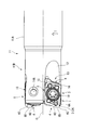
- FIG. 1 is a perspective view showing an embodiment of a cutting edge exchangeable cutting tool of the present invention to which a cutting insert according to a first embodiment is attached. It is an enlarged plan view of the front-end
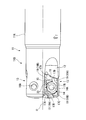
- FIG. 6 is an enlarged front view of the embodiment shown in FIG. 5.
- FIG. 10 is an enlarged plan view of the distal end portion of the tool body shown in FIG. 9. It is an enlarged side view of the front-end
- FIG. 10 is an enlarged front view of the tool body shown in FIG. 9.
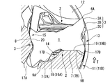
- 8 is an enlarged front view of the embodiment shown in FIG. 8 as viewed from a direction perpendicular to an imaginary straight line on the insert side on a polygonal surface (parallelogram surface) which is a seating surface of one cutting insert (the right cutting insert in FIG. 8).
- FIG. FIG. 14 is a partial enlarged cross-sectional view taken along the line AA in FIG.
- FIG. 14 is a partial enlarged cross-sectional view taken along the line BB in FIG. 13 (a cross-sectional view orthogonal to the insert-side imaginary straight line and the mounting seat-side imaginary straight line of the parallelogram surface as the seating surface).
- It is an AA partial expanded sectional view in FIG.
- It is BB partial expanded sectional view in FIG.
- FIG. 18 is an enlarged cross-sectional view of the main cutting edge in FIG. 17 (the upper right main cutting edge in FIG. 17). It is the figure which piled up the section of the insert main part shown in Drawing 16 and Drawing 17.
- FIG. 14 is a partial enlarged cross-sectional view taken along the line BB in FIG. 13 (a cross-sectional view orthogonal to the insert-side imaginary straight line and the mounting seat-side imaginary straight line of the parallelogram surface as the seating surface).
- It is an AA partial expanded sectional view in FIG.
- It is BB partial expanded sectional view in FIG.
- FIG. 18 is an enlarged cross-sectional view of
- FIG. 20 is a view for explaining the rake angle and clearance angle of the main cutting edge in FIG. 19 (enlarged view of portion A in FIG. 19). It is sectional drawing which shows the modification of the flank of the main cutting blade shown in FIG. It is sectional drawing which shows the other modification of the flank of the main cutting blade shown in FIG. It is the side view which looked at embodiment shown in FIG. 1 from the arrow X direction in FIG. It is a top view which shows the outline of a pair of polygonal surface of embodiment shown in FIG. It is the schematic which shows the flank formed in one long side surface of embodiment shown in FIG. It is a top view which shows the outline at the time of forming a pair of polygonal surface without twisting with respect to embodiment shown in FIG.
- FIG. 33 is a side view of the embodiment shown in FIG. 32. It is a front view of embodiment shown in FIG.
- FIGS. 5 to 8 show the cutting edge exchangeable cutting tool of the present invention to which the cutting insert of the first embodiment is attached.
- 1 shows the appearance of one embodiment.
- FIGS. 9 to 12 show the external appearance of the tool body in a state in which the cutting insert is removed in the cutting edge replacement type cutting tool of this embodiment.
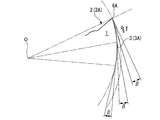
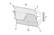
- the cutting insert of this embodiment has an insert body 1.
- the insert body 1 is made of a hard material selected from cemented carbide, cermet, surface-coated cemented carbide, surface-coated cermet, etc., and has a polygonal plate shape, more specifically, a plate shape in which the polygonal surface forms a square shape, Specifically, a pair of parallelogram surfaces 2 in which a polygonal surface is formed in a plate shape having a substantially parallelogram shape, and a pair of acute corner portions A and obtuse corner portions B are alternately arranged in the circumferential direction; A pair of long side surfaces 3 and a pair of short side surfaces 4 that connect the side ridges are provided.
- first polygon surface 2 When one parallelogram surface (first polygon surface) 2 is a rake surface, the other parallelogram surface (second polygon surface) 2 is seated on the bottom surface of the insert mounting seat described later. When the other parallelogram surface 2 is the rake face, the other parallelogram surface 2 is the seating surface.
- the insert main body 1 of this example has a parallelogram-shaped polygonal surface, the polygonal surface may be a rectangle. In that case, both end portions of one diagonal line may be regarded as an obtuse corner portion of the parallelogram surface 2 and both end portions of the other diagonal line may be regarded as acute corner portions.
- the mounting hole 5 is formed in the insert body 1.
- the mounting hole 5 has a circular cross section around an insert center line C connecting the centers of the pair of parallelogram surfaces 2, and the insert body in the insert center line C direction (the thickness direction of the insert body 1). 1 is penetrated.
- an annular reduced diameter portion 5 ⁇ / b> A is formed in the center portion of the mounting hole 5.
- the diameter-reduced portion 5A has a cylindrical surface centered on the insert center line C having a narrow center portion in the insert center line C direction, and cross sections along the insert center line C are convex curves on both sides of the cylindrical surface. A portion having a shape is formed.
- the insert body 1 includes a symmetry line (not shown) extending perpendicularly to the insert center line C and substantially parallel to the long side surface 3 at the center of the insert body 1 in the direction of the insert center line C, and the symmetry line and the insert center line C. And a symmetry line N passing through the center of the long side surface 3 perpendicularly to each other, each is formed in a 180 ° rotationally symmetric shape. That is, the insert body 1 has a front / back inversion symmetrical shape. The insert body 1 is also formed in a 180 ° rotationally symmetric shape with respect to the insert center line C. Therefore, as shown in FIG.
- the other parallelogram surface 2 when viewed from the direction facing one parallelogram surface 2, the other parallelogram surface 2 is located at the acute corner portion A side of the one parallelogram surface 2.
- the obtuse corner portion B of the other parallelogram surface 2 is positioned at the obtuse corner portion B side of the one parallelogram surface 2.
- a main cutting edge (first main cutting edge) 6A as a cutting edge in the present embodiment is formed on one long side ridge (first side ridge) of one parallelogram surface 2, and the other A main cutting edge (second main cutting edge) 6 ⁇ / b> A as a cutting edge in this embodiment is formed on one long side ridge (second side ridge) of the parallelogram surface 2.
- a main cutting edge (first main cutting edge) 6A as a cutting edge in the present embodiment is also formed on the other long side ridge part (first side ridge part) of the other parallelogram surface 2.
- a main cutting edge (second main cutting edge) 6 ⁇ / b> A as a cutting edge in the present embodiment is also formed on the other long side ridge (second side ridge) of the parallelogram surface 2.
- the main cutting edge 6A is substantially straight when viewed from the direction facing the quadrilateral plane 2 parallel to the insert center line C direction.
- a minor cutting edge 6B is formed on one short side ridge portion of one parallelogram surface 2 on the acute corner portion A (first corner portion) side, and the other of the one of the parallelogram surfaces 2 is formed.
- the auxiliary cutting edge 6B is also formed on the acute corner portion A (first corner portion) side of the short side ridge portion.
- a secondary cutting edge 6B is formed on the acute corner portion A (first corner portion) side of one short side ridge portion of the other parallelogram surface 2, and the other parallelogram surface 2 has the other side.
- the auxiliary cutting edge 6B is also formed on the acute corner portion A (first corner portion) side of the short side ridge portion.
- the auxiliary cutting edge 6B When viewed from the direction facing the parallelogram surface 2 in the direction of the insert center line C, the auxiliary cutting edge 6B has a linear shape extending in a direction slightly intersecting the obtuse angle with respect to the main cutting edge 6A.
- the intersecting ridge line portion between the long side surface 3 and the short side surface 4 is chamfered in a cross-sectional arc shape over the entire length, and the acute corner portion A of the side ridge portions of the parallelogram surface 2 has the above-mentioned cross-sectional circle.
- a corner blade 6 ⁇ / b> C is formed in the arc chamfered portion.
- the corner blade 6C has a substantially 1 ⁇ 4 arc shape when viewed from the direction parallel to the quadrilateral surface 2 parallel to the insert center line C direction, and is continuous with the main cutting edge 6A and the auxiliary cutting edge 6B.
- the obtuse corner portion B of the parallelogram surface 2 is also chamfered in an arc shape.
- the main cutting edge 6 ⁇ / b> A is spaced apart from the corner edge 6 ⁇ / b> C (acute corner portion A) toward the obtuse corner portion B as shown in FIG.
- the main cutting edge 6A is substantially linear with a substantially constant inclination angle so as to face the parallelogram surface 2 side opposite to the parallelogram surface 2 formed on the side ridge. It is tilted. Therefore, as shown in FIG. 3, the long side surface 3 also has a substantially parallelogram shape, and is inclined in the direction of the insert center line C toward the longitudinal direction (vertical direction in FIG. 3).
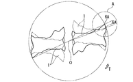
- the pair of main cutting edges 6 ⁇ / b> A formed on one parallelogram surface 2 are arranged so as to intersect in an X shape.
- the secondary cutting edge 6B is gradually retracted in the direction of the insert center line C as it is separated from the corner blade 6C (acute corner portion A). It is inclined substantially linearly at a substantially constant inclination angle so as to face the parallelogram surface 2 on the side opposite to the parallelogram surface 2 on which the cutting edge 6B is formed.
- the corner blade 6C has a protruding end in the direction of the insert center line C at a position that bisects the 1 ⁇ 4 arc in a side view, and is continuous so as to contact the main cutting edge 6A and the auxiliary cutting edge 6B. It is a convex curve.
- the portion other than the secondary cutting edge 6B of the intersecting ridge line portion between the parallelogram surface 2 and the short side surface 4 is viewed from the direction facing the parallelogram surface 2 as shown in FIG. 6B and an obtuse angle, and it is made into the substantially straight line shape which touches the circular-arc-shaped chamfer formed in the obtuse angle corner part B of the parallelogram surface 2.
- this portion has a steeper inclination than the inclination angle formed by the auxiliary cutting edge 6 ⁇ / b> B in the same side view as it is separated from the auxiliary cutting edge 6 ⁇ / b> B, as shown in FIG. 4.
- the portion of the auxiliary cutting blade 6B that is connected to the opposite side of the corner blade 6C is a ramping blade 6D.
- a positive rake surface 2A is formed inside the main cutting edge 6A, the auxiliary cutting edge 6B, the corner edge 6C, and the ramping edge 6D.
- the positive rake face 2A is formed so as to gradually retreat in the direction of the insert center line C as it goes inward of the parallelogram face 2.
- the positive rake face 2A is formed with a substantially constant width over the entire circumference of the parallelogram face 2.
- the inclination angle of the positive rake face 2A with respect to the direction perpendicular to the insert center line C Is substantially constant.
- the inclination angle of the positive rake surface 2A with respect to the direction perpendicular to the insert center line C is:
- the distance from the corner blade 6C (acute corner portion A) is gradually decreased along the main cutting edge 6A. That is, the positive rake face 2A has a twisted surface shape with the rake angle gradually decreasing from the acute corner portion A side to the obtuse corner portion B side with respect to the main cutting edge 6A.
- a pair of contact surfaces 7 are formed between the positive rake surface 2 A and the opening of the mounting hole 5.
- the pair of contact surfaces 7 are arranged along the pair of insert side virtual planes P in each parallelogram surface 2, and the pair of insert side virtual planes P
- Each of the parallelogram surfaces 2 extending on the parallelogram surface 2 on which the contact surface 7 is formed includes one insert-side virtual straight line L, and from the direction along the insert-side virtual straight line L. As shown in FIG. 3, they are arranged in a direction intersecting with each other in an X shape with the insert-side virtual straight line L as an intersection.
- the pair of insert-side virtual planes P is divided into two so that one plane including the insert-side virtual straight line L has a dividing line that intersects with the insert-side virtual straight line L.
- Two planes are twisted around the imaginary line L on the insert side, and an angle is formed so as to intersect in an X shape when viewed in the direction of the imaginary line L of the insert side.
- a pair of contact surface 7 is arrange
- the insert side virtual straight line L of the insert side virtual plane P on which the pair of contact surfaces 7 are disposed extends.
- An abutting portion 8 is formed on one side surface with respect to one parallelogram surface 2 facing the direction, and this abutting portion 8 is formed on one wall surface of an insert mounting seat described later. It can be brought into contact with the contacted portion.
- the insert-side virtual straight line L extends between the pair of long side surfaces 3 when viewed from the direction facing the parallelogram surface 2.
- the long side surface 3 is formed.
- the insert body 1 since the insert body 1 has a 180 ° rotationally symmetric shape with respect to the insert center line C, the pair of insert-side virtual straight lines L respectively extending on the pair of parallelogram surfaces 2 are the center of the insert. It will be orthogonal to line C. And in the cutting insert of this embodiment formed in 180 degree
- the insert-side virtual straight line L of each parallelogram surface 2 is orthogonal to the long side surface 3 when viewed from the direction facing the parallelogram surface 2 along the insert center line C. It extends in the direction to do. Accordingly, these imaginary straight lines L on the insert side have the symmetry line N passing through the center of the long side surface 3 as shown in FIG. 2 when viewed from the direction facing the parallelogram surface 2 along the insert center line C. Will overlap.
- the pair of insert side virtual planes P on which the pair of contact surfaces 7 are disposed are each a pair of main cutting edges formed on each parallelogram surface 2 at the intersection ridge line portion with the long side surface 3. It arrange
- the X-shaped inclination direction formed by the pair of insert-side virtual planes P when viewed in the direction of the insert-side virtual straight line L is the direction in which the main cutting edge 6A on the side adjacent to each insert-side virtual plane P faces the long side surface 3. The direction is the same as the X-shape when viewed from the top.
- each of the pair of contact surfaces 7 in the present embodiment is formed by a plurality of (two in the present embodiment) contact surface portions 7A and 7B which are disposed along the pair of insert-side virtual planes P. It is configured.
- these contact surface portions 7A and 7B are formed between the pair of acute corner portions A of the parallelogram surface 2 and the obtuse corner portion between the substantially inner edge of the positive rake face 2A and the opening of the mounting hole 5. It is arranged on the B side. That is, in each of the pair of insert-side virtual planes P, the contact surface portions 7A and 7B are disposed on both sides of the insert-side virtual straight line L, so that the pair of contact surfaces 7 also have the insert-side virtual straight line L respectively. It extends across both sides of the bridge.
- the first contact surface portion 7A arranged on the side protruding in the direction of the X-shaped insert center line C formed by the pair of insert-side virtual planes P as viewed in the insert-side virtual straight line L direction is the first convex portion. It is formed on 9A.
- the first convex portion 9A is formed on the acute corner portion A side of the parallelogram surface 2 and protrudes from the inner edge of the positive rake face 2A in the acute corner portion A.
- the first convex portion 9 ⁇ / b> A is viewed from the parallelogram surface 2
- the mounting hole 5 is formed from the inside of the end portion of the sub cutting edge 6 ⁇ / b> B opposite to the corner blade 6 ⁇ / b> C. It is formed so as to extend substantially in parallel with the main cutting edge 6A connected to the acute corner portion A on the side where the first convex portions 9A are formed over the opening.
- both end portions of the first convex portion 9A in the direction substantially parallel to the main cutting edge 6A are formed in a shape in which the truncated cone is halved along the center line, and between the both end portions,
- the first convex portion 9A has a cross section orthogonal to the direction in which the first convex portion 9A extends so as to form a substantially isosceles trapezoid as shown in FIGS. 16 and 17, and both ends and the surface are smoothly connected. It is formed as follows.
- the protruding end surface portion of the first convex portion 9A in the direction of the insert center line C is the first contact surface portion 7A, and the first contact surface portion 7A is located on the insert-side virtual plane P.
- a cross section perpendicular to the direction in which the first convex portion 9A extends forms a convex curve having a large radius of curvature, and the protruding end of the convex curve follows the insert-side virtual plane P. It has a curved shape.
- the second contact surface portion 7B arranged on the side retreating in the insert center line C direction in the X shape is formed on the second convex portion 9B.
- the second convex portion 9 ⁇ / b> B protrudes from the inner edge of the positive rake face 2 ⁇ / b> A in the obtuse corner portion B on the obtuse corner portion B side of the parallelogram surface 2.
- the protruding amount of the second convex portion 9B with respect to the inner edge of the positive rake face 2A at the obtuse corner portion B is made smaller than the protruding amount of the first convex portion 9A with respect to the inner edge of the positive rake face 2A. ing.
- the second convex portion 9B extends in a diagonal direction connecting the pair of obtuse corner portions B of the parallelogram surface 2 when viewed from the direction facing the parallelogram surface 2.
- the cross section orthogonal to the direction in which the first convex portion 9A extends is flattened in the direction of the insert center line C as compared to the first convex portion 9A as shown in FIGS. It has an isosceles trapezoidal shape, and the flat protruding end surface of the second convex portion 9B is the second contact surface portion 7B.
- the second contact surface portion 7B and the second convex portion 9B have a trapezoidal shape that gradually becomes wider toward the inside in the diagonal direction as viewed from the direction facing the parallelogram surface 2. .
- first and second contact surface portions 7A and 7B formed on the first and second convex portions 9A and 9B are arranged on the adjacent sides as shown in FIGS.
- Each pair of contact surfaces 7 is configured to be arranged on each one of the insert side virtual planes P along the cutting edge 6A.
- the opening of the attachment hole 5 is formed at an intermediate position between the first and second contact surface portions 7A and 7B in the insert center line C direction, and among these, the second contact surface portion 7B and the attachment hole 5 are formed. Between the opening, a boss 2B having a substantially conical outer shape centering on the insert center line C is formed.
- the inclination angles ⁇ of the pair of insert-side virtual planes P when viewed from the direction along the insert-side virtual straight line L are mutually relative to the plane orthogonal to the insert center line C. Equally, the range is 5 ° to 25 °.
- the inclination angle with respect to the plane perpendicular to the insert center line C of the main cutting edge 6A on the side where the pair of insert-side imaginary planes P is adjacent is also 5 ° to The range is 25 °.
- the inclination angle of the main cutting edge 6A may or may not be equal to the inclination angle ⁇ of the insert-side virtual plane P. In the present embodiment, the inclination angle is slightly different.
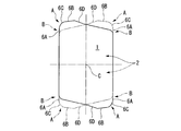
- flank of the main cutting edge 6A (the main flank, the first and second flank in the present invention) is formed on the long side surface 3 of the insert body 1 where the contact portion 8 is formed as described above.
- a flank (sub flank) of the auxiliary cutting edge 6B is formed on the short side surface 4.
- the short side surface 4 includes a pair of parallelogram surfaces 2 in order from the sub cutting edge 6B of one parallelogram surface 2 to the other parallelogram surface 2 side in order. 4A, the 2nd sub relief surface 4B, and the negative surface 4C are formed.
- a ramping flank 4D is formed at a portion of the short side surface 4 that is continuous with the ramping blade 6D.
- the first sub-flank 4A is connected to the sub-cutting edge 6B of one parallelogram surface 2 and is inclined so as to gradually protrude toward the outside of the insert body 1 gradually toward the other parallelogram surface 2 side. Yes.
- the second sub-flank 4B is formed so as to be steeper than the slope of the first sub-flank 4A toward the other side of the parallelogram surface 2, and gradually retreats to the inside of the insert body 1. ing.
- the first and second sub-flanks 4A and 4B are formed to have substantially convex curved surfaces as shown in FIG.
- the first auxiliary flank 4A may extend parallel to the insert center line C.
- the negative surface 4C extends substantially parallel to the insert center line C from the second secondary relief surface 4B, and the first and second secondary relief surfaces 4A, 4B extend from the secondary cutting edge 6B of the other parallelogram surface 2.
- a ramping relief surface 4D connected to the ramping blade 6D of the other parallelogram surface 2 is also intersected.
- this ramping flank 4D also extends in parallel with the insert center line C in this embodiment, and the two ramping flank 4Ds formed on one short side surface 4 and the ramping flank 4D are connected to each other.
- the blades 6D have a concave V shape as shown in FIG. 2 when viewed from the direction facing the parallelogram surface 2.
- the intersecting ridge line portion between the first auxiliary flank 4A and the second auxiliary flank 4B extends substantially parallel to the auxiliary cutting edge 6B.
- the intersecting ridge line portion between the second sub-flank 4B and the negative surface 4C extends in a direction perpendicular to the insert center line C.
- the intersecting ridge line portion between the first auxiliary flank 4A and the ramping flank 4D extends substantially parallel to the insert center line C from the intersection of the auxiliary cutting edge 6B and the ramping blade 6D.
- the intersecting ridge line portion between the surfaces 4C and the intersecting ridge line portion between the negative surface 4C and the ramping relief surface 4D extend along the insert center line C in a straight line. Furthermore, the intersection ridge line portion between the second auxiliary flank 4B and the ramping flank surface 4D is formed at both ends of the intersection ridge line portion between the negative surfaces 4C and the intersection ridge line portion between the first auxiliary flank surface 4A and the ramping flank surface 4D. It extends obliquely with respect to the insert center line C in the same side view so as to connect the end portion.
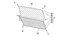
- the long side surface 3 has a pair of main parts described above that are connected to the main cutting edges 6A of the pair of parallelogram surfaces 2 in order from the pair of parallelogram surfaces 2 toward the center portion in the direction of the insert center line C, respectively.
- the convex curved surface portion 3B is curved so as to form a convex curved surface that is convex to the outside of the insert body 1, and the concave curved surface portion 3C is concaved to the inside of the insert main body 1 on the contrary. Curved into a concave curved surface.
- the said contact part 8 in this embodiment is formed in the said convex-curved surface part 3B among the long side surfaces 3.
- FIG. 2 when one parallelogram surface 2 is a rake face and one main cutting edge 6A is used for cutting among a pair of main cutting edges 6A formed on the long side ridge, one long Among the pair of convex curved surface portions 3B formed on the side surface 3, in the one parallelogram surface 2, the other main cutting edge 6A opposite to the one main cutting edge 6A is interposed via the main flank 3A.
- the abutting portions 8 formed on the convex curved surface portions 3B that are continuous with each other are brought into abutment with the abutted portions described later.
- the width of the main flank 3A in the direction of the insert center line C is such that the main cutting edge 6A extends along the main cutting edge 6A.
- the width in the direction of the insert center line C of the pair of convex curved surface portions 3B is gradually reduced from the acute corner portion A of 6A toward the obtuse corner portion B.
- the main cutting edge 6A is made to gradually increase gradually from the acute corner portion A toward the obtuse corner portion B.
- the width of the one concave curved surface portion 3C in the direction of the insert center line C is constant.
- the main flank 3A, the convex curved surface portion 3B, and the concave curved surface portion 3C are inclined in the direction of the insert center line C in the longitudinal direction of the long side surface 3 as with the long side surface 3 as a whole. It should be noted that the curvature radius of curvature formed by the convex curved surface portion 3B and the curvature radius of curvature formed by the concave curved surface portion 3C are respectively constant toward the longitudinal direction of the long side surface 3 that is the direction in which the main cutting edge 6A extends.
- the convex curved surface portion 3B and the concave curved surface portion 3C are formed in a convex and concave cylindrical surface shape.
- the main flank 3A is inserted as the distance from the main cutting edge 6A increases in the cross section perpendicular to the main cutting edge 6A when viewed from the direction facing the parallelogram surface 2 along the insert center line C. It is formed to be inclined so as to slightly protrude toward the outside of the main body 1, except that the inclination angle with respect to the direction of the insert center line C is separated from the corner blade 6C (acute corner portion A) along the main cutting edge 6A. It is made to become small gradually.
- the convex curved surface portion 3B has a convex curved surface shape that protrudes outward from the main flank 3A toward the center of the insert center line C in the direction of the insert center line C and then inward.
- a pair of parallelogram surface 2 is insert centerline.
- the main cutting edge 6A is formed so as to be twisted by being slightly rotated around the C, so that the main cutting edge 6A intersects with a pair of parallelogram surfaces 2 being shifted. More specifically, as shown in FIG. 24, when viewed from the direction facing the parallelogram surface 2, the pair of parallelogram surfaces 2 are mutually connected to the main cutting on the acute corner portion A side of one parallelogram surface 2.
- the long side ridges on which the main cutting edge 6A is formed intersect each other so that the obtuse corner B of the other parallelogram surface 2 slightly protrudes from the blade 6A to the outside of the insert body 1. That is, the main cutting edge (first main cutting edge) 6A has an obtuse corner portion (second corner portion) B of the parallelogram surface 2 as viewed from the direction facing the one parallelogram surface 2. It intersects with the main cutting edge (second main cutting edge) 6A so as to protrude outside the main cutting edge (second main cutting edge) 6A of the other parallelogram surface 2.
- the main cutting edge (second main cutting edge) 6A has an obtuse corner portion (second corner portion) B of the parallelogram surface 2 as viewed from the direction facing the other parallelogram surface 2.
- the main cutting edge (first main cutting edge) 6A intersects with the main cutting edge (first main cutting edge) 6A so as to protrude outward from the main cutting edge (first main cutting edge) 6A of one parallelogram surface 2.
- the main flank 3A itself includes a first main flank 3a having a convex arc shape connected to the main cutting edge 6A, and the center side of the first main flank 3a in the insert center line C direction side. And a second main flank 3b having a linear cross section.
- the width of the first main flank 3a in the direction of the insert center line C is substantially constant, and the width of the second main flank 3b in the direction of the insert center line C is changed from the acute corner portion A to the obtuse corner portion B.
- the width of the entire main flank 3A is reduced from the acute corner portion A toward the obtuse corner portion B by gradually decreasing as it goes.
- any of the main flank 3A on the main flank 3A as shown in FIG. may be a so-called eccentric flank in which the clearance angle ⁇ is constant even at the position.
- the main flank 3A may be a so-called concave flank having a concave curve shape formed by the outer peripheral surface of the disc type grindstone G as shown by a two-dot chain line in FIG. It may be a straight second surface forming a straight line shown by a solid line in FIG.
- first flank 3A is orthogonal to the main cutting edge (first main cutting edge) 6A when viewed from the direction facing one parallelogram surface 2 along the insert center line C. In the cross section to be inclined, it is inclined toward the inside of the insert body 1 as it is separated from the main cutting edge 6A.
- 6C acute corner portion A
- 6C may be formed in a twisted surface shape that gradually increases as it moves away from the main cutting edge 6A so that the clearance angle with respect to the main cutting edge 6A gradually increases toward the positive angle side.
- a twisted surface in which the clearance angle gradually increases toward the positive angle side within a range of angles may be used.
- one main flank 3A is inclined so as to protrude outward from the insert body 1 as it is separated from the main cutting edge 6A on the acute corner portion A side, and the flank angle toward the obtuse corner portion B is a positive angle.
- the twisted surface On the obtuse corner portion B side, the twisted surface may be inclined toward the inner side of the insert body 1 as the distance from the main cutting edge 6A increases.
- the other main flank (second flank) 3A has a main cutting edge (second main cutting edge) 6A as viewed from the direction facing the other parallelogram 2 along the insert center line C. In the cross section orthogonal to the main cutting edge 6A, it is inclined to the inside of the insert body 1 as it is separated from the main cutting edge 6A.
- the twisted surface shape that is gradually increased as it is separated from the corner blade 6C (acute corner portion A), and the clearance angle with respect to the main cutting edge 6A is gradually increased to the positive angle side, That is, it may be a twisted surface in which the clearance angle gradually increases toward the positive angle within the range of the positive angle.
- the other main flank 3A is inclined so as to protrude to the outside of the insert body 1 as it is separated from the main cutting edge 6A on the acute corner portion A side, and the flank angle toward the obtuse corner portion B is a positive angle.
- the twisted surface On the obtuse corner portion B side, the twisted surface may be inclined toward the inner side of the insert body 1 as the distance from the main cutting edge 6A increases.
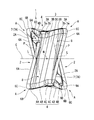
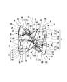
- FIGS. 5 to 8 show a cutting edge-replaceable cutting tool according to an embodiment of the present invention in which the cutting insert is detachably attached.
- FIGS. 9 to 12 show a cutting insert from this cutting-edge replaceable cutting tool. The removed state is shown.
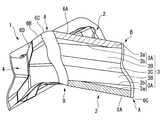
- This cutting edge exchange type cutting tool is a cutting edge exchange type cutting tool, particularly an end mill, and has a tool body 11.
- the tool body 11 is formed of a steel material or the like and has a multi-stage columnar shape with the axis O as the center.
- the rear end portion of the tool body 11 (the upper portion in FIGS. 5 and 9; the right portion in FIGS. 6, 7 and 10, and 11) is the shank portion 11A, and the tip portion is the cutting edge portion 11B. ing.
- the shank portion 11A is held by the main spindle of the machine tool, and the tool body 11 is rotated in the tool rotation direction T around the axis O while intersecting the axis O (normally) Is fed in the direction perpendicular to the axis O), the workpiece is cut by the main cutting edge 6A, the auxiliary cutting edge 6B, and the corner cutting edge 6C of the cutting insert attached to the cutting edge portion 11B.
- a plurality of chip pockets 12 are formed at equal intervals in the circumferential direction, that is, on opposite sides of the axis O. .
- the tip pocket 12 opens to the front end surface of the cutting edge portion 11B, that is, the front end surface of the tool body 11, and extends to the rear end side.
- an insert mounting seat 13 to which the cutting insert is mounted is formed on the wall surface of the tip pocket 12 facing the tool rotation direction T side. As shown in FIGS. 9 to 12, the insert mounting seat 13 opens to the front end surface and the outer peripheral surface of the cutting edge portion 11 ⁇ / b> B, and is recessed one step from the wall surface of the chip pocket 12 to the rear side in the tool rotation direction T. Is formed.
- the insert mounting seat 13 has a bottom surface 14 facing the tool rotation direction T, a wall surface 15 facing the outer peripheral side of the tool body 11, and a wall surface 16 facing the tip side of the tool body 11.
- the other parallelogram surface 2 serves as a seating surface on the bottom surface 14.
- the wall surface 15 rises from the edge of the bottom surface 14 on the inner peripheral side of the tool body 11 toward the outer peripheral side and continues to the wall surface facing the tool rotation direction T of the chip pocket 12.
- the wall surface 16 rises from the edge of the bottom surface 14 on the rear end side of the tool body 11 toward the tool rotation direction T and continues to the wall surface facing the tool rotation direction T of the chip pocket 12.
- the intersecting ridge line portion between the bottom surface 14 and the wall surfaces 15 and 16 and the intersecting ridge line portion between the wall surfaces 15 and 16 are disposed on the inner peripheral side of the tool body 11 of the other parallelogram surface 2 which is the seating surface.
- the concave portion 17A is cut out.
- a main cutting edge 6A disposed on the outer peripheral side of the tool main body 11 of the parallelogram surface 2 which is also a seating surface is formed on the cross ridge line portion between the bottom surface 14 and the outer peripheral surface and the front end surface of the cutting edge portion 11B.
- a chamfered relief portion 17B is formed.
- a screw hole 14 ⁇ / b> A is formed at the center of the bottom surface 14.
- the clamp screw inserted into the mounting hole 5 from the one side of the parallelogram surface 2 which is the rake face in the state where the insert body 1 is seated on the insert mounting seat 13 as described above. 18 is screwed.
- the screw hole 14 ⁇ / b> A is slightly inclined so as to go toward the rear end side of the tool body 11 from the opening to the bottom surface 14 toward the hole bottom side (the rear side in the tool rotation direction T). Yes.
- the insert body 1 is attached to the insert attachment seat 13 when the back surface of the head of the clamp screw 18 screwed into the screw hole 14A presses the reduced diameter portion 5A of the attachment hole 5.
- a pair of contact surfaces 19 are formed on the bottom surface 14 along a pair of mounting seat side virtual planes Q as shown in FIGS. 14 and 15, and cutting is performed on the pair of contact surfaces 19.
- the pair of abutting surfaces 7 of the parallelogram surface 2 which is the seating surface of the insert can be abutted.
- the pair of contacted surfaces 19 are also shown in FIG. 9 and FIG. 10 or FIG. 14 and FIG. 15 similarly to the contact surface 7 in the cutting insert of the first embodiment.
- a plurality of (two in the present embodiment) contacted surface portions 19A and 19B arranged along the pair of mounting seat side virtual planes Q are formed.
- the pair of mounting seat side virtual planes Q also includes one mounting seat side virtual straight line M extending on the bottom surface 14, as in the case of the pair of insert side virtual planes P. When viewed along, they are arranged in an X-shaped crossing direction. Then, the inclination direction and the crossing angle of the pair of mounting seat side virtual planes Q when viewed in the mounting seat virtual straight line M direction are parallel to the seating surface when viewed in the insertion side virtual straight line L direction.
- the X-shape formed by the pair of insert-side virtual planes P is equal to the inclination direction and the crossing angle of the pair of insert-side virtual planes P of the quadrilateral surface 2. And an X shape complementary to the above.
- one mounting seat side virtual straight line M included in the pair of mounting seat side virtual planes Q extends from the bottom surface 14 when viewed from the direction facing the bottom surface 14 while extending so as to be orthogonal to the center line of the screw hole 14A. It extends so as to intersect one of the rising wall surfaces 15 and 16.
- the mounting seat side virtual straight line M extends so as to intersect the wall surface 15 facing the outer peripheral side of the tool body 11, and the wall 15 is brought into contact with the contact portion 8 of the cutting insert.
- a contact portion 20 is formed.
- the abutted portion 20 is formed at a substantially central portion in the radial direction of the tool body 11 of the wall surface 15 rising from the edge of the bottom surface 14 on the inner periphery side of the tool body 11 to the outer periphery side.
- the abutted portion 20 has a planar shape, and as shown in FIG. 11 when viewed from the direction facing the wall surface 15, extends toward the outer peripheral side as it goes from the front end side to the rear end side of the tool body 11.
- the tool body 11 is formed so as to be slightly inclined toward the tool rotation direction T side from the inner periphery side toward the outer periphery side.
- the inclination of the contacted portion 20 with respect to the center line of the screw hole 14 ⁇ / b> A when viewed from the direction facing the wall surface 15 is the insert center line C when viewed from the direction facing the long side surface 3 of the insert body 1.
- the inclination direction is opposite and the inclination angles are substantially equal.
- a notch 20 ⁇ / b> A is formed at the center of the abutted portion 20.
- the mounting seat side imaginary straight line M is located in a direction substantially orthogonal to the axis O of the tool body 11 or on the inner peripheral side of the tool body 11 when viewed from the direction facing the bottom surface 14 along the center line of the screw hole 14A. As it goes, it extends in a direction slightly inclined so as to go to the tip side, and the abutted portion 20 extends in a direction orthogonal to the mounting seat virtual straight line M.
- the crossing angle formed by the mounting seat side virtual straight line M with respect to the abutted portion 20 in the center line direction view of the screw hole 14A is the direction of the insert center line C from the parallelogram surface 2 side which is the rake face of the cutting insert.
- the insertion-side virtual straight line L in the parallelogram surface 2 that is a seating surface when viewed from the view is a convex curved surface portion 3B (a parallelogram surface that is a rake surface) on which a contact portion 8 with respect to the seating surface is formed.
- the crossing angle formed with respect to the convex curved surface portion 3B) on the two sides is made equal.
- the pair of contact surfaces 19 are disposed on the outer peripheral side and the inner peripheral side of the tool body 11 of the bottom surface 14.
- the contact surface 19 on the outer peripheral side is slightly inclined toward the rear side in the tool rotation direction T as it goes toward the rear end side of the tool body 11 as shown in FIGS. 11 and 14.
- the abutted surface 19 on the inner peripheral side has a larger angle than the abutted surface 19 on the outer peripheral side, and the front in the tool rotation direction T as it goes toward the rear end side of the tool body 11. It inclines so that it may go to the side (outer peripheral side of the tool main body 11).
- each of the two abutted surface portions 19A and 19B of the pair of abutted surfaces 19 is provided on the bottom surface 14 of the screw hole 14A at the tip outer periphery side, the rear end outer periphery side, the rear end inner periphery side, and the tip inner periphery. It is arranged on the side. That is, in each of the pair of mounting seat side virtual planes Q, the abutted surface portions 19A and 19B are disposed on both sides of the mounting seat side virtual straight line M, so that the pair of abutting surfaces 19 are also respectively mounted on the mounting seat. It is disposed on both sides of the side virtual straight line M.
- FIG. 16 and FIG. 17 a relief portion 17 ⁇ / b> D for avoiding interference with the first and second convex portions 9 ⁇ / b> A and 9 ⁇ / b> B of the insert body 1 is formed.
- the cutting insert is directed to the tool rotation direction T with one parallelogram surface 2 of the insert body 1 as a rake face, and one long side surface 3 as described above.
- one short side surface 4 faces the tip end side of the tool body 11
- the other parallelogram surface 2 faces the bottom surface 14.
- a total of four contact surface portions 7A and 7B of the other parallelogram surface 2 are in contact with a total of the four contact surface portions 19A and 19B of the bottom surface 14, that is, a pair of contact surfaces.
- the contact surface 7 is brought into contact with the pair of contacted surfaces 19 so that the insert-side virtual plane P and the insert-side virtual straight line L coincide with the mounting seat-side virtual plane Q and the mounting seat-side virtual straight line M. .
- the insert body 1 has the insert center line C parallel to the center line of the screw hole 14A and the mounting seat side imaginary straight line M and the insert side imaginary straight line L in the other parallelogram surface 2 which are aligned with each other. Only movement in the direction along the direction is allowed, and is restricted in other directions. Therefore, with the insert main body 1 seated in this way, along the insert side virtual straight line L in the other parallelogram surface 2, toward the other long side surface 3 side opposite to the one long side surface 3, That is, when the insert body 1 is moved toward the inner peripheral side of the tool body 11, one parallelogram surface of the other long side surface 3 is brought into contact with the abutted portion 20 of the wall surface 15 as shown in FIGS. 16 and 17. The insert body 1 is positioned by contact of the contact portions 8 on the two sides.
- the convex curved surface portion 3B on which the abutting portion 8 is formed is a convex curved surface having a convex curve with a substantially constant curvature radius in the longitudinal direction of the long side surface 3, and the abutted portion 20 is a tool As it goes to the outer peripheral side of the main body 11, it is an inclined flat surface slightly inclined toward the tool rotation direction T side.
- the curved curved contact portion 8 is formed on the inclined flat contact portion 20 except for the notch 20A.
- the insert body 1 is stably positioned.
- the insert center line C which is the center line of the mounting hole 5 of the insert body 1
- the insert center line C is slightly eccentric to the outer peripheral side of the tool body 11 with respect to the center line of the screw hole 14A.
- the insert body 1 is pressed against the bottom surface 14, and the contact portion 8 formed on the convex curved surface portion 3 ⁇ / b> B on the side of the parallelogram surface 2 on the other long side surface 3 is a contacted portion of the wall surface 15.
- 20 is also detachably fixed to the insert mounting seat 13 so as to be pressed.
- the symmetry line N passing through the center of the long side surface 3 is positioned closer to the tool rotation direction T than the straight line parallel to the symmetry line N and intersecting the axis O.
- the main cutting edge 6A used for cutting the one parallelogram surface 2 which is the rake face toward the outer peripheral side of the tool body 11 is substantially on a cylindrical surface centering on the axis O of the tool body 11.
- a positive axial rake angle and a positive or 0 ° radial rake angle are preferably provided by the positive rake face 2A.
- a clearance angle of positive or 0 ° is also given to the main clearance surface 3A connected to the main cutting edge 6A.
- the main cutting edge 6A directed to the outer peripheral side of the tool body 11 of the other parallelogram surface 2 as the seating surface on the back side of the main cutting edge 6A is the main cutting edge 6A used for the above cutting. It is arranged inside the cylindrical surface, which is the rotation locus around the axis O, so as not to interfere with the processing surface of the work material, and is not used for cutting.
- the secondary cutting edge 6B used for cutting which is connected to the main cutting edge 6A used for the above-described cutting via the corner blade 6C, is substantially positioned on a plane perpendicular to the axis O and has a radial direction of about 0 °.
- the rake angle and the positive rake face 2A give a positive axial rake angle
- the first and second auxiliary flank faces 4A and 4B also give a positive rake angle. Therefore, the auxiliary cutting edge 6B used for the cutting of this embodiment is a Saray blade.
- the secondary cutting edge 6B directed to the tip side of the tool body 11 of the other parallelogram surface 2 serving as the seating surface is more than a plane perpendicular to the axis O where the secondary cutting edge 6B used for cutting is located. It is located on the rear end side of the tool body 11 and is never used for cutting.
- the main flank 3A is staggered in the circumferential direction of the pair of parallelogram surfaces 2 on the long side surface 3.
- the flank angle with respect to the main cutting edge 6A gradually increases toward the positive angle side. Accordingly, the acute corner portion A of the parallelogram surface 2 which is the rake face as described above is directed to the tip side of the tool body 11, and a positive rake angle is given to the main cutting edge 6A used for cutting.
- the clearance angle ⁇ of the main cutting edge 6A can be made substantially constant over the entire length of the main cutting edge 6A as shown in FIGS. 19 and 20, and the escape amount is insufficient. Therefore, it is possible to prevent the cutting resistance from being partially increased.
- the positive rake face 2A connected to the main cutting edge 6A is a twisted face whose rake angle with respect to the main cutting edge 6A gradually decreases from the acute corner portion A side toward the obtuse corner portion B side. Accordingly, when the insert main body 1 is attached with a positive axial rake angle applied to the main cutting edge 6A, the rake in the radial direction of the main cutting edge 6A as shown in FIGS.
- the angle ⁇ can also be made substantially constant over the entire length of the main cutting edge 6A. For this reason, the sharpness of the main cutting edge 6A is also substantially constant over the entire length, and an increase in cutting resistance due to partial dullness can be prevented.
- the tool angle of the main cutting edge 6A formed by the positive rake face 2A and the main relief face 3A is It can be made substantially constant over the entire length of the cutting edge 6A. For this reason, it is possible to prevent the edge strength from being partially reduced and the main cutting edge 6A from being damaged.
- the convex curved surface portion 3B connected to the main relief surface 3A of the main cutting edge 6A on the acute corner portion A side of one parallelogram surface 2 and the other parallelogram surface When the convex curved surface portion 3B connected to the main relief surface 3A of the main cutting edge 6A on the obtuse corner portion B side of 2 is extended as it is, the position where these convex curved surface portions 3B intersect in the longitudinal direction of the long side surface 3 is the insert center line. It will shift in the C direction. Therefore, in such a case, a step is generated on the long side surface 3 so that the long side surface 3 cannot be formed smoothly, or the insert body 1 is attached to the tool body 11 as described above.
- the clearance angle ⁇ formed by the main flank 3A cannot be reliably made substantially constant over the entire length of the main cutting edge 6A, and the effect of reducing cutting resistance or the like may not be achieved reliably. There is.
- the convex curved surface portion 3B connected to the main clearance surface 3A of the main cutting edge 6A on the obtuse corner portion B side becomes smaller, or in some cases, the convex cutting portion 6A protrudes toward the obtuse corner portion B side. It may be impossible to form the curved surface portion 3B itself. Accordingly, the contact portion 8 to be formed on the convex curved surface portion 3B is also reduced, and the contact portion 8 cannot be provided at the obtuse corner portion B. There is also a possibility that it may be difficult to stably attach the insert body 1 to the insert mounting seat 13.
- the pair of parallelogram surfaces 2 are formed so as to be twisted by slightly rotating around the insert center line C.
- the main cutting edge 6A is shifted between the pair of parallelogram surfaces 2 when viewed from the direction facing the parallelogram surface 2. That is, as shown in FIG. 24, when viewed from the direction facing the parallelogram surface 2 along the insert center line C, the pair of parallelogram surfaces 2 are mutually at an acute angle corner of one parallelogram surface 2.
- the obtuse corner B of the other parallelogram surface 2 protrudes slightly outside the insert body 1 from the main cutting edge 6A on the A side, in other words, the long side surface 3 on which the main cutting edge 6A is formed.
- the pair of long side ridges are crossed so that an obtuse corner portion (the other corner portion) B of one long side ridge portion protrudes outside the other long side ridge portion.
- the main flank 3 ⁇ / b> A having a twisted surface from the acute corner portion A toward the obtuse corner portion B side has a long side surface 3 on the center side in the direction of the insert center line C.
- the main cutting edge 6A itself on the obtuse corner B side is the main cutting edge 6A on the acute corner A side of the parallelogram 2 on the opposite side.
- the main cutting edges 6A intersect each other in the direction of the insert center line C so as to slightly protrude outside the insert main body 1. Therefore, the main relief surfaces 3A on both sides of the pair of parallelogram surfaces 2
- the protruding positions of the intersecting ridge line with the convex curved surface portion 3B to the outside of the insert body 1 can be made substantially equal to each other.
- the main flank 3A, the convex curved surface part 3B, and the concave curved surface part 3C are smoothly continued without producing a level
- the clearance angle with respect to the main cutting edge 6A can be formed to increase positively from the acute corner portion A toward the obtuse corner portion B, and the clearance angle ⁇ when attached to the tool body 11 can be obtained. As described above, it can be made substantially constant. Accordingly, it is possible to reliably achieve the above-described effect of reducing the cutting resistance by sufficiently securing the escape amount of the main cutting edge 6A.
- the abutting portion 8 formed on the long side surface 3 contacts the abutted portion 20 formed on the wall surface 15 of the insert mounting seat 13.
- the convex curved surface portion 3B on the obtuse corner portion B side Is prevented from becoming too small or the convex curved surface portion 3B cannot be provided, and a contact area between the contact portion 8 and the contacted portion 20 is ensured. Stable mounting can be achieved. Further, the shape of the contact portion 8 of the insert main body 1 and the contacted portion 20 of the insert mounting seat 13 is not complicated.
- the main cutting edge 6A and the auxiliary cutting edge 6B connected via the corner blade 6C are parallel to each other. Since it is arranged in a direction crossing an obtuse angle when viewed from the direction facing the quadrilateral surface 2, the secondary cutting edge 6B directed to the tip side of the tool body 11 of the other parallelogram surface 2 which is the seating surface is The inner periphery of the tool main body 11 with respect to a plane perpendicular to the axis O on which the auxiliary cutting edge 6B used for cutting is directed toward the tip side of the tool main body 11 of one parallelogram surface 2 to be a rake face.
- the main cutting edge 6A retreats in the direction of the insert center line C as it goes from the acute corner portion A to the obtuse corner portion B, and the parallelogram surface 2 on which the main cutting edge 6A is formed. Is formed so as to be inclined toward the other opposite parallelogram surface 2 side, and the screw hole 14A formed on the bottom surface 14 of the insert mounting seat 13 is formed on the bottom side (tool rotation direction T as described above).
- the tool body 11 is slightly inclined toward the rear end side of the tool body 11 toward the rear side of the tool body 11, and the insert center line C is also directed toward the parallelogram surface 2 side as a seating surface.
- the insert main body 1 Even if the insert main body 1 is attached so as to be directed toward the rear end side, a positive axial rake angle can be given to the main cutting edge 6A used for cutting. And even if the insert main body 1 is inclined and attached in this way, the sub cutting edge 6B used for cutting is positioned in the sub cutting edge 6B on the tip side of the tool main body 11 of the parallelogram surface 2 which is the seating surface. Therefore, it is possible to more reliably prevent the interference with the finished surface and perform the ramping process smoothly.
- the shift angle ⁇ between the pair of parallelogram surfaces 2 thus shifted so as to be twisted by being rotated about the insert center line C is about 1 ° to 10 °. desirable. If the deviation angle ⁇ is smaller than 1 °, the above effect may not be achieved. If it is larger than 10 °, the obtuse corner portion located on the outer peripheral side of the tool body 11 of the other parallelogram 2 that is the seating surface. There is a possibility that B interferes with the work surface of the work material formed by the main cutting edge 6A of one parallelogram surface 2 which is a rake face.
- the pair of side ridge portions of the long side surface 3 on which the main cutting edge 6A is formed are In the case where the obtuse corner portion B of one side ridge portion intersects each other so as to protrude outside the other side ridge portion, the insert side virtual straight line L is exactly the same in the parallelogram plane 2. When viewed from the opposite direction, it is perpendicular to the symmetry line N and perpendicular to the imaginary long side surface circumscribing the obtuse corner portion B of the pair of side ridges.
- the insert-side virtual straight line L when viewed from the direction facing the parallelogram surface 2 in this way, extends in the direction orthogonal to the long side surface 3 or the virtual long side surface, and the symmetry line N and Although they overlap each other, they may be inclined as long as they are within a range of about ⁇ 10 ° with respect to the symmetry line N.
- the rake angle ⁇ in the radial direction of the main cutting edge 6A is preferably in the range of 0 ° to 20 °.
- the main flank 3A has a first main flank 3a having a convex arc shape continuous with the main cutting edge 6A in a cross section perpendicular to the axis O of the tool body 11, and the first main flank 3a.
- the flank 3a is constituted by the second main flank 3b having a linear cross section that is continuous with the central portion in the direction of the insert center line C
- the first main formed by the tangent line that contacts the convex arc at the position of the main cutting edge 6A.
- the clearance angle ⁇ 1 of the flank 3a is in the range of 0 ° to 15 °
- the clearance angle ⁇ 2 of the second main flank 3b is in the range of ⁇ 1 to ⁇ 1 + 20 °
- the radius R of the convex arc formed by the cross section of the first main flank 3a is In the range of D / 2 to 2 ⁇ D with respect to the outer diameter (diameter) D of the main cutting edge 6A used for cutting of the cutting insert attached to the tool body 11, the first main flank 3a
- the width W is preferably in the range of 0.03 ⁇ D to 0.15 ⁇ D.
- the insert main body 1 is made into the front-and-back inversion symmetrical shape which is 180 degrees rotational symmetry about the symmetry line N which passes along the center of the long side surface 3 which is at least 1 side surface in this embodiment,
- a main cutting edge 6 ⁇ / b> A is formed on a pair of long side ridges of the long side surface 3 that intersects each of the pair of parallelogram surfaces 2. For this reason, by reversing the insert body 1 around the symmetry line N and reattaching it to the insert mounting seat 13, the pair of parallelogram surfaces 2 are alternately used as a scoop surface and a seating surface, respectively. It is possible to use the main cutting edge 6A twice.
- the insert body 1 is 180 with respect to the insert center line C having a pair of long side surfaces 3 as described above arranged on opposite sides and a pair of short side surfaces 4 arranged on opposite sides.
- the main cutting edge 6A is formed on a total of four long side ridges that intersect the pair of parallelogram surfaces 2 of each of the pair of long side surfaces 3 in the form of a rotationally symmetric square (parallelogram) plate. ing. Therefore, in addition to reversing the insert body 1 around the symmetry line N as described above, the main body formed on these long side ridges by reversing around the insert center line C and reattaching to the insert mounting seat 13.
- the cutting edge 6A can be used a total of four times with one insert body 1.
- the pair of polygonal surfaces is thus the parallelogram surface 2 that is 180 ° rotationally symmetric with respect to the insert centerline C.
- the pair of polygonal surfaces are related to the insert centerline C.
- the present invention can also be applied to regular polygonal plate-like cutting inserts such as those that are 90 ° rotationally symmetric squares and those that are 120 ° rotationally symmetric regular triangles. In such a case, it is difficult to adopt the configuration of the X-shaped contact surface 7 and the contacted surface 19 as described later, but the rest other than the side surface on which the main cutting edge 6A used for cutting is formed.
- the abutment portion 8 formed on at least one of the side surfaces of the insert mounting seat 13 is brought into contact with the abutted portion 20 formed on the wall surface 15 of the insert mounting seat 13 so that the cutting insert can be stably attached. .
- the sub cutting edge 6B is formed so as to be connected to the main cutting edge 6A via the corner blade 6C, and the sub cutting edge 6B is also viewed from the direction facing the short side surface 4 in the corner. As it moves away from the blade 6C, it is retracted in the direction of the insert center line C and is inclined toward the parallelogram surface 2 side opposite to the parallelogram surface 2 on which the auxiliary cutting blade 6B is formed.
- a symmetry line N passing through the center of the long side surface 3 is parallel to the symmetry line N and the axis O Even if it is positioned on the side of the tool rotation direction T with respect to the straight line intersecting the axis, the rake angle in the radial direction of the auxiliary cutting edge 6B is prevented from becoming a negative angle, and as described above, toward the positive angle side of approximately 0 °. And a large rake angle in the radial direction can be obtained, and an increase in cutting resistance by the auxiliary cutting edge 6B can be prevented.
- the cutting insert of the present embodiment is a cutting insert that is detachably attached to the insert mounting seat of the cutting edge-exchangeable cutting tool, and has one of the following configurations as described in detail.
- a cutting insert that is detachably attached to an insert mounting seat of a cutting edge exchangeable cutting tool, A polygonal plate-like insert body having a pair of polygonal surfaces and a plurality of side surfaces arranged around the polygonal surfaces, A cutting edge is formed on the side ridge of the polygonal surface,
- the insert body is a reverse-inverted symmetrical shape with respect to the pair of polygonal surfaces,
- the pair of polygonal surfaces is a seating surface on which the other polygonal surface is seated on the bottom surface of the insert mounting seat when one of the polygonal surfaces is a rake face,
- a pair of contact surfaces disposed along a pair of insert-side virtual planes are formed on the pair of polygonal surfaces,
- the pair of abutting surfaces are formed on the pair of abutting surfaces formed on the bottom surface of the insert mounting seat when the polygonal surface on which the pair of abutting surfaces are formed is the seating surface.
- the pair of insert-side virtual planes on which the pair of contact surfaces are disposed is one insert side with respect to one polygonal surface extending on the polygonal surface on which the pair of contact surfaces are formed.
- a mounting hole is formed around an insert center line perpendicular to the insert-side imaginary straight line of the pair of polygonal surfaces, Among the side surfaces of the insert body, the one side surface with respect to one polygonal surface facing one direction out of two directions in which the insert-side virtual straight line of the pair of contact surfaces extends, An abutting portion that can abut on an abutted portion formed on one wall surface that rises with respect to the bottom surface of the insert mounting seat is formed.
- the insert body has a shape that is 180 ° rotationally symmetric with respect to an insert center line perpendicular to the insert-side virtual straight line of the pair of polygonal surfaces, The insert body is rotated 180 ° around the insert center line on the other side surface with respect to one polygonal surface facing the other direction of the two directions in which the insert-side virtual straight line extends.
- Another contact portion is formed that can contact the contacted portion when the contact is made.
- each of the polygonal surfaces of the insert body has a rectangular shape
- the insert body has a pair of long side surfaces arranged on opposite sides and a pair of short side surfaces arranged on opposite sides,
- a main cutting edge is formed on each of the side ridges intersecting each long side surface of each polygonal surface
- the insert-side imaginary straight line extends in a direction intersecting with the long side surface when viewed from the direction facing the polygonal surface, and the contact portion is formed on the long side surface.
- the main cutting edge gradually increases in the insert center line direction from one corner portion of the polygonal surface to the other corner portion when viewed from the direction facing the long side surface. It inclines so that it may go to the opposite polygon side.
- the polygonal surface of the insert body has a parallelogram shape having a pair of obtuse corner portions and a pair of acute corner portions, A corner blade connected to the main cutting edge is formed at the acute corner portion of each polygonal surface, Sub-cutting blades connected to the corner blades are respectively formed on the side of the acute corner portion of the side ridge portion intersecting the short side surfaces of the polygonal surfaces, The insert-side imaginary straight line extends in a direction orthogonal to the long side surface when viewed from the direction facing the polygonal surface.
- the main cutting edge is inserted from the acute corner portion of the polygonal surface having a parallelogram shape toward the obtuse corner portion as viewed from the direction facing the long side surface. It inclines so that it may go to the polygon surface side on the opposite side gradually in the center line direction.
- the pair of contact surfaces are formed on the inner side of the polygonal surface at a distance from the side ridges.
- each of the pair of contact surfaces includes a plurality of contact surface portions spaced apart from each other and disposed along the pair of insert-side virtual planes. is doing.
- each of the pair of contact surfaces is continuous along the pair of insert-side virtual planes.
- the blade-tip-exchangeable cutting tool of the present embodiment has the following configuration.
- (J) A cutting edge exchangeable cutting tool, A tool body rotated about an axis, A cutting insert according to any one of (A) to (I), which is detachably attached to the outer periphery of the tool body;
- one or more insert mounting seats are formed with the one wall surface rising in the tool rotation direction with respect to the bottom surface with the bottom surface facing the tool rotation direction,
- a pair of contacted surfaces that come into contact with the pair of contact surfaces of the polygonal surface as the seating surface of the cutting insert are respectively a pair of mounting seat side virtual surfaces.
- the pair of mounting seat side virtual planes include one mounting seat side virtual straight line that extends on the bottom surface and intersects the one wall surface, and faces the one wall surface along the mounting seat side virtual straight line.
- the X-shape is complementary to the X-shape.
- a contacted portion that contacts the contact portion of the cutting insert is formed on the one wall surface of the insert mounting seat.
- the insert body 1 is formed on the bottom surface 14 of the insert mounting seat 13 as described above, and the outer periphery of the tool body 11.
- the wall surface 16 of the insert mounting seat 13 that is restrained and fixed by the abutted portion 20 formed on the wall surface 15 facing the side and facing the tip side of the tool body 11 does not participate in the mounting of the cutting insert. That is, in one embodiment of the directions in which the insert-side virtual straight line L extends with respect to one parallelogram surface 2, in this embodiment, only one abutting portion 8 of one long side surface 3 is an insert mounting seat. It is made to contact
- only one insert mounting seat 13 is formed in the cutting edge portion 11B at the tip of the tool body 11 in the axis O direction.
- the present invention is not limited to this, and one or a plurality of insert mounting seats 13 can be formed on the rear end side of the insert mounting seat 13 to increase the number of blades of the tool. Even in such a case, according to the cutting insert and the cutting edge replacement type cutting tool, it is not necessary to form the wall surface 16 on the rear end side of the insert mounting seat 13 as described above.
- the mounting seat 13 can be formed in close proximity.
- the insert mounting seat 13 adjacent to the rear end side in the direction of the axis O is shifted to the rear side in the tool rotation direction T by the thickness of the insert body 1 to be mounted on the row of insert mounting seats 13. It is also possible to form a cutting blade row in which the rotation trajectory of the main cutting blade 6A is continuous by the cutting insert. For this reason, it is possible to provide a large number of such cutting blade rows in one tool body 11, and it is possible to improve the cutting efficiency.
- the cutting insert of the present embodiment has the insert body 1 in a reverse-inverted symmetrical shape as described above, and can be reattached to the insert mounting seat 13 by inverting the insert body 1.
- the parallelogram surface 2 as a new seating surface
- the parallelogram surface 2 side as a new scoop surface of the new long side surface 3 positioned on the inner peripheral side of the tool body 11 is used.
- the abutting portion 8 is formed on the convex curved surface portion 3 ⁇ / b> B and abutted against the abutted portion 20 of the wall surface 15 of the insert mounting seat 13. That is, by reversing the insert main body 1 in this manner, the contact portion 8 of the opposite long side surface 3 can be brought into contact with the contacted portion 20 of the wall surface 15 of the insert mounting seat 13.
- the insert body 1 is formed to be 180 ° rotationally symmetric with respect to the insert center line C as described above, and the insert body 1 is remounted by rotating 180 ° around the insert center line C.
- the other parallelogram surface 2 is the seating surface
- the contact portion 8 of the long side surface 3 opposite to the tip in the direction in which the insert-side virtual straight line L extends is the insert mounting seat. It is possible to abut on the abutted portion 20 of the 13 wall surfaces 15. In this way, when the insert body 1 is rotated 180 ° around the insert center line C and attached to the insert mounting seat 13 and when the insert body 1 is attached with the front and back reversed, a pair of convex curved surface portions of the same long side surface 3 is provided.
- the abutting portions 8 formed on 3B are abutted against the abutted portions 20, respectively.
- One long side surface 3 facing the other direction in the insert-side virtual straight line L direction is the same long side surface 3, and the contact portion 8 is formed on the pair of convex curved surface portions 3 ⁇ / b> B of the long side surface 3.
- the insert side virtual straight line L is made to cross
- the mounting seat side virtual straight line M intersects the wall surface 15 facing the outer peripheral side of the tool body 11 of the insert mounting seat 13 in the cutting edge exchange type cutting tool of one embodiment.
- the contacted portion 20 is formed, the imaginary straight line L on the insert side intersects the short side surface 4 of the insert body 1 to form the contact portion 8 on the short side surface 4 and is also mounted on the insert mounting seat 13.
- the seat-side virtual straight line M may be intersected with the wall surface 16 facing the tip side of the tool body 11, and the contacted portion 20 may be formed on the wall surface 16.
- the wall surface 15 facing the outer peripheral side of the tool main body 11 in the insert mounting seat 13 can be prevented from being involved in the mounting of the cutting insert.
- the wall thickness of the main body 11 can be reduced, a space can be provided between the wall surface 15 and the long side surface 3, or the wall surface 15 itself can be made unnecessary depending on circumstances.
- the chip pocket 12 has a large capacity on the inner peripheral side of the insert mounting seat 13 to improve chip discharging performance, or even a small number of blade-tip-exchangeable cutting tools can be mounted in the circumferential direction.
- Cutting efficiency can be improved by providing the seat 13 and attaching more cutting inserts.
- the cutting load acting on the inner peripheral side of the tool body 11 from the main cutting edge 6A directed toward the outer peripheral side of the tool body 11 is greater than the tool body.
- the cutting load acting on the rear end side of the tool body 11 from the auxiliary cutting edge 6B directed toward the front end side becomes larger.
- the large side surface 3 of the insert main body 1 and the outer peripheral side of the tool main body 11 of the insert mounting seat 13 can ensure this large cutting load with a large contact area. It is desirable to receive the contact portion 8 and the contacted portion 20 formed on the facing wall 15.
- a pair of contact surface 7 is formed on a pair of insert side virtual plane P which cross
- the insert-side virtual straight line L is disposed on both sides of the insert-side virtual straight line L, and the pair of contact surfaces 19 of the insert-attaching seat 13 is also attached to the mounting-seat-side virtual straight line in the cutting edge-exchangeable cutting tool of the embodiment.
- the abutment surface 7 and the abutted surface 19 are brought into contact with each other on both sides of the insert-side virtual straight line L and the mounting seat-side virtual straight line M, so that the insert-side virtual straight line L and the mounting seat-side virtual straight line M Accordingly, it is possible to improve the mounting accuracy of the insert body 1 to the insert mounting seat 13, thereby pulling high-precision cutting.
- the pair of contact surfaces 7 thus arranged in an X shape is supported by the pair of contacted surfaces 19 on both sides of the insert-side virtual straight line L, the mounting stability of the insert body 1 is also improved. be able to.
- the abutted portion 20 formed on the wall surface 15 of the insert mounting seat 13 has the inclined flat surface as described above, whereas the abutting portion 8 of the insert body 1 is A cross section extending in the longitudinal direction of the long side surface 3 is formed on a convex curved surface portion 3B having a constant radius of curvature. For this reason, for example, even if the insert body 1 is attached with a slight inclination around the symmetry line extending substantially parallel to the long side surface 3 due to its manufacturing error or the like, this inclination is along the curve of the convex curved surface portion 3B. Therefore, the contact portion 8 can be reliably brought into contact with the contacted portion 20.
- each contact surface 7 is constituted by a plurality of contact surface portions 7A and 7B that are separated from each other along the insert-side virtual plane P.
- the mounting hole for fixing the insert body 1 to the insert mounting seat 13 as in this embodiment Even when 5 is open to the parallelogram surface 2, the pair of contact surfaces 7 (contact surface portions 7A and 7B) can be reliably disposed on both sides of the insert-side virtual straight line L, respectively. The mounting accuracy and mounting stability of the inserted insert body 1 can be further improved.
- a pair of continuous abutment surfaces 7 are opposed to the parallelogram surface 2 inside the positive rake surface 2A of the pair of parallelogram surfaces 2 of the insert body 1.
- the main cutting edge 6A is formed along the pair of long side ridges as viewed from the direction.
- these abutting surfaces 7 are also in the direction of the insert center line C in the direction from the acute corner portion A to the obtuse corner portion B of the parallelogram surface 2 in accordance with the inclination of the adjacent main cutting edge 6A. It is designed to gradually retreat.
- a step surface 7C is formed between a portion protruding in the direction of the insert center line C and a portion retracted between the contact surfaces 7 of each other. Further, a step surface 7D is also formed between the positive rake surface 2A in the portion on the acute corner portion A side where the contact surface 7 protrudes in the insert center line C direction. On the other hand, on the side where the contact surface 7 is retracted in the direction of the insert center line C, a boss portion 2B is formed between the opening portion of the mounting hole 5 as in the first embodiment.
- the first sub-flank 4A that recedes while forming a convex curved surface from the sub-cutting edge 6B toward the inner side in the insert center line C direction on the short side surface 4 is formed.
- the second sub-flank 4B is not formed.
- the ramping blade 6D is formed so that the ramping flank 4D is continuous.
- Such a cutting insert of the second embodiment can also be attached to the insert mounting seat 13 formed on the tool body 11 of the cutting edge-exchangeable cutting tool of the above-described embodiment.
- the pair of abutting surfaces 19 of the insert mounting seat 13 is constituted by a plurality of abutting surface portions 19A and 19B spaced apart from each other, the abutting on the abutting surface 7 is also separated from each other. It becomes a place.
- the pair of contacted surfaces 19 may be continuous along the mounting seat side virtual plane Q.
- the cutting insert of the second embodiment it is possible to further increase the attachment stability by increasing the mutual contact area.
- the tool body 11 is sent in a direction perpendicular to the axis O to perform normal grooving or the like, as described above.
- the short side surface 4 of the parallelogram surface 2 that is a rake face is directed to the tip side of the tool body 11.
- the side ridge connected to the opposite side of the corner blade 6C of the sub cutting edge 6B used for cutting is used as the ramping blade 6D for cutting.
- the ramping flank 4D that is connected to the ramping blade 6D on the short side surface 4
- the negative clearance surface is parallel to the insert center line C as in the first embodiment
- a large clearance angle of the ramping clearance surface 4D with respect to the rotation locus of the ramping blade 6D around the axis O of the tool body 11 can be secured.
- the ramping flank 4D may interfere with the machining surface formed on the work material by the ramping blade 6D, resulting in an increase in cutting resistance and wear of the ramping flank 4D. .
- the ramping flank 4D connected to the ramping blade 6D in the short side surface 4 is separated from the ramping blade 6D.
- the same reference numerals are assigned to the portions corresponding to the first embodiment shown in FIGS.
- the configuration of the pair of parallelogram surfaces 2 and the long side surface 3 is the same as that of the first embodiment, and the configuration of the pair of short side surfaces 4 is the first and second embodiments. It is different from the form.
- the first auxiliary flank 4A connected to the auxiliary cutting edge 6B is parallel to the insert center line C, and the cross ridge line portion between the first auxiliary flank 4A and the second auxiliary flank 4B faces the short side 4 in a side view.
- the insert extends in a direction substantially perpendicular to the insert center line C.
- the ramping flank 4D is a parallelogram surface opposite to the parallelogram surface 2 on which the ramping blade 6D is formed in the direction of the insert center line C and spaced from the ramping blade 6D with which the ramping flank 4D is continuous. As it goes to 2, it is inclined so as to be recessed inside the insert body 1 and gradually retreat.
- the inclination angle at which the ramping flank 4D recedes in a cross section orthogonal to the ramping blade 6D is made substantially constant, and accordingly, the parallelogram surface 2 is formed along the insert center line C. Even in a cross section perpendicular to the ramping blade 6D when viewed from the opposite direction, the ramping flank 4D is inclined backward to the inside of the insert body 1 toward the parallelogram surface 2 on the opposite side.
- the intersecting ridge line portion between the ramping flank 4D and the second auxiliary flank 4B is opposite to the above from the intersection of the ramping blade 6D and the auxiliary cutting blade 6B as shown in FIG. Inclined toward the insert center line C side toward the parallelogram surface 2 side, and intersecting ridge line portions of the ramping flank 4D and the second auxiliary flank 4B on both sides of the pair of parallelogram surfaces 2
- the two are arranged on a substantially straight line in the same side view.
- a concave curved surface portion 4E that is recessed inside the insert body 1 is formed between a pair of ramping flank surfaces 4D that are formed on one short side surface 4.
- the concave curved surface portion 4E faces the short side surface 4.
- the pair of negative surfaces 4C formed on one short side surface 4 are connected in a direction orthogonal to the intersecting ridge line portion between the ramping flank 4D and the second auxiliary flank 4B.
- the rear end side of the tool body 11 is directed toward the parallelogram surface 2 side where the insert center line C is the seating surface with the same inclination as the first embodiment. Is shorter than the ramping blade 6D as compared with the case where the ramping flank 4D extends parallel to the insert center line C as in the first embodiment. It is possible to largely escape the ramping flank 4D which is the side surface 4 portion with respect to the rotation locus of the ramping blade 6D. Therefore, it is possible to more reliably avoid the ramping flank 4D from interfering with the work material during the ramping process, and it is possible to prevent an increase in cutting resistance and wear of the ramping flank 4D due to this interference. A ramping process can be performed.
- the short side surface 4 is not involved in the attachment of the insert, so that the first sub-flank 4A of the short side surface 4 and the pair of parallelogram surfaces 2 intersect. Even if the shapes and dimensions of the sub-cutting blade 6B or the corner blade 6C formed on the ridge line portion are different, it is possible to attach them to the same insert mounting seat 13 as they are. Therefore, when a plurality of insert mounting seats 13 are formed in the direction of the axis O as described above, the cutting inserts attached to the most advanced insert mounting seat 13 are, for example, the first and second auxiliary flank surfaces 4A and 4B.
- the cutting insert and the cutting edge replaceable cutting tool of the present invention even if the pair of flank surfaces formed on the side surfaces of the insert body are formed in a twisted surface shape, a step is formed between the flank surfaces.
- the side surface is smoothly formed to prevent the occurrence of such problems, and a sufficient clearance is ensured over the entire length of the cutting blade, and stable mounting is possible even when this side surface is supported by the wall surface of the insert mounting seat. Can be planned. Therefore, industrial use is possible.
Landscapes
- Engineering & Computer Science (AREA)
- Mechanical Engineering (AREA)
- Milling Processes (AREA)
- Cutting Tools, Boring Holders, And Turrets (AREA)
- Knives (AREA)
Abstract
Description
本願は、2011年10月04日に日本に出願された特願2011-220253号および2012年07月17日に日本に出願された特願2012-158963号について優先権を主張し、その内容をここに援用する。
一対の多角形面と、これら一対の多角形面の周囲に配置される複数の側面とを有する多角形板状のインサート本体を備え、
上記一対の多角形面は互いに、一方の多角形面がすくい面とされたときに他方の多角形面が上記インサート取付座の底面に着座する着座面とされ、
少なくとも1つの上記側面の上記一対の多角形面と交差する一対の辺稜部には切刃がそれぞれ形成され、
上記インサート本体は、上記少なくとも1つの側面の中心を通る対称線に関して180°回転対称である表裏反転対称形状を有し、
上記少なくとも1つの側面には、上記一対の多角形面がすくい面とされたときの上記切刃の逃げ面が上記一対の多角形面側にそれぞれ形成され、
これらの逃げ面は、上記少なくとも1つの側面において上記一対の多角形面の周回り方向に互い違いの一方のコーナ部から他方のコーナ部に向かうに従い、上記切刃に対する逃げ角が正角側に漸次大きくなる捩れ面状に形成されるとともに、
上記切刃が形成された上記一対の辺稜部は、上記多角形面に対向する方向から見て、一方の辺稜部の上記他方のコーナ部が他方の辺稜部の外側にはみ出すように互いに交差させられている。
第一の多角形面と、前記第一の多角形面とは異なる方向を向く第二の多角形面と、前記第一、第二の多角形面の周囲に配置される複数の側面とを有する多角形板状のインサート本体と、
前記複数の側面の少なくとも1つの第一側面と前記第一の多角形面とが交差する第一の辺稜部に形成され、前記第一の多角形面をすくい面とする第一の主切刃と、
前記第一の辺稜部を挟んで前記第一側面に形成された第一の逃げ面と、
前記第一側面と前記第二の多角形面とが交差する第二の辺稜部に形成され、前記第二の多角形面をすくい面とする第二の主切刃と、
前記第二の辺稜部を挟んで前記第一側面に形成された第二の逃げ面とを備え、
前記インサート本体は、前記第一側面の中心を通る対称線に関して180°回転対称である表裏反転対称形状を有し、
前記第一の逃げ面は、前記第一側面において前記第一の多角形面の第一のコーナ部から第二のコーナ部に向かうに従い、前記第一の主切刃に対する逃げ角が正角側に漸次大きくなる捩れ面状に形成され、
前記第二の逃げ面は、前記第一側面において前記第二の多角形面の第一のコーナ部から第二のコーナ部に向かうに従い、前記第二の主切刃に対する逃げ角が正角側に漸次大きくなる捩れ面状に形成され、
前記第一の辺稜部は、前記第一の多角形面に向き合う方向から見て、前記第一の多角形面の前記第二のコーナ部が前記第二の主切刃よりも外側にはみ出るように、前記第二の辺稜部と交差し、
前記第二の辺稜部は、前記第二の多角形面と向き合う方向から見て、前記第二の多角形面の前記第二のコーナ部が前記第一の主切刃よりも外側にはみ出るように、前記第一の辺稜部と交差している。
上記インサート本体は、互いに反対側に配置される一対の長側面と、互いに反対側に配置される一対の短側面を有し、
上記一対の長側面の上記一対の多角形面と交差する上記一対の辺稜部に主切刃がそれぞれ形成され、
これらの主切刃の逃げ面が捩れ面状に形成されるとともに、上記主切刃が形成された上記一対の辺稜部が上記多角形面に対向する方向から見て互いに交差させられている。
上記各多角形面の上記鋭角コーナ部に、上記主切刃に連なるコーナ刃がそれぞれ形成され、
上記各多角形面の上記各短側面と交差する辺稜部の上記鋭角コーナ部側には、上記コーナ刃に連なる副切刃がそれぞれ形成され、
上記逃げ面は、上記鋭角コーナ部から上記鈍角コーナ部に向かうに従い、上記主切刃に対する逃げ角が正角側に漸次大きくなる捩れ面状に形成されるとともに、
上記主切刃が形成された上記一対の辺稜部は、上記一対の多角形面に対向する方向から見て、一方の辺稜部の上記鈍角コーナ部が他方の辺稜部の外側にはみ出すように互いに交差させられている。
これら一対の側面には互いに、一方の側面の上記切刃が切削に使用されるときに、上記インサート取付座の壁面に形成された被当接部に当接する当接部が他方の側面に形成されている。
これらの側面には互いに、1つの側面の上記切刃が切削に使用されるときに、上記インサート取付座の壁面に形成された被当接部に当接する当接部が残りの側面のうち少なくとも1つに形成されている。
(11)刃先交換式切削工具であって、
軸線回りに回転される工具本体と、
上記工具本体の先端部外周に、着脱可能に取り付けられた、上記(1)~(10)のうちいずれか1つの切削インサートとを具備し、
上記工具本体には、上記切削インサートが取り付けられる1または2以上の上記インサート取付座が、上記底面を工具回転方向に向けて形成され、
上記切削インサートは、上記少なくとも1の側面を上記工具本体の外周側に向けるとともに、この側面のすくい面とされた上記多角形面と交差する辺稜部の上記一方のコーナ部を上記工具本体の先端側に向け、この辺稜部に形成された上記切刃に正の軸方向すくい角が与えられるとともに、この切刃の上記軸線回りの回転軌跡の内側に、上記側面の着座面とされる上記多角形面と交差する辺稜部が位置するように、上記インサート取付座に取り付けられている。
上記切削インサートは、上記インサート中心線が着座面とされる上記多角形面側に向かうに従い上記工具本体の後端側に向けて傾斜するように、上記インサート取付座に取り付けられている。
インサート中心線C方向に平行四辺形面2に対向する方向から見て、主切刃6Aは略直線状とされている。また、一方の平行四辺形面2の一方の短辺稜部の鋭角コーナ部A(第一のコーナ部)側には、副切刃6Bが形成され、一方の平行四辺形面2の他方の短辺稜部の鋭角コーナ部A(第一のコーナ部)側にも、副切刃6Bが形成されている。
また、他方の平行四辺形面2の一方の短辺稜部の鋭角コーナ部A(第一のコーナ部)側にも、副切刃6Bが形成され、他方の平行四辺形面2の他方の短辺稜部の鋭角コーナ部A(第一のコーナ部)側にも、副切刃6Bが形成されている。インサート中心線C方向に平行四辺形面2に対向する方向から見て、副切刃6Bは主切刃6Aに対して僅かに鈍角に交差する方向に延びる直線状とされている。
つまり、主切刃(第一の主切刃)6Aは、一方の平行四辺形面2に対向する方向から見て、平行四辺形面2の鈍角コーナ部(第二のコーナ部)Bが、他方の平行四辺形面2の主切刃(第二の主切刃)6Aよりも外側にはみ出るように、主切刃(第二の主切刃)6Aと交差している。一方、主切刃(第二の主切刃)6Aは、他方の平行四辺形面2に対向する方向から見て、平行四辺形面2の鈍角コーナ部(第二のコーナ部)Bが、一方の平行四辺形面2の主切刃(第一の主切刃)6Aよりも外側にはみ出るように、主切刃(第一の主切刃)6Aと交差している。
また、他方の主逃げ面(第二の逃げ面)3Aは、インサート中心線Cに沿って他方の平行四辺形面2に対向する方向から見て主切刃(第二の主切刃)6Aに直交する断面において、主切刃6Aから離間するに従いインサート本体1の内側に向かうように傾斜し、ただしインサート中心線Cに平行な直線に対する傾斜角(逃げ角)が主切刃6Aに沿ってコーナ刃6C(鋭角コーナ部A)から離間するに従い漸次大きくなるようにされて、主切刃6Aに対する逃げ角が正角側に漸次大きくなるようにされた捩れ面状とされていてもよく、すなわち正角の範囲内で上記逃げ角が正角側に漸次大きくなる捩れ面であってもよい。さらに、他方の主逃げ面3Aは、鋭角コーナ部A側では主切刃6Aから離間するに従いインサート本体1の外側に突出するように傾斜し、鈍角コーナ部Bに向けて上記逃げ角が正角側に大きくなって、鈍角コーナ部B側では主切刃6Aから離間するに従いインサート本体1の内側に向かうように傾斜する捩れ面状とされていてもよい。
一対の多角形面と、その周囲に配置される複数の側面とを有する多角形板状のインサート本体を備え、
上記多角形面の辺稜部には切刃が形成され、
上記インサート本体は、上記一対の多角形面に関して、表裏反転対称形状とされ、
これら一対の多角形面は互いに、一方の多角形面がすくい面とされたときに他方の多角形面が上記インサート取付座の底面に着座する着座面とされ、
これら一対の多角形面には、それぞれ一対のインサート側仮想平面に沿って配設される一対の当接面が形成され、
上記一対の当接面は、該一対の当接面が形成された上記多角形面が上記着座面とされたときに、上記インサート取付座の上記底面に形成された一対の被当接面にそれぞれ当接可能とされ、
上記一対の当接面が配設される上記一対のインサート側仮想平面は、該一対の当接面が形成された上記多角形面上に延びる1つの該多角形面に対して1つのインサート側仮想直線をそれぞれ含むとともに、このインサート側仮想直線に沿った方向から見て上記インサート側仮想直線を交点としてX字状に互いに交差する方向に配置され、
上記インサート本体には、上記一対の多角形面のインサート側仮想直線に直交するインサート中心線を中心とした取付孔が形成され、
上記インサート本体の上記側面のうち、上記一対の当接面の上記インサート側仮想直線が延びる二方向のうちの一の方向を向く、1つの上記多角形面に対して1つの上記側面には、上記インサート取付座の底面に対して立ち上がる1つの壁面に形成された被当接部に当接可能な、当接部が形成されている。
上記インサート側仮想直線が延びる二方向のうちの他の方向を向く、1つの上記多角形面に対して他の1つの上記側面には、上記インサート本体を上記インサート中心線回りに180°回転させたときに上記被当接部に当接可能な、他の当接部が形成されている。
上記インサート本体は、互いに反対側に配置される一対の長側面と、互いに反対側に配置される一対の短側面を有し、
上記各多角形面の上記各長側面と交差する上記辺稜部に主切刃がそれぞれ形成され、
上記インサート側仮想直線は、上記多角形面と対向する方向から見て、上記長側面と交差する方向に延び、上記当接部は上記長側面に形成されている。
上記各多角形面の上記鋭角コーナ部に、上記主切刃に連なるコーナ刃がそれぞれ形成され、
上記各多角形面の上記各短側面と交差する上記辺稜部の上記鋭角コーナ部側には、上記コーナ刃に連なる副切刃がそれぞれ形成され、
上記インサート側仮想直線は、上記多角形面と対向する方向から見て、上記長側面に直交する方向に延びている。
(I)上記(A)~(G)のいずれか1つにおいて、上記一対の当接面はそれぞれ、上記一対のインサート側仮想平面に沿って連続している。
(J)刃先交換式切削工具であって、
軸線回りに回転される工具本体と、
上記工具本体の外周に、着脱可能に取り付けられた、上記(A)~(I)のいずれか1つの切削インサートとを具備し、
上記工具本体には、1または2以上の上記インサート取付座が、上記底面を工具回転方向に向けるとともに、この底面に対して工具回転方向に立ち上がる上記1つの壁面を有して形成され、
上記インサート取付座の上記底面には、上記切削インサートの上記着座面とされた上記多角形面の上記一対の当接面と当接する一対の上記被当接面が、それぞれ一対の取付座側仮想平面に沿って形成され、
上記一対の取付座側仮想平面は、上記底面上に延びて上記1つの壁面に交差する1つの取付座側仮想直線をそれぞれ含むとともに、この取付座側仮想直線に沿って上記1つの壁面に対向する方向から見て、上記着座面とされた上記多角形面の上記一対のインサート側仮想平面が上記インサート側仮想直線に沿った方向に見たときになすX字と相補的なX字状に互いに交差する方向に配置され、
上記インサート取付座の上記1つの壁面には、上記切削インサートの当接部と当接する被当接部が形成されている。
2 平行四辺形面
2A ポジすくい面
3 長側面
3A 主逃げ面
3a 第1主逃げ面
3b 第2主逃げ面
3B 凸曲面部
3C 凹曲面部
4 短側面
4A 第1副逃げ面
4B 第2副逃げ面
4C ネガ面
4D ランピング逃げ面
5 取付孔
6A 主切刃
6B 副切刃
6C コーナ刃
6D ランピング刃
7 当接面
7A、7B 当接面部
8 当接部
11 工具本体
13 インサート取付座
14 インサート取付座13の底面
14A ネジ孔
15、16 インサート取付座13の壁面
18 クランプネジ
19 被当接面
19A、19B 被当接面部
20 被当接部
A 鋭角コーナ部(一方のコーナ部)
B 鈍角コーナ部(他方のコーナ部)
C インサート中心線
L インサート側仮想直線
M 取付座側仮想直線
N 長側面3の中心を通る対称線
P インサート側仮想平面
Q 取付座側仮想平面
O 工具本体11の軸線
T 工具回転方向
Claims (12)
- 刃先交換式切削工具のインサート取付座に着脱可能に取り付けられる切削インサートであって、
一対の多角形面と、これら一対の多角形面の周囲に配置される複数の側面とを有する多角形板状のインサート本体を備え、
上記一対の多角形面は互いに、一方の多角形面がすくい面とされたときに他方の多角形面が上記インサート取付座の底面に着座する着座面とされ、
少なくとも1つの上記側面の上記一対の多角形面と交差する一対の辺稜部には切刃がそれぞれ形成され、
上記インサート本体は、上記少なくとも1つの側面の中心を通る対称線に関して180°回転対称である表裏反転対称形状を有し、
上記少なくとも1つの側面には、上記一対の多角形面がすくい面とされたときの上記切刃の逃げ面が上記一対の多角形面側にそれぞれ形成され、
これらの逃げ面は、上記少なくとも1つの側面において上記一対の多角形面の周回り方向に互い違いの一方のコーナ部から他方のコーナ部に向かうに従い、上記切刃に対する逃げ角が正角側に漸次大きくなる捩れ面状に形成されるとともに、
上記切刃が形成された上記一対の辺稜部は、上記多角形面に対向する方向から見て、一方の辺稜部の上記他方のコーナ部が他方の辺稜部の外側にはみ出すように互いに交差させられていることを特徴とする切削インサート。 - 上記インサート本体の上記多角形面はいずれも四角形状をなし、
上記インサート本体は、互いに反対側に配置される一対の長側面と、互いに反対側に配置される一対の短側面を有し、
上記一対の長側面の上記一対の多角形面と交差する上記一対の辺稜部に主切刃がそれぞれ形成され、
これらの主切刃の逃げ面が捩れ面状に形成されるとともに、上記主切刃が形成された上記一対の辺稜部が上記多角形面に対向する方向から見て互いに交差させられていることを特徴とする請求項1に切削インサート。 - 上記主切刃は、上記長側面に対向する方向から見て、上記多角形面の上記一方のコーナ部から上記他方のコーナ部に向かうに従い、上記一対の多角形面の中心を通るインサート中心線方向に漸次後退して、該主切刃が形成された多角形面とは反対側の多角形面側に向かうように傾斜していることを特徴とする請求項2に記載の切削インサート。
- 上記インサート本体の上記多角形面は、一対の鈍角コーナ部と一対の鋭角コーナ部を有する平行四辺形状をなし、
上記各多角形面の上記鋭角コーナ部に、上記主切刃に連なるコーナ刃がそれぞれ形成され、
上記各多角形面の上記各短側面と交差する辺稜部の上記鋭角コーナ部側には、上記コーナ刃に連なる副切刃がそれぞれ形成され、
上記逃げ面は、上記鋭角コーナ部から上記鈍角コーナ部に向かうに従い、上記主切刃に対する逃げ角が正角側に漸次大きくなる捩れ面状に形成されるとともに、
上記主切刃が形成された上記一対の辺稜部は、上記一対の多角形面に対向する方向から見て、一方の辺稜部の上記鈍角コーナ部が他方の辺稜部の外側にはみ出すように互いに交差させられていることを特徴とする請求項2または請求項3に記載の切削インサート。 - 上記主切刃は、上記長側面に対向する方向から見て、平行四辺形状をなす上記多角形面の上記鋭角コーナ部から上記鈍角コーナ部に向かうに従い、上記一対の多角形面の中心を通るインサート中心線方向に漸次後退して、該主切刃が形成された多角形面とは反対側の多角形面側に向かうように傾斜していることを特徴とする請求項4に記載の切削インサート。
- 上記副切刃は、上記短側面に対向する方向から見て、上記コーナ刃から離間するに従い上記一対の多角形面の中心を通るインサート中心線方向に漸次後退して、該副切刃が形成された多角形面とは反対側の多角形面側に向かうように傾斜していることを特徴とする請求項4または請求項5に記載の切削インサート。
- 上記各多角形面の上記各短側面と交差する上記辺稜部のうち上記副切刃の上記コーナ刃とは反対側に連なる部分はランピング刃とされ、
上記短側面のうち上記ランピング刃に連なる部分は、このランピング刃から離間して該ランピング刃が形成された多角形面とは反対側の多角形面側に向かうに従い、上記インサート本体の内側に漸次後退するように傾斜していることを特徴とする請求項4から請求項6のうちいずれか一項に記載の切削インサート。 - 上記インサート本体は、上記一対の多角形面の中心を通るインサート中心線に関して180°回転対称である形状を有して、上記切刃が形成された少なくとも一対の上記側面を備え、
これら一対の側面には互いに、一方の側面の上記切刃が切削に使用されるときに、上記インサート取付座の壁面に形成された被当接部に当接する当接部が他方の側面に形成されていることを特徴とする請求項1から請求項7のいずれか一項に記載の切削インサート。 - 上記インサート本体は、上記一対の多角形面の中心を通るインサート中心線に関して回転対称である形状を有して、上記切刃が形成された少なくとも2つの上記側面を備え、
これらの側面には互いに、1つの側面の上記切刃が切削に使用されるときに、上記インサート取付座の壁面に形成された被当接部に当接する当接部が残りの側面のうち少なくとも1つに形成されていることを特徴とする請求項1に記載の切削インサート。 - 上記側面には、上記切刃の逃げ面に連なる凸曲面部が形成されており、この凸曲面部は、上記インサート中心線方向に向けて凸となる凸曲面状に湾曲していて、上記当接部は、上記凸曲面部に形成され、上記凸曲面部がなす湾曲の曲率半径は上記切刃が延びる方向に向けて一定とされていることを特徴とする請求項8または請求項9に記載の切削インサート。
- 刃先交換式切削工具であって、
軸線回りに回転される工具本体と、
上記工具本体の先端部外周に、着脱可能に取り付けられた、請求項1から請求項10のうちいずれか一項に記載の切削インサートとを具備し、
上記工具本体には、上記切削インサートが取り付けられる1または2以上の上記インサート取付座が、上記底面を工具回転方向に向けて形成され、
上記切削インサートは、上記少なくとも1の側面を上記工具本体の外周側に向けるとともに、この側面のすくい面とされた上記多角形面と交差する辺稜部の上記一方のコーナ部を上記工具本体の先端側に向け、この辺稜部に形成された上記切刃に正の軸方向すくい角が与えられるとともに、この切刃の上記軸線回りの回転軌跡の内側に、上記側面の着座面とされる上記多角形面と交差する辺稜部が位置するように、上記インサート取付座に取り付けられていることを特徴とする刃先交換式切削工具。 - 上記切刃は、上記少なくとも1の側面に対向する方向から見て、上記多角形面の上記一方のコーナ部から上記他方のコーナ部に向かうに従い、上記一対の多角形面の中心を通るインサート中心線方向に漸次反対側の多角形面側に向かうように傾斜しており、
上記切削インサートは、上記インサート中心線が着座面とされる上記多角形面側に向かうに従い上記工具本体の後端側に向けて傾斜するように、上記インサート取付座に取り付けられていることを特徴とする請求項11に記載の刃先交換式切削工具。
Priority Applications (5)
| Application Number | Priority Date | Filing Date | Title |
|---|---|---|---|
| KR1020147005448A KR101904577B1 (ko) | 2011-10-04 | 2012-09-27 | 절삭 인서트 및 칼날 교환식 절삭 공구 |
| EP12838740.4A EP2764940B1 (en) | 2011-10-04 | 2012-09-27 | Cutting insert and exchangeable-blade cutting tool |
| US14/348,198 US9649701B2 (en) | 2011-10-04 | 2012-09-27 | Cutting insert and indexable insert-type cutting tool |
| CN201280048194.1A CN103842118B (zh) | 2011-10-04 | 2012-09-27 | 切削刀片及可转位切削工具 |
| US14/230,459 US9511427B2 (en) | 2011-10-04 | 2014-03-31 | Cutting insert and indexable insert-type cutting tool |
Applications Claiming Priority (4)
| Application Number | Priority Date | Filing Date | Title |
|---|---|---|---|
| JP2011-220253 | 2011-10-04 | ||
| JP2011220253 | 2011-10-04 | ||
| JP2012158963A JP5906976B2 (ja) | 2011-10-04 | 2012-07-17 | 切削インサートおよび刃先交換式切削工具 |
| JP2012-158963 | 2012-07-17 |
Related Child Applications (2)
| Application Number | Title | Priority Date | Filing Date |
|---|---|---|---|
| US14/348,198 A-371-Of-International US9649701B2 (en) | 2011-10-04 | 2012-09-27 | Cutting insert and indexable insert-type cutting tool |
| US14/230,459 Division US9511427B2 (en) | 2011-10-04 | 2014-03-31 | Cutting insert and indexable insert-type cutting tool |
Publications (1)
| Publication Number | Publication Date |
|---|---|
| WO2013051449A1 true WO2013051449A1 (ja) | 2013-04-11 |
Family
ID=48043610
Family Applications (1)
| Application Number | Title | Priority Date | Filing Date |
|---|---|---|---|
| PCT/JP2012/074844 WO2013051449A1 (ja) | 2011-10-04 | 2012-09-27 | 切削インサートおよび刃先交換式切削工具 |
Country Status (6)
| Country | Link |
|---|---|
| US (2) | US9649701B2 (ja) |
| EP (1) | EP2764940B1 (ja) |
| JP (1) | JP5906976B2 (ja) |
| KR (1) | KR101904577B1 (ja) |
| CN (1) | CN103842118B (ja) |
| WO (1) | WO2013051449A1 (ja) |
Cited By (7)
| Publication number | Priority date | Publication date | Assignee | Title |
|---|---|---|---|---|
| CN103658792A (zh) * | 2013-12-13 | 2014-03-26 | 绵阳市绵工工具有限公司 | 一种精加工用机夹可转位螺旋立铣刀片 |
| JP2015128817A (ja) * | 2014-01-08 | 2015-07-16 | サンドビック インテレクチュアル プロパティー アクティエボラーグ | ミーリング工具 |
| CN105960302A (zh) * | 2013-12-11 | 2016-09-21 | 伊斯卡有限公司 | 具有鸽尾防滑装置的切割插入件 |
| WO2016147493A1 (ja) * | 2015-03-17 | 2016-09-22 | 三菱マテリアル株式会社 | 切削インサート、切削インサート群および刃先交換式切削工具 |
| WO2017047700A1 (ja) * | 2015-09-15 | 2017-03-23 | 三菱マテリアル株式会社 | 切削インサート及び刃先交換式切削工具 |
| US11583943B2 (en) | 2020-10-02 | 2023-02-21 | Tungaloy Corporation | Cutting insert and cutting tool equipped therewith |
| US11969807B2 (en) * | 2020-01-15 | 2024-04-30 | Taegutec Ltd. | Insert and cutting tool assembly comprising same |
Families Citing this family (37)
| Publication number | Priority date | Publication date | Assignee | Title |
|---|---|---|---|---|
| EP2596889B1 (en) * | 2011-11-23 | 2017-04-26 | Sandvik Intellectual Property AB | A cutting insert and a milling tool |
| US9120154B2 (en) * | 2013-02-14 | 2015-09-01 | Iscar, Ltd. | Single-sided square-shaped indexable cutting insert and cutting tool |
| US9527142B2 (en) * | 2013-02-19 | 2016-12-27 | Iscar, Ltd. | High speed milling tool and tangential ramping milling insert therefor |
| US20150117969A1 (en) * | 2013-10-29 | 2015-04-30 | Kennametal Inc. | Cutting insert and shim for heavy machining operations |
| JP1524380S (ja) * | 2014-05-12 | 2015-05-25 | ||
| USD744557S1 (en) * | 2014-05-12 | 2015-12-01 | Sumitomo Electric Hardmetal Corp. | Cutting insert |
| CN106457423B (zh) * | 2014-06-24 | 2018-09-07 | 住友电工硬质合金株式会社 | 切削刀具和刀具本体 |
| WO2016047795A1 (ja) * | 2014-09-26 | 2016-03-31 | 京セラ株式会社 | 切削インサート、切削工具及び切削加工物の製造方法 |
| EP3000548B1 (en) * | 2014-09-26 | 2021-11-10 | Seco Tools Ab | Double-sided, square shoulder milling insert |
| WO2016060195A1 (ja) * | 2014-10-16 | 2016-04-21 | 株式会社タンガロイ | 切削インサート及び刃先交換式回転切削工具 |
| CN107073604B (zh) * | 2014-11-27 | 2019-07-30 | 株式会社泰珂洛 | 切削刀片及刀头更换式旋转切削工具 |
| EP3045246B1 (en) * | 2015-01-14 | 2021-07-14 | Sandvik Intellectual Property AB | A cutting insert and a milling cutting tool |
| EP3072616B1 (en) * | 2015-03-25 | 2018-10-10 | Sandvik Intellectual Property AB | Cutting insert and milling tool |
| WO2016203843A1 (ja) * | 2015-06-19 | 2016-12-22 | 株式会社タンガロイ | 工具ボデーおよび切削工具 |
| US10076795B2 (en) * | 2015-11-19 | 2018-09-18 | Iscar, Ltd. | Triangular tangential milling insert and milling tool |
| JP6852258B2 (ja) * | 2015-12-02 | 2021-03-31 | 三菱マテリアル株式会社 | 切削インサートおよび刃先交換式切削工具 |
| US10421134B2 (en) | 2016-11-17 | 2019-09-24 | Kennametal Inc. | Tangentially mounted indexable cutting insert with convex-shaped minor side surfaces and concave-shaped end surfaces |
| EP3552742B1 (en) * | 2016-12-09 | 2024-01-17 | MOLDINO Tool Engineering, Ltd. | Cutting insert and indexable edge rotary cutting tool |
| ES2879618T3 (es) * | 2016-12-22 | 2021-11-22 | Ceratizit Luxembourg Sarl | Inserto de corte |
| US10112242B1 (en) * | 2017-04-21 | 2018-10-30 | Iscar, Ltd. | Ramping insert having non-positive cutting geometry and ramping tool |
| JP6338204B1 (ja) * | 2017-08-29 | 2018-06-06 | 株式会社タンガロイ | 切削インサート及び切削工具 |
| US10391566B2 (en) * | 2017-10-16 | 2019-08-27 | Iscar, Ltd. | Milling kit including bore-less indexable insert and positioning tool having an insert holding surface |
| US10427225B2 (en) | 2017-11-15 | 2019-10-01 | Kennametal Inc. | Tangentially mounted indexable cutting insert with segmented cutting edge and triangular-shaped margin |
| US10406609B2 (en) * | 2017-11-30 | 2019-09-10 | Iscar, Ltd. | Single-sided four-way indexable positive cutting insert and insert mill therefor |
| US10906107B2 (en) | 2018-06-11 | 2021-02-02 | Iscar, Ltd. | Single-sided four-way indexable positive cutting insert and insert mill therefor |
| JP7257413B2 (ja) * | 2018-10-23 | 2023-04-13 | 京セラ株式会社 | 切削インサート、切削工具及び切削加工物の製造方法 |
| US20220168820A1 (en) * | 2019-03-27 | 2022-06-02 | Sumitomo Electric Hardmetal Corp. | Cutting insert |
| CN113507996A (zh) * | 2019-03-27 | 2021-10-15 | 住友电工硬质合金株式会社 | 切削刀具 |
| US11027342B2 (en) | 2019-03-27 | 2021-06-08 | Iscar, Ltd. | Double-sided cutting insert having diagonally opposed raised corners and diagonally opposed lowered corners, and rotary cutting tool |
| JP6703317B1 (ja) * | 2019-05-31 | 2020-06-03 | 株式会社タンガロイ | 切削インサート |
| EP3808482B1 (en) * | 2019-10-14 | 2024-05-15 | Seco Tools Ab | Cutting insert and milling tool |
| EP4104959A4 (en) * | 2020-02-13 | 2024-03-06 | Moldino Tool Engineering Ltd | CUTTING TOOL HOLDER WITH REPLACEABLE BLADE AND CUTTING TOOL WITH REPLACEABLE BLADE |
| JP7445758B2 (ja) | 2020-06-03 | 2024-03-07 | 京セラ株式会社 | 切削インサート、切削工具及び切削加工物の製造方法 |
| JP7011689B1 (ja) * | 2020-08-11 | 2022-01-27 | 株式会社タンガロイ | 切削インサート及び回転切削工具 |
| JP6940832B1 (ja) * | 2020-09-07 | 2021-09-29 | 株式会社タンガロイ | 転削工具 |
| WO2023063184A1 (ja) * | 2021-10-11 | 2023-04-20 | 京セラ株式会社 | 切削インサート、切削工具及び切削加工物の製造方法 |
| KR20240036365A (ko) * | 2022-09-13 | 2024-03-20 | 주식회사 와이지-원 | 절삭 인서트 |
Citations (5)
| Publication number | Priority date | Publication date | Assignee | Title |
|---|---|---|---|---|
| JPS6284904A (ja) | 1985-10-07 | 1987-04-18 | Mitsubishi Metal Corp | スロ−アウエイチツプ |
| JP2004284010A (ja) | 2003-03-22 | 2004-10-14 | Barta Ag | カッタインサート及びフライス工具 |
| JP2008229744A (ja) * | 2007-03-16 | 2008-10-02 | Mitsubishi Materials Corp | 切削インサートおよびインサート着脱式転削工具 |
| JP2009541074A (ja) * | 2006-06-20 | 2009-11-26 | ケンナメタル インコーポレイテッド | 正のアキシャルレーキ角および複数の切削エッジを備えた割出し可能切削インサート |
| WO2011046121A1 (ja) * | 2009-10-13 | 2011-04-21 | 三菱マテリアル株式会社 | 切削インサート及び刃先交換式回転工具 |
Family Cites Families (41)
| Publication number | Priority date | Publication date | Assignee | Title |
|---|---|---|---|---|
| US4074949A (en) | 1975-09-19 | 1978-02-21 | Robert Zapp, Werkzeug-Und Maschinenfabrik Gmbh | Cutting tool |
| GB9010769D0 (en) | 1990-05-14 | 1990-07-04 | Iscar Hartmetall | Cutting insert |
| SE500722C2 (sv) * | 1993-01-27 | 1994-08-15 | Sandvik Ab | Skär med vriden spånyta |
| JP3166022B2 (ja) * | 1993-12-28 | 2001-05-14 | 三菱マテリアル株式会社 | スローアウェイチップおよびその製造方法 |
| JPH0871834A (ja) * | 1994-09-05 | 1996-03-19 | Mitsubishi Materials Corp | スローアウェイチップ |
| SE512040C2 (sv) * | 1998-05-06 | 2000-01-17 | Sandvik Ab | Vändskär för pinnfräsar |
| SE514014C2 (sv) * | 1998-05-06 | 2000-12-11 | Sandvik Ab | Vändskär för roterande fräsverktyg |
| ES2234480T3 (es) * | 1999-08-17 | 2005-07-01 | Mitsubishi Materials Corporation | Punta desechable y herramienta de corte. |
| ITMI20020294A1 (it) * | 2002-02-14 | 2003-08-14 | Livio Mina | Inserto quadrilatero per frese con angolo radiale dei taglienti negatico per la fresatura tridimensionale dal pieno |
| IL148535A (en) | 2002-03-06 | 2009-02-11 | Gil Hecht | Metal cutting tool |
| JP4304935B2 (ja) * | 2002-03-11 | 2009-07-29 | 三菱マテリアル株式会社 | 切削工具及びスローアウェイチップ |
| JP3775321B2 (ja) | 2002-03-20 | 2006-05-17 | 三菱マテリアル株式会社 | スローアウェイチップおよびスローアウェイ式切削工具 |
| IL153252A0 (en) | 2002-06-04 | 2003-07-06 | Iscar Ltd | Tangential cutting insert and milling cutter |
| CA2506069C (en) | 2002-12-04 | 2011-04-12 | Iscar Ltd. | Tangential cutting insert and milling cutter |
| DE10317760B4 (de) | 2003-04-17 | 2005-08-25 | Walter Ag | Fräswerkzeug und Schneidplatte für ein solches |
| IL158098A (en) | 2003-09-24 | 2008-03-20 | Amir Satran | Tangential cutting insert and milling cutter |
| JP4671643B2 (ja) * | 2004-08-27 | 2011-04-20 | 京セラ株式会社 | フライス工具 |
| JP4903378B2 (ja) * | 2004-09-27 | 2012-03-28 | 京セラ株式会社 | フライス工具 |
| US7452167B2 (en) | 2004-11-26 | 2008-11-18 | Kyocera Corporation | Cutting insert and milling tool |
| US7040844B1 (en) | 2005-03-08 | 2006-05-09 | Mitsubishi Materials Corporation | Throwaway insert and throwaway-type rotary cutting tool |
| JP2006305649A (ja) | 2005-04-26 | 2006-11-09 | Kyocera Corp | スローアウェイチップ、チップホルダおよびそれらを備える転削用工具 |
| AT8743U1 (de) | 2005-10-19 | 2006-12-15 | Ceratizit Austria Gmbh | Fräswerkzeug |
| JP4918799B2 (ja) | 2006-03-24 | 2012-04-18 | 三菱マテリアル株式会社 | 切削インサートのクランプ機構及びインサート着脱式切削工具 |
| CN101522350A (zh) | 2006-09-29 | 2009-09-02 | 京瓷株式会社 | 切削镶刀、使用该切削镶刀的切削工具以及切削方法 |
| US7905687B2 (en) | 2007-01-16 | 2011-03-15 | Tdy Industries, Inc. | Cutting insert, tool holder, and related method |
| JP2008229745A (ja) | 2007-03-16 | 2008-10-02 | Mitsubishi Materials Corp | 切削インサートおよびインサート着脱式転削工具 |
| JP4983351B2 (ja) * | 2007-04-05 | 2012-07-25 | 三菱マテリアル株式会社 | 切削インサートおよびインサート着脱式転削工具 |
| DE102007022536A1 (de) * | 2007-05-14 | 2008-11-20 | Kennametal Inc. | Achtschneidiger Schneideinsatz sowie Werkzeughalter hierfür |
| SE531250C2 (sv) | 2007-06-05 | 2009-02-03 | Sandvik Intellectual Property | Indexerbart hörnfrässkär |
| JP5239471B2 (ja) * | 2008-04-11 | 2013-07-17 | 三菱マテリアル株式会社 | プランジ加工用カッタおよびプランジ加工方法 |
| SE532649C2 (sv) * | 2008-07-07 | 2010-03-09 | Sandvik Intellectual Property | Indexerbart frässkär |
| US7976250B2 (en) | 2009-02-12 | 2011-07-12 | Tdy Industries, Inc. | Double-sided cutting inserts for high feed milling |
| DE102009020373A1 (de) | 2009-05-08 | 2010-11-11 | Kennametal Inc. | Fräser-Schneideinsatz |
| US8277153B2 (en) | 2009-12-02 | 2012-10-02 | Kennametal Inc. | Cutting insert and shim for heavy machining operations |
| IL203283A (en) | 2010-01-13 | 2014-02-27 | Iscar Ltd | Cutting put |
| JP5522253B2 (ja) * | 2010-03-30 | 2014-06-18 | 三菱マテリアル株式会社 | 刃先交換式切削工具 |
| RU2518833C1 (ru) * | 2010-03-31 | 2014-06-10 | Тунгалой Корпорейшн | Режущая пластина и режущий инструмент |
| WO2012020784A1 (ja) | 2010-08-11 | 2012-02-16 | 京セラ株式会社 | 切削インサートおよび切削工具、並びにそれらを用いた切削加工物の製造方法 |
| JP5568138B2 (ja) | 2010-10-05 | 2014-08-06 | 京セラ株式会社 | 切削インサートおよび切削工具、並びにそれらを用いた切削加工物の製造方法 |
| IL209396A (en) | 2010-11-17 | 2015-03-31 | Iscar Ltd | Cutting tool and holding tool for tangential cutting job |
| JP2011062814A (ja) * | 2010-11-22 | 2011-03-31 | Kyocera Corp | スローアウェイチップ、チップホルダおよびそれらを備える転削用工具 |
-
2012
- 2012-07-17 JP JP2012158963A patent/JP5906976B2/ja active Active
- 2012-09-27 CN CN201280048194.1A patent/CN103842118B/zh active Active
- 2012-09-27 WO PCT/JP2012/074844 patent/WO2013051449A1/ja active Application Filing
- 2012-09-27 EP EP12838740.4A patent/EP2764940B1/en active Active
- 2012-09-27 KR KR1020147005448A patent/KR101904577B1/ko active IP Right Grant
- 2012-09-27 US US14/348,198 patent/US9649701B2/en active Active
-
2014
- 2014-03-31 US US14/230,459 patent/US9511427B2/en active Active
Patent Citations (5)
| Publication number | Priority date | Publication date | Assignee | Title |
|---|---|---|---|---|
| JPS6284904A (ja) | 1985-10-07 | 1987-04-18 | Mitsubishi Metal Corp | スロ−アウエイチツプ |
| JP2004284010A (ja) | 2003-03-22 | 2004-10-14 | Barta Ag | カッタインサート及びフライス工具 |
| JP2009541074A (ja) * | 2006-06-20 | 2009-11-26 | ケンナメタル インコーポレイテッド | 正のアキシャルレーキ角および複数の切削エッジを備えた割出し可能切削インサート |
| JP2008229744A (ja) * | 2007-03-16 | 2008-10-02 | Mitsubishi Materials Corp | 切削インサートおよびインサート着脱式転削工具 |
| WO2011046121A1 (ja) * | 2009-10-13 | 2011-04-21 | 三菱マテリアル株式会社 | 切削インサート及び刃先交換式回転工具 |
Non-Patent Citations (1)
| Title |
|---|
| See also references of EP2764940A4 |
Cited By (10)
| Publication number | Priority date | Publication date | Assignee | Title |
|---|---|---|---|---|
| CN105960302A (zh) * | 2013-12-11 | 2016-09-21 | 伊斯卡有限公司 | 具有鸽尾防滑装置的切割插入件 |
| CN103658792A (zh) * | 2013-12-13 | 2014-03-26 | 绵阳市绵工工具有限公司 | 一种精加工用机夹可转位螺旋立铣刀片 |
| JP2015128817A (ja) * | 2014-01-08 | 2015-07-16 | サンドビック インテレクチュアル プロパティー アクティエボラーグ | ミーリング工具 |
| WO2016147493A1 (ja) * | 2015-03-17 | 2016-09-22 | 三菱マテリアル株式会社 | 切削インサート、切削インサート群および刃先交換式切削工具 |
| JP2016172294A (ja) * | 2015-03-17 | 2016-09-29 | 三菱マテリアル株式会社 | 切削インサート、切削インサート群および刃先交換式切削工具 |
| WO2017047700A1 (ja) * | 2015-09-15 | 2017-03-23 | 三菱マテリアル株式会社 | 切削インサート及び刃先交換式切削工具 |
| CN107921561A (zh) * | 2015-09-15 | 2018-04-17 | 三菱综合材料株式会社 | 切削刀片及可转位刀片式切削工具 |
| US10493540B2 (en) | 2015-09-15 | 2019-12-03 | Mitsubishi Materials Corporation | Cutting insert and indexable cutting tool |
| US11969807B2 (en) * | 2020-01-15 | 2024-04-30 | Taegutec Ltd. | Insert and cutting tool assembly comprising same |
| US11583943B2 (en) | 2020-10-02 | 2023-02-21 | Tungaloy Corporation | Cutting insert and cutting tool equipped therewith |
Also Published As
| Publication number | Publication date |
|---|---|
| KR101904577B1 (ko) | 2018-10-04 |
| US20140234037A1 (en) | 2014-08-21 |
| KR20140079366A (ko) | 2014-06-26 |
| CN103842118B (zh) | 2016-08-17 |
| JP2013091153A (ja) | 2013-05-16 |
| EP2764940B1 (en) | 2018-01-17 |
| US20140212228A1 (en) | 2014-07-31 |
| CN103842118A (zh) | 2014-06-04 |
| EP2764940A4 (en) | 2015-05-13 |
| US9511427B2 (en) | 2016-12-06 |
| EP2764940A1 (en) | 2014-08-13 |
| JP5906976B2 (ja) | 2016-04-20 |
| US9649701B2 (en) | 2017-05-16 |
Similar Documents
| Publication | Publication Date | Title |
|---|---|---|
| JP5906976B2 (ja) | 切削インサートおよび刃先交換式切削工具 | |
| JP5494647B2 (ja) | 切削インサートおよびインサート着脱式切削工具 | |
| JP6127439B2 (ja) | 刃先交換式切削工具および切削インサート | |
| JP5522253B2 (ja) | 刃先交換式切削工具 | |
| CN108472751B (zh) | 切削刀片及可转位刀片式切削工具 | |
| EP2326447B1 (en) | A cutting insert with a wiper edge | |
| JP5938868B2 (ja) | 切削インサートおよび刃先交換式切削工具 | |
| JP4857958B2 (ja) | 丸駒インサート着脱式切削工具および丸駒インサート | |
| JP6365363B2 (ja) | 切削インサート、切削インサート群および刃先交換式切削工具 | |
| KR20120024666A (ko) | 절삭용 인서트 및 정면 밀링 커터 | |
| JP7049263B2 (ja) | 金属切削のための面溝入れ工具体 | |
| JP4729894B2 (ja) | インサートおよびスローアウェイ式切削工具 | |
| KR20160101158A (ko) | 드릴용 인서트 및 날끝 교환식 드릴 | |
| JP2014083667A (ja) | 切削インサートおよび刃先交換式切削工具 | |
| JP5515966B2 (ja) | 切削インサートおよび刃先交換式切削工具 | |
| JP2017164849A (ja) | 切削インサート、切削インサート群、および刃先交換式切削工具 | |
| JP2014200878A (ja) | 切削インサートおよび刃先交換式切削工具 | |
| CN112313025B (zh) | 切向切削刀片和铣削刀具 | |
| JP2002263918A (ja) | スローアウェイ式チップ、及び、そのスローアウェイ式チップが装着されるフライス工具 | |
| JP4449895B2 (ja) | スローアウェイチップおよびスローアウェイ式切削工具 | |
| JP5633395B2 (ja) | 切削インサートおよび刃先交換式切削工具 | |
| JP6201735B2 (ja) | 刃先交換式切削工具 | |
| JP6318558B2 (ja) | 切削インサートおよび刃先交換式穴加工工具 | |
| JP2023501080A (ja) | 切削インサート及びこれを含む切削工具組立体 |
Legal Events
| Date | Code | Title | Description |
|---|---|---|---|
| 121 | Ep: the epo has been informed by wipo that ep was designated in this application |
Ref document number: 12838740 Country of ref document: EP Kind code of ref document: A1 |
|
| ENP | Entry into the national phase |
Ref document number: 20147005448 Country of ref document: KR Kind code of ref document: A |
|
| WWE | Wipo information: entry into national phase |
Ref document number: 14348198 Country of ref document: US Ref document number: 2012838740 Country of ref document: EP |
|
| NENP | Non-entry into the national phase |
Ref country code: DE |