EP2326447B1 - A cutting insert with a wiper edge - Google Patents
A cutting insert with a wiper edge Download PDFInfo
- Publication number
- EP2326447B1 EP2326447B1 EP09770476.1A EP09770476A EP2326447B1 EP 2326447 B1 EP2326447 B1 EP 2326447B1 EP 09770476 A EP09770476 A EP 09770476A EP 2326447 B1 EP2326447 B1 EP 2326447B1
- Authority
- EP
- European Patent Office
- Prior art keywords
- insert
- angle
- cutting
- inserts
- wiper
- Prior art date
- Legal status (The legal status is an assumption and is not a legal conclusion. Google has not performed a legal analysis and makes no representation as to the accuracy of the status listed.)
- Active
Links
- 238000005520 cutting process Methods 0.000 title claims description 109
- 238000003801 milling Methods 0.000 description 17
- 239000000463 material Substances 0.000 description 9
- 230000004323 axial length Effects 0.000 description 3
- 230000001154 acute effect Effects 0.000 description 2
- 239000013256 coordination polymer Substances 0.000 description 2
- 230000003247 decreasing effect Effects 0.000 description 2
- 238000003754 machining Methods 0.000 description 2
- RTAQQCXQSZGOHL-UHFFFAOYSA-N Titanium Chemical compound [Ti] RTAQQCXQSZGOHL-UHFFFAOYSA-N 0.000 description 1
- 229910045601 alloy Inorganic materials 0.000 description 1
- 239000000956 alloy Substances 0.000 description 1
- 230000000694 effects Effects 0.000 description 1
- 230000013011 mating Effects 0.000 description 1
- 239000010935 stainless steel Substances 0.000 description 1
- 229910001220 stainless steel Inorganic materials 0.000 description 1
- 229910052719 titanium Inorganic materials 0.000 description 1
- 239000010936 titanium Substances 0.000 description 1
Images


Classifications
-
- B—PERFORMING OPERATIONS; TRANSPORTING
- B23—MACHINE TOOLS; METAL-WORKING NOT OTHERWISE PROVIDED FOR
- B23C—MILLING
- B23C5/00—Milling-cutters
- B23C5/16—Milling-cutters characterised by physical features other than shape
- B23C5/20—Milling-cutters characterised by physical features other than shape with removable cutter bits or teeth or cutting inserts
- B23C5/202—Plate-like cutting inserts with special form
- B23C5/205—Plate-like cutting inserts with special form characterised by chip-breakers of special form
-
- B—PERFORMING OPERATIONS; TRANSPORTING
- B23—MACHINE TOOLS; METAL-WORKING NOT OTHERWISE PROVIDED FOR
- B23C—MILLING
- B23C5/00—Milling-cutters
- B23C5/02—Milling-cutters characterised by the shape of the cutter
- B23C5/06—Face-milling cutters, i.e. having only or primarily a substantially flat cutting surface
-
- B—PERFORMING OPERATIONS; TRANSPORTING
- B23—MACHINE TOOLS; METAL-WORKING NOT OTHERWISE PROVIDED FOR
- B23C—MILLING
- B23C5/00—Milling-cutters
- B23C5/16—Milling-cutters characterised by physical features other than shape
- B23C5/20—Milling-cutters characterised by physical features other than shape with removable cutter bits or teeth or cutting inserts
- B23C5/202—Plate-like cutting inserts with special form
-
- B—PERFORMING OPERATIONS; TRANSPORTING
- B23—MACHINE TOOLS; METAL-WORKING NOT OTHERWISE PROVIDED FOR
- B23C—MILLING
- B23C2200/00—Details of milling cutting inserts
- B23C2200/04—Overall shape
- B23C2200/045—Round
-
- B—PERFORMING OPERATIONS; TRANSPORTING
- B23—MACHINE TOOLS; METAL-WORKING NOT OTHERWISE PROVIDED FOR
- B23C—MILLING
- B23C2200/00—Details of milling cutting inserts
- B23C2200/12—Side or flank surfaces
- B23C2200/125—Side or flank surfaces discontinuous
-
- B—PERFORMING OPERATIONS; TRANSPORTING
- B23—MACHINE TOOLS; METAL-WORKING NOT OTHERWISE PROVIDED FOR
- B23C—MILLING
- B23C2200/00—Details of milling cutting inserts
- B23C2200/20—Top or side views of the cutting edge
- B23C2200/203—Curved cutting edges
-
- B—PERFORMING OPERATIONS; TRANSPORTING
- B23—MACHINE TOOLS; METAL-WORKING NOT OTHERWISE PROVIDED FOR
- B23C—MILLING
- B23C2210/00—Details of milling cutters
- B23C2210/16—Fixation of inserts or cutting bits in the tool
- B23C2210/168—Seats for cutting inserts, supports for replacable cutting bits
-
- B—PERFORMING OPERATIONS; TRANSPORTING
- B23—MACHINE TOOLS; METAL-WORKING NOT OTHERWISE PROVIDED FOR
- B23C—MILLING
- B23C5/00—Milling-cutters
- B23C5/16—Milling-cutters characterised by physical features other than shape
- B23C5/20—Milling-cutters characterised by physical features other than shape with removable cutter bits or teeth or cutting inserts
-
- Y—GENERAL TAGGING OF NEW TECHNOLOGICAL DEVELOPMENTS; GENERAL TAGGING OF CROSS-SECTIONAL TECHNOLOGIES SPANNING OVER SEVERAL SECTIONS OF THE IPC; TECHNICAL SUBJECTS COVERED BY FORMER USPC CROSS-REFERENCE ART COLLECTIONS [XRACs] AND DIGESTS
- Y10—TECHNICAL SUBJECTS COVERED BY FORMER USPC
- Y10T—TECHNICAL SUBJECTS COVERED BY FORMER US CLASSIFICATION
- Y10T407/00—Cutters, for shaping
- Y10T407/19—Rotary cutting tool
- Y10T407/1906—Rotary cutting tool including holder [i.e., head] having seat for inserted tool
- Y10T407/1908—Face or end mill
- Y10T407/1924—Specified tool shape
-
- Y—GENERAL TAGGING OF NEW TECHNOLOGICAL DEVELOPMENTS; GENERAL TAGGING OF CROSS-SECTIONAL TECHNOLOGIES SPANNING OVER SEVERAL SECTIONS OF THE IPC; TECHNICAL SUBJECTS COVERED BY FORMER USPC CROSS-REFERENCE ART COLLECTIONS [XRACs] AND DIGESTS
- Y10—TECHNICAL SUBJECTS COVERED BY FORMER USPC
- Y10T—TECHNICAL SUBJECTS COVERED BY FORMER US CLASSIFICATION
- Y10T407/00—Cutters, for shaping
- Y10T407/20—Profiled circular tool
-
- Y—GENERAL TAGGING OF NEW TECHNOLOGICAL DEVELOPMENTS; GENERAL TAGGING OF CROSS-SECTIONAL TECHNOLOGIES SPANNING OVER SEVERAL SECTIONS OF THE IPC; TECHNICAL SUBJECTS COVERED BY FORMER USPC CROSS-REFERENCE ART COLLECTIONS [XRACs] AND DIGESTS
- Y10—TECHNICAL SUBJECTS COVERED BY FORMER USPC
- Y10T—TECHNICAL SUBJECTS COVERED BY FORMER US CLASSIFICATION
- Y10T407/00—Cutters, for shaping
- Y10T407/21—Arc segment tool
-
- Y—GENERAL TAGGING OF NEW TECHNOLOGICAL DEVELOPMENTS; GENERAL TAGGING OF CROSS-SECTIONAL TECHNOLOGIES SPANNING OVER SEVERAL SECTIONS OF THE IPC; TECHNICAL SUBJECTS COVERED BY FORMER USPC CROSS-REFERENCE ART COLLECTIONS [XRACs] AND DIGESTS
- Y10—TECHNICAL SUBJECTS COVERED BY FORMER USPC
- Y10T—TECHNICAL SUBJECTS COVERED BY FORMER US CLASSIFICATION
- Y10T407/00—Cutters, for shaping
- Y10T407/23—Cutters, for shaping including tool having plural alternatively usable cutting edges
Definitions
- the present invention relates generally to cutting inserts and, more particularly, to families of cutting inserts usable in the same toolholders.
- JP 11 090723 discloses a substantially circular cutting insert having a straight-line cutting edge that is centered above a supporting surface.
- the maximum depth of cut is reduced due to the insert shape and, consequently, the leading angle is reduced.
- the strategy differs from that used with circular inserts. Because the leading angle and depth of cut is typically reduced in a multi-edge insert relative to a circular insert, the feed per tooth can be increased. This strategy tends to reduce radial cutting forces (at least relative to high depth of cut and/or high leading angle operations), which can be a benefit when long overhang is necessary.
- the depth of cut and the leading angle are generally reduced further, and feed rate can be increased further.
- a cutting insert having a top surface, a side surface, and a bottom surface, an intersection between the top surface and the side surface defining a substantially circular cutting edge, the cutting edge comprising at least one wiper edge and the side surface comprising at least one wiper surface provided behind the wiper edge.
- the wiper edge and the wiper surface are radiused and the wiper edge has a larger radius than a radius of the cutting edge.
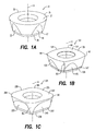
- FIGS. 1A-1C Different inserts 21, 121, 221 of a family of cutting inserts are shown in FIGS. 1A-1C .
- Each insert 21, 121, 221 has a different geometry, such as, but not necessarily, having cutting edges that are of different shapes when viewed in plan.
- the insert 21 has a circular shape when viewed in plan
- the insert 121 has a four-sided shape when viewed in plan with cutting edges having radii equal to a diameter of a circle inscribed in the corresponding circular insert 21 and with radiused corners between the cutting edges
- the insert 221 has a four-sided shape when viewed in plan with cutting edges having radii greater than the diameter of a circle inscribed in the insert and with a plurality of (three) chamfers between the cutting edges.
- the differences in geometry can involve other features of the insert, instead of or in addition to the cutting edges, such as the presence or absence of chipbreakers, flat or curved wiper surfaces, etc.
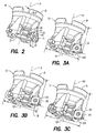
- Each insert 21, 121, 221 of the plurality of different inserts is adapted to be mounted in a common insert-receiving pocket 23 on a toolholder 25 as seen in FIG. 2 , thereby forming a milling cutting tool 27 as seen in FIGS. 3A-3C .
- At least one and, ordinarily, a plurality of common pockets 23 are provided on the toolholder 25 for receiving a corresponding plurality of inserts.
- the pockets 23 and the inserts 21, 121, 221 are configured such that an outer diameter D generated by a milling cutting tool 27 formed when inserts are mounted in the toolholder can be the same, regardless which of the inserts 21, 121, or 221 in the family are provided in the pockets.
- An axial length L of the milling cutting tool 27 measured from a forwardmost cutting edge 29, 129, 229 on each insert of the plurality of inserts 21, 121, 221, when mounted in the pocket 23, to a rearwardmost point 31 on the toolholder can be the same regardless which insert of the plurality of inserts is mounted in the pocket.
- each insert of the plurality of different inserts has at least one insert supporting surface 33, 133, 233 having a plane P, and a cutting edge 35, 135, 235 associated with and on a substantially opposite side of the insert from the at least one insert supporting surface.
- the inserts 21, 121, 221 have a central axis A extending between a top 37, 137, 237 ( FIGS. 1A-1C ) of the insert and a bottom 39, 139, 239 of the insert.
- the insert is indexable to a plurality of different positions about the central axis A to permit using different cutting edges on the insert.
- each cutting insert has a bottom supporting surface 39, 139, 239 and an axis of rotation A.
- a plurality of side insert supporting surfaces 33, 45, 133, 145, 233, 245 and a plurality of cutting edge portions 35, 29, 135, 129, 235, 229 corresponding to each of the plurality of side insert supporting surfaces are arranged around the axis of rotation A.
- the cutting edge portions for each insert 21, 121, 221 are generally convex and the cutting edge portions for different inserts have different curvatures.
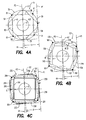
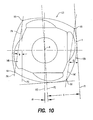
- a first plane P 1 parallel to the axis of rotation A and tangent to the cutting edge at a face contact point Y (or some other, arbitrary or non-arbitrary point) on the cutting edge is disposed at a predetermined distance X from a parallel second plane P2 extending through the axis of rotation and rotated at a predetermined angle ⁇ relative to a third plane P3 intersecting a corresponding side insert supporting surface along a line 41, 141, 241 ( FIGS. 4A-4C and 10 ) substantially perpendicular to the axis of rotation A.
- the line 41, 141, 241 may be, but need not be, a line defining a base of the side insert supporting surface.
- FIGS. 4A-4C show the angle ⁇ measured relative to a plane P3' parallel to plane P3 but offset relative to the plane P3 to extend through the axis of rotation like the plane P2.
- one cutting insert 21 of the family of cutting inserts is substantially circular when viewed along the axis of rotation A.
- the predetermined distance X for all of the inserts is therefore equal to the radius of the cutting insert 21. If a circular insert is not a member of the family of inserts, the distance X can be substantially any desired value.
- the predetermined angle ⁇ can be determined for a single insert of the family of inserts and applied to the rest of the members of the family.
- FIG. 10 shows how the angle ⁇ is determined for the insert 121 of the family of inserts 21, 121, 221.
- the angle ⁇ is substantially equal to a difference between an offset angle ⁇ of the cutting insert 121 and an angle of rotation M of the third plane P3 relative to a fourth plane P4 parallel to the axis of rotation and intersecting opposite end points 161 of the cutting edge (edge 129 shown for purposes of illustration) corresponding to the side insert supporting surface (surface 145 shown for purposes of illustration) intersected by the third plane, the angles being considered when the insert is viewed in "plan" along the axis of rotation A of the insert.
- the offset angle ⁇ is measured between the first plane P1 and a fourth plane P4' parallel to the axis of rotation A and extending between end points 161 of the cutting edge 129 (parallel to plane P4).
- the angle ⁇ is measured between the plane P1 (parallel to P2) and the plane P3.
- the angle ⁇ is described as being “substantially” equal to the difference between the offset angle ⁇ and the angle of rotation M because it may be desirable to further adjust the angle for purposes of fine tuning, such as if the insert is oriented at a non-zero axial angle, i.e., a plane of the bottom surface 49 of the pocket 23 is not parallel to the axis of rotation LA of the toolholder 25.
- it may be desirable to further adjust the angle ⁇ e.g., ⁇ about 1°.
- a second cutting insert 21 of the family of cutting inserts is substantially circular when viewed along the axis of rotation, and the predetermined distance X is equal to the radius R21 of the cutting insert.
- the plurality of cutting edges 29, 35 of the first cutting insert 121 have a radius R121 substantially equal to a diameter of the second cutting insert, i.e., 2 times R21.
- the cutting edges of non-circular inserts do not, however, have to be arcs of circles, i.e., they need not have a particular radius.
- the predetermined angle ⁇ will ordinarily be between 15° and -15° and, preferably, greater than 0°.
- the side insert supporting surfaces may be but need not be substantially planar. Where the side insert supporting surfaces are described as having a plane, it will be understood that this can refer to a reference plane associated with the surface and that the surface is not necessarily planar.
- the relationship can and ordinarily does apply to any insert supporting surface and the associated cutting edge on the opposite side of the insert from the insert supporting surface so that, regardless how any insert is indexed about the axis A, the milling cutting tool 27 will generate the same diameter D and have the same axial length L.
- the inserts 21, 121, 221 as shown in, for example, FIGS. 1A-1C are shown having integrated anvils 47, 147, 247 such as are disclosed in EP 0 458 003 B1 , which is incorporated by reference.
- the height of the integrated anvil 47, 147, 247 is ordinarily about 15% of the total insert 21, 121, 221 thickness.
- each of the inserts 21, 121, 221 can be configured so that a circle inscribed in the inserts and tangent to the lowest point on each insert supporting surface has the same diameter for each insert. This structure can facilitate fitting the different insert shapes into toolholder pockets of the same size.
- the pocket 23 ordinarily includes a flat bottom surface 49, and flat, generally axially extending and flat, generally radially extending side abutment surfaces 51 and 53.
- the bottom surface 39, 139, 239 of the insert, and the insert supporting surfaces 33, 133, 233 and 45, 145, 245 are ordinarily, but not necessarily, substantially flat and planar, at least at points where they are intended to abut corresponding abutment surfaces 49, 51, 53 in the pocket 23.
- the inserts illustrated in the present application are indexable to four different positions to utilize four different cutting edges provided on the insert and it will be appreciated that the identification of the insert supporting surfaces by particular reference numerals is for purposes of discussion only, and that the insert is typically rotationally symmetrical about the central axis A in four different positions oriented at 90° to each other.
- the insert can be indexable to some number of different positions other than four, such as two or eight different positions.
- the bottom surfaces of the insert and the pocket may be provided with structures such as mating grooved surfaces to facilitate, among other things, seating of the insert with reduced possibility of rotation.
- the bottom and insert supporting surfaces of the insert and/or the bottom and abutment surfaces of the pocket may be provided with structures such as recesses to facilitate, among other things, ensuring multi-point contact between the insert surfaces and the corresponding pocket surfaces.
- the radial and axial abutment surfaces in the pocket need not and ordinarily do not extend only in the radial and axial directions relative to the toolholder. As seen in FIG.
- the radial abutment surface 51 extends at an angle AR to the axis LA of the toolholder 25
- the axial abutment surface 53 extends at an angle AA to the axis of the toolholder
- the bottom abutment surface 49 extends at the angle K ( FIG. 2 ) to the axis of the toolholder.
- the radial and axial abutment surfaces 51 and 53 are substantially flat and planar, at least where they abut the insert supporting surfaces, and that the radial and axial abutment surfaces extend only radially and axially relative to the toolholder 25.
- the insert supporting surfaces 33, 133, 233 and 45, 145, and 245 are substantially flat and planar, at least where they abut the insert supporting surfaces, and that they are substantially perpendicular to each other.
- the flat surfaces of the abutment surfaces and the insert supporting surfaces act as seating faces and secure the insert against rotation relative to the toolholder during machining operations.
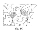
- the pocket 23 shown in FIG. 5A shows the general area of contact C' on the radial and axial abutment surfaces 51 and 53 of the insert-supporting surface portions 33 and 45 (not shown in FIG. 5A ) of the insert 21, the pocket 23 shown in FIG. 5B shows the general area of contact C" on the radial and axial abutment surfaces 51 and 53 of the insert supporting surface portions 133 and 145 (not shown in FIG. 5B ) of the insert 121, and the pocket 23 shown in FIG.
- FIG. 5C shows the general area of contact C'" on the radial and axial abutment surfaces 51 and 53 of the insert supporting surfaces portions 233 and 245 (not shown in FIG. 5C ).
- the area of contact is not necessarily the same for each insert in the family of inserts.
- the area of contact is also not necessarily the same for the abutment of any particular pair of insert supporting surfaces and their associated abutment surfaces, even though FIG. 5A shows each of the areas of contact C' being substantially the same, FIG. 5B shows each of the areas of contact C" being substantially the same, and FIG. 5C shows each of the areas of contact C"' being substantially the same.
- the insert supporting surfaces 33, 133, 233 and 45, 145, 245 of an insert 21, 121, 221 in the family of inserts will begin at the top of the integrated anvil 47, 147, 247 and finish at some point in the flank face 55, 155, 255 and 57, 157, 257 of the insert, ordinarily below the cutting edge 29, 129, 229 and 35, 135, 235.
- the flat insert supporting surfaces 33, 133, 233 and 45, 145, 245 will ordinarily define a larger angle with a line parallel to the central axis A than the flank face 55, 155, 255 and 57, 157, 257.
- the insert supporting surfaces 33, 133, 233 and 45, 145, 245 define an angle I of 22° with the line parallel to the central axis A and the flank faces 55, 155, 255 and 57, 157, 257 define an angle J of 15° with the line parallel to the central axis A.
- the inserts have four insert supporting surfaces and four associated cutting edges on opposite sides of the insert from the insert supporting surfaces.
- Adjacent insert supporting surfaces can be oriented at angles of 90° around the axis of rotation A of the insert.
- Other embodiments may, of course, have more or fewer insert supporting surfaces and cutting edges.
- the height of the insert supporting surfaces 33 and 45 of the insert 21 is about 75% of the total height of the insert.
- the insert 21 is typically not used to provide a high feed rate.
- Using a milling tool 27 provided with circular inserts 21 in a manner to reach maximum material removal rate ordinarily involves a high depth of cut ap , without a high feed rate, and high radial cutting forces. Short tool overhang is preferred in such operations to avoid chatter.
- the insert is four-sided and has insert supporting surfaces 145 and 133 disposed on opposite sides of the insert from cutting edges 129 and 135, respectively.
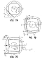
- the cutting edges 129 and 135 are arcs of a circle having a radius R121 ( FIG. 7B ) equal to a diameter of a circle inscribed in the insert 21.
- the diameter of a circle inscribed in the insert 121 may be smaller than the diameter of the circle inscribed in the insert 21 to facilitate providing inserts that, when mounted on the same toolholder, will generate the same diameters and lengths.
- There are four insert supporting surfaces and adjacent insert supporting surfaces can form angles of 90°. As seen in FIG.
- the insert supporting surfaces 145 and 133 can be "rotated” or “offset” so that the line 141 defines an angle M with a line 159 extending through end points of the cutting edges 129 and 135 at corners 161 of the insert 121.
- the angle M is preferably 9° and could be between 7° and 9° (or some other range, depending upon the configuration of the insert and the toolholder).
- offsetting the insert supporting surfaces facilitates increasing a ramping angle compared to a "centered" insert supporting surface, i.e., one where the angle M is 0°.
- the rotation or offset of the insert supporting surfaces 133 and 145 can expose more of a ramping cutting edge 171 (shown circled in FIG. 8 ), thereby facilitating entry into a workpiece with a milling cutting tool (not shown in FIG.
- the maximum depth of cut ap ( FIGS. 7B and 8 ) of the high feed insert 121 is lower than with the circular insert 21, but the feed per tooth can be increased.
- the leading angle Kr is decreased compared to an equivalent round shape insert.
- a milling tool 27 provided with high feed inserts 121 tends to reduce radial cutting forces, which can be a benefit when tool overhang is long.
- the insert is four-sided and has insert supporting surfaces 245 and 233 disposed on opposite sides of the insert from cutting edges 229 and 235, respectively.
- the radius R221 can be "offset" as seen in FIG. 7C in the sense that each cutting edge can be considered to lie along an arc of a respective circle, and a first line 1L (coinciding with radius R) extending through a centerpoint CP of each cutting edge 229, 235 and a radial center RC of its respective circle forms a non-zero angle G with a second line 2L extending through the centerpoint of each cutting edge and an axial center (of rotation) A of the insert.
- the line 1L coincident with the radii R21 and R121 of the inserts and extending through the centerpoint CP of the cutting edges in the inserts 21 and 121 shown in FIGS. 7A and 7B forms a 0° angle with the line 2L extending through the centerpoint of the cutting edges and the central axis A of the inserts.
- insert supporting surfaces and adjacent insert supporting surfaces can form angles of 90°.
- the insert supporting surfaces 245 and 233 can be “rotated” or “offset” so that the line 241 defines an angle N with a line 259 extending through end points of the cutting edges 229 and 235 at corners 261 of the insert 221.
- the insert supporting surfaces can be considered to be “rotated” or “offset” in the sense that each insert supporting surface forms a non-zero angle N with a third line 3L perpendicular to the second line 2L.
- the angle N is preferably 3.5° and may be between 0.5° and 5° (or some other range, depending upon insert and toolholder configuration), which facilitates decreasing the leading angle for small depth of cut with a large radius cutting edge which tends to be more useful in a finishing operation.
- the "rotation" of the angle N in the insert 221 and the angle M in the insert 121 can be in the opposite direction relative to the lines 259 and 159, respectively, to achieve desired results, particularly where the radial and axial abutment surfaces 51 and 53 in the pocket 23 form an angle with the axis LA of the toolholder 25 and with a perpendicular to the axis of the toolholder.
- each cutting edge defines an arc of circle and each insert supporting surface of the second one of the plurality of inserts has a plane P.
- a radial line 2L bisecting an arc of a circle of the cutting edge can be perpendicular to an insert supporting surface on the same side of the insert, as is the case with the insert 21 shown in FIG. 4A , or non-perpendicular to an insert supporting surface on a same side of the insert, as is the case with the inserts 121 and 221 shown in FIGS. 4B and 4C .
- a further recess 69 can be provided behind the radial abutment surface 51.
- the recesses 63, 65, 67, and 69 can facilitate seating of the inserts in the pocket 23 without interference between corners of the inserts and corners of the pocket.
- the axial angle K of the insert pocket 23 - the angle that the bottom surface 49 of the pocket forms with the longitudinal axis LA of the toolholder 25 -- can be set at an angle different from zero.
- the angle K will ordinarily be selected depending upon the angle of the insert flank faces 55, 155, 255 and 57, 157, 257.
- the axial angle K of the insert pocket may be set at, for example, 9°, which can facilitate machining of various materials, particularly "sticky" materials such as titanium, stainless steel, and high temperature alloys.
- the "comers" 61 between adjacent cutting edges are ordinarily continuations of the circular edge surface.
- the corners 161 between curved cutting edges are typically radiused.
- the corners 261 between curved cutting edges are typically chamfered to form three generally flat chamfer surfaces 273a, 273b, 273c ( FIG. 7C ) that form different angles with the line 259 through ends of the cutting edges.
- the surface 273a forms a 30° angle
- the surface 273b forms a 45° angle
- the surface 273c forms a 60° angle.
- These chamfers surfaces 273a, 273b, 273c coupled with offset insert supporting surfaces and an offset circular arc of the cutting edge, help to increase depth of cut with a low setting angle.
- the setting angle may be 30° instead of immediately transitioning to, say, a 45° setting angle.
- flank surfaces 55 and 57 between the cutting edges 29 and 35 are portions of a truncated cone.
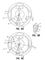
- flat wiper surfaces 75' can be provided beneath or behind straight wiper edges 77' along an otherwise circular cutting edge 29' having radius R or, as seen with respect to the embodiment 21" shown in FIG. 9C , curved wiper surfaces 75" can be provided beneath or behind curved wiper edges 77", the wiper edges RWE having a radius different (generally larger) than the radius R of the rest of the cutting edge 29" and having a radius different from a radius of the flank 55" at the same height along the axis A of the insert.
- flanks beneath the cutting edges of the inserts 121 and 221 are ordinarily curved portions of truncated cones but, if desired, may have wiper surfaces that are flat or that have radii different from the radii of the flanks. Using inserts with wiper surfaces can produce high quality surface finishes.
- the inserts 21' and 21" have one or more insert supporting surfaces 33' and 33" corresponding to a respective wiper surface 75' and 75" and a respective wiper edge 77' and 77".
- the side surface comprises at least one wiper surface 75', 75" provided behind the wiper edge in the flank wear direction of the insert.
- Each insert supporting surface 33' and 33" extends through a first angle ⁇ 1 (not necessarily the same for each insert) measured through the axis of rotation A of the insert, and the respective wiper edge 77' and 77" and respective wiper surface 75' and 75” extends through a second, angle ⁇ 2 measured through the axis of rotation A of the insert.
- a centerline ⁇ 1 bisecting the first angle ⁇ 1 forms a non-zero angle ⁇ (not necessarily the same for each insert) with a centerline ⁇ 2 bisecting the second angle ⁇ 2.
- the insert 21' (and 21") has a top 37' and a bottom 39', Fig. 9B .
- the angle formed between the top surface and the insert supporting surface 33' is preferably acute and smaller than an acute angle formed between the top surface and the wiper surface 75'.
- Each respective wiper surface 75' and 75" may intersect an insert supporting surface 33' and 33".
Description
- The present invention relates generally to cutting inserts and, more particularly, to families of cutting inserts usable in the same toolholders.
- In milling cutting operations, use of an insert of circular shape permits providing a depth of cut equal to one half of insert diameter, or generating a radius at the bottom of a workpiece. The leading angle of a milling cutting tool with a circular insert depends on depth of cut. The higher the depth of cut is, the higher the leading angle is. To reach the maximum material removal rate using circular inserts, the conventional strategy is to machine with high depth and avoid reaching a high feed per tooth. This strategy tends to create high radial cutting forces which are acceptable when the tool overhang is short but which create chatter effects when total tool length becomes large.
JP 11 090723 - With a high feed insert, such as an insert having four cutting edges, the maximum depth of cut is reduced due to the insert shape and, consequently, the leading angle is reduced. To reach the maximum material removal rate using a high feed insert, the strategy differs from that used with circular inserts. Because the leading angle and depth of cut is typically reduced in a multi-edge insert relative to a circular insert, the feed per tooth can be increased. This strategy tends to reduce radial cutting forces (at least relative to high depth of cut and/or high leading angle operations), which can be a benefit when long overhang is necessary.
- When using a finishing insert, the depth of cut and the leading angle are generally reduced further, and feed rate can be increased further.
- When switching from use of one type of insert to another, it is ordinarily necessary to adjust various settings on the CNC machine to account for different lengths and diameters of the cutting tool. It is desirable to provide a milling toolholder on which several different kinds of inserts could be mounted for operations such as copy milling, face milling, plunging, helical interpolation, and the like. It is also desirable to provide inserts that can be mounted on the same toolholder so that, regardless which insert is mounted on the toolholder, the tool will generate the same diameter and have the same length.
- According to the present invention, a cutting insert is provided, the cutting insert having a top surface, a side surface, and a bottom surface, an intersection between the top surface and the side surface defining a substantially circular cutting edge, the cutting edge comprising at least one wiper edge and the side surface comprising at least one wiper surface provided behind the wiper edge. The wiper edge and the wiper surface are radiused and the wiper edge has a larger radius than a radius of the cutting edge.
- The features and advantages of the present invention are well understood by reading the following detailed description in conjunction with the drawings in which like numerals indicate similar elements and in which:
-
FIGS. 1A, 1B, and 1C are perspective views of inserts not according to aspects of the present invention; -
FIG. 2 is a perspective view of a toolholder not according to an aspect of the present invention; -
FIGS. 3A, 3B, and 3C are perspective views of milling cutting tools not according to aspects of the present invention; -
FIGS. 4A, 4B, and 4C are bottom plan views of inserts not according to aspects of the present invention; -
FIGS. 5A, 5B , and5C are perspective views of pockets in toolholders not according to aspects of the present invention; -
FIGS. 6A, 6B, and 6C are side views of inserts not according to aspects of the present invention; -
FIGS. 7A, 7B, and 7C are bottom plan views of inserts not according to aspects of the present invention; -
FIG. 8 is a schematic view of parts of a milling cutting tool according to an aspect of the present invention illustrating a ramping angle of the milling cutting tool; -
FIGS. 9A and 9C are bottom plan views of inserts according to aspects of the present invention, whileFig. 9B shows a cross-section according to the line IXB-IXB inFig. 9A ; and -
FIG. 10 is a bottom plan view of an insert according to an aspect of the present invention: -
Different inserts FIGS. 1A-1C . Eachinsert insert 21 has a circular shape when viewed in plan, theinsert 121 has a four-sided shape when viewed in plan with cutting edges having radii equal to a diameter of a circle inscribed in the correspondingcircular insert 21 and with radiused corners between the cutting edges, and theinsert 221 has a four-sided shape when viewed in plan with cutting edges having radii greater than the diameter of a circle inscribed in the insert and with a plurality of (three) chamfers between the cutting edges. The differences in geometry can involve other features of the insert, instead of or in addition to the cutting edges, such as the presence or absence of chipbreakers, flat or curved wiper surfaces, etc. - Each
insert pocket 23 on atoolholder 25 as seen inFIG. 2 , thereby forming amilling cutting tool 27 as seen inFIGS. 3A-3C . At least one and, ordinarily, a plurality ofcommon pockets 23 are provided on thetoolholder 25 for receiving a corresponding plurality of inserts. Ordinarily, as seen inFIGS. 3A-3C , at any given time, only one type of insert of the family of inserts is mounted on the toolholder, i.e., a plurality ofinserts 21, a plurality ofinserts 121, or a plurality ofinserts 221, however, it is also possible to mount different types of the inserts of the family of inserts on a single toolholder, e.g., aninsert 21 with aninsert 121 and/or 221. - According the invention, the
pockets 23 and theinserts milling cutting tool 27 formed when inserts are mounted in the toolholder can be the same, regardless which of theinserts milling cutting tool 27 measured from aforwardmost cutting edge inserts pocket 23, to arearwardmost point 31 on the toolholder can be the same regardless which insert of the plurality of inserts is mounted in the pocket. - According the invention, to provide a
milling cutting tool 27 that generates the same diameter D regardless which of theinserts toolholder 25, as seen for example inFIGS. 4A-4C , each insert of the plurality of different inserts has at least oneinsert supporting surface cutting edge inserts top FIGS. 1A-1C ) of the insert and abottom - As seen in
FIGS. 4A-4C , for a family of cuttinginserts bottom supporting surface insert supporting surfaces cutting edge portions insert line 41, 141, 241 (FIGS. 4A-4C and10 ) substantially perpendicular to the axis of rotation A. Theline FIGS. 4A-4C show the angle α measured relative to a plane P3' parallel to plane P3 but offset relative to the plane P3 to extend through the axis of rotation like the plane P2. - In the family of inserts shown in
FIGS. 4A-4C , one cuttinginsert 21 of the family of cutting inserts is substantially circular when viewed along the axis of rotation A. The predetermined distance X for all of the inserts is therefore equal to the radius of the cuttinginsert 21. If a circular insert is not a member of the family of inserts, the distance X can be substantially any desired value. - The predetermined angle α can be determined for a single insert of the family of inserts and applied to the rest of the members of the family.
FIG. 10 shows how the angle α is determined for theinsert 121 of the family ofinserts insert 121 and an angle of rotation M of the third plane P3 relative to a fourth plane P4 parallel to the axis of rotation and intersectingopposite end points 161 of the cutting edge (edge 129 shown for purposes of illustration) corresponding to the side insert supporting surface (surface 145 shown for purposes of illustration) intersected by the third plane, the angles being considered when the insert is viewed in "plan" along the axis of rotation A of the insert. The offset angle θ is measured between the first plane P1 and a fourth plane P4' parallel to the axis of rotation A and extending betweenend points 161 of the cutting edge 129 (parallel to plane P4). In other words, the angle α is measured between the plane P1 (parallel to P2) and the plane P3. The angle α is described as being "substantially" equal to the difference between the offset angle θ and the angle of rotation M because it may be desirable to further adjust the angle for purposes of fine tuning, such as if the insert is oriented at a non-zero axial angle, i.e., a plane of thebottom surface 49 of thepocket 23 is not parallel to the axis of rotation LA of thetoolholder 25. For example, depending upon the axial angle of the insert in thetoolholder 25, it may be desirable to further adjust the angle α, e.g., ± about 1°. - In the invention, a
second cutting insert 21 of the family of cutting inserts is substantially circular when viewed along the axis of rotation, and the predetermined distance X is equal to the radius R21 of the cutting insert. The plurality of cuttingedges first cutting insert 121 have a radius R121 substantially equal to a diameter of the second cutting insert, i.e., 2 times R21. The cutting edges of non-circular inserts do not, however, have to be arcs of circles, i.e., they need not have a particular radius. - The predetermined angle α will ordinarily be between 15° and -15° and, preferably, greater than 0°. The side insert supporting surfaces may be but need not be substantially planar. Where the side insert supporting surfaces are described as having a plane, it will be understood that this can refer to a reference plane associated with the surface and that the surface is not necessarily planar.
- To provide a
milling cutting tool 27 as shown inFIGS. 3A-3C that has the same axial length L measured from aforwardmost cutting edge inserts pocket 23, to arearwardmost point 31 on thetoolholder 25, the relationship between the cuttingedge insert supporting surface edge insert supporting surface milling cutting tool 27 will generate the same diameter D and have the same axial length L. - The
inserts FIGS. 1A-1C are shown having integratedanvils EP 0 458 003 B1 , which is incorporated by reference. The height of theintegrated anvil total insert inserts - As seen in
FIG. 5A-5C , thepocket 23 ordinarily includes aflat bottom surface 49, and flat, generally axially extending and flat, generally radially extending side abutment surfaces 51 and 53. Thebottom surface insert supporting surfaces pocket 23. When aninsert pocket 23 having twoabutment surfaces insert supporting surfaces - In other embodiments (not shown), the bottom surfaces of the insert and the pocket may be provided with structures such as mating grooved surfaces to facilitate, among other things, seating of the insert with reduced possibility of rotation. In other embodiments, the bottom and insert supporting surfaces of the insert and/or the bottom and abutment surfaces of the pocket may be provided with structures such as recesses to facilitate, among other things, ensuring multi-point contact between the insert surfaces and the corresponding pocket surfaces. The radial and axial abutment surfaces in the pocket need not and ordinarily do not extend only in the radial and axial directions relative to the toolholder. As seen in
FIG. 8 , for example, the radial abutment surface 51 (shown in phantom) extends at an angle AR to the axis LA of thetoolholder 25, the axial abutment surface 53 (shown in phantom) extends at an angle AA to the axis of the toolholder, and the bottom abutment surface 49 (shown in phantom) extends at the angle K (FIG. 2 ) to the axis of the toolholder. - For purposes of discussion, it will be understood that the radial and axial abutment surfaces 51 and 53 are substantially flat and planar, at least where they abut the insert supporting surfaces, and that the radial and axial abutment surfaces extend only radially and axially relative to the
toolholder 25. Likewise, merely for purposes of discussion, it will further be understood that theinsert supporting surfaces - The flat surfaces of the abutment surfaces and the insert supporting surfaces act as seating faces and secure the insert against rotation relative to the toolholder during machining operations. The
pocket 23 shown inFIG. 5A shows the general area of contact C' on the radial and axial abutment surfaces 51 and 53 of the insert-supportingsurface portions 33 and 45 (not shown inFIG. 5A ) of theinsert 21, thepocket 23 shown inFIG. 5B shows the general area of contact C" on the radial and axial abutment surfaces 51 and 53 of the insert supportingsurface portions 133 and 145 (not shown inFIG. 5B ) of theinsert 121, and thepocket 23 shown inFIG. 5C shows the general area of contact C'" on the radial and axial abutment surfaces 51 and 53 of the insert supportingsurfaces portions 233 and 245 (not shown inFIG. 5C ). The area of contact is not necessarily the same for each insert in the family of inserts. The area of contact is also not necessarily the same for the abutment of any particular pair of insert supporting surfaces and their associated abutment surfaces, even thoughFIG. 5A shows each of the areas of contact C' being substantially the same,FIG. 5B shows each of the areas of contact C" being substantially the same, andFIG. 5C shows each of the areas of contact C"' being substantially the same. Ordinarily, as seen inFIGS. 4A-4C and6A-6C , theinsert supporting surfaces insert integrated anvil flank face cutting edge - As seen in
FIGS. 6A, 6B, and 6C , the flatinsert supporting surfaces flank face insert supporting surfaces - In inserts 21, 121, 221 shown in
FIGS 1A-1C ,3A-3C , and4A-4C , the inserts have four insert supporting surfaces and four associated cutting edges on opposite sides of the insert from the insert supporting surfaces. Adjacent insert supporting surfaces can be oriented at angles of 90° around the axis of rotation A of the insert. Other embodiments may, of course, have more or fewer insert supporting surfaces and cutting edges. - The height of the
insert supporting surfaces insert 21 is about 75% of the total height of the insert. An insert such as theinsert 21 is particularly useful in providing a high maximum depth of cut ap, usually with ap=Insert Diameter/2 = R21 as seen inFIG. 7A , and it typically has a relatively large setting or leading angle Kr. When theinsert 21 is used in an application where it provides a high depth of cut ap, it is typically not used to provide a high feed rate. Using amilling tool 27 provided withcircular inserts 21 in a manner to reach maximum material removal rate ordinarily involves a high depth of cut ap, without a high feed rate, and high radial cutting forces. Short tool overhang is preferred in such operations to avoid chatter. - In the
high feed insert 121 shown inFIGS. 1B ,3B , and4B , the insert is four-sided and hasinsert supporting surfaces edges FIG. 7B ) equal to a diameter of a circle inscribed in theinsert 21. The diameter of a circle inscribed in theinsert 121 may be smaller than the diameter of the circle inscribed in theinsert 21 to facilitate providing inserts that, when mounted on the same toolholder, will generate the same diameters and lengths. There are four insert supporting surfaces and adjacent insert supporting surfaces can form angles of 90°. As seen inFIG. 4B , theinsert supporting surfaces line 141 defines an angle M with aline 159 extending through end points of the cutting edges 129 and 135 atcorners 161 of theinsert 121. - In
high feed insert 121, the angle M is preferably 9° and could be between 7° and 9° (or some other range, depending upon the configuration of the insert and the toolholder). As seen inFIG. 8 , offsetting the insert supporting surfaces facilitates increasing a ramping angle compared to a "centered" insert supporting surface, i.e., one where the angle M is 0°. In particular, the rotation or offset of theinsert supporting surfaces 133 and 145 (shown in phantom) can expose more of a ramping cutting edge 171 (shown circled inFIG. 8 ), thereby facilitating entry into a workpiece with a milling cutting tool (not shown inFIG. 8 ) that does not have cutting inserts in a center of the tool by means of a larger ramping angle RA between the end of the ramping cutting edge and the tip of the cutting edge of the insert (shown in phantom) when rotated 180° about the longitudinal axis LA of the cutting tool. - The maximum depth of cut ap (
FIGS. 7B and8 ) of thehigh feed insert 121 is lower than with thecircular insert 21, but the feed per tooth can be increased. By offsetting theinsert supporting surfaces milling tool 27 provided with high feed inserts 121 tends to reduce radial cutting forces, which can be a benefit when tool overhang is long. - In the high
feed finishing insert 221 shown inFIGS. 1C ,3C , and4C the insert is four-sided and hasinsert supporting surfaces edges FIG. 7C ) greater than a diameter of a circle inscribed in theinsert 221, e.g., radius = 50 mm, or more, e.g., 100 mm, 200 mm, etc. - The radius R221 can be "offset" as seen in
FIG. 7C in the sense that each cutting edge can be considered to lie along an arc of a respective circle, and afirst line 1L (coinciding with radius R) extending through a centerpoint CP of eachcutting edge second line 2L extending through the centerpoint of each cutting edge and an axial center (of rotation) A of the insert. By way of contrast, theline 1L coincident with the radii R21 and R121 of the inserts and extending through the centerpoint CP of the cutting edges in theinserts FIGS. 7A and 7B forms a 0° angle with theline 2L extending through the centerpoint of the cutting edges and the central axis A of the inserts. - There are four insert supporting surfaces and adjacent insert supporting surfaces can form angles of 90°. As seen in
FIG. 4C , theinsert supporting surfaces line 241 defines an angle N with aline 259 extending through end points of the cutting edges 229 and 235 atcorners 261 of theinsert 221. As described differently with reference toFIG. 7C , the insert supporting surfaces can be considered to be "rotated" or "offset" in the sense that each insert supporting surface forms a non-zero angle N with athird line 3L perpendicular to thesecond line 2L. In an embodiment, the angle N is preferably 3.5° and may be between 0.5° and 5° (or some other range, depending upon insert and toolholder configuration), which facilitates decreasing the leading angle for small depth of cut with a large radius cutting edge which tends to be more useful in a finishing operation. The "rotation" of the angle N in theinsert 221 and the angle M in theinsert 121 can be in the opposite direction relative to thelines pocket 23 form an angle with the axis LA of thetoolholder 25 and with a perpendicular to the axis of the toolholder. - Regardless how many cutting edges are provided on an insert, in at least some inserts according the present invention, each cutting edge defines an arc of circle and each insert supporting surface of the second one of the plurality of inserts has a plane P. A
radial line 2L bisecting an arc of a circle of the cutting edge can be perpendicular to an insert supporting surface on the same side of the insert, as is the case with theinsert 21 shown inFIG. 4A , or non-perpendicular to an insert supporting surface on a same side of the insert, as is the case with theinserts FIGS. 4B and 4C . - The
pocket 23, in addition to having abottom surface 49, and radial and axial abutment surfaces 51 and 53, will ordinarily have arecess 63 at the intersection of the radial surface and the bottom surface, arecess 65 at the intersection of the axial abutment surface and the bottom surface, and arecess 67 at the intersection of the axial abutment surface and the radial abutment surface. Afurther recess 69 can be provided behind theradial abutment surface 51. Therecesses pocket 23 without interference between corners of the inserts and corners of the pocket. - As seen in
FIG. 2 , the axial angle K of the insert pocket 23 - the angle that thebottom surface 49 of the pocket forms with the longitudinal axis LA of thetoolholder 25 -- can be set at an angle different from zero. The angle K will ordinarily be selected depending upon the angle of the insert flank faces 55, 155, 255 and 57, 157, 257. Where the insert flank faces 55, 155, 255 and 57, 157, 257 form an angle J of 15°, for example, the axial angle K of the insert pocket may be set at, for example, 9°, which can facilitate machining of various materials, particularly "sticky" materials such as titanium, stainless steel, and high temperature alloys. - In the
circular insert 21, the "comers" 61 between adjacent cutting edges are ordinarily continuations of the circular edge surface. In thehigh feed insert 121, thecorners 161 between curved cutting edges are typically radiused. - In the finishing
insert 221, thecorners 261 between curved cutting edges are typically chamfered to form three generallyflat chamfer surfaces 273a, 273b, 273c (FIG. 7C ) that form different angles with theline 259 through ends of the cutting edges. In the surface 273a forms a 30° angle, the surface 273b forms a 45° angle, and thesurface 273c forms a 60° angle. These chamfers surfaces 273a, 273b, 273c, coupled with offset insert supporting surfaces and an offset circular arc of the cutting edge, help to increase depth of cut with a low setting angle. For example, if the depth of cut is relatively small, the setting angle may be 30° instead of immediately transitioning to, say, a 45° setting angle. - In the
insert 21, the flank surfaces 55 and 57 between the cutting edges 29 and 35 are portions of a truncated cone. However, as seen in the embodiment 21' shown inFIGS. 9A and 9B , flat wiper surfaces 75' can be provided beneath or behind straight wiper edges 77' along an otherwise circular cutting edge 29' having radius R or, as seen with respect to theembodiment 21" shown inFIG. 9C , curved wiper surfaces 75" can be provided beneath or behind curved wiper edges 77", the wiper edges RWE having a radius different (generally larger) than the radius R of the rest of thecutting edge 29" and having a radius different from a radius of theflank 55" at the same height along the axis A of the insert. The flanks beneath the cutting edges of theinserts - The
inserts 21' and 21" have one or moreinsert supporting surfaces 33' and 33" corresponding to arespective wiper surface respective wiper edge 77' and 77". Thus the side surface comprises at least onewiper surface insert supporting surface 33' and 33" extends through a first angle β1 (not necessarily the same for each insert) measured through the axis of rotation A of the insert, and therespective wiper edge 77' and 77" andrespective wiper surface Fig. 9B . The angle formed between the top surface and the insert supporting surface 33' is preferably acute and smaller than an acute angle formed between the top surface and thewiper surface 75'. Eachrespective wiper surface insert supporting surface 33' and 33". - In the present application, the use of terms such as "including" is open-ended and is intended to have the same meaning as terms such as "comprising" and not preclude the presence of other structure, material, or acts. Similarly, though the use of terms such as "can" or "may" is intended to be open-ended and to reflect that structure, material, or acts are not necessary, the failure to use such terms is not intended to reflect that structure, material, or acts are essential. To the extent that structure, material, or acts are presently considered to be essential, they are identified as such.
- While this invention has been illustrated and described in accordance with a preferred embodiment, it is recognized that variations and changes may be made therein without departing from the invention as set forth in the claims.
Claims (8)
- A cutting insert (21', 21"), the cutting insert having a top surface, a side surface, and a bottom surface, an intersection between the top surface and the side surface defining a substantially circular cutting edge (29', 29"), wherein the cutting edge comprises at least one wiper edge (77', 77") and the side surface comprises at least one wiper surface (75', 75") provided behind the wiper edge, characterized in that the wiper edge (77") and the wiper surface (75") are radiused and that the wiper edge (77") has a larger radius (RWE) than a radius (R) of the cutting edge (29").
- The cutting insert (21', 21") as set forth in claim 1, wherein the side surface comprises a truncated conical portion.
- The cutting insert (21', 21") as set forth in any of claims 1-2, wherein the side surface comprises at least one insert supporting surface portion (33', 33").
- The cutting insert (21', 21") as set forth in claim 3, wherein the insert supporting surface portion (33', 33") is substantially flat.
- The cutting insert (21', 21") as set forth in any of claims 3-4, characterized in that there are a plurality of insert supporting surface portions (33', 33") provided in the side surface, each insert supporting surface portion corresponding to a respective wiper edge (77', 77") and a respective wiper surface (75', 75").
- The cutting insert (21', 21") as set forth in claim 5, characterized in that each insert supporting surface (33', 33") extends through a first angle (β1) measured through the axis of rotation (A) of the insert, and the respective wiper edge (77', 77") and respective wiper surface (75', 75") extends through a second angle (β2) measured through the axis of rotation (A) of the insert.
- The cutting insert (21', 21") as set forth in claim 6, characterized in that a centerline (γ1) bisecting the first angle (β1) forms a non-zero angle (δ) with a centerline (γ2) bisecting the second angle (β2).
- The cutting insert (21') as set forth in any of claims 1-7, characterized in that the wiper edge (77') is substantially straight and the wiper surface (75') is substantially flat.
Applications Claiming Priority (3)
| Application Number | Priority Date | Filing Date | Title |
|---|---|---|---|
| SE0801513A SE532555C2 (en) | 2008-06-26 | 2008-06-26 | Cut with flat phase eggs and associated flat surface |
| SE0801512A SE532554C2 (en) | 2008-06-26 | 2008-06-26 | Family with inserts, milling tools and inserts |
| PCT/SE2009/050652 WO2009157851A1 (en) | 2008-06-26 | 2009-06-03 | A cutting insert with a wiper edge |
Publications (3)
| Publication Number | Publication Date |
|---|---|
| EP2326447A1 EP2326447A1 (en) | 2011-06-01 |
| EP2326447A4 EP2326447A4 (en) | 2013-04-24 |
| EP2326447B1 true EP2326447B1 (en) | 2014-04-16 |
Family
ID=41444767
Family Applications (2)
| Application Number | Title | Priority Date | Filing Date |
|---|---|---|---|
| EP09770475.3A Withdrawn EP2326446A4 (en) | 2008-06-26 | 2009-06-03 | Family of cutting inserts, milling cutting tool, and cutting insert background and summary |
| EP09770476.1A Active EP2326447B1 (en) | 2008-06-26 | 2009-06-03 | A cutting insert with a wiper edge |
Family Applications Before (1)
| Application Number | Title | Priority Date | Filing Date |
|---|---|---|---|
| EP09770475.3A Withdrawn EP2326446A4 (en) | 2008-06-26 | 2009-06-03 | Family of cutting inserts, milling cutting tool, and cutting insert background and summary |
Country Status (5)
| Country | Link |
|---|---|
| US (2) | US9149878B2 (en) |
| EP (2) | EP2326446A4 (en) |
| KR (2) | KR101549717B1 (en) |
| CN (2) | CN102046314B (en) |
| WO (2) | WO2009157851A1 (en) |
Families Citing this family (17)
| Publication number | Priority date | Publication date | Assignee | Title |
|---|---|---|---|---|
| KR101103216B1 (en) * | 2009-05-19 | 2012-01-05 | 대구텍 유한회사 | Double-sided cutting insert having a circular shape and cutting tool using the same |
| DE102010000640A1 (en) * | 2010-03-04 | 2011-09-08 | Gühring Ohg | end mill |
| PL2409801T3 (en) * | 2010-07-21 | 2017-08-31 | Karl-Heinz Arnold Gmbh | Machining tool |
| EP2455172B1 (en) * | 2010-11-19 | 2013-01-16 | SECO TOOLS AB (publ) | Cutting insert with evolutive wedge or clearance angle and toolholder using such a cutting insert |
| KR101700703B1 (en) * | 2011-06-30 | 2017-01-31 | 쿄세라 코포레이션 | Cutting insert, cutting tool, and method for manufacturing cut workpiece using same |
| IN2014DN00173A (en) * | 2011-07-12 | 2015-06-05 | Hitachi Tool Eng | |
| AT12672U1 (en) * | 2011-09-15 | 2012-09-15 | Ceratizit Luxembourg S Ar L | SET OF CUTTING INSERTS AND MILLING TOOL HOLDER |
| DE102012103246A1 (en) * | 2012-04-13 | 2013-10-17 | Gühring Ohg | Cutting insert and cutting tool |
| KR101275033B1 (en) * | 2012-09-10 | 2013-06-17 | (주)코리아툴링 | Cutting insert compatible toolholder |
| JP6217355B2 (en) * | 2013-11-29 | 2017-10-25 | 三菱マテリアル株式会社 | Cutting edge replaceable cutting tool set and mounting method of cutting insert |
| KR101524540B1 (en) * | 2013-12-30 | 2015-06-01 | 한국야금 주식회사 | Insert and tool holder for mounting the same |
| TWM487821U (en) * | 2014-01-22 | 2014-10-11 | Shinmax Industry Co Ltd | Four-blade knife and knife shaft apparatus for planer |
| EP3000549B1 (en) * | 2014-09-24 | 2022-11-09 | Sandvik Intellectual Property AB | A cutting tool and a cutting insert for a chip-removing tool |
| JP6315223B2 (en) * | 2015-05-19 | 2018-04-25 | 株式会社タンガロイ | Tool body and cutting tool |
| CN106925801B (en) * | 2015-12-31 | 2019-07-05 | 王正铉 | A kind of novel lathe cutting tool using sliding extrusion technique finishing workpiece |
| EP3563956B1 (en) * | 2016-12-27 | 2023-05-24 | MOLDINO Tool Engineering, Ltd. | Cutting insert and indexable edge rotary cutting tool |
| USD1006075S1 (en) * | 2021-12-08 | 2023-11-28 | Green Manufacturing, Inc. | Tree stump grinding tooth |
Family Cites Families (42)
| Publication number | Priority date | Publication date | Assignee | Title |
|---|---|---|---|---|
| US4273479A (en) * | 1979-11-28 | 1981-06-16 | The Valeron Corporation | Cutter assembly for broaching |
| DE3724006A1 (en) * | 1987-07-21 | 1989-02-02 | Feldmuehle Ag | COMBINATION MILLER |
| SE463658B (en) | 1987-10-19 | 1991-01-07 | Seco Tools Ab | SHOULD BE REPLACED |
| JP2603151B2 (en) * | 1990-08-08 | 1997-04-23 | 東芝タンガロイ株式会社 | Face milling |
| US5145294A (en) | 1991-03-15 | 1992-09-08 | National Carbide Outlet, Inc. | Milling cutter capable of using indexable inserts of various shapes |
| US5346336A (en) * | 1992-11-04 | 1994-09-13 | Sandvik, Inc. | Metal-cutting insert having a round cutting edge |
| SE506679C2 (en) * | 1995-06-21 | 1998-01-26 | Seco Tools Ab | Cutting tools, preferably for milling |
| DE59702661D1 (en) | 1996-01-31 | 2000-12-28 | Widia Gmbh | CUTTING INSERT FOR ROUGHING AND FINISHING |
| JP3532031B2 (en) | 1996-04-26 | 2004-05-31 | 京セラ株式会社 | Drill inserts and indexable drills |
| SE511550C2 (en) | 1996-10-17 | 1999-10-18 | Seco Tools Ab | Tools and cutters for milling |
| IL119841A (en) * | 1996-12-16 | 2000-02-29 | Iscar Ltd | Cutting inserts |
| JPH10263916A (en) * | 1997-03-28 | 1998-10-06 | Mitsubishi Materials Corp | Throw-away tip |
| SE512736C2 (en) * | 1997-06-10 | 2000-05-08 | Seco Tools Ab | Face Milling Tools |
| JP4043080B2 (en) * | 1997-09-12 | 2008-02-06 | 株式会社タンガロイ | Throw-away tip for face milling |
| SE518839C2 (en) * | 1998-02-12 | 2002-11-26 | Seco Tools Ab | Cutting tools and cutting tools |
| SE518855C2 (en) | 1998-03-10 | 2002-11-26 | Seco Tools Ab | Cutting tools and cutting tools |
| IL123685A (en) | 1998-03-16 | 2001-09-13 | Iscar Ltd | Modular cutting tool assembly |
| JP2933079B1 (en) * | 1998-03-30 | 1999-08-09 | 住友電気工業株式会社 | Throwaway tips and face milling |
| JP4540764B2 (en) * | 1999-04-27 | 2010-09-08 | 株式会社タンガロイ | Cutting tools |
| IL132261A (en) | 1999-10-07 | 2003-09-17 | Iscar Ltd | Cutting tool assembly and cutting insert therefor |
| US6508612B1 (en) * | 2000-09-05 | 2003-01-21 | Kennametal Inc. | Milling cutter capable of using inserts of various geometrical shapes |
| JP2002178209A (en) * | 2000-12-15 | 2002-06-25 | Matsushita Electric Ind Co Ltd | Cutting tool for milling |
| SE520997C2 (en) | 2001-01-09 | 2003-09-23 | Sandvik Ab | Reversible cutter with grooved coupling surface against the holder and central material portion for fasteners |
| SE0100505L (en) | 2001-02-16 | 2002-07-23 | Btg Eclepens Sa | Self-adjusting blades |
| JP3483859B2 (en) * | 2001-03-06 | 2004-01-06 | オーエスジー株式会社 | Indexable insert and milling tool to which indexable insert is attached |
| KR100916280B1 (en) * | 2001-05-25 | 2009-09-10 | 히타치 쓰루 가부시키가이샤 | Insert-exchangeable rotary tool |
| US6604893B2 (en) * | 2001-07-27 | 2003-08-12 | Kennametal Inc. | Cutting insert with wiper |
| DE10162132B4 (en) | 2001-12-18 | 2006-02-23 | Kennametal Inc. | cutting board |
| JP3775321B2 (en) * | 2002-03-20 | 2006-05-17 | 三菱マテリアル株式会社 | Throw-away inserts and throw-away cutting tools |
| SE525714C2 (en) * | 2002-05-29 | 2005-04-12 | Sandvik Ab | Drilling tool and indexable drill bit where the center cutter's first delegate is removed from the center shaft |
| DE10230452B4 (en) * | 2002-07-06 | 2005-07-21 | Fette Gmbh | Face mills |
| JP2004160620A (en) * | 2002-11-15 | 2004-06-10 | Mitsubishi Materials Corp | Throw away tip and throw away type cutting tool |
| IL153938A0 (en) * | 2003-01-14 | 2003-07-31 | Iscar Ltd | Cutting insert and milling cutter |
| JP2004223627A (en) | 2003-01-21 | 2004-08-12 | Hitachi Tool Engineering Ltd | Insert and knife edge replacement type rotating tool |
| SE526234C2 (en) * | 2003-03-12 | 2005-08-02 | Sandvik Intellectual Property | Rotatable cutting tool as well as cutting with bevelled flat edge |
| SE527378C2 (en) | 2003-05-08 | 2006-02-21 | Sandvik Intellectual Property | Cutters for turning have an edge phase |
| US7220083B2 (en) * | 2003-10-15 | 2007-05-22 | Tdy Industries, Inc. | Cutting insert for high feed face milling |
| DE10361450A1 (en) * | 2003-12-23 | 2005-07-28 | EMUGE-Werk Richard Glimpel GmbH & Co. KG Fabrik für Präzisionswerkzeuge | Cutting element and tool with at least one cutting element |
| IL169491A (en) | 2005-06-30 | 2009-06-15 | Carol Smilovici | Cutting insert |
| SE530090C2 (en) * | 2006-06-27 | 2008-02-26 | Sandvik Intellectual Property | Flat cutter inserts with several arcuate delegates and convex release surfaces |
| JP2008023660A (en) | 2006-07-21 | 2008-02-07 | Mitsubishi Materials Corp | Cutting insert and cutting tool |
| JP5218811B2 (en) * | 2007-09-11 | 2013-06-26 | 住友電工ハードメタル株式会社 | Throwaway tip |
-
2009
- 2009-06-03 CN CN200980120593.2A patent/CN102046314B/en active Active
- 2009-06-03 WO PCT/SE2009/050652 patent/WO2009157851A1/en active Application Filing
- 2009-06-03 US US12/996,023 patent/US9149878B2/en active Active
- 2009-06-03 KR KR1020107027282A patent/KR101549717B1/en active IP Right Grant
- 2009-06-03 EP EP09770475.3A patent/EP2326446A4/en not_active Withdrawn
- 2009-06-03 CN CN2009801205947A patent/CN102046313B/en active Active
- 2009-06-03 US US12/996,024 patent/US8529168B2/en active Active
- 2009-06-03 KR KR1020107027283A patent/KR101549718B1/en active IP Right Grant
- 2009-06-03 WO PCT/SE2009/050649 patent/WO2009157850A1/en active Application Filing
- 2009-06-03 EP EP09770476.1A patent/EP2326447B1/en active Active
Also Published As
| Publication number | Publication date |
|---|---|
| CN102046313B (en) | 2013-03-20 |
| KR101549718B1 (en) | 2015-09-02 |
| WO2009157851A1 (en) | 2009-12-30 |
| CN102046314B (en) | 2014-06-04 |
| US20110091294A1 (en) | 2011-04-21 |
| KR20110036532A (en) | 2011-04-07 |
| EP2326446A1 (en) | 2011-06-01 |
| US8529168B2 (en) | 2013-09-10 |
| CN102046314A (en) | 2011-05-04 |
| US20110123283A1 (en) | 2011-05-26 |
| EP2326447A1 (en) | 2011-06-01 |
| US9149878B2 (en) | 2015-10-06 |
| EP2326446A4 (en) | 2013-04-24 |
| KR101549717B1 (en) | 2015-09-02 |
| KR20110034590A (en) | 2011-04-05 |
| CN102046313A (en) | 2011-05-04 |
| WO2009157850A1 (en) | 2009-12-30 |
| EP2326447A4 (en) | 2013-04-24 |
Similar Documents
| Publication | Publication Date | Title |
|---|---|---|
| EP2326447B1 (en) | A cutting insert with a wiper edge | |
| JP5906976B2 (en) | Cutting insert and cutting edge changeable cutting tool | |
| EP2101947B1 (en) | Cutting insert and cutting tool | |
| EP1868779B1 (en) | Orbital end mill | |
| EP2313224B1 (en) | Milling cutter and cutting insert therefor | |
| JP4857958B2 (en) | Round piece insert removable cutting tool and round piece insert | |
| WO2017122715A1 (en) | Cutting insert and blade-tip-replaceable cutting tool | |
| US7008146B2 (en) | Milling cutter with tangentially mounted inserts | |
| KR20190034266A (en) | Cutting inserts and cutting blades | |
| CN114378344B (en) | Cutting insert and cutting tool comprising same | |
| US20010041105A1 (en) | Milling tool having cutting members with different clearance angles | |
| JP2014083667A (en) | Cutting insert and tip replaceable cutting tool | |
| CN109414771B (en) | Cutting insert and indexable insert type rotary cutting tool | |
| CN112313025B (en) | Tangential cutting insert and milling tool | |
| JP7417137B2 (en) | Cutting inserts and indexable ball end mills | |
| US8540462B2 (en) | Shim plate for tools for cutting machining as well as a tool | |
| CN111491754A (en) | Single-sided three-dimensional indexable milling insert with high ratio of void volume to material volume and insert milling cutter for use therein | |
| GB2146276A (en) | A cutting tool and an indexable insert therefor | |
| WO2023171359A1 (en) | Cutting insert, tool body, and edge-replaceable rotary cutting tool | |
| US11278972B2 (en) | Cutting insert and tool for machining a workpiece | |
| JP7260748B2 (en) | Cutting inserts, indexable end mills | |
| KR20200090196A (en) | Single-sided 4-way indexable positive cutting insert and insert mill | |
| CN116887938A (en) | Cutting insert and indexable insert cutting tool |
Legal Events
| Date | Code | Title | Description |
|---|---|---|---|
| PUAI | Public reference made under article 153(3) epc to a published international application that has entered the european phase |
Free format text: ORIGINAL CODE: 0009012 |
|
| 17P | Request for examination filed |
Effective date: 20110324 |
|
| AK | Designated contracting states |
Kind code of ref document: A1 Designated state(s): AT BE BG CH CY CZ DE DK EE ES FI FR GB GR HR HU IE IS IT LI LT LU LV MC MK MT NL NO PL PT RO SE SI SK TR |
|
| AX | Request for extension of the european patent |
Extension state: AL BA RS |
|
| DAX | Request for extension of the european patent (deleted) | ||
| A4 | Supplementary search report drawn up and despatched |
Effective date: 20130327 |
|
| RIC1 | Information provided on ipc code assigned before grant |
Ipc: B23C 5/20 20060101AFI20130321BHEP Ipc: B23B 27/16 20060101ALI20130321BHEP |
|
| 17Q | First examination report despatched |
Effective date: 20130422 |
|
| REG | Reference to a national code |
Ref country code: DE Ref legal event code: R079 Ref document number: 602009023311 Country of ref document: DE Free format text: PREVIOUS MAIN CLASS: B23C0005200000 Ipc: B23C0005060000 |
|
| GRAP | Despatch of communication of intention to grant a patent |
Free format text: ORIGINAL CODE: EPIDOSNIGR1 |
|
| RIC1 | Information provided on ipc code assigned before grant |
Ipc: B23C 5/06 20060101AFI20131024BHEP Ipc: B23C 5/20 20060101ALI20131024BHEP |
|
| INTG | Intention to grant announced |
Effective date: 20131126 |
|
| GRAS | Grant fee paid |
Free format text: ORIGINAL CODE: EPIDOSNIGR3 |
|
| GRAA | (expected) grant |
Free format text: ORIGINAL CODE: 0009210 |
|
| AK | Designated contracting states |
Kind code of ref document: B1 Designated state(s): AT BE BG CH CY CZ DE DK EE ES FI FR GB GR HR HU IE IS IT LI LT LU LV MC MK MT NL NO PL PT RO SE SI SK TR |
|
| REG | Reference to a national code |
Ref country code: GB Ref legal event code: FG4D |
|
| REG | Reference to a national code |
Ref country code: CH Ref legal event code: EP |
|
| REG | Reference to a national code |
Ref country code: AT Ref legal event code: REF Ref document number: 662195 Country of ref document: AT Kind code of ref document: T Effective date: 20140515 |
|
| REG | Reference to a national code |
Ref country code: IE Ref legal event code: FG4D |
|
| REG | Reference to a national code |
Ref country code: DE Ref legal event code: R096 Ref document number: 602009023311 Country of ref document: DE Effective date: 20140528 |
|
| REG | Reference to a national code |
Ref country code: AT Ref legal event code: MK05 Ref document number: 662195 Country of ref document: AT Kind code of ref document: T Effective date: 20140416 |
|
| REG | Reference to a national code |
Ref country code: NL Ref legal event code: VDEP Effective date: 20140416 |
|
| REG | Reference to a national code |
Ref country code: LT Ref legal event code: MG4D |
|
| PG25 | Lapsed in a contracting state [announced via postgrant information from national office to epo] |
Ref country code: BG Free format text: LAPSE BECAUSE OF FAILURE TO SUBMIT A TRANSLATION OF THE DESCRIPTION OR TO PAY THE FEE WITHIN THE PRESCRIBED TIME-LIMIT Effective date: 20140716 Ref country code: LT Free format text: LAPSE BECAUSE OF FAILURE TO SUBMIT A TRANSLATION OF THE DESCRIPTION OR TO PAY THE FEE WITHIN THE PRESCRIBED TIME-LIMIT Effective date: 20140416 Ref country code: IS Free format text: LAPSE BECAUSE OF FAILURE TO SUBMIT A TRANSLATION OF THE DESCRIPTION OR TO PAY THE FEE WITHIN THE PRESCRIBED TIME-LIMIT Effective date: 20140816 Ref country code: NO Free format text: LAPSE BECAUSE OF FAILURE TO SUBMIT A TRANSLATION OF THE DESCRIPTION OR TO PAY THE FEE WITHIN THE PRESCRIBED TIME-LIMIT Effective date: 20140716 Ref country code: NL Free format text: LAPSE BECAUSE OF FAILURE TO SUBMIT A TRANSLATION OF THE DESCRIPTION OR TO PAY THE FEE WITHIN THE PRESCRIBED TIME-LIMIT Effective date: 20140416 Ref country code: FI Free format text: LAPSE BECAUSE OF FAILURE TO SUBMIT A TRANSLATION OF THE DESCRIPTION OR TO PAY THE FEE WITHIN THE PRESCRIBED TIME-LIMIT Effective date: 20140416 Ref country code: GR Free format text: LAPSE BECAUSE OF FAILURE TO SUBMIT A TRANSLATION OF THE DESCRIPTION OR TO PAY THE FEE WITHIN THE PRESCRIBED TIME-LIMIT Effective date: 20140717 Ref country code: CY Free format text: LAPSE BECAUSE OF FAILURE TO SUBMIT A TRANSLATION OF THE DESCRIPTION OR TO PAY THE FEE WITHIN THE PRESCRIBED TIME-LIMIT Effective date: 20140416 |
|
| PG25 | Lapsed in a contracting state [announced via postgrant information from national office to epo] |
Ref country code: SE Free format text: LAPSE BECAUSE OF FAILURE TO SUBMIT A TRANSLATION OF THE DESCRIPTION OR TO PAY THE FEE WITHIN THE PRESCRIBED TIME-LIMIT Effective date: 20140416 Ref country code: HR Free format text: LAPSE BECAUSE OF FAILURE TO SUBMIT A TRANSLATION OF THE DESCRIPTION OR TO PAY THE FEE WITHIN THE PRESCRIBED TIME-LIMIT Effective date: 20140416 Ref country code: LV Free format text: LAPSE BECAUSE OF FAILURE TO SUBMIT A TRANSLATION OF THE DESCRIPTION OR TO PAY THE FEE WITHIN THE PRESCRIBED TIME-LIMIT Effective date: 20140416 Ref country code: PL Free format text: LAPSE BECAUSE OF FAILURE TO SUBMIT A TRANSLATION OF THE DESCRIPTION OR TO PAY THE FEE WITHIN THE PRESCRIBED TIME-LIMIT Effective date: 20140416 Ref country code: AT Free format text: LAPSE BECAUSE OF FAILURE TO SUBMIT A TRANSLATION OF THE DESCRIPTION OR TO PAY THE FEE WITHIN THE PRESCRIBED TIME-LIMIT Effective date: 20140416 Ref country code: ES Free format text: LAPSE BECAUSE OF FAILURE TO SUBMIT A TRANSLATION OF THE DESCRIPTION OR TO PAY THE FEE WITHIN THE PRESCRIBED TIME-LIMIT Effective date: 20140416 |
|
| PG25 | Lapsed in a contracting state [announced via postgrant information from national office to epo] |
Ref country code: PT Free format text: LAPSE BECAUSE OF FAILURE TO SUBMIT A TRANSLATION OF THE DESCRIPTION OR TO PAY THE FEE WITHIN THE PRESCRIBED TIME-LIMIT Effective date: 20140818 |
|
| REG | Reference to a national code |
Ref country code: DE Ref legal event code: R097 Ref document number: 602009023311 Country of ref document: DE |
|
| PG25 | Lapsed in a contracting state [announced via postgrant information from national office to epo] |
Ref country code: BE Free format text: LAPSE BECAUSE OF FAILURE TO SUBMIT A TRANSLATION OF THE DESCRIPTION OR TO PAY THE FEE WITHIN THE PRESCRIBED TIME-LIMIT Effective date: 20140416 Ref country code: LU Free format text: LAPSE BECAUSE OF FAILURE TO SUBMIT A TRANSLATION OF THE DESCRIPTION OR TO PAY THE FEE WITHIN THE PRESCRIBED TIME-LIMIT Effective date: 20140603 Ref country code: DK Free format text: LAPSE BECAUSE OF FAILURE TO SUBMIT A TRANSLATION OF THE DESCRIPTION OR TO PAY THE FEE WITHIN THE PRESCRIBED TIME-LIMIT Effective date: 20140416 Ref country code: CZ Free format text: LAPSE BECAUSE OF FAILURE TO SUBMIT A TRANSLATION OF THE DESCRIPTION OR TO PAY THE FEE WITHIN THE PRESCRIBED TIME-LIMIT Effective date: 20140416 Ref country code: RO Free format text: LAPSE BECAUSE OF FAILURE TO SUBMIT A TRANSLATION OF THE DESCRIPTION OR TO PAY THE FEE WITHIN THE PRESCRIBED TIME-LIMIT Effective date: 20140416 Ref country code: MC Free format text: LAPSE BECAUSE OF FAILURE TO SUBMIT A TRANSLATION OF THE DESCRIPTION OR TO PAY THE FEE WITHIN THE PRESCRIBED TIME-LIMIT Effective date: 20140416 Ref country code: SK Free format text: LAPSE BECAUSE OF FAILURE TO SUBMIT A TRANSLATION OF THE DESCRIPTION OR TO PAY THE FEE WITHIN THE PRESCRIBED TIME-LIMIT Effective date: 20140416 Ref country code: EE Free format text: LAPSE BECAUSE OF FAILURE TO SUBMIT A TRANSLATION OF THE DESCRIPTION OR TO PAY THE FEE WITHIN THE PRESCRIBED TIME-LIMIT Effective date: 20140416 |
|
| REG | Reference to a national code |
Ref country code: CH Ref legal event code: PL |
|
| PLBE | No opposition filed within time limit |
Free format text: ORIGINAL CODE: 0009261 |
|
| STAA | Information on the status of an ep patent application or granted ep patent |
Free format text: STATUS: NO OPPOSITION FILED WITHIN TIME LIMIT |
|
| 26N | No opposition filed |
Effective date: 20150119 |
|
| REG | Reference to a national code |
Ref country code: IE Ref legal event code: MM4A |
|
| PG25 | Lapsed in a contracting state [announced via postgrant information from national office to epo] |
Ref country code: IE Free format text: LAPSE BECAUSE OF NON-PAYMENT OF DUE FEES Effective date: 20140603 Ref country code: CH Free format text: LAPSE BECAUSE OF NON-PAYMENT OF DUE FEES Effective date: 20140630 Ref country code: LI Free format text: LAPSE BECAUSE OF NON-PAYMENT OF DUE FEES Effective date: 20140630 |
|
| REG | Reference to a national code |
Ref country code: DE Ref legal event code: R097 Ref document number: 602009023311 Country of ref document: DE Effective date: 20150119 |
|
| PG25 | Lapsed in a contracting state [announced via postgrant information from national office to epo] |
Ref country code: SI Free format text: LAPSE BECAUSE OF FAILURE TO SUBMIT A TRANSLATION OF THE DESCRIPTION OR TO PAY THE FEE WITHIN THE PRESCRIBED TIME-LIMIT Effective date: 20140416 |
|
| PG25 | Lapsed in a contracting state [announced via postgrant information from national office to epo] |
Ref country code: MT Free format text: LAPSE BECAUSE OF FAILURE TO SUBMIT A TRANSLATION OF THE DESCRIPTION OR TO PAY THE FEE WITHIN THE PRESCRIBED TIME-LIMIT Effective date: 20140416 |
|
| REG | Reference to a national code |
Ref country code: FR Ref legal event code: PLFP Year of fee payment: 8 |
|
| PG25 | Lapsed in a contracting state [announced via postgrant information from national office to epo] |
Ref country code: HU Free format text: LAPSE BECAUSE OF FAILURE TO SUBMIT A TRANSLATION OF THE DESCRIPTION OR TO PAY THE FEE WITHIN THE PRESCRIBED TIME-LIMIT; INVALID AB INITIO Effective date: 20090603 Ref country code: TR Free format text: LAPSE BECAUSE OF FAILURE TO SUBMIT A TRANSLATION OF THE DESCRIPTION OR TO PAY THE FEE WITHIN THE PRESCRIBED TIME-LIMIT Effective date: 20140416 |
|
| REG | Reference to a national code |
Ref country code: FR Ref legal event code: PLFP Year of fee payment: 9 |
|
| REG | Reference to a national code |
Ref country code: FR Ref legal event code: PLFP Year of fee payment: 10 |
|
| PG25 | Lapsed in a contracting state [announced via postgrant information from national office to epo] |
Ref country code: MK Free format text: LAPSE BECAUSE OF FAILURE TO SUBMIT A TRANSLATION OF THE DESCRIPTION OR TO PAY THE FEE WITHIN THE PRESCRIBED TIME-LIMIT Effective date: 20140416 |
|
| P01 | Opt-out of the competence of the unified patent court (upc) registered |
Effective date: 20230603 |
|
| PGFP | Annual fee paid to national office [announced via postgrant information from national office to epo] |
Ref country code: IT Payment date: 20230510 Year of fee payment: 15 Ref country code: FR Payment date: 20230523 Year of fee payment: 15 Ref country code: DE Payment date: 20230502 Year of fee payment: 15 |
|
| PGFP | Annual fee paid to national office [announced via postgrant information from national office to epo] |
Ref country code: GB Payment date: 20230504 Year of fee payment: 15 |