WO2013018486A1 - 非水電解質二次電池用活物質及びその製造方法並びにそれを用いた負極 - Google Patents
非水電解質二次電池用活物質及びその製造方法並びにそれを用いた負極 Download PDFInfo
- Publication number
- WO2013018486A1 WO2013018486A1 PCT/JP2012/066959 JP2012066959W WO2013018486A1 WO 2013018486 A1 WO2013018486 A1 WO 2013018486A1 JP 2012066959 W JP2012066959 W JP 2012066959W WO 2013018486 A1 WO2013018486 A1 WO 2013018486A1
- Authority
- WO
- WIPO (PCT)
- Prior art keywords
- silicon oxide
- electrolyte secondary
- active material
- negative electrode
- secondary battery
- Prior art date
- Legal status (The legal status is an assumption and is not a legal conclusion. Google has not performed a legal analysis and makes no representation as to the accuracy of the status listed.)
- Ceased
Links
Images


Classifications
-
- H—ELECTRICITY
- H01—ELECTRIC ELEMENTS
- H01M—PROCESSES OR MEANS, e.g. BATTERIES, FOR THE DIRECT CONVERSION OF CHEMICAL ENERGY INTO ELECTRICAL ENERGY
- H01M4/00—Electrodes
- H01M4/02—Electrodes composed of, or comprising, active material
- H01M4/36—Selection of substances as active materials, active masses, active liquids
- H01M4/362—Composites
- H01M4/366—Composites as layered products
-
- H—ELECTRICITY
- H01—ELECTRIC ELEMENTS
- H01M—PROCESSES OR MEANS, e.g. BATTERIES, FOR THE DIRECT CONVERSION OF CHEMICAL ENERGY INTO ELECTRICAL ENERGY
- H01M10/00—Secondary cells; Manufacture thereof
- H01M10/42—Methods or arrangements for servicing or maintenance of secondary cells or secondary half-cells
- H01M10/4235—Safety or regulating additives or arrangements in electrodes, separators or electrolyte
-
- H—ELECTRICITY
- H01—ELECTRIC ELEMENTS
- H01M—PROCESSES OR MEANS, e.g. BATTERIES, FOR THE DIRECT CONVERSION OF CHEMICAL ENERGY INTO ELECTRICAL ENERGY
- H01M4/00—Electrodes
- H01M4/02—Electrodes composed of, or comprising, active material
- H01M4/13—Electrodes for accumulators with non-aqueous electrolyte, e.g. for lithium-accumulators; Processes of manufacture thereof
- H01M4/131—Electrodes based on mixed oxides or hydroxides, or on mixtures of oxides or hydroxides, e.g. LiCoOx
-
- H—ELECTRICITY
- H01—ELECTRIC ELEMENTS
- H01M—PROCESSES OR MEANS, e.g. BATTERIES, FOR THE DIRECT CONVERSION OF CHEMICAL ENERGY INTO ELECTRICAL ENERGY
- H01M4/00—Electrodes
- H01M4/02—Electrodes composed of, or comprising, active material
- H01M4/62—Selection of inactive substances as ingredients for active masses, e.g. binders, fillers
- H01M4/628—Inhibitors, e.g. gassing inhibitors, corrosion inhibitors
-
- H—ELECTRICITY
- H01—ELECTRIC ELEMENTS
- H01M—PROCESSES OR MEANS, e.g. BATTERIES, FOR THE DIRECT CONVERSION OF CHEMICAL ENERGY INTO ELECTRICAL ENERGY
- H01M10/00—Secondary cells; Manufacture thereof
- H01M10/05—Accumulators with non-aqueous electrolyte
- H01M10/052—Li-accumulators
-
- H—ELECTRICITY
- H01—ELECTRIC ELEMENTS
- H01M—PROCESSES OR MEANS, e.g. BATTERIES, FOR THE DIRECT CONVERSION OF CHEMICAL ENERGY INTO ELECTRICAL ENERGY
- H01M4/00—Electrodes
- H01M4/02—Electrodes composed of, or comprising, active material
- H01M4/36—Selection of substances as active materials, active masses, active liquids
- H01M4/362—Composites
- H01M4/364—Composites as mixtures
-
- H—ELECTRICITY
- H01—ELECTRIC ELEMENTS
- H01M—PROCESSES OR MEANS, e.g. BATTERIES, FOR THE DIRECT CONVERSION OF CHEMICAL ENERGY INTO ELECTRICAL ENERGY
- H01M4/00—Electrodes
- H01M4/02—Electrodes composed of, or comprising, active material
- H01M4/36—Selection of substances as active materials, active masses, active liquids
- H01M4/48—Selection of substances as active materials, active masses, active liquids of inorganic oxides or hydroxides
- H01M4/483—Selection of substances as active materials, active masses, active liquids of inorganic oxides or hydroxides for non-aqueous cells
-
- H—ELECTRICITY
- H01—ELECTRIC ELEMENTS
- H01M—PROCESSES OR MEANS, e.g. BATTERIES, FOR THE DIRECT CONVERSION OF CHEMICAL ENERGY INTO ELECTRICAL ENERGY
- H01M4/00—Electrodes
- H01M4/02—Electrodes composed of, or comprising, active material
- H01M4/36—Selection of substances as active materials, active masses, active liquids
- H01M4/48—Selection of substances as active materials, active masses, active liquids of inorganic oxides or hydroxides
- H01M4/485—Selection of substances as active materials, active masses, active liquids of inorganic oxides or hydroxides of mixed oxides or hydroxides for inserting or intercalating light metals, e.g. LiTi2O4 or LiTi2OxFy
-
- H—ELECTRICITY
- H01—ELECTRIC ELEMENTS
- H01M—PROCESSES OR MEANS, e.g. BATTERIES, FOR THE DIRECT CONVERSION OF CHEMICAL ENERGY INTO ELECTRICAL ENERGY
- H01M4/00—Electrodes
- H01M4/02—Electrodes composed of, or comprising, active material
- H01M4/36—Selection of substances as active materials, active masses, active liquids
- H01M4/58—Selection of substances as active materials, active masses, active liquids of inorganic compounds other than oxides or hydroxides, e.g. sulfides, selenides, tellurides, halogenides or LiCoFy; of polyanionic structures, e.g. phosphates, silicates or borates
- H01M4/583—Carbonaceous material, e.g. graphite-intercalation compounds or CFx
- H01M4/587—Carbonaceous material, e.g. graphite-intercalation compounds or CFx for inserting or intercalating light metals
-
- H—ELECTRICITY
- H01—ELECTRIC ELEMENTS
- H01M—PROCESSES OR MEANS, e.g. BATTERIES, FOR THE DIRECT CONVERSION OF CHEMICAL ENERGY INTO ELECTRICAL ENERGY
- H01M4/00—Electrodes
- H01M4/02—Electrodes composed of, or comprising, active material
- H01M4/62—Selection of inactive substances as ingredients for active masses, e.g. binders, fillers
- H01M4/621—Binders
-
- H—ELECTRICITY
- H01—ELECTRIC ELEMENTS
- H01M—PROCESSES OR MEANS, e.g. BATTERIES, FOR THE DIRECT CONVERSION OF CHEMICAL ENERGY INTO ELECTRICAL ENERGY
- H01M4/00—Electrodes
- H01M4/02—Electrodes composed of, or comprising, active material
- H01M4/62—Selection of inactive substances as ingredients for active masses, e.g. binders, fillers
- H01M4/624—Electric conductive fillers
- H01M4/625—Carbon or graphite
-
- Y—GENERAL TAGGING OF NEW TECHNOLOGICAL DEVELOPMENTS; GENERAL TAGGING OF CROSS-SECTIONAL TECHNOLOGIES SPANNING OVER SEVERAL SECTIONS OF THE IPC; TECHNICAL SUBJECTS COVERED BY FORMER USPC CROSS-REFERENCE ART COLLECTIONS [XRACs] AND DIGESTS
- Y02—TECHNOLOGIES OR APPLICATIONS FOR MITIGATION OR ADAPTATION AGAINST CLIMATE CHANGE
- Y02E—REDUCTION OF GREENHOUSE GAS [GHG] EMISSIONS, RELATED TO ENERGY GENERATION, TRANSMISSION OR DISTRIBUTION
- Y02E60/00—Enabling technologies; Technologies with a potential or indirect contribution to GHG emissions mitigation
- Y02E60/10—Energy storage using batteries
Definitions
- the present invention relates to an active material for a non-aqueous electrolyte secondary battery, a manufacturing method thereof, a negative electrode using the same, and a non-aqueous electrolyte secondary battery using the negative electrode.
- non-aqueous electrolyte secondary batteries that use non-aqueous electrolytes and move lithium ions between positive and negative electrodes to charge and discharge are used as power sources for portable electronic devices and power storage. ing.
- a graphite material is widely used as a negative electrode active material in the negative electrode.
- the discharge potential is flat and the lithium ions are inserted / extracted between the graphite crystal layers to be charged / discharged, so that the generation of needle-like metallic lithium is suppressed and the volume change due to charge / discharge is also reduced. There is an advantage of less.
- Patent Document 1 proposes to use a silicon oxide capable of inserting and extracting lithium ions as a negative electrode active material.
- Patent Document 2 it is proposed to provide an electron conductive material layer on the surface of silicon oxide particles.
- Patent Document 3 it is proposed that silicon oxide and graphite are mixed to ensure both conductivity between particles and relaxation of volume expansion, thereby improving cycle characteristics.
- JP-A-6-325765 Japanese Patent Laid-Open No. 2002-42806 JP 2010-212228 A
- silicon oxide has a problem that a large amount of gas is generated during high-temperature storage.
- An object of the present invention is to provide a non-aqueous electrolyte secondary battery active material capable of suppressing gas generation during high-temperature storage when silicon oxide is used as an active material, a method for producing the same, and a non-aqueous electrolyte secondary battery negative electrode And providing a non-aqueous electrolyte secondary battery using the same.
- the active material for a non-aqueous electrolyte secondary battery of the present invention is characterized in that the surface of silicon oxide is coated with heat-treated polyacrylonitrile or a modified product thereof.
- the coating amount of polyacrylonitrile or a modified product thereof is preferably in the range of 0.5 to 5% by mass with respect to the total mass with silicon oxide.
- the method for producing an active material for a non-aqueous electrolyte secondary battery according to the present invention is a method capable of producing the active material for a non-aqueous electrolyte secondary battery according to the present invention, wherein the surface of silicon oxide is coated with polyacrylonitrile or its It is characterized by comprising a step of coating with a modified body and a step of heat-treating polyacrylonitrile coated on the surface of silicon oxide or a modified body thereof.
- the temperature of the heat treatment is preferably in the range of 130 to 400 ° C.
- the negative electrode for a non-aqueous electrolyte secondary battery of the present invention includes the above-described active material for a non-aqueous electrolyte secondary battery of the present invention and graphite as a negative electrode active material, and includes a binder.
- the binder is, for example, carboxymethyl cellulose and styrene-butadiene latex.
- the content of the active material for a non-aqueous electrolyte secondary battery is preferably in the range of 1 to 100% by mass, more preferably in the range of 1 to 50% by mass with respect to the total mass with graphite. is there.
- the non-aqueous electrolyte secondary battery of the present invention is characterized by including the negative electrode of the present invention, a positive electrode, and a non-aqueous electrolyte.
- FIG. 1 is a schematic view showing an active material for a non-aqueous electrolyte secondary battery of the present invention.
- FIG. 2 is a schematic diagram showing the states of silicon oxide and graphite in the negative electrode for a nonaqueous electrolyte secondary battery according to the present invention.
- silicon oxide capable of inserting and extracting lithium ions can be used.
- silicon oxide include silicon oxide represented by SiO.
- the average particle diameter of silicon oxide is preferably 1 ⁇ m or more and less than 10 ⁇ m.
- the average particle size is less than 1 ⁇ m, the specific surface area of the active material is increased, which may easily react with the nonaqueous electrolyte.
- the average particle diameter is 10 ⁇ m or more, silicon oxide in the slurry tends to settle, and it may be difficult to perform coating.
- the surface of silicon oxide is covered with heat-treated polyacrylonitrile or a modified product thereof.
- the “coating” does not necessarily need to cover the entire surface, and may be a state in which the surface of the silicon oxide is partially covered.
- the lower limit of the content of polyacrylonitrile or a modified product thereof is preferably 0.5% by mass or more, and more preferably 1% by mass or more with respect to the total mass with silicon oxide.
- the upper limit it is preferable that it is 5 mass% or less, and it is more preferable that it is 3 mass% or less. If the coating amount is too small, the cycle characteristics may not be sufficiently improved. If the coating amount is too large, the initial charge / discharge efficiency may be reduced.
- the heat treatment is preferably performed in an inert atmosphere.
- the inert atmosphere include a vacuum atmosphere and an inert gas atmosphere.
- the inert gas atmosphere include an inert gas such as argon and a gas atmosphere such as nitrogen.
- the heat treatment temperature is preferably 130 ° C or higher, more preferably 150 ° C or higher, and further preferably 170 ° C or higher. Moreover, it is preferable that the upper limit of heat processing temperature is 400 degrees C or less, More preferably, it is 300 degrees C or less, More preferably, it is 250 degrees C or less. When the heat treatment temperature is less than 130 ° C., the heat treatment may not be sufficiently performed. If the heat treatment temperature is too high, polyacrylonitrile or a modified product thereof may be carbonized.
- Examples of the method for coating the surface of silicon oxide with polyacrylonitrile or a modified product thereof include a method of mixing silicon oxide and polyacrylonitrile or a modified product thereof in a solvent in which polyacrylonitrile or the modified product is dissolved. In this case, it is preferable to increase the solid concentration of silicon oxide and polyacrylonitrile or a modified product thereof.
- the solid content concentration is preferably 50% by mass or more, more preferably 70% by mass or more, and further preferably 85% by mass or more.
- As an upper limit of solid content concentration Preferably it is 97 mass% or less, More preferably, it is 95 mass% or less.
- Polyacrylonitrile or a modified product thereof has a small amount of swelling with the non-aqueous electrolyte, but the amount of swelling with the non-aqueous electrolyte can be further reduced by heat treatment. Therefore, by coating with heat-treated polyacrylonitrile or a modified product thereof, the contact amount between silicon oxide and the non-aqueous electrolyte can be further controlled, and side reactions with the non-aqueous electrolyte can be suppressed. . For this reason, it is considered that the charge / discharge cycle characteristics can be improved and gas generation during high-temperature storage can be suppressed.
- FIG. 1 is a schematic diagram showing an active material for a non-aqueous electrolyte secondary battery.
- the active material 1 for a nonaqueous electrolyte secondary battery is configured by coating the surface of a silicon oxide 2 with polyacrylonitrile subjected to heat treatment or a modified body 3 thereof.
- polyacrylonitrile or a modified product 3 thereof may only partially cover the surface of silicon oxide 2.
- the polyacrylonitrile or the modified product 3 thereof may be coated directly on the surface of the silicon oxide 2 or indirectly through another substance.
- the surface of silicon oxide 2 may be coated with a carbon material, and the surface of the carbon material may be coated with polyacrylonitrile or a modified body 3 thereof.
- the negative electrode for a non-aqueous electrolyte secondary battery includes the active material of the present invention and graphite as a negative electrode active material, and includes a binder.
- the lower limit of the content ratio of the active material with respect to the total amount of the active material and graphite is preferably 1% by mass or more, and more preferably 3% by mass or more.
- the upper limit of the content ratio of the active material with respect to the total amount of the active material and graphite is preferably 20% by mass or less, more preferably 15% by mass or less, and still more preferably 10% by mass or less. .
- the active material contains silicon oxide.
- the volume of silicon oxide expands and contracts greatly when the nonaqueous electrolyte secondary battery is charged and discharged.
- stress resulting from the expansion / contraction is applied to the boundary between the negative electrode current collector and the negative electrode active material layer.
- the higher the silicon oxide content in the negative electrode active material layer the greater the stress.
- this stress is too large, the adhesiveness of a negative electrode collector and a negative electrode active material layer will fall.
- the amount of the active material may have to be reduced by increasing the amount of the binder. Capacity decreases.
- a preferable value as the upper limit value of the content of the active material such that the nonaqueous electrolyte secondary battery satisfies desired electrochemical characteristics while suppressing a decrease in the adhesion of the negative electrode active material layer to the negative electrode current collector. Is 20% by mass, a more preferable value is 15% by mass, and a further preferable value is 10% by mass.
- CMC carboxymethylcellulose
- SBR styrene-butadiene latex
- FIG. 2 is a schematic view showing states of silicon oxide, graphite, and a binder in the negative electrode for a nonaqueous electrolyte secondary battery.
- the non-aqueous electrolyte secondary battery includes a negative electrode, a positive electrode, and a non-aqueous electrolyte.
- the positive electrode active material can be used without any limitation as long as it can occlude and release lithium and has a noble potential.
- a lithium transition metal composite oxide having a layered structure, a spinel structure, or an olivine structure can be used. Can be used. Of these, from the viewpoint of high energy density, lithium transition metal composite oxides having a layered structure are preferable. Examples of such lithium transition metal composite oxides include lithium-nickel composite oxides and lithium-nickel-cobalt composite oxides. And lithium-nickel-cobalt-aluminum composite oxide, lithium-nickel-cobalt-manganese composite oxide, and lithium-cobalt composite oxide.
- binder used for the positive electrode examples include polyvinylidene fluoride (PVdF), a modified PVdF, a fluororesin having a vinylidene fluoride unit, and the like.
- PVdF polyvinylidene fluoride
- modified PVdF a fluororesin having a vinylidene fluoride unit
- non-aqueous electrolyte solvent for example, a mixed solvent of a cyclic carbonate and a chain carbonate can be used.
- Examples of the cyclic carbonate include ethylene carbonate, fluoroethylene carbonate, propylene carbonate, butylene carbonate, vinylene carbonate, vinyl ethylene carbonate, and the like.
- Examples of the chain carbonate include dimethyl carbonate, methyl ethyl carbonate, diethyl carbonate and the like.
- FEC fluoroethylene carbonate
- Solutes of the non-aqueous electrolyte include LiPF 6 , LiBF 4 , LiCF 3 SO 3 , LiN (SO 2 F) 2 , LiN (SO 2 CF 3 ) 2 , LiN (SO 2 C 2 F 5 ) 2 , LiC (SO 2 CF 3) 3, LiC ( SO 2 C 2 F 5) 3, LiClO 4 , etc. and mixtures thereof are exemplified.
- electrolyte a gel polymer electrolyte obtained by impregnating a polymer such as polyethylene oxide or polyacrylonitrile with an electrolytic solution may be used.
- Example 1 [Coating of silicon oxide] Silicon oxide SiO having an average particle size of 5.3 ⁇ m was used. This silicon oxide and polyacrylonitrile (PAN) were mixed in N-methyl-2-pyrrolidone (NMP) so that the mass ratio (SiO: PAN) was 97: 3. The solid content concentration of NMP of SiO and PAN was 75% by mass.
- NMP N-methyl-2-pyrrolidone
- the silicon oxide coated with PAN was heat-treated at 190 ° C. for 10 hours in a vacuum atmosphere. Thereby, the surface of silicon oxide was covered with PAN having a crosslinked structure.
- the silicon oxide active material coated with PAN and graphite were mixed so that the mass ratio (graphite: silicon oxide active material) was 96: 4, and this mixture was used as the negative electrode active material.
- This negative electrode active material, carboxymethyl cellulose (CMC), and styrene-butadiene latex (SBR) are submerged in water so that the mass ratio (negative electrode active material: CMC: SBR) is 97.5: 1: 1.5.
- the mixture was mixed to prepare a negative electrode mixture slurry.
- the negative electrode mixture slurry was applied on both surfaces of a copper foil, dried at 105 ° C. in the air, and then rolled to produce a negative electrode.
- the packing density of the negative electrode mixture layer was 1.60 g / cm 3 .
- Lithium cobaltate was used as the positive electrode active material
- acetylene black was used as the carbon conductive agent
- PVdF polyvinylidene fluoride
- NMP as a solvent
- these were mixed at a mass ratio (lithium cobaltate: acetylene black: PVdF) of 95: 2.5: 2.5 to prepare a positive electrode mixture slurry.
- a combination mix manufactured by PRIMIX was used as a mixer.
- the obtained positive electrode mixture slurry was applied on both surfaces of an aluminum foil, dried and rolled to produce a positive electrode.
- the packing density of the positive electrode mixture layer was 3.6 g / cm 3 .
- Ethylene carbonate (EC), fluoroethylene carbonate (FEC), and methyl ethyl carbonate (MEC) were mixed at a volume ratio (EC: FEC: MEC) of 29: 1: 70 and used as a mixed solvent.
- EC: FEC: MEC volume ratio of 29: 1: 70
- LiPF 6 lithium hexafluorophosphate
- the positive electrode and the negative electrode were opposed to each other through a separator made of polyethylene, and the opposed materials were wound in a spiral shape to obtain an electrode body.
- the positive electrode tab and the negative electrode tab were disposed so as to be located on the outermost peripheral portion in each electrode.
- the spiral electrode body was crushed to produce a flat electrode body.
- the electrode body was put in an aluminum laminate of a battery outer package and vacuum-dried at 105 ° C. for 2 hours, and then the nonaqueous electrolyte was injected and sealed to prepare a test lithium secondary battery.
- the design capacity of the battery is 800 mAh.
- Example 2 A test battery was produced in the same manner as in Example 1 except that a mixture obtained by mixing silicon oxide and PAN so that the mass ratio (SiO: PAN) was 98: 2 was used as the negative electrode active material.
- Example 3 A test battery was produced in the same manner as in Example 1 except that a mixture obtained by mixing silicon oxide and PAN so that the mass ratio (SiO: PAN) was 99: 1 was used as the negative electrode active material.
- Example 4 A silicon oxide active material was prepared in the same manner as in Example 1 except that the solid content concentration during stirring and mixing of silicon oxide and PAN in NMP was 90% by mass, and this silicon oxide active material was used as an example.
- a test battery was produced in the same manner as in Example 1.
- Example 1 A negative electrode was produced in the same manner as in Example 1 except that silicon oxide was used as it was without covering PAN as the silicon oxide active material, and a test battery was produced using this negative electrode.
- Example 2 A negative electrode was produced in the same manner as in Example 1 except that the surface of the silicon oxide coated with PAN and not heat-treated was used as the silicon oxide active material, and a test battery was prepared using this negative electrode. Produced.
- the initial charge / discharge efficiency and the capacity maintenance rate at 300 cycles were determined as follows.
- the battery charged to 4.2 V again was stored in an atmosphere at 60 ° C. for 20 days. And the thickness of the battery before a preservation
- the PAN coating treatment amount (mass%) of the silicon oxide active material in the negative electrodes of Examples 1 to 4 and Comparative Examples 1 to 2, initial charge / discharge efficiency, capacity retention rate at 300 cycles, and 60 ° C. storage swelling increase amount, Table 1 shows.
- Examples 1 to 4 and Comparative Examples 1 and 2 are compared, the capacity retention rate at 300 cycles is remarkably improved. Further, the comparison in Examples 1 to 3 shows that the capacity retention rate at 300 cycles is improved as the amount of PAN added is increased. This is considered to be because the reaction with the electrolytic solution is suppressed in proportion to the coating amount on the surface of the silicon oxide particles.
- Example 4 Comparing Example 1 and Example 4, in Example 4, the capacity retention rate at 300 cycles increased, and the increase in storage swelling at 60 ° C. decreased. This seems to be because when PAN is coated on the surface of silicon oxide, it is easier to obtain the effect of suppressing the amount of gas generation and the effect of improving the cycle characteristics when the coating is performed with a higher solid content concentration. It is. The reason for this is that the adsorption of silicon oxide particles to the surface is performed by competition between the solvent and PAN, and therefore, the higher the PAN concentration, the easier the PAN is adsorbed on the surface of the silicon oxide particles. Conceivable.
- Examples 1 to 4 are compared with Comparative Examples 1 and 2, in Examples 1 to 4, the initial charge / discharge efficiency is improved. This is also considered to be because the reaction between the silicon oxide and the electrolyte during the initial cycle can be suppressed by coating the surface of the silicon oxide particles with the heat-treated PAN.
- Example 1 As is clear from the comparison between Example 1 and Comparative Example 2, it can be seen that the PAN covering the surface of the silicon oxide particles needs to be heat-treated. This is considered to be because the amount of swelling with the electrolytic solution is sufficiently controlled by the heat treatment, and the reactivity with the electrolytic solution is suppressed.
- Example 5 A negative electrode was produced in the same manner as in Example 1 except that the silicon oxide active material coated with PAN and graphite were mixed so that the mass ratio (graphite: silicon oxide active material) was 99: 1. .
- a lithium metal foil as a counter electrode and the negative electrode were opposed to each other via a polyethylene separator, and the opposed material was wound in a spiral shape to obtain an electrode body.
- the counter electrode tab and the negative electrode tab were arranged so as to be located on the outermost peripheral portion in each electrode.
- the electrode body was placed in the aluminum laminate of the battery outer package, and the non-aqueous electrolyte was injected and sealed to prepare a test lithium secondary battery.
- the design capacity of the battery is 70 mAh.
- Example 6 Except for preparing a negative electrode by mixing silicon oxide coated with PAN and graphite so that the mass ratio (graphite: silicon oxide active material) is 96: 4, the same as in Example 5 was used for testing. A battery was produced.
- Example 7 Except for mixing the PAN-coated silicon oxide and graphite so that the mass ratio (graphite: silicon oxide active material) is 90:10 to produce a negative electrode, the same as in Example 5 was used for testing. A battery was produced.
- Example 8 Except for mixing the PAN-coated silicon oxide and graphite so that the mass ratio (graphite: silicon oxide active material) is 80:20 to produce a negative electrode, the same as in Example 5 was used for testing. A battery was produced.
- Example 9 Except for preparing a negative electrode by mixing the PAN-coated silicon oxide and graphite so that the mass ratio (graphite: silicon oxide active material) is 50:50, the same as in Example 5 was used for testing. A battery was produced.
- Example 10 Except for mixing the PAN-coated silicon oxide and graphite so that the mass ratio (graphite: silicon oxide active material) is 0: 100 to produce a negative electrode, the same as in Example 5 was used for testing. A battery was produced.
- Example 3 A test battery was produced in the same manner as in Example 5 except that silicon oxide was used as it was without coating PAN as the silicon oxide active material.
- Example 4 A test battery was prepared in the same manner as in Example 6 except that silicon oxide was used as it was without coating PAN as the silicon oxide active material.
- Example 5 A test battery was prepared in the same manner as in Example 7 except that silicon oxide was used as it was without covering PAN as the silicon oxide active material.
- Example 6 A test battery was produced in the same manner as in Example 8 except that silicon oxide was used as it was without coating PAN as the silicon oxide active material.
- Example 7 A test battery was produced in the same manner as in Example 9 except that silicon oxide was used as it was without coating PAN as the silicon oxide active material.
- Example 8 A test battery was prepared in the same manner as in Example 10 except that silicon oxide was used as it was without covering PAN as the silicon oxide active material.
- the initial charge / discharge efficiency and the capacity maintenance rate at 10 cycles were determined as follows.
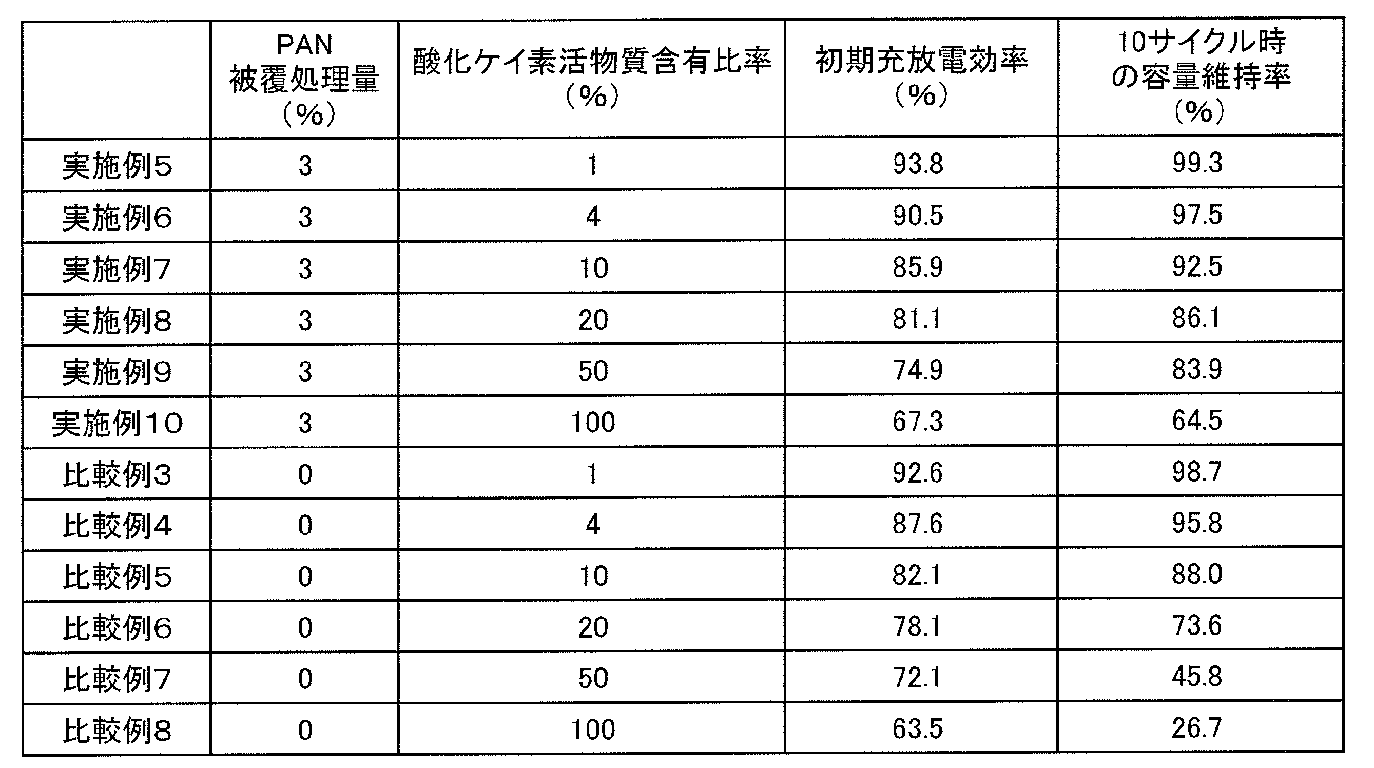
- Table 2 shows the amount of PAN coating treatment (mass%) of the silicon oxide active material in the negative electrodes of Examples 5 to 10 and Comparative Examples 3 to 8, the initial charge / discharge efficiency, and the capacity retention rate at 10 cycles.
- the content of the silicon oxide active material is preferably in the range of 1 to 100% by mass, more preferably in the range of 1 to 50% by mass with respect to the total mass with graphite. It can be seen that it is.
- the sheet was impregnated with the above electrolyte at 60 ° C. for 2 days. After impregnation, the sheet was taken out from the electrolytic solution, and the mass was measured. The liquid content was measured by the following formula, and the measurement results are shown in Table 3.
- Liquid content (%) (mass after impregnation ⁇ mass after drying) / mass after impregnation
- Reference Example 2 The liquid content was measured in the same manner as in Reference Example 1 except that the heat treatment was performed at 150 ° C. for 10 hours in a vacuum atmosphere instead of drying at 105 ° C. for 2 hours.
- deCN is generated by heat treatment of polyacrylonitrile and its modified product. Such de-CNification is thought to reduce the liquid content of the non-aqueous electrolyte.
Landscapes
- Chemical & Material Sciences (AREA)
- Chemical Kinetics & Catalysis (AREA)
- Electrochemistry (AREA)
- General Chemical & Material Sciences (AREA)
- Engineering & Computer Science (AREA)
- Composite Materials (AREA)
- Manufacturing & Machinery (AREA)
- Materials Engineering (AREA)
- Battery Electrode And Active Subsutance (AREA)
Abstract
Description
(実施例1)
〔酸化ケイ素の被覆〕
平均粒子径が5.3μmの酸化ケイ素SiOを用いた。この酸化ケイ素とポリアクリロニトリル(PAN)を質量比(SiO:PAN)が97:3となるようにN-メチル-2-ピロリドン(NMP)中で混合した。SiO及びPANのNMP中の固形分濃度は75質量%とした。
上記PANで被覆した酸化ケイ素活物質と、黒鉛とを、質量比(黒鉛:酸化ケイ素活物質)が96:4となるように混合して、この混合物を負極活物質として用いた。この負極活物質と、カルボキシメチルセルロース(CMC)と、スチレン-ブタジエンラテックス(SBR)とを、質量比(負極活物質:CMC:SBR)が97.5:1:1.5となるように水中で混合し、負極合剤スラリーを調製した。
正極活物質としてコバルト酸リチウム、炭素導電剤としてアセチレンブラック、結着剤としてポリフッ化ビニリデン(PVdF)を用いた。溶媒としてのNMP中で、これらを、質量比(コバルト酸リチウム:アセチレンブラック:PVdF)で95:2.5:2.5となるように混合し、正極合剤スラリーを調製した。なお、混合機としては、プライミクス社製コンビミックスを用いた。
エチレンカーボネート(EC)、フルオロエチレンカーボネート(FEC)、及びメチルエチルカーボネート(MEC)を、容積比(EC:FEC:MEC)で29:1:70となるように混合し、混合溶媒として用いた。この混合溶媒に、六フッ化リン酸リチウム(LiPF6)を1.0モル/リットルとなるように溶解して、非水電解液を調製した。
上記正極と、上記負極との間に、ポリエチレンからなるセパレータを介して対向させ、対向させたものを渦巻き状に捲回して電極体とした。正極タブ及び負極タブは、各電極内における最外周部に位置するように配置した。この渦巻状の電極体を押し潰して、扁平型の電極体を作製した。
酸化ケイ素とPANを質量比(SiO:PAN)が98:2となるように混合した混合物を負極活物質として用いる以外は、実施例1と同様にして試験用電池を作製した。
酸化ケイ素とPANを質量比(SiO:PAN)が99:1となるように混合した混合物を負極活物質として用いる以外は、実施例1と同様にして試験用電池を作製した。
NMP中で酸化ケイ素とPANを攪拌混合する際の固形分濃度を90質量%とする以外は、実施例1と同様にして酸化ケイ素活物質を作製し、この酸化ケイ素活物質を用いて実施例1と同様にして試験用電池を作製した。
酸化ケイ素活物質として、PANを被覆せずにそのまま酸化ケイ素を用いた以外は、実施例1と同様にして負極を作製し、この負極を用いて試験用電池を作製した。
酸化ケイ素の表面をPANで被覆した後、熱処理を行わなかったものを、酸化ケイ素活物質として用いた以外は、実施例1と同様にして負極を作製し、この負極を用いて試験用電池を作製した。
以下の充放電条件で、各試験用電池を充放電させ、各試験用電池の初期充放電効率及び300サイクル時の容量維持率を測定した。
1It(800mA)の電流で4.2Vになるまで定電流充電を行い、4.2Vの定電圧で電流1/20It(40mA)になるまで充電した。
・放電条件
1It(800mA)の電流で2.75Vになるまで定電流放電を行った。
・休止
充電と放電の間隔を10分間とした。
300サイクル時の容量維持率(%)=〔(300サイクル目の放電容量)/(1サイクル目の放電容量)〕×100

(実施例5)
上記PANで被覆した酸化ケイ素活物質と、黒鉛とを、質量比(黒鉛:酸化ケイ素活物質)が99:1となるように混合したこと以外は、実施例1と同様にして負極を作製した。
対極であるリチウム金属箔と、上記負極との間に、ポリエチレンからなるセパレータを介して対向させ、対向させたものを渦巻き状に捲回して電極体とした。対極タブ及び負極タブは、各電極内における最外周部に位置するように配置した。
上記PANで被覆した酸化ケイ素と、黒鉛とを、質量比(黒鉛:酸化ケイ素活物質)が96:4となるように混合して負極を作製する以外は、実施例5と同様にして試験用電池を作製した。
上記PANで被覆した酸化ケイ素と、黒鉛とを、質量比(黒鉛:酸化ケイ素活物質)が90:10となるように混合して負極を作製する以外は、実施例5と同様にして試験用電池を作製した。
上記PANで被覆した酸化ケイ素と、黒鉛とを、質量比(黒鉛:酸化ケイ素活物質)が80:20となるように混合して負極を作製する以外は、実施例5と同様にして試験用電池を作製した。
上記PANで被覆した酸化ケイ素と、黒鉛とを、質量比(黒鉛:酸化ケイ素活物質)が50:50となるように混合して負極を作製する以外は、実施例5と同様にして試験用電池を作製した。
上記PANで被覆した酸化ケイ素と、黒鉛とを、質量比(黒鉛:酸化ケイ素活物質)が0:100となるように混合して負極を作製する以外は、実施例5と同様にして試験用電池を作製した。
酸化ケイ素活物質として、PANを被覆せずにそのまま酸化ケイ素を用いた以外は、実施例5と同様にして試験用電池を作製した。
酸化ケイ素活物質として、PANを被覆せずにそのまま酸化ケイ素を用いた以外は、実施例6と同様にして試験用電池を作製した。
酸化ケイ素活物質として、PANを被覆せずにそのまま酸化ケイ素を用いた以外は、実施例7と同様にして試験用電池を作製した。
酸化ケイ素活物質として、PANを被覆せずにそのまま酸化ケイ素を用いた以外は、実施例8と同様にして試験用電池を作製した。
酸化ケイ素活物質として、PANを被覆せずにそのまま酸化ケイ素を用いた以外は、実施例9と同様にして試験用電池を作製した。
酸化ケイ素活物質として、PANを被覆せずにそのまま酸化ケイ素を用いた以外は、実施例10と同様にして試験用電池を作製した。
以下の充放電条件で、各試験用電池を充放電させ、各試験用電池の初期充放電効率及び10サイクル時の容量維持率を測定した。
0.1It(7mA)の電流で0Vになるまで定電流充電を行った。
・放電条件
0.1It(7mA)の電流で1Vになるまで定電流放電を行った。
・休止
充電と放電の間隔を10分間とした。
10サイクル時の容量維持率(%)=〔(10サイクル目の放電容量)/(1サイクル目の放電容量)〕×100
(参考例1)
上記実施例において用いたポリアクリロニトリル(PAN)をシート状に成型し、室温で乾燥した後、2cm×5cmの大きさに切り抜いた。切り抜いたシートを、真空雰囲気下で105℃で2時間乾燥した後、重量を測定した。
105℃で2時間の乾燥に代えて、真空雰囲気下で150℃で10時間熱処理したこと以外は、参考例1と同様にして、含液率を測定した。
105℃で2時間の乾燥に代えて、真空雰囲気下で190℃で10時間熱処理したこと以外は、参考例1と同様にして、含液率を測定した。

2…酸化ケイ素
3…熱処理したポリアクリロニトリルまたはその変性体
4…黒鉛
5…結着剤
Claims (9)
- 酸化ケイ素の表面を、熱処理が施されたポリアクリロニトリルまたはその変性体で被覆した非水電解質二次電池用活物質。
- 前記ポリアクリロニトリルまたはその変性体の被覆量が、前記酸化ケイ素との合計質量に対して、0.5~5.0質量%の範囲である請求項1に記載の非水電解質二次電池用活物質。
- 請求項1または2に記載の非水電解質二次電池用活物質を製造する方法であって、
前記酸化ケイ素の表面を、前記ポリアクリロニトリルまたはその変性体で被覆する工程と、
前記酸化ケイ素の表面を被覆したポリアクリロニトリルまたはその変性体を熱処理する工程とを備える非水電解質二次電池用活物質の製造方法。 - 前記熱処理の温度が、130~400℃の範囲内である請求項3に記載の非水電解質二次電池用活物質の製造方法。
- 請求項1または2に記載の非水電解質二次電池用活物質及び黒鉛を負極活物質として含み、結着剤を含む非水電解質二次電池用負極。
- 前記結着剤が、カルボキシメチルセルロース及びスチレン-ブタジエンラテックスである請求項5に記載の非水電解質二次電池用負極。
- 前記非水電解質二次電池用活物質の含有量が、前記黒鉛との合計質量に対して、1~100質量%の範囲内である請求項5または6に記載の非水電解質二次電池用負極。
- 前記非水電解質二次電池用活物質の含有量が、前記黒鉛との合計質量に対して、1~50質量%の範囲内である請求項5または6に記載の非水電解質二次電池用負極。
- 請求項5~8のいずれか1項に記載の負極と、正極と、非水電解質とを備える非水電解質二次電池。
Priority Applications (2)
| Application Number | Priority Date | Filing Date | Title |
|---|---|---|---|
| US14/130,564 US20140127576A1 (en) | 2011-07-29 | 2012-07-03 | Active material for nonaqueous electrolyte secondary batteries, method for producing the same, and negative electrode including the same |
| CN201280036244.4A CN103688395A (zh) | 2011-07-29 | 2012-07-03 | 非水电解质二次电池用活性物质及其制造方法以及使用其的负极 |
Applications Claiming Priority (4)
| Application Number | Priority Date | Filing Date | Title |
|---|---|---|---|
| JP2011166172 | 2011-07-29 | ||
| JP2011-166172 | 2011-07-29 | ||
| JP2011-211013 | 2011-09-27 | ||
| JP2011211013 | 2011-09-27 |
Publications (1)
| Publication Number | Publication Date |
|---|---|
| WO2013018486A1 true WO2013018486A1 (ja) | 2013-02-07 |
Family
ID=47629018
Family Applications (1)
| Application Number | Title | Priority Date | Filing Date |
|---|---|---|---|
| PCT/JP2012/066959 Ceased WO2013018486A1 (ja) | 2011-07-29 | 2012-07-03 | 非水電解質二次電池用活物質及びその製造方法並びにそれを用いた負極 |
Country Status (4)
| Country | Link |
|---|---|
| US (1) | US20140127576A1 (ja) |
| JP (1) | JPWO2013018486A1 (ja) |
| CN (1) | CN103688395A (ja) |
| WO (1) | WO2013018486A1 (ja) |
Cited By (17)
| Publication number | Priority date | Publication date | Assignee | Title |
|---|---|---|---|---|
| WO2014132579A1 (ja) * | 2013-02-26 | 2014-09-04 | 三洋電機株式会社 | 非水電解質二次電池用負極及び非水電解質二次電池 |
| US20140272571A1 (en) * | 2013-03-15 | 2014-09-18 | Physical Sciences, Inc. | Electroactive Polymer Coating for Improved Battery Safety |
| WO2015098023A1 (ja) * | 2013-12-26 | 2015-07-02 | 三洋電機株式会社 | 非水電解質二次電池用負極 |
| KR20160037006A (ko) * | 2014-09-26 | 2016-04-05 | 삼성전자주식회사 | 음극 활물질 및 이를 채용한 리튬 전지, 및 상기 음극 활물질의 제조방법 |
| CN105849945A (zh) * | 2013-12-26 | 2016-08-10 | 三洋电机株式会社 | 非水电解质二次电池用负极 |
| CN105849954A (zh) * | 2013-12-27 | 2016-08-10 | 三洋电机株式会社 | 非水电解质二次电池用负极 |
| KR20170121192A (ko) * | 2015-01-30 | 2017-11-01 | 더 리젠츠 오브 더 유니버시티 오브 콜로라도, 어 바디 코퍼레이트 | 이온화된 액체-작용 고-에너지 리튬 이온 배터리 |
| US10270086B2 (en) * | 2014-01-31 | 2019-04-23 | Sanyo Electric Co., Ltd. | Nonaqueous-electrolyte secondary-battery negative electrode |
| JP2019075239A (ja) * | 2017-10-13 | 2019-05-16 | トヨタ自動車株式会社 | 負極、およびそれを備える非水電解質二次電池 |
| KR102334001B1 (ko) * | 2020-11-17 | 2021-12-02 | 연세대학교 산학협력단 | 실리콘/고분자 복합나노입자, 이를 포함하는 리튬이차전지용 음극 및 상기 실리콘/고분자 복합나노입자의 제조방법 |
| KR20220008055A (ko) * | 2020-07-13 | 2022-01-20 | 한국기계연구원 | 음극 활물질 및 이를 이용한 전극 제조방법 |
| KR20220031656A (ko) * | 2019-07-29 | 2022-03-11 | 컨템포러리 엠퍼렉스 테크놀로지 씨오., 리미티드 | 부극 활성 재료, 그 제조 방법, 이차 전지 및 그 관련 전지 모듈, 전지 팩과 장치 |
| KR20220031914A (ko) * | 2019-07-29 | 2022-03-14 | 컨템포러리 엠퍼렉스 테크놀로지 씨오., 리미티드 | 부극 활성 재료, 그 제조 방법, 이차 전지 및 그 관련 전지 모듈, 전지 팩과 장치 |
| JP2022103379A (ja) * | 2013-03-27 | 2022-07-07 | 三菱ケミカル株式会社 | 非水系電解液及びそれを用いた非水系電解液電池 |
| WO2023018156A1 (ko) * | 2021-08-10 | 2023-02-16 | 네오 배터리 머티리얼즈 엘티디 | 비탄소계 나노입자 및 탄화층을 포함하는 복합 나노입자, 이를 포함하는 리튬 이차전지용 음극, 및 이의 제조방법 |
| KR20230023529A (ko) * | 2021-08-10 | 2023-02-17 | 네오 배터리 머티리얼즈 엘티디 | 비탄소계 나노입자 및 탄화층을 포함하는 복합 나노입자, 이를 포함하는 리튬 이차전지용 음극, 및 이의 제조방법 |
| JP2025523168A (ja) * | 2022-07-21 | 2025-07-17 | サイオニック エナジー, インコーポレイテッド | シリコンアノードベースのリチウムイオン電池 |
Families Citing this family (10)
| Publication number | Priority date | Publication date | Assignee | Title |
|---|---|---|---|---|
| US10553860B2 (en) * | 2014-06-20 | 2020-02-04 | Sumitomo Metal Mining Co., Ltd. | Covered lithium-nickel composite oxide particles, and method for manufacturing covered lithium-nickel composite oxide particles |
| KR102471728B1 (ko) * | 2014-10-24 | 2022-11-29 | 가부시키가이샤 한도오따이 에네루기 켄큐쇼 | 이차 전지, 및 이차 전지의 제작 방법 |
| CN104916821B (zh) * | 2015-05-12 | 2018-08-03 | 北京理工大学 | 一种新型锂离子电池用一氧化硅基负极材料及其制备方法和应用 |
| CN106058167A (zh) * | 2016-02-03 | 2016-10-26 | 万向A二三系统有限公司 | 一种多孔硅基合金复合材料 |
| CN110447127A (zh) * | 2017-03-20 | 2019-11-12 | 罗伯特·博世有限公司 | 电极活性材料、制备所述电极活性材料的方法以及包含所述电极活性材料的正极和电池 |
| US10873075B2 (en) * | 2017-09-01 | 2020-12-22 | Nanograf Corporation | Composite anode material including particles having buffered silicon-containing core and graphene-containing shell |
| CN112310359B (zh) | 2019-07-29 | 2024-01-12 | 宁德时代新能源科技股份有限公司 | 负极活性材料及二次电池 |
| CN112310360A (zh) * | 2019-07-29 | 2021-02-02 | 宁德时代新能源科技股份有限公司 | 负极活性材料及电池 |
| EP3913708A4 (en) | 2019-12-03 | 2022-03-30 | Contemporary Amperex Technology Co., Limited | COMPOSITE GRAPHITE MATERIAL, METHOD OF PRODUCTION, SECONDARY BATTERY AND DEVICE |
| WO2024049176A1 (ko) * | 2022-08-31 | 2024-03-07 | 주식회사 엘지에너지솔루션 | 음극 활물질 입자, 상기 음극 활물질 입자를 포함하는 음극, 및 상기 음극을 포함하는 이차 전지 |
Citations (4)
| Publication number | Priority date | Publication date | Assignee | Title |
|---|---|---|---|---|
| JPH06325765A (ja) * | 1992-07-29 | 1994-11-25 | Seiko Instr Inc | 非水電解質二次電池及びその製造方法 |
| JP2002042806A (ja) * | 2000-07-19 | 2002-02-08 | Japan Storage Battery Co Ltd | 非水電解質二次電池 |
| JP2010212228A (ja) * | 2009-02-13 | 2010-09-24 | Hitachi Maxell Ltd | 非水二次電池 |
| JP2011090869A (ja) * | 2009-10-22 | 2011-05-06 | Shin-Etsu Chemical Co Ltd | 非水電解質二次電池用負極材料、非水電解質二次電池用負極材の製造方法並びに非水電解質二次電池用負極及び非水電解質二次電池 |
Family Cites Families (8)
| Publication number | Priority date | Publication date | Assignee | Title |
|---|---|---|---|---|
| JP2004063433A (ja) * | 2001-12-26 | 2004-02-26 | Shin Etsu Chem Co Ltd | 導電性酸化珪素粉末、その製造方法及び該粉末を用いた非水電解質二次電池用負極材 |
| KR100918050B1 (ko) * | 2007-10-02 | 2009-09-18 | 삼성에스디아이 주식회사 | 리튬 이차 전지용 음극 활물질, 이를 포함하는 리튬 이차전지용 음극, 및 리튬 이차 전지 |
| JP2009117159A (ja) * | 2007-11-06 | 2009-05-28 | Sony Corp | 正極及びリチウムイオン二次電池 |
| JP5482660B2 (ja) * | 2008-09-30 | 2014-05-07 | 住友ベークライト株式会社 | リチウム二次電池負極用炭素材、リチウム二次電池負極、リチウム二次電池およびリチウム二次電池負極用炭素材の製造方法 |
| KR101802342B1 (ko) * | 2008-11-13 | 2017-11-28 | 삼성에스디아이 주식회사 | 유기전해액 및 이를 채용한 리튬전지 |
| CN102362384B (zh) * | 2009-09-01 | 2013-10-09 | 日立车辆能源株式会社 | 非水电解质二次电池 |
| JP5593663B2 (ja) * | 2009-09-29 | 2014-09-24 | 住友ベークライト株式会社 | リチウム二次電池負極合剤、リチウム二次電池負極およびリチウム二次電池 |
| US9601228B2 (en) * | 2011-05-16 | 2017-03-21 | Envia Systems, Inc. | Silicon oxide based high capacity anode materials for lithium ion batteries |
-
2012
- 2012-07-03 WO PCT/JP2012/066959 patent/WO2013018486A1/ja not_active Ceased
- 2012-07-03 CN CN201280036244.4A patent/CN103688395A/zh active Pending
- 2012-07-03 JP JP2013526788A patent/JPWO2013018486A1/ja active Pending
- 2012-07-03 US US14/130,564 patent/US20140127576A1/en not_active Abandoned
Patent Citations (4)
| Publication number | Priority date | Publication date | Assignee | Title |
|---|---|---|---|---|
| JPH06325765A (ja) * | 1992-07-29 | 1994-11-25 | Seiko Instr Inc | 非水電解質二次電池及びその製造方法 |
| JP2002042806A (ja) * | 2000-07-19 | 2002-02-08 | Japan Storage Battery Co Ltd | 非水電解質二次電池 |
| JP2010212228A (ja) * | 2009-02-13 | 2010-09-24 | Hitachi Maxell Ltd | 非水二次電池 |
| JP2011090869A (ja) * | 2009-10-22 | 2011-05-06 | Shin-Etsu Chemical Co Ltd | 非水電解質二次電池用負極材料、非水電解質二次電池用負極材の製造方法並びに非水電解質二次電池用負極及び非水電解質二次電池 |
Cited By (42)
| Publication number | Priority date | Publication date | Assignee | Title |
|---|---|---|---|---|
| CN105074975B (zh) * | 2013-02-26 | 2018-04-03 | 三洋电机株式会社 | 非水电解质二次电池用负极以及非水电解质二次电池 |
| CN105074975A (zh) * | 2013-02-26 | 2015-11-18 | 三洋电机株式会社 | 非水电解质二次电池用负极以及非水电解质二次电池 |
| WO2014132579A1 (ja) * | 2013-02-26 | 2014-09-04 | 三洋電機株式会社 | 非水電解質二次電池用負極及び非水電解質二次電池 |
| US10056606B2 (en) | 2013-02-26 | 2018-08-21 | Sanyo Electric Co., Ltd. | Negative electrode for nonaqueous electrolyte secondary battery and nonaqueous electrolyte secondary battery |
| JPWO2014132579A1 (ja) * | 2013-02-26 | 2017-02-02 | 三洋電機株式会社 | 非水電解質二次電池用負極及び非水電解質二次電池 |
| US20140272571A1 (en) * | 2013-03-15 | 2014-09-18 | Physical Sciences, Inc. | Electroactive Polymer Coating for Improved Battery Safety |
| JP2024113006A (ja) * | 2013-03-27 | 2024-08-21 | 三菱ケミカル株式会社 | 非水系電解液及びそれを用いた非水系電解液電池 |
| JP2022103379A (ja) * | 2013-03-27 | 2022-07-07 | 三菱ケミカル株式会社 | 非水系電解液及びそれを用いた非水系電解液電池 |
| JP7759434B2 (ja) | 2013-03-27 | 2025-10-23 | 三菱ケミカル株式会社 | 非水系電解液及びそれを用いた非水系電解液電池 |
| US10319993B2 (en) | 2013-12-26 | 2019-06-11 | Sanyo Electric Co., Ltd. | Negative electrode for non-aqueous electrolyte secondary battery |
| CN105849944A (zh) * | 2013-12-26 | 2016-08-10 | 三洋电机株式会社 | 非水电解质二次电池用负极 |
| WO2015098023A1 (ja) * | 2013-12-26 | 2015-07-02 | 三洋電機株式会社 | 非水電解質二次電池用負極 |
| JPWO2015098023A1 (ja) * | 2013-12-26 | 2017-03-23 | 三洋電機株式会社 | 非水電解質二次電池用負極 |
| CN105849945A (zh) * | 2013-12-26 | 2016-08-10 | 三洋电机株式会社 | 非水电解质二次电池用负极 |
| CN105849954A (zh) * | 2013-12-27 | 2016-08-10 | 三洋电机株式会社 | 非水电解质二次电池用负极 |
| CN105849954B (zh) * | 2013-12-27 | 2019-03-19 | 三洋电机株式会社 | 非水电解质二次电池用负极 |
| US10243205B2 (en) | 2013-12-27 | 2019-03-26 | Sanyo Electric Co., Ltd. | Negative electrode for non-aqueous electrolyte secondary batteries |
| US10270086B2 (en) * | 2014-01-31 | 2019-04-23 | Sanyo Electric Co., Ltd. | Nonaqueous-electrolyte secondary-battery negative electrode |
| KR102287812B1 (ko) * | 2014-09-26 | 2021-08-09 | 삼성전자주식회사 | 음극 활물질 및 이를 채용한 리튬 전지, 및 상기 음극 활물질의 제조방법 |
| KR20160037006A (ko) * | 2014-09-26 | 2016-04-05 | 삼성전자주식회사 | 음극 활물질 및 이를 채용한 리튬 전지, 및 상기 음극 활물질의 제조방법 |
| KR102585161B1 (ko) * | 2015-01-30 | 2023-10-04 | 더 리젠츠 오브 더 유니버시티 오브 콜로라도, 어 바디 코퍼레이트 | 이온화된 액체-작용 고-에너지 리튬 이온 배터리 |
| JP2018503962A (ja) * | 2015-01-30 | 2018-02-08 | ザ リージェンツ オブ ザ ユニバーシティ オブ コロラド,ア ボディー コーポレイトTHE REGENTS OF THE UNIVERSITY OF COLORADO,a body corporate | イオン性の液体使用可能な高エネルギーリチウムイオンバッテリ |
| KR20170121192A (ko) * | 2015-01-30 | 2017-11-01 | 더 리젠츠 오브 더 유니버시티 오브 콜로라도, 어 바디 코퍼레이트 | 이온화된 액체-작용 고-에너지 리튬 이온 배터리 |
| JP2019075239A (ja) * | 2017-10-13 | 2019-05-16 | トヨタ自動車株式会社 | 負極、およびそれを備える非水電解質二次電池 |
| KR20220031656A (ko) * | 2019-07-29 | 2022-03-11 | 컨템포러리 엠퍼렉스 테크놀로지 씨오., 리미티드 | 부극 활성 재료, 그 제조 방법, 이차 전지 및 그 관련 전지 모듈, 전지 팩과 장치 |
| KR20220031914A (ko) * | 2019-07-29 | 2022-03-14 | 컨템포러리 엠퍼렉스 테크놀로지 씨오., 리미티드 | 부극 활성 재료, 그 제조 방법, 이차 전지 및 그 관련 전지 모듈, 전지 팩과 장치 |
| JP2022542274A (ja) * | 2019-07-29 | 2022-09-30 | 寧徳時代新能源科技股▲分▼有限公司 | 負極活性材料、その調製方法、二次電池及びその関連の電池モジュール、電池パック並びに装置 |
| JP2022542278A (ja) * | 2019-07-29 | 2022-09-30 | 寧徳時代新能源科技股▲分▼有限公司 | 負極活性材料、その調製方法、二次電池及びその関連の電池モジュール、電池パック並びに装置 |
| KR102673319B1 (ko) * | 2019-07-29 | 2024-06-12 | 컨템포러리 엠퍼렉스 테크놀로지 씨오., 리미티드 | 부극 활성 재료, 그 제조 방법, 이차 전지 및 그 관련 전지 모듈, 전지 팩과 장치 |
| JP7289986B2 (ja) | 2019-07-29 | 2023-06-12 | 寧徳時代新能源科技股▲分▼有限公司 | 負極活性材料、その調製方法、二次電池及びその関連の電池モジュール、電池パック並びに装置 |
| JP7313539B2 (ja) | 2019-07-29 | 2023-07-24 | 寧徳時代新能源科技股▲分▼有限公司 | 負極活性材料、その調製方法、二次電池及びその関連の電池モジュール、電池パック並びに装置 |
| US11996548B2 (en) | 2019-07-29 | 2024-05-28 | Contemporary Amperex Technology Co., Limited | Negative active material, preparation method thereof, secondary battery and related battery module, battery pack and device |
| KR102633438B1 (ko) * | 2019-07-29 | 2024-02-06 | 컨템포러리 엠퍼렉스 테크놀로지 씨오., 리미티드 | 부극 활성 재료, 그 제조 방법, 이차 전지 및 그 관련 전지 모듈, 전지 팩과 장치 |
| US11973215B2 (en) | 2019-07-29 | 2024-04-30 | Contemporary Amperex Technology Co., Limited | Negative active material, preparation method thereof, secondary battery and related battery module, battery pack and device |
| KR102464325B1 (ko) * | 2020-07-13 | 2022-11-08 | 한국기계연구원 | 음극 활물질 및 이를 이용한 전극 제조방법 |
| KR20220008055A (ko) * | 2020-07-13 | 2022-01-20 | 한국기계연구원 | 음극 활물질 및 이를 이용한 전극 제조방법 |
| KR102334001B1 (ko) * | 2020-11-17 | 2021-12-02 | 연세대학교 산학협력단 | 실리콘/고분자 복합나노입자, 이를 포함하는 리튬이차전지용 음극 및 상기 실리콘/고분자 복합나노입자의 제조방법 |
| WO2022108132A1 (ko) * | 2020-11-17 | 2022-05-27 | 연세대학교 산학협력단 | 비탄소 나노입자/고분자 복합나노입자, 이를 포함하는 리튬이차전지용 음극 및 상기 비탄소 나노입자/고분자 복합나노입자의 제조방법 |
| KR20230023529A (ko) * | 2021-08-10 | 2023-02-17 | 네오 배터리 머티리얼즈 엘티디 | 비탄소계 나노입자 및 탄화층을 포함하는 복합 나노입자, 이를 포함하는 리튬 이차전지용 음극, 및 이의 제조방법 |
| WO2023018156A1 (ko) * | 2021-08-10 | 2023-02-16 | 네오 배터리 머티리얼즈 엘티디 | 비탄소계 나노입자 및 탄화층을 포함하는 복합 나노입자, 이를 포함하는 리튬 이차전지용 음극, 및 이의 제조방법 |
| KR102799895B1 (ko) * | 2021-08-10 | 2025-04-29 | 네오 배터리 머티리얼즈 엘티디 | 비탄소계 나노입자 및 탄화층을 포함하는 복합 나노입자, 이를 포함하는 리튬 이차전지용 음극, 및 이의 제조방법 |
| JP2025523168A (ja) * | 2022-07-21 | 2025-07-17 | サイオニック エナジー, インコーポレイテッド | シリコンアノードベースのリチウムイオン電池 |
Also Published As
| Publication number | Publication date |
|---|---|
| CN103688395A (zh) | 2014-03-26 |
| JPWO2013018486A1 (ja) | 2015-03-05 |
| US20140127576A1 (en) | 2014-05-08 |
Similar Documents
| Publication | Publication Date | Title |
|---|---|---|
| JPWO2013018486A1 (ja) | 非水電解質二次電池用活物質及びその製造方法並びにそれを用いた負極 | |
| JP5924552B2 (ja) | 非水電解液二次電池とその製造方法 | |
| JP5209964B2 (ja) | リチウム二次電池 | |
| CN101320822B (zh) | 非水电解质二次电池及非水电解质二次电池用正极的制造方法 | |
| CN103931030B (zh) | 锂离子二次电池及其制造方法 | |
| CN112467209A (zh) | 一种高低温性能兼顾的高电压锂离子电池 | |
| JP6011785B2 (ja) | 非水電解質二次電池用正極活物質およびその製造方法 | |
| EP3373366B1 (en) | Electrode for non-aqueous electrolyte secondary battery | |
| JP2010267475A (ja) | リチウムイオン二次電池 | |
| JP2008226605A (ja) | 非水電解質二次電池 | |
| CN112420980B (zh) | 锂离子二次电池用电极和锂离子二次电池 | |
| CN108807863A (zh) | 改性正极活性材料及其制备方法及电化学储能装置 | |
| CN105074975B (zh) | 非水电解质二次电池用负极以及非水电解质二次电池 | |
| CN101405898A (zh) | 非水电解质二次电池 | |
| US20130337324A1 (en) | Nonaqueous electrolyte secondary battery and method for manufacturing same | |
| JP2014096238A (ja) | 蓄電デバイス用正極の製造方法、及び正極 | |
| CN103210529B (zh) | 非水电解质二次电池及其制造方法 | |
| JP5783029B2 (ja) | 非水電解質二次電池用の負極とその製造方法、及び非水電解質二次電池 | |
| CN114097108A (zh) | 负极材料及其制备方法、电化学装置及电子装置 | |
| JP2011192561A (ja) | 非水電解液二次電池の製造方法 | |
| JP7125655B2 (ja) | 負極 | |
| JP2014067490A (ja) | 非水電解質二次電池 | |
| JP5920666B2 (ja) | 非水電解質二次電池用正極活物質およびその製造方法 | |
| JP6457272B2 (ja) | 二次電池の充電ムラ低減方法及び二次電池の製造方法 | |
| JP5296971B2 (ja) | 二次電池用負極の製造方法 |
Legal Events
| Date | Code | Title | Description |
|---|---|---|---|
| 121 | Ep: the epo has been informed by wipo that ep was designated in this application |
Ref document number: 12819368 Country of ref document: EP Kind code of ref document: A1 |
|
| ENP | Entry into the national phase |
Ref document number: 2013526788 Country of ref document: JP Kind code of ref document: A |
|
| WWE | Wipo information: entry into national phase |
Ref document number: 14130564 Country of ref document: US |
|
| NENP | Non-entry into the national phase |
Ref country code: DE |
|
| 122 | Ep: pct application non-entry in european phase |
Ref document number: 12819368 Country of ref document: EP Kind code of ref document: A1 |