WO2013005588A1 - 化学強化用フロートガラス - Google Patents
化学強化用フロートガラス Download PDFInfo
- Publication number
- WO2013005588A1 WO2013005588A1 PCT/JP2012/066064 JP2012066064W WO2013005588A1 WO 2013005588 A1 WO2013005588 A1 WO 2013005588A1 JP 2012066064 W JP2012066064 W JP 2012066064W WO 2013005588 A1 WO2013005588 A1 WO 2013005588A1
- Authority
- WO
- WIPO (PCT)
- Prior art keywords
- float glass
- depth
- glass
- top surface
- hydrogen concentration
- Prior art date
- Legal status (The legal status is an assumption and is not a legal conclusion. Google has not performed a legal analysis and makes no representation as to the accuracy of the status listed.)
- Ceased
Links
Images

Classifications
-
- C—CHEMISTRY; METALLURGY
- C03—GLASS; MINERAL OR SLAG WOOL
- C03C—CHEMICAL COMPOSITION OF GLASSES, GLAZES OR VITREOUS ENAMELS; SURFACE TREATMENT OF GLASS; SURFACE TREATMENT OF FIBRES OR FILAMENTS MADE FROM GLASS, MINERALS OR SLAGS; JOINING GLASS TO GLASS OR OTHER MATERIALS
- C03C21/00—Treatment of glass, not in the form of fibres or filaments, by diffusing ions or metals in the surface
- C03C21/001—Treatment of glass, not in the form of fibres or filaments, by diffusing ions or metals in the surface in liquid phase, e.g. molten salts, solutions
- C03C21/002—Treatment of glass, not in the form of fibres or filaments, by diffusing ions or metals in the surface in liquid phase, e.g. molten salts, solutions to perform ion-exchange between alkali ions
-
- C—CHEMISTRY; METALLURGY
- C03—GLASS; MINERAL OR SLAG WOOL
- C03C—CHEMICAL COMPOSITION OF GLASSES, GLAZES OR VITREOUS ENAMELS; SURFACE TREATMENT OF GLASS; SURFACE TREATMENT OF FIBRES OR FILAMENTS MADE FROM GLASS, MINERALS OR SLAGS; JOINING GLASS TO GLASS OR OTHER MATERIALS
- C03C3/00—Glass compositions
- C03C3/04—Glass compositions containing silica
- C03C3/076—Glass compositions containing silica with 40% to 90% silica, by weight
- C03C3/083—Glass compositions containing silica with 40% to 90% silica, by weight containing aluminium oxide or an iron compound
- C03C3/085—Glass compositions containing silica with 40% to 90% silica, by weight containing aluminium oxide or an iron compound containing an oxide of a divalent metal
- C03C3/087—Glass compositions containing silica with 40% to 90% silica, by weight containing aluminium oxide or an iron compound containing an oxide of a divalent metal containing calcium oxide, e.g. common sheet or container glass
-
- C—CHEMISTRY; METALLURGY
- C03—GLASS; MINERAL OR SLAG WOOL
- C03B—MANUFACTURE, SHAPING, OR SUPPLEMENTARY PROCESSES
- C03B18/00—Shaping glass in contact with the surface of a liquid
- C03B18/02—Forming sheets
-
- C—CHEMISTRY; METALLURGY
- C03—GLASS; MINERAL OR SLAG WOOL
- C03C—CHEMICAL COMPOSITION OF GLASSES, GLAZES OR VITREOUS ENAMELS; SURFACE TREATMENT OF GLASS; SURFACE TREATMENT OF FIBRES OR FILAMENTS MADE FROM GLASS, MINERALS OR SLAGS; JOINING GLASS TO GLASS OR OTHER MATERIALS
- C03C21/00—Treatment of glass, not in the form of fibres or filaments, by diffusing ions or metals in the surface
- C03C21/001—Treatment of glass, not in the form of fibres or filaments, by diffusing ions or metals in the surface in liquid phase, e.g. molten salts, solutions
- C03C21/006—Treatment of glass, not in the form of fibres or filaments, by diffusing ions or metals in the surface in liquid phase, e.g. molten salts, solutions to perform an exchange of the type Xn+ ----> nH+
-
- C—CHEMISTRY; METALLURGY
- C03—GLASS; MINERAL OR SLAG WOOL
- C03C—CHEMICAL COMPOSITION OF GLASSES, GLAZES OR VITREOUS ENAMELS; SURFACE TREATMENT OF GLASS; SURFACE TREATMENT OF FIBRES OR FILAMENTS MADE FROM GLASS, MINERALS OR SLAGS; JOINING GLASS TO GLASS OR OTHER MATERIALS
- C03C3/00—Glass compositions
- C03C3/04—Glass compositions containing silica
- C03C3/076—Glass compositions containing silica with 40% to 90% silica, by weight
- C03C3/083—Glass compositions containing silica with 40% to 90% silica, by weight containing aluminium oxide or an iron compound
- C03C3/085—Glass compositions containing silica with 40% to 90% silica, by weight containing aluminium oxide or an iron compound containing an oxide of a divalent metal
-
- C—CHEMISTRY; METALLURGY
- C03—GLASS; MINERAL OR SLAG WOOL
- C03C—CHEMICAL COMPOSITION OF GLASSES, GLAZES OR VITREOUS ENAMELS; SURFACE TREATMENT OF GLASS; SURFACE TREATMENT OF FIBRES OR FILAMENTS MADE FROM GLASS, MINERALS OR SLAGS; JOINING GLASS TO GLASS OR OTHER MATERIALS
- C03C4/00—Compositions for glass with special properties
- C03C4/18—Compositions for glass with special properties for ion-sensitive glass
-
- C—CHEMISTRY; METALLURGY
- C03—GLASS; MINERAL OR SLAG WOOL
- C03C—CHEMICAL COMPOSITION OF GLASSES, GLAZES OR VITREOUS ENAMELS; SURFACE TREATMENT OF GLASS; SURFACE TREATMENT OF FIBRES OR FILAMENTS MADE FROM GLASS, MINERALS OR SLAGS; JOINING GLASS TO GLASS OR OTHER MATERIALS
- C03C2204/00—Glasses, glazes or enamels with special properties
-
- Y—GENERAL TAGGING OF NEW TECHNOLOGICAL DEVELOPMENTS; GENERAL TAGGING OF CROSS-SECTIONAL TECHNOLOGIES SPANNING OVER SEVERAL SECTIONS OF THE IPC; TECHNICAL SUBJECTS COVERED BY FORMER USPC CROSS-REFERENCE ART COLLECTIONS [XRACs] AND DIGESTS
- Y02—TECHNOLOGIES OR APPLICATIONS FOR MITIGATION OR ADAPTATION AGAINST CLIMATE CHANGE
- Y02P—CLIMATE CHANGE MITIGATION TECHNOLOGIES IN THE PRODUCTION OR PROCESSING OF GOODS
- Y02P40/00—Technologies relating to the processing of minerals
- Y02P40/50—Glass production, e.g. reusing waste heat during processing or shaping
- Y02P40/57—Improving the yield, e-g- reduction of reject rates
Definitions
- the present invention relates to a float glass for chemical strengthening.
- a thin plate-like cover glass is formed on the front surface of the display so as to be wider than the image display portion in order to enhance the protection and aesthetics of the display. It has been done to arrange.
- Such a flat panel display device is required to be lightweight and thin, and accordingly, a cover glass used for display protection is also required to be thin.
- the float glass manufactured by the float process is chemically strengthened to form a compressive stress layer on the surface to enhance the scratch resistance of the cover glass.
- the surface compressive stress of chemically strengthened float glass chemically strengthened from conventional soda lime glass is about 500 MPa, and the depth of the compressive stress layer is about 10 ⁇ m.
- a chemically strengthened float glass having a compressive stress of 600 MPa or more and a compressive stress layer having a depth of 15 ⁇ m or more has been developed.
- Patent Document 1 It has been reported that the float glass is warped after chemical strengthening and the flatness is impaired (Patent Document 1).
- the warpage is caused by chemical strengthening between a glass surface that is not in contact with molten tin (hereinafter also referred to as a top surface) and a glass surface that is in contact with molten tin (hereinafter also referred to as a bottom surface) during float forming. This is caused by different entry.
- the surface compressive stress was developed to meet the demand for high scratch resistance, the surface compressive stress is 600 MPa or more, and the depth of the compressive stress layer is 15 ⁇ m or more.
- the problem of warpage becomes more obvious as compared with the conventional chemically strengthened float glass having a surface compressive stress of about 500 MPa and a depth of the compressive stress layer of about 10 ⁇ m.
- Patent Document 1 the plate-like body manufactured and processed by the float process is chemically polished after being immersed in or contacted with Li ions, Na ions, or a mixed inorganic salt thereof without polishing the surface. Improvements are disclosed.
- the strengthening stress due to chemical strengthening is reduced, or the top surface and the bottom surface of the float glass are subjected to grinding treatment or polishing treatment, and then chemically strengthened after removing the surface heterogeneous layer.
- Patent Document 1 it is necessary to immerse the float glass in the mixed inorganic salt before chemical strengthening, which is complicated. Moreover, there is a possibility that the strength of the float glass after chemical strengthening becomes insufficient by the method of reducing the strengthening stress.
- the method of grinding or polishing the top and bottom surfaces of the float glass before chemical strengthening has a problem from the viewpoint of improving productivity, and it is preferable to omit these grinding or polishing treatments. .
- an object of the present invention is to provide a float glass for chemical strengthening capable of effectively suppressing warpage after chemical strengthening and omitting or simplifying polishing treatment before chemical strengthening or the like. To do.
- the main reason for the difference in entering the chemical strengthening between the bottom surface and the top surface of the float glass is not the metal that has entered the glass surface that contacts the molten metal at the time of float forming, but the top surface. It was found that the hydrogen concentration was different from the bottom surface. Further, it has been found that by reducing the difference in hydrogen concentration, the ease of strengthening due to chemical strengthening between the top surface and the bottom surface can be balanced, and warpage of the float glass after chemical strengthening can be reduced. Furthermore, by measuring the surface layer ⁇ -OH, it was found that the error range of the hydrogen concentration on the bottom and top surfaces of the float glass can be evaluated more narrowly, and the present invention was completed based on these findings.
- the present invention is as follows. 1.
- a float glass for chemical strengthening having a bottom surface in contact with a molten metal at the time of molding and a top surface opposite to the bottom surface, wherein a hydrogen concentration at a depth of 5 to 10 ⁇ m is divided by a hydrogen concentration at a depth of 50 to 55 ⁇ m.
- a float glass for chemical strengthening in which the absolute value of the difference between the top surface and the bottom surface of the normalized hydrogen concentration at a depth of 5 to 10 ⁇ m is 0.35 or less.
- the hydrogen concentration at a depth of 5 to 10 ⁇ m and the hydrogen concentration at a depth of 50 to 55 ⁇ m are values (average values) measured under the following analytical conditions.
- Measuring device Secondary ion mass spectrometer having a quadrupole mass analyzer
- Primary ion species Cs +
- Primary acceleration voltage 5.0 kV
- Primary ion current 1 ⁇ A
- Primary ion incident angle (angle from the direction perpendicular to the sample surface): 60 °
- Raster size 200 ⁇ 200 ⁇ m 2
- Detection area 40 ⁇ 40 ⁇ m 2
- Secondary ion polarity Use of electron gun for negative neutralization 2.
- a float glass for chemical strengthening having a bottom surface in contact with a molten metal at the time of molding and a top surface facing the bottom surface up to a depth of 60 ⁇ m measured under the following analysis conditions using a secondary ion mass spectrometer is divided by the [- - / 30 Si 1 H ] [- - / 30 Si 1 H] at a depth 50 ⁇ 55 .mu.m in the profile depth of 5 ⁇ 10 ⁇ m [- - / 30 Si 1 H] of A float glass for chemical strengthening in which the absolute value of the difference between the top surface and the bottom surface is 0.35 or less with respect to the normalized strength at a depth of 5 to 10 ⁇ m.
- the [ 1 H ⁇ / 30 Si ⁇ ] profile is a ratio of the secondary ion intensity profile of hydrogen H and the secondary ion intensity profile of the silicon isotope 30 Si measured under the following analytical conditions,
- the normalized strength corresponds to the normalized hydrogen concentration.
- Measuring device Secondary ion mass spectrometer having a quadrupole mass analyzer
- Primary ion species Cs +
- Primary acceleration voltage 5.0 kV
- Primary ion current 1 ⁇ A
- Primary ion incident angle (angle from the direction perpendicular to the sample surface): 60 °
- Raster size 200 ⁇ 200 ⁇ m 2
- Detection area 40 ⁇ 40 ⁇ m 2
- Secondary ion polarity Use of electron gun for negative neutralization 3.
- a float glass for chemical strengthening having a bottom surface in contact with a molten metal at the time of molding and a top surface facing the bottom surface, the ratio of the bottom surface to the top surface having an average H / Si strength at a depth of 5 to 10 ⁇ m.
- Float glass for chemical strengthening that is 1.65 or less. 4).
- a chemically strengthened float glass having a bottom surface in contact with a molten metal during molding and a top surface opposite to the bottom surface, the ratio of the bottom surface to the top surface of the surface layer ⁇ -OH at a depth of 5 to 30 ⁇ m (bottom surface)
- Float glass for chemical strengthening having a surface layer ⁇ -OH / surface layer ⁇ -OH of 1.27 or less. 5.
- a float glass for chemical strengthening having a bottom surface in contact with a molten metal at the time of molding and a top surface facing the bottom surface, and is calculated by the following steps (1) to (3) at a depth of 5 to 30 ⁇ m.
- a float glass for chemical strengthening in which the ratio of the bottom surface to the top surface of the surface layer ⁇ -OH (the surface layer ⁇ -OH of the bottom surface / the surface layer ⁇ -OH of the top surface) is 1.27 or less.
- the measurement surface of the float glass is polished by 25 ⁇ m, and the absorbance of the Si—OH peak is measured in the same manner as in the step (1).
- the surface layer ⁇ -OH of the target region is calculated by the following equation from the difference in absorbance of the Si—OH peak before and after polishing obtained in steps (1) and (2) and the polishing thickness.
- (Surface layer ⁇ -OH) [(Si—OH absorbance of 5 ⁇ m polishing) ⁇ (Si—OH absorbance of 30 ⁇ m polishing)] / Polishing thickness (mm) 6).
- the absolute value of the difference between the top surface and the bottom surface of the normalized hydrogen concentration at a depth of 5 to 10 ⁇ m, which is a value obtained by dividing the hydrogen concentration at a depth of 50 to 55 ⁇ m by a hydrogen concentration, is 0.35 or less.
- the hydrogen concentration at a depth of 5 to 10 ⁇ m and the hydrogen concentration at a depth of 50 to 55 ⁇ m are values measured under the following analytical conditions.
- Measuring device Secondary ion mass spectrometer having a quadrupole mass analyzer
- Primary ion species Cs + Primary acceleration voltage: 5.0 kV
- Primary ion current 1 ⁇ A
- Primary ion incident angle (angle from the direction perpendicular to the sample surface): 60 °
- Raster size 200 ⁇ 200 ⁇ m 2
- Detection area 40 ⁇ 40 ⁇ m 2
- Secondary ion polarity Use of electron gun for negative neutralization
- a method for producing a chemically strengthened float glass by chemically strengthening a float glass having a bottom surface in contact with a molten metal at the time of molding and a top surface opposite to the bottom surface, wherein [ 1 H ⁇ / 30 of the float glass The value obtained by dividing [ 1 H ⁇ / 30 Si ⁇ ] at a depth of 5 ⁇ 10 ⁇ m of the Si ⁇ ] profile by [ 1 H ⁇ / 30 Si ⁇ ] at a depth of 50 to 55
- a method for producing chemically strengthened float glass characterized in that an absolute value of a difference between a top surface and a bottom surface of normalized strength at a depth of 5 to 10 ⁇ m is 0.35 or less.
- Measuring device Secondary ion mass spectrometer having a quadrupole mass analyzer
- Primary ion species Cs +
- Primary acceleration voltage 5.0 kV
- Primary ion current 1 ⁇ A
- Raster size 200 ⁇ 200 ⁇ m 2
- Detection area 40 ⁇ 40 ⁇ m 2
- Secondary ion polarity use of electron gun for negative neutralization
- a float glass for chemical strengthening having a bottom surface in contact with a molten metal at the time of molding and a top surface facing the bottom surface, the ratio of the bottom surface to the top surface having an average H / Si strength at a depth of 5 to 10 ⁇ m.
- the manufacturing method of the float glass for chemical strengthening which is 1.65 or less.
- the ratio of the bottom surface to the top surface of the surface layer ⁇ -OH in (the surface layer ⁇ -OH of the bottom surface / the surface layer ⁇ -OH of the top surface) is 1.27 or less.
- 10. 10 The method for producing chemically strengthened float glass according to any one of items 6 to 9, wherein the surface compressive stress of the chemically strengthened float glass is 600 MPa or more and the depth of the compressive stress layer is 15 ⁇ m or more.
- the float glass for chemical strengthening of the present invention has a small difference in hydrogen concentration between the top surface and the bottom surface, the stress due to chemical strengthening is not reduced, and the polishing treatment before chemical strengthening can be simplified or omitted.
- the curvature of the float glass after chemical strengthening can be reduced and excellent flatness can be obtained.
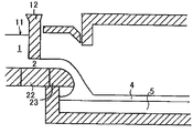
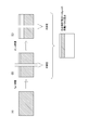
- FIG. 1 is a longitudinal sectional view of the apparatus for producing a chemically strengthened float glass of the present invention.
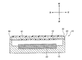
- FIG. 2 is a cross-sectional view of a flat panel display used as a cover glass for a flat panel display after chemically strengthening the chemically strengthened float glass of the present invention.
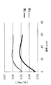
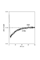
- FIG. 3 is a diagram showing a [ 1 H ⁇ / 30 Si ⁇ ] profile by secondary ion mass spectrometry of the float glass of Comparative Example 1 (glass material B). In the figure, the T surface is the top surface and the B surface is the bottom surface.
- FIG. 1 is a longitudinal sectional view of the apparatus for producing a chemically strengthened float glass of the present invention.
- FIG. 2 is a cross-sectional view of a flat panel display used as a cover glass for a flat panel display after chemically strengthening the chemically strengthened float glass of the present invention.
- FIG. 3 is a diagram showing a [ 1 H ⁇ / 30 Si ⁇ ] profile by secondary ion
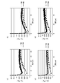
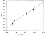
- FIGS. 5A to 5D are diagrams showing [ 1 H ⁇ / 30 Si ⁇ ] profiles by secondary ion mass spectrometry of the float glass used in the examples and comparative examples.
- FIG. 6 is a diagram showing an outline of the polishing IR method. In FIG. 7, ⁇ -OH is calculated for a region having a depth of 0 to 40 ⁇ m and compared with the 1H / 30Si average count of the region calculated by the SIMS method.
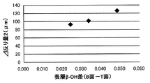
- FIG. 8 is a diagram showing the correlation between the surface layer ⁇ -OH and the ⁇ warpage amount 2 described later.
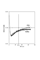
- FIG. 9 is a diagram showing an H / Si intensity profile measured under analysis condition A. (Example 3)
- FIG. 10 is a diagram showing an H / Si intensity profile measured under analysis condition B. (Example 3)
- the float glass for chemical strengthening according to the present invention is formed by a float process, and has a bottom surface that contacts a molten metal at the time of forming and a top surface that faces the bottom surface.
- the present inventors have found that the main cause of warpage caused by chemically strengthening the float glass is a difference in hydrogen concentration between the top surface and the bottom surface, as will be described below.
- molten glass is continuously supplied from the upstream side to the surface of the molten metal stored in the float bath, and a glass ribbon is formed while forming the glass ribbon from the downstream end of the float bath.
- a glass ribbon is drawn out and slowly cooled with a layer to produce a plate glass.
- an apparatus of a type in which a flow path is narrowed is generally used in which a glass tank kiln and a float bath are connected by a canal and a spout.
- molten glass having a higher temperature is poured out onto the surface of the molten metal as compared with another type of apparatus described later.
- the float glass produced by this type of apparatus has a lower hydrogen concentration on the surface (5 to 10 ⁇ m) than the hydrogen concentration inside (typically a depth of about 50 ⁇ m or more). Since the diffusion coefficient of H 2 O is higher at higher temperatures, the diffusion amount of H 2 O from the top surface in contact with an atmosphere having a lower dew point or higher temperature than the bottom surface of the float glass in contact with the lower temperature molten metal The hydrogen concentration on the top surface is lower than the bottom surface of the float glass.
- the molten glass at a lower temperature is poured into a molten metal at a higher temperature than the apparatus of the type described above and molded. Since the diffusion coefficient of H 2 O is higher when the temperature is higher, the temperature of the bottom surface may be higher than the top surface of the float glass. In such a case, the H 2 O concentration from the bottom surface may be higher than that of the top surface. The amount of diffusion increases, and the hydrogen concentration on the bottom surface is lower than the top surface of the float glass.
- the glass produced by the float process has a lower hydrogen concentration on the top surface than the bottom surface or a lower hydrogen concentration on the bottom surface than the top surface depending on the production conditions. A density difference occurs.
- the hydrogen concentration on the top surface is lower than the bottom surface of the float glass will be mainly described, but the present invention is not limited to this.
- the glass surface with a high hydrogen concentration is less stressed during chemical strengthening, and the glass surface with a lower hydrogen concentration is susceptible to stress during chemical strengthening. It will be.
- the glass when a float glass with a lower hydrogen concentration on the top surface than the bottom surface is chemically strengthened, the glass has a strong stress on the top surface with a lower hydrogen concentration than the bottom surface with a higher hydrogen concentration, and is convex toward the top surface. It is thought that warping occurs and warping occurs.
- the stress approaches to a state where the stresses are balanced, and the warpage is reduced.
- [ 1 H ⁇ / 30 Si ⁇ ] is a value measured under the following analytical conditions.
- Measuring device Secondary ion mass spectrometer having a quadrupole mass analyzer
- Primary ion species Cs +
- Primary acceleration voltage 5.0 kV
- Primary ion current 1 ⁇ A
- Primary ion incident angle (angle from the direction perpendicular to the sample surface): 60 °
- Raster size 200 ⁇ 200 ⁇ m 2
- Detection area 40 ⁇ 40 ⁇ m 2
- Secondary ion polarity Use of electron gun for negative neutralization
- the secondary ion intensity I M1 of the isotope M 1 of the element M in secondary ion mass spectrometry is the primary ion intensity I P , the sputtering rate Y of the matrix, the concentration M M of the element M (ratio to the total concentration), and the isotope M. It is proportional to the existence probability ⁇ 1 of 1 , the secondary ionization rate ⁇ M of the element M, and the transmission efficiency ⁇ (including the detection efficiency of the detector) of the mass spectrometer.
- I M1 A ⁇ I P ⁇ Y ⁇ C M ⁇ ⁇ 1 ⁇ ⁇ M ⁇ ⁇ (Formula 1)
- A is the ratio of the secondary ion detection area to the scanning range of the primary ion beam.
- ⁇ is eliminated by using a main component element or the like in the same sample as a reference element and taking a ratio with (Equation 1).
- 1 H ⁇ corresponds to M 1 and 30 Si ⁇ corresponds to R j . Therefore, from (Equation 2), the intensity ratio [ 1 H ⁇ / 30 Si ⁇ ] is equal to the hydrogen concentration C H divided by K. That is, [ 1 H ⁇ / 30 Si ⁇ ] is a direct indicator of the hydrogen concentration.
- the normalized strength is obtained by dividing [ 1 H ⁇ / 30 Si ⁇ ] at a certain depth x by [ 1 H ⁇ / 30 Si ⁇ ] at a depth of 50 to 55 ⁇ m, that is, C H / K at a certain depth x. It is a value divided by C H / K at a depth of 50 to 55 ⁇ m. K is the same as that obtained by dividing the C H at a depth 50 ⁇ 55 .mu.m a C H in the end normalized intensity because they are erased depth x, i.e., a normalized hydrogen concentration at the depth x.
- the absolute value of the difference in normalized strength between the top surface and the bottom surface in the float glass is determined by, for example, the following (i) to (iii) by secondary ion mass spectrometry (Secondary Ion Mass Spectrometry, SIMS analysis). The procedure is required.
- the analysis conditions shown below are examples, and should be changed as appropriate depending on the measurement device, sample, and the like.
- More specific analysis conditions are, for example, as follows.
- Measuring device Secondary ion mass spectrometer having a quadrupole mass analyzer
- Primary ion species Cs +
- Primary acceleration voltage 5.0 kV
- Primary ion current 1 ⁇ A
- Primary ion incident angle (angle from the direction perpendicular to the sample surface): 60 °
- Raster size 200 ⁇ 200 ⁇ m 2
- Detection area 40 ⁇ 40 ⁇ m 2
- Sputter rate 14 nm / sec
- Secondary ion polarity Use of electron gun for negative neutralization
- ADEPT 1010 manufactured by ULVAC-PHI can be mentioned.
- the absolute value of the difference between the top surface and the bottom surface is 0.35 or less with respect to the normalized strength or the normalized hydrogen concentration at a depth of 5 to 10 ⁇ m obtained by secondary ion mass spectrometry. 0.32 or less, more preferably 0.30 or less, particularly preferably 0.28 or less, and most preferably 0.26 or less.
- the difference between the top surface and the bottom surface is 0.35 or less, so that polishing treatment before chemical strengthening, etc. Even if simplified or omitted, warping of the float glass after chemical strengthening can be reduced and excellent flatness can be obtained.
- 1A The method for evaluating the hydrogen concentration based on the normalized hydrogen concentration of 1B. Compared with the method for evaluating the hydrogen concentration based on the average H / Si intensity described in the above, it is preferable to use it when the measurement time can be shortened and rapid measurement is required, particularly hydrogen from the surface layer to a depth of 30 ⁇ m. A somewhat accurate value is obtained for the concentration.
- the hydrogen concentration is determined using the average H / Si intensity proportional to the hydrogen concentration as a direct indicator of the hydrogen concentration.
- the ratio of the bottom surface to the top surface of the average H / Si intensity that is proportional to the ratio is used as a direct indicator of the hydrogen concentration ratio.
- the ratio of the bottom surface to the top surface of the average H / Si intensity in the float glass can be obtained by, for example, the following procedures (I) and (II) by secondary ion mass spectrometry (Secondary Ion Mass Spectrometry, SIMS analysis). . Note that the analysis conditions shown below are examples, and should be changed as appropriate depending on the measuring device or sample.
- ADEPT 1010 manufactured by ULVAC-PHI can be mentioned.
- the ratio of the bottom surface to the top surface is 1.65 or less, more preferably 1.60 or less, and 1.55 or less. More preferably.
- the ratio of the bottom surface to the top surface is 1.65 or less, so that even if the polishing process before chemical strengthening is simplified or omitted, The warp of the float glass can be reduced and excellent flatness can be obtained.
- the method for evaluating the hydrogen concentration based on the average H / Si intensity is 1A.
- the detection of the crater-edge component or the knock-on effect can be suppressed, and the depth resolution of the SIMS profile and the repeat measurement accuracy can be improved.
- the crater-edge component is a secondary ion released from the edge portion of the analytical crater, and an accurate hydrogen concentration at a certain depth can be obtained by suppressing detection of the crater-edge component. it can.
- the knock-on effect is a phenomenon in which atoms in the sample are rebounded by primary ions, and the steepness of the SIMS profile is improved by suppressing the knock-on effect.
- evaluation of hydrogen concentration by surface layer ⁇ -OH As described above, evaluation of the dehydrated state of the float glass surface is effective by the above-described normalized hydrogen concentration, but evaluation of hydrogen concentration by surface layer ⁇ -OH is more effective. A narrow error range is preferable.
- ⁇ -OH measured by the IR method As a guide for the amount of water in the glass.
- ⁇ -OH measurement is a technique mainly applied to bulk plates and can be evaluated in a short time, simply and with high accuracy, but ⁇ -OH in the region of several tens of ⁇ m on the glass surface has not been measured.
- ⁇ -OH in the region can be measured by the IR method, many samples can be expected to be analyzed with a general-purpose apparatus with high accuracy. Therefore, the present inventors devised a method called a polishing IR method, and studied the measurement of ⁇ -OH (surface layer ⁇ -OH) on the glass surface.
- polishing IR method The outline of the polishing IR method will be described below (FIG. 6).
- the region to be evaluated for ⁇ -OH on the surface of the glass substrate is removed by polishing treatment, the substrate before and after polishing is subjected to IR measurement, and the absorbance of the Si—OH peak detected in the vicinity of 3500 cm ⁇ 1 is read.
- the ⁇ -OH in the target area is calculated from the difference in absorbance of the Si—OH peak before and after polishing and the polishing thickness. Compared with the sample before polishing, the sample after polishing shows a decrease in the intensity of the Si—OH peak. This reduced amount corresponds to glass absorption in the polished region.
- the absorbance of the Si—OH peak existing in the vicinity of 3500 cm ⁇ 1 is calculated by subtracting the absorbance at the base of 3955 cm ⁇ 1 from the absorbance of the Si—OH peak top.
- FIG. 7 shows ⁇ -OH calculated for a region having a depth of 0 to 40 ⁇ m and a comparison with the 1H / 30Si average count of the region calculated by the SIMS method. Since there is a positive correlation between ⁇ -OH and the [ 1 H ⁇ / 30 Si ⁇ ] average count, the surface layer ⁇ -OH calculated by the polishing IR method has a hydrogen concentration on the glass surface as in the SIMS method. Can be used to evaluate
- the surface layer ⁇ -OH at a depth of 5 to 30 ⁇ m calculated by the following steps (1) to (3) is obtained, whereby dehydration of the top surface and bottom surface float glass surfaces is performed. Assess the condition.
- (1) The measurement surface of the float glass is polished by 5 ⁇ m and IR measurement is performed, and the absorbance of the Si—OH peak is calculated by subtracting the absorbance at the base of 3955 cm ⁇ 1 from the absorbance of the Si—OH peak top (FIG. 6B).
- the absorbance of the Si—OH peak top is the absorbance present in the vicinity of 3500 cm ⁇ 1 .
- the polishing IR method which is a method for measuring the surface layer ⁇ -OH of the present invention, a sample from which the surface has been removed can be evaluated by performing IR measurement after polishing the measurement surface of the float glass by 5 ⁇ m.
- the same glass substrate is polished to prepare samples (A) to (C) in FIG. 6, and from the IR spectra in the samples (B) and (C) in FIG. It is preferable to calculate the surface layer ⁇ -OH.
- a plurality of the same glass substrates may be prepared, the samples shown in FIGS. 6B and 6C may be prepared by changing the polishing thickness, and IR measurement and ⁇ -OH calculation may be performed.
- the polishing agent used in the polishing for example, CeO 2, SiO 2, Al 2 O 3 or ZrO 2, and the like.
- a method for calculating the polishing thickness there are a mass conversion method for calculating the polishing thickness from the difference in mass of the glass plate before and after polishing and a plate thickness conversion method for calculating from the difference in plate thickness before and after polishing.
- the plate thickness conversion method measures the plate thickness with a plate thickness meter, while the mass conversion method measures the mass of the glass with an electronic balance.
- the mass conversion method can calculate the average polished thickness of the glass plate with higher accuracy. Therefore, in this invention, it is preferable to calculate polishing thickness by the mass conversion method which calculates polishing thickness from the mass difference of the glass plate before and behind grinding
- a laser thickness meter may be used.
- the ratio of the bottom surface to the top surface of the surface layer ⁇ -OH at a depth of 5 to 30 ⁇ m determined by the steps (1) to (3) (the surface layer ⁇ -OH of the bottom surface / the surface layer ⁇ -OH of the top surface) ) Is 1.27 or less, preferably 1.25 or less, and more preferably 1.23 or less.
- the float glass after chemical strengthening may be warped.
- the ratio of the bottom surface to the top surface of the surface layer ⁇ -OH at a depth of 5 to 30 ⁇ m exceeds 1.27, the float glass after chemical strengthening may be warped.
- IR measurement is performed by a known method using a commercially available apparatus (for example, Nicolet 6700 manufactured by Thermo Fisher Scientific).
- the top surface is reduced with respect to the normalized strength or the normalized hydrogen concentration at a depth of 5 to 10 ⁇ m obtained by reducing the difference in hydrogen concentration between the top surface and the bottom surface in the float glass, that is, obtained by the secondary ion mass spectrometry.
- a method for reducing the absolute value of the difference between the bottom surface and the bottom surface a method for bringing the ratio of the bottom surface to the top surface of the average H / Si strength closer to 1, and Method for reducing water content difference, that is, reducing the ratio of the bottom surface to the top surface of the surface layer ⁇ -OH at a depth of 5 to 30 ⁇ m (bottom surface surface layer ⁇ -OH / top surface surface layer ⁇ -OH)
- Method for reducing water content difference that is, reducing the ratio of the bottom surface to the top surface of the surface layer ⁇ -OH at a depth of 5 to 30 ⁇ m (bottom surface surface layer ⁇ -OH / top surface surface layer ⁇ -OH)
- Examples of the method include the methods shown in the following (1) to (6). These methods may be used alone or in combination.
- (1) The raw material containing hydrogen such as hydroxide is replaced with a raw material not containing hydrogen, and the hydrogen concentration in the original glass is lowered.
- the above (2) will be specifically described.
- the inventors have found that the diffusion of H 2 O from the float glass into the atmosphere or molten metal is temperature dominant.
- a glass tank furnace and the float bath in the float process of the type connected with Canal and spout, to flow at a relatively high temperature of the molten glass is relatively low melting on metal, of of H 2 O from the top side
- the diffusion amount becomes larger than the diffusion amount of H 2 O from the bottom surface. Therefore, according to the float molding in which a molten glass having a temperature lower than that of a conventional one is poured onto a molten metal having a temperature higher than that of a conventional one, a float glass having a small warp after chemical strengthening can be produced.
- FIG. 1 is a longitudinal sectional view of a float glass manufacturing apparatus according to the present invention.
- 12 is a twill
- 22 is a fixed refractory under the twill
- 23 is a lip of a spout.
- the raw material is continuously supplied into the glass tank kiln, the raw material is melted in the high temperature area in the glass tank kiln, and the obtained molten glass is guided to the cooling area to adjust the temperature.
- the molten glass 1 whose temperature has been adjusted passes through the connection groove 11 and passes through the gap 2 formed by the twill 12 and the fixed refractory 22 located therebelow. Subsequently, it is supplied to the molten metal bath 5 through the lip 23 of the spout and formed into the glass ribbon 4.
- the difference between the temperature of the molten glass 1 in the uppermost stream (1 Bay) of the float bath and the temperature of the molten metal bath 5 was conventionally 100 ° C. or higher, but it is preferable to reduce the difference.
- the absolute value of the difference between the temperature (t1) of the molten glass 1 in the uppermost stream (1 Bay) of the float bath and the temperature (t2) of the molten metal bath 5 is 80 ° C. or less. It is more preferable that it is below °C. By making the said temperature difference 80 degrees C or less, the hydrogen concentration difference of a top surface and a bottom surface can be made small.
- the float glass preferably has a thickness of 1.5 mm or less, more preferably 1.1 mm or less. Moreover, although it is typically 0.7 mm or more, a thinner one is used if necessary.
- examples of the composition of the float glass for chemical strengthening of the present invention can reduce warpage after chemical strengthening regardless of the composition
- examples of the composition of the float glass for chemical strengthening include the following glass compositions.
- the total content of SiO 2 and Al 2 O 3 is 75% or less, the total content of Na 2 O and K 2 O is 12 to 25%, and the total content of MgO and CaO is 7 to 15%.
- composition which is displayed at a certain glass (iii) mol%, a SiO 2 68 ⁇ 80%, the Al 2 O 3 4 ⁇ 10% ,
- the a 2 O 5 ⁇ 15%, the K 2 O 0 to 1%, the MgO 4 ⁇ 15% and ZrO 2 is composition displaying a glass (iv) mole% containing 0 to 1%, a SiO 2 67 -75%, Al 2 O 3 0-4%, Na 2 O 7-15%, K 2 O 1-9%, MgO 6-14% and ZrO 2 0-1.5%
- the total content of SiO 2 and Al 2 O 3 is 71 to 75%, the total content of Na 2 O and K 2 O is 12 to 20%, and when CaO is contained, the content is 1% Glass that is less than
- a chemically strengthened float glass can be obtained by cutting the formed float glass into a predetermined size with a cutting machine (not shown) and then chemically strengthening.
- alkali metal ions typically Li ions or Na ions
- alkali ions typically, This is a process of forming a compressive stress layer on the glass surface by exchanging with K ions.
- the chemical strengthening treatment can be performed by a conventionally known method.
- the float glass for chemical strengthening of the present invention is a float glass with a small warpage after chemical strengthening.
- the amount of warpage of the float glass can be measured with a three-dimensional shape measuring instrument (for example, manufactured by Mitaka Kogyo Co., Ltd.).
- the amount of warpage is measured as the difference between the highest point and the lowest point when measured with a three-dimensional shape measuring instrument. When it warps in the convex direction of the top surface, it is expressed as plus, and when it warps in the convex direction of the bottom surface, it is expressed as minus.
- the change in the warpage amount of the float glass before and after chemical strengthening can be measured by the ⁇ warpage amount [(warping amount after chemical strengthening) ⁇ (warping amount before chemical strengthening)].
- the amount of ⁇ warp is approximately proportional to the degree of chemical strengthening [CS (compressive stress, surface compressive stress) x DOL (depth of layer, compressive stress depth)], and the difference in the degree of chemical strengthening (CS x DOL) In order to eliminate the influence, it is preferable to compare by dividing the ⁇ warpage amount by (CS ⁇ DOL).
- the absolute value of ( ⁇ warpage 1) / (CS ⁇ DOL) [ ⁇ m / (Mpa ⁇ ⁇ m)] measured using a float glass of 5 cm square and converted to a thickness of 0.7 mm. Is preferably 0.001 or less, and more preferably 0.0007 or less.
- the absolute value is preferably 0.005 or less, and more preferably 0.0047 or less.
- the surface compressive stress of the chemically strengthened float glass is preferably 600 MPa or more, and the depth of the compressive stress layer is preferably 15 ⁇ m or more.
- FIG. 2 is a cross-sectional view of a display device in which a cover glass is arranged.
- front, rear, left and right are based on the direction of the arrow in the figure.
- the display device 10 generally includes a display panel 20 provided in the housing 15, and a cover glass 30 that covers the entire surface of the display panel 20 and surrounds the front of the housing 15. .
- the cover glass 30 is installed mainly for the purpose of improving the aesthetics and strength of the display device 10 and preventing impact damage, and is formed of a single sheet of glass having a substantially flat shape as a whole. As shown in FIG. 2, the cover glass 30 may be installed so as to be separated from the display side (front side) of the display panel 20 (with an air layer), and has a translucent adhesive film (FIG. (Not shown) may be attached to the display side of the display panel 20.
- a translucent adhesive film FOG. (Not shown) may be attached to the display side of the display panel 20.
- a functional film 41 is provided on the front surface of the cover glass 30 that emits light from the display panel 20, and a functional film 42 is provided on the back surface on which light from the display panel 20 is incident, at a position corresponding to the display panel 20. ing.
- the functional films 41 and 42 are provided on both surfaces in FIG.
- the functional films 41 and 42 have functions such as anti-reflection of ambient light, prevention of impact breakage, electromagnetic wave shielding, near-infrared shielding, color tone correction, and / or scratch resistance improvement, and thickness and shape are used for applications. It is selected as appropriate.
- the functional films 41 and 42 are formed, for example, by attaching a resin film to the cover glass 30. Or you may form by thin film formation methods, such as a vapor deposition method, a sputtering method, or CVD method.
- Reference numeral 44 denotes a black layer, which is, for example, a coating formed by applying ink containing pigment particles to the cover glass 30, irradiating it with ultraviolet rays, or heating and baking it, and then cooling it.
- a black layer which is, for example, a coating formed by applying ink containing pigment particles to the cover glass 30, irradiating it with ultraviolet rays, or heating and baking it, and then cooling it.
- the display panel and the like cannot be seen from the outside, and the appearance is improved.
- Example 1 (1) Manufacture of float glass Glass plates of glass materials A to D having the following compositions were manufactured by the float method so as to have the plate thicknesses shown in Table 1, and cut into 50 ⁇ 50 mm, and Comparative Examples 1 and 2 1-3 float glass sheets were produced.
- Glass material A Glass (glass material B) containing 73% of SiO 2 , 7% of Al 2 O 3 , 14% of Na 2 O and 6% of MgO in terms of mol%, and SiO 2 64.3%, Al 2 O 3 8%, Na 2 O 12.5%, K 2 O 4%, MgO 10.5%, CaO 0.1%, SrO 0.1%, Glass (glass C) containing 0.1% BaO and 0.5% ZrO 2 in terms of mol%, SiO 2 71.5%, Al 2 O 3 1.8%, Na 2 O 12% Glass (glass material D) containing 0.9% K 2 O, 4.2% MgO, and 8.7% CaO (glass material D) in terms of mol%, SiO 2 64.4%, Al 2 O 3 6% 12% of Na 2 O, the K 2 O 4%, MgO 11%, 0.1% CaO, 0.1% SrO, and ZrO 2 containing 0.5% That glass (glass material E) mol%, the SiO 2 72.5%, the Al 2 O 3 6.
- the temperature (t1) of the molten glass 1 in the uppermost flow (1 Bay) of the float bath and the temperature (t2) of the molten metal bath 5 during float forming were measured, and the absolute value of the difference
- the average value of the value obtained by measuring the atmospheric temperature on the spout trip with a thermocouple and the value obtained by measuring the 2 Bay glass ribbon temperature with a radiation thermometer was defined as t1.
- the glass ribbon temperature of 1 Bay was measured with a thermocouple and was set to t1.
- the analysis conditions for secondary ion mass spectrometry were as follows.
- Measuring apparatus ADEPT1010 manufactured by ULVAC-PHI Primary ion species: Cs + Primary acceleration voltage: 5.0 kV Primary ion current: 1 ⁇ A Primary ion incident angle (angle from the direction perpendicular to the sample surface): 60 ° Raster size: 200 ⁇ 200 ⁇ m 2 Detection area: 40 ⁇ 40 ⁇ m 2 Sputter rate: 14 nm / sec Secondary ion polarity: Use of electron gun for negative neutralization
- the detector is Field Aperture: 1, and the detector is ESA Input Lens: 550.
- the average value of the surface stress (CS) and the depth of the compressive stress layer (DOL) were measured, and the average values of the top surface and the bottom surface are shown in Table 1.
- the average value (CS) of the surface stress and the depth of the compressive stress layer were measured using a surface stress meter (FSM-6000LE) manufactured by Orihara Seisakusho.
- ⁇ warp amount 1 is inversely proportional to the square of the plate thickness
- ⁇ warp amount 1 was converted to a plate thickness of 0.7 mm by the following calculation formula in order to eliminate the influence of the plate thickness.
- ( ⁇ warpage amount 1 ′) ( ⁇ warpage amount 1) ⁇ (sheet thickness) 2 ⁇ 0.7 2
- the warpage amount ⁇ warpage amount 1 is proportional to the square of the length of one side
- the warpage amount ⁇ warpage amount 1 ′′ of a plate thickness of 0.7 mm and a 10 cm square can be calculated by the following equation.
- ( ⁇ warp amount 1 ′′) ( ⁇ warp amount 1 ′) ⁇ 10 2 ⁇ 5 2
- ⁇ warpage amount 1 is almost proportional to the chemical strengthening degree (CS ⁇ DOL)
- the ⁇ warping amount is divided by (CS ⁇ DOL) in order to eliminate the influence of the difference in chemical strengthening degree (CS ⁇ DOL). The calculated value was calculated. If ( ⁇ warpage amount 1 ') / (CS ⁇ DOL) was 0.001 or less, no problem was found.
- FIG. 3 is created based on a hydrogen concentration profile (corresponding to glass material B in FIG. 5) by secondary ion mass spectrometry of the float glass of Comparative Example 1 (glass material B).
- the DOL on the top surface of the glass material B is 45.5 ⁇ m, and K ions that enter the glass by ion exchange during chemical strengthening are considered to be affected by the hydrogen concentration up to a depth of 45.5 ⁇ m.
- FIG. 3 is a graph obtained by plotting each point in this way.
- FIG. 4 shows the result of measuring the difference in warpage amount ( ⁇ warpage amount) before and after chemical strengthening when the top surface of the float glass of Comparative Example 1 (glass material B) is chemically strengthened after being etched to various depths. It is. For ease of comparison with FIG. 3, the vertical axis ( ⁇ warpage amount) was reversed.
- FIG. 3 is created based on a hydrogen concentration profile (glass material B in FIG. 5) by secondary ion mass spectrometry of the float glass of Comparative Example 1 (glass material B).
- the ⁇ warpage amount decreased as the etching amount on the top surface of the float glass increased. Further, the tendency that the ⁇ warpage amount decreases as the etching amount increases is very similar to the hydrogen concentration profile shown in FIG. Accordingly, it was considered that the hydrogen concentration dominates the ⁇ warpage amount, and the hydrogen concentration and the ⁇ warpage amount are correlated.
- FIGS. 5A to 5D show [ 1 H ⁇ / 30 Si ⁇ ] profiles by secondary ion mass spectrometry of the float glass used in the examples and comparative examples, and these profiles are equated with hydrogen concentration profiles. You can do it.
- the float glasses of Examples 1 and 2 were compared with Comparative Examples 1 to 3, with respect to [ 1 H ⁇ / 30 Si ⁇ ] obtained by secondary ion mass spectrometry, The difference from the bottom surface was small. Further, as shown in Table 1, the float glass of Examples 1 and 2 has a small warpage after chemical strengthening compared to Comparative Examples 1 to 3, and thus the difference in hydrogen concentration between the top surface and the bottom surface of the float glass is shown. It turned out that the curvature after chemical strengthening can be reduced by making small.
- the float glasses of Examples 1 and 2 have [ 1 H ⁇ // at a depth of 5 to 10 ⁇ m of the [ 1 H ⁇ / 30 Si ⁇ ] profile obtained by secondary ion mass spectrometry.
- the value obtained by dividing the ⁇ warpage amount by (CS ⁇ DOL) (in terms of plate thickness 0.7 mm) was as small as 0.0004, and the warpage after chemical strengthening was small.
- Example 2 (1) Production of Float Glass A glass plate of glass material B having the following composition was produced by the float method so as to have a plate thickness shown in Table 2, cut into 100 ⁇ 100 mm, and Examples 3 to 4 and Comparative Example 4 A float plate glass was prepared.
- Glass material B In terms of mol%, SiO 2 is 64.3%, Al 2 O 3 is 8%, Na 2 O is 12.5%, K 2 O is 4%, MgO is 10.5%, and CaO is Glass containing 0.1%, 0.1% SrO, 0.1% BaO and 0.5% ZrO 2
- t1 t3 ⁇ (t3 ⁇ t4) ⁇ 3
- thermocouple For the temperature (t2) of the molten metal bath, the average value of the values measured with a thermocouple on the left and right sides of 1 Bay was used.
- Comparative Example 4 and Example 3 are the same glass and have different parts. Comparative Example 4 is in the central part in the plate width direction, and Example 3 is in the end part. Since the radiation thermometer measures only the central part in the glass plate width direction, there is no data of
- the glass ribbon temperature at the end is lower than that at the center, whereas tin has a higher thermal conductivity, so the temperature is relatively uniform at the center and at the end.
- is considered to be smaller than
- IR method apparatus Nicolet 6700 manufactured by Thermo Fisher Scientific Detector: Electronically cooled DTGS Integration: 64 times wave number resolution: 4cm -1
- Table 2 shows the obtained results obtained by measuring the surface layer ⁇ -OH of the float glasses of Examples 1 and 2 and Comparative Examples 1 to 3 prepared in [Example 1] in the same manner as in [Example 2].
- the ratio of the bottom surface to the top surface of the surface layer ⁇ -OH in the float glass is 1.27 or less. It was found that warpage after strengthening can be reduced.
- float glass manufacturing mol% of the composition is a schematic, SiO 2: 66%, Al 2 O 3: 5%, Na 2 O: 5%, K 2 O: 5%, MgO: 3%, CaO: 6%, SrO: 5%, BaO: 4%, ZrO 2 : 2% glass was manufactured by the float method so that the plate thickness was 1.8 mm, and cut into 10 mm ⁇ 10 mm to produce a float plate glass. .
- unpolished “unpolished products” and various “polished products” obtained by polishing unpolished products with cerium oxide by 10, 21, 32, and 49 ⁇ m were prepared.
- ADEPT1010 manufactured by ULVAC-PHI Primary ion species: Cs + Primary acceleration voltage: 5.0 kV Primary ion current: 1 ⁇ A Primary ion incident angle (angle from the direction perpendicular to the sample surface): 60 ° Raster size: 200 ⁇ 200 ⁇ m 2 Detection area: 40 ⁇ 40 ⁇ m 2 Secondary ion polarity: Field Aperture with detector using electron gun for negative neutralization: 1 ESA Input Lens of detector: 550
- the sputter rate was 14 nm / sec.
- ADEPT1010 manufactured by ULVAC-PHI Primary ion species: Cs + Primary acceleration voltage: 5.0 kV Primary ion current: 1 ⁇ A Primary ion incident angle (angle from the direction perpendicular to the sample surface): 60 ° Raster size: 400 ⁇ 400 ⁇ m 2 Detection area: 40 ⁇ 40 ⁇ m 2 Secondary ion polarity: Field Aperture with detector using electron gun for negative neutralization: 1 ESA Input Lens of detector: 0
- the sputter rate was 3 nm / sec.
- FIG. 9 shows the H / Si intensity profile obtained using analysis condition A for the unpolished product, 10 ⁇ m polished product, 21 ⁇ m polished product, 32 ⁇ m polished product, and 49 ⁇ m polished product.
- the intensity profile is shown in FIG.
- the H / Si strength profile of the polished product is a combination of the H / Si strength profiles of the polished products.
- the vertical axis in FIGS. 9 and 10 represents the normalized H / Si intensity with an average H / Si intensity of 1 at a depth of 55 to 60 ⁇ m (depth when the surface before polishing is 0 ⁇ m) of a 49 ⁇ m polished product. .
- the measurement of the average H / Si intensity under the analysis condition B can suppress the detection of the crater edge component more than the measurement under the analysis condition A and improve the reliability of the bulk value. It was found that the knock-on effect can be suppressed and the steepness of the profile can be improved.
- Example 3 (1) Manufacture of float plate glass In the same manner as in Example 1, the float plate glass was manufactured by the float method so as to have a plate thickness of 1.8 mm, and cut into 10 ⁇ 10 mm 2 .
- the analysis conditions for secondary ion mass spectrometry were as follows.
- Measuring apparatus ADEPT1010 manufactured by ULVAC-PHI Primary ion species: Cs + Primary acceleration voltage: 5.0 kV Primary ion current: 1 ⁇ A Primary ion incident angle (angle from the direction perpendicular to the sample surface): 60 ° Raster size: 400 ⁇ 400 ⁇ m 2 Detection area: 40 ⁇ 40 ⁇ m 2
- Secondary ion polarity Field Aperture with detector using electron gun for negative neutralization: 1 ESA Input Lens of detector: 0
- the sputter rate was 3 nm / sec.
- each float glass was chemically strengthened by immersion for 4 hours in potassium nitrate molten salt heated to 435 ° C., and the amount of warpage after chemical strengthening was measured in the same manner.
- the value obtained by subtracting the amount of warpage before chemical strengthening from the amount of warpage was taken as the ⁇ warpage amount.
- the amount of ⁇ warp in a 10 cm square float glass was taken as ⁇ warp amount 2.
- the ratio of the bottom surface to the top surface of the average H / Si intensity at a depth of 5 to 10 ⁇ m of the H / Si intensity profile obtained by secondary ion mass spectrometry is 1.65 or less. It was found that warpage after chemical strengthening can be reduced.
Landscapes
- Chemical & Material Sciences (AREA)
- Engineering & Computer Science (AREA)
- Materials Engineering (AREA)
- Organic Chemistry (AREA)
- Life Sciences & Earth Sciences (AREA)
- Chemical Kinetics & Catalysis (AREA)
- General Chemical & Material Sciences (AREA)
- Geochemistry & Mineralogy (AREA)
- Surface Treatment Of Glass (AREA)
- Glass Compositions (AREA)
- Analysing Materials By The Use Of Radiation (AREA)
Priority Applications (7)
| Application Number | Priority Date | Filing Date | Title |
|---|---|---|---|
| KR1020147032121A KR101537918B1 (ko) | 2011-07-01 | 2012-06-22 | 화학 강화용 플로트 유리 |
| JP2013522822A JP5660214B2 (ja) | 2011-07-01 | 2012-06-22 | 化学強化用フロートガラス |
| KR1020137034486A KR101682271B1 (ko) | 2011-07-01 | 2012-06-22 | 화학 강화용 플로트 유리 |
| KR1020167032302A KR101731223B1 (ko) | 2011-07-01 | 2012-06-22 | 화학 강화용 플로트 유리 |
| CN201280031658.8A CN103619764B (zh) | 2011-07-01 | 2012-06-22 | 化学强化用浮法玻璃 |
| US14/140,728 US20140102144A1 (en) | 2011-07-01 | 2013-12-26 | Float glass for chemical strengthening |
| US15/350,658 US20170121214A1 (en) | 2011-07-01 | 2016-11-14 | Float glass for chemical strengthening |
Applications Claiming Priority (4)
| Application Number | Priority Date | Filing Date | Title |
|---|---|---|---|
| JP2011-147494 | 2011-07-01 | ||
| JP2011147494 | 2011-07-01 | ||
| JP2011-268931 | 2011-12-08 | ||
| JP2011268931 | 2011-12-08 |
Related Child Applications (1)
| Application Number | Title | Priority Date | Filing Date |
|---|---|---|---|
| US14/140,728 Continuation US20140102144A1 (en) | 2011-07-01 | 2013-12-26 | Float glass for chemical strengthening |
Publications (1)
| Publication Number | Publication Date |
|---|---|
| WO2013005588A1 true WO2013005588A1 (ja) | 2013-01-10 |
Family
ID=47436944
Family Applications (1)
| Application Number | Title | Priority Date | Filing Date |
|---|---|---|---|
| PCT/JP2012/066064 Ceased WO2013005588A1 (ja) | 2011-07-01 | 2012-06-22 | 化学強化用フロートガラス |
Country Status (6)
| Country | Link |
|---|---|
| US (2) | US20140102144A1 (enExample) |
| JP (2) | JP5660214B2 (enExample) |
| KR (3) | KR101537918B1 (enExample) |
| CN (5) | CN106830634B (enExample) |
| TW (1) | TWI498292B (enExample) |
| WO (1) | WO2013005588A1 (enExample) |
Cited By (14)
| Publication number | Priority date | Publication date | Assignee | Title |
|---|---|---|---|---|
| WO2013183449A1 (ja) * | 2012-06-04 | 2013-12-12 | 旭硝子株式会社 | 化学強化用フロートガラスの製造方法 |
| WO2014130515A1 (en) | 2013-02-25 | 2014-08-28 | Corning Incorporated | Methods for measuring the asymmetry of a glass-sheet manufacturing process |
| CN104829097A (zh) * | 2014-02-12 | 2015-08-12 | 旭硝子株式会社 | 浮法玻璃制造装置和浮法玻璃制造方法 |
| JP2015160804A (ja) * | 2014-02-27 | 2015-09-07 | ショット アクチエンゲゼルシャフトSchott AG | フロート板ガラスを製造するためのフロート法及びフロート板ガラス |
| JP2015166312A (ja) * | 2013-07-19 | 2015-09-24 | 旭硝子株式会社 | 化学強化ガラス |
| WO2015156262A1 (ja) * | 2014-04-09 | 2015-10-15 | 旭硝子株式会社 | 化学強化ガラスの製造方法 |
| US20160023945A1 (en) * | 2012-12-27 | 2016-01-28 | Asahi Glass Company, Limited | Float glass for chemical strengthening |
| JP2016056092A (ja) * | 2012-03-26 | 2016-04-21 | 旭硝子株式会社 | 化学強化時の反りを低減できるガラス板 |
| CN105819668A (zh) * | 2016-05-19 | 2016-08-03 | 台玻安徽玻璃有限公司 | 一种制镜级浮法玻璃的除杂方法 |
| US20160355432A1 (en) * | 2013-12-13 | 2016-12-08 | Asahi Glass Company, Limited | Glass for chemical strengthening, chemically strengthened glass, and method for producing chemically strengthened glass |
| JP2017014025A (ja) * | 2015-06-26 | 2017-01-19 | 旭硝子株式会社 | 化学強化用フロートガラス |
| JPWO2014167842A1 (ja) * | 2013-04-08 | 2017-02-16 | 日本板硝子株式会社 | ガラス板及びガラス板の製造方法 |
| JP2021014402A (ja) * | 2013-10-14 | 2021-02-12 | コーニング インコーポレイテッド | イオン交換プロセスおよびそれにより得られる化学強化されたガラス基材 |
| JP2022083980A (ja) * | 2020-11-25 | 2022-06-06 | Agc株式会社 | 無アルカリガラス基板、および無アルカリフロートガラス基板の製造方法 |
Families Citing this family (21)
| Publication number | Priority date | Publication date | Assignee | Title |
|---|---|---|---|---|
| CN106830634B (zh) * | 2011-07-01 | 2018-06-15 | 旭硝子株式会社 | 化学强化用浮法玻璃 |
| WO2013094479A1 (ja) * | 2011-12-19 | 2013-06-27 | 旭硝子株式会社 | 化学強化用ガラス基板およびその製造方法 |
| JPWO2013099620A1 (ja) * | 2011-12-26 | 2015-04-30 | 旭硝子株式会社 | 化学強化処理によるガラス基板の反りを低減する方法、および化学強化ガラス基板の製造方法 |
| WO2016014487A1 (en) * | 2014-07-22 | 2016-01-28 | Corning Incorporated | Device for displaying a backlit image |
| JPWO2016152848A1 (ja) * | 2015-03-25 | 2018-01-18 | 旭硝子株式会社 | ガラス板 |
| JP6694448B2 (ja) * | 2015-06-04 | 2020-05-13 | コーニング インコーポレイテッド | イオン交換により化学強化されたリチウム含有ガラスを特徴付ける方法 |
| TWI762083B (zh) | 2015-09-17 | 2022-04-21 | 美商康寧公司 | 特性量測經離子交換之含鋰化學強化玻璃的方法 |
| KR102500473B1 (ko) * | 2015-10-26 | 2023-02-16 | 삼성디스플레이 주식회사 | 플로트 유리 및 이의 제조방법 |
| JP6288347B2 (ja) * | 2016-04-22 | 2018-03-07 | 旭硝子株式会社 | ディスプレイ用ガラス基板 |
| CN107304106B (zh) * | 2016-04-22 | 2018-10-02 | Agc株式会社 | 玻璃板、显示器用玻璃基板以及太阳能电池用玻璃基板 |
| DE102016109085A1 (de) * | 2016-05-18 | 2017-11-23 | Schott Ag | Verfahren zur Asymmetrisierung des Wasserstoffgehalts sowie zur Herstellung eines chemisch hoch vorspannbaren scheibenförmigen Glasartikels sowie verfahrensgemäß erhaltener Glasartikel |
| KR102499831B1 (ko) * | 2016-05-23 | 2023-02-14 | 코닝 인코포레이티드 | 글라스 시트의 무중력 형상 예측 방법 및 무중력 형상 기반 글라스 시트 품질 관리 방법 |
| US20180134610A1 (en) * | 2016-11-16 | 2018-05-17 | Asahi Glass Company, Limited | Glass for chemical strengthening and chemically strengthened glass |
| JP2018083749A (ja) * | 2016-11-16 | 2018-05-31 | 旭硝子株式会社 | 化学強化用ガラス及び化学強化ガラス |
| CN106865982B (zh) * | 2017-03-03 | 2019-05-24 | 四川旭虹光电科技有限公司 | 电容式触控系统保护用玻璃 |
| US11192815B2 (en) * | 2017-05-12 | 2021-12-07 | AGC Inc. | Method for manufacturing bent substrate and bent substrate |
| NL2020896B1 (en) * | 2018-05-08 | 2019-11-14 | Corning Inc | Water-containing glass-based articles with high indentation cracking threshold |
| CN108156281B (zh) * | 2017-12-25 | 2020-12-11 | 江苏德福来汽车部件有限公司 | 一种玻璃盖板安装方法、防止膜剥离结构及其移动终端 |
| JP7331628B2 (ja) * | 2019-10-29 | 2023-08-23 | Agc株式会社 | カバーガラスの製造方法及びカバーガラス |
| CN112159120A (zh) * | 2020-10-15 | 2021-01-01 | 中国洛阳浮法玻璃集团有限责任公司 | 一种改善超薄浮法玻璃离子强化中产生翘曲的工艺方法 |
| CN113754289B (zh) * | 2021-09-18 | 2023-06-06 | 重庆鑫景特种玻璃有限公司 | 一种低翘曲的强化微晶玻璃、及其制备方法和用途 |
Citations (3)
| Publication number | Priority date | Publication date | Assignee | Title |
|---|---|---|---|---|
| JPH101329A (ja) * | 1996-06-14 | 1998-01-06 | Nippon Sheet Glass Co Ltd | 化学強化用ガラス組成物および化学強化ガラス物品 |
| JP2005055669A (ja) * | 2003-08-04 | 2005-03-03 | Central Glass Co Ltd | ディスプレイ基板用フロートガラス板及びその製造方法 |
| WO2009157297A1 (ja) * | 2008-06-27 | 2009-12-30 | 日本電気硝子株式会社 | 強化ガラスおよびその製造方法 |
Family Cites Families (18)
| Publication number | Priority date | Publication date | Assignee | Title |
|---|---|---|---|---|
| JPS61205640A (ja) * | 1985-03-08 | 1986-09-11 | Central Glass Co Ltd | フロ−トガラスの化学強化方法 |
| JPH0233034A (ja) | 1988-07-19 | 1990-02-02 | Konica Corp | 多数枚給紙装置 |
| JP4339949B2 (ja) * | 1999-04-01 | 2009-10-07 | 日本板硝子株式会社 | フロート式板ガラス製造方法及びその製造装置 |
| FR2866644B1 (fr) * | 2004-02-19 | 2007-02-09 | Saint Gobain | Plaque de verre destinee a recevoir un depot metallique et resistant a la coloration susceptible d'etre provoquee par un tel depot |
| DE102004022629B9 (de) * | 2004-05-07 | 2008-09-04 | Schott Ag | Gefloatetes Lithium-Aluminosilikat-Flachglas mit hoher Temperaturbeständigkeit, das chemisch und thermisch vorspannbar ist und dessen Verwendung |
| US20060179879A1 (en) * | 2004-12-29 | 2006-08-17 | Ellison Adam J G | Adjusting expansivity in doped silica glasses |
| JP2006252838A (ja) * | 2005-03-09 | 2006-09-21 | Seiko Epson Corp | 有機el装置、有機el装置の製造方法及び電子機器 |
| JP2006252828A (ja) * | 2005-03-09 | 2006-09-21 | Nippon Electric Glass Co Ltd | プラズマディスプレイパネル用ガラス基板 |
| JP2007204295A (ja) * | 2006-01-31 | 2007-08-16 | Asahi Glass Co Ltd | ディスプレイ基板用ガラス板及びその製造方法 |
| EP2000440A4 (en) * | 2006-03-27 | 2011-10-05 | Asahi Glass Co Ltd | METHOD OF MANUFACTURING GLASS |
| WO2008056527A1 (en) * | 2006-11-10 | 2008-05-15 | Asahi Glass Company, Limited | Glass substrate for flat panel display, process for producing the same, and display panel employing the same |
| JPWO2009148139A1 (ja) * | 2008-06-06 | 2011-11-04 | 旭硝子株式会社 | 板ガラスの製造装置及び板ガラスの製造方法 |
| DE102009000348B4 (de) * | 2008-08-28 | 2011-09-01 | Schott Ag | Verfahren zur Herstellung von Flachglas |
| WO2010073799A1 (ja) * | 2008-12-25 | 2010-07-01 | 旭硝子株式会社 | ガラス基板及びその製造方法 |
| JP5621239B2 (ja) * | 2009-10-20 | 2014-11-12 | 旭硝子株式会社 | ディスプレイ装置用ガラス板、ディスプレイ装置用板ガラスおよびその製造方法 |
| KR20140015384A (ko) * | 2011-03-23 | 2014-02-06 | 아사히 가라스 가부시키가이샤 | 플로트 유리 및 그의 제조 방법 |
| CN106830634B (zh) * | 2011-07-01 | 2018-06-15 | 旭硝子株式会社 | 化学强化用浮法玻璃 |
| JP6003978B2 (ja) * | 2012-03-14 | 2016-10-05 | 旭硝子株式会社 | フロートガラス板およびその製造方法 |
-
2012
- 2012-06-22 CN CN201710064130.5A patent/CN106830634B/zh active Active
- 2012-06-22 JP JP2013522822A patent/JP5660214B2/ja active Active
- 2012-06-22 CN CN201280031658.8A patent/CN103619764B/zh active Active
- 2012-06-22 CN CN201710064138.1A patent/CN106966609A/zh active Pending
- 2012-06-22 KR KR1020147032121A patent/KR101537918B1/ko active Active
- 2012-06-22 KR KR1020167032302A patent/KR101731223B1/ko active Active
- 2012-06-22 KR KR1020137034486A patent/KR101682271B1/ko active Active
- 2012-06-22 CN CN201410749401.7A patent/CN104591537B/zh active Active
- 2012-06-22 CN CN201410830179.3A patent/CN104591523B9/zh active Active
- 2012-06-22 WO PCT/JP2012/066064 patent/WO2013005588A1/ja not_active Ceased
- 2012-06-29 TW TW101123758A patent/TWI498292B/zh active
-
2013
- 2013-12-26 US US14/140,728 patent/US20140102144A1/en not_active Abandoned
-
2014
- 2014-10-16 JP JP2014211819A patent/JP5929999B2/ja active Active
-
2016
- 2016-11-14 US US15/350,658 patent/US20170121214A1/en not_active Abandoned
Patent Citations (3)
| Publication number | Priority date | Publication date | Assignee | Title |
|---|---|---|---|---|
| JPH101329A (ja) * | 1996-06-14 | 1998-01-06 | Nippon Sheet Glass Co Ltd | 化学強化用ガラス組成物および化学強化ガラス物品 |
| JP2005055669A (ja) * | 2003-08-04 | 2005-03-03 | Central Glass Co Ltd | ディスプレイ基板用フロートガラス板及びその製造方法 |
| WO2009157297A1 (ja) * | 2008-06-27 | 2009-12-30 | 日本電気硝子株式会社 | 強化ガラスおよびその製造方法 |
Cited By (23)
| Publication number | Priority date | Publication date | Assignee | Title |
|---|---|---|---|---|
| JP2016056092A (ja) * | 2012-03-26 | 2016-04-21 | 旭硝子株式会社 | 化学強化時の反りを低減できるガラス板 |
| WO2013183449A1 (ja) * | 2012-06-04 | 2013-12-12 | 旭硝子株式会社 | 化学強化用フロートガラスの製造方法 |
| US20160023945A1 (en) * | 2012-12-27 | 2016-01-28 | Asahi Glass Company, Limited | Float glass for chemical strengthening |
| US9187365B2 (en) | 2013-02-25 | 2015-11-17 | Corning Incorporated | Methods for measuring the asymmetry of a glass-sheet manufacturing process |
| KR20150140651A (ko) * | 2013-02-25 | 2015-12-16 | 코닝 인코포레이티드 | 유리-시트 제조 공정의 비대칭성을 측정하는 방법 |
| JP2016514082A (ja) * | 2013-02-25 | 2016-05-19 | コーニング インコーポレイテッド | ガラスシート製造プロセスの非対称性を計測する方法 |
| KR102213017B1 (ko) * | 2013-02-25 | 2021-02-08 | 코닝 인코포레이티드 | 유리-시트 제조 공정의 비대칭성을 측정하는 방법 |
| WO2014130515A1 (en) | 2013-02-25 | 2014-08-28 | Corning Incorporated | Methods for measuring the asymmetry of a glass-sheet manufacturing process |
| JPWO2014167842A1 (ja) * | 2013-04-08 | 2017-02-16 | 日本板硝子株式会社 | ガラス板及びガラス板の製造方法 |
| JP2015166312A (ja) * | 2013-07-19 | 2015-09-24 | 旭硝子株式会社 | 化学強化ガラス |
| JP7200194B2 (ja) | 2013-10-14 | 2023-01-06 | コーニング インコーポレイテッド | イオン交換プロセスおよびそれにより得られる化学強化されたガラス基材 |
| US11753334B2 (en) | 2013-10-14 | 2023-09-12 | Corning Incorporated | Ion exchange processes and chemically strengthened glass substrates resulting therefrom |
| US12012357B2 (en) | 2013-10-14 | 2024-06-18 | Corning Incorporated | Ion exchange processes and chemically strengthened glass substrates resulting therefrom |
| JP2021014402A (ja) * | 2013-10-14 | 2021-02-12 | コーニング インコーポレイテッド | イオン交換プロセスおよびそれにより得られる化学強化されたガラス基材 |
| JPWO2015088009A1 (ja) * | 2013-12-13 | 2017-03-16 | 旭硝子株式会社 | 化学強化用ガラスおよび化学強化ガラス並びに化学強化ガラスの製造方法 |
| US9890073B2 (en) * | 2013-12-13 | 2018-02-13 | Asahi Glass Company, Limited | Glass for chemical strengthening, chemically strengthened glass, and method for producing chemically strengthened glass |
| US20160355432A1 (en) * | 2013-12-13 | 2016-12-08 | Asahi Glass Company, Limited | Glass for chemical strengthening, chemically strengthened glass, and method for producing chemically strengthened glass |
| CN104829097A (zh) * | 2014-02-12 | 2015-08-12 | 旭硝子株式会社 | 浮法玻璃制造装置和浮法玻璃制造方法 |
| JP2015160804A (ja) * | 2014-02-27 | 2015-09-07 | ショット アクチエンゲゼルシャフトSchott AG | フロート板ガラスを製造するためのフロート法及びフロート板ガラス |
| WO2015156262A1 (ja) * | 2014-04-09 | 2015-10-15 | 旭硝子株式会社 | 化学強化ガラスの製造方法 |
| JP2017014025A (ja) * | 2015-06-26 | 2017-01-19 | 旭硝子株式会社 | 化学強化用フロートガラス |
| CN105819668A (zh) * | 2016-05-19 | 2016-08-03 | 台玻安徽玻璃有限公司 | 一种制镜级浮法玻璃的除杂方法 |
| JP2022083980A (ja) * | 2020-11-25 | 2022-06-06 | Agc株式会社 | 無アルカリガラス基板、および無アルカリフロートガラス基板の製造方法 |
Also Published As
| Publication number | Publication date |
|---|---|
| JPWO2013005588A1 (ja) | 2015-02-23 |
| KR20160137655A (ko) | 2016-11-30 |
| CN103619764A (zh) | 2014-03-05 |
| US20140102144A1 (en) | 2014-04-17 |
| KR101537918B1 (ko) | 2015-07-17 |
| JP5660214B2 (ja) | 2015-01-28 |
| KR20140143229A (ko) | 2014-12-15 |
| CN104591523A (zh) | 2015-05-06 |
| CN104591523B9 (zh) | 2017-06-09 |
| CN106830634A (zh) | 2017-06-13 |
| CN103619764B (zh) | 2017-03-01 |
| CN104591537A (zh) | 2015-05-06 |
| CN106830634B (zh) | 2018-06-15 |
| US20170121214A1 (en) | 2017-05-04 |
| JP2015027949A (ja) | 2015-02-12 |
| JP5929999B2 (ja) | 2016-06-08 |
| KR101731223B1 (ko) | 2017-04-27 |
| TWI498292B (zh) | 2015-09-01 |
| CN104591523B (zh) | 2017-04-12 |
| CN106966609A (zh) | 2017-07-21 |
| CN104591537B (zh) | 2016-04-13 |
| KR20140039238A (ko) | 2014-04-01 |
| KR101682271B1 (ko) | 2016-12-05 |
| TW201305071A (zh) | 2013-02-01 |
Similar Documents
| Publication | Publication Date | Title |
|---|---|---|
| JP5929999B2 (ja) | 化学強化用フロートガラス | |
| JP6112122B2 (ja) | 化学強化用フロートガラス | |
| JPWO2013005608A1 (ja) | 化学強化用フロートガラス | |
| JP2015113268A (ja) | 化学強化用フロートガラス | |
| CN114230195A (zh) | 带膜的化学强化玻璃和化学强化玻璃的表面应力测定方法 | |
| TW201431820A (zh) | 強化玻璃及其製造方法 | |
| KR20250157518A (ko) | 향상된 내파괴성을 위한 고응력 영역을 갖는 비취성 응력 프로파일 | |
| JP2013006749A (ja) | 化学強化用フロートガラス | |
| JP6065006B2 (ja) | 化学強化用フロートガラスの製造方法 | |
| TW201512126A (zh) | 玻璃板 | |
| TW201518223A (zh) | 玻璃板及化學強化玻璃板 | |
| WO2025234288A1 (ja) | 化学強化ガラス、化学強化ガラスの製造方法 | |
| CN104364206B (zh) | 化学强化用浮法玻璃的制造方法 | |
| TW201518224A (zh) | 玻璃板 |
Legal Events
| Date | Code | Title | Description |
|---|---|---|---|
| 121 | Ep: the epo has been informed by wipo that ep was designated in this application |
Ref document number: 12807220 Country of ref document: EP Kind code of ref document: A1 |
|
| ENP | Entry into the national phase |
Ref document number: 2013522822 Country of ref document: JP Kind code of ref document: A |
|
| ENP | Entry into the national phase |
Ref document number: 20137034486 Country of ref document: KR Kind code of ref document: A |
|
| NENP | Non-entry into the national phase |
Ref country code: DE |
|
| 122 | Ep: pct application non-entry in european phase |
Ref document number: 12807220 Country of ref document: EP Kind code of ref document: A1 |